Embed Size (px)
Citation preview
Scalable Non-Rare Earth Electric Motors Tim Burress Oak Ridge National Laboratory Email: [email protected] Office: 865-946-1216
2014 U.S. DOE Vehicle Technologies Office Annual Merit Review and Peer Evaluation Meeting
June 18th, 2014
Project ID: APE062
This presentation does not contain any proprietary, confidential, or otherwise restricted information.
2
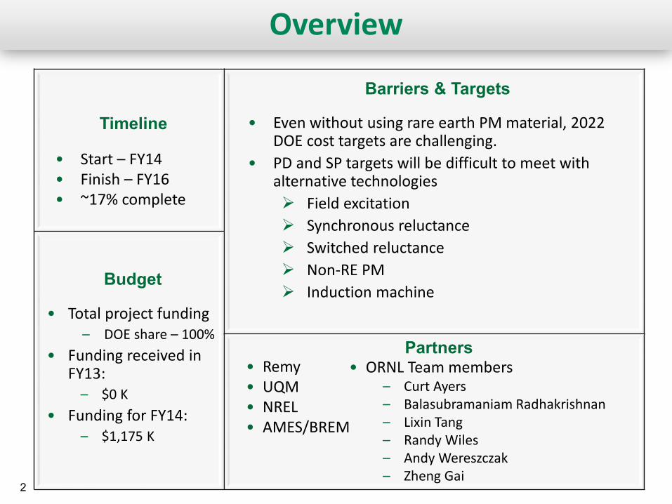
Overview
• Start – FY14 • Finish – FY16 • ~17% complete
• Even without using rare earth PM material, 2022 DOE cost targets are challenging.
• PD and SP targets will be difficult to meet with alternative technologies Field excitation Synchronous reluctance Switched reluctance Non-RE PM Induction machine
• Total project funding – DOE share – 100%
• Funding received in FY13:
– $0 K • Funding for FY14:
– $1,175 K
Timeline
Budget
Barriers & Targets
Partners • Remy • UQM • NREL • AMES/BREM
• ORNL Team members – Curt Ayers – Balasubramaniam Radhakrishnan – Lixin Tang – Randy Wiles – Andy Wereszczak – Zheng Gai
3 3
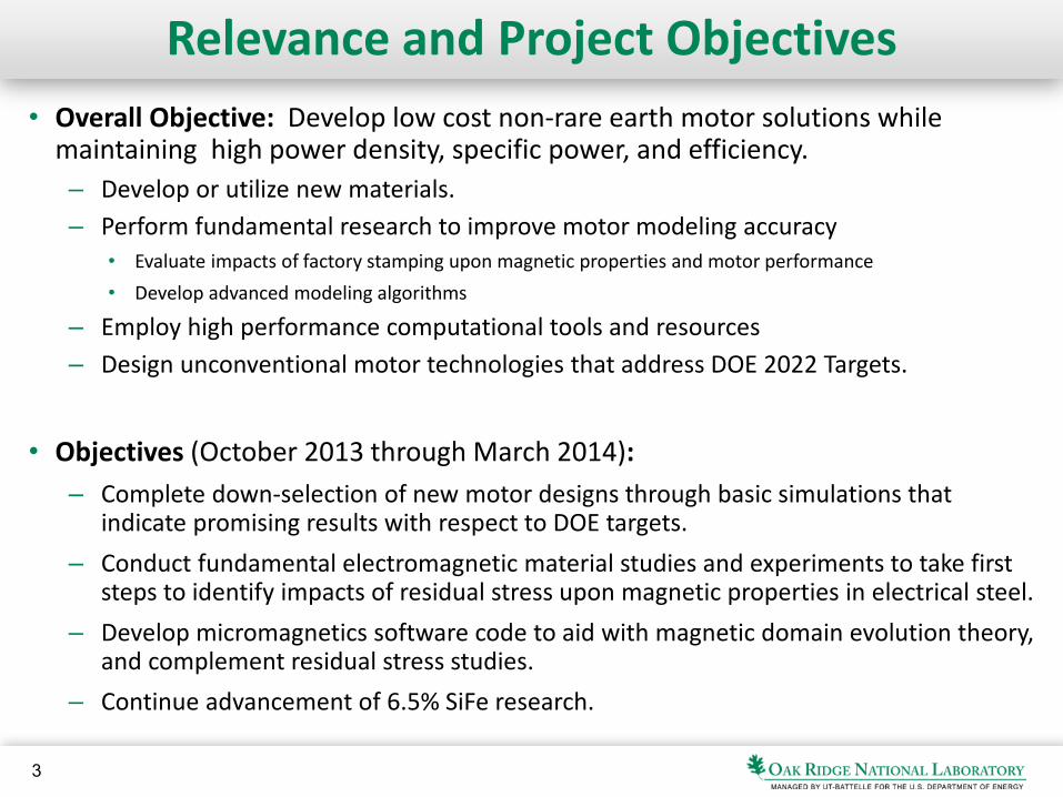
Relevance and Project Objectives • Overall Objective: Develop low cost non-rare earth motor solutions while
maintaining high power density, specific power, and efficiency. – Develop or utilize new materials. – Perform fundamental research to improve motor modeling accuracy
• Evaluate impacts of factory stamping upon magnetic properties and motor performance • Develop advanced modeling algorithms
– Employ high performance computational tools and resources – Design unconventional motor technologies that address DOE 2022 Targets.
• Objectives (October 2013 through March 2014): – Complete down-selection of new motor designs through basic simulations that
indicate promising results with respect to DOE targets. – Conduct fundamental electromagnetic material studies and experiments to take first
steps to identify impacts of residual stress upon magnetic properties in electrical steel. – Develop micromagnetics software code to aid with magnetic domain evolution theory,
and complement residual stress studies. – Continue advancement of 6.5% SiFe research.
4 4
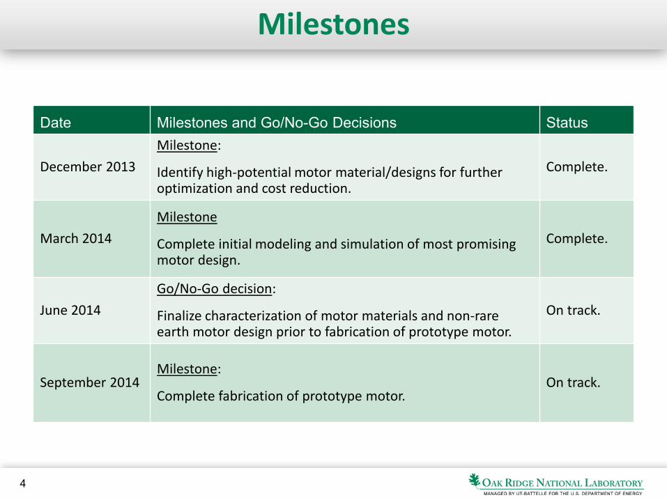
Milestones
Date Milestones and Go/No-Go Decisions Status
December 2013 Milestone:
Identify high-potential motor material/designs for further optimization and cost reduction.
Complete.
March 2014 Milestone
Complete initial modeling and simulation of most promising motor design.
Complete.
June 2014 Go/No-Go decision:
Finalize characterization of motor materials and non-rare earth motor design prior to fabrication of prototype motor.
On track.
September 2014 Milestone:
Complete fabrication of prototype motor. On track.
5
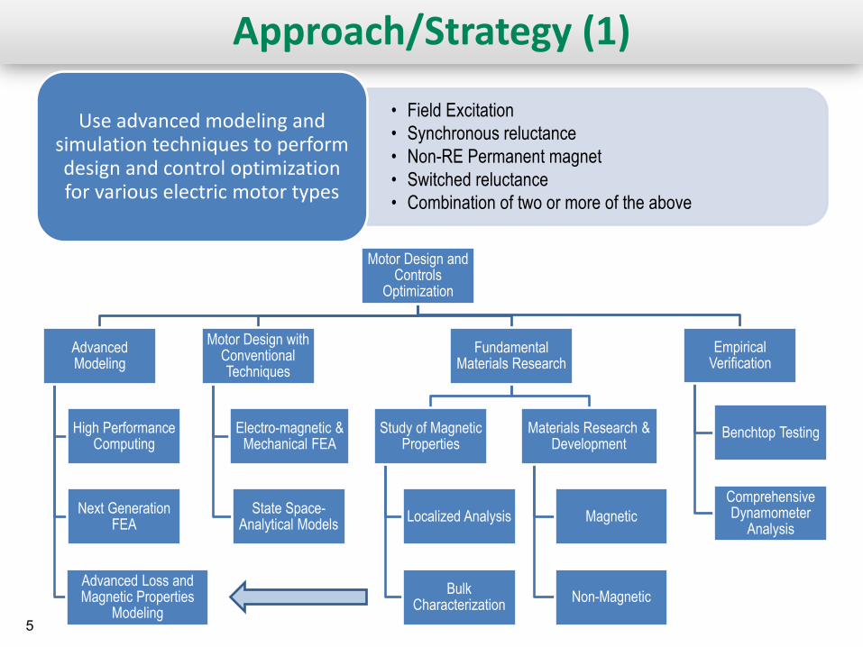
Approach/Strategy (1)
• Field Excitation • Synchronous reluctance • Non-RE Permanent magnet • Switched reluctance • Combination of two or more of the above
Use advanced modeling and simulation techniques to perform design and control optimization for various electric motor types
Motor Design and Controls
Optimization
Advanced Modeling
High Performance Computing
Next Generation FEA
Advanced Loss and Magnetic Properties
Modeling
Motor Design with Conventional Techniques
Electro-magnetic & Mechanical FEA
State Space-Analytical Models
Fundamental Materials Research
Study of Magnetic Properties
Localized Analysis
Bulk Characterization
Materials Research & Development
Magnetic
Non-Magnetic
Empirical Verification
Benchtop Testing
Comprehensive Dynamometer
Analysis
6
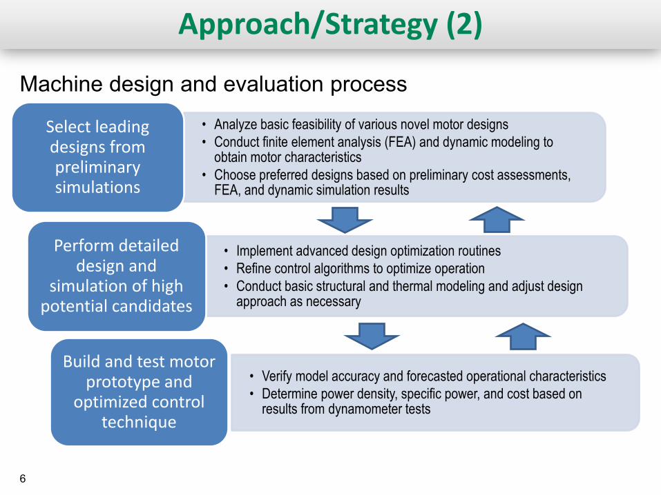
Approach/Strategy (2)
• Analyze basic feasibility of various novel motor designs • Conduct finite element analysis (FEA) and dynamic modeling to
obtain motor characteristics • Choose preferred designs based on preliminary cost assessments,
FEA, and dynamic simulation results
Select leading designs from preliminary simulations
• Implement advanced design optimization routines • Refine control algorithms to optimize operation • Conduct basic structural and thermal modeling and adjust design
approach as necessary
Perform detailed design and
simulation of high potential candidates
• Verify model accuracy and forecasted operational characteristics • Determine power density, specific power, and cost based on
results from dynamometer tests
Build and test motor prototype and
optimized control technique
Machine design and evaluation process
7
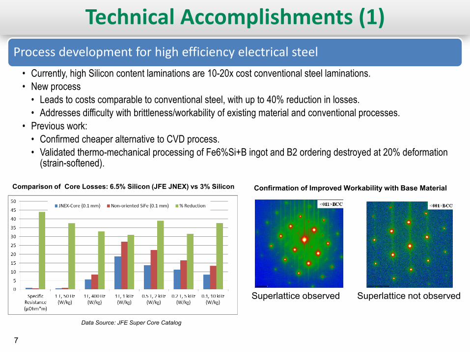
Technical Accomplishments (1) Process development for high efficiency electrical steel • Currently, high Silicon content laminations are 10-20x cost conventional steel laminations. • New process • Leads to costs comparable to conventional steel, with up to 40% reduction in losses. • Addresses difficulty with brittleness/workability of existing material and conventional processes.
• Previous work: • Confirmed cheaper alternative to CVD process. • Validated thermo-mechanical processing of Fe6%Si+B ingot and B2 ordering destroyed at 20% deformation
(strain-softened).
Data Source: JFE Super Core Catalog
Superlattice observed Superlattice not observed
Comparison of Core Losses: 6.5% Silicon (JFE JNEX) vs 3% Silicon Confirmation of Improved Workability with Base Material
8
Technical Accomplishments (2)
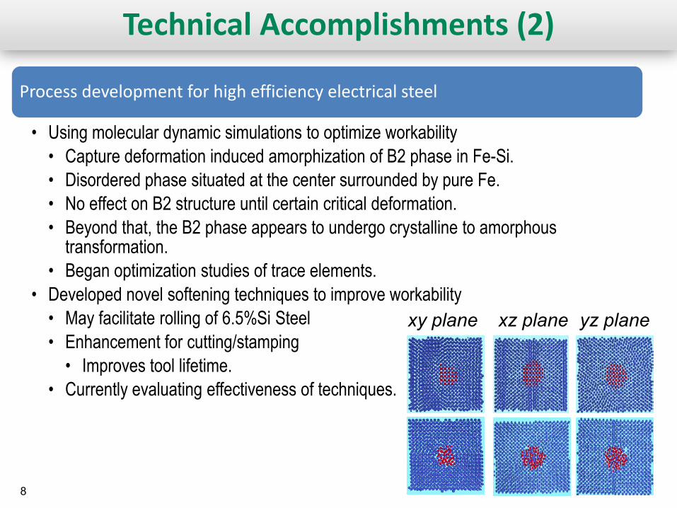
Process development for high efficiency electrical steel
• Using molecular dynamic simulations to optimize workability • Capture deformation induced amorphization of B2 phase in Fe-Si. • Disordered phase situated at the center surrounded by pure Fe. • No effect on B2 structure until certain critical deformation. • Beyond that, the B2 phase appears to undergo crystalline to amorphous
transformation. • Began optimization studies of trace elements.
• Developed novel softening techniques to improve workability • May facilitate rolling of 6.5%Si Steel • Enhancement for cutting/stamping • Improves tool lifetime.
• Currently evaluating effectiveness of techniques.
xy plane xz plane yz plane
9
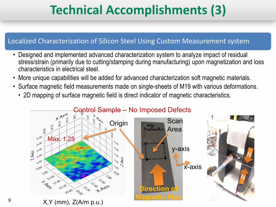
Technical Accomplishments (3)
Localized Characterization of Silicon Steel Using Custom Measurement system
• Designed and implemented advanced characterization system to analyze impact of residual stress/strain (primarily due to cutting/stamping during manufacturing) upon magnetization and loss characteristics in electrical steel.
• More unique capabilities will be added for advanced characterization soft magnetic materials. • Surface magnetic field measurements made on single-sheets of M19 with various deformations. • 2D mapping of surface magnetic field is direct indicator of magnetic characteristics.
Direction of Magnetic Flux
Scan Area
Control Sample – No Imposed Defects
X,Y (mm), Z(A/m p.u.)
Max: 1.25
Origin
x-axis
y-axis
10
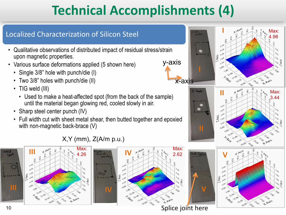
Technical Accomplishments (4) Localized Characterization of Silicon Steel
• Qualitative observations of distributed impact of residual stress/strain upon magnetic properties.
• Various surface deformations applied (5 shown here) • Single 3/8” hole with punch/die (I) • Two 3/8” holes with punch/die (II) • TIG weld (III) • Used to make a heat-affected spot (from the back of the sample)
until the material began glowing red, cooled slowly in air. • Sharp steel center punch (IV) • Full width cut with sheet metal shear, then butted together and epoxied
with non-magnetic back-brace (V)
Max: 4.98
I
I
II
III IV
II
III IV
Max: 3.44
Max: 4.26
Max: 2.62
X,Y (mm), Z(A/m p.u.)
Splice joint here
x-axis
y-axis
V
V
11
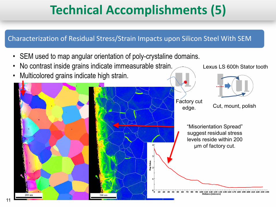
Technical Accomplishments (5)
Characterization of Residual Stress/Strain Impacts upon Silicon Steel With SEM
• SEM used to map angular orientation of poly-crystaline domains. • No contrast inside grains indicate immeasurable strain. • Multicolored grains indicate high strain.
Cut, mount, polish
“Misorientation Spread” suggest residual stress levels reside within 200
μm of factory cut.
Lexus LS 600h Stator tooth
Factory cut edge.
12
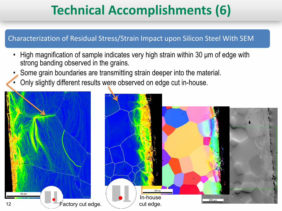
Technical Accomplishments (6)
Characterization of Residual Stress/Strain Impact upon Silicon Steel With SEM
• High magnification of sample indicates very high strain within 30 μm of edge with strong banding observed in the grains.
• Some grain boundaries are transmitting strain deeper into the material. • Only slightly different results were observed on edge cut in-house.
In-house cut edge. Factory cut edge.
13
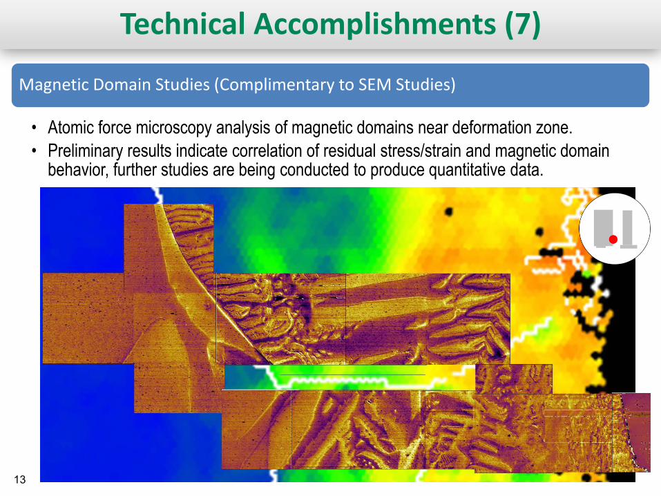
Technical Accomplishments (7)
Magnetic Domain Studies (Complimentary to SEM Studies)
• Atomic force microscopy analysis of magnetic domains near deformation zone. • Preliminary results indicate correlation of residual stress/strain and magnetic domain
behavior, further studies are being conducted to produce quantitative data.
14
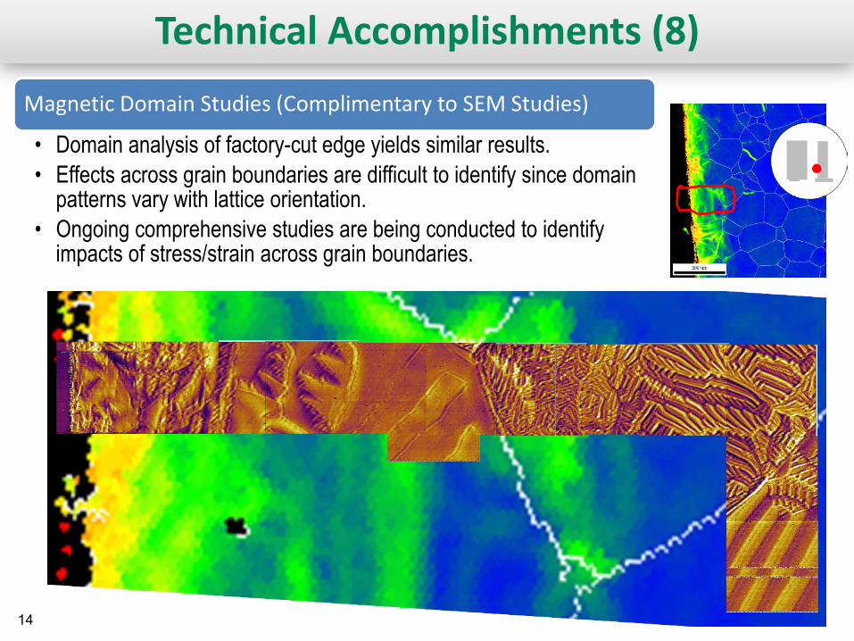
Magnetic Domain Studies (Complimentary to SEM Studies)
• Domain analysis of factory-cut edge yields similar results. • Effects across grain boundaries are difficult to identify since domain
patterns vary with lattice orientation. • Ongoing comprehensive studies are being conducted to identify
impacts of stress/strain across grain boundaries.
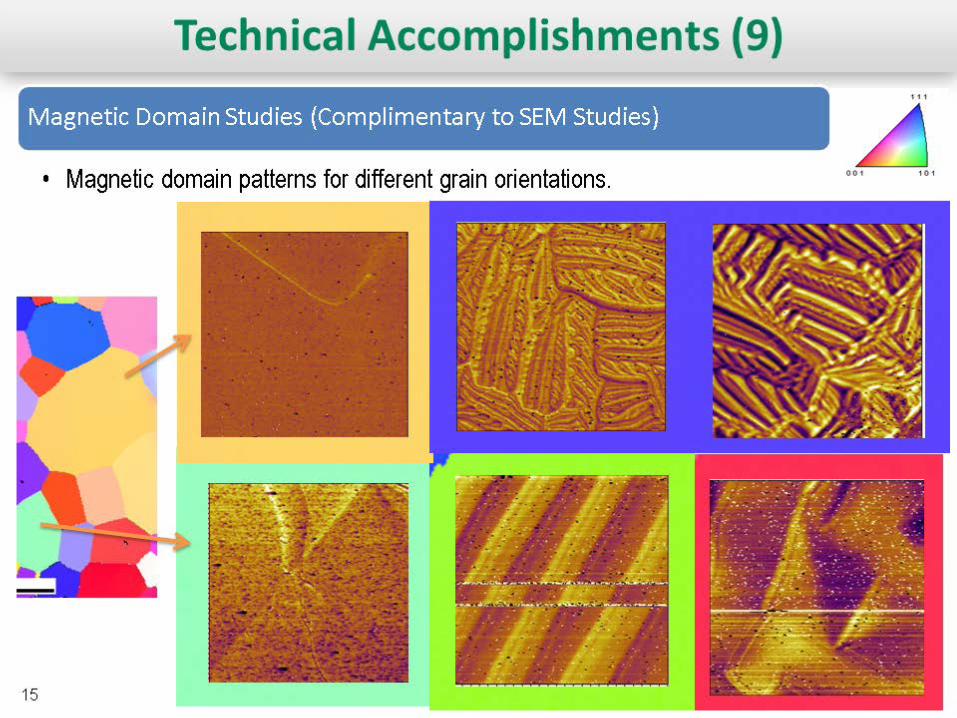
Technical Accomplishments (8)
15
16
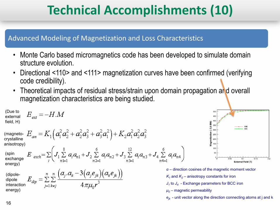
Technical Accomplishments (10)
Advanced Modeling of Magnetization and Loss Characteristics
• Monte Carlo based micromagnetics code has been developed to simulate domain structure evolution.
• Directional <110> and <111> magnetization curves have been confirmed (verifying code credibility).
• Theoretical impacts of residual stress/strain upon domain propagation and overall magnetization characteristics are being studied.
(Due to external field, H)
(magneto-crystalline anisotropy)
(spin exchange energy)
(dipole-dipole interaction energy)
α – direction cosines of the magnetic moment vector
K1 and K2 – anisotropy constants for iron
J1 to J4 - Exchange parameters for BCC iron
μ0 – magnetic permeability
ejk - unit vector along the direction connecting atoms at j and k
17
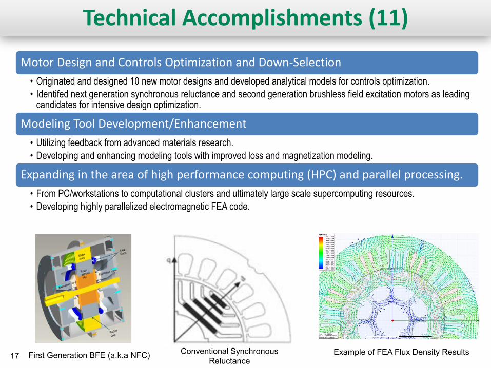
Technical Accomplishments (11)
First Generation BFE (a.k.a NFC) Conventional Synchronous Reluctance
Example of FEA Flux Density Results
Motor Design and Controls Optimization and Down-Selection • Originated and designed 10 new motor designs and developed analytical models for controls optimization. • Identifed next generation synchronous reluctance and second generation brushless field excitation motors as leading
candidates for intensive design optimization.
Modeling Tool Development/Enhancement • Utilizing feedback from advanced materials research. • Developing and enhancing modeling tools with improved loss and magnetization modeling.
Expanding in the area of high performance computing (HPC) and parallel processing. • From PC/workstations to computational clusters and ultimately large scale supercomputing resources. • Developing highly parallelized electromagnetic FEA code.
18
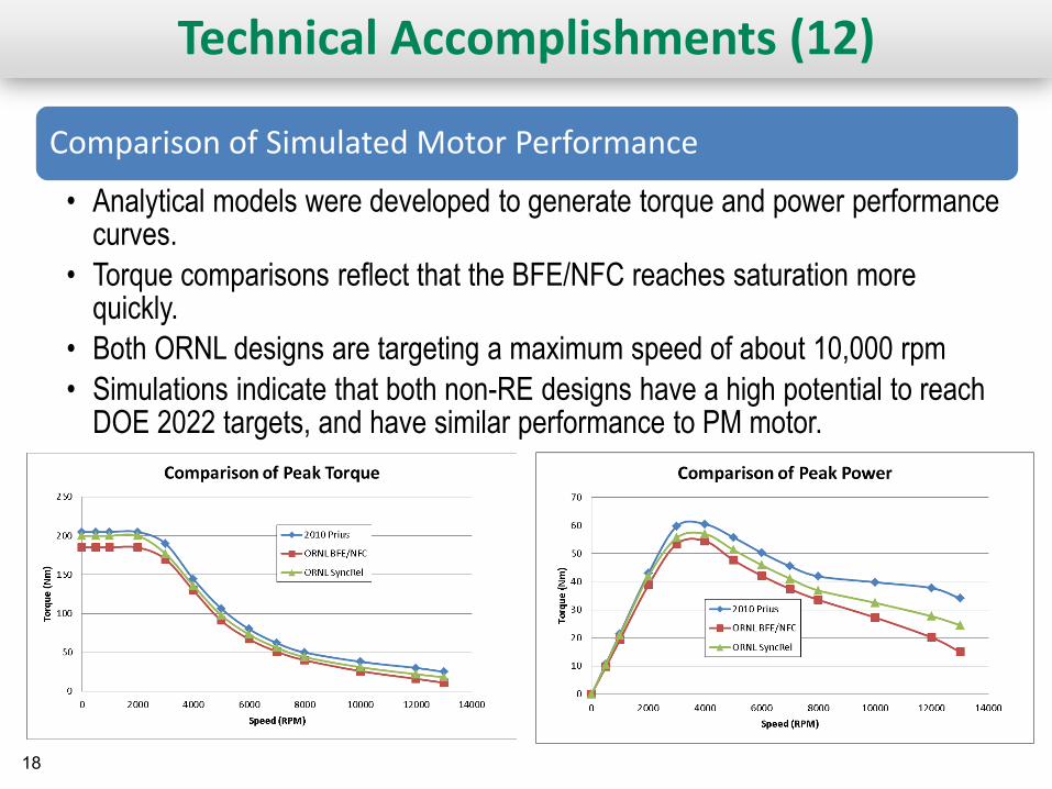
Technical Accomplishments (12)
Comparison of Simulated Motor Performance
• Analytical models were developed to generate torque and power performance curves.
• Torque comparisons reflect that the BFE/NFC reaches saturation more quickly.
• Both ORNL designs are targeting a maximum speed of about 10,000 rpm • Simulations indicate that both non-RE designs have a high potential to reach
DOE 2022 targets, and have similar performance to PM motor.
19
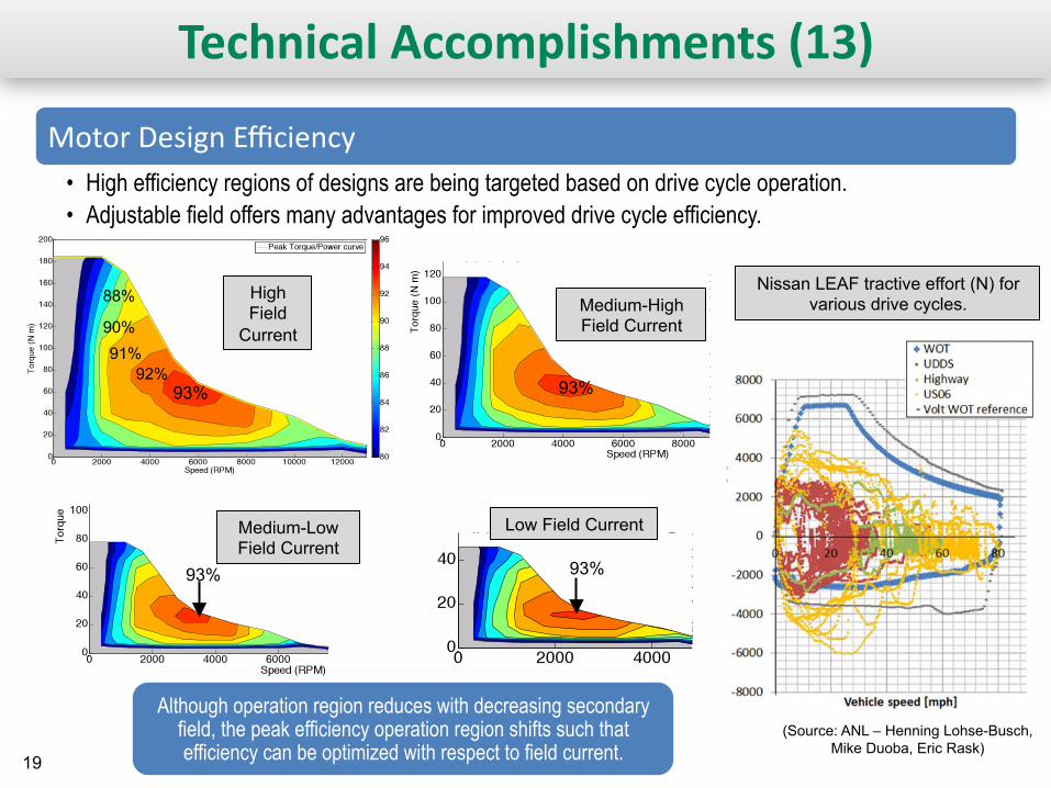
Technical Accomplishments (13)
Motor Design Efficiency • High efficiency regions of designs are being targeted based on drive cycle operation. • Adjustable field offers many advantages for improved drive cycle efficiency.
Although operation region reduces with decreasing secondary field, the peak efficiency operation region shifts such that efficiency can be optimized with respect to field current.
Nissan LEAF tractive effort (N) for various drive cycles.
93% 92%
91% 90%
88%
93%
93% 93%
High Field
Current
Low Field Current Medium-Low Field Current
Medium-High Field Current
(Source: ANL – Henning Lohse-Busch, Mike Duoba, Eric Rask)

20 20
Responses to Previous Year Reviewers’ Comments
• This project is a new start.
21 21
Collaborations and Coordination
Organization Type of Collaboration/Coordination
Remy • Collaborating on motor controls.
UQM • ORNL, NREL, and UQM are collaborating on the use of injection molded
potting compounds for improved reliability, heat transfer, and overall power density and specific power.
NREL • ORNL will provide heat generation map throughout motor for NREL to develop integrated cooling techniques.
Ames Lab • ORNL is attending BREM review meetings, workshops, and WebEx
updates to keep up to date on non-RE PM alternative development, and keeping design options available for use of new PM developments.
22
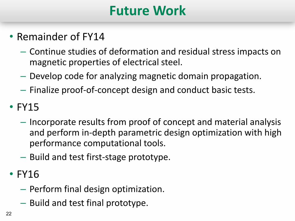
Future Work
• Remainder of FY14 – Continue studies of deformation and residual stress impacts on
magnetic properties of electrical steel. – Develop code for analyzing magnetic domain propagation. – Finalize proof-of-concept design and conduct basic tests.
• FY15 – Incorporate results from proof of concept and material analysis
and perform in-depth parametric design optimization with high performance computational tools.
– Build and test first-stage prototype.
• FY16 – Perform final design optimization. – Build and test final prototype.
23
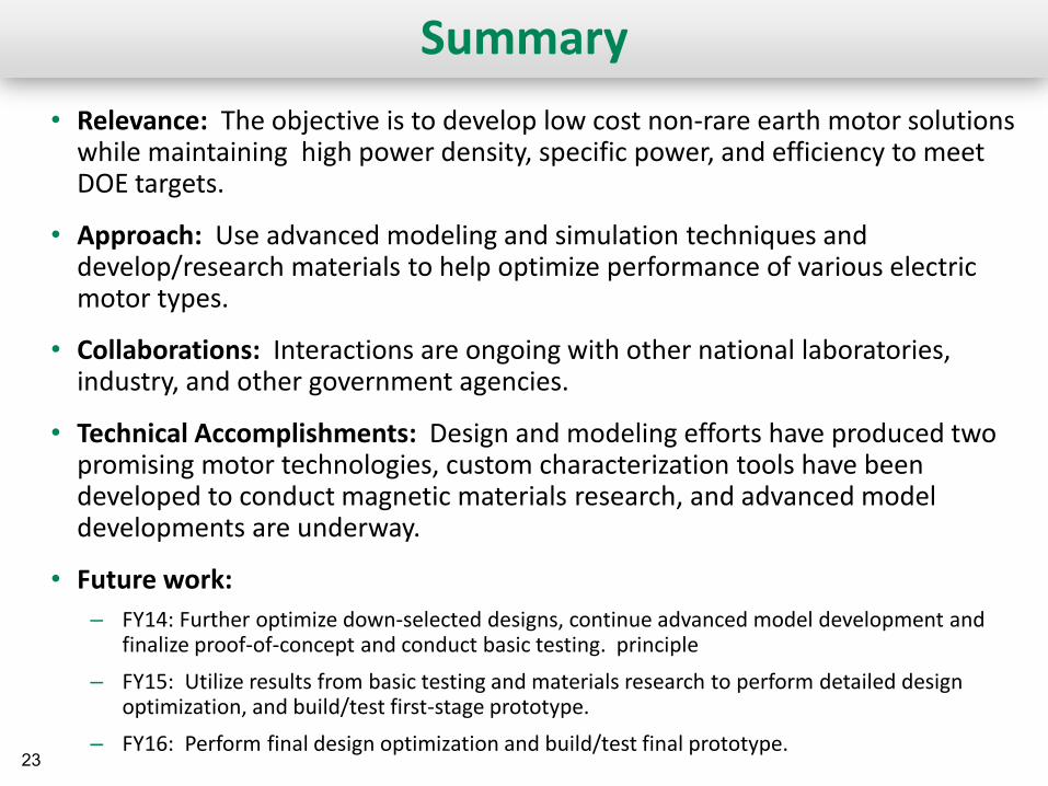
Summary • Relevance: The objective is to develop low cost non-rare earth motor solutions
while maintaining high power density, specific power, and efficiency to meet DOE targets.
• Approach: Use advanced modeling and simulation techniques and develop/research materials to help optimize performance of various electric motor types.
• Collaborations: Interactions are ongoing with other national laboratories, industry, and other government agencies.
• Technical Accomplishments: Design and modeling efforts have produced two promising motor technologies, custom characterization tools have been developed to conduct magnetic materials research, and advanced model developments are underway.
• Future work: – FY14: Further optimize down-selected designs, continue advanced model development and
finalize proof-of-concept and conduct basic testing. principle
– FY15: Utilize results from basic testing and materials research to perform detailed design optimization, and build/test first-stage prototype.
– FY16: Perform final design optimization and build/test final prototype.

![SCALABLE...SCALABLE Network Technologies n +1.424.603.6361 n info@scalable-networks.com n scalable-networks.com[1] These libraries are subject to export restriction under the International](https://img.pdfslide.us/doc/110x75/60935fad4a1de67d8313f100/scalable-scalable-network-technologies-n-14246036361-n-infoscalable-networkscom.jpg)