Embed Size (px)
Citation preview

Scalable Manufacturing of Energetic Materials
for Integrated Systems
Stephen Tse, Alberto Cuitino, Fernando Muzzio,
Assimina Pelegri, and Bernard Kear
School of Engineering, Rutgers University
Piscataway, NJ 08854
Inaugural Meeting of the National Energetic Materials Consortium
Texas Tech University
13 October 2015
Outline
Nanowire Synthesis of NanoEnergetics
Nanoparticle Synthesis of Cubic Boron Nitride
In-situ Laser-Based Diagnostics
Graphene Synthesis
Characterization and Continuous Automation of an Environmentally Green Primer

Nanowire Synthesis
Relevance -- Nanowires
Robust materials with improved properties are needed for structural, functional, and device applications
Of strong interest are functional one-dimensional nanostructures due to their unique and innovative applications in optics, optoelectronics, catalysis, and piezoelectricity
Semiconducting oxide nanowires constitute a unique group of 1D nanomaterials, which have well-defined and uniform shapes, stable surfaces, and single-crystal volumes
These properties are keys to nanoelectronic applications like use as field effect transistors, ultra-sensitive nano-size gas sensors, nanoresonators, and nanocantilevers

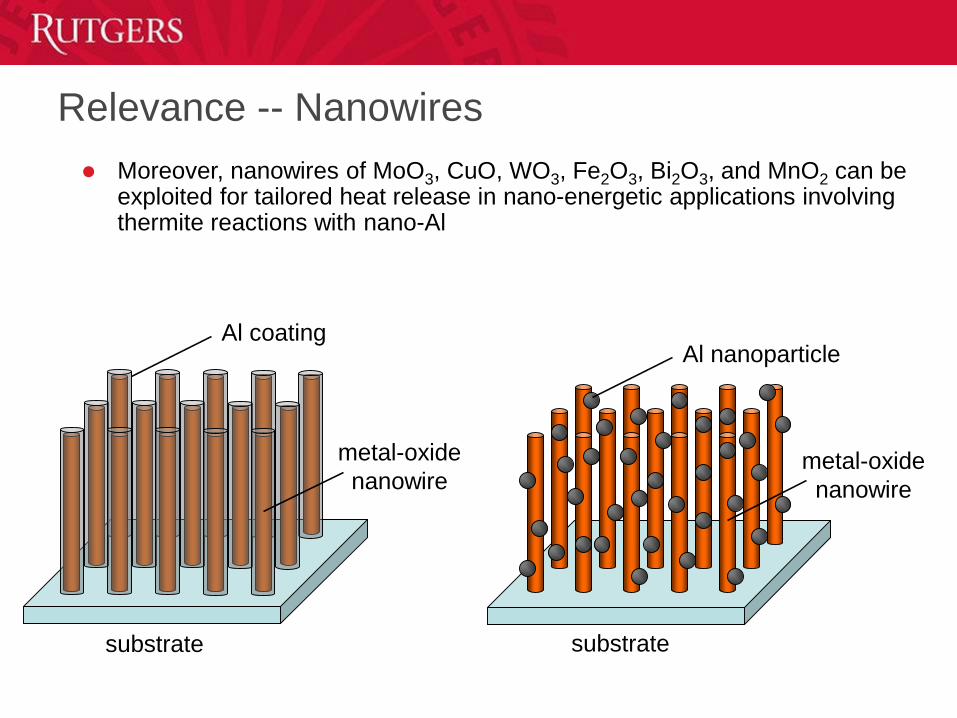
Relevance -- Nanowires
Moreover, nanowires of MoO3, CuO, WO3, Fe2O3, Bi2O3, and MnO2 can be exploited for tailored heat release in nano-energetic applications involving thermite reactions with nano-Al
substrate
metal-oxide
nanowire
Al coatingAl nanoparticle
metal-oxide
nanowire
substrate
Motivation
Many approaches have been used to prepare nano-wires/rods, such as vapor-liquid-solid growth, solution-liquid-solid methods, template mediate growth, electron beam lithography, and scanning tunneling microscopy techniques
However, these methods can be complex, involving pretreatment, catalysts, and vacuum systems, while still characterized by low single-nanowire growth rates and low total yield densities
Consequently, studies on nanoscale materials and their applications are presently limited due to lack of easy processes for high- rate, yield, purity, and orientation synthesis of such materials
The growth of metal-oxide nanowires over large areas remains especially challenging
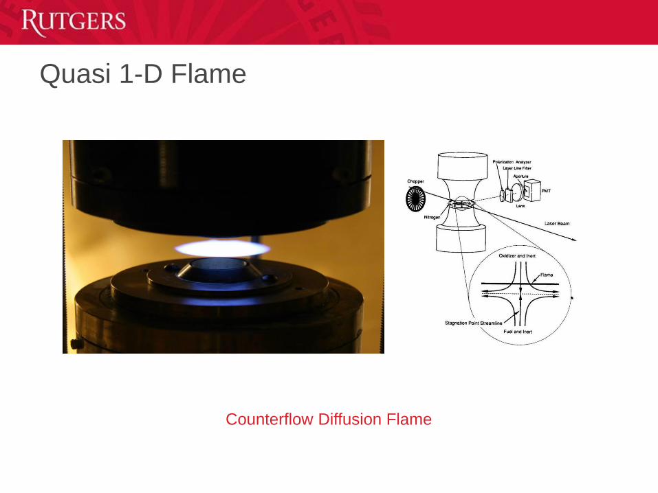
Quasi 1-D Flame
Counterflow Diffusion Flame
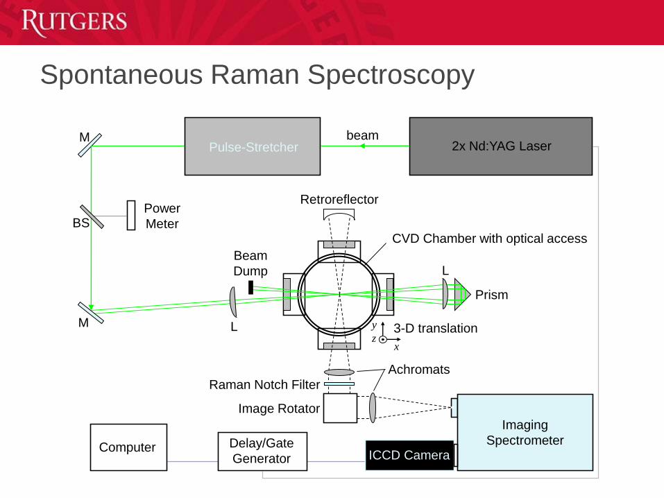
Spontaneous Raman Spectroscopy
2x Nd:YAG LaserPulse-StretcherM
M
BSPower
Meter
Image Rotator
ICCD Camera
Prism
Imaging
Spectrometer
L
L
Raman Notch Filter
Achromats
Beam
Dump
Retroreflector
x
y
z3-D translation
CVD Chamber with optical access
Delay/Gate
GeneratorComputer
beam
Axi-symmetric counterflow diffusion flame
code
GRI-Mech 1.2 (32 species, 177 reactions)
Transport properties computed with
CHEMKIN subroutines
Boundary conditions at burners specify plug
flow inlet mass flux and temperature
Gas-Phase Simulation
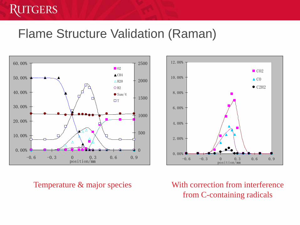
Temperature & major species With correction from interference
from C-containing radicals
0.00%
10.00%
20.00%
30.00%
40.00%
50.00%
60.00%
-0.6 -0.3 0 0.3 0.6 0.9position/mm
0
500
1000
1500
2000
2500O2
CH4
H20
H2
Sum/4
T
0.00%
2.00%
4.00%
6.00%
8.00%
10.00%
12.00%
-0.6 -0.3 0 0.3 0.6 0.9position/mm
CO2
CO
C2H2
Flame Structure Validation (Raman)
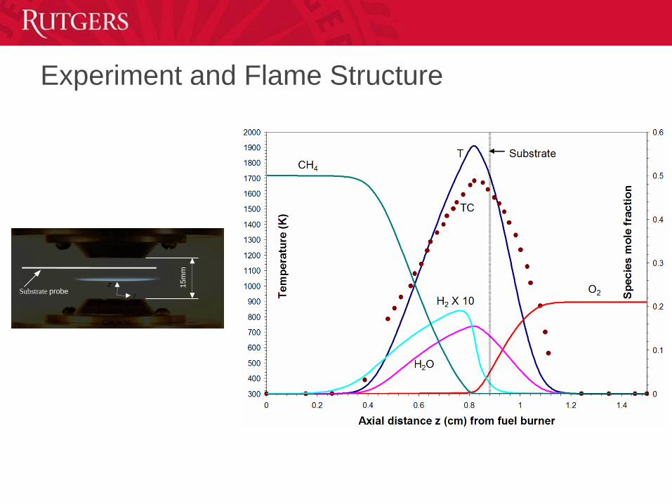
15m
m
Air nozzle
CH4 + N2
Fuel nozzle
Substrate prober
z
Experiment and Flame Structure

Dense yield of nanomaterials grown directly on a tungsten substrate
Diameters of 20-50nm, lengths > 10µm, 10min sampling duration
EDX tungsten oxide
Aligned Tungsten-Oxide Nanowires
20 nm
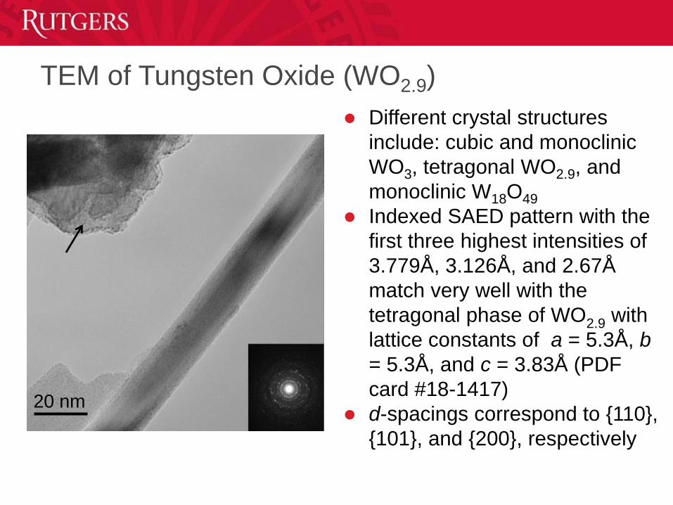
Different crystal structures
include: cubic and monoclinic
WO3, tetragonal WO2.9, and
monoclinic W18O49
Indexed SAED pattern with the
first three highest intensities of
3.779Å, 3.126Å, and 2.67Å
match very well with the
tetragonal phase of WO2.9 with
lattice constants of a = 5.3Å, b
= 5.3Å, and c = 3.83Å (PDF
card #18-1417)
d-spacings correspond to {110},
{101}, and {200}, respectively
TEM of Tungsten Oxide (WO2.9)

10 nm
0.378 nm
[110]
Dislocation-free, single-crystalline
2-D Fourier transform pattern gives
average spacing for lattice planes of
3.78Å, which corresponds to the
reflections from d-spacings of (110)
planes of the tetragonal WO2.9 phase
Preferable growth along the [110]
direction
Crystallinity
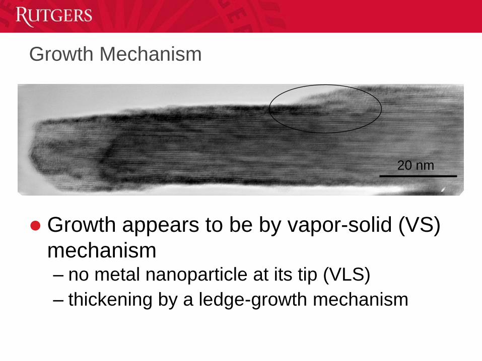
Growth appears to be by vapor-solid (VS)
mechanism– no metal nanoparticle at its tip (VLS)
– thickening by a ledge-growth mechanism
20 nm
Growth Mechanism
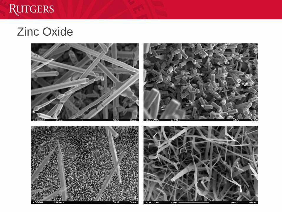
Zinc Oxide
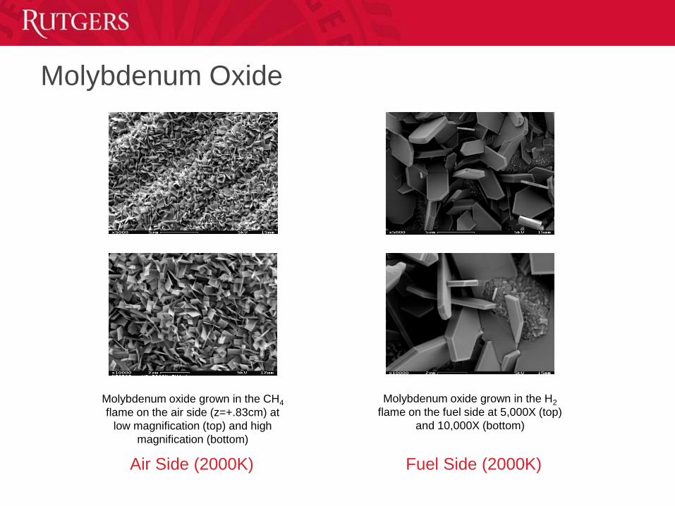
Molybdenum Oxide
Molybdenum oxide grown in the CH4
flame on the air side (z=+.83cm) at
low magnification (top) and high
magnification (bottom)
Molybdenum oxide grown in the H2
flame on the fuel side at 5,000X (top)
and 10,000X (bottom)
Fuel Side (2000K)Air Side (2000K)

Copper Oxide
Low magnification copper oxide
nanowires grown in a CH4 flame
(z=+0.97cm) (top)
Magnified FESEM image of
nanowires grown in CH4 (bottom)
Low magnification showing yield of
copper oxide from H2 flame
(z=+0.97cm) (top)
Typical image of copper oxide grown
in the H2 flame (bottom)
Air Side (900K)
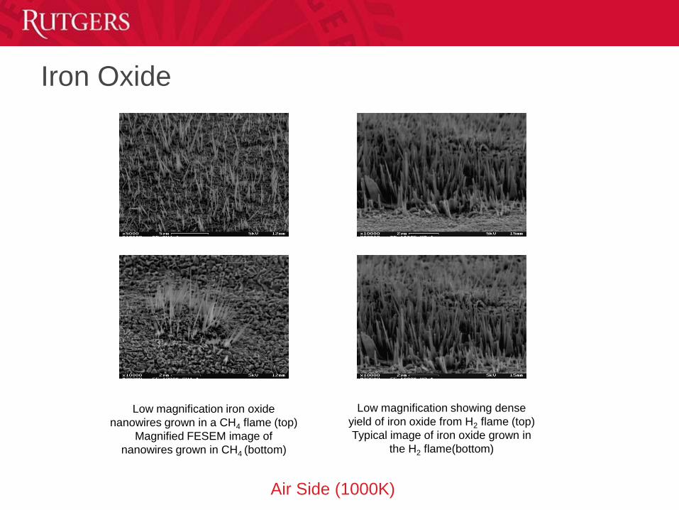
Iron Oxide
Low magnification iron oxide
nanowires grown in a CH4 flame (top)
Magnified FESEM image of
nanowires grown in CH4 (bottom)
Low magnification showing dense
yield of iron oxide from H2 flame (top)
Typical image of iron oxide grown in
the H2 flame(bottom)
Air Side (1000K)
Energetics
Nanoscale energetic materials have the potential for
enhanced energy release and mechanical properties, versus
their conventional counterparts
Energetic nanomixtures and nanocomposites e.g. Thermite
reactions (Al/MoO3, Al/CuO, Al/WO3, Al/Fe2O3, Al/Bi2O3, and
Al/MnO2)
– Based on intermolecular, rather than intramolecular, reactions,
energetic nanocomposites require intimate mixing of the
reactants on the nanometer length scale
– The use of nanoscale structures enhance chemical kinetics due
to their high surface area and short diffusion length
– Given the proximity and uniformity of the fuel and oxidizer
nanostructures, the final nanophase composite can be extremely
dense in energy and capable of generating high power
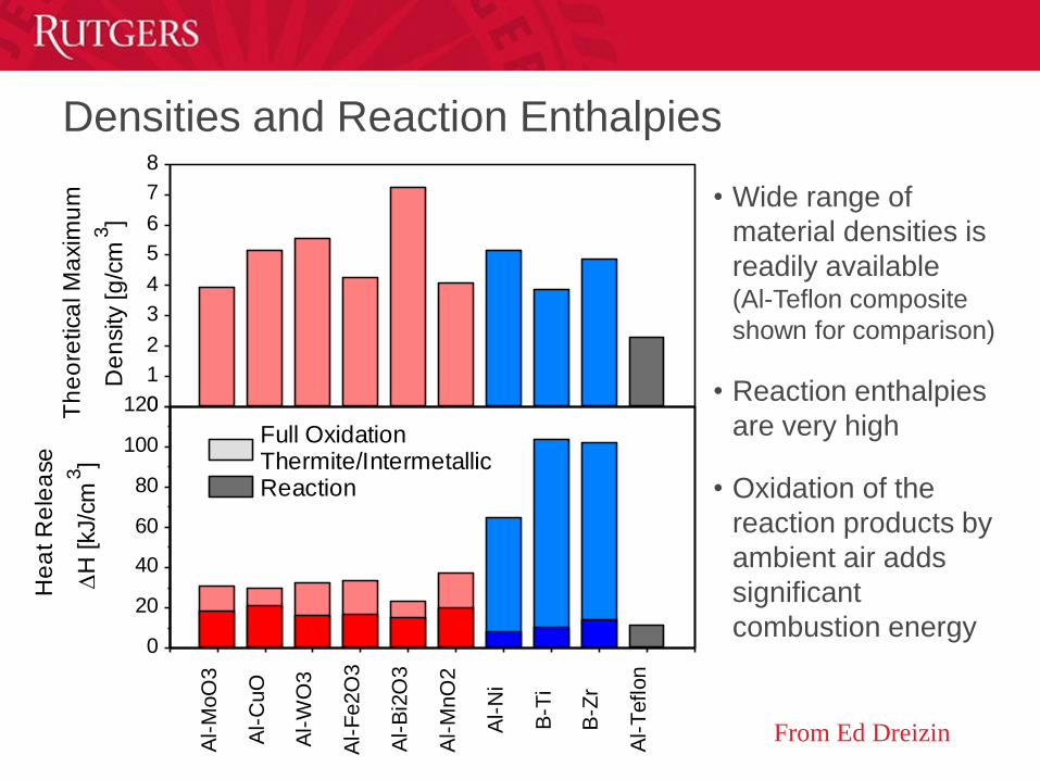
Densities and Reaction Enthalpies
From Ed Dreizin
0
20
40
60
80
100
120
He
at R
ele
ase
H
[kJ/c
m3]
Al-
MoO
3
Al-
CuO
Al-
WO
3
Al-
Fe2O
3
Al-
Bi2
O3
Al-
MnO
2
Al-
Ni
B-T
i
B-Z
r
Al-
Teflon
Full OxidationThermite/Intermetallic Reaction
0
1
2
3
4
5
6
7
8
Th
eo
retica
l M
axim
um
D
en
sity [g
/cm
3]
• Wide range of
material densities is
readily available (Al-Teflon composite
shown for comparison)
• Reaction enthalpies
are very high
• Oxidation of the
reaction products by
ambient air adds
significant
combustion energy
Relevance -- Nanowires
Moreover, nanowires of MoO3, CuO, WO3, Fe2O3, Bi2O3, and MnO2 can be exploited for tailored heat release in nano-energetic applications involving thermite reactions with nano-Al
substrate
metal-oxide
nanowire
Al coatingAl nanoparticle
metal-oxide
nanowire
substrate
Nanoenergetic Materials for MEMS
Zhang et al., Applied Physics Letters, 2007
– Grew CuOx nanowires by thermal oxidation of electroplated Cu
layer
Nanoenergetic Materials for MEMS
Menon et al., Applied Physics Letters, 2004
– embedded an array of Fe2O3 nanowires inside a thin Al film
(1) Electrochemical anodization of Al foil to form nanoporous
alumina templates
(2) Fe nanowire fabricated inside nanopores by electrochemical
deposition
(3) Etching of alumina walls to reveal Fe nanowires
(4) Fe nanowires oxidized into Fe2O3 nanowires by annealing
Experiment Set-up
W
Burner
Burner
Al coatingWO2.9 NW
Step 2
Bath
Al
Step 1 Step 2
Electrodeposition Procedure
• Tungsten oxide nanowires array fabricated by flame synthesis
method.
• Al layer with thickness of ~16nm directly deposited on the
surface of WO2.9 nanowires by the ionic-liquid
electrodeposition method under an inert atmosphere.
• A 1.5:1 molar ratio of aluminum chloride and 1-ethyl-3-
methylimidazolium chloride ionic liquids were employed as the
electrolyte at room temperature.
• The working electrodes were a tungsten wire with WO2.9
nanowires grown on its surface and an aluminum wire. A
potential of -1.5 V DC was applied for 15 minutes to fabricate
the desired coaxial WO2.9/Al nanowires.
Jiang, T.; Chollier Brym, M. J.; Dubé, G.; Lasia, A.; Brisard, G. M.
Surf. Coatings Technol. 2006, 201, 1–9.
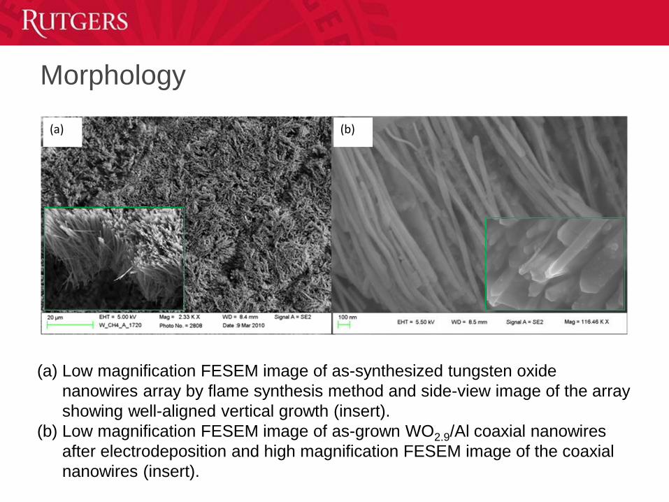
Morphology
(a) (b)
(a) Low magnification FESEM image of as-synthesized tungsten oxide
nanowires array by flame synthesis method and side-view image of the array
showing well-aligned vertical growth (insert).
(b) Low magnification FESEM image of as-grown WO2.9/Al coaxial nanowires
after electrodeposition and high magnification FESEM image of the coaxial
nanowires (insert).
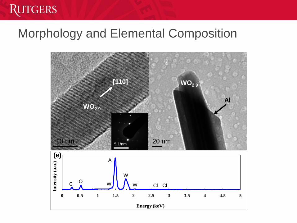
Morphology and Elemental Composition
0 0.5 1 1.5 2 2.5 3 3.5 4 4.5 5
Inte
nsi
ty (
a.u
.)
Energy (keV)
CO
Al
W
W
W Cl Cl
10 nm5 1/nm
[110]
WO2.9
20 nm
WO2.9
Al
(e)
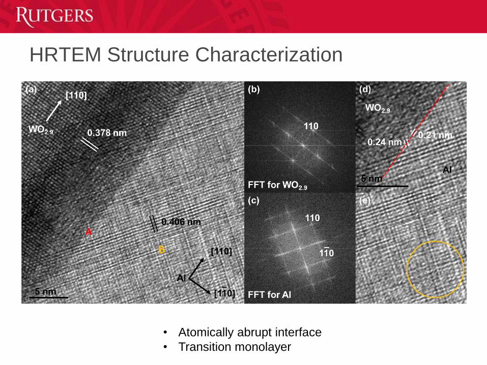
HRTEM Structure Characterization
• Atomically abrupt interface
• Transition monolayer
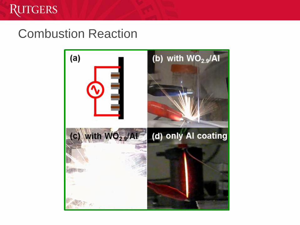
Combustion Reaction
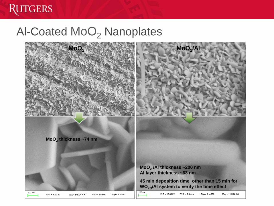
Al-Coated MoO2 Nanoplates
MoO2 thickness ~74 nm
MoO2 /Al thickness ~200 nm
Al layer thickness ~63 nm
45 min deposition time other than 15 min for
WO2.9/Al system to verify the time effect
MoO2 MoO2/Al
Nanoparticle Synthesis of Cubic Boron Nitride
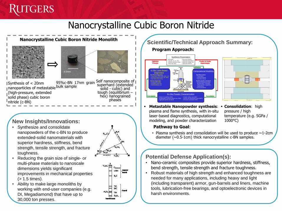
Potential Defense Application(s):• Nano-ceramic composites provide superior hardness, stiffness,
bend strength, tensile strength and fracture toughness. • Robust materials of high strength and enhanced toughness are
needed for many applications, including heavy and light
(including transparent) armor, gun-barrels and liners, machine
tools, lubrication-free bearings, and optoelectronic devices in
harsh environments.
Nanocrystalline Cubic Boron Nitride
Scientific/Technical Approach Summary:
Program Approach:
Pathway to Goal:
• Plasma synthesis and consolidation will be used to produce ~1-2cm diameter (~0.5-1cm) thick nanocrystalline c-BN samples.
New Insights/Innovations:• Synthesize and consolidate
nanopowders of the c-BN to produce
extended-solid nanomaterials with
superior hardness, stiffness, bend
strength, tensile strength, and fracture
toughness.
• Reducing the grain size of single- or
multi-phase materials to nanoscale
dimensions yields significant
improvements in mechanical properties
(> 1.5 times).
• Ability to make large monoliths by
working with end-user companies (e.g.
DI, Megadiamond) that have up to
30,000 ton presses.
Precursor
Plasma
gas
Auxiliary
gas
RF Coil
Evaporation
Dissociation
Reaction
Condensation
Nucleation
Quenching
Cold Substrate
Synthesis Parameters• RF power
• Gas (Ar, H2, N2, CH4)
• Ambient pressure & gas
• Mass flow rates
• Precursor loading
• Substrate temperature
• Substrate voltage bias
• Substrate distance
In-Situ Laser-Based
DiagnosticsGas-Phase diagnostics
• Temperature (SRS, FRS, OES. LIF)
• Chemical species (SRS, LIF, OES)
• Flow field velocity (PIV)
Particle diagnostics
• Composition (LIBS)
• Crystallinity (Raman)
• Size/Distribution (LII)
Ex-Situ Powder Characterization
• Phase & crystallinity (XRD)
• Morphologies & primary particle size (TEM)
• Aggregate particle size (DLS)
Computational Modeling
Gas-Phase phase
• Temperature
• Chemical species
• Flow field velocity
Particle growth & transport
• Sectional Model (precursor
decomposition, nucleation,
surface growth, coagulation,
coalescence)
• Aerosol dynamics
• Powder surface area (BET)
• Particle size distribution (nano-SMPS)
• Precursor conversion (TGA)
Correlation Correlation
Optimize
ProcessPredict & Guide
Experiments
ValidationPrecursor
Plasma
gas
Auxiliary
gas
RF Coil
Evaporation
Dissociation
Reaction
Condensation
Nucleation
Quenching
Cold Substrate
Synthesis Parameters• RF power
• Gas (Ar, H2, N2, CH4)
• Ambient pressure & gas
• Mass flow rates
• Precursor loading
• Substrate temperature
• Substrate voltage bias
• Substrate distance
In-Situ Laser-Based
DiagnosticsGas-Phase diagnostics
• Temperature (SRS, FRS, OES. LIF)
• Chemical species (SRS, LIF, OES)
• Flow field velocity (PIV)
Particle diagnostics
• Composition (LIBS)
• Crystallinity (Raman)
• Size/Distribution (LII)
Ex-Situ Powder Characterization
• Phase & crystallinity (XRD)
• Morphologies & primary particle size (TEM)
• Aggregate particle size (DLS)
Computational Modeling
Gas-Phase phase
• Temperature
• Chemical species
• Flow field velocity
Particle growth & transport
• Sectional Model (precursor
decomposition, nucleation,
surface growth, coagulation,
coalescence)
• Aerosol dynamics
• Powder surface area (BET)
• Particle size distribution (nano-SMPS)
• Precursor conversion (TGA)
Correlation Correlation
Optimize
ProcessPredict & Guide
Experiments
Validation
Metastable Nanopowder synthesis: plasma and flame synthesis, with in-situ laser-based diagnostics, computational modeling, and powder characterization
Consolidation: high pressure / high temperature (e.g. 5GPa / 1000°C)
4.5mm
Synthesis of < 20nm nanoparticles of metastable (high-pressure, extended solid phase) cubic boron nitride (c-BN)
95%c-BN 17nm grainbulk sample
B
C N
BN
B4+C
“C3N4”
B2CN2
BC2NBC4NBC3N
B4N
mol-%
B
mol-%
B
mol-% C
“C3N4”Cdiamond
c-BN
B4C
TiCSiC
Al2O3 TiN
Si3N4
super
hard
hard
hardness
B
C N
BN
B4+C
“C3N4”
B2CN2
BC2NBC4NBC3N
B4N
mol-%
B
mol-%
B
mol-% C
B
C N
BN
B4+C
“C3N4”
B2CN2
BC2NBC4NBC3N
B4N
mol-%
B
mol-%
B
mol-% C
“C3N4”Cdiamond
c-BN
B4C
TiCSiC
Al2O3 TiN
Si3N4
super
hard
hard
hardness
“C3N4”Cdiamond
c-BN
B4C
TiCSiC
Al2O3 TiN
Si3N4
super
hard
hard
hardness
Self nanocomposite of superhard (extended
solid - cubic) and tough (equilibrium –hex) nanograined
phases
B
C N
BN
B4+C
“C3N4”
B2CN2
BC2NBC4NBC3N
B4N
mol-%
B
mol-%
B
mol-% C
“C3N4”Cdiamond
c-BN
B4C
TiCSiC
Al2O3 TiN
Si3N4
super
hard
hard
hardness
B
C N
BN
B4+C
“C3N4”
B2CN2
BC2NBC4NBC3N
B4N
mol-%
B
mol-%
B
mol-% C
B
C N
BN
B4+C
“C3N4”
B2CN2
BC2NBC4NBC3N
B4N
mol-%
B
mol-%
B
mol-% C
“C3N4”Cdiamond
c-BN
B4C
TiCSiC
Al2O3 TiN
Si3N4
super
hard
hard
hardness
“C3N4”Cdiamond
c-BN
B4C
TiCSiC
Al2O3 TiN
Si3N4
super
hard
hard
hardness
Nanocrystalline Cubic Boron Nitride Monolith
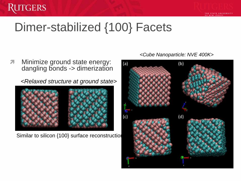
Dimer-stabilized {100} Facets
<Cube Nanoparticle: NVE 400K>
Minimize ground state energy: dangling bonds -> dimerization
<Relaxed structure at ground state>
Similar to silicon {100} surface reconstruction
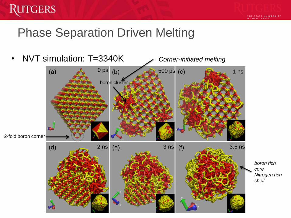
Phase Separation Driven Melting
0 ps 500 ps 1 ns
2 ns 3 ns 3.5 ns
2-fold boron corner
boron rich
core
Nitrogen rich
shell
• NVT simulation: T=3340K Corner-initiated melting
boron cluster
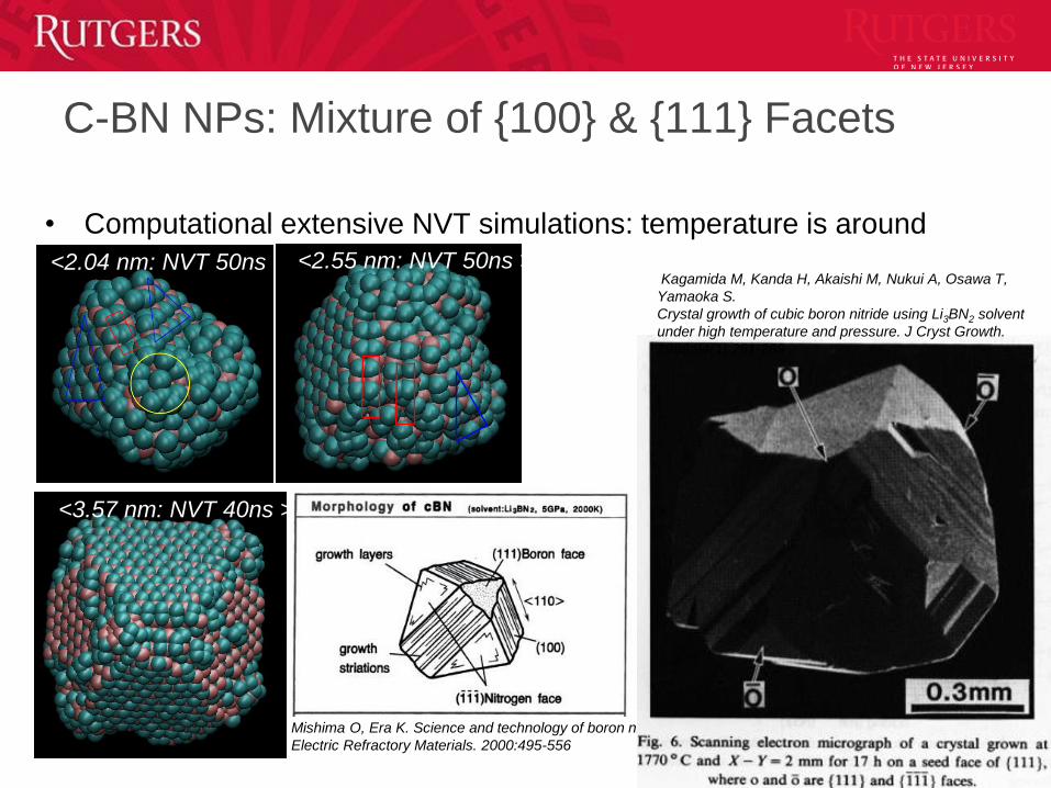
C-BN NPs: Mixture of {100} & {111} Facets
• Computational extensive NVT simulations: temperature is around
2900K
41
<2.04 nm: NVT 50ns >
<2.55 nm: NVT 50ns >
<3.57 nm: NVT 40ns >
Mishima O, Era K. Science and technology of boron nitride.
Electric Refractory Materials. 2000:495-556
<2.55 nm: NVT 50ns >Kagamida M, Kanda H, Akaishi M, Nukui A, Osawa T,
Yamaoka S.
Crystal growth of cubic boron nitride using Li3BN2 solvent
under high temperature and pressure. J Cryst Growth.
1989;94(1):261-269 .

Orientation Alignment and Grain Growth
100ps, T=2900K 38ns, T=3050K
0ps
• 50-ns NVE simulation with initial T=2815K
(100K~200K below melting temperature)
• Two octahedron nanoparticles align
gradually at temperature exceeds 2900K
• At 38ns, the temperature reaches 3050K
(above melting temperature)
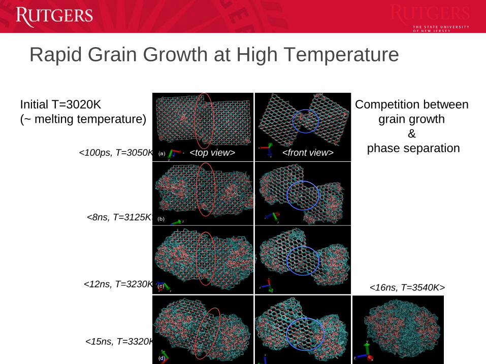
Rapid Grain Growth at High Temperature
<100ps, T=3050K>
<8ns, T=3125K>
<12ns, T=3230K>
<15ns, T=3320K>
<16ns, T=3540K>
Initial T=3020K
(~ melting temperature)
<top view> <front view>
Competition between
grain growth
&
phase separation

In-situ Laser-Based Diagnostics
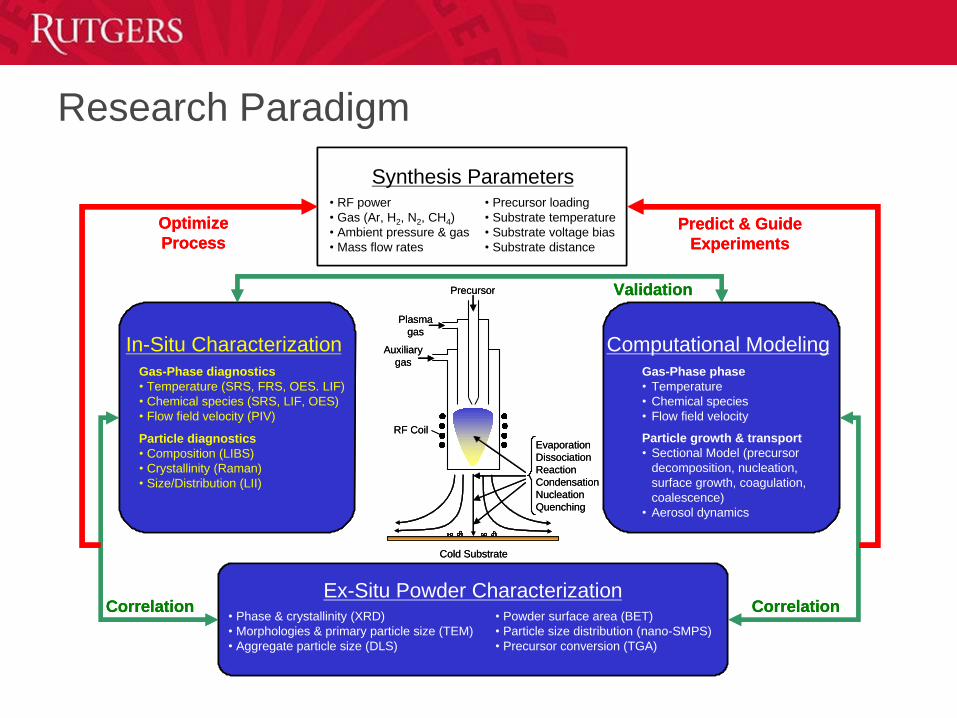
Research Paradigm
Precursor
Plasma
gas
Auxiliary
gas
RF Coil
Evaporation
Dissociation
Reaction
Condensation
Nucleation
Quenching
Cold Substrate
Synthesis Parameters• RF power
• Gas (Ar, H2, N2, CH4)
• Ambient pressure & gas
• Mass flow rates
• Precursor loading
• Substrate temperature
• Substrate voltage bias
• Substrate distance
In-Situ Characterization
Gas-Phase diagnostics
• Temperature (SRS, FRS, OES. LIF)
• Chemical species (SRS, LIF, OES)
• Flow field velocity (PIV)
Particle diagnostics
• Composition (LIBS)
• Crystallinity (Raman)
• Size/Distribution (LII)
Ex-Situ Powder Characterization• Phase & crystallinity (XRD)
• Morphologies & primary particle size (TEM)
• Aggregate particle size (DLS)
Computational Modeling
Gas-Phase phase
• Temperature
• Chemical species
• Flow field velocity
Particle growth & transport
• Sectional Model (precursor
decomposition, nucleation,
surface growth, coagulation,
coalescence)
• Aerosol dynamics
• Powder surface area (BET)
• Particle size distribution (nano-SMPS)
• Precursor conversion (TGA)
Correlation Correlation
Optimize
ProcessPredict & Guide
Experiments
ValidationPrecursor
Plasma
gas
Auxiliary
gas
RF Coil
Evaporation
Dissociation
Reaction
Condensation
Nucleation
Quenching
Cold Substrate
Synthesis Parameters• RF power
• Gas (Ar, H2, N2, CH4)
• Ambient pressure & gas
• Mass flow rates
• Precursor loading
• Substrate temperature
• Substrate voltage bias
• Substrate distance
In-Situ Characterization
Gas-Phase diagnostics
• Temperature (SRS, FRS, OES. LIF)
• Chemical species (SRS, LIF, OES)
• Flow field velocity (PIV)
Particle diagnostics
• Composition (LIBS)
• Crystallinity (Raman)
• Size/Distribution (LII)
Ex-Situ Powder Characterization• Phase & crystallinity (XRD)
• Morphologies & primary particle size (TEM)
• Aggregate particle size (DLS)
Computational Modeling
Gas-Phase phase
• Temperature
• Chemical species
• Flow field velocity
Particle growth & transport
• Sectional Model (precursor
decomposition, nucleation,
surface growth, coagulation,
coalescence)
• Aerosol dynamics
• Powder surface area (BET)
• Particle size distribution (nano-SMPS)
• Precursor conversion (TGA)
Correlation Correlation
Optimize
ProcessPredict & Guide
Experiments
Validation
In-Situ Raman of Nano-Aerosol
Technique to characterize nanoparticles during gas-phase synthesis
Validation and calibration with titania (and alumina) nanoparticles– Powder on glass slides at RT with in-situ optics layout
– Nanoparticle-seeded co-flow jet diffusion (phase evolution at high temperatures)
– Application during flame synthesis of titania
– Application during plasma synthesis of c-BN
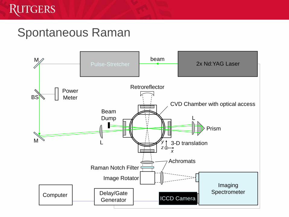
2x Nd:YAG LaserPulse-StretcherM
M
BSPower
Meter
Image Rotator
ICCD Camera
Prism
Imaging
Spectrometer
L
L
Raman Notch Filter
Achromats
Beam
Dump
Retroreflector
x
y
z3-D translation
CVD Chamber with optical access
Delay/Gate
GeneratorComputer
beam
Spontaneous Raman
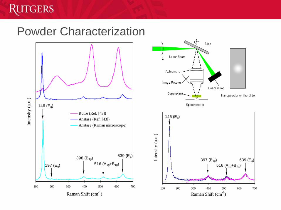
100 200 300 400 500 600 700
Raman Shift (cm-1
)
Inte
nsi
ty (
a.u.)
145 (Eg)
397 (B1g)
516 (A1g+B1g)
639 (Eg)
100 200 300 400 500 600 700
Raman Shift (cm-1
)
Inte
nsi
ty (
a.u.)
Rutile (Ref. [43])
Anatase (Ref. [43])
Anatase (Raman microscope)
146 (Eg)
398 (B1g)
516 (A1g+B1g)
639 (Eg)
197 (Eg)
Powder Characterization
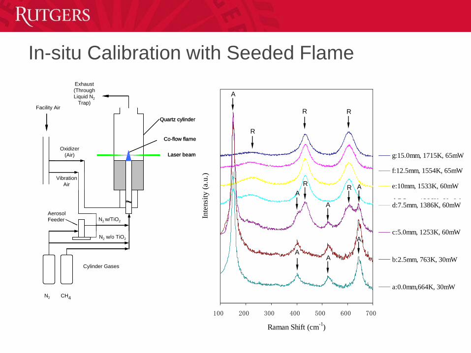
In-situ Calibration with Seeded Flame
N2 w/o TiO2
N2 w/TiO2
Vibration
Air
Oxidizer
(Air)
Facility Air
Cylinder Gases
Exhaust
(Through
Liquid N2
Trap)
CH4N2
Aerosol
Feeder
Quartz cylinder
Co-flow flame
Laser beam
N2 w/o TiO2
N2 w/TiO2
Vibration
Air
Oxidizer
(Air)
Facility Air
Cylinder Gases
Exhaust
(Through
Liquid N2
Trap)
CH4N2
Aerosol
Feeder
Quartz cylinder
Co-flow flame
Laser beam
100 200 300 400 500 600 700
Raman Shift (cm-1
)
Inte
nsi
ty (
a.u
.)
g:15.0mm, 1715K, 65mW
f:12.5mm, 1554K, 65mW
e:10mm, 1533K, 60mW
d:7.5mm, 1386K, 60mW
c:5.0mm, 1253K, 60mW
b:2.5mm, 763K, 30mW
a:0.0mm,664K, 30mW
R R
R
A
AA
A
A
A
ARR
100 200 300 400 500 600 700
Raman Shift (cm-1
)
Inte
nsi
ty (
a.u
.)
g:15.0mm, 1715K, 65mW
f:12.5mm, 1554K, 65mW
e:10mm, 1533K, 60mW
d:7.5mm, 1386K, 60mW
c:5.0mm, 1253K, 60mW
b:2.5mm, 763K, 30mW
a:0.0mm,664K, 30mW
R R
R
A
AA
A
A
A
ARR
100 200 300 400 500 600 700
Raman Shift (cm-1
)
Inte
nsi
ty (
a.u
.)
g:15.0mm, 1715K, 65mW
f:12.5mm, 1554K, 65mW
e:10mm, 1533K, 60mW
d:7.5mm, 1386K, 60mW
c:5.0mm, 1253K, 60mW
b:2.5mm, 763K, 30mW
a:0.0mm,664K, 30mW
R R
R
A
AA
A
A
A
ARR
100 200 300 400 500 600 700
Raman Shift (cm-1
)
Inte
nsi
ty (
a.u
.)
g:15.0mm, 1715K, 65mW
f:12.5mm, 1554K, 65mW
e:10mm, 1533K, 60mW
d:7.5mm, 1386K, 60mW
c:5.0mm, 1253K, 60mW
b:2.5mm, 763K, 30mW
a:0.0mm,664K, 30mW
R R
R
A
AA
A
A
A
ARR
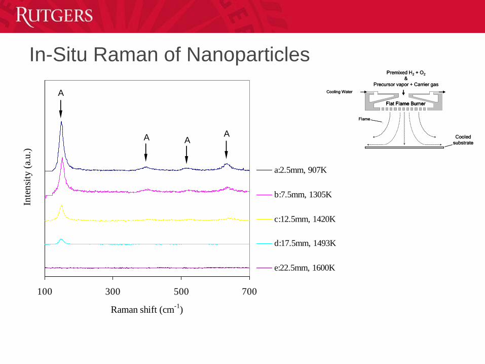
100 300 500 700
Raman shift (cm-1
)
Inte
nsi
ty (
a.u
.)
a:2.5mm, 907K
b:7.5mm, 1305K
c:12.5mm, 1420K
d:17.5mm, 1493K
e:22.5mm, 1600K
A
A AA
Flame
Cooling Water
Cooled
substrate
Flat Flame Burner
Premixed H2 + O2
&
Precursor vapor + Carrier gas
Flame
Cooling Water
Cooled
substrate
Flat Flame BurnerFlat Flame Burner
Premixed H2 + O2
&
Precursor vapor + Carrier gas
In-Situ Raman of Nanoparticles
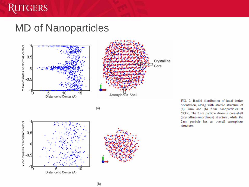
MD of Nanoparticles
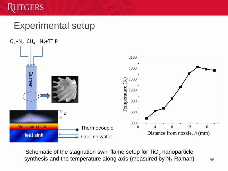
Experimental setup
55
Schematic of the stagnation swirl flame setup for TiO2 nanoparticle
synthesis and the temperature along axis (measured by N2 Raman)
0 4 8 12 16300
600
900
1200
1500
1800
2100
Tem
per
atu
re (
K)
Distance from nozzle, h (mm)
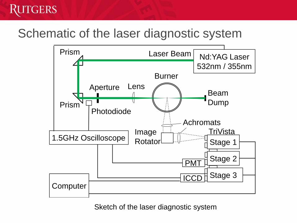
Schematic of the laser diagnostic system
Nd:YAG Laser
532nm / 355nm
ICCD
Prism
Prism
Image
Rotator
Lens
Achromats
Burner
1.5GHz Oscilloscope
Computer
Laser Beam
Beam
DumpPhotodiode
Aperture
PMT
Stage 1
Stage 2
Stage 3
TriVista
Sketch of the laser diagnostic system
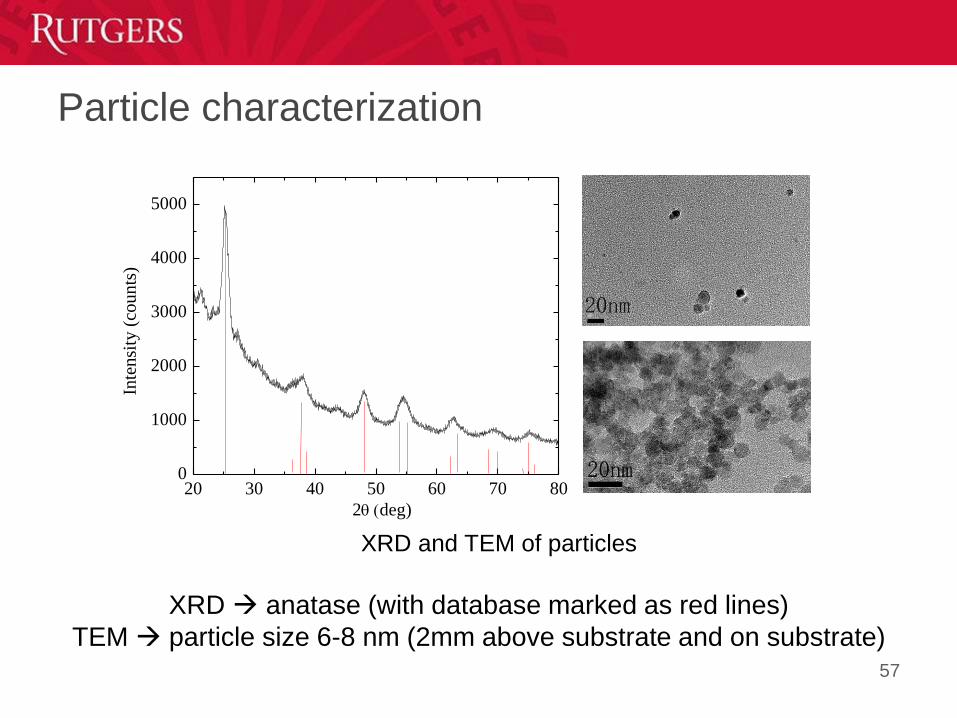
Particle characterization
57
20 30 40 50 60 70 800
1000
2000
3000
4000
5000
Inte
nsi
ty (
counts
)
2(deg)
XRD anatase (with database marked as red lines)
TEM particle size 6-8 nm (2mm above substrate and on substrate)
XRD and TEM of particles
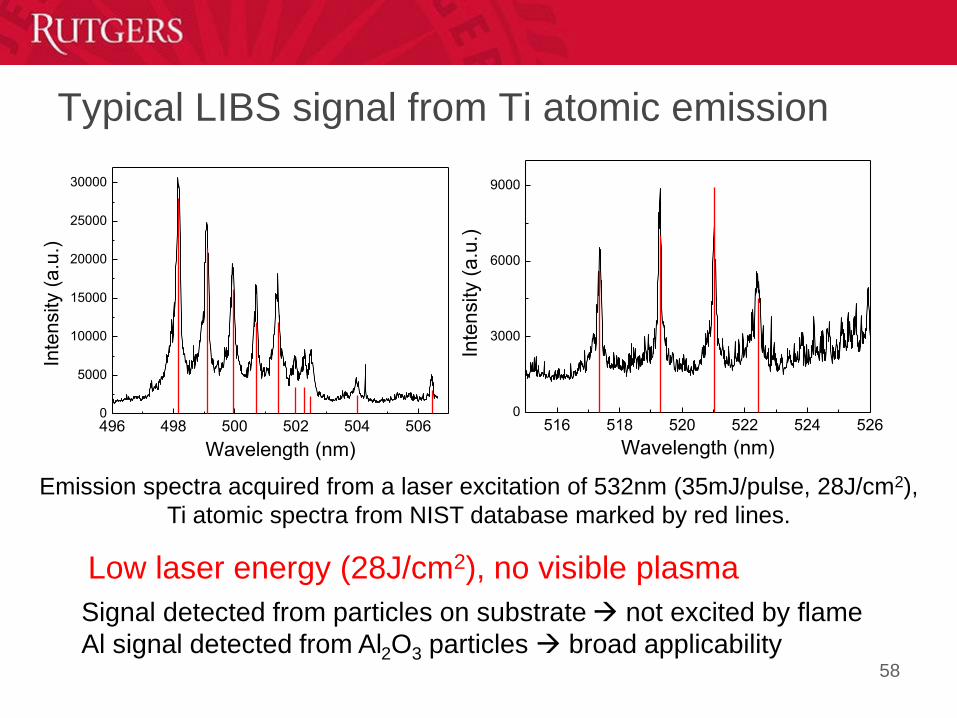
Typical LIBS signal from Ti atomic emission
58
496 498 500 502 504 5060
5000
10000
15000
20000
25000
30000
Inte
nsity (
a.u
.)
Wavelength (nm)
516 518 520 522 524 5260
3000
6000
9000
Inte
nsity (
a.u
.)Wavelength (nm)
Emission spectra acquired from a laser excitation of 532nm (35mJ/pulse, 28J/cm2),
Ti atomic spectra from NIST database marked by red lines.
Signal detected from particles on substrate not excited by flame
Al signal detected from Al2O3 particles broad applicability
Low laser energy (28J/cm2), no visible plasma
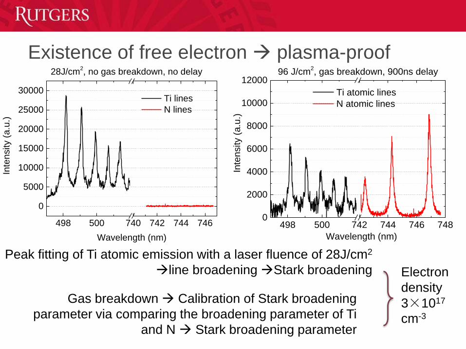
Existence of free electron plasma-proof
Peak fitting of Ti atomic emission with a laser fluence of 28J/cm2
line broadening Stark broadening
Gas breakdown Calibration of Stark broadening
parameter via comparing the broadening parameter of Ti
and N Stark broadening parameter
Electron
density
3×10¹⁷
cm-3
498 500 742 744 746 7480
2000
4000
6000
8000
10000
1200096 J/cm
2, gas breakdown, 900ns delay
Inte
nsity (
a.u
.)Wavelength (nm)
Ti atomic lines
N atomic lines
498 500 740 742 744 746
0
5000
10000
15000
20000
25000
30000
28J/cm2, no gas breakdown, no delay
Inte
nsity (
a.u
.)
Wavelength (nm)
Ti lines
N lines
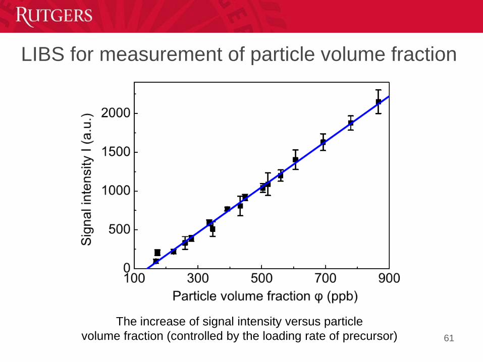
LIBS for measurement of particle volume fraction
61
The increase of signal intensity versus particle
volume fraction (controlled by the loading rate of precursor)
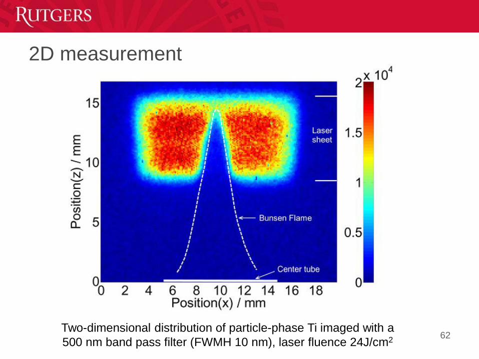
2D measurement
62Two-dimensional distribution of particle-phase Ti imaged with a
500 nm band pass filter (FWMH 10 nm), laser fluence 24J/cm2
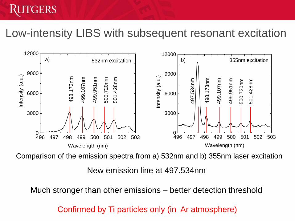
Low-intensity LIBS with subsequent resonant excitation
New emission line at 497.534nm
Much stronger than other emissions – better detection threshold
Comparison of the emission spectra from a) 532nm and b) 355nm laser excitation
496 497 498 499 500 501 502 5030
3000
6000
9000
12000
50
1.4
28
nm
50
0.7
20
nm
49
9.9
51
nm
49
9.1
07
nm
Inte
nsity (
a.u
.)
Wavelength (nm)
49
8.1
73
nm
532nm excitationa)
496 497 498 499 500 501 502 5030
3000
6000
9000
12000
497.5
34nm
Inte
nsity (
a.u
.)
Wavelength (nm)
501.4
28nm
500.7
20nm
499.9
51nm
499.1
07nm
498.1
73nm
b) 355nm excitation
Confirmed by Ti particles only (in Ar atmosphere)
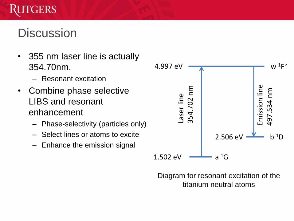
Discussion
• 355 nm laser line is actually
354.70nm.
– Resonant excitation
• Combine phase selective
LIBS and resonant
enhancement
– Phase-selectivity (particles only)
– Select lines or atoms to excite
– Enhance the emission signal
w 1F°
1.502 eV
2.506 eV
4.997 eV
Lase
r lin
e3
54
.70
2 n
m
Emis
sio
n li
ne
49
7.5
34
nm
a 1G
b 1D
Diagram for resonant excitation of the
titanium neutral atoms
Graphene Synthesis
Motivation
• Common methods for graphene/CNT/diamond synthesis include arc discharge, laser ablation, and chemical vapor deposition (CVD)
• But, large-scale applications require synthetic methods that are continuous, energy efficient, and do not require expensive starting materials
• Flame synthesis is scalable and offers potential for high volume production at reduced cost
• Flames readily provide temperatures and carbon speciesneeded for graphene/CNT/diamond growth
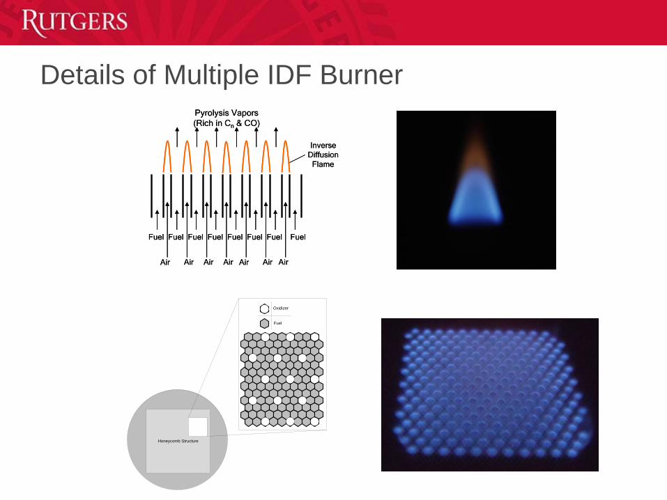
Details of Multiple IDF Burner
Air AirAirAir Air AirAir
Fuel Fuel FuelFuel FuelFuel FuelFuel
Pyrolysis Vapors
(Rich in Cn & CO)
Inverse
Diffusion
Flame
Air AirAirAir Air AirAir
Fuel Fuel FuelFuel FuelFuel FuelFuel
Pyrolysis Vapors
(Rich in Cn & CO)
Inverse
Diffusion
Flame
Honeycomb Structure
Oxidizer
Fuel
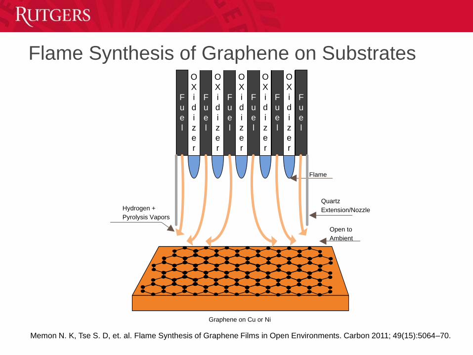
Flame Synthesis of Graphene on SubstratesO
X
i
d
i
z
e
r
F
u
e
l
O
X
i
d
i
z
e
r
F
u
e
l
O
X
i
d
i
z
e
r
F
u
e
l
O
X
i
d
i
z
e
r
F
u
e
l
O
X
i
d
i
z
e
r
F
u
e
l
F
u
e
l
Hydrogen +
Pyrolysis Vapors
Flame
Quartz
Extension/Nozzle
Graphene on Cu or Ni
Open to
Ambient
Memon N. K, Tse S. D, et. al. Flame Synthesis of Graphene Films in Open Environments. Carbon 2011; 49(15):5064–70.
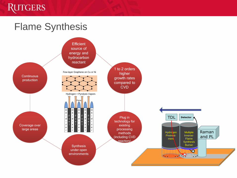
Hydrogen + Pyrolysis Vapors
Few-layer Graphene on Cu or Ni
Flame
O
X
i
d
i
z
e
r
F
u
e
l
O
X
i
d
i
z
e
r
F
u
e
l
O
X
i
d
i
z
e
r
F
u
e
l
O
X
i
d
i
z
e
r
F
u
e
l
O
X
i
d
i
z
e
r
Flame Synthesis
Multiple
Inverse-
Flame
Synthesis
Burner
Hydrogen
Pretreat-
ment
Raman and PL
TDL Detector
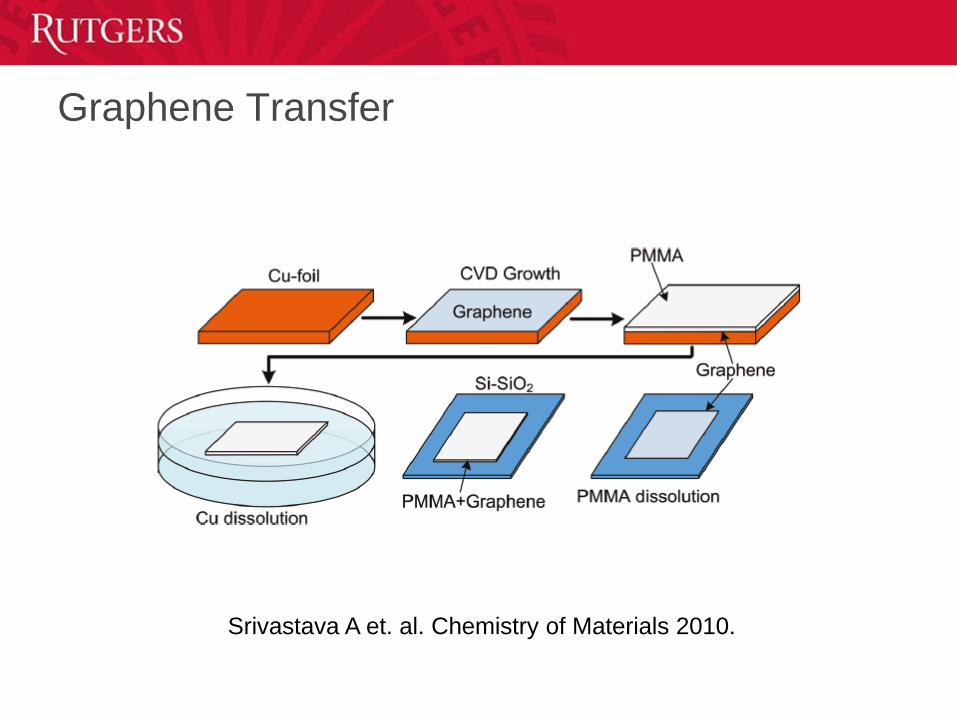
Graphene Transfer
Srivastava A et. al. Chemistry of Materials 2010.
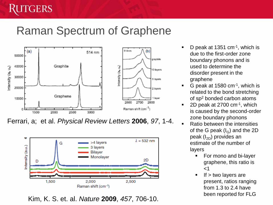
Raman Spectrum of Graphene
Ferrari, a; et al. Physical Review Letters 2006, 97, 1-4.
Kim, K. S. et. al. Nature 2009, 457, 706-10.
D peak at 1351 cm-1, which is
due to the first-order zone
boundary phonons and is
used to determine the
disorder present in the
graphene
G peak at 1580 cm-1, which is
related to the bond stretching
of sp2 bonded carbon atoms
2D peak at 2700 cm-1, which
is caused by the second-order
zone boundary phonons
Ratio between the intensities
of the G peak (IG) and the 2D
peak (I2D) provides an
estimate of the number of
layers
For mono and bi-layer
graphene, this ratio is
<1
If > two layers are
present, ratios ranging
from 1.3 to 2.4 have
been reported for FLG
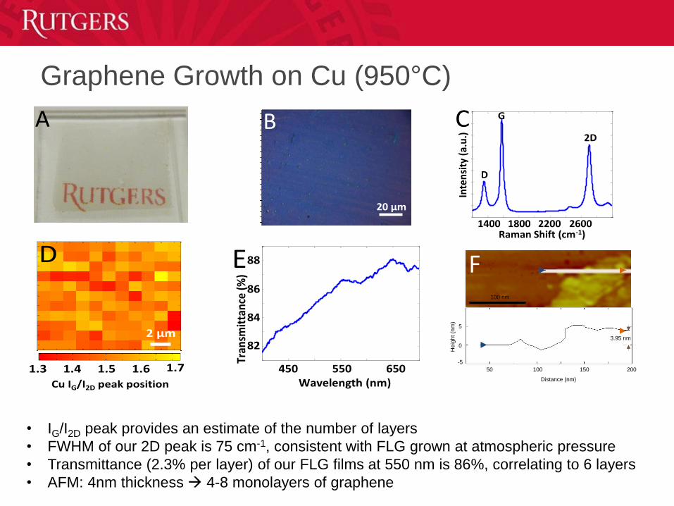
Graphene Growth on Cu (950°C)
A B
20 μm1200 1400 1600 1800 2000 2200 2400 2600 2800 30000
1000
2000
3000
4000
5000
6000
7000
8000
9000
Raman Shift (cm-1)
Inte
nsi
ty (
a.u
.)
1400 1800 26002200
D
G
2D
C
1.71.3
Cu IG/I2D peak position
1.4 1.5 1.6
1 2 3 4 5 6 7 8 9 10 11
1
2
3
4
5
6
7
8
9
10
11
1.3
1.35
1.4
1.45
1.5
1.55
1.6
1.65
1.7
2 μm
D
400 450 500 550 600 650 70081
82
83
84
85
86
87
88
89
Wavelength (nm)550 650
Tran
smit
tanc
e (%
)
82
450
84
86
88E
50 100 150 200
0
-5
5
3.95 nm
Distance (nm)
He
igh
t (n
m)
100 nm
F
• IG/I2D peak provides an estimate of the number of layers
• FWHM of our 2D peak is 75 cm-1, consistent with FLG grown at atmospheric pressure
• Transmittance (2.3% per layer) of our FLG films at 550 nm is 86%, correlating to 6 layers
• AFM: 4nm thickness 4-8 monolayers of graphene
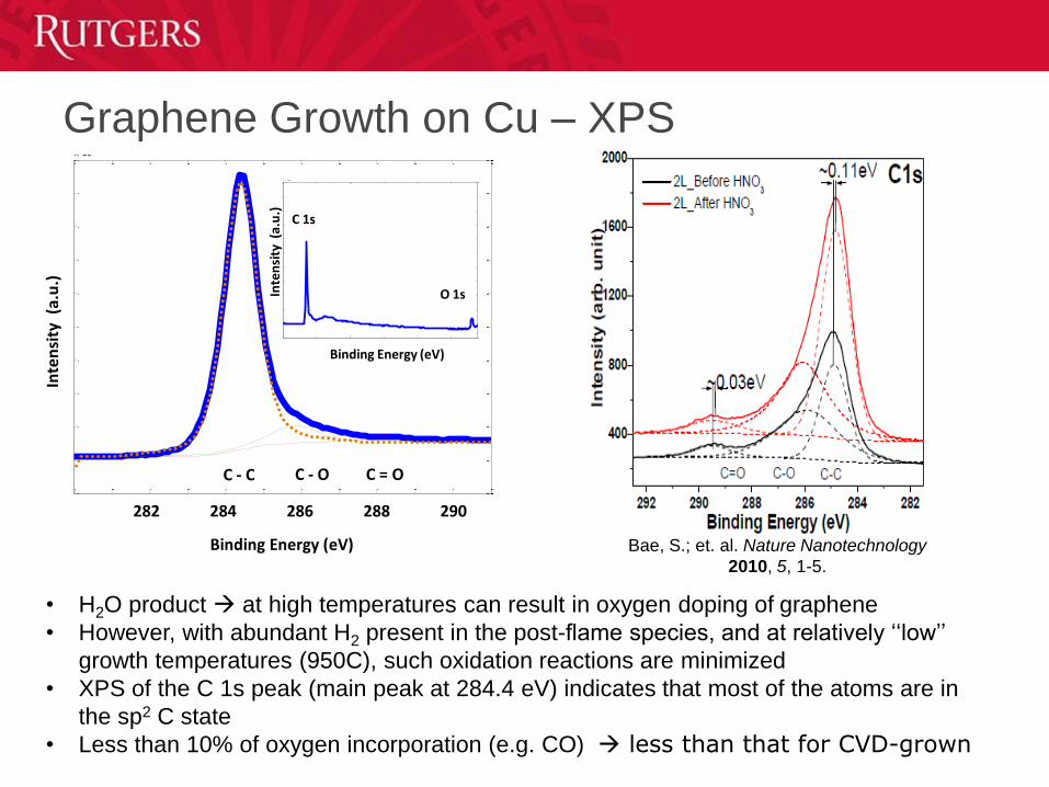
Graphene Growth on Cu – XPS
280 281 282 283 284 285 286 287 288 289 290 2910
1
2
3
4
5
6
7
8
9
10x 10
4
C - C C - O C = O
282 284 286 288 290
Inte
nsi
ty (
a.u
.)
250 300 350 400 450 5000.5
1
1.5
2
2.5
3
3.5
4
4.5
5
5.5
6x 10
5
C 1s
O 1s
Binding Energy (eV)
Binding Energy (eV)
Inte
nsi
ty (
a.u
.)
Bae, S.; et. al. Nature Nanotechnology
2010, 5, 1-5.
• H2O product at high temperatures can result in oxygen doping of graphene
• However, with abundant H2 present in the post-flame species, and at relatively ‘‘low’’
growth temperatures (950C), such oxidation reactions are minimized
• XPS of the C 1s peak (main peak at 284.4 eV) indicates that most of the atoms are in
the sp2 C state
• Less than 10% of oxygen incorporation (e.g. CO) less than that for CVD-grown
Graphene Growth on Ni, Co, Cu-Ni (850°C)
5 1/nm
B
1200 1400 1600 1800 2000 2200 2400 2600 2800 3000
0
2000
4000
6000
8000
10000
12000
14000
16000
18000
1200 1400 1600 1800 2000 2200 2400 2600 2800 3000
-500
0
500
1000
1500
1200 1400 1600 1800 2000 2200 2400 2600 2800 3000-3000
-2000
-1000
0
1000
2000
3000
4000
5000
6000
Inte
nsi
ty (
a.u
.)
1400 1800 26002200
D
G2D
Raman Shift (cm-1)
Cu-Ni Alloy
Co
Ni
a b
150nm
70nm
50nm
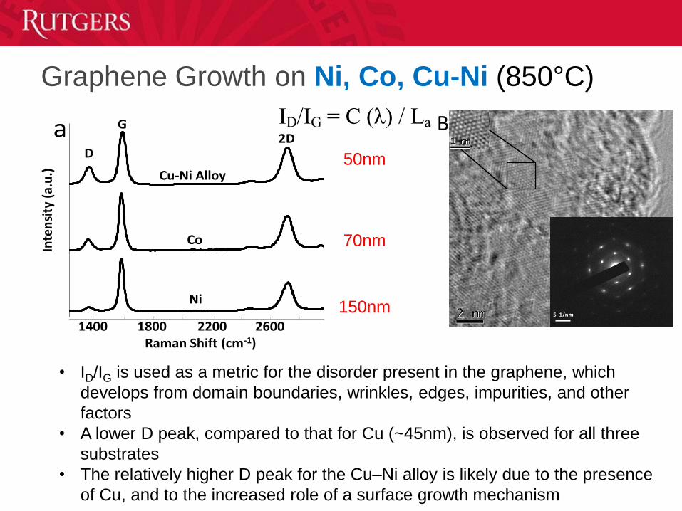
ID/IG = C (λ) / La
• ID/IG is used as a metric for the disorder present in the graphene, which
develops from domain boundaries, wrinkles, edges, impurities, and other
factors
• A lower D peak, compared to that for Cu (~45nm), is observed for all three
substrates
• The relatively higher D peak for the Cu–Ni alloy is likely due to the presence
of Cu, and to the increased role of a surface growth mechanism
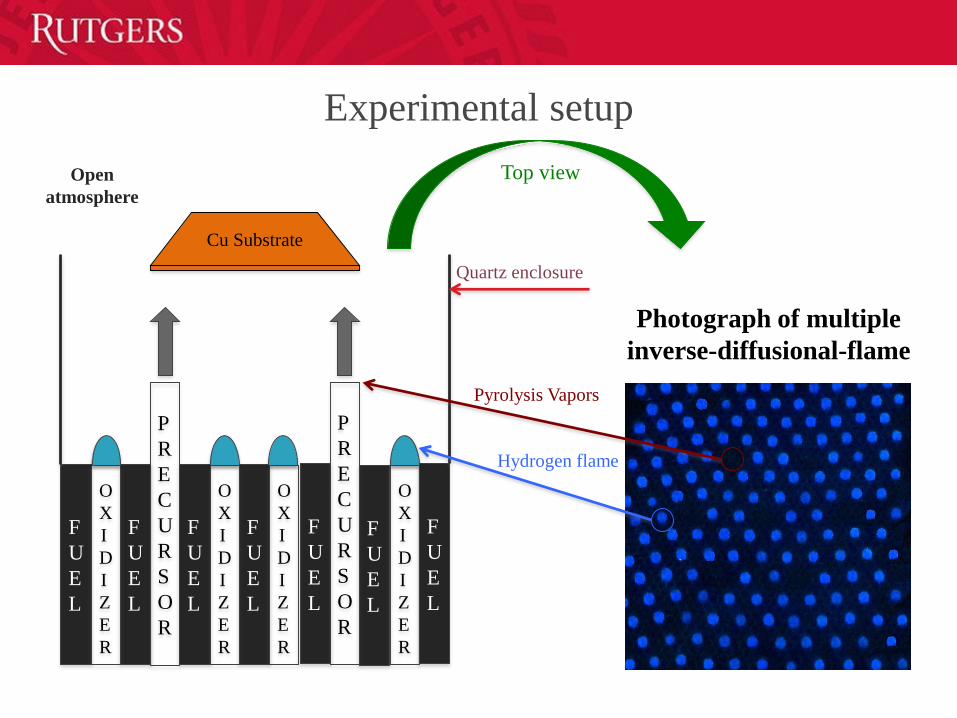
Experimental setup
P
R
E
C
U
R
S
O
R
F
U
E
L
O
X
I
D
I
Z
E
R
F
U
E
L
F
U
E
L
O
X
I
D
I
Z
E
R
F
U
E
L
O
X
I
D
I
Z
E
R
F
U
E
L
F
U
E
L
O
X
I
D
I
Z
E
R
P
R
E
C
U
R
S
O
R
F
U
E
L
Quartz enclosure
Cu Substrate
Pyrolysis Vapors
Photograph of multiple
inverse-diffusional-flame
Hydrogen flame
Open
atmosphere
Top view
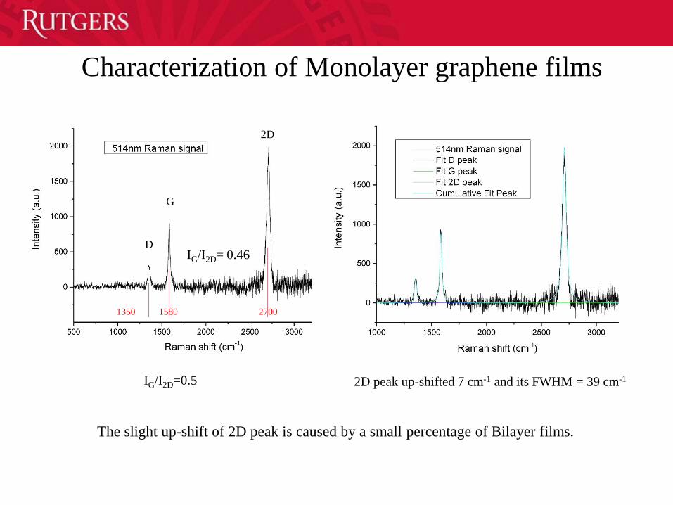
G
D
2D
1350 1580 2700
IG/I2D=0.5 2D peak up-shifted 7 cm-1 and its FWHM = 39 cm-1
Characterization of Monolayer graphene films
The slight up-shift of 2D peak is caused by a small percentage of Bilayer films.
IG/I2D= 0.46

Characterization and Continuous Automation
of an Environmentally Green Primer
Tasks for Paste-Like Material
• Rheology
– Designed device for rheology measurement
– Study on placebo materials Device for filled weight study
– Designed device to fill cups and study weight variability
» First generation device (non energetics) was machined and studied
» Energetics filling device was machined and transferred
» Dosating study on placebo materials completed
• Modeling
– Implemented modeling method using DEM
Task for Slurry Materials
• Rheology
– Implemented technique for rheology measurement
– Started study on placebo materials
• Device for filled weight study
– Designed device to fill cups and study weight variability
» Device was transferred
» Study on placebo materials
• Modeling
– Implemented modeling method using CFD software
Characterization of
Pastes/Wet Powders
• GOAL: To find a placebo material that behaves similarly to
energetic material by matching packing behavior
• Placebo characterization was performed on a small scale (20-
100mg) and a larger scale (4-20g)
• Small scale compressibility experiments were performed at
Rutgers and at Picatinny using sister devices (ARES and
RDA-III)
• A novel small scale attachment was designed by Rutgers and
machined to perform compressibility tests on the ARES and
RDA-III
• Compressibility testing of live material was performed on the
Picatinny RDA-III
Characterization of
Pastes/Wet Powders
• Larger scale placebo characterization was performed at
Rutgers using a Freeman FT4 Powder Rheometer
• Compressibility results obtained by the ARES and RDA-III
were compared to FT4 results to validate the novel cup and
piston design
• Using the FT4, several characterization methods were
implemented to test the flow and packing properties of
placebo material: Compressibility, Permeability, Flow Energy,
Shear
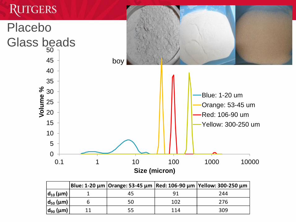
Placebo
Glass beads
0
5
10
15
20
25
30
35
40
45
50
0.1 1 10 100 1000 10000
Vo
lum
e %
Size (micron)
Blue: 1-20 um
Orange: 53-45 um
Red: 106-90 um
Yellow: 300-250 um
Blue: 1-20 µm Orange: 53-45 µm Red: 106-90 µm Yellow: 300-250 µm
d10 (µm) 1 45 91 244
d50 (µm) 6 50 102 276
d90 (µm) 11 55 114 309
boy
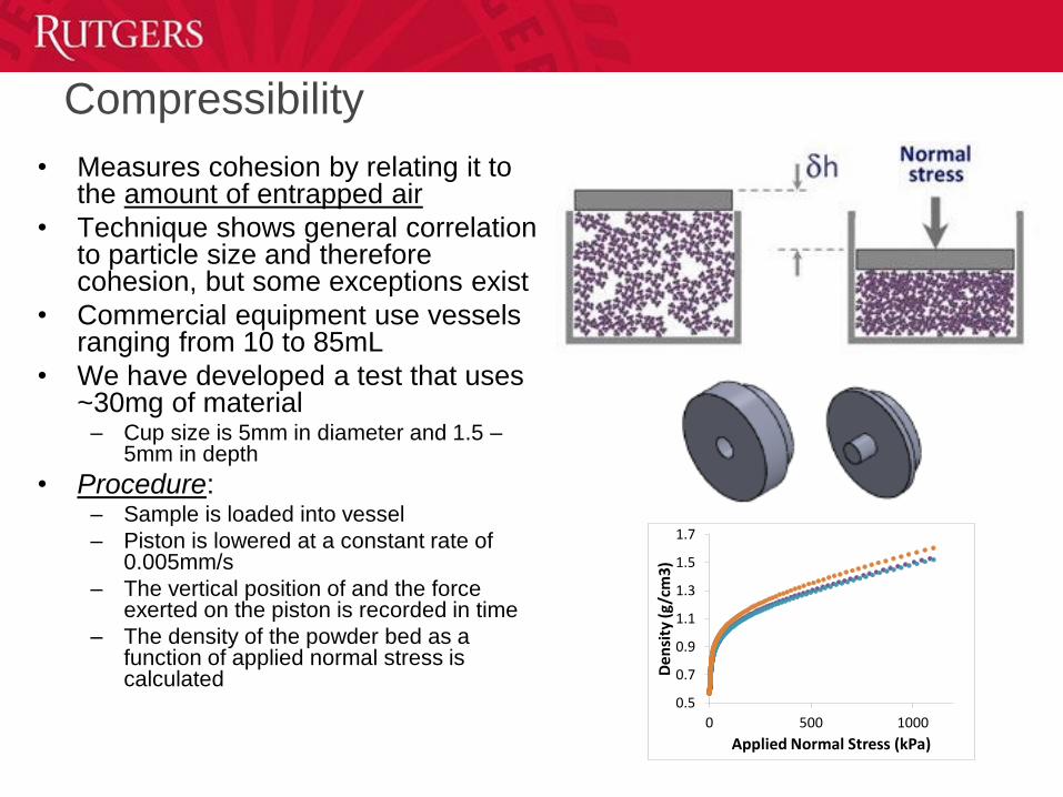
Compressibility
• Measures cohesion by relating it to the amount of entrapped air
• Technique shows general correlation to particle size and therefore cohesion, but some exceptions exist
• Commercial equipment use vessels ranging from 10 to 85mL
• We have developed a test that uses ~30mg of material
– Cup size is 5mm in diameter and 1.5 –5mm in depth
• Procedure:– Sample is loaded into vessel
– Piston is lowered at a constant rate of 0.005mm/s
– The vertical position of and the force exerted on the piston is recorded in time
– The density of the powder bed as a function of applied normal stress is calculated
0.5
0.7
0.9
1.1
1.3
1.5
1.7
0 500 1000
De
nsi
ty (g
/cm
3)
Applied Normal Stress (kPa)
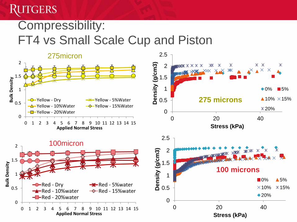
Compressibility:
FT4 vs Small Scale Cup and Piston
0
0.5
1
1.5
2
0 1 2 3 4 5 6 7 8 9 10 11 12 13 14 15
Bu
lk D
ensi
ty
Applied Normal Stress
Yellow - Dry Yellow - 5%WaterYellow - 10%Water Yellow - 15%WaterYellow - 20%Water
0
0.5
1
1.5
2
0 1 2 3 4 5 6 7 8 9 10 11 12 13 14 15
Bu
lk D
ensi
ty
Applied Normal Stress
Red - Dry Red - 5%waterRed - 10%water Red - 15%waterRed - 20%water
275micron
100micron
0
0.5
1
1.5
2
2.5
0 20 40
De
ns
ity (
g/c
m3
)
Stress (kPa)
100 microns
0% 5%
10% 15%
20%
0
0.5
1
1.5
2
2.5
0 20 40
De
ns
ity (
g/c
m3
)
Stress (kPa)
275 microns
0% 5%
10% 15%
20%
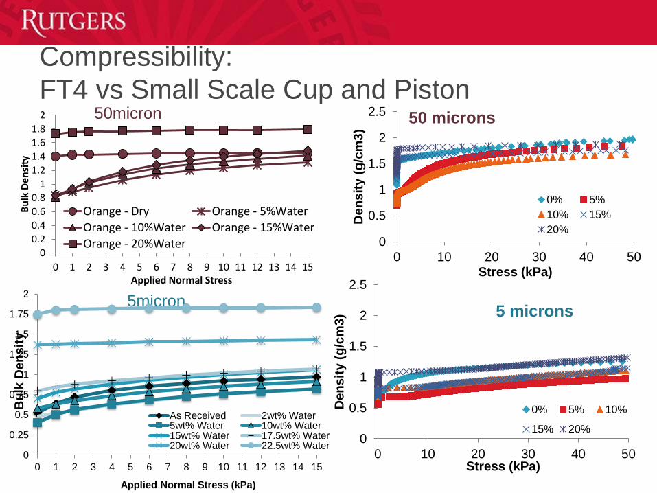
Compressibility:
FT4 vs Small Scale Cup and Piston
0
0.2
0.4
0.6
0.8
1
1.2
1.4
1.6
1.8
2
0 1 2 3 4 5 6 7 8 9 10 11 12 13 14 15
Bu
lk D
ensi
ty
Applied Normal Stress
Orange - Dry Orange - 5%Water
Orange - 10%Water Orange - 15%Water
Orange - 20%Water
50micron
5micron
0
0.5
1
1.5
2
2.5
0 10 20 30 40 50
De
ns
ity (
g/c
m3
)
Stress (kPa)
50 microns
0% 5%
10% 15%
20%
0
0.5
1
1.5
2
2.5
0 10 20 30 40 50
De
ns
ity (
g/c
m3
)
Stress (kPa)
5 microns
0% 5% 10%
15% 20%
0
0.25
0.5
0.75
1
1.25
1.5
1.75
2
0 1 2 3 4 5 6 7 8 9 10 11 12 13 14 15
Bu
lk D
en
sit
y
Applied Normal Stress (kPa)
As Received 2wt% Water5wt% Water 10wt% Water15wt% Water 17.5wt% Water20wt% Water 22.5wt% Water
0
0.2
0.4
0.6
0.8
1
1.2
1.4
1.6
0 5 10 15 20
Bu
lk D
en
sit
y [
g/c
m3]
Piston Pressure [kPa]
DEM
FT4
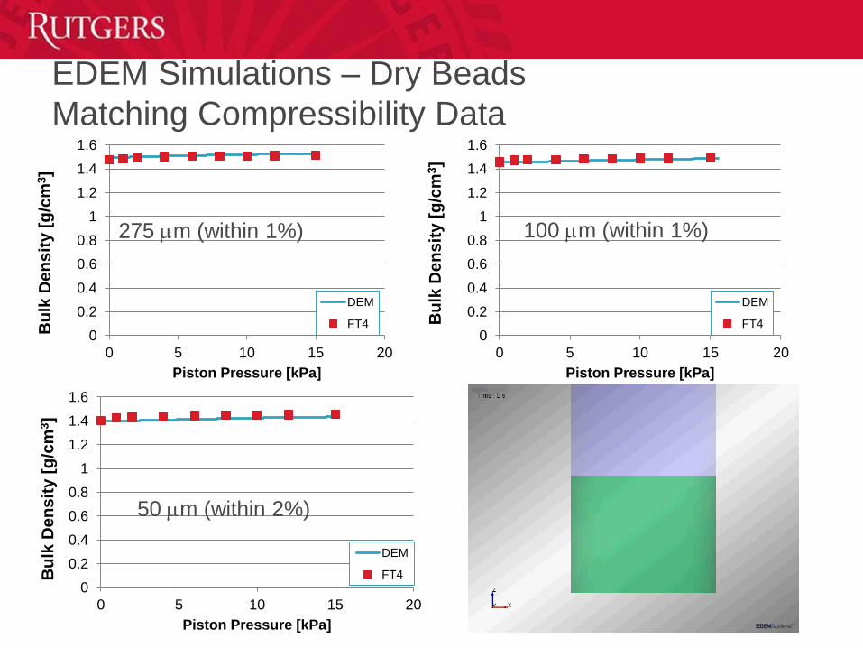
EDEM Simulations – Dry Beads
Matching Compressibility Data
0
0.2
0.4
0.6
0.8
1
1.2
1.4
1.6
0 5 10 15 20
Bu
lk D
en
sit
y [
g/c
m3]
Piston Pressure [kPa]
DEM
FT4
275 mm (within 1%)
0
0.2
0.4
0.6
0.8
1
1.2
1.4
1.6
0 5 10 15 20
Bu
lk D
en
sit
y [
g/c
m3]
Piston Pressure [kPa]
DEM
FT4
100 mm (within 1%)
50 mm (within 2%)
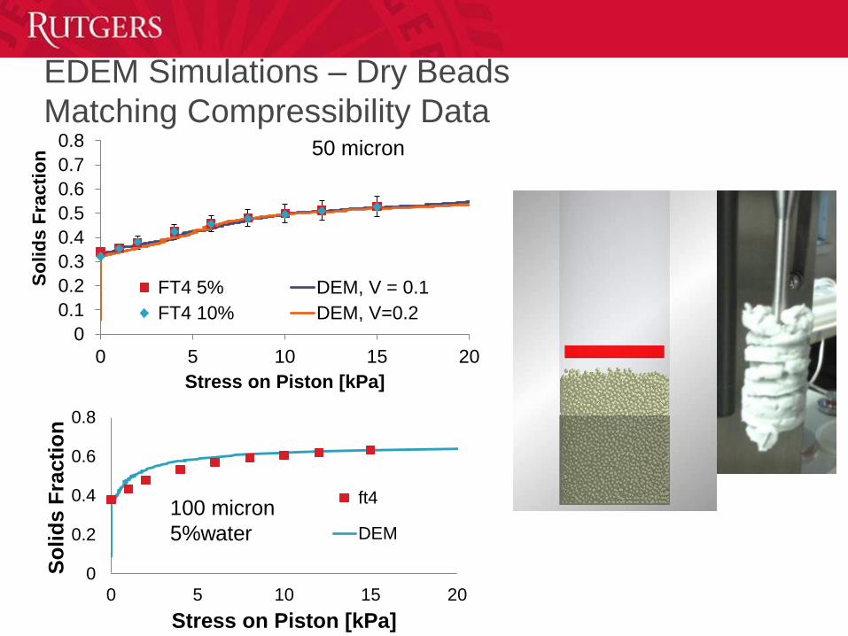
EDEM Simulations – Dry Beads
Matching Compressibility Data
0
0.1
0.2
0.3
0.4
0.5
0.6
0.7
0.8
0 5 10 15 20
So
lid
s F
racti
on
Stress on Piston [kPa]
FT4 5% DEM, V = 0.1
FT4 10% DEM, V=0.2
0
0.2
0.4
0.6
0.8
0 5 10 15 20
So
lid
s F
racti
on
Stress on Piston [kPa]
ft4
DEM
100 micron
5%water
50 micron
Remarks
• The compressibility tests on the novel cup and piston devices
show that the live material match well with multiple placebos
• Cup filling with live material will be performed at Picatinny
• Cup filling experiments at Rutgers will be carried out with the
placebo material
• Simulations show comparable compressibility results and will
be used to perform cup filling simulations
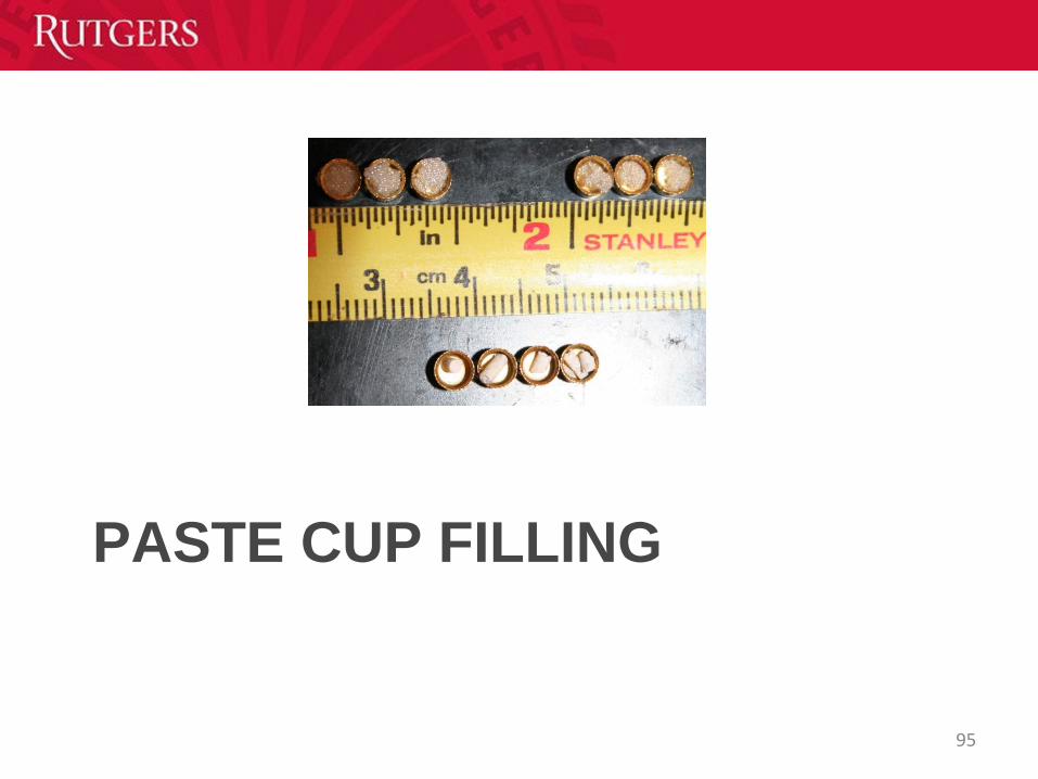
PASTE CUP FILLING
95
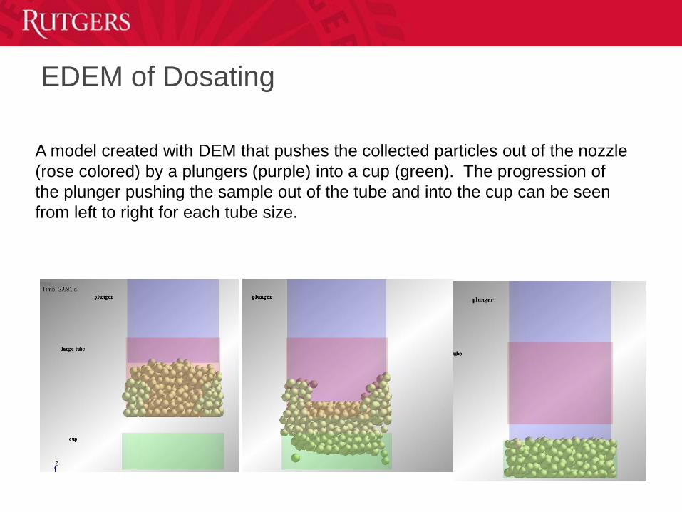
EDEM of Dosating
A model created with DEM that pushes the collected particles out of the nozzle
(rose colored) by a plungers (purple) into a cup (green). The progression of
the plunger pushing the sample out of the tube and into the cup can be seen
from left to right for each tube size.
Placebo Cup Filling Device
Manual tests proved feasibility.
Able to fill 5 cups at a time and up to 100 cups.
Variability will depend heavily on the material properties.97
Machined dosating device
Energetic Cup Filling Device
99

Small Scale Dosating Device
Slurry Rheology
• Placebo viscosity was obtained using low and high viscosity
Brookfield DV-III Rheometers
• ARES Rheometer was used to obtain viscosity measurements
for MIC
• Contact angle and density were also obtained
• Using these properties, simulations can more accurately
represent the system
101
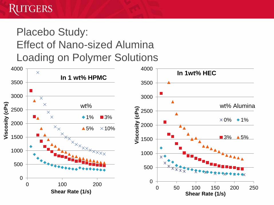
Placebo Study:
Effect of Nano-sized Alumina
Loading on Polymer Solutions
0
500
1000
1500
2000
2500
3000
3500
4000
0 100 200
Vis
co
sit
y (
cP
s)
Shear Rate (1/s)
In 1 wt% HPMC
1% 3%
5% 10%
wt%
0
500
1000
1500
2000
2500
3000
3500
4000
0 50 100 150 200 250
Vis
co
sit
y (
cP
s)
Shear Rate (1/s)
In 1wt% HEC
0% 1%
3% 5%
wt% Alumina
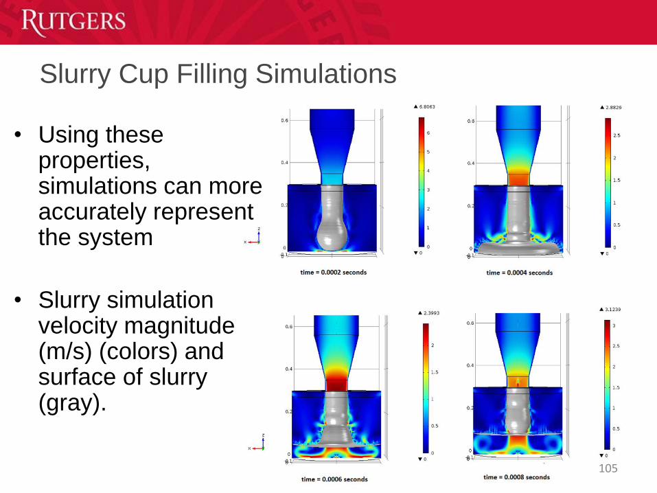
Slurry Cup Filling Simulations
• Using these properties, simulations can more accurately represent the system
• Slurry simulation velocity magnitude (m/s) (colors) and surface of slurry (gray).
105

Remarks
• Rutgers will be performing cup filling experiments with
placebos
• MIC cup filling to be performed by Picatinny
• Cup filling of MIC has been successfully performed by
Innovative Materials and Processes (IMP)
106
Post-docs
– Gang Xiong (synthesis, laser diagnostics)
– Zhizhong Dong (nanowire, nanoparticle synthesis)
– James Scicolone (green primer automation)
Graduate students
– Chris Stout (nanoparticle synthesis)
– Hua Hong (graphene synthesis)
– Bill Mozet (PLD)
– Michelle Lee (MD simulations)
Collaborators
– Keivan Esfarjani
Funding
– National Science Foundation
– Army Research Office
– U.S. Army
– DARPA
– Office of Naval Research
Acknowledgements