Embed Size (px)
Citation preview

SCALAService instructions
GRUNDFOS INSTRUCTIONS

En
glis
h (G
B)
English (GB) Service instructions
Original service instructions
CONTENTSPage
1. Symbols used in this document
The text accompanying the three hazard symbols DANGER, WARNING and CAUTION is structured in the following way:
2. Identification
2.1 Nameplate
Fig. 1 Example of nameplate
1. Symbols used in this document 2
2. Identification 22.1 Nameplate 22.2 Type key 3
3. Service tools 43.1 Standard tools 4
4. Lubricants 4
5. Dismantling and assembly 55.1 General information 55.2 Removing the control box cover 55.3 Removing the pressure tank 55.4 Removing the chamber stack 75.5 Removing the shaft seal 7
6. Fitting the shaft seal 76.1 Fitting the chamber stack 86.2 Fitting the pressure tank 86.3 Fitting the control box cover 9
7. Fault finding the product 107.1 Grundfos Eye operating indications 107.2 Fault resetting 107.3 Fault finding chart 11
8. Exploded view 13
DANGER
Indicates a hazardous situation which, if not avoided, will result in death or serious personal injury.
WARNING
Indicates a hazardous situation which, if not avoided, could result in death or serious personal injury.
CAUTION
Indicates a hazardous situation which, if not avoided, could result in minor or moderate personal injury.
If these instructions are not observed, it may result in malfunction or damage to the equipment.
SIGNAL WORD
Description of hazard
Consequence of ignoring the warning.- Action to avoid the hazard.
TM
06
43
40
20
15
Pos. Description
1 Type designation
2 Product number
3 Serial number
4 Production code, year and week
5 Maximum head
6 Minimum head
7 Rated head
8 Rated flow rate
9 Maximum ambient temperature
10 IP class
11 Maximum operation pressure
12 Maximum liquid temperature
13 Minimum and maximum rated power
14 Model
15 Voltage and frequency
16 Approvals
17 Minimum and maximum rated current
DK-8850 Bjerringbro, DenmarkSCALA2 3-45 AKCHDE
Model A200-240V 50/60HzMade in Serbia
P/N 99999999S/N P/C 1519
HmaxHminHnomQnom
45 m16 m27 m3 m /h3
45 C/
55 CTamb.max
IPX4D
I(A)Min.Max.
P1(W)0.012.8 550
2
Tliq.max/Psyst.max:1MPa
NRP XXX-XXX-XXXXXX
PCS XXXXX.XX.XX 04-6292.2.41-2003LSPr-022-IDN
1
23
4
56789
10
11
13
1415
16
17
12
2
En
gli
sh
(G
B)
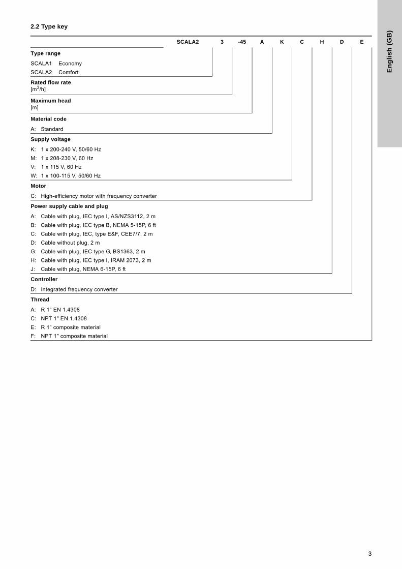
2.2 Type key
SCALA2 3 -45 A K C H D E
Type range
SCALA1 Economy
SCALA2 Comfort
Rated flow rate [m3/h]
Maximum head[m]
Material code
A: Standard
Supply voltage
K: 1 x 200-240 V, 50/60 Hz
M: 1 x 208-230 V, 60 Hz
V: 1 x 115 V, 60 Hz
W: 1 x 100-115 V, 50/60 Hz
Motor
C: High-efficiency motor with frequency converter
Power supply cable and plug
A: Cable with plug, IEC type I, AS/NZS3112, 2 m
B: Cable with plug, IEC type B, NEMA 5-15P, 6 ft
C: Cable with plug, IEC, type E&F, CEE7/7, 2 m
D: Cable without plug, 2 m
G: Cable with plug, IEC type G, BS1363, 2 m
H: Cable with plug, IEC type I, IRAM 2073, 2 m
J: Cable with plug, NEMA 6-15P, 6 ft
Controller
D: Integrated frequency converter
Thread
A: R 1" EN 1.4308
C: NPT 1" EN 1.4308
E: R 1" composite material
F: NPT 1" composite material
3

En
glis
h (G
B)
3. Service tools
3.1 Standard tools
Standard tools
4. LubricantsIf nothing else is specified, all O-rings are to be lubricated with Rocol Sapphire Aqua-Sil.
A B C D
E F
Pos. Range Designation Description Part number
A All Torx screwdriver - -
B All Torque screwdriver 1-6 Nm SV0438
C All Bits kit 5 mm hexagon SV2010
D All Needle-nose pliers - -
E All Ring/open-end spanner M89 - 13 mm SV0055
F Flat-blade screwdriver - -
Product Product number
Rocol Sapphire Aqua-Sil, 1 kg RM2924
Castrol Optimol Paste White T, 0.5 kg V6001176
4
En
gli
sh
(G
B)
5. Dismantling and assembly5.1 General information
5.1.1 Before dismantling
• Disconnect the power supply to the motor.
• Remove the power cable in accordance with local regulations.
• Open a tap to release the pressure in the pipe system.
• Gradually loosen the non-return valve (65a) to release the pressure in the pump.
• Remove the drain plug (7) to drain the pump.
5.1.2 Before assembly
• Always replace gaskets and O-rings when you overhaul the pump.
• Clean and check all parts.
• Replace defective parts.
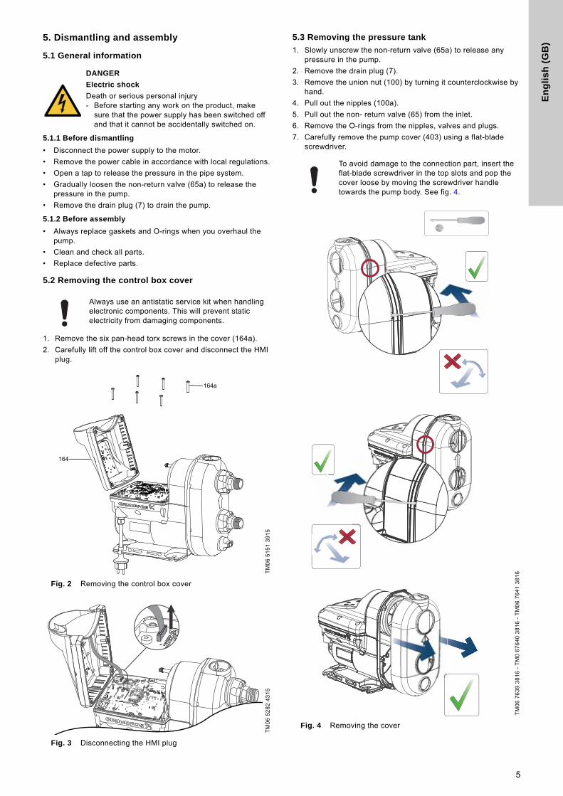
5.2 Removing the control box cover
1. Remove the six pan-head torx screws in the cover (164a).
2. Carefully lift off the control box cover and disconnect the HMI plug.
Fig. 2 Removing the control box cover
Fig. 3 Disconnecting the HMI plug
5.3 Removing the pressure tank
1. Slowly unscrew the non-return valve (65a) to release any pressure in the pump.
2. Remove the drain plug (7).
3. Remove the union nut (100) by turning it counterclockwise by hand.
4. Pull out the nipples (100a).
5. Pull out the non- return valve (65) from the inlet.
6. Remove the O-rings from the nipples, valves and plugs.
7. Carefully remove the pump cover (403) using a flat-blade screwdriver.
Fig. 4 Removing the cover
DANGER
Electric shock
Death or serious personal injury- Before starting any work on the product, make
sure that the power supply has been switched off and that it cannot be accidentally switched on.
Always use an antistatic service kit when handling electronic components. This will prevent static electricity from damaging components.
TM
06
51
51
39
15
TM
06
52
82
43
15
To avoid damage to the connection part, insert the flat-blade screwdriver in the top slots and pop the cover loose by moving the screwdriver handle towards the pump body. See fig. 4.
TM
06
76
39
38
16
- T
M0
67
64
0 3
81
6 -
TM
06
76
41
38
16
5
En
glis
h (G
B)
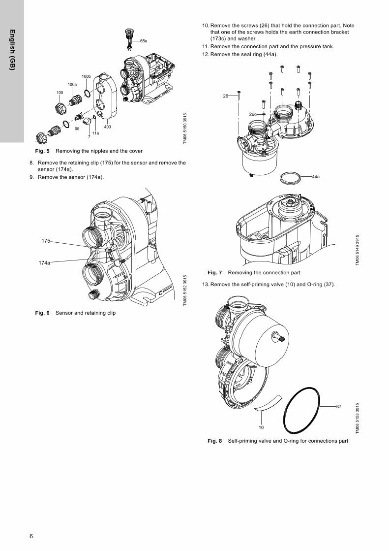
Fig. 5 Removing the nipples and the cover
8. Remove the retaining clip (175) for the sensor and remove the sensor (174a).
9. Remove the sensor (174a).
Fig. 6 Sensor and retaining clip
10. Remove the screws (26) that hold the connection part. Note that one of the screws holds the earth connection bracket (173c) and washer.
11. Remove the connection part and the pressure tank.
12. Remove the seal ring (44a).
Fig. 7 Removing the connection part
13. Remove the self-priming valve (10) and O-ring (37).
Fig. 8 Self-priming valve and O-ring for connections part
TM
06
51
50
39
15
TM
06
51
52
39
15
TM
06
51
49
39
15
TM
06
51
53
39
15
6
En
gli
sh
(G
B)
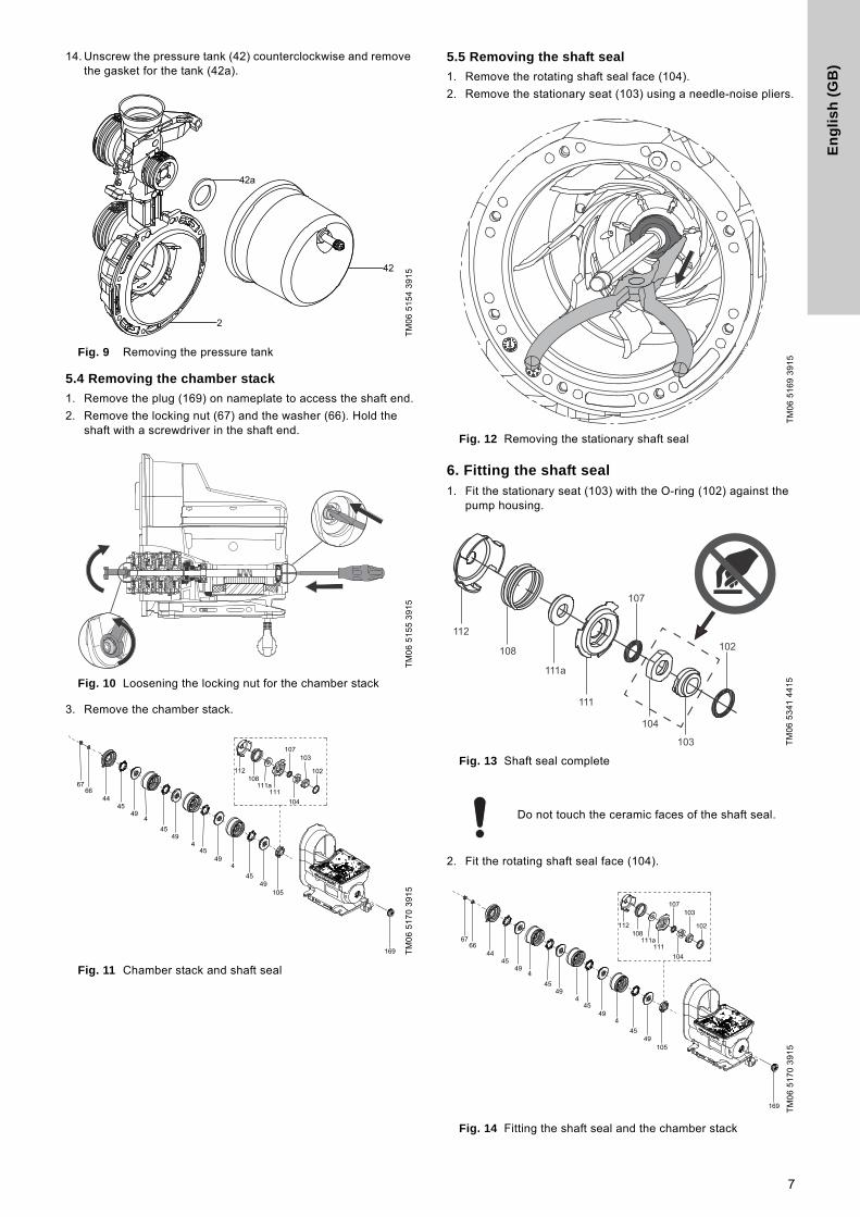
14. Unscrew the pressure tank (42) counterclockwise and remove the gasket for the tank (42a).
Fig. 9 Removing the pressure tank
5.4 Removing the chamber stack
1. Remove the plug (169) on nameplate to access the shaft end.
2. Remove the locking nut (67) and the washer (66). Hold the shaft with a screwdriver in the shaft end.
Fig. 10 Loosening the locking nut for the chamber stack
3. Remove the chamber stack.
Fig. 11 Chamber stack and shaft seal
5.5 Removing the shaft seal
1. Remove the rotating shaft seal face (104).
2. Remove the stationary seat (103) using a needle-noise pliers.
Fig. 12 Removing the stationary shaft seal
6. Fitting the shaft seal1. Fit the stationary seat (103) with the O-ring (102) against the
pump housing.
Fig. 13 Shaft seal complete
2. Fit the rotating shaft seal face (104).
Fig. 14 Fitting the shaft seal and the chamber stack
TM
06
51
54
39
15
TM
06
51
55
39
15
TM
06
51
70
39
15
TM
06
51
69
39
15
TM
06
53
41
44
15
Do not touch the ceramic faces of the shaft seal.
TM
06
51
70
39
15
112
108
104
103
102
107
111a
111
7

En
glis
h (G
B)
6.1 Fitting the chamber stack
1. Fit the impellers (49), the seal (45) and the chambers (4). Fit the seal ring (44a) last.
2. Fit the washer (66) and the locking nut (67) and tighten it to 5 Nm. Hold the shaft end using a screwdriver.
Fig. 15 Tightening the nut of the chamber stack
6.2 Fitting the pressure tank
1. Fit the flat gasket (42a) and screw the pressure tank (42) on to the connection part (2) by hand.
Fig. 16 Fitting the pressure tank
2. Fit the self-priming valve (10) and the O-ring (37).
Fig. 17 Fitting the self-priming valve and the O-ring
3. Check that the self-priming valve is fitted correctly.
Fig. 18 Correct position of the self-priming valve
4. Fit the connection part to the pump housing. Note that one screw holds the earth connection bracket and the washer.
5. Cross-tighten the screws according to table below.
Fig. 19 Fitting the connection part
TM
06
51
58
39
15
TM
06
51
54
39
15
TM
06
51
53
39
15
TM
06
51
49
39
15
SequenceTorque
[Nm]
1
3 ± 0.5
2
3
4
5
6
8
En
gli
sh
(G
B)
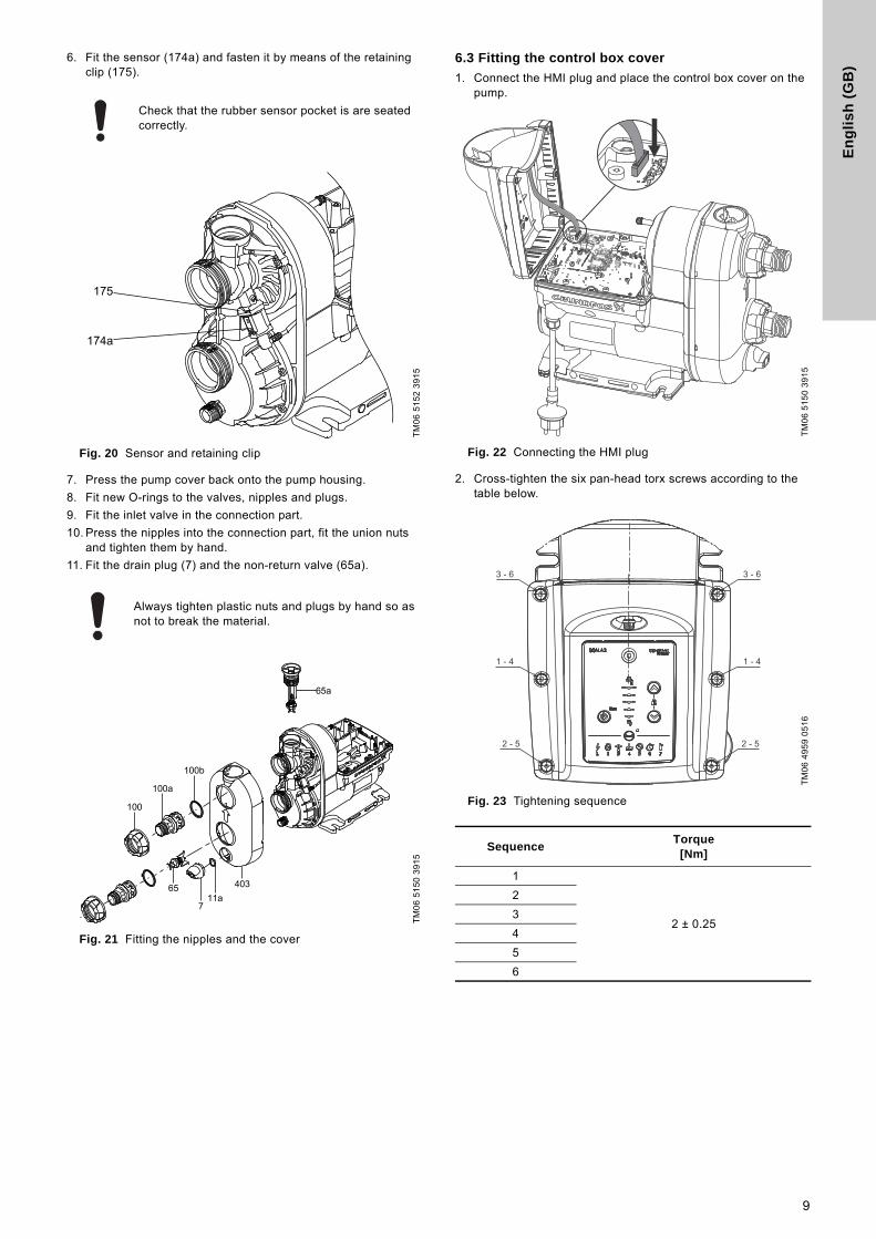
6. Fit the sensor (174a) and fasten it by means of the retaining clip (175).
Fig. 20 Sensor and retaining clip
7. Press the pump cover back onto the pump housing.
8. Fit new O-rings to the valves, nipples and plugs.
9. Fit the inlet valve in the connection part.
10. Press the nipples into the connection part, fit the union nuts and tighten them by hand.
11. Fit the drain plug (7) and the non-return valve (65a).
Fig. 21 Fitting the nipples and the cover
6.3 Fitting the control box cover
1. Connect the HMI plug and place the control box cover on the pump.
Fig. 22 Connecting the HMI plug
2. Cross-tighten the six pan-head torx screws according to the table below.
Fig. 23 Tightening sequence
Check that the rubber sensor pocket is are seated correctly.
TM
06
51
52
39
15
Always tighten plastic nuts and plugs by hand so as not to break the material.
TM
06
51
50
39
15
TM
06
51
50
39
15
TM
06
49
59
05
16
SequenceTorque
[Nm]
1
2 ± 0.25
2
3
4
5
6
3 - 6 3 - 6
2 - 5 2 - 5
1 - 4 1 - 4
9
En
glis
h (G
B)
7. Fault finding the product
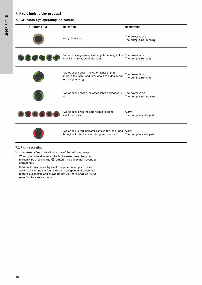
7.1 Grundfos Eye operating indications
7.2 Fault resetting
You can reset a fault indication in one of the following ways:
• When you have eliminated the fault cause, reset the pump manually by pressing the button. The pump then reverts to normal duty.
• If the fault disappears by itself, the pump attempts to reset automatically and the fault indication disappears if automatic reset is successful and provided that you have enabled "Auto reset" in the service menu.
Grundfos Eye Indication Description
No lights are on.The power is off.The pump is not running.
Two opposite green indicator lights running in the direction of rotation of the pump.
The power is on.The pump is running.
Two opposite green indicator lights at a 45 ° angle is the icon used throughout this document for pump running.
The power is on.The pump is running.
Two opposite green indicator lights permanently on.
The power is on.The pump is not running.
Two opposite red indicator lights flashing simultaneously.
Alarm.The pump has stopped.
Two opposite red indicator lights is the icon used throughout this document for pump stopped.
Alarm.The pump has stopped.
10

En
gli
sh
(G
B)
7.3 Fault finding chart
DANGER
Electric shock
Death or serious personal injury- Before starting any work on the product, make
sure that the power supply has been switched off and that it cannot be accidentally switched on.
FaultG
run
dfo
s E
ye
Ind
ica
tor
lig
ht
Au
tom
ati
c r
es
et
Cause Remedy
1. The pump is not running.
- - Power supply failure.
Switch on the power supply.Check the cables and cable connections for defects and loose connections and check for blown fuses in the electrical installation.
YesThe power supply is out of the prescribed voltage range.
Check the power supply and the pump nameplate. Reestablish the power supply within the prescribed voltage range.
No The shaft seal has seized up.Remove the end cover plug and deblock the shaft seal by turning the shaft by means of a screwdriver.
No The pump is blocked by impurities.Contact Grundfos Service if the problem persists.
Yes Dry running.Check the water source, and prime the pump.
NoThe maximum runtime has been exceeded.
Check the installation for leakage and reset the alarm.
NoThe internal non-return valve is defective or blocked in completely or partly open position.
Clean, repair or replace the non-return valve.
2. The pump is running. -
Leakage from the pipes, or the non-return valve is not properly closed due to impurities.
Check and repair the pipes, or clean, repair or replace the non-return valve.
- Small continuous consumption.Check the taps and reconsider the usage pattern (ice machines, water evaporators for air-conditioning, etc.).
-The temperature is below the freezing point.
Consider protecting the pump and the installation against frost.
3. Pump performance is insufficient. - - The pump inlet pressure is too low.
Check the inlet conditions of the pump.
- The pump is undersized.Replace the pump with a bigger pump.
- -The inlet pipe, the inlet strainer or the pump is partly blocked by impurities.
Clean the inlet pipe or the pump.
- - Leakage in the inlet pipe. Repair the inlet pipe.
- - Air in the inlet pipe or the pump.Prime the inlet pipe and the pump.Check the inlet conditions of the pump.
- -The required outlet pressure is too low for the installation.
Increase the pressure setting (arrow up).
YesThe maximum temperature has been exceeded and the pump is running at reduced performance.
Check the cooling conditions. Protect the pump against direct sunlight or any nearby heat sources.
11
En
glis
h (G
B)
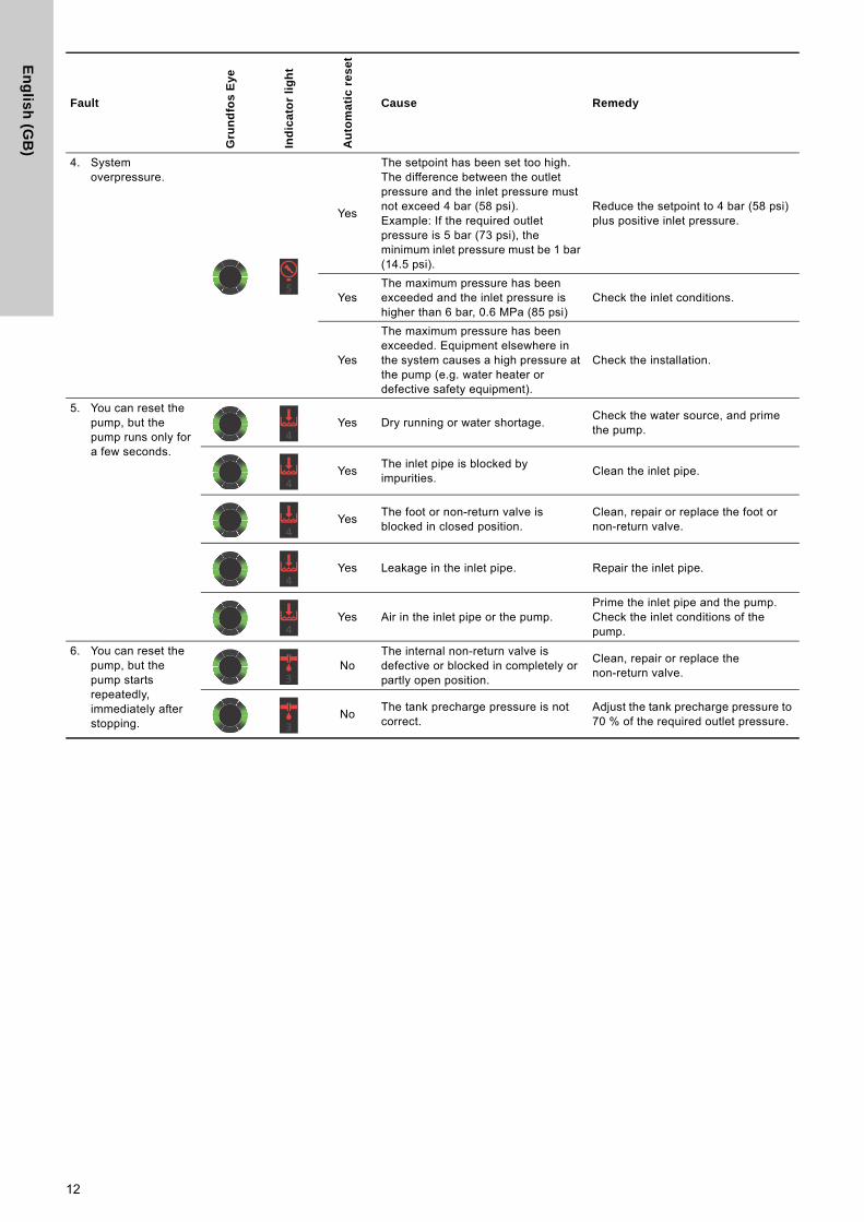
4. System overpressure.
Yes
The setpoint has been set too high. The difference between the outlet pressure and the inlet pressure must not exceed 4 bar (58 psi).Example: If the required outlet pressure is 5 bar (73 psi), the minimum inlet pressure must be 1 bar (14.5 psi).
Reduce the setpoint to 4 bar (58 psi) plus positive inlet pressure.
YesThe maximum pressure has been exceeded and the inlet pressure is higher than 6 bar, 0.6 MPa (85 psi)
Check the inlet conditions.
Yes
The maximum pressure has been exceeded. Equipment elsewhere in the system causes a high pressure at the pump (e.g. water heater or defective safety equipment).
Check the installation.
5. You can reset the pump, but the pump runs only for a few seconds.
Yes Dry running or water shortage.Check the water source, and prime the pump.
YesThe inlet pipe is blocked by impurities.
Clean the inlet pipe.
YesThe foot or non-return valve is blocked in closed position.
Clean, repair or replace the foot or non-return valve.
Yes Leakage in the inlet pipe. Repair the inlet pipe.
Yes Air in the inlet pipe or the pump.Prime the inlet pipe and the pump. Check the inlet conditions of the pump.
6. You can reset the pump, but the pump starts repeatedly, immediately after stopping.
NoThe internal non-return valve is defective or blocked in completely or partly open position.
Clean, repair or replace the non-return valve.
NoThe tank precharge pressure is not correct.
Adjust the tank precharge pressure to 70 % of the required outlet pressure.
Fault
Gru
nd
fos
Ey
e
Ind
ica
tor
lig
ht
Au
tom
ati
c r
es
et
Cause Remedy
12
En
gli
sh
(G
B)
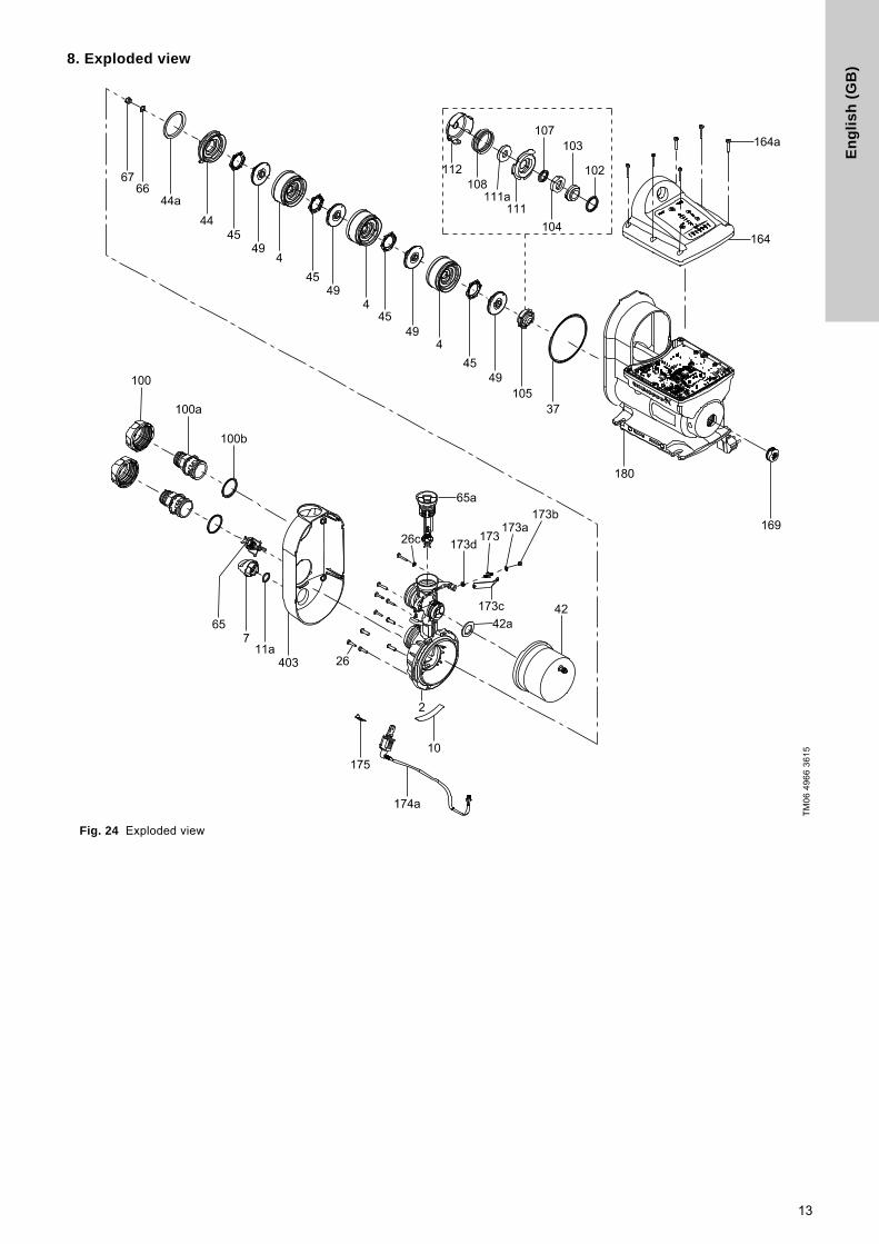
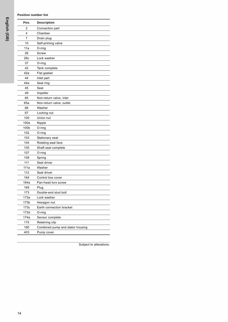
8. Exploded viewFig. 24 Exploded view
TM
06
49
66
36
15
13
En
glis
h (G
B)
Position number list
Subject to alterations.
Pos. Description
2 Connection part
4 Chamber
7 Drain plug
10 Self-priming valve
11a O-ring
26 Screw
26c Lock washer
37 O-ring
42 Tank complete
42a Flat gasket
44 Inlet part
44a Seal ring
45 Seal
49 Impeller
65 Non-return valve, inlet
65a Non-return valve, outlet
66 Washer
67 Locking nut
100 Union nut
100a Nipple
100b O-ring
102 O-ring
103 Stationary seat
104 Rotating seal face
105 Shaft seal complete
107 O-ring
108 Spring
111 Seal driver
111a Washer
112 Seal driver
164 Control box cover
164a Pan-head torx screw
169 Plug
173 Double-end stud bolt
173a Lock washer
173b Hexagon nut
173c Earth connection bracket
173d O-ring
174a Sensor complete
175 Retaining clip
180 Combined pump and stator housing
403 Pump cover
14
Gru
nd
fos
co
mp
anie
s
ArgentinaBombas GRUNDFOS de Argentina S.A.Ruta Panamericana km. 37.500 Centro Industrial Garin1619 Garín Pcia. de B.A.Phone: +54-3327 414 444Telefax: +54-3327 45 3190
AustraliaGRUNDFOS Pumps Pty. Ltd. P.O. Box 2040 Regency Park South Australia 5942 Phone: +61-8-8461-4611 Telefax: +61-8-8340 0155
AustriaGRUNDFOS Pumpen Vertrieb Ges.m.b.H.Grundfosstraße 2 A-5082 Grödig/Salzburg Tel.: +43-6246-883-0 Telefax: +43-6246-883-30
BelgiumN.V. GRUNDFOS Bellux S.A. Boomsesteenweg 81-83 B-2630 Aartselaar Tél.: +32-3-870 7300 Télécopie: +32-3-870 7301
BelarusПредставительство ГРУНДФОС в Минске220125, Минскул. Шафарнянская, 11, оф. 56, БЦ «Порт»Тел.: +7 (375 17) 286 39 72/73Факс: +7 (375 17) 286 39 71E-mail: [email protected]
Bosnia and HerzegovinaGRUNDFOS SarajevoZmaja od Bosne 7-7A,BH-71000 SarajevoPhone: +387 33 592 480Telefax: +387 33 590 465www.ba.grundfos.come-mail: [email protected]
BrazilBOMBAS GRUNDFOS DO BRASILAv. Humberto de Alencar Castelo Branco, 630CEP 09850 - 300São Bernardo do Campo - SPPhone: +55-11 4393 5533Telefax: +55-11 4343 5015
BulgariaGrundfos Bulgaria EOODSlatina DistrictIztochna Tangenta street no. 100BG - 1592 SofiaTel. +359 2 49 22 200Fax. +359 2 49 22 201email: [email protected]
CanadaGRUNDFOS Canada Inc. 2941 Brighton Road Oakville, Ontario L6H 6C9 Phone: +1-905 829 9533 Telefax: +1-905 829 9512
ChinaGRUNDFOS Pumps (Shanghai) Co. Ltd.10F The Hub, No. 33 Suhong RoadMinhang DistrictShanghai 201106PRCPhone: +86 21 612 252 22Telefax: +86 21 612 253 33
CroatiaGRUNDFOS CROATIA d.o.o.Buzinski prilaz 38, BuzinHR-10010 ZagrebPhone: +385 1 6595 400 Telefax: +385 1 6595 499www.hr.grundfos.com
GRUNDFOS Sales Czechia and Slovakia s.r.o.Čajkovského 21779 00 OlomoucPhone: +420-585-716 111
DenmarkGRUNDFOS DK A/S Martin Bachs Vej 3 DK-8850 Bjerringbro Tlf.: +45-87 50 50 50 Telefax: +45-87 50 51 51 E-mail: [email protected]/DK
EstoniaGRUNDFOS Pumps Eesti OÜPeterburi tee 92G11415 TallinnTel: + 372 606 1690Fax: + 372 606 1691
FinlandOY GRUNDFOS Pumput AB Trukkikuja 1 FI-01360 Vantaa Phone: +358-(0) 207 889 500
FrancePompes GRUNDFOS Distribution S.A. Parc d’Activités de Chesnes 57, rue de Malacombe F-38290 St. Quentin Fallavier (Lyon) Tél.: +33-4 74 82 15 15 Télécopie: +33-4 74 94 10 51
GermanyGRUNDFOS GMBHSchlüterstr. 3340699 ErkrathTel.: +49-(0) 211 929 69-0 Telefax: +49-(0) 211 929 69-3799e-mail: [email protected] in Deutschland:e-mail: [email protected]
GreeceGRUNDFOS Hellas A.E.B.E. 20th km. Athinon-Markopoulou Av. P.O. Box 71 GR-19002 Peania Phone: +0030-210-66 83 400 Telefax: +0030-210-66 46 273
Hong KongGRUNDFOS Pumps (Hong Kong) Ltd. Unit 1, Ground floor Siu Wai Industrial Centre 29-33 Wing Hong Street & 68 King Lam Street, Cheung Sha Wan Kowloon Phone: +852-27861706 / 27861741 Telefax: +852-27858664
HungaryGRUNDFOS Hungária Kft.Park u. 8H-2045 Törökbálint, Phone: +36-23 511 110Telefax: +36-23 511 111
IndiaGRUNDFOS Pumps India Private Limited118 Old Mahabalipuram RoadThoraipakkamChennai 600 096Phone: +91-44 2496 6800
IndonesiaPT. GRUNDFOS POMPAGraha Intirub Lt. 2 & 3Jln. Cililitan Besar No.454. Makasar, Jakarta TimurID-Jakarta 13650Phone: +62 21-469-51900Telefax: +62 21-460 6910 / 460 6901
IrelandGRUNDFOS (Ireland) Ltd. Unit A, Merrywell Business ParkBallymount Road LowerDublin 12 Phone: +353-1-4089 800 Telefax: +353-1-4089 830
ItalyGRUNDFOS Pompe Italia S.r.l. Via Gran Sasso 4I-20060 Truccazzano (Milano)Tel.: +39-02-95838112 Telefax: +39-02-95309290 / 95838461
JapanGRUNDFOS Pumps K.K.1-2-3, Shin-Miyakoda, Kita-ku, Hamamatsu431-2103 JapanPhone: +81 53 428 4760Telefax: +81 53 428 5005
KoreaGRUNDFOS Pumps Korea Ltd.6th Floor, Aju Building 679-5Yeoksam-dong, Kangnam-ku, 135-916Seoul, KoreaPhone: +82-2-5317 600Telefax: +82-2-5633 725
LatviaSIA GRUNDFOS Pumps Latvia Deglava biznesa centrsAugusta Deglava ielā 60, LV-1035, Rīga,Tālr.: + 371 714 9640, 7 149 641Fakss: + 371 914 9646
LithuaniaGRUNDFOS Pumps UABSmolensko g. 6LT-03201 VilniusTel: + 370 52 395 430Fax: + 370 52 395 431
MalaysiaGRUNDFOS Pumps Sdn. Bhd.7 Jalan Peguam U1/25Glenmarie Industrial Park40150 Shah AlamSelangor Phone: +60-3-5569 2922Telefax: +60-3-5569 2866
MexicoBombas GRUNDFOS de México S.A. de C.V. Boulevard TLC No. 15Parque Industrial Stiva AeropuertoApodaca, N.L. 66600Phone: +52-81-8144 4000 Telefax: +52-81-8144 4010
NetherlandsGRUNDFOS NetherlandsVeluwezoom 351326 AE AlmerePostbus 220151302 CA ALMERE Tel.: +31-88-478 6336 Telefax: +31-88-478 6332E-mail: [email protected]
New ZealandGRUNDFOS Pumps NZ Ltd.17 Beatrice Tinsley CrescentNorth Harbour Industrial EstateAlbany, AucklandPhone: +64-9-415 3240Telefax: +64-9-415 3250
NorwayGRUNDFOS Pumper A/S Strømsveien 344 Postboks 235, Leirdal N-1011 Oslo Tlf.: +47-22 90 47 00 Telefax: +47-22 32 21 50
PolandGRUNDFOS Pompy Sp. z o.o.ul. Klonowa 23Baranowo k. PoznaniaPL-62-081 PrzeźmierowoTel: (+48-61) 650 13 00Fax: (+48-61) 650 13 50
PortugalBombas GRUNDFOS Portugal, S.A. Rua Calvet de Magalhães, 241Apartado 1079P-2770-153 Paço de ArcosTel.: +351-21-440 76 00Telefax: +351-21-440 76 90
RomaniaGRUNDFOS Pompe România SRLBd. Biruintei, nr 103 Pantelimon county IlfovPhone: +40 21 200 4100Telefax: +40 21 200 4101E-mail: [email protected]
RussiaООО Грундфос Россия109544, г. Москва, ул. Школьная, 39-41, стр. 1Тел. (+7) 495 564-88-00 (495) 737-30-00Факс (+7) 495 564 88 11E-mail [email protected]
Serbia Grundfos Srbija d.o.o.Omladinskih brigada 90b11070 Novi Beograd Phone: +381 11 2258 740Telefax: +381 11 2281 769www.rs.grundfos.com
SingaporeGRUNDFOS (Singapore) Pte. Ltd.25 Jalan Tukang Singapore 619264 Phone: +65-6681 9688 Telefax: +65-6681 9689
SlovakiaGRUNDFOS s.r.o.Prievozská 4D 821 09 BRATISLAVA Phona: +421 2 5020 1426sk.grundfos.com
SloveniaGRUNDFOS LJUBLJANA, d.o.o.Leskoškova 9e, 1122 LjubljanaPhone: +386 (0) 1 568 06 10Telefax: +386 (0)1 568 06 19E-mail: [email protected]
South AfricaGRUNDFOS (PTY) LTDCorner Mountjoy and George Allen RoadsWilbart Ext. 2Bedfordview 2008Phone: (+27) 11 579 4800Fax: (+27) 11 455 6066E-mail: [email protected]
SpainBombas GRUNDFOS España S.A. Camino de la Fuentecilla, s/n E-28110 Algete (Madrid) Tel.: +34-91-848 8800 Telefax: +34-91-628 0465
SwedenGRUNDFOS AB Box 333 (Lunnagårdsgatan 6) 431 24 Mölndal Tel.: +46 31 332 23 000Telefax: +46 31 331 94 60
SwitzerlandGRUNDFOS Pumpen AG Bruggacherstrasse 10 CH-8117 Fällanden/ZH Tel.: +41-44-806 8111 Telefax: +41-44-806 8115
TaiwanGRUNDFOS Pumps (Taiwan) Ltd. 7 Floor, 219 Min-Chuan Road Taichung, Taiwan, R.O.C. Phone: +886-4-2305 0868Telefax: +886-4-2305 0878
ThailandGRUNDFOS (Thailand) Ltd. 92 Chaloem Phrakiat Rama 9 Road,Dokmai, Pravej, Bangkok 10250Phone: +66-2-725 8999Telefax: +66-2-725 8998
TurkeyGRUNDFOS POMPA San. ve Tic. Ltd. Sti.Gebze Organize Sanayi Bölgesi Ihsan dede Caddesi,2. yol 200. Sokak No. 20441490 Gebze/ KocaeliPhone: +90 - 262-679 7979Telefax: +90 - 262-679 7905E-mail: [email protected]
UkraineБізнес Центр ЄвропаСтоличне шосе, 103м. Київ, 03131, Україна Телефон: (+38 044) 237 04 00 Факс.: (+38 044) 237 04 01E-mail: [email protected]
United Arab EmiratesGRUNDFOS Gulf DistributionP.O. Box 16768Jebel Ali Free ZoneDubaiPhone: +971 4 8815 166Telefax: +971 4 8815 136
United KingdomGRUNDFOS Pumps Ltd. Grovebury Road Leighton Buzzard/Beds. LU7 4TL Phone: +44-1525-850000 Telefax: +44-1525-850011
U.S.A.GRUNDFOS Pumps Corporation 17100 West 118th TerraceOlathe, Kansas 66061Phone: +1-913-227-3400 Telefax: +1-913-227-3500
UzbekistanGrundfos Tashkent, Uzbekistan The Repre-sentative Office of Grundfos Kazakhstan in Uzbekistan38a, Oybek street, TashkentТелефон: (+998) 71 150 3290 / 71 150 3291Факс: (+998) 71 150 3292
Addresses Revised 02.09.2016
98979478 1116
ECM: 1197159 The
nam
e G
rund
fos,
the
Gru
ndfo
s lo
go, a
nd b
e t
hin
k i
nn
ov
ate
are
regi
ster
ed tr
adem
arks
ow
ned
by G
rund
fos
Hol
ding
A/S
or G
rund
fos
A/S,
Den
mar
k. A
ll rig
hts
rese
rved
wor
ldw
ide.
© C
opyr
ight
Gru
ndfo
s H
oldi
ng A
/S
www.grundfos.com