Embed Size (px)
Citation preview
SCADAPack 50
Battery-powered GSM data logger
User manual
SCADAPack 50

3NT00341-EN-03-SE-SCADAPack50-User-Manual
SCADAPack 50 Contents
Safety informationSafetyDisclaimer SCADAPack 50 security alert
4444
OverviewPurpose Main features Self-sufficiency Operating principles Operating modes Function indicator lights
6667788
InstallationPrerequisites Internal view of SCADAPack 50 SIM card installation Connectors
9999
10
CommissioningChecklist before starting User configuration Wake-up SCADAPack 50 and activation of local Kervisu connectionTesting the installation Activating a diagnostic SMS sendCase: Pre-configured SCADAPack 50
12121213141617
Local configuration of SCADAPack 50 (Kervisu)Configuration using Kervisu Configuration (GLOBAL-PARAM) screen Channels (V1 to V8) screen Counters screen System screen System message table Network - SMS screen MODBUS-PARAM settings screen Configuration Retrieval/Downloading
18181922262627283031
Frequently asked questions 32
AppendicesSpecifications Factory predefined cable Setting up the infrared/USB interface Setting up the SCADAPack 50 peripheral with Kervisu Local data retrieval Tips for opening your GSM account
33333435373940
Notes 41
4 NT00341-EN-03-SE-SCADAPack50-User-Manual
SCADAPack 50 Safety information
Disclaimer Electrical equipment should be installed, operated, serviced and maintained only by qualified personnel. A qualified person is one who has skills and knowledge related to the construction, installation, and operation of electrical equipment and has received safety training to recognize and avoid the hazards involved.No responsibility is assumed by Schneider Electric for any consequences arising out of the use of this material.
© 2014 Schneider Electric. All rights reserved
SCADAPack 50 security alert NOTICE
HAZARD OF EQUIPMENT MALFUNCTION• The operator should follow all instructions when opening enclosure to perform
any maintenance including battery or SIM card replacement.Failure to follow these instructions can result in equipment damage.
NOTICE:
Safety Read these instructions carefully, and look at the equipment to become familiar with the device before trying to install, operate or maintain it.The following special messages may appear throughout this documentation or on the equipment to advise users of potential hazards or to call attention to information that clarifies or simplifies a procedure.
This is the safety alert symbol. It is used to alert you to potential personal injury hazards. Obey all safety messages that follow this symbol to avoid possible injury or death.
WARNINGWARNING indicates a hazardous situation which, if not avoided, could result in death or serious injury.
CAUTIONCAUTION indicates a hazardous situation which, if not avoided, could result in minor or moderate injury.
NOTICENOTICE is used to address practices not related to physical injury.
5NT00341-EN-03-SE-SCADAPack50-User-Manual
SCADAPack 50 Safety information
WARNINGHAZARD OF EXPLOSIONThe SCADAPack 50 must not be installed in a dangerous zone (explosive atmosphere).Failure to follow these instructions can result in death, serious injury or equipment damage.
ACCEPTABLE USESCADAPack 50 data loggers are intended for use in monitoring applications only. They are not intended for safety-critical applications.
WARNINGHAZARD OF EQUIPMENT OR SYSTEM MALFUNCTION The SCADAPack 50 must not be used in safety-critical applications.Failure to follow these instructions can result in death, serious injuries to personnel or equipment damage.
NOTICEHAZARD OF LOSS OF SIM CARD FUNCTIONALITYBefore installing the SIM card, you should verify its PIN code and if it has been enabled.Failure to follow these instructions can result in the SIM card being locked out permanently. If this occurs, you will need to request the PUK code from the cellular provider.
NOTICEHAZARD OF LOSS OF SIM CARD FUNCTIONALITYDo not insert or extract a SIM card while the SCADAPack 50 is in communication mode. (Indicator light ON or blinking).Failure to follow these instructions can result in equipment damage.
CAUTIONHAZARD OF LOSS OF FUNCTIONALITY• The SCADAPack 50 operates exclusively on Lithium Thionyl Chloride
battery(ies).• Replace only with the same model or an equivalent model proposed by the
manufacturer.• The battery(ies) should be positioned correctly while respecting polarity inside
the socket.Failure to follow these instructions can result in injury or equipment damage.
WARNINGHAZARD OF ELECTRICAL SHOCK• All wiring must be carried out in accordance with industry standards.• Bare wires should never be allowed to come in contact with each other.• The sensors or the power used with the SCADAPack 50 must respect SELV
(Safety Extra Low Voltage) specifications. They should only be installed by qualified personnel.
• This manual covers only the SCADAPack 50. Installation of sensors and other external elements is not included. Contact the manufacturer of these devices to determine the limitations of use of their products. Please refer to the applicable safety requirements on their use.
Failure to follow these instructions can result in death, serious injury or equipment damage.
NOTICEHAZARD OF EQUIPMENT MALFUNCTIONThe total length of sensor wiring must not exceed 3 meters (≈10ft.). The wiring must be twisted pair shielded type to connect the sensor.Failure to follow these instructions can result in equipment measurement malfunction.
6 NT00341-EN-03-SE-SCADAPack50-User-Manual
SCADAPack 50 Overview
PurposeThis user manual outlines the SCADAPack 50 battery-powered GSM data logger, its capabilities, installation, configuration and operation.
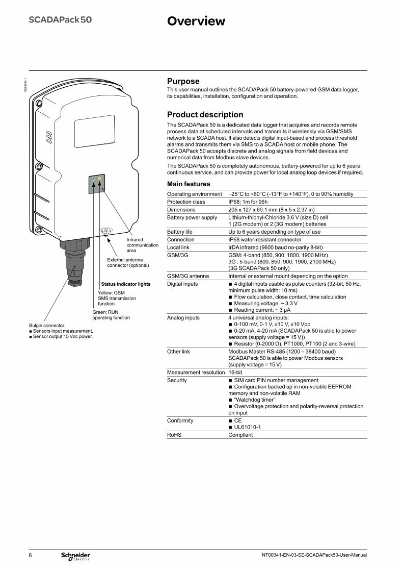
Product descriptionThe SCADAPack 50 is a dedicated data logger that acquires and records remote process data at scheduled intervals and transmits it wirelessly via GSM/SMS network to a SCADA host. It also detects digital input-based and process threshold alarms and transmits them via SMS to a SCADA host or mobile phone. The SCADAPack 50 accepts discrete and analog signals from field devices and numerical data from Modbus slave devices.The SCADAPack 50 is completely autonomous, battery-powered for up to 6 years continuous service, and can provide power for local analog loop devices if required.
Main featuresOperating environment -25°C to +60°C (-13°F to +140°F), 0 to 90% humidityProtection class IP68: 1m for 96hDimensions 205 x 127 x 60.1 mm (8 x 5 x 2.37 in)Battery power supply Lithium-thionyl-Chloride 3.6 V (size D) cell
1 (2G modem) or 2 (3G modem) batteriesBattery life Up to 6 years depending on type of useConnection IP68 water-resistant connectorLocal link IrDA infrared (9600 baud no-parity 8-bit)GSM/3G GSM: 4-band (850, 900, 1800, 1900 MHz)
3G : 5-band (800, 850, 900, 1900, 2100 MHz) (3G SCADAPack 50 only)
GSM/3G antenna Internal or external mount depending on the optionDigital inputs b 4 digital inputs usable as pulse counters (32-bit, 50 Hz,
minimum pulse width: 10 ms) b Flow calculation, close contact, time calculation b Measuring voltage: ~ 3.3 V b Reading current: ~ 3 μA
Analog inputs 4 universal analog inputs: b 0-100 mV, 0-1 V, ±10 V, ±10 Vpp b 0-20 mA, 4-20 mA (SCADAPack 50 is able to power
sensors (supply voltage = 15 V)) b Resistor (0-2000 Ω), PT1000, PT100 (2 and 3-wire)
Other link Modbus Master RS-485 (1200 – 38400 baud) SCADAPack 50 is able to power Modbus sensors (supply voltage = 15 V)
Measurement resolution 16-bitSecurity b SIM card PIN number management
b Configuration backed up in non-volatile EEPROM memory and non-volatile RAM
b “Watchdog timer” b Overvoltage protection and polarity-reversal protection
on inputConformity b CE
b UL61010-1RoHS Compliant
Yellow: GSM SMS transmission function
Green: RUNoperating function
Status indicator lights
DE
5964
2-1
Bulgin connector: ■ Sensors input measurement, ■ Sensor output 15 Vdc power.
Infrared communication area
External antenna connector (optional)
7NT00341-EN-03-SE-SCADAPack50-User-Manual
SCADAPack 50 Overview
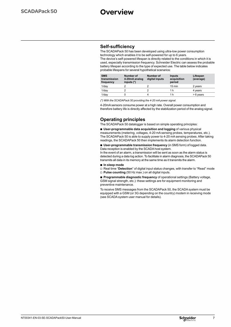
Self-sufficiencyThe SCADAPack 50 has been developed using ultra-low power consumption technology which enables it to be self-powered for up to 6 years.The device’s self-powered lifespan is directly related to the conditions in which it isused, especially transmission frequency. Schneider Electric can assess the probable battery lifespan according to the type of expected use. The table below indicates probable lifespans for several hypothetical scenarios:
SMS transmission frequency
Number of 4-20mA analog inputs (*)
Number of digital inputs
Inputs acquisition period
Lifespan (average)
1/day 2 2 15 min 2 years1/day 2 2 1 h 4 years1/day 0 4 1 h > 6 years
(*) With the SCADAPack 50 providing the 4-20 mA power signal.
4-20mA sensors consume power at a high rate. Overall power consumption and therefore battery life is directly affected by the stabilization period of the analog signal.
Operating principlesThe SCADAPack 50 datalogger is based on simple operating principles:
b User-programmable data acquisition and logging of various physical measurements (metering, voltages, 4-20 mA sensing probes, temperatures, etc.). The SCADAPack 50 is able to supply power to 4-20 mA sensing probes. After taking readings, the SCADAPack 50 then implements its alarm detection function.
b User-programmable transmission frequency (in SMS form) of logged data. Data reception is enabled by the SCADA host system. In the event of an alarm, a transmission will be sent as soon as the alarm status is detected during a data log action. To facilitate in alarm diagnosis, the SCADAPack 50 transmits all data in its memory at the same time as it transmits the alarm.
b In sleep mode v Real time “Detection” of digital input status changes, with transfer to “Read” mode v Pulse counting (50 Hz max.) on all digital inputs. b Programmable diagnostic frequency of operational settings (Battery voltage,
GSM signal strength, etc.): these settings are for equipment monitoring and preventive maintenance.To receive SMS messages from the SCADAPack 50, the SCADA system must be equipped with a GSM (or 3G depending on the country) modem in receiving mode (see SCADA system user manual for details).
8 NT00341-EN-03-SE-SCADAPack50-User-Manual
SCADAPack 50 Overview
Operating modesThe SCADAPack 50 essentially operates in two modes, “Sleep” mode and “Awake” mode. The SCADAPack 50 is an ultra-low power consumption product, and as such is in “sleep” mode for the majority of the time.The device’s functions are activated under the following conditions:
b When the user-programmed time for data acquisition or transmission has been reached
b When an activation magnet is used to awaken the SCADAPack 50 b When a change occurs in the status of a digital input (depending on digital input
configuration).The system cannot be activated by a GSM call, as this would involve a “standby” level of power consumption that would not be compatible with optimizing the battery lifespan. Upon initial start-up or after a reboot caused by removing and re-installing the battery(iies), the device enters an additional “Transport” mode. In this mode, the SCADAPack 50 will not receive nor generate messages and is not able to switch automatically to another mode (“Sleep” or “Awake”). The SCADAPack 50 must then be activated using a magnet.
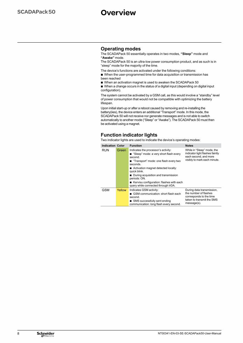
Function indicator lightsTwo indicator lights are used to indicate the device’s operating modes:
Indication Color Function NotesRUN Green Indicates the processor’s activity:
b “Sleep” mode: a very short flash every second.
b “Transport” mode: one flash every two seconds.
b Activation magnet detected locally: quick blink.
b During acquisition and transmission periods: ON.
b Kervisu configuration: flashes with each query while connected through IrDA.
While in “Sleep” mode, the indicator light flashes faintly each second, and more visibly to mark each minute.
GSM Yellow Indicates GSM activity: b GSM communication: short flash each
second. b SMS successfully sent ending
communication: long flash every second.
During data transmission, the number of flashes corresponds to the time taken to transmit the SMS message(s).
9NT00341-EN-03-SE-SCADAPack50-User-Manual
SCADAPack 50 Installation
PrerequisitesPlease refer to the SCADAPack 50 Installation Guide for installation details.In order to operate the SCADAPack 50, you will need:
b Kervisu software version 2.0.6 or higher (available on the CD-ROM provided with the product).
b An activated SIM card with SMS capability. b A USB/IrDA interface (available from Schneider Electric) with appropriate software
drivers (available on CD provided with this product) loaded onto the PC in accordance with the instructions in chapter “Setting up the infrared/USB interface”, and a magnet (typically integrated in the IrDA interface).
DE
5963
5-1
1
2
3
OPEN
LOCK
OPEN
LOCK
OPEN
LOCK
OPEN
LOCK
DE
5963
9-1
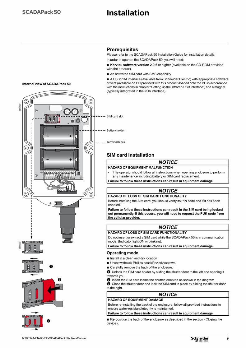
SIM card slot
Terminal block
Battery holder
Internal view of SCADAPack 50
SIM card installationNOTICE
HAZARD OF EQUIPMENT MALFUNCTION• The operator should follow all instructions when opening enclosure to perform
any maintenance including battery or SIM card replacement.Failure to follow these instructions can result in equipment damage.
NOTICEHAZARD OF LOSS OF SIM CARD FUNCTIONALITYBefore installing the SIM card, you should verify its PIN code and if it has been enabled.Failure to follow these instructions can result in the SIM card being locked out permanently. If this occurs, you will need to request the PUK code from the cellular provider.
NOTICEHAZARD OF LOSS OF SIM CARD FUNCTIONALITYDo not insert or extract a SIM card while the SCADAPack 50 is in communication mode. (Indicator light ON or blinking).Failure to follow these instructions can result in equipment damage.
Operating mode b Install in a clean and dry location b Unscrew the six Phillips head (Pozidriv) screws. b Carefully remove the back of the enclosure.
1 Unlock the SIM card holder by sliding the shutter door to the left and opening it towards you.2 Insert the SIM card inside the shutter, oriented as shown in the diagram3 Close the shutter door and lock the SIM card in place by sliding the shutter door
to the right.
NOTICEHAZARD OF EQUIPMENT DAMAGEBefore re-installing the back of the enclosure, follow all provided instructions to ensure water-resistant integrity is maintained.Failure to follow these instructions can result in equipment damage.
b Re-position the back of the enclosure as described in the section «Closing the device».
10 NT00341-EN-03-SE-SCADAPack50-User-Manual
SCADAPack 50 InstallationConnectors
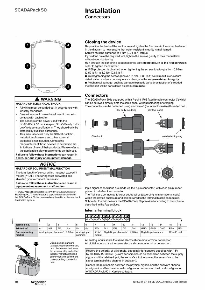
Closing the deviceRe-position the back of the enclosure and tighten the 6 screws in the order illustrated in the diagram to help ensure that water-resistant integrity is maintained.Screws must be tightened to 1 Nm (0.74 lb-ft) torque.If you don’t have the required tool, tighten the screws gently to their manual limit without over-tightening.Run through the tightening sequence once only; do not return to the first screws in order to tighten them further.
b IP68 protection is obtained when tightening the screws to a torque from 0.8 Nm (0.59 lb-ft) to 1.2 Nm (0.88 lb-ft)
b Overtightening the screws (above 1.2 Nm / 0.88 lb-ft) could result in enclosure deterioration and as a consequence a change in the water-resistant integrity.
b Mechanical damage, such as damage to plastic parts or extraction of threaded metal insert will be considered as product misuse.
ConnectorsThe SCADAPack 50 is equipped with a 7-point IP68 fixed female connector (*) which can be screwed directly onto the cable ends, without soldering or crimping. The connector can be detached using a screw-off (counter-clockwise) threaded bolt.
DE
5964
6
231
45
6
7
Gland nut Insert retaining ring
Flex body moulding Contact insert
Input signal connections are made via the 7-pin connector; with each pin number printed in relief on the connector.The 7 pins are connected to color-coded wires (according to international code) within the device enclosure and can be wired to the terminal blocks as required. Schneider Electric delivers the SCADAPack 50 pre-wired according to the scheme described in the Appendices.
Internal terminal block
Terminal no. 1 2 3 4 5 6 7 8 9 10 11 12 13 14 15 16Printed ref. AI1 AI2 AI3 AI4 0V 0V 15V DI1 DI2 DI3 DI4 GND GND GND RS+ RS-Corresponding reading
Analog input channels 1, 2, 3 & 4 Analog input common
+15V output
Digital input channels 1, 2, 3 & 4 Digital input common RS-485 port
All analog inputs share the same electrical common terminal connection.All digital inputs share the same electrical common terminal connection.
Record the polarity of all signals, especially for sensors supplied with 15V by the SCADAPack 50. (2-wire sensors should be connected between the supply signal and the relative input, the sensor’s + to the power, the sensor’s – to the signal terminal of the channel in question).Record the relationship between the physical signals and the software channel configuration. (See the channel configuration screens on the Local configuration of SCADAPack 50 in Kervisu software.
WARNINGHAZARD OF ELECTRICAL SHOCK• All wiring must be carried out in accordance with
industry standards.• Bare wires should never be allowed to come in
contact with each other.• The sensors or the power used with the
SCADAPack 50 must respect SELV (Safety Extra Low Voltage) specifications. They should only be installed by qualified personnel.
• This manual covers only the SCADAPack 50. Installation of sensors and other external elements is not included. Contact the manufacturer of these devices to determine the limitations of use of their products. Please refer to the applicable safety requirements on their use.
Failure to follow these instructions can result in death, serious injury or equipment damage.
NOTICEHAZARD OF EQUIPMENT MALFUNCTIONThe total length of sensor wiring must not exceed 3 meters (≈10ft.). The wiring must be twisted pair shielded type to connect the sensor.Failure to follow these instructions can result in equipment measurement malfunction.
(*) BUCCANEER connector ref.: PX0745/S, Manufacturer: BULGIN (UK). This connector is supplied as standard with the SCADAPack 50 but can also be ordered from the electronic distribution system.
DE
5965
4
1
2
Using a small standard (straight-edge) screwdriver, push the release button on the terminal strip and either insert or retract a stripped connection wire to/from the corresponding connection hole.
1 4
5 6
3 2
11NT00341-EN-03-SE-SCADAPack50-User-Manual
SCADAPack 50 InstallationConnectors
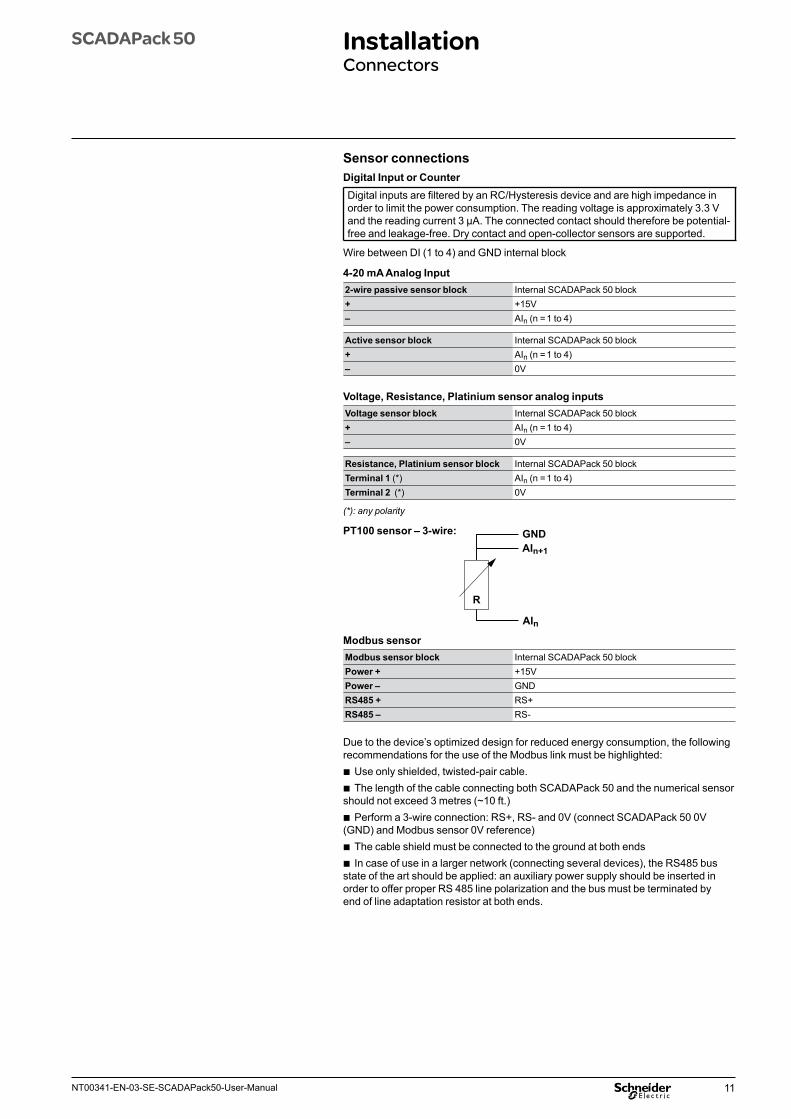
Sensor connectionsDigital Input or Counter Digital inputs are filtered by an RC/Hysteresis device and are high impedance in order to limit the power consumption. The reading voltage is approximately 3.3 V and the reading current 3 μA. The connected contact should therefore be potential-free and leakage-free. Dry contact and open-collector sensors are supported.
Wire between DI (1 to 4) and GND internal block
4-20 mA Analog Input 2-wire passive sensor block Internal SCADAPack 50 block+ +15V– AIn (n = 1 to 4)
Active sensor block Internal SCADAPack 50 block+ AIn (n = 1 to 4) – 0V
Voltage, Resistance, Platinium sensor analog inputs Voltage sensor block Internal SCADAPack 50 block+ AIn (n = 1 to 4) – 0V
Resistance, Platinium sensor block Internal SCADAPack 50 blockTerminal 1 (*) AIn (n = 1 to 4) Terminal 2 (*) 0V
(*): any polarity
PT100 sensor – 3-wire:
R
AIn
AIn+1
GND
Modbus sensor Modbus sensor block Internal SCADAPack 50 blockPower + +15VPower – GNDRS485 + RS+RS485 – RS-
Due to the device’s optimized design for reduced energy consumption, the following recommendations for the use of the Modbus link must be highlighted:
b Use only shielded, twisted-pair cable. b The length of the cable connecting both SCADAPack 50 and the numerical sensor
should not exceed 3 metres (~10 ft.) b Perform a 3-wire connection: RS+, RS- and 0V (connect SCADAPack 50 0V
(GND) and Modbus sensor 0V reference) b The cable shield must be connected to the ground at both ends b In case of use in a larger network (connecting several devices), the RS485 bus
state of the art should be applied: an auxiliary power supply should be inserted in order to offer proper RS 485 line polarization and the bus must be terminated by end of line adaptation resistor at both ends.
12 NT00341-EN-03-SE-SCADAPack50-User-Manual
Checklist before startingFor your activation to run smoothly, you are strongly advised to verify that the following conditions have been met:
b Use only brand new, unused batteries to power the SCADAPack 50; this can be quickly verified using a multimeter, which should give a reading between 3.6 V and 3.7 V. You are strongly advised to attach a date label on each battery when installed.The factory-installed isolation strip located on each battery support must be removed to enable battery power to the SCADAPack 50.
b Ensure that analog input signals are compatible with the analog inputs; particularly the connection polarity when connecting a 4-20 mA sensor that’s powered by the SCADAPack 50 itself.
b Ensure that digital input signals are completely potential free; zero voltage should be measured at the start for each pair (before the connection).
b The SIM card should be correctly inserted in its holder, and locked in place.
Before attempting a configuration and test, verify that: b The device is fitted with a SIM card for which an account has been activated
(this can easily be checked by sending an SMS with the SIM card inserted in a mobile phone).
b A remote station site has been created in the SCADA Host software, with a phone number corresponding to the SIM card inserted in the SCADAPack 50. This is the condition which determines that the data sent by SCADAPack 50 is registered. The SIM card phone number is typically provided by the cell phone service provider when the card is delivered. If you are unsure of the phone number, it will be displayed in the SCADA host when an SMS sent from the SIM card is received by the host.
User configurationThis solution allows all the operating settings to be configured on-site. It requires use of a PC equipped with Kervisu software. Details of the procedure and the different possibilities for configuration are given below.
SCADAPack 50 CommissioningChecklist before startingUser configuration
13NT00341-EN-03-SE-SCADAPack50-User-Manual
SCADAPack 50 CommissioningWake-up SCADAPack 50 and activation of local Kervisu connection
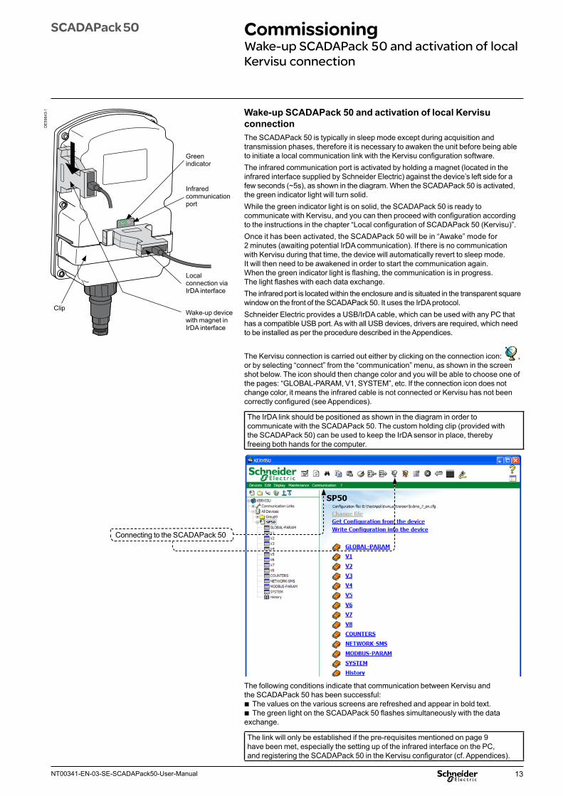
Wake-up SCADAPack 50 and activation of local Kervisu connectionThe SCADAPack 50 is typically in sleep mode except during acquisition and transmission phases, therefore it is necessary to awaken the unit before being able to initiate a local communication link with the Kervisu configuration software. The infrared communication port is activated by holding a magnet (located in the infrared interface supplied by Schneider Electric) against the device’s left side for a few seconds (~5s), as shown in the diagram. When the SCADAPack 50 is activated, the green indicator light will turn solid.While the green indicator light is on solid, the SCADAPack 50 is ready to communicate with Kervisu, and you can then proceed with configuration according to the instructions in the chapter “Local configuration of SCADAPack 50 (Kervisu)”.Once it has been activated, the SCADAPack 50 will be in “Awake” mode for 2 minutes (awaiting potential IrDA communication). If there is no communication with Kervisu during that time, the device will automatically revert to sleep mode. It will then need to be awakened in order to start the communication again. When the green indicator light is flashing, the communication is in progress. The light flashes with each data exchange.The infrared port is located within the enclosure and is situated in the transparent square window on the front of the SCADAPack 50. It uses the IrDA protocol.Schneider Electric provides a USB/IrDA cable, which can be used with any PC that has a compatible USB port. As with all USB devices, drivers are required, which need to be installed as per the procedure described in the Appendices.
The Kervisu connection is carried out either by clicking on the connection icon: , or by selecting “connect” from the “communication” menu, as shown in the screen shot below. The icon should then change color and you will be able to choose one of the pages: “GLOBAL-PARAM, V1, SYSTEM”, etc. If the connection icon does not change color, it means the infrared cable is not connected or Kervisu has not been correctly configured (see Appendices).
The IrDA link should be positioned as shown in the diagram in order to communicate with the SCADAPack 50. The custom holding clip (provided with the SCADAPack 50) can be used to keep the IrDA sensor in place, thereby freeing both hands for the computer.
Connecting to the SCADAPack 50
The following conditions indicate that communication between Kervisu and the SCADAPack 50 has been successful:
b The values on the various screens are refreshed and appear in bold text. b The green light on the SCADAPack 50 flashes simultaneously with the data
exchange.
The link will only be established if the pre-requisites mentioned on page 9 have been met, especially the setting up of the infrared interface on the PC, and registering the SCADAPack 50 in the Kervisu configurator (cf. Appendices).
DE
5964
3-1
Clip
Infrared communication port
Local connection via IrDA interface
Wake-up device with magnet in IrDA interface
Green indicator
14 NT00341-EN-03-SE-SCADAPack50-User-Manual
SCADAPack 50 CommissioningTesting the installation
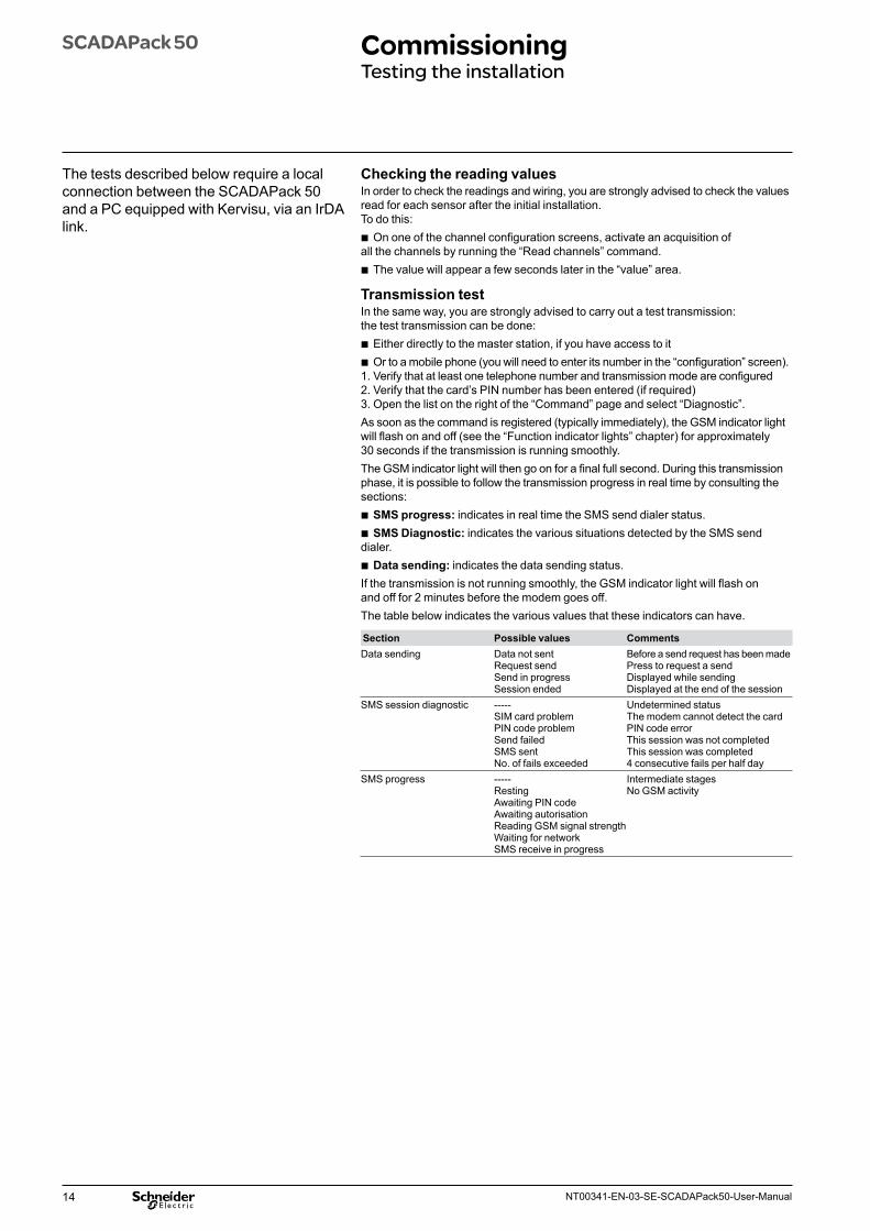
Checking the reading valuesIn order to check the readings and wiring, you are strongly advised to check the values read for each sensor after the initial installation.To do this:
b On one of the channel configuration screens, activate an acquisition of all the channels by running the “Read channels” command.
b The value will appear a few seconds later in the “value” area.
Transmission testIn the same way, you are strongly advised to carry out a test transmission: the test transmission can be done:
b Either directly to the master station, if you have access to it b Or to a mobile phone (you will need to enter its number in the “configuration” screen).
1. Verify that at least one telephone number and transmission mode are configured2. Verify that the card’s PIN number has been entered (if required)3. Open the list on the right of the “Command” page and select “Diagnostic”.As soon as the command is registered (typically immediately), the GSM indicator light will flash on and off (see the “Function indicator lights” chapter) for approximately 30 seconds if the transmission is running smoothly. The GSM indicator light will then go on for a final full second. During this transmission phase, it is possible to follow the transmission progress in real time by consulting the sections:
b SMS progress: indicates in real time the SMS send dialer status. b SMS Diagnostic: indicates the various situations detected by the SMS send
dialer. b Data sending: indicates the data sending status.
If the transmission is not running smoothly, the GSM indicator light will flash on and off for 2 minutes before the modem goes off.The table below indicates the various values that these indicators can have.
Section Possible values CommentsData sending Data not sent
Request send Send in progress Session ended
Before a send request has been made Press to request a send Displayed while sending Displayed at the end of the session
SMS session diagnostic ----- SIM card problem PIN code problem Send failed SMS sent No. of fails exceeded
Undetermined status The modem cannot detect the card PIN code error This session was not completed This session was completed 4 consecutive fails per half day
SMS progress ----- Resting Awaiting PIN code Awaiting autorisation Reading GSM signal strength Waiting for network SMS receive in progress
Intermediate stages No GSM activity
The tests described below require a local connection between the SCADAPack 50 and a PC equipped with Kervisu, via an IrDA link.
15NT00341-EN-03-SE-SCADAPack50-User-Manual
SCADAPack 50 CommissioningTesting the installation
Testing the GSM signal strengthOn-off reading: the value of the GSM signal strength is shown on the configuration screen after an SMS send.Continuous measurement: if you request the action “test GSM strength”, the SCADAPack 50 will read the signal level for 2 minutes; after which the information can be displayed in two different ways:
b On the Configuration screen, in the “GSM level” page b By watching the yellow communication indicator light: the rate at which the indicator
lights up periodically is higher when the signal is stronger. When the light is on more or less continuously, this indicates a strong signal; when it is on for very short periods at a time, it indicates a weak signal.This command can be used to determine the optimum location for the SCADAPack 50 before it is installed, especially on sites where reception is weak.
Other checks Before finishing the installation, you are strongly advised to verify the following items:
b On the Configuration screen: v the current date and time are entered correctly v the data acquisition date and interval are entered, as well as the number of logs
before sending. b On the Channel screens that are in use: v all the required titles have been entered and are different for each channel v all the variables to be logged have been properly selected, in other words that
the type associated with them is set to a value other than “none”.
16 NT00341-EN-03-SE-SCADAPack50-User-Manual
SCADAPack 50 CommissioningActivating a diagnostic SMS send
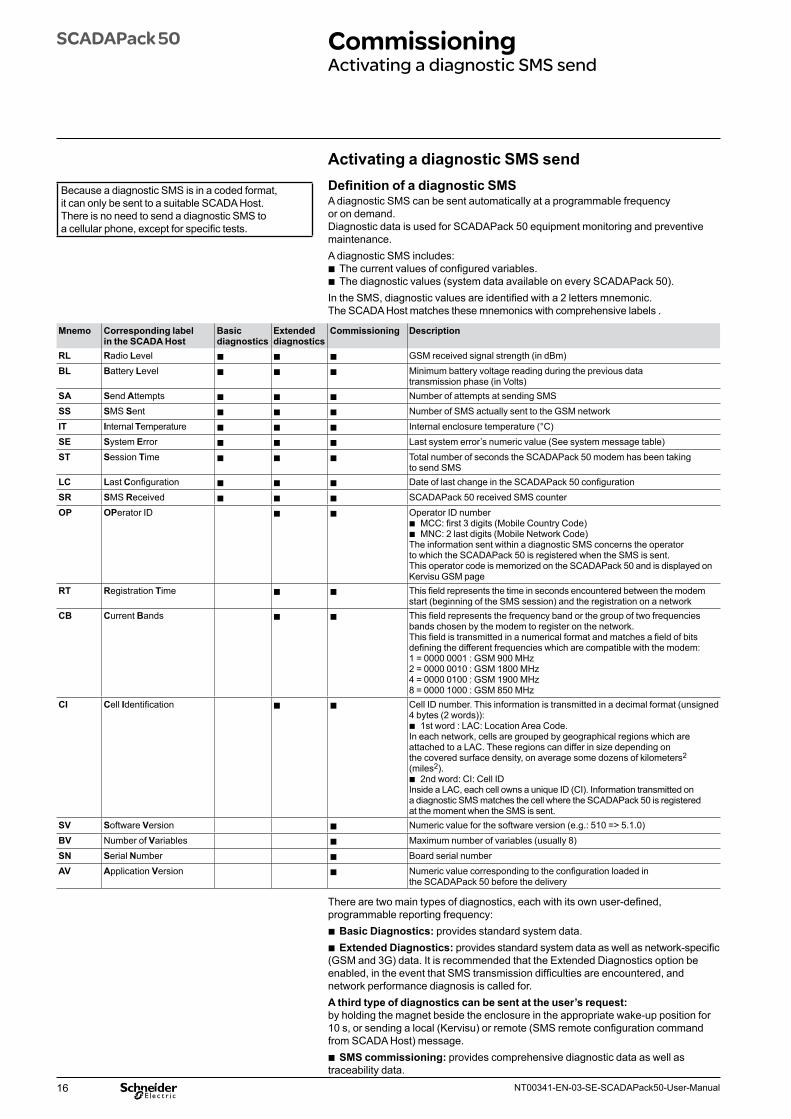
Activating a diagnostic SMS sendDefinition of a diagnostic SMSA diagnostic SMS can be sent automatically at a programmable frequency or on demand.Diagnostic data is used for SCADAPack 50 equipment monitoring and preventive maintenance.A diagnostic SMS includes:
b The current values of configured variables. b The diagnostic values (system data available on every SCADAPack 50).
In the SMS, diagnostic values are identified with a 2 letters mnemonic.The SCADA Host matches these mnemonics with comprehensive labels .
Mnemo Corresponding label in the SCADA Host
Basic diagnostics
Extended diagnostics
Commissioning Description
RL Radio Level b b b GSM received signal strength (in dBm)BL Battery Level b b b Minimum battery voltage reading during the previous data
transmission phase (in Volts)SA Send Attempts b b b Number of attempts at sending SMSSS SMS Sent b b b Number of SMS actually sent to the GSM networkIT Internal Temperature b b b Internal enclosure temperature (°C)SE System Error b b b Last system error’s numeric value (See system message table)ST Session Time b b b Total number of seconds the SCADAPack 50 modem has been taking
to send SMS LC Last Configuration b b b Date of last change in the SCADAPack 50 configurationSR SMS Received b b b SCADAPack 50 received SMS counterOP OPerator ID b b Operator ID number
b MCC: first 3 digits (Mobile Country Code) b MNC: 2 last digits (Mobile Network Code)
The information sent within a diagnostic SMS concerns the operator to which the SCADAPack 50 is registered when the SMS is sent. This operator code is memorized on the SCADAPack 50 and is displayed on Kervisu GSM page
RT Registration Time b b This field represents the time in seconds encountered between the modem start (beginning of the SMS session) and the registration on a network
CB Current Bands b b This field represents the frequency band or the group of two frequencies bands chosen by the modem to register on the network.This field is transmitted in a numerical format and matches a field of bits defining the different frequencies which are compatible with the modem:1 = 0000 0001 : GSM 900 MHz2 = 0000 0010 : GSM 1800 MHz4 = 0000 0100 : GSM 1900 MHz8 = 0000 1000 : GSM 850 MHz
CI Cell Identification b b Cell ID number. This information is transmitted in a decimal format (unsigned 4 bytes (2 words)):
b 1st word : LAC: Location Area Code.In each network, cells are grouped by geographical regions which are attached to a LAC. These regions can differ in size depending on the covered surface density, on average some dozens of kilometers2 (miles2).
b 2nd word: CI: Cell IDInside a LAC, each cell owns a unique ID (CI). Information transmitted on a diagnostic SMS matches the cell where the SCADAPack 50 is registered at the moment when the SMS is sent.
SV Software Version b Numeric value for the software version (e.g.: 510 => 5.1.0)BV Number of Variables b Maximum number of variables (usually 8)SN Serial Number b Board serial numberAV Application Version b Numeric value corresponding to the configuration loaded in
the SCADAPack 50 before the delivery
There are two main types of diagnostics, each with its own user-defined, programmable reporting frequency:
b Basic Diagnostics: provides standard system data. b Extended Diagnostics: provides standard system data as well as network-specific
(GSM and 3G) data. It is recommended that the Extended Diagnostics option be enabled, in the event that SMS transmission difficulties are encountered, and network performance diagnosis is called for.A third type of diagnostics can be sent at the user’s request: by holding the magnet beside the enclosure in the appropriate wake-up position for 10 s, or sending a local (Kervisu) or remote (SMS remote configuration command from SCADA Host) message.
b SMS commissioning: provides comprehensive diagnostic data as well as traceability data.
Because a diagnostic SMS is in a coded format, it can only be sent to a suitable SCADA Host. There is no need to send a diagnostic SMS to a cellular phone, except for specific tests.
17NT00341-EN-03-SE-SCADAPack50-User-Manual
SCADAPack 50 Local configuration of SCADAPack 50 (Kervisu)
Configuring using KervisuThe SCADAPack 50 is configured locally using Kervisu, on a PC equipped with the infrared interface sensor head and USB cable.This guide gives details of:
b The installation procedure for the infrared interface, see Appendices chapter. b The procedure for registering the SCADAPack 50, see Appendices chapter. b The procedure for activating the SCADAPack 50 to communicate with Kervisu,
see the chapter entitled: Commissioning V Wake-up SCADAPack 50 and activation of local Kervisu connection.The actions needed for configuration are carried out under 4 section headings, which correspond to the four screens described below:Configuration (GLOBAL-PARAM) screenThis is where the general operating settings are defined (names, logging and transmission frequency, telephone number, etc.).Channels (V1 to V8) screenThis is where the variables to be logged are defined: their names, types, slope, shift, modes and alarm thresholds.System screenFor the system control (traceability) and system settings.Counters screenWhere the indexes for the digital input counters (DI1 to DI4) can be pre-loaded, whether they are used for pulse counting or time counting.Network and SMS screenWhere the GSM/3G network and SMS configuration parameters are programmed.
Various commands can also be run from these screens, such as SMS send, reading GSM/3G reception signal strength, etc.
Just to remind you…Kervisu is the configuration tool for the SCADAPack 50 data logger.The device’s operational settings can be displayed in Kervisu. This paragraph is intended for users who have not used Kervisu before:Communication can only take place if Kervisu is in connected mode.
(click on the corresponding icon , see the chapter entitled: Commissioning V Wake-up SCADAPack and activation of local Kervisu connection.
18 NT00341-EN-03-SE-SCADAPack50-User-Manual
SCADAPack 50 Local configuration of SCADAPack 50 (Kervisu)Configuration (GLOBAL-PARAM) screen
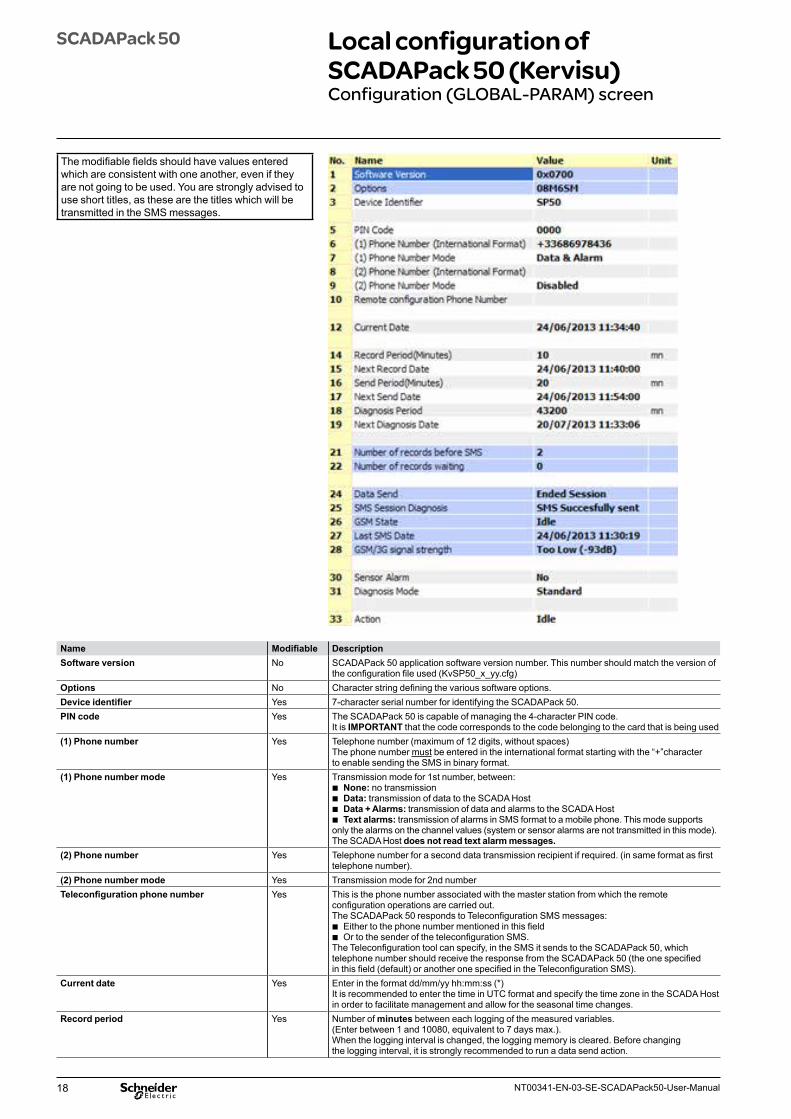
Name Modifiable DescriptionSoftware version No SCADAPack 50 application software version number. This number should match the version of
the configuration file used (KvSP50_x_yy.cfg)Options No Character string defining the various software options.Device identifier Yes 7-character serial number for identifying the SCADAPack 50.PIN code Yes The SCADAPack 50 is capable of managing the 4-character PIN code.
It is IMPORTANT that the code corresponds to the code belonging to the card that is being used(1) Phone number Yes Telephone number (maximum of 12 digits, without spaces)
The phone number must be entered in the international format starting with the “+”character to enable sending the SMS in binary format.
(1) Phone number mode Yes Transmission mode for 1st number, between: b None: no transmission b Data: transmission of data to the SCADA Host b Data + Alarms: transmission of data and alarms to the SCADA Host b Text alarms: transmission of alarms in SMS format to a mobile phone. This mode supports
only the alarms on the channel values (system or sensor alarms are not transmitted in this mode). The SCADA Host does not read text alarm messages.
(2) Phone number Yes Telephone number for a second data transmission recipient if required. (in same format as first telephone number).
(2) Phone number mode Yes Transmission mode for 2nd numberTeleconfiguration phone number Yes This is the phone number associated with the master station from which the remote
configuration operations are carried out.The SCADAPack 50 responds to Teleconfiguration SMS messages:
b Either to the phone number mentioned in this field b Or to the sender of the teleconfiguration SMS.
The Teleconfiguration tool can specify, in the SMS it sends to the SCADAPack 50, which telephone number should receive the response from the SCADAPack 50 (the one specified in this field (default) or another one specified in the Teleconfiguration SMS).
Current date Yes Enter in the format dd/mm/yy hh:mm:ss (*)It is recommended to enter the time in UTC format and specify the time zone in the SCADA Host in order to facilitate management and allow for the seasonal time changes.
Record period Yes Number of minutes between each logging of the measured variables.(Enter between 1 and 10080, equivalent to 7 days max.).When the logging interval is changed, the logging memory is cleared. Before changing the logging interval, it is strongly recommended to run a data send action.
The modifiable fields should have values entered which are consistent with one another, even if they are not going to be used. You are strongly advised to use short titles, as these are the titles which will be transmitted in the SMS messages.
19NT00341-EN-03-SE-SCADAPack50-User-Manual
SCADAPack 50 Local configuration of SCADAPack 50 (Kervisu)Configuration (GLOBAL-PARAM) screen
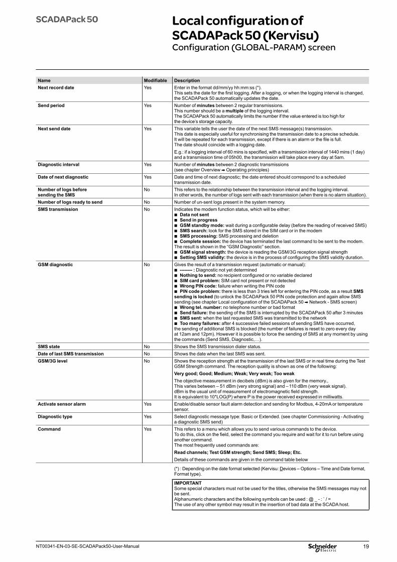
Name Modifiable DescriptionNext record date Yes Enter in the format dd/mm/yy hh:mm:ss (*).
This sets the date for the first logging. After a logging, or when the logging interval is changed, the SCADAPack 50 automatically updates the date.
Send period Yes Number of minutes between 2 regular transmissions. This number should be a multiple of the logging interval. The SCADAPack 50 automatically limits the number if the value entered is too high for the device’s storage capacity.
Next send date Yes This variable tells the user the date of the next SMS message(s) transmission. This date is especially useful for synchronising the transmission date to a precise schedule. It will be repeated for each transmission, except if there is an alarm or the file is full.The date should coincide with a logging date.E.g.: if a logging interval of 60 mins is specified, with a transmission interval of 1440 mins (1 day) and a transmission time of 05h00, the transmission will take place every day at 5am.
Diagnostic interval Yes Number of minutes between 2 diagnostic transmissions (see chapter Overview V Operating principles)
Date of next diagnostic Yes Date and time of next diagnostic; the date entered should correspond to a scheduled transmission date.
Number of logs before sending the SMS
No This refers to the relationship between the transmission interval and the logging interval. In other words, the number of logs sent with each transmission (when there is no alarm situation).
Number of logs ready to send No Number of un-sent logs present in the system memory.SMS transmission No Indicates the modem function status, which will be either:
b Data not sent b Send in progress b GSM standby mode: wait during a configurable delay (before the reading of received SMS) b SMS search: look for the SMS stored in the SIM card or in the modem b SMS processing: SMS processing and deletion b Complete session: the device has terminated the last command to be sent to the modem.
The result is shown in the “GSM Diagnostic” section. b GSM signal strength: the device is reading the GSM/3G reception signal strength b Setting SMS validity: the device is in the process of configuring the SMS validity duration.
GSM diagnostic No Gives the result of a transmission request (automatic or manual): b -------- : Diagnostic not yet determined b Nothing to send: no recipient configured or no variable declared b SIM card problem: SIM card not present or not detected b Wrong PIN code: failure when writing the PIN code b PIN code problem: there is less than 3 tries left for entering the PIN code, as a result SMS
sending is locked (to unlock the SCADAPack 50 PIN code protection and again allow SMS sending (see chapter Local configuration of the SCADAPack 50 V Network - SMS screen)
b Wrong tel. number: no telephone number or bad format b Send failure: the sending of the SMS is interrupted by the SCADAPack 50 after 3 minutes b SMS sent: when the last requested SMS was transmitted to the network b Too many failures: after 4 successive failed sessions of sending SMS have occurred,
the sending of additional SMS is blocked (the number of failures is reset to zero every day at 12am and 12pm). However it is possible to force the sending of SMS at any moment by using the commands (Send SMS, Diagnostic,…).
SMS state No Shows the SMS transmission dialer status.Date of last SMS transmission No Shows the date when the last SMS was sent.GSM/3G level No Shows the reception strength at the transmission of the last SMS or in real time during the Test
GSM Strength command. The reception quality is shown as one of the following:Very good; Good; Medium; Weak; Very weak; Too weakThe objective measurement in decibels (dBm) is also given for the memory., This varies between – 51 dBm (very strong signal) and – 110 dBm (very weak signal). dBm is the usual unit of measurement of electromagnetic field strength. It is equivalent to 10*LOG(P) where P is the power received expressed in milliwatts.
Activate sensor alarm Yes Enable/disable sensor fault alarm detection and sending for Modbus, 4-20mA or temperature sensor.
Diagnostic type Yes Select diagnostic message type: Basic or Extended. (see chapter Commissioning - Activating a diagnostic SMS send)
Command Yes This refers to a menu which allows you to send various commands to the device. To do this, click on the field, select the command you require and wait for it to run before using another command. The most frequently used commands are:Read channels; Test GSM strength; Send SMS; Sleep; Etc.Details of these commands are given in the command table below
(*) : Depending on the date format selected (Kervisu: Devices – Options – Time and Date format, Format type).
IMPORTANTSome special characters must not be used for the titles, otherwise the SMS messages may not be sent. Alphanumeric characters and the following symbols can be used : @ _ - : ̀ / =The use of any other symbol may result in the insertion of bad data at the SCADA host.
20 NT00341-EN-03-SE-SCADAPack50-User-Manual
SCADAPack 50 Local configuration of SCADAPack 50 (Kervisu)Configuration (GLOBAL-PARAM) screen
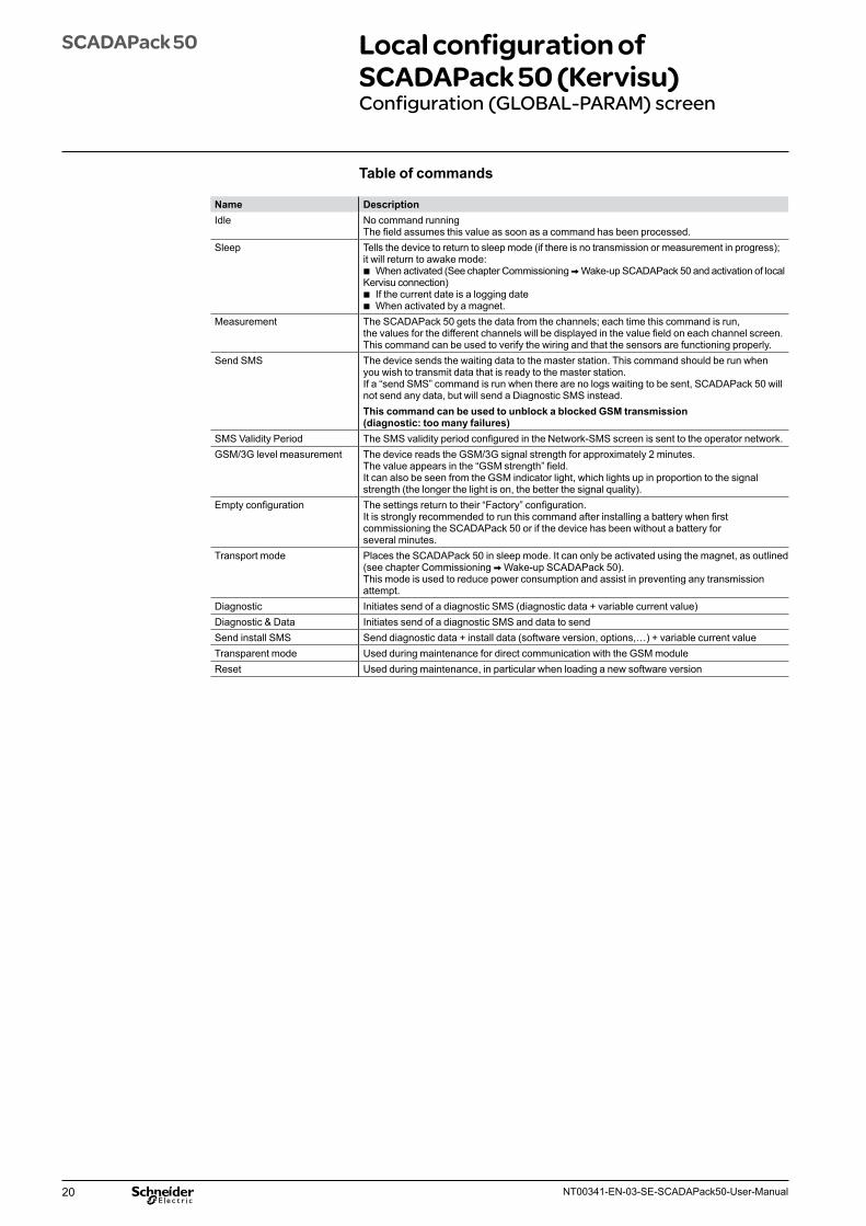
Name DescriptionIdle No command running
The field assumes this value as soon as a command has been processed.Sleep Tells the device to return to sleep mode (if there is no transmission or measurement in progress);
it will return to awake mode: b When activated (See chapter Commissioning V Wake-up SCADAPack 50 and activation of local
Kervisu connection) b If the current date is a logging date b When activated by a magnet.
Measurement The SCADAPack 50 gets the data from the channels; each time this command is run, the values for the different channels will be displayed in the value field on each channel screen. This command can be used to verify the wiring and that the sensors are functioning properly.
Send SMS The device sends the waiting data to the master station. This command should be run whenyou wish to transmit data that is ready to the master station.If a “send SMS” command is run when there are no logs waiting to be sent, SCADAPack 50 will not send any data, but will send a Diagnostic SMS instead.This command can be used to unblock a blocked GSM transmission (diagnostic: too many failures)
SMS Validity Period The SMS validity period configured in the Network-SMS screen is sent to the operator network.GSM/3G level measurement The device reads the GSM/3G signal strength for approximately 2 minutes.
The value appears in the “GSM strength” field.It can also be seen from the GSM indicator light, which lights up in proportion to the signalstrength (the longer the light is on, the better the signal quality).
Empty configuration The settings return to their “Factory” configuration.It is strongly recommended to run this command after installing a battery when first commissioning the SCADAPack 50 or if the device has been without a battery for several minutes.
Transport mode Places the SCADAPack 50 in sleep mode. It can only be activated using the magnet, as outlined (see chapter Commissioning V Wake-up SCADAPack 50).This mode is used to reduce power consumption and assist in preventing any transmission attempt.
Diagnostic Initiates send of a diagnostic SMS (diagnostic data + variable current value)Diagnostic & Data Initiates send of a diagnostic SMS and data to sendSend install SMS Send diagnostic data + install data (software version, options,…) + variable current valueTransparent mode Used during maintenance for direct communication with the GSM moduleReset Used during maintenance, in particular when loading a new software version
Table of commands
21NT00341-EN-03-SE-SCADAPack50-User-Manual
SCADAPack 50 Local configuration of SCADAPack 50 (Kervisu)Channels (V1 to V8) screen
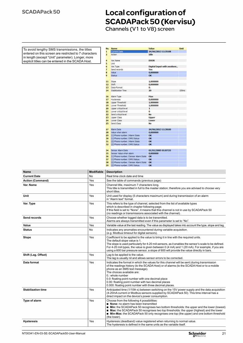
Name Modifiable DescriptionCurrent Date No Real time clock date and timeAction (Command) Yes See the table of commands (previous page)Var. Name Yes Channel title, maximum 7 characters long.
This title is transmitted in full to the master station; therefore you are advised to choose very short titles.
Unit Yes Unit used for display (5 characters maximum) and during transmission of an alarm in “Alarm text” format.
Var. Type Yes This refers to the type of channel, selected from the list of available typeswhich is described in chapter following page.If this field is set to “None”, it means that this channel is not in use by SCADAPack 50 (no readings or transmissions associated with the channel).
Send records Yes Choose whether logged data is to be transmitted.Alarms are always transmitted even if this parameter is set to “No”.
Value Yes Variable value at the last reading. The value as displayed takes into account the type, slope and lag.Status No Indicates any anomalies encountered during variable acquisition.
(e.g. Modbus timeout for digital sensors).Slope Yes Coefficient to be applied to the value to bring it in line with the required units.
The default slope value is 1.The slope is used particularly for 4-20 mA sensors, as it enables the sensor’s scale to be defined.For 4-20 mA types, the value is given between 0 (4 mA) and 1 (20 mA). For example, if you are using a 600 bar pressure sensor, a slope of 600 will provide the value directly in bars.
Shift (Lag. Offset) Yes Lag to be applied to the value.The lag is usually nil and allows sensor errors to be corrected.
Data format Yes Indicates the format in which the values for this channel will be sent (during transmission of the readings history (to the SCADA Host) or of alarms (to the SCADA Host or to a mobile phone as an SMS text message).The choices available are:0.: whole number0.0: floating point number with one decimal place0.00: floating point number with two decimal places0.000: floating point number with three decimal places.
Stabilization time Yes Anticipated time (1/10th s) between switching on the 15V power supply and the data acquisition (4-20mA current or Modbus sensors supplied by SCADAPack 50). This time interval has a direct impact on the device’s power consumption.
Type of alarm Yes Choose from the following 4 possibilities: b None: no alarm has been transmitted b Min: the SCADAPack 50 recognises two bottom thresholds: the upper and the lower (lowest) b Max: the SCADAPack 50 recognises two top thresholds: the upper (highest) and the lower b Min-Max: the SCADAPack 50 only recognises one top (the upper) and one bottom threshold
(the lower).Hysteresis Yes Hysteresis (deadband) value registered when returning to normal value.
The hysteresis is defined in the same units as the variable itself.
To avoid lengthy SMS transmissions, the titles entered on this screen are restricted to 7 characters in length (except “Unit” parameter). Longer, more explicit titles can be entered in the SCADA Host.
22 NT00341-EN-03-SE-SCADAPack50-User-Manual
SCADAPack 50 Local configuration of SCADAPack 50 (Kervisu)Channels (V1 to V8) screen
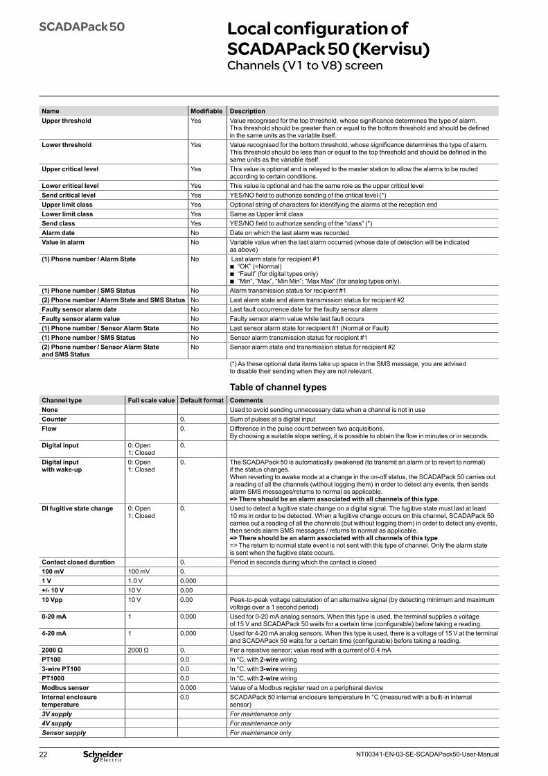
Name Modifiable DescriptionUpper threshold Yes Value recognised for the top threshold, whose significance determines the type of alarm.
This threshold should be greater than or equal to the bottom threshold and should be defined in the same units as the variable itself.
Lower threshold Yes Value recognised for the bottom threshold, whose significance determines the type of alarm. This threshold should be less than or equal to the top threshold and should be defined in the same units as the variable itself.
Upper critical level Yes This value is optional and is relayed to the master station to allow the alarms to be routed according to certain conditions.
Lower critical level Yes This value is optional and has the same role as the upper critical levelSend critical level Yes YES/NO field to authorize sending of the critical level (*)Upper limit class Yes Optional string of characters for identifying the alarms at the reception endLower limit class Yes Same as Upper limit classSend class Yes YES/NO field to authorize sending of the “class” (*)Alarm date No Date on which the last alarm was recordedValue in alarm No Variable value when the last alarm occurred (whose date of detection will be indicated
as above)(1) Phone number / Alarm State No Last alarm state for recipient #1
b “OK” (=Normal) b “Fault” (for digital types only) b “Min”, “Max”, “Min Min”; “Max Max” (for analog types only).
(1) Phone number / SMS Status No Alarm transmission status for recipient #1(2) Phone number / Alarm State and SMS Status No Last alarm state and alarm transmission status for recipient #2Faulty sensor alarm date No Last fault occurrence date for the faulty sensor alarmFaulty sensor alarm value No Faulty sensor alarm value while last fault occurs (1) Phone number / Sensor Alarm State No Last sensor alarm state for recipient #1 (Normal or Fault) (1) Phone number / SMS Status No Sensor alarm transmission status for recipient #1(2) Phone number / Sensor Alarm State and SMS Status
No Sensor alarm state and transmission status for recipient #2
(*) As these optional data items take up space in the SMS message, you are advised to disable their sending when they are not relevant.
Table of channel typesChannel type Full scale value Default format CommentsNone Used to avoid sending unnecessary data when a channel is not in useCounter 0. Sum of pulses at a digital inputFlow 0. Difference in the pulse count between two acquisitions.
By choosing a suitable slope setting, it is possible to obtain the flow in minutes or in seconds.Digital input 0: Open
1: Closed0.
Digital input with wake-up
0: Open 1: Closed
0. The SCADAPack 50 is automatically awakened (to transmit an alarm or to revert to normal) if the status changes.When reverting to awake mode at a change in the on-off status, the SCADAPack 50 carries out a reading of all the channels (without logging them) in order to detect any events, then sends alarm SMS messages/returns to normal as applicable.=> There should be an alarm associated with all channels of this type.
DI fugitive state change 0: Open 1: Closed
0. Used to detect a fugitive state change on a digital signal. The fugitive state must last at least 10 ms in order to be detected. When a fugitive change occurs on this channel, SCADAPack 50 carries out a reading of all the channels (but without logging them) in order to detect any events, then sends alarm SMS messages / returns to normal as applicable.=> There should be an alarm associated with all channels of this type=> The return to normal state event is not sent with this type of channel. Only the alarm state is sent when the fugitive state occurs.
Contact closed duration 0. Period in seconds during which the contact is closed100 mV 100 mV 0. 1 V 1.0 V 0.000+/- 10 V 10 V 0.0010 Vpp 10 V 0.00 Peak-to-peak voltage calculation of an alternative signal (by detecting minimum and maximum
voltage over a 1 second period)0-20 mA 1 0.000 Used for 0-20 mA analog sensors. When this type is used, the terminal supplies a voltage
of 15 V and SCADAPack 50 waits for a certain time (configurable) before taking a reading.4-20 mA 1 0.000 Used for 4-20 mA analog sensors. When this type is used, there is a voltage of 15 V at the terminal
and SCADAPack 50 waits for a certain time (configurable) before taking a reading.2000 Ω 2000 Ω 0. For a resistive sensor; value read with a current of 0.4 mAPT100 0.0 In °C, with 2-wire wiring3-wire PT100 0.0 In °C, with 3-wire wiringPT1000 0.0 In °C, with 2-wire wiringModbus sensor 0.000 Value of a Modbus register read on a peripheral deviceInternal enclosure temperature
0.0 SCADAPack 50 internal enclosure temperature In °C (measured with a built-in internalsensor)
3V supply For maintenance only4V supply For maintenance onlySensor supply For maintenance only
23NT00341-EN-03-SE-SCADAPack50-User-Manual
SCADAPack 50 Local configuration of SCADAPack 50 (Kervisu)Channels (V1 to V8) screen
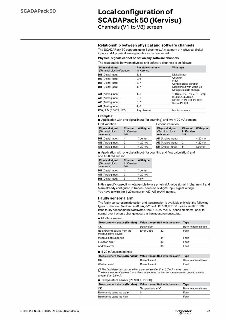
Relationship between physical and software channelsThe SCADAPack 50 supports up to 8 channels. A maximum of 4 physical digital inputs and 4 physical analog inputs can be connected.Physical signals cannot be set on any software channels.The relationship between physical and software channels is as follows:Physical signal (Terminal block reference)
Possible channels in Kervisu
With type
DI1 (Digital Input) 1, 5 Digital InputCounterFlowContact close durationDigital input with wake-upDI fugitive state change
DI2 (Digital Input) 2, 6DI3 (Digital Input) 3, 7 DI4 (Digital Input) 4, 7
AI1 (Analog Input) 1, 5 100 mV, 1 V, ± 10 V, ± 10 Vpp 0-20 mA, 4-20 mA R2000 Ω, PT100, PT1000, 3-wire PT100
AI2 (Analog Input) 2, 6 AI3 (Analog Input) 3, 7 AI4 (Analog Input) 4, 8 RS+, RS- (RS485, JP7) Any channel Modbus sensor
Examples: b Application with one digital input (for counting) and two 4-20 mA sensors
First variation Second variationPhysical signal (Terminal block reference)
Channel in Kervisu 1-8
With type Physical signal (Terminal block reference)
Channel in Kervisu 1-8
With type
DI1 (Digital Input) 1 Counter AI1 (Analog Input) 1 4-20 mAAI2 (Analog Input) 2 4-20 mA AI2 (Analog Input) 2 4-20 mAAI3 (Analog Input) 3 4-20 mA DI1 (Digital Input) 5 Counter
b Application with one digital input (for counting and flow calculation) and one 4-20 mA sensorPhysical signal (Terminal block reference)
Channel in Kervisu 1-8
With type
DI1 (Digital Input) 1 CounterAI2 (Analog Input) 2 4-20 mADI1 (Digital Input) 5 Flow
In this specific case, it is not possible to use physical Analog signal 1 (channels 1 and 5 are already configured in Kervisu because of digital input signal wiring). You have to wire the 4-20 sensor on AI2, AI3 or AI4 instead.
Faulty sensor alarmThe faulty sensor alarm detection and transmission is available only with the following types of channel: Modbus, 4-20 mA, 0-20 mA, PT100, PT100 3 wires and PT1000.If the faulty sensor alarm is activated, the SCADAPack 50 sends an alarm / back to normal event when a change occurs in the measurement status.
b Modbus sensorMeasurement status (Kervisu) Value transmitted with the alarm Type
OK Data value Back to normal stateNo answer received from the Modbus slave device
Error Code 32 Fault
Modbus not supported 34 FaultFunction error 36 FaultAddress error 38 Fault
b 4-20 mA current sensorMeasurement status (Kervisu) * Value transmitted with the alarm Type
OK Current in mA Back to normal stateWeak current Current in mA Fault
(*) The fault detection occurs when a current smaller than 3.7 mA is measured. The back to normal state is transmitted as soon as the current measurement goes to a value greater than 3.8 mA.
b Temperature sensor (PT100, PT1000)Measurement status (Kervisu) Value transmitted with the alarm Type
OK Temperature in °C Back to normal stateResistance value too weak 0 FaultResistance value too high 1 Fault
24 NT00341-EN-03-SE-SCADAPack50-User-Manual
SCADAPack 50 Local configuration of SCADAPack 50 (Kervisu)Channels (V1 to V8) screen
Operation of alarmsThe SCADAPack 50 accommodates:
b 3 types of alarm: Min, Max and Min-Max b 2 thresholds: Top and Bottom
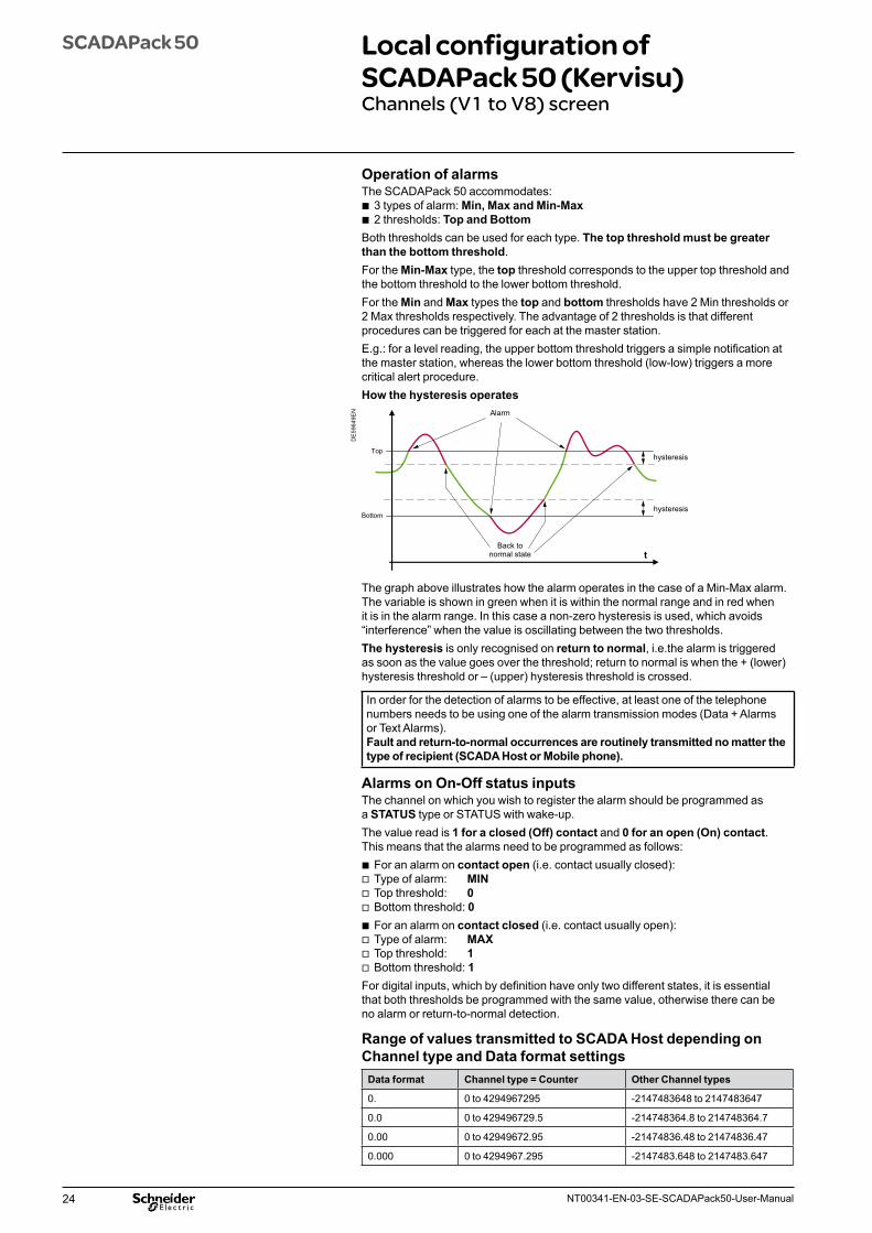
Both thresholds can be used for each type. The top threshold must be greater than the bottom threshold.For the Min-Max type, the top threshold corresponds to the upper top threshold and the bottom threshold to the lower bottom threshold.For the Min and Max types the top and bottom thresholds have 2 Min thresholds or 2 Max thresholds respectively. The advantage of 2 thresholds is that different procedures can be triggered for each at the master station.E.g.: for a level reading, the upper bottom threshold triggers a simple notification at the master station, whereas the lower bottom threshold (low-low) triggers a more critical alert procedure.How the hysteresis operates
DE
5964
9EN
Top
Bottom
hysteresis
hysteresis
t
Alarm
Back to normal state
The graph above illustrates how the alarm operates in the case of a Min-Max alarm. The variable is shown in green when it is within the normal range and in red when it is in the alarm range. In this case a non-zero hysteresis is used, which avoids “interference” when the value is oscillating between the two thresholds.The hysteresis is only recognised on return to normal, i.e.the alarm is triggered as soon as the value goes over the threshold; return to normal is when the + (lower) hysteresis threshold or – (upper) hysteresis threshold is crossed.
In order for the detection of alarms to be effective, at least one of the telephone numbers needs to be using one of the alarm transmission modes (Data + Alarms or Text Alarms).Fault and return-to-normal occurrences are routinely transmitted no matter the type of recipient (SCADA Host or Mobile phone).
Alarms on On-Off status inputsThe channel on which you wish to register the alarm should be programmed as a STATUS type or STATUS with wake-up.The value read is 1 for a closed (Off) contact and 0 for an open (On) contact. This means that the alarms need to be programmed as follows:
b For an alarm on contact open (i.e. contact usually closed): v Type of alarm: MIN v Top threshold: 0 v Bottom threshold: 0 b For an alarm on contact closed (i.e. contact usually open): v Type of alarm: MAX v Top threshold: 1 v Bottom threshold: 1
For digital inputs, which by definition have only two different states, it is essential that both thresholds be programmed with the same value, otherwise there can be no alarm or return-to-normal detection.
Range of values transmitted to SCADA Host depending on Channel type and Data format settings
Data format Channel type = Counter Other Channel types
0. 0 to 4294967295 -2147483648 to 2147483647
0.0 0 to 429496729.5 -214748364.8 to 214748364.7
0.00 0 to 42949672.95 -21474836.48 to 21474836.47
0.000 0 to 4294967.295 -2147483.648 to 2147483.647
25NT00341-EN-03-SE-SCADAPack50-User-Manual
SCADAPack 50 Local configuration of SCADAPack 50 (Kervisu)Counters screenSystem screen
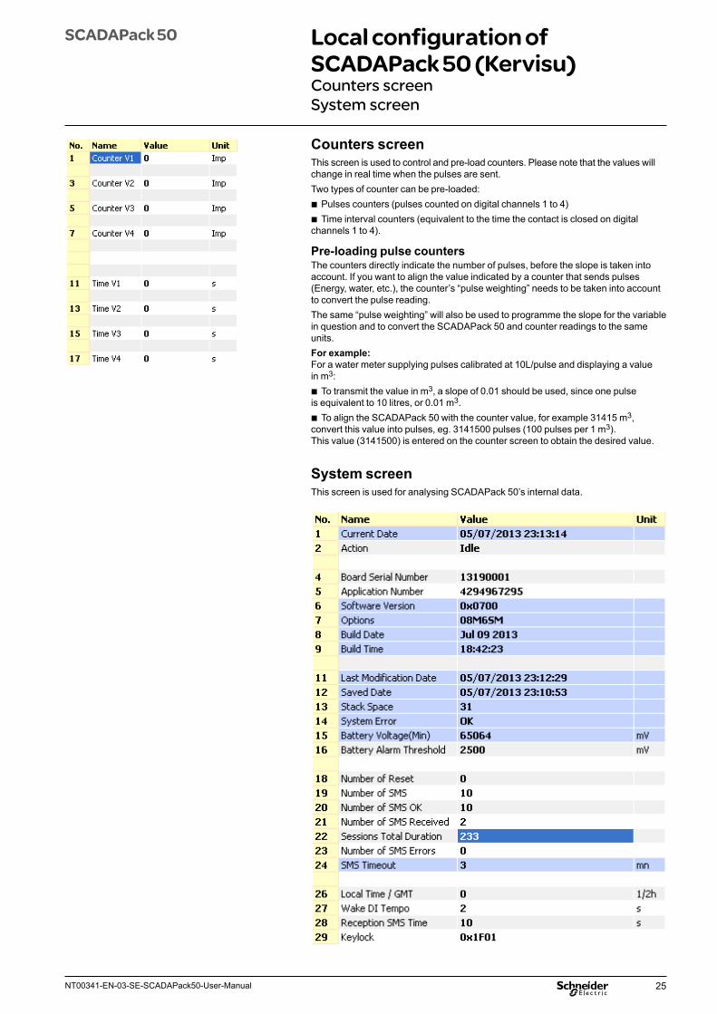
Counters screenThis screen is used to control and pre-load counters. Please note that the values will change in real time when the pulses are sent. Two types of counter can be pre-loaded:
b Pulses counters (pulses counted on digital channels 1 to 4) b Time interval counters (equivalent to the time the contact is closed on digital
channels 1 to 4).
Pre-loading pulse countersThe counters directly indicate the number of pulses, before the slope is taken into account. If you want to align the value indicated by a counter that sends pulses (Energy, water, etc.), the counter’s “pulse weighting” needs to be taken into account to convert the pulse reading. The same “pulse weighting” will also be used to programme the slope for the variable in question and to convert the SCADAPack 50 and counter readings to the same units.For example:For a water meter supplying pulses calibrated at 10L/pulse and displaying a value in m3:
b To transmit the value in m3, a slope of 0.01 should be used, since one pulse is equivalent to 10 litres, or 0.01 m3.
b To align the SCADAPack 50 with the counter value, for example 31415 m3, convert this value into pulses, eg. 3141500 pulses (100 pulses per 1 m3). This value (3141500) is entered on the counter screen to obtain the desired value.
System screenThis screen is used for analysing SCADAPack 50’s internal data.
26 NT00341-EN-03-SE-SCADAPack50-User-Manual
SCADAPack 50 Local configuration of SCADAPack 50 (Kervisu)Network-SMS screenSystem message table
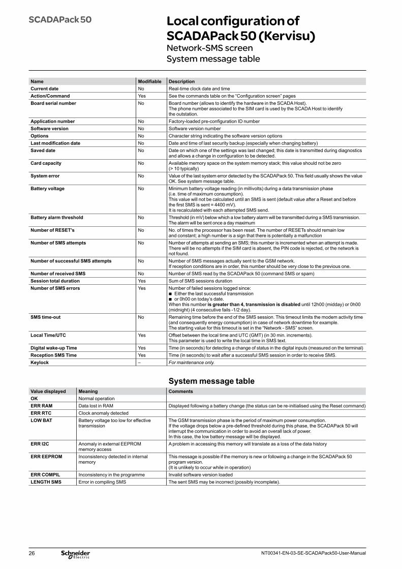
Name Modifiable DescriptionCurrent date No Real-time clock date and time Action/Command Yes See the commands table on the “Configuration screen” pages Board serial number No Board number (allows to identify the hardware in the SCADA Host).
The phone number associated to the SIM card is used by the SCADA Host to identify the outstation.
Application number No Factory-loaded pre-configuration ID numberSoftware version No Software version numberOptions No Character string indicating the software version optionsLast modification date No Date and time of last security backup (especially when changing battery)Saved date No Date on which one of the settings was last changed; this date is transmitted during diagnostics
and allows a change in configuration to be detected.Card capacity No Available memory space on the system memory stack; this value should not be zero
(> 10 typically)System error No Value of the last system error detected by the SCADAPack 50. This field usually shows the value
OK. See system message table.Battery voltage No Minimum battery voltage reading (in millivolts) during a data transmission phase
(i.e. time of maximum consumption).This value will not be calculated until an SMS is sent (default value after a Reset and before the first SMS is sent = 4400 mV).It is recalculated with each attempted SMS send.
Battery alarm threshold No Threshold (in mV) below which a low battery alarm will be transmitted during a SMS transmission.The alarm will be sent once a day maximum
Number of RESET’s No No. of times the processor has been reset. The number of RESETs should remain low and constant; a high number is a sign that there is potentially a malfunction
Number of SMS attempts No Number of attempts at sending an SMS; this number is incremented when an attempt is made. There will be no attempts if the SIM card is absent, the PIN code is rejected, or the network is not found.
Number of successful SMS attempts No Number of SMS messages actually sent to the GSM network.If reception conditions are in order, this number should be very close to the previous one.
Number of received SMS No Number of SMS read by the SCADAPack 50 (command SMS or spam)Session total duration Yes Sum of SMS sessions durationNumber of SMS errors Yes Number of failed sessions logged since:
b Either the last successful transmission b or 0h00 on today’s date.
When this number is greater than 4, transmission is disabled until 12h00 (midday) or 0h00 (midnight) (4 consecutive fails -1/2 day).
SMS time-out No Remaining time before the end of the SMS session. This timeout limits the modem activity time (and consequently energy consumption) in case of network downtime for example.The starting value for this timeout is set in the “Network - SMS” screen.
Local Time/UTC Yes Offset between the local time and UTC (GMT) (in 30 min. increments).This parameter is used to write the local time in SMS text.
Digital wake-up Time Yes Time (in seconds) for detecting a change of status in the digital inputs (measured on the terminal)Reception SMS Time Yes Time (in seconds) to wait after a successful SMS session in order to receive SMS.Keylock – For maintenance only.
System message tableValue displayed Meaning CommentsOK Normal operationERR RAM Data lost in RAM Displayed following a battery change (the status can be re-initialised using the Reset command)ERR RTC Clock anomaly detectedLOW BAT Battery voltage too low for effective
transmissionThe GSM transmission phase is the period of maximum power consumption. If the voltage drops below a pre-defined threshold during this phase, the SCADAPack 50 will interrupt the communication in order to avoid an overall lack of power. In this case, the low battery message will be displayed.
ERR I2C Anomaly in external EEPROMmemory access
A problem in accessing this memory will translate as a loss of the data history
ERR EEPROM Inconsistency detected in internal memory
This message is possible if the memory is new or following a change in the SCADAPack 50 program version.(It is unlikely to occur while in operation)
ERR COMPIL Inconsistency in the programme Invalid software version loadedLENGTH SMS Error in compiling SMS The sent SMS may be incorrect (possibly incomplete).
27NT00341-EN-03-SE-SCADAPack50-User-Manual
SCADAPack 50 Local configuration of SCADAPack 50 (Kervisu)Network - SMS screen
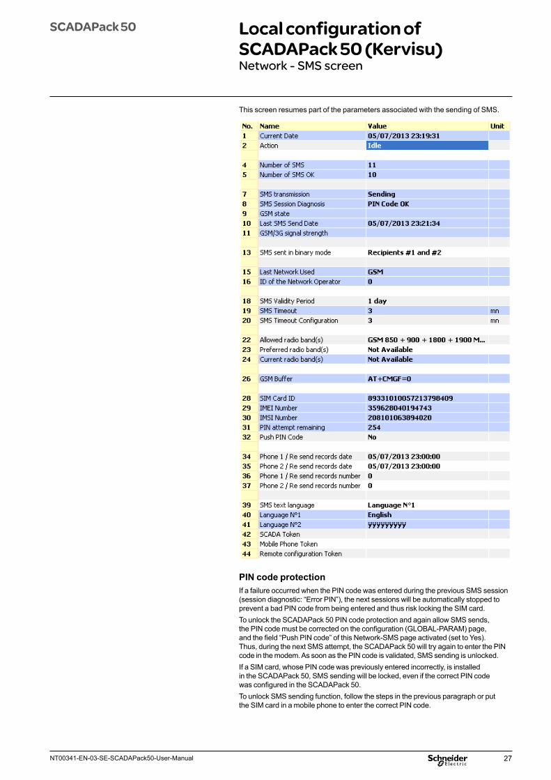
PIN code protectionIf a failure occurred when the PIN code was entered during the previous SMS session (session diagnostic: “Error PIN”), the next sessions will be automatically stopped to prevent a bad PIN code from being entered and thus risk locking the SIM card.To unlock the SCADAPack 50 PIN code protection and again allow SMS sends, the PIN code must be corrected on the configuration (GLOBAL-PARAM) page, and the field “Push PIN code” of this Network-SMS page activated (set to Yes). Thus, during the next SMS attempt, the SCADAPack 50 will try again to enter the PIN code in the modem. As soon as the PIN code is validated, SMS sending is unlocked.If a SIM card, whose PIN code was previously entered incorrectly, is installed in the SCADAPack 50, SMS sending will be locked, even if the correct PIN code was configured in the SCADAPack 50.To unlock SMS sending function, follow the steps in the previous paragraph or put the SIM card in a mobile phone to enter the correct PIN code.
This screen resumes part of the parameters associated with the sending of SMS.
28 NT00341-EN-03-SE-SCADAPack50-User-Manual
SCADAPack 50 Local configuration of SCADAPack 50 (Kervisu)Network - SMS screen
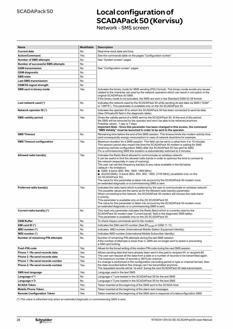
Name Modifiable DescriptionCurrent date No Real-time clock date and timeAction/Command Yes See the commands table on the pages “Configuration screen”Number of SMS attempts No See “System screen” pagesNumber of successful SMS attempts NoGSM transmission No See “Configuration screen” pagesGSM diagnostic NoSMS state NoLast SMS transmission NoGSM/3G signal strength NoSMS sent in binary mode Yes Activates the binary mode for SMS sending (PDU format). This binary mode avoids any issues
related to the character set used by the network operators which can result in corruption in the original SCADAPack 50 SMS.If the binary mode is not activated, the SMS are sent in the Standard GSM 03.38 format.
Last network used (*) No Indicates the network used by the SCADAPack 50 while sending its last data via SMS (“GSM” or “UMTS”). This parameter is available only on the 3G SCADAPack 50.
Network operator ID (*) No Indicates the operator ID to which the SCADAPack 50 has been connected to send its data(See OPeratorID field in the diagnostic table).
SMS validity period Yes Gives the validity period of a SMS sent by the SCADAPack 50. At the end of this period, the SMS will be removed by the operator and won’t be able to be retrieved anymore.Possible values : 1 day or 7 daysImportant Note : Once this parameter has been changed in this screen, the command “SMS Validity” must be launched in order to be sent to the operator.
SMS Timeout No Remaining time before the end of the SMS session. This timeout limits the modem activity time (and consequently energy consumption) in case of network downtime for example.
SMS Timeout configuration Yes Maximum duration for a SMS session. This field can be set to a value from 3 to 15 minutes.This session period also impact the time the SCADAPack 50 modem is waiting for SMS receiving (remote configuration SMS) after the SCADAPack 50 has sent its SMS.For a commissioning SMS this duration is automatically switched to 5 minutes.
Allowed radio band(s) Yes Indicates the Radio Band allowed to communicate on wireless network. It can be useful to limit the allowed radio bands in order to optimize the time to connect to the network (especially in case of roaming).The user can set this frequency band(s) to any value available in the list below (default = No limitation):
b GSM: 4-band (850, 900, 1800, 1900 MHz) b 3G(WCDMA): 5-band (800, 850, 900, 1900, 2100 MHz) (available only on the
3G SCADAPack 50).The value for this parameter is taken into account by the SCADAPack 50 modem once an extended diagnostic or a commissioning SMS is sent.
Preferred radio band(s) Yes Indicates the radio band which is preferred by the user to communicate on wireless network. The possible values are the same as for the Allowed radio band(s) parameter.When connecting to the network, the SCADAPack 50 modem will choose this radio band in priority.This parameter is available only on the 2G SCADAPack 50.The value for this parameter is taken into account by the SCADAPack 50 modem once an extended diagnostic or a commissioning SMS is sent.
Current radio band(s) (*) No This read only parameter indicates the Radio Band which is currently used by the SCADAPack 50 modem (see “Current bands” field in the diagnostic SMS table).This parameter is available only on the 2G SCADAPack 50.
GSM Buffer No To check Hayes commands sent to the modemSIM card ID (*) No Indicates the SIM card ID number (See EFICCID in GSM 11.11)IMEI number (*) No Indicates IMEI number (International Mobile Station Equipment Identity)IMSI number (*) No Indicates IMSI number (International Mobile Subscriber Identity)Number of remaining PIN attempts No Number of remaining PIN attempts during the last SMS session.
If the number of attempts is lower than 3, SMS are no longer sent to assist in preventing a SIM card locking.
Push PIN code Yes Allows for the forced writing of the modem PIN code during the next SMS session.Phone 1 / Re send records date Yes Allows sending data that have already been sent in the past to recipient #1 or recipient #2.
The user can request all the data from a date or a number of records to be transmitted again.The maximum number of records is 3875 per channel.If a change is performed in the configuration (recording period or type or channel format), then the data recorded before this change can’t be transmitted anymore.The requested records will be “re-sent” during the next SCADAPack 50 data transmission.
Phone 2 / Re send records date YesPhone 1 / Re send records number YesPhone 2 / Re send records number Yes
SMS text language Yes Language used in the text SMSLanguage n°1 No Language n°1 pre-loaded in the SCADAPack 50 for the text SMSLanguage n°2 No Language n°2 pre-loaded in the SCADAPack 50 for the text SMSSCADA Token Yes Token inserted at the beginning of the SMS sent to the SCADA HostMobile Phone Token Yes Token inserted at the beginning of the alarm text messagesRemote Configuration Token Yes Token inserted at the beginning of the SMS sent in response of a teleconfiguration SMS
(*) This value is refreshed only when an extended diagnostic or commissioning SMS is sent.
29NT00341-EN-03-SE-SCADAPack50-User-Manual
SCADAPack 50 Local configuration of SCADAPack 50 (Kervisu)MODBUS-PARAM settings screen
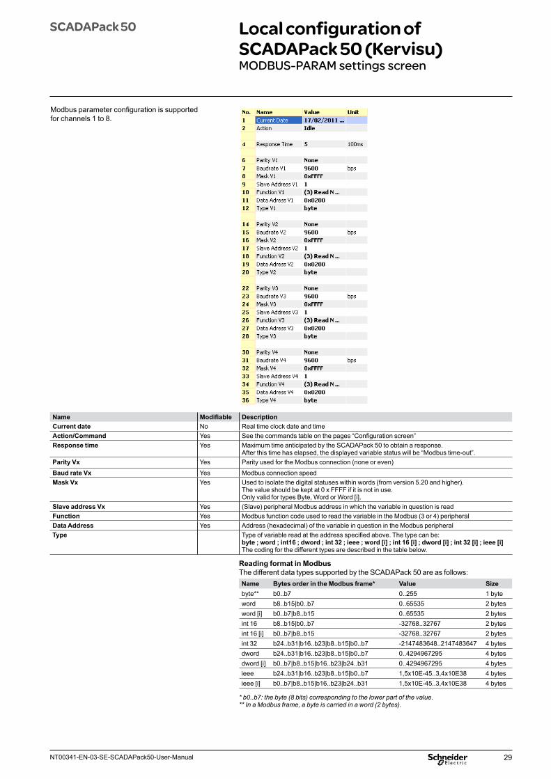
Name Modifiable DescriptionCurrent date No Real time clock date and timeAction/Command Yes See the commands table on the pages “Configuration screen”Response time Yes Maximum time anticipated by the SCADAPack 50 to obtain a response.
After this time has elapsed, the displayed variable status will be “Modbus time-out”.Parity Vx Yes Parity used for the Modbus connection (none or even)
Baud rate Vx Yes Modbus connection speedMask Vx Yes Used to isolate the digital statuses within words (from version 5.20 and higher).
The value should be kept at 0 x FFFF if it is not in use.Only valid for types Byte, Word or Word [i].
Slave address Vx Yes (Slave) peripheral Modbus address in which the variable in question is readFunction Yes Modbus function code used to read the variable in the Modbus (3 or 4) peripheralData Address Yes Address (hexadecimal) of the variable in question in the Modbus peripheralType Type of variable read at the address specified above. The type can be:
byte ; word ; int16 ; dword ; int 32 ; ieee ; word [i] ; int 16 [i] ; dword [i] ; int 32 [i] ; ieee [i]The coding for the different types are described in the table below.
Reading format in ModbusThe different data types supported by the SCADAPack 50 are as follows:Name Bytes order in the Modbus frame* Value Sizebyte** b0..b7 0..255 1 byteword b8..b15|b0..b7 0..65535 2 bytesword [i] b0..b7|b8..b15 0..65535 2 bytesint 16 b8..b15|b0..b7 -32768..32767 2 bytesint 16 [i] b0..b7|b8..b15 -32768..32767 2 bytesint 32 b24..b31|b16..b23|b8..b15|b0..b7 -2147483648..2147483647 4 bytesdword b24..b31|b16..b23|b8..b15|b0..b7 0..4294967295 4 bytesdword [i] b0..b7|b8..b15|b16..b23|b24..b31 0..4294967295 4 bytesieee b24..b31|b16..b23|b8..b15|b0..b7 1,5x10E-45..3,4x10E38 4 bytesieee [i] b0..b7|b8..b15|b16..b23|b24..b31 1,5x10E-45..3,4x10E38 4 bytes
* b0..b7: the byte (8 bits) corresponding to the lower part of the value. ** In a Modbus frame, a byte is carried in a word (2 bytes).
Modbus parameter configuration is supported for channels 1 to 8.
30 NT00341-EN-03-SE-SCADAPack50-User-Manual
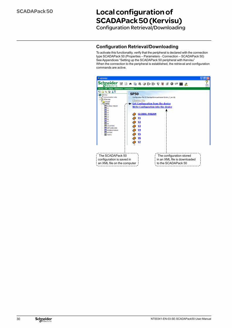
Configuration Retrieval/DownloadingTo activate this functionality, verify that the peripheral is declared with the connection type SCADAPack 50 (Properties – Parameters - Connection – SCADAPack 50) See Appendices “Setting up the SCADAPack 50 peripheral with Kervisu”When the connection to the peripheral is established, the retrieval and configuration commands are active.
SCADAPack 50 Local configuration of SCADAPack 50 (Kervisu)Configuration Retrieval/Downloading
The SCADAPack 50 configuration is saved in an XML file on the computer
The configuration stored in an XML file is downloaded to the SCADAPack 50
31NT00341-EN-03-SE-SCADAPack50-User-Manual
The network connection is good, but the SCADAPack 50 does not send anything when the “send SMS” command is run.
Check that at least one of the receiving numbers is registered in DATA mode along with itstelephone number, and that the PIN code entered is correct. If there is no log waiting to be sent, the SCADAPack 50 will send a diagnostic SMS.
I would like to adjust my counter indexes to the reading on the counter itself.
Simply go to the “counters” screen and enter the required value. This value is in pulses; in somecases, you will first need to convert the value read on the counter into the number of pulses.For example:
b A water meter displays 450,320 litres b The pulse value is 0.1 litre/pulse (indicated on the counter) b The counter’s index in pulses is 450,320 L x 10 pulses/L, or 4,503,200 pulses
The latter value is entered into the SCADAPack 50.The value can be set to scale (in litres) in the appropriate channel in the SCADAPack 50 (slope field = 0.1). The SCADA Host will therefore receive the values for this counter directly in litres (i.e. the SCADA Host will not need to convert the value).
After connecting a 4-20mA sensor, the value on the reading is still very low.
Proceed carefully, as 4-20 mA sensors have a different wiring procedure: b The sensor’s + terminal should be connected to the 15V power supply’s + terminal. b The sensor’s – terminal should be connected to the “signal” input of the selected channel
on the analog input terminal block (under no circumstances should it be connected to the 0V reference).
b Power for the 4-20 mA loop is supplied by SCADAPack 50 during readings only, which are on a timeout of approximately one second. The sensor should therefore provide a stable signal no later than 1 second after connecting to the power; this setting is usually provided in the sensor manufacturer’s documentation. The SCADAPack 50 wait time can be increased by adjusting the setting «Stabilization time” in the corresponding Kervisu Channel screen (given in 1/10s of a second).
What types of pulse emitter can be connected? The SCADAPack 50 is adapted for many pulse emitters, especially reed-switch systems, which are found in many gas or water meters. In this instance, the polarity does not matter. Some electronic counters have a polarised input which therefore needs to be connected correctly. (The + to the input and the – to the shared GND).A tip for checking the wiring: with a multimeter (high impedance), you should get a reading of around 3 volts between the input and the GND, except when a pulse is passing through, at which time the voltage falls below one volt.
Logged data has been received by the SCADA Host, but has been inserted in future dates. Why is this?
There are 3 possible causes: b The SCADAPack 50 is not set to the correct date and time (or these were not correct at the time
they were set), in which case, you should set the correct UTC time on the “Configuration” screen (Kervisu).
b “Extra” logs have been included, via the “Logging” command b The battery has been removed for a period of time and the logging interval has not been
re-programmed: in this case, you are advised to change the logging interval to a new value, then to enter the value required. The SCADAPack 50 will then automatically re-calculate the time intervals for each of its channels.
Even though the USB-IrDA interface has been correctly installed and the correct serial port has been assigned in Kervisu, why am I still unable to establish a local connection between my Kervisu and the SCADAPack 50?
In Kervisu, check that the address is set to 1 in the SCADAPack 50 peripheral properties. (By default it is set to 10.).
SCADAPack 50 Frequently asked questions
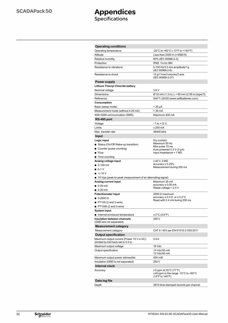
32 NT00341-EN-03-SE-SCADAPack50-User-Manual
SCADAPack 50 AppendicesSpecifications
Operating conditionsOperating temperature -25°C to +60°C (-13°F to +140°F)Altitude Less than 2000 m (≈ 6560 ft)Relative humidity 90% (IEC 60068-2-3)Protection IP68: 1m for 96hResistance to vibrations 5-150 Hz/3.5 mm amplitude/1 g
(IEC 60068-2-6)Resistance to shock 15 g/11ms/3 shocks/3 axis
(IEC 60068-2-27) Power supplyLithium Thionyl Chloride batteryNominal voltage 3.6 VDimensions Ø 33 mm (1.3 in), L = 60 mm (2.36 in) (type D)Reference SAFT LSH20 (www.saftbatteries.com)ConsumptionBasic (sleep mode) < 30 μAMeasurement mode (without 4-20 mA) < 30 mAWith GSM communication (SMS) Maximum 400 mA RS-485 portVoltage - 7 to +12 V,Limits ± 250 mAMax. transfer rate 38400 bit/s InputLogic input Dry contact
Maximum 50 Hz Mini pulse 10 msAuto powered 3.3 V (3 μA)Input impedance > 1 MΩ
b Status (On/Off Wake-up transition) b Counter (pulse counting) b Flow b Time counting
Analog voltage input ± 40 V, 2 MΩ accuracy ± 0.25%Measurement during 200 ms
b 0-100 mV b 0-1 V b +/-10 V b 10 Vpp (peak-to-peak measurement of an alternating signal)
Analog current input Maximum 35 mAaccuracy ± 0,05 mAWaste voltage < 2.5 V
b 0-20 mA b 4-20 mA
Potentiometer input 2000 Ω maximumaccuracy ± 0.5 Ω or ± 0.2°C Read with 0.4 mA during 200 ms
b 0-2000 Ω b PT100 (2 and 3-wire) b PT1000 (2 and 3-wire)
System input b Internal enclosure temperature ± 2°C (3.6°F)
Insulation between channels (GND are not separated)
250 V
Measurement category Measurement category CAT 0 / 40V per EN 61010-2-030:2011 Output specificationMaximum output current (Power 15 V in SC) (limited by fold back set to 0.5 s)
0.6 A
Maximum output voltage 16 VdcOutput specification 14 Vdc/35 mA
12 Vdc/40 mAMaximum output power admissible 400 mWInsulation (GND is not separated) 250 V Internal clockAccuracy ± 5 ppm at 25°C (77°F)
± 40 ppm in the range -10°C to +60°C (14°F to 140°F)
Data log fileDepth 3875 time-stamped records per channel
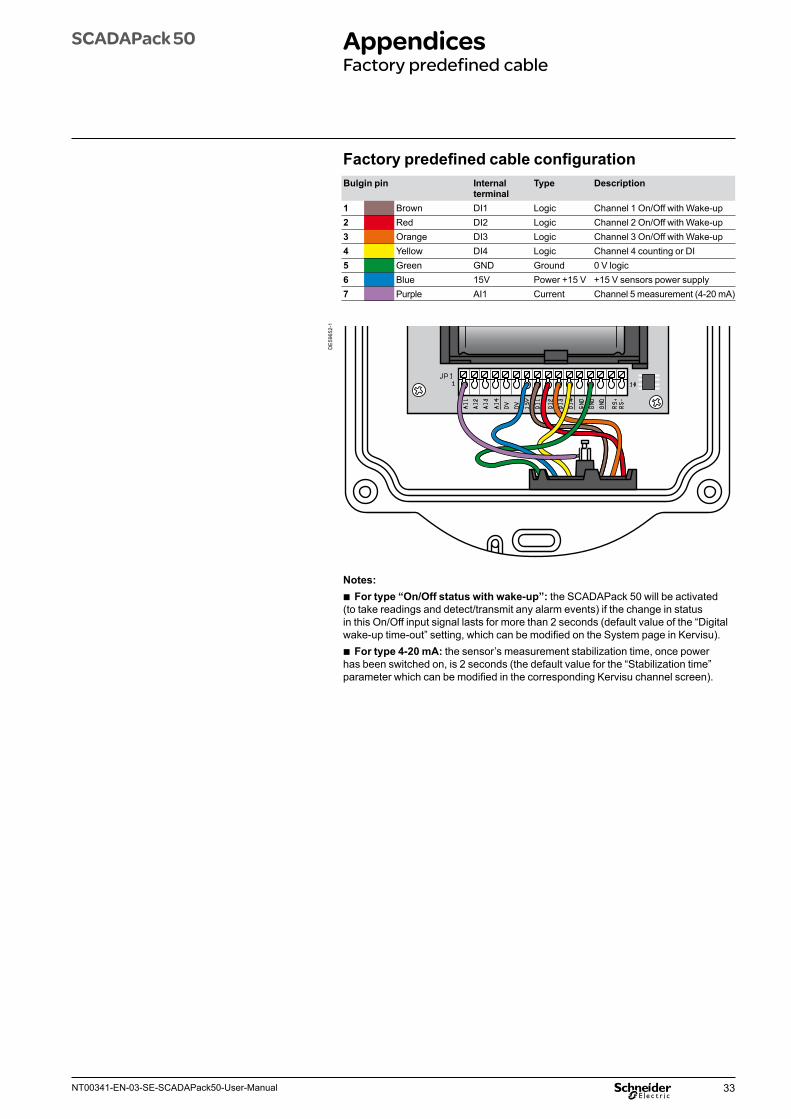
33NT00341-EN-03-SE-SCADAPack50-User-Manual
SCADAPack 50 AppendicesFactory predefined cable
Factory predefined cable configurationBulgin pin Internal
terminalType Description
1 Brown DI1 Logic Channel 1 On/Off with Wake-up2 Red DI2 Logic Channel 2 On/Off with Wake-up3 Orange DI3 Logic Channel 3 On/Off with Wake-up4 Yellow DI4 Logic Channel 4 counting or DI5 Green GND Ground 0 V logic6 Blue 15V Power +15 V +15 V sensors power supply7 Purple AI1 Current Channel 5 measurement (4-20 mA)
DE
5965
2-1
Notes: b For type “On/Off status with wake-up”: the SCADAPack 50 will be activated
(to take readings and detect/transmit any alarm events) if the change in status in this On/Off input signal lasts for more than 2 seconds (default value of the “Digital wake-up time-out” setting, which can be modified on the System page in Kervisu).
b For type 4-20 mA: the sensor’s measurement stabilization time, once power has been switched on, is 2 seconds (the default value for the “Stabilization time” parameter which can be modified in the corresponding Kervisu channel screen).
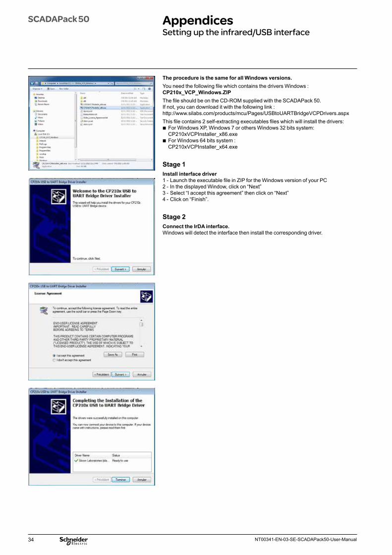
34 NT00341-EN-03-SE-SCADAPack50-User-Manual
SCADAPack 50 AppendicesSetting up the infrared/USB interface
The procedure is the same for all Windows versions.You need the following file which contains the drivers Windows : CP210x_VCP_Windows.ZIP The file should be on the CD-ROM supplied with the SCADAPack 50. If not, you can download it with the following link : http://www.silabs.com/products/mcu/Pages/USBtoUARTBridgeVCPDrivers.aspxThis file contains 2 self-extracting executables files which will install the drivers:
b For Windows XP, Windows 7 or others Windows 32 bits system: CP210xVCPInstaller_x86.exe
b For Windows 64 bits system : CP210xVCPInstaller_x64.exe
Stage 1Install interface driver1 - Launch the executable file in ZIP for the Windows version of your PC2 - In the displayed Window, click on “Next”3 - Select “I accept this agreement” then click on “Next”4 - Click on “Finish”.
Stage 2Connect the IrDA interface.Windows will detect the interface then install the corresponding driver.

35NT00341-EN-03-SE-SCADAPack50-User-Manual
SCADAPack 50 AppendicesSetting up the infrared/USB interface
Checking which COM port is being usedOnce the Driver has been installed, Windows will create a new COM port, which will be the first available port before the driver was installed: for example if COM1, COM2 and COM3 are already allocated on the PC, the location used by the infrared port will be COM4.To find out which COM port is being used, you will need to look in the driver manager:
b Click on Start b Right click on the computer or the workstation
(under Windows XP) b Go to the properties section, hardware tab
(under Windows XP) b Choose the Device manager section b Select the communication ports from the list b The USB-IrDA interface will be on the COM port
marked “CP2101 USB to UART bridge controller”; in this example, this is COM4.
If the COM port which your computer has allocated to the USB – IrDA interface is not convenient (e.g. if it is COM3 and this is usually used by your PC’s internal modem), the port allocation can be changed by performing the following operations:
On the “Device manager” screen: b Point the port “CP2101 USB to UART…”. b Right click then select “Properties”.
The window “CP2101 USB…properties” will be displayed: b Choose the “Port Settings” tab b Then click on “Advanced”
In the advanced settings window, select the port number you require
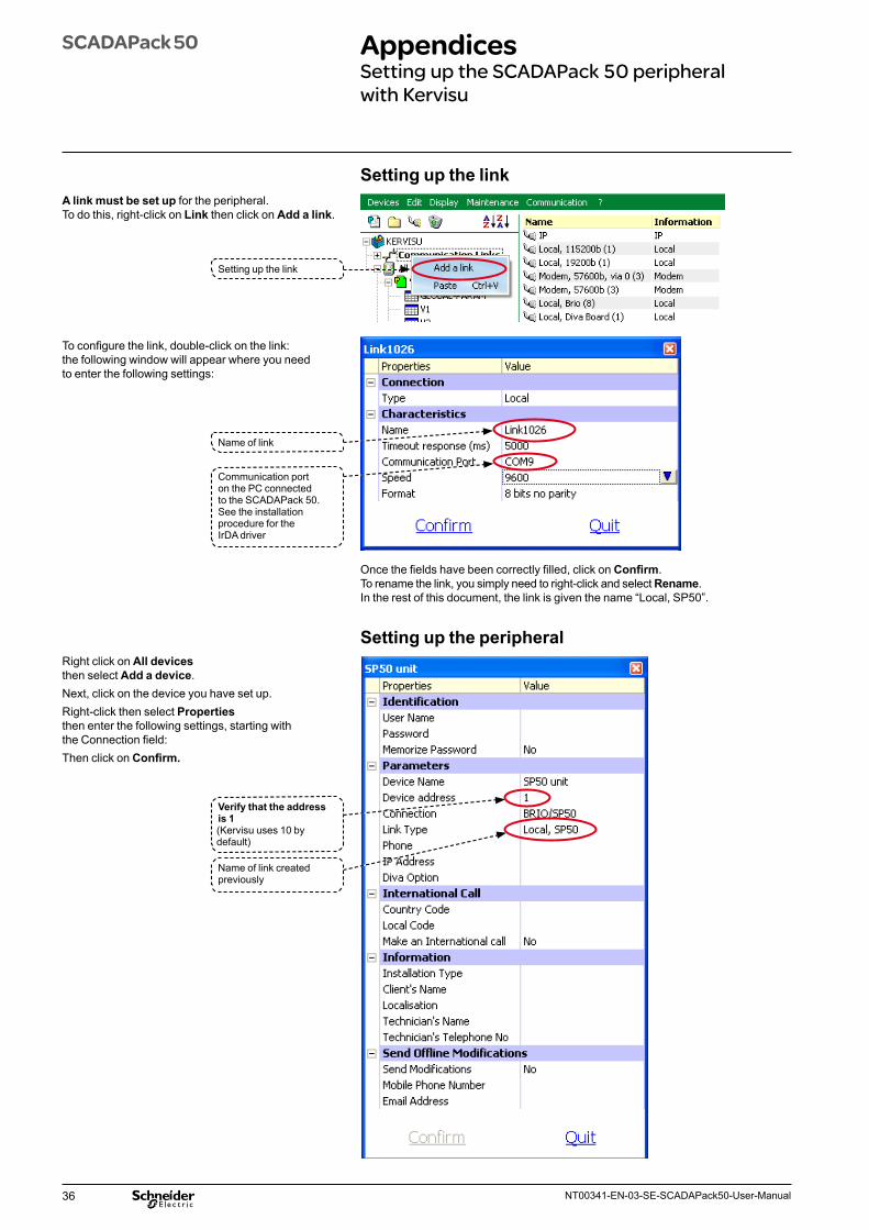
36 NT00341-EN-03-SE-SCADAPack50-User-Manual
SCADAPack 50 AppendicesSetting up the SCADAPack 50 peripheral with Kervisu
Setting up the link
Setting up the link
Name of link
Communication port on the PC connected to the SCADAPack 50. See the installation procedure for the IrDA driver
Once the fields have been correctly filled, click on Confirm.To rename the link, you simply need to right-click and select Rename.In the rest of this document, the link is given the name “Local, SP50”.
Setting up the peripheral
Verify that the address is 1(Kervisu uses 10 by default)
Name of link created previously
A link must be set up for the peripheral. To do this, right-click on Link then click on Add a link.
To configure the link, double-click on the link: the following window will appear where you need to enter the following settings:
Right click on All devices then select Add a device. Next, click on the device you have set up. Right-click then select Properties then enter the following settings, starting with the Connection field:Then click on Confirm.
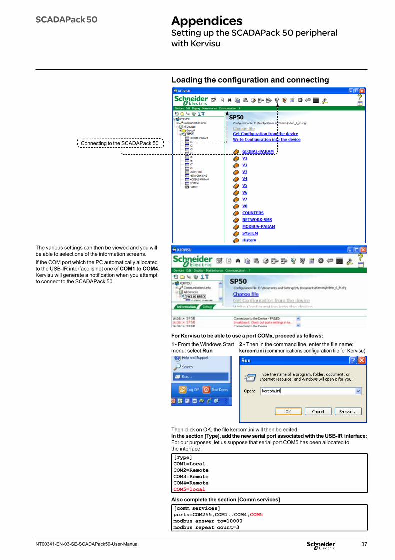
37NT00341-EN-03-SE-SCADAPack50-User-Manual
SCADAPack 50 AppendicesSetting up the SCADAPack 50 peripheral with Kervisu
Loading the configuration and connecting
Connecting to the SCADAPack 50
The various settings can then be viewed and you will be able to select one of the information screens.If the COM port which the PC automatically allocated to the USB-IR interface is not one of COM1 to COM4, Kervisu will generate a notification when you attempt to connect to the SCADAPack 50.
For Kervisu to be able to use a port COMx, proceed as follows:1 - From the Windows Start menu: select Run
2 - Then in the command line, enter the file name: kercom.ini (communications configuration file for Kervisu).
Then click on OK, the file kercom.ini will then be edited.In the section [Type], add the new serial port associated with the USB-IR interface:For our purposes, let us suppose that serial port COM5 has been allocated to the interface:[Type]COM1=LocalCOM2=RemoteCOM3=RemoteCOM4=RemoteCOM5=local
Also complete the section [Comm services][comm services]ports=COM255,COM1..COM4,COM5modbus answer to=10000modbus repeat count=3
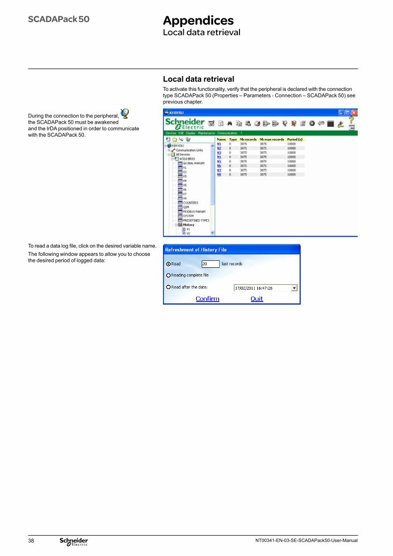
38 NT00341-EN-03-SE-SCADAPack50-User-Manual
SCADAPack 50 AppendicesLocal data retrieval
Local data retrievalTo activate this functionality, verify that the peripheral is declared with the connection type SCADAPack 50 (Properties – Parameters - Connection – SCADAPack 50) see previous chapter.
During the connection to the peripheral, the SCADAPack 50 must be awakened and the IrDA positioned in order to communicate with the SCADAPack 50.
To read a data log file, click on the desired variable name. The following window appears to allow you to choose the desired period of logged data:
39NT00341-EN-03-SE-SCADAPack50-User-Manual
SCADAPack 50 AppendicesTips for opening your GSM account
Tips for opening your GSM accountThe GSM account for the SCADAPack 50It is not necessary to open a voice & data account: a machine-to-machine account will suffice, which will not include a voice function.If there is a risk of PIN code theft, you should use a different PIN code from the default code given by the network operator (usually 0000).If this is not likely, the energy consumed by GSM transmissions can be reduced by suppressing the PIN code request (this reduces the time required for transmission).With some network operators, you will need to request your SIM card to be activated before it is first used by the SCADAPack 50. This is done simply by telephoning the network operator. The purpose of activation is to:
b Enable you to be connected to the network b Set up regular billing on your account.
SCADA Host GSM/3G account subscriptionThe same type of account is required for the SCADA Host station, and can be supplied by a different network operator if required. If you are operating a large number of devices giving rise to more than 10,000 MSMS messages per year, you are strongly advised to request a terrestrial connection from your chosen network operator: this will improve reception security.The number of SMS messages that can be received with a SIM card is limited to several tens of thousands, therefore you are strongly advised to request a spare SIM card in advance from you network operator, which can be activated and substituted for the primary card during periods of scheduled maintenance or in case the primary card fails.
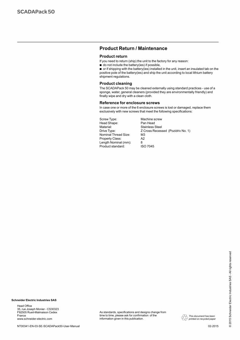
As standards, specifications and designs change from time to time, please ask for confirmation of the information given in this publication.
Schneider Electric Industries SAS
© 2
015
Sch
neid
er E
lect
ric In
dust
ries
SA
S -
All
right
s re
serv
ed
This document has been printed on recycled paper
NT00341-EN-03-SE-SCADAPack50-User-Manual 02-2015
Head Office35, rue Joseph Monier - CS30323F92505 Rueil-Malmaison CedexFrancewww.schneider-electric.com
Product Return / MaintenanceProduct returnIf you need to return (ship) the unit to the factory for any reason:
b do not include the battery(ies) if possible, b or if shipping with the battery(ies) installed in the unit, insert an insulated tab on the
positive pole of the battery(ies) and ship the unit according to local lithium battery shipment regulations.
Product cleaningThe SCADAPack 50 may be cleaned externally using standard practices - use of a sponge, water, general cleaners (provided they are environmentally friendly) and finally wipe and dry with a clean cloth.
Reference for enclosure screwsIn case one or more of the 6 enclosure screws is lost or damaged, replace them exclusively with new screws that meet the following specifications:
Screw Type: Machine screwHead Shape: Pan Head Material: Stainless Steel Drive Type: Z Cross Recessed (Pozidriv No. 1)Nominal Thread Size: M3Property Class: A2Length Nominal (mm): 8 Product standard: ISO 7045
SCADAPack 50