Embed Size (px)
Citation preview
8500111
SCADA Multidrop
Multiplexer
TABLE OF CONTENTS
SECTION 1 - DESCRIPTION ..........................................................................2
SECTION 2 - SPECIFICATIONS ....................................................................5
SECTION 3 - INSTALLATION ........................................................................7
SECTION 4 - CONTROLS AND INDICATORS..........................................12
SECTION 5 - NETWORK MANAGEMENT PORT .....................................14
SECTION 6 - INTERFACE SIGNALS AND CABLING.............................24
SECTION 7 - TROUBLESHOOTING ...........................................................29
SECTION 8 - WARRANTY..............................................................................31
Data Comm for Business, Inc.
PO Box 6329
Champaign, IL 61826-6329 January 6, 2009
(217) 897-6600 Firmware Version: 3.2
www.dcbnet.com
2
1. DESCRIPTION
The SCADA Multidrop Multiplexer (SMD) is designed for sharing one
multidrop radio, modem or DSU system with 2 or more multidrop
polling systems. With the SMD, one multidrop network can support
multiple protocols and systems, such as DNP, Modbus, etc. RTUs can
be polled on a multidrop system at the same time other polling takes
place for load management, automatic meter reading, etc.
Host and remote SMDs can be 1, 4, 8, 16, 24 or 32 port units. Most
SCADA applications use 1 and 4 port units. One port units are used
on systems that service only a single protocol. Different size SMDs
can be mixed on the same multidrop line.
The composite channel of the multiplexer can be synchronous or
asynchronous at speeds up to 115.2 Kbps async and up to 128 Kbps
sync. Ports on 1 and 4 port units can be set to speeds up to 57.6 Kbps.
Ports on 8 – 32 port units can be set up to 38.4 Kbps. All ports are
RS232. The device ports can be used with just 3-wires (send, receive
and ground) or with full RTS/CTS and Carrier Detect control.
Optional RS422 adapters are available for the ports.
The SCADA Multidrop Multiplexer (SMD) sends data from host device
ports to the remote units as soon as the data comes into the host ports.
All the remote SMDs receive the data. The host SMD is also
continually checking the remote SMDs to retrieve any data from remote
ports. The SMD unit also keeps together blocks of data coming into the
ports. This insures that polling protocols such as Modbus RTU will
work successfully with the SCADA Multidrop Multiplexer.
The SMD can also be used to access serial management ports or
control power to devices at remote locations. Four port units can be
used with DCB EtherBridge units to bridge LAN connections to
remote sites.
Setup of the SMD is simple, using a terminal or PC connected to the
network management port. Easy to use English command menus are
used to set port speeds, unit IDs (if desired), the drop number for the
remote multiplexers, sync or async network operation, and control
lead timing parameters. The management port can also be used to
check system operation, including port activity, link errors, port
monitoring, etc. The management port commands are short, simple
and comprehensive.
3
Some features of the SCADA Multidrop Multiplexer include:
• Synchronous or asynchronous composite
• Multiplex over radios, modems, DSUs, etc
• Multiplex multiple separate polling systems
• Use for SCADA RTU control, metering, load management, etc.
• Each port can have a different protocol and application
• One port unit available for single protocol applications
• Each port can be set to a different speed
• Host to remote port speed conversion
• Add remote Ethernet with the DCB EtherBridge
• Access Port function allows direct terminal communication
with devices at any remote Drop.
• Remote control power module (APS-01) supported through
Access Port function
• Standalone, rackmount or wallmount
Options:
• Built-in 56 / 64 Kbps DSU/CSU
• Built-in wireless modem (1 and 4 port models only)
• DC power options are also available
4
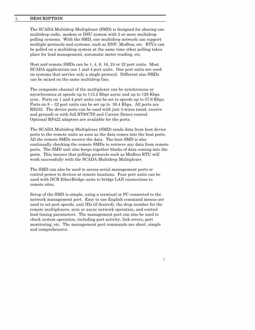
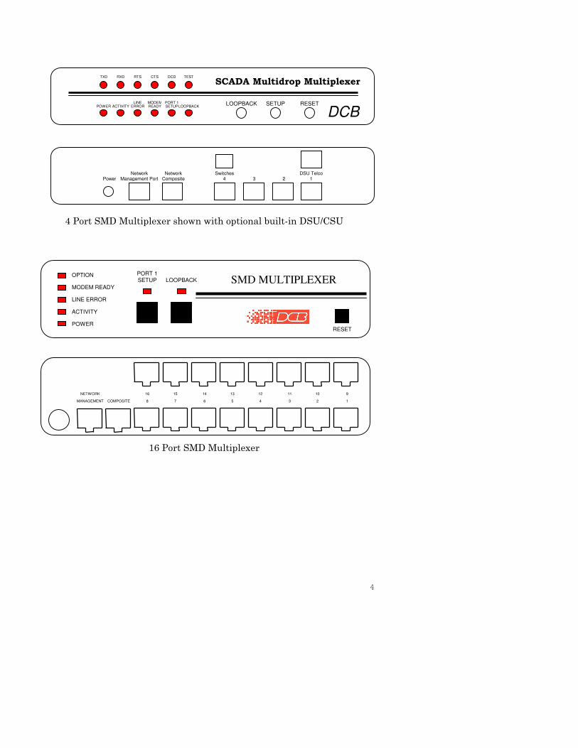
4 Port SMD Multiplexer shown with optional built-in DSU/CSU
16 Port SMD Multiplexer
TXD RXD RTS CTS DCD TEST
SCADA Multidrop Multiplexer
LINE MODEM PORT 1POWER ACTIVITY ERROR READY SETUPLOOPBACK
LOOPBACK SETUP RESET
DCB
Network Network Switches DSU TelcoPower Management Port Composite 4 3 2 1
RESET
SMD MULTIPLEXEROPTION
MODEM READY
LINE ERROR
ACTIVITY
POWER
PORT 1SETUP LOOPBACK
NETWORK 16 15 14 13 12 11 10 9
MANAGEMENT COMPOSITE 8 7 6 5 4 3 2 1
5
2. SPECIFICATIONS
2.1 Data Ports
Port Speeds
Asynchronous only
300, 600, 1200, 2400, 4800, 9600, 19,200, or 38,400
(and 57,600 bps on 1 and 4 port units)
Port Rate SelectionSelected per port through network management port controlwith an asynchronous terminal.
InterfaceCCITT V.24, RS-232D, implemented in RJ-45, 8 positionconnectors. (RS-561 standard physical pin-out used on RJ-45connectors)
2.2 Composite Port
Speed
Synchronous up to 128 Kbps
Asynchronous from 300 to 115,200 bps
Interface
RS-232D, implemented in RJ-45, 8 position connector
2.3 Physical / Electrical
10¼" W x 9¾" D x 2½" H (1 thru 16 port models)
10¼" W x 9¾" D x 4¼" H (24 and 32 port models)
120 VAC external power supply
Optional DC and 240VAC power supplies available
470 ma
2.4 Environmental
Operation: -40 to +70° C, 10 to 95% relative humidity
Storage: -40 to +85° C, 10 to 95% relative humidity
2.5 Optional Built-In DSU/CSU Specifications
Compatible with Common Carrier digital signalling
56 or 64 Kbps
4 wire digital line
Can be used as high speed 4 wire line driver in 56K mode
6
2.6 Network Management Port Commands
Show Port ConfigurationShow MapShow Network StatusChange Port ConfigurationChange MapChange Delay TimeoutConfigure NetworkConfigure OptionsConfigure Radio ModemShow / Change mux and port IDsSet NMP PasswordSet Access Port disconnect stringSet Access Port promptActivity CountersZero Activity CountersDrop Activity CountersTest Tools
Capture Access PortMonitor Port TxMonitor Port RxNMP ParityPing DropPower Port CommandsReset Mux
TypeRepeat Last CommandDisconnect NMP
2.7 Other Specifications
Operating ModesHost or DropFull or Half Duplex Network Modem
Front Panel IndicatorsPowerActivityLine ErrorModem ReadyPort 1 SetupLoopback (disabled)
Front Panel SwitchesLoopback (disabled)SetupReset
7
3. INSTALLATION
3.1 Unpacking
Remove the multiplexer from the shipping container and examine itcarefully for external damage. If shipping damage is apparent, notifythe shipper immediately.
The following accessories are included with all multiplexers:
• external power supply (AC only)
• manual
• warranty, maintenance contract and repair information
• Modem to Composite cable (black) for connecting the unit toan external modem or DSU/CSU
• Network Management Port cable (green) for connecting thenetwork management port to an asynchronous terminal or PCfor configuration
• If your unit has the optional built-in DSU/CSU, a cable isincluded for connection to the phone line.
3.2 Setup
The composite port must be configured properly for the type of link
used (Sync or Async). In addition, each device port must have the
proper speed settings. This is done using the network management
port CN and CP commands (see Section 5).
The default mode for SMD multiplexers is Host. In the Host unit, you
must configure the Drop Map. This is what tells the Host which
Drops to poll. Use the CM command.
Units used as Drops must be configured as “DROP” using the CO
command. Drop numbers can range from 1 to 63. After the drop
number is entered, you will have the option to enable Transparent
mode. Transparent mode is used during initial deployment of the
SMD multiplexers. In transparent mode data is passed directly from
device port 1 to the composite port as though the multiplexer was not
in the circuit (transparent). NOTE: Port 1 is the only port that is
connected in Transparent mode. This allows all of the Drop
multiplexers to be installed while maintaining SCADA
communication back to the host. After all the remote drops are
installed, the Host multiplexer is configured and installed. When the
Host starts polling the Drops they automatically switch to
multiplexing mode and the system comes on-line using the SMD
units.
8
3.3 Using Leased Line Modems
In this section, a reference to modem includes modems or DSU/CSUsfor 4-wire leased line installations.
Connect the modems to the phone line and power ON the modems.Confirm the presence of carrier at each modem. If carrier is notdetected at both ends, recheck the option settings. If carrier is still notpresent, check the cable from the telephone line to the modem. Ifeverything is correct and still no carrier call the manufacturer of themodem or contact the telephone company for assistance.
Connect the multiplexer composite port to the modem. A two foot RJ45to DB-25 male cable connects the composite port of the unit (the RJ45connector second from the left when viewed from the rear) to the dataport of the modem (usually a DB-25 female connector). See Section 6 forcabling information.
Connect the multiplexers to power.
3.4 Optional Built-In 56 / 64 Kbps DSU/CSU
The optional DSU/CSU in the 1 and 4 port models is configured usingDIP switches accessable from the rear of the unit. See Section 4 for adescription and location of these switches. The default settingsshould be correct for most applications.
In the 8, 16, 24 and 32 port models, the optional DSU/CSU isconfigured using the CN command. See paragraph 5.4.8.
For line driver applications over customer owned wire (56K only), setone unit for Master Clock (Line Driver 56) and the other unit to SlaveClock (StdClk 56).
3.5 Optional Built-In Wireless Modem (1 and 4 port models only)
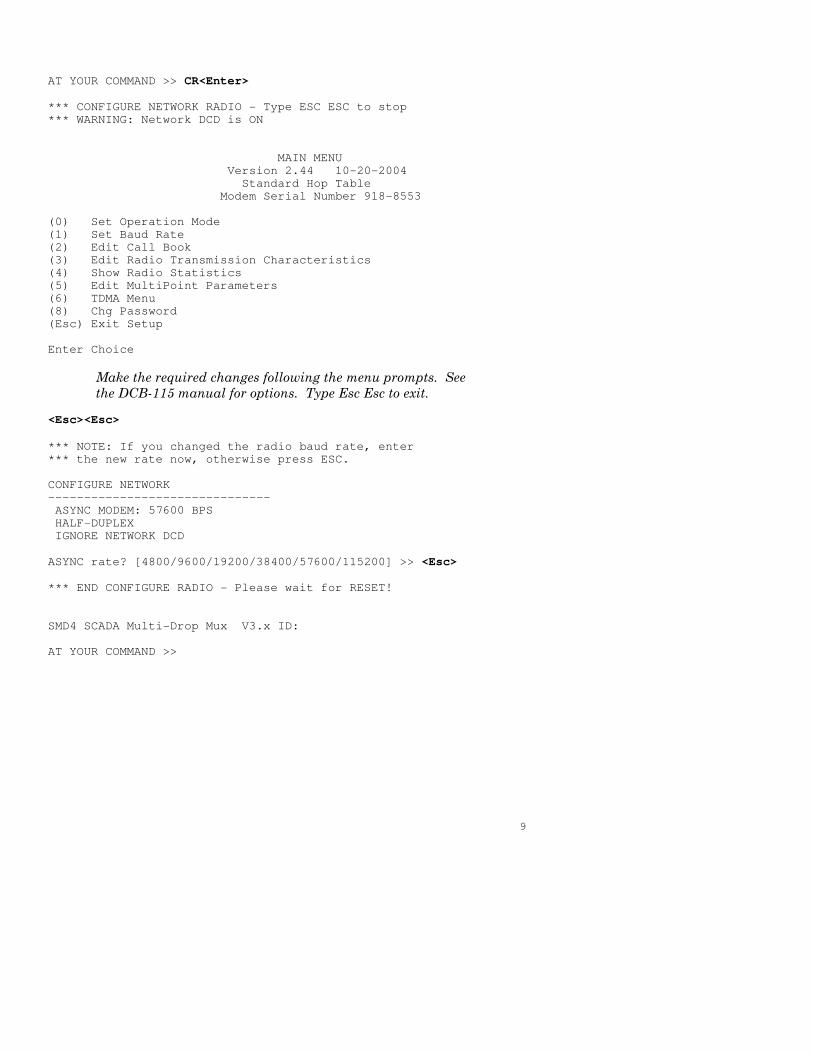
Your SMD multiplexer with internal wireless modem was configured
at the factory to work in most applications. If changes are required to
the modem settings, connect a terminal to the multiplexer network
management port (See Section 5) and follow the procedure on the
next page. User responses are shown in BOLD.
9
AT YOUR COMMAND >> CR<Enter>
*** CONFIGURE NETWORK RADIO - Type ESC ESC to stop
*** WARNING: Network DCD is ON
MAIN MENU
Version 2.44 10-20-2004
Standard Hop Table
Modem Serial Number 918-8553
(0) Set Operation Mode
(1) Set Baud Rate
(2) Edit Call Book
(3) Edit Radio Transmission Characteristics
(4) Show Radio Statistics
(5) Edit MultiPoint Parameters
(6) TDMA Menu
(8) Chg Password
(Esc) Exit Setup
Enter Choice
Make the required changes following the menu prompts. See
the DCB-115 manual for options. Type Esc Esc to exit.
<Esc><Esc>
*** NOTE: If you changed the radio baud rate, enter
*** the new rate now, otherwise press ESC.
CONFIGURE NETWORK
-------------------------------
ASYNC MODEM: 57600 BPS
HALF-DUPLEX
IGNORE NETWORK DCD
ASYNC rate? [4800/9600/19200/38400/57600/115200] >> <Esc>
*** END CONFIGURE RADIO - Please wait for RESET!
SMD4 SCADA Multi-Drop Mux V3.x ID:
AT YOUR COMMAND >>
10
3.6 Access Port Operation
At the Host, ports can be configured as Access ports. When
configured as an Access port, a direct connection is established
between that port and the same number port on any active Drop. To
use an Access port you may either connect a terminal directly to the
port or use the Network Management Port CA# command from the
management terminal. In either case you will be prompted for a Drop
number. Enter the Drop number that you wish to connect to and you
now have a direct connection to that Drop.
The accessed port at the Drop is configured as a data port and can be
connected to an equipment console, management or configuration
port to allow remote access to the equipment.
3.7 Power Port Operation
Drop ports may be configured as Power ports for connection to a DCB
APS-01 power control unit. This allows for remote power control of
equipment at Drop locations.
The Drop port must be configured as a Power Port (PP) to properly
control the APS-01. Use the CP command to configure the port. Four
power port commands are available for local testing using the Drop
Network Management Port. The commands are ON#, OFf#, CYcle#
and STatus where # is the Power Port number (1-32). The port
number is optional after it is entered the first time. The STatus
command will display the current state of all ports configured as
Power Ports. These commands are provided for testing during initial
installation of the APS-01.
At the Host, power ports are controlled using an Access Port.
Therefore, the Host port number corresponding to the Drop Power
Port must be configured as an Access Port. To control the Drop Power
Port you may either connect a terminal directly to the Host Access
Port or use the NMP CA# command from the management terminal.
When connected, you will be prompted for a Drop number. Enter the
number of the Drop you wish to access followed by a Power Port
command (i.e. 1ON to turn power ON at Drop 1). The Drop number is
optional after it is entered the first time and all subsequent power
port commands will go to that same Drop. To access a different Drop,
enter a new Drop number. If you are connected using the CA#
command from the NMP port, type Esc Esc to end the port capture.
11
3.8 Cabling
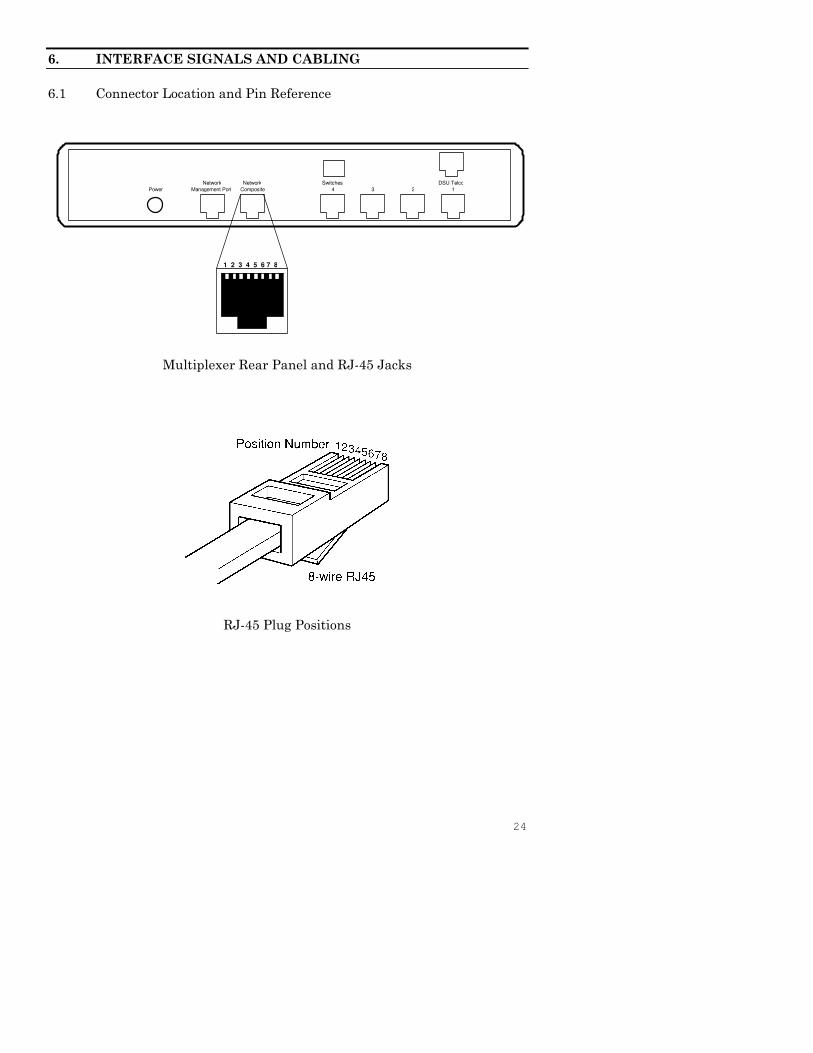
Cabling between the multiplexer and the computer ports or terminaldevices is a common source of installation problems. The multiplexermust have data from attached terminal devices or computer ports, asan input on position 6 of the RJ45 connector. Data from themultiplexer to any attached equipment will be transmitted onposition 5 of the RJ45 connector. See paragraph 6.1 for positionlocations on the RJ45 connector. See Section 6 to determine thecorrect cables for your computer and terminal devices.
3.9 Resetting Factory Defaults
The factory default settings for the multiplexer ports are as follows:
Device Ports:
Type Data
Loop OFF
Rate 9600
Composite Port:
Modem type ASYNC
Rate 9600 bps
Half Duplex
Ignore Network DCD
Mode:
1 and 4 port models 8, 16, 24 and 32 port models
Host Mode Host Mode
DROP polling enabled PORT polling enabled
Poll timeout: 500 ms Poll timeout: 25 ms
Poll restart: 2 (x 15 sec) Remote Response timeout: 500 ms
DCD to Rx data delay: 0 ms Poll restart: 2 (x 15 sec)
Maximum CTS allowed: 8
DCD to Rx data delay: 0 ms
To reset the unit to factory defaults use the !R command from thenetwork management port OR perform the following steps using thefront panel switches:
1. Depress and hold the SETUP switch then depress and release theRESET switch.
2. Be sure to continue to hold the SETUP switch until the unitcompletes the reset and the lights return to normal.
3. All port settings should be at the factory defaults. Use the SC(Show Configuration) command to check the settings.
12
4. CONTROLS AND INDICATORS
4.1 Switches
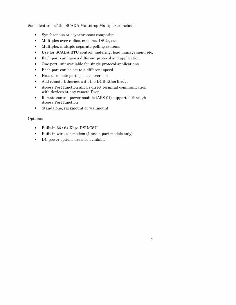
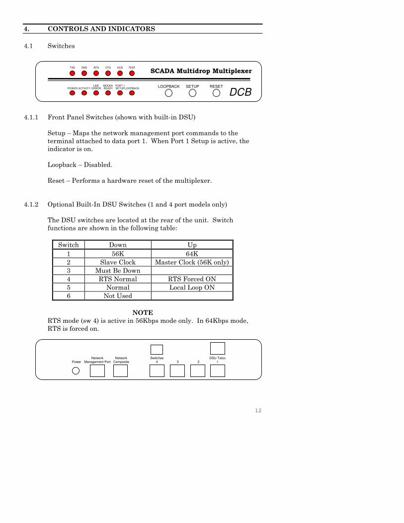
4.1.1 Front Panel Switches (shown with built-in DSU)
Setup – Maps the network management port commands to the
terminal attached to data port 1. When Port 1 Setup is active, the
indicator is on.
Loopback – Disabled.
Reset – Performs a hardware reset of the multiplexer.
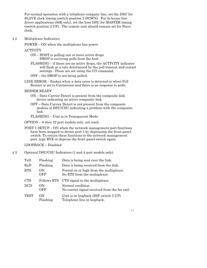
4.1.2 Optional Built-In DSU Switches (1 and 4 port models only)
The DSU switches are located at the rear of the unit. Switch
functions are shown in the following table:
Switch Down Up
1 56K 64K
2 Slave Clock Master Clock (56K only)
3 Must Be Down
4 RTS Normal RTS Forced ON
5 Normal Local Loop ON
6 Not Used
NOTE
RTS mode (sw 4) is active in 56Kbps mode only. In 64Kbps mode,
RTS is forced on.
Network Network Switches DSU TelcoPower Management Port Composite 4 3 2 1
TXD RXD RTS CTS DCD TEST
SCADA Multidrop Multiplexer
LINE MODEM PORT 1POWER ACTIVITY ERROR READY SETUPLOOPBACK
LOOPBACK SETUP RESET
DCB
13
For normal operation with a telephone company line, set the DSU for
SLAVE clock timing (switch position 2 DOWN). For in-house line
driver applications (56K only), set the host DSU for MASTER timing
(switch position 2 UP). The remote unit should remain set for Slave
clock.
4.2 Multiplexer Indicators
POWER – ON when the multiplexer has power
ACTIVITY
ON – HOST is polling one or more active dropsDROP is receiving polls from the host
FLASHING – if there are no active drops, the ACTIVITY indicatorwill flash at a rate determined by the poll timeout and restartsettings. These are set using the CO command.
OFF – the DROP is not being polled.
LINE ERROR – flashes when a data error is detected or when PollRestart is set to Continuous and there is no response to polls.
MODEM READY
ON – Data Carrier Detect is present from the composite linkdevice indicating an active composite link.
OFF – Data Carrier Detect is not present from the compositemodem or DSU/CSU indicating a problem with the compositelink.
FLASHING – Unit is in Transparent Mode.
OPTION – 8 thru 32 port models only, not used.
PORT 1 SETUP – ON when the network management port functionshave been mapped to device port 1 by depressing the front panelswitch. To return these functions to the network managementport, type BYE or depress the front panel switch again.
LOOPBACK – Disabled
4.3 Optional DSU/CSU Indicators (1 and 4 port models only)
TxD Flashing Data is being sent over the link.
RxD Flashing Data is being received from the link.
RTS ON
OFF
Forced on or high from the multiplexer.
No RTS from the multiplexer.
CTS Follows RTS CTS signal to the multiplexer.
DCD ON
OFF
Normal condition.
No carrier signal received from the far end.
TEST ON
Flashing
Unit is in loopback (DIP switch 5 UP)
Telephone line in loopback.
14
5. NETWORK MANAGEMENT PORT
5.1 Introduction
The Network Management port (NMP) is used to configure the
multiplexer for proper operation. This connection must be used to
configure the composite and device ports. The NMP can also be used
to configure remote multiplexer ports after a link is established
between the host and drop sites.
5.2 Connections and Setup
Connection to the NMP is made either through a port on the rear of
the multiplexer or by using Port 1 Setup.
5.2.1 Port 1 Setup
The easiest way to access the NMP functions is by using a terminal
connected to port 1 of the multiplexer. A switch located on the front
panel performs this function. See paragraph 4.1.1 for information.
This option cannot be used if a printer is connected to port 1.
5.2.2 Dedicated Terminal or PC
The NMP functions are also available through a port on the rear of
the unit labeled Network Management Port. To connect a dedicated
terminal to this port, use the green cable provided and the
appropriate adapter for either a terminal or PC. Set the terminal
device for 9600 bps, 8 data bits, no parity, one stop bit and no flow
control.
5.2.3 Dedicated Modem
For remote access to NMP functions, a dial-up modem may be
connected to the Network Management Port. You must fix the DTE
interface speed of the modem at 9600 bps, 8 data bits, no parity and
one stop bit. Refer to your modem manual for appropriate setup
procedures. Use the appropriate cable from paragraph 6.3.3 for
connection.
15
5.3 Using the Network Management port
To activate the NMP, press the ENTER key. When you see AT
YOUR COMMAND >>, the NMP is active and ready for your
commands. Type H <Enter> to display the command set.
5.4 Commands
NOTE
The commands listed below are for a unit configured as a HOST.
Some commands are not available for units configured as DROPs.
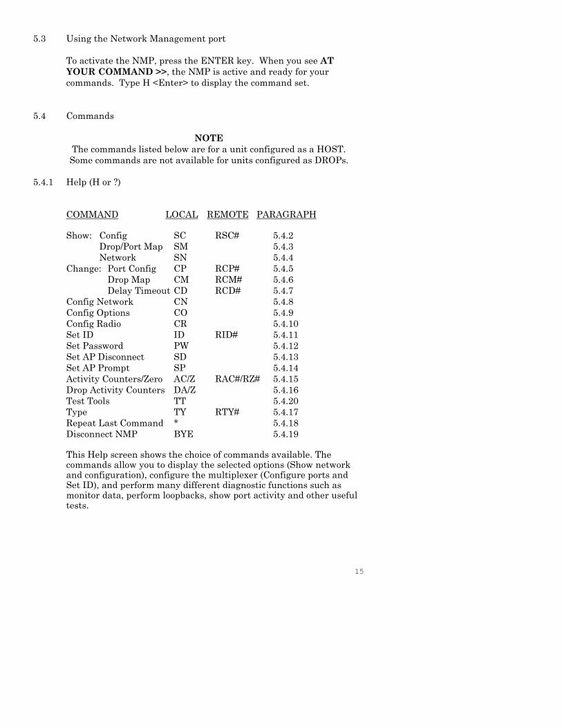
5.4.1 Help (H or ?)
COMMAND LOCAL REMOTE PARAGRAPH
Show: Config SC RSC# 5.4.2
Drop/Port Map SM 5.4.3
Network SN 5.4.4
Change: Port Config CP RCP# 5.4.5
Drop Map CM RCM# 5.4.6
Delay Timeout CD RCD# 5.4.7
Config Network CN 5.4.8
Config Options CO 5.4.9
Config Radio CR 5.4.10
Set ID ID RID# 5.4.11
Set Password PW 5.4.12
Set AP Disconnect SD 5.4.13
Set AP Prompt SP 5.4.14
Activity Counters/Zero AC/Z RAC#/RZ# 5.4.15
Drop Activity Counters DA/Z 5.4.16
Test Tools TT 5.4.20
Type TY RTY# 5.4.17
Repeat Last Command * 5.4.18
Disconnect NMP BYE 5.4.19
This Help screen shows the choice of commands available. Thecommands allow you to display the selected options (Show networkand configuration), configure the multiplexer (Configure ports andSet ID), and perform many different diagnostic functions such asmonitor data, perform loopbacks, show port activity and other usefultests.
16
5.4.2 Show (Unit) Configuration
The Show Config (SC) command shows the current network, mode,
and device port configuration settings for either the local or the
remote unit. A drop number is required with the RSC# command
from the host. Port numbers may be included with this command to
limit the port display. If no port numbers are included, settings for
all device ports are shown. Use this command to verify proper unit
configuration.
NOTE
Several commands allow device port numbers or port
number ranges to be included on the command line.
When port numbers are included, the syntax is as
follows:
(Command)1 Port 1
(Command)1,2,4 Ports 1, 2 & 4
(Command)2−4 Ports 2 thru 4
5.4.3 Show Drop / Port Map
The Show Drop Map (SM) command displays a list of all drops
mapped to the host. Up to 63 drops can be mapped to a single host.
Only mapped drops are polled by the host. The drop map is entered
using the CM command.
At a Drop, the command displays the Drop port mapping to the Host.
The port map is entered using the CM command.
5.4.4 Show Network (Configuration)
The Show Network (SN) command displays the current network(composite port) configuration. Sync or async, async speed, full orhalf duplex and modem DCD settings are displayed.
5.4.5 Change Port Configuration
The Change Port Config (CP / RCP#) command sets the loopback, rate
and port type for each device port. With optional firmware, ports can
be set to 8 data bits plus EVEN or ODD parity.
17
At the Host, port type can be Data port or Access port. See paragraph
3.6 for a description of Access Port operation. In units with 8 or fewer
ports, a port can also be configured as a Bridge port. Bridge port
configuration is required when a DCB EtherBridge is connected to
the Host port.
At a Drop, port type can be Data port, Access port, Power port or
Bridge port. The Bridge port setting is required when a DCB
EtherBridge is connected to the Drop port. See paragraph 3.7 for a
description of Power Port operation.
Follow the prompts and examples on the screen to select the port(s)
and parameter(s) you wish to change. One or more ports may be set
with a single command by selecting a range of port numbers. The
factory default setting is loop off, 9600 bps, data.
The RCP# command may be used from the host to set device ports on
drops. An active drop number (#) is required. If no drop number is
supplied, the last drop accessed by any remote command will be used.
5.4.6 Change Drop / Port Map
At the Host, use the CM command to enter or edit the drop map.
Valid drop numbers are 1 – 63. Only drops that are mapped will be
polled for data by the host.
At a Drop, the command is used to enter or edit the port map. Drop
ports may be mapped to any Host port. Valid Host port numbers are
1 – 32 and each Host port can appear only once in the port map.
The port map can also be changed from the Host using the RCM#
command where # is a valid Drop number.
5.4.7 Change Delay Timeout
At the HOST and DROP
This command (CD/RCD#) is used to change two device port timeout
parameters, DCD to Rx data delay and DCD holdover delay. These
delays may be adjusted to insure data block integrity.
18
DCD to RX data delay can be set from 0 to 250ms. This is the time
between Port DCD being asserted and data being sent out the port to
the attached device. For example, if you are using a 202T modem off
a drop port, you may want to set the DCD to RxD delay to match the
modem RTS/CTS delay and use the SMD DCD signal to drive the
modem RTS signal. If this parameter is set to zero (0), port DCD is
forced ON.
If DCD to RxD is NOT set to zero (forced on), the DCD Holdover delay
may be set to a value between 2 and 250ms. This will hold port DCD
on for the designated time after the port buffer empties. This can
help insure that all data gets to the attached device.
Use RCD# to change drop timeouts from the host.
At a DROP
At a Drop, there are two additional parameters that can be changed.
They are Buffer Clear timeout and Port buffer Smart Discard.
Buffer Clear timeout. can be set from 100 ms to 10 seconds. The
default setting is 2.5 seconds. If a host poll is not received within the
timeout period after a block is buffered, that block is discarded. It is
recommended that the drop Buffer Clear timeout be set to
approximately the same value as the host computer poll timeout.
In addition, you can enable or disable Port buffer Smart Discard.
When Port buffer Smart Discard is enabled, all buffered port data is
discarded when new data arrives from the host for that port. This
prevents old port data from going to the host when a new poll arrives.
5.4.8 Configure Network
The Configure Network command (CN) allows configuration of the
multiplexer composite port for asynchronous or synchronous
operation, full or half duplex and ignore modem DCD (yes/no). In 8
thru 32 port models, the command is also used to set the optional
DSU/CSU mode of operation.
When set for HALF DUPLEX, network RTS toggles and the mux
waits for CTS before sending. It may also wait for DCD (see below).
If set for HALF DUPLEX and IGNORE DCD=YES, then the host and
drop toggle network RTS and wait for CTS before sending. DCD is
not tested when blocks are received on the network port.
19
If set for HALF DUPLEX and IGNORE DCD=NO, then the host and
drop wait for DCD to turn OFF before they turn RTS ON to send a
block. In addition, DCD must be ON when an RX block arrives at the
network port.
When set for FULL DUPLEX, network RTS is always ON and
network CTS is ignored.
If set for FULL DUPLEX and IGNORE DCD=YES, then the host
sends whenever it is ready to send a poll, and the drop responds
immediately when it is polled. In addition DCD is not tested when
blocks are received on the network port.
If set for FULL DUPLEX and IGNORE DCD=NO, then the host and
drop check for DCD ON when a new block begins. If DCD is OFF
when a new block starts, the block is ignored.
5.4.9 Configure Options
The Configure Options (CO) command configures the SMD as either
HOST or DROP.
If HOST is selected, the following parameters may be set:
Enable Port Polling (Y/N) Port polling may increase your systems
efficiency if you have 8 or more drops or an SMD 8 or larger
unit at the host.
Poll Timeout (ms) – the amount of time the host will wait for a
response from a drop. After seven polls with no response, the
drop is removed from the poll sequence until the poll restart
timer expires.
If Port Polling is enabled, a Remote Response timeout can also be
set. After the SMD Host sends your data to a Drop port, the
Remote Response timeout is the number of milliseconds the
Host keeps asking the drops for the response data. This
should be set to a value less than or equal to the host
computer timeout.
Poll Restart time (n x 15 sec) – every n x 15 seconds, the host will
re-poll timed-out drops and attempt to restart them. Enter 0
(zero) to disable or C for continuous polling.
Maximum port CTS allowed [1-32] (8 thru 32 port models only)
If DROP is selected, the following parameters may be set:
Drop number (1 – 63)
Enable Transparent mode (Y/N) See paragraph 3.2.
20
5.4.10 Configure Radio (1 and 4 port models only)
The Configure Radio command (CR) establishes a direct connection
between the network management port and the optional built-in
wireless modem. The command is used to change configuration
settings in the wireless modem. See paragraph 3.5.
5.4.11 Set ID
The Set ID (ID/RID#) command allows you to set or change the local
multiplexer (name or location) and device port identifiers. IDs can be
a maximum of 15 characters in length. Pressing <Enter> with no
entry will leave the ID unchanged. This is for documentation only
and is not required for proper operation of the multiplexer. Use the
RID# command to set/change IDs of drop multiplexers from the host.
5.4.12 Set Password
Use the Set Password (PW) command to set a password for access to
the network management port. The password may be up to 15
characters long and is case sensitive.
To clear the password, type DELETE at the PW prompt or reset the
unit to defaults as described in paragraph 3.6.
5.4.13 Set Access Port Disconnect string (Host only if Access port configured)
The SD command is used to set the disconnect string used by Access
ports. The disconnect string is used to disconnect from the current
drop. The default is ^D^D^D (Ctrl D). To change the disconnect
string, type SD and enter the new characters. Control (Ctrl)
characters may be entered by holding the Ctrl key and pressing the
character key. If no Access ports are configured, this command is not
available.
5.4.14 Set Access Port Prompt (Host only if Access port configured)
This command (SP) is used to set the Access port prompt. This is the
prompt that you will see if a terminal is connected to a host Access
port or if the CA# command (see paragraph 5.4.22) is used to connect
to an Access port from the Network Management Port. The default is
“Access Drop#”. To change the prompt, type SP and enter the new
prompt. If no Access ports are configured, this command is not
available.
21
To use an Access port you must connect a terminal to that port on the
Host multiplexer either directly or by using the CA# command. At
the prompt, you must enter a Drop number (1-63). You will then
have a direct connection from the Host port to the same port number
on the drop. For example, if you define port 4 as an Access port and
connect your terminal to port 4, then access Drop 2, you will be
connected to whatever device is connected to port 4 on Drop 2. Port
IDs can be set to help document what type of device is connected to
which port.
5.4.15 Activity Counts / Zero
The Activity Counts (AC / RAC#) command shows transmit and
receive data statistics for all ports. The data are presented in terms
of blocks of information sent and received by the network and each
device port. Error counts are also shown. A range of ports may be
included with this command to reduce the number of ports shown.
The Z and RZ# commands are used to zero the counters so that
current activity can be monitored.
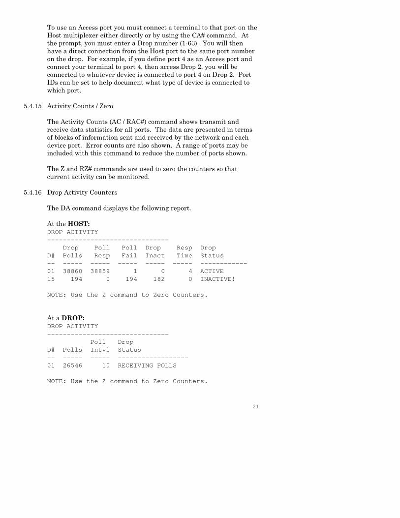
5.4.16 Drop Activity Counters
The DA command displays the following report.
At the HOST:
DROP ACTIVITY
-------------------------------
Drop Poll Poll Drop Resp Drop
D# Polls Resp Fail Inact Time Status
-- ----- ----- ----- ----- ----- ------------
01 38860 38859 1 0 4 ACTIVE
15 194 0 194 182 0 INACTIVE!
NOTE: Use the Z command to Zero Counters.
At a DROP:
DROP ACTIVITY
-------------------------------
Poll Drop
D# Polls Intvl Status
-- ----- ----- ------------------
01 26546 10 RECEIVING POLLS
NOTE: Use the Z command to Zero Counters.
22
5.4.17 Type
The Type (TY) command displays information about the local
multiplexer including firmware version, number of ports and
multiplexer ID. The Remote Type (RTY#) command is used at the
host to display similar information about a drop multiplexer.
5.4.18 Repeat Last Command
To repeat the last command, simply press the * key. This is handy
for repeating screens of constantly changing data.
5.4.19 Disconnect NMP
The BYE command toggles the CTS output from the Network
Management port. This is used to disconnect equipment such as dial-
up modems or the DCB Access Switch.
5.4.20 Test Tools
The Test Tools (TT) menu summarizes the test and troubleshooting
commands. These commands are listed separately to reduce the
clutter in the main help list, but are always available from the
command prompt.
COMMAND LOCAL REMOTE PARAGRAPH
Capture AP Port CA# 5.4.21
Monitor Port Tx MT# 5.4.22
Monitor Port Rx MR# 5.4.22
NMP Parity P 5.4.23
Ping DROP PING# 5.4.24
Power Port Commands ON# 5.4.25
OFF#
CYCLE#
STATUS
Reset Mux RESET RRESET# 5.4.26
5.4.21 Capture Access Port (Host only if Access port configured)
This command (CA#) is used from the Network Management Port to
connect to an Access port. A valid Access port number must be
included on the command line. This allows the NMP terminal to use
the Access port to connect to a remote device. See paragraphs 3.6 and
3.7. If no Access ports are configured, this command is not available.
23
5.4.22 Monitor Port TX or RX
The Monitor Port TX (MT#) command monitors data transmitted
from the selected device port to the corresponding port of the remote
multiplexer. The Monitor Port RX (MR#) command monitors data
received by the selected port from the corresponding port of the
remote multiplexer. A local port number must be included on the
command line.
Using these commands on an active line may cause errors when using
time sensitive protocols. Use the commands as a quick check to see if
data are being sent over the link. Do not try to use these commands
as a data line monitor.
When port monitor is active, two ESC characters are required to end
the test.
5.4.23 NMP Parity
The NMP Parity command (P) sets the parity for the network
management port. The factory default is SPACE (8,N,1).
5.4.24 Ping DROP / HOST
From the host, the PING# command pings a drop multiplexer and
displays the response time in milliseconds. From a drop, the PING
command displays the response time from the host.
5.4.25 Power Port Commands (Drop only if Power port configured)
Four commands are available at Drops to troubleshoot and test Power
ports. They are: ON# (turns power on), OFF# (turns power off),
CYCLE# (cycles power as determined by the current state and the
cycle time parameter) and STATUS (displays current status of all
Power ports). The # indicates the Power port number (1-4). See
paragraph 3.7.
5.4.26 Reset Mux
The Reset Mux (RESET) command performs a local multiplexer reset.
The RRESET# command can be used from the host to reset a drop
multiplexer.
24
6. INTERFACE SIGNALS AND CABLING
6.1 Connector Location and Pin Reference
Multiplexer Rear Panel and RJ-45 Jacks
RJ-45 Plug Positions
1 2 3 4 5 6 7 8
1234
DSU TelcoSwitchesNetwork Network
Power Management Port Composite
25
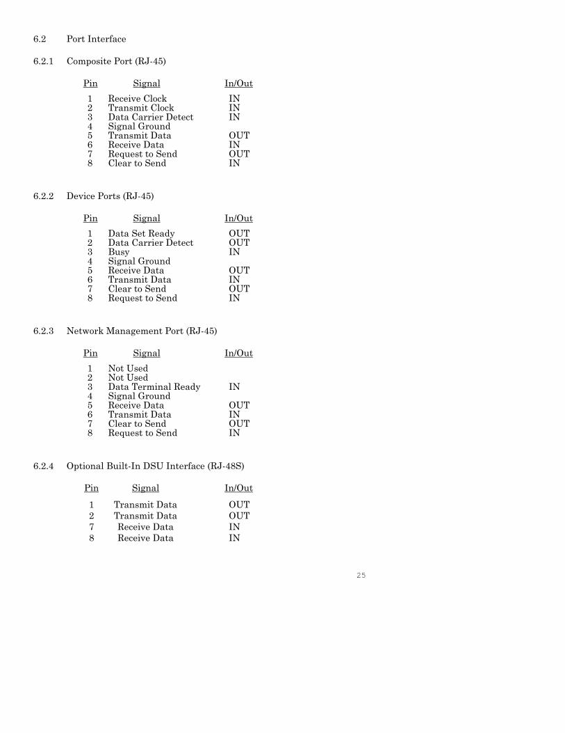
6.2 Port Interface
6.2.1 Composite Port (RJ-45)
Pin Signal In/Out
1 Receive Clock IN2 Transmit Clock IN3 Data Carrier Detect IN4 Signal Ground5 Transmit Data OUT6 Receive Data IN7 Request to Send OUT8 Clear to Send IN
6.2.2 Device Ports (RJ-45)
Pin Signal In/Out
1 Data Set Ready OUT2 Data Carrier Detect OUT3 Busy IN4 Signal Ground5 Receive Data OUT6 Transmit Data IN7 Clear to Send OUT8 Request to Send IN
6.2.3 Network Management Port (RJ-45)
Pin Signal In/Out
1 Not Used2 Not Used3 Data Terminal Ready IN4 Signal Ground5 Receive Data OUT6 Transmit Data IN7 Clear to Send OUT8 Request to Send IN
6.2.4 Optional Built-In DSU Interface (RJ-48S)
Pin Signal In/Out
1 Transmit Data OUT
2 Transmit Data OUT
7 Receive Data IN
8 Receive Data IN
26
1
2
3
4
5
6
7
8
6
8
20
7
3
2
5
4
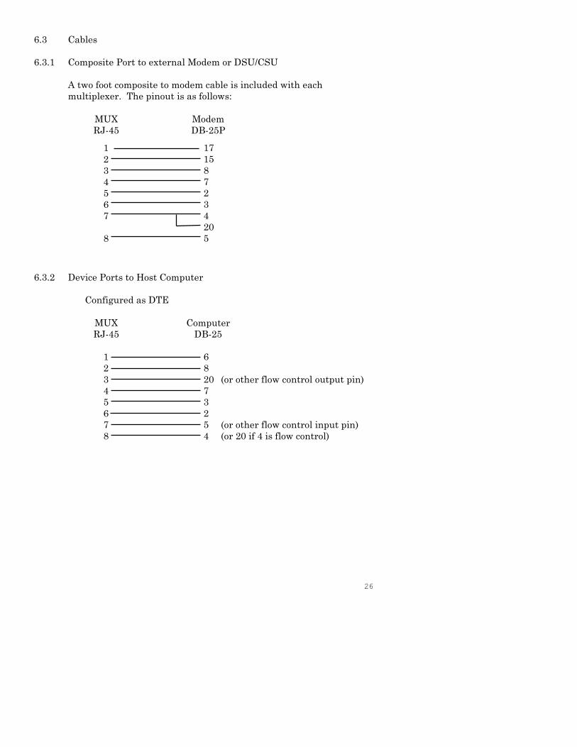
6.3 Cables
6.3.1 Composite Port to external Modem or DSU/CSU
A two foot composite to modem cable is included with each
multiplexer. The pinout is as follows:
MUX Modem
RJ-45 DB-25P
6.3.2 Device Ports to Host Computer
Configured as DTE
MUX Computer
RJ-45 DB-25
(or other flow control output pin)
(or other flow control input pin)
(or 20 if 4 is flow control)
1
2
3
4
5
6
7
8
17
15
8
7
2
3
4
20
5
27
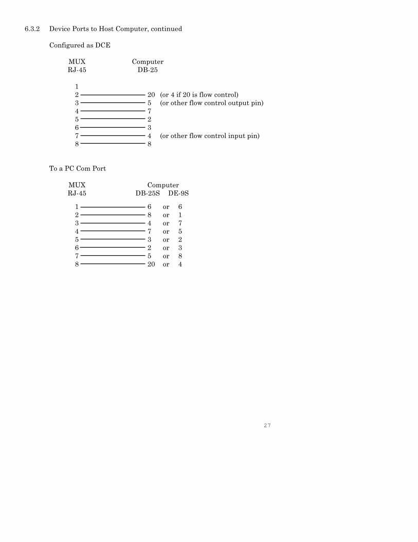
6.3.2 Device Ports to Host Computer, continued
Configured as DCE
MUX Computer
RJ-45 DB-25
(or 4 if 20 is flow control)
(or other flow control output pin)
(or other flow control input pin)
To a PC Com Port
MUX Computer
RJ-45 DB-25S DE-9S
1
2
3
4
5
6
7
8
20
5
7
2
3
4
8
1
2
3
4
5
6
7
8
6 or 6
8 or 1
4 or 7
7 or 5
3 or 2
2 or 3
5 or 8
20 or 4
28
3
4
5
6
7
8
8
7
2
3
4
20
5
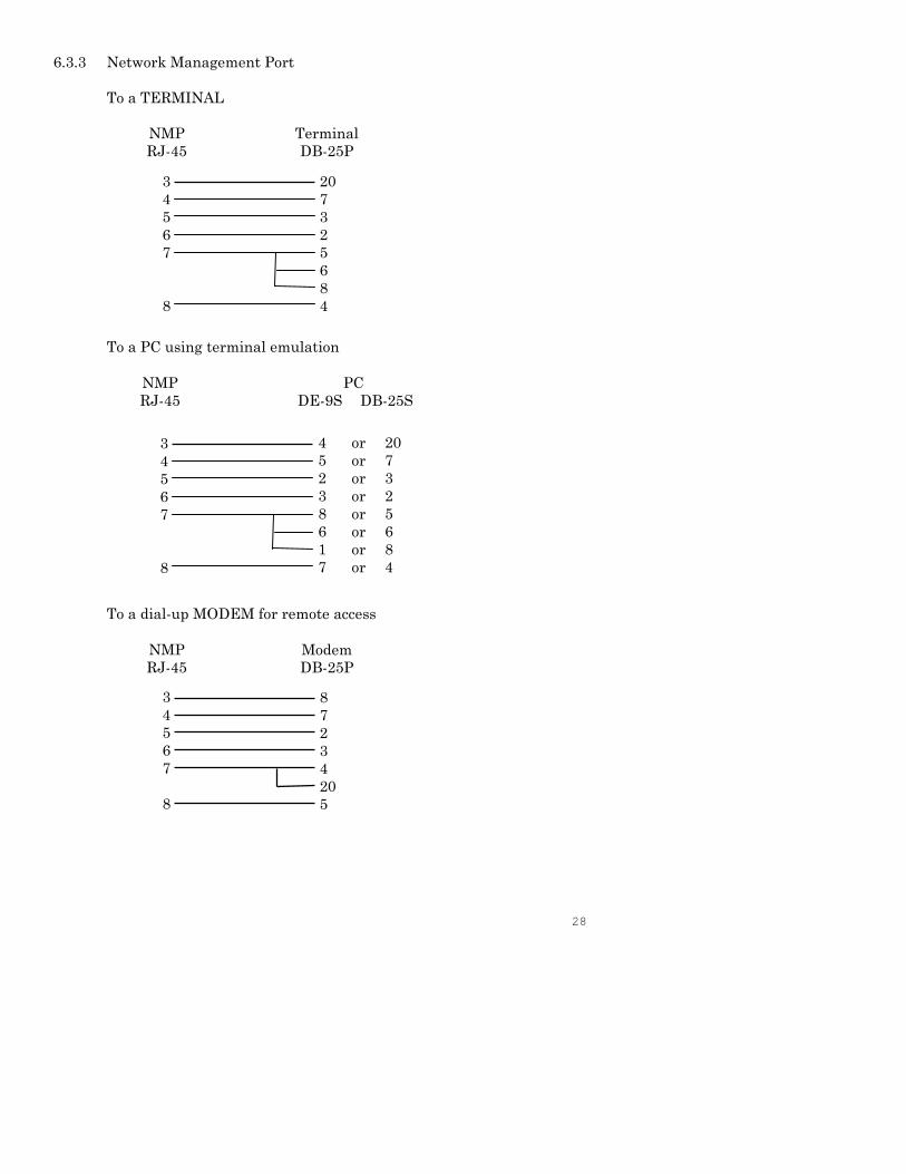
6.3.3 Network Management Port
To a TERMINAL
NMP Terminal
RJ-45 DB-25P
To a PC using terminal emulation
NMP PC
RJ-45 DE-9S DB-25S
To a dial-up MODEM for remote access
NMP Modem
RJ-45 DB-25P
20
7
3
2
5
6
8
4
3
4
5
6
7
8
4 or 20
5 or 7
2 or 3
3 or 2
8 or 5
6 or 6
1 or 8
7 or 4
3
4
5
6
7
8
29
7. TROUBLESHOOTING
7.1 General Approach
When troubleshooting problems, a rational plan can save you many
hours of frustration. The following is a brief outline of standard
troubleshooting procedures.
1. Gather the facts to determine the exact nature of the problem.
2. Draw a picture of the system showing the equipment at both
the host and remote ends and the phone lines or in-house
wiring. Use this as a reference to note your observations, test
steps and test results. A picture keeps you focused and often
saves duplicate effort.
3. Record the front panel indications before changing anything.
This is an important part of fact gathering
4. If you change anything, change only one thing at a time.
5. Use the built-in test functions, especially the loopback tests
and record your results.
7.2 Loopback Tests
It is best to begin loopback testing at the remote terminal and work
toward the host. If all the loopbacks are successful, the data
communications equipment and the terminal are working correctly.
Put the remote multiplexer port in loopback and have someone type
alpha characters on the keyboard of the affected terminal. If the
characters appear correctly on the screen, the port is working. Next
loop the associated port of the host multiplexer. If characters again
appear correctly, the communications link and the ports on both
multiplexers are working correctly. The problem then is with the
host computer port or the cable between the host computer and the
multiplexer.
Port loopbacks can be turned on and off from the Network
Management port of the multiplexer. If a NMP terminal is not
available, port loopback can be enabled using the Port 1 Setup
function of the remote multiplexer
30
7.3 Installation Troubleshooting, Modems or DSUs
First, set up the Modems or DSUs without connecting the
multiplexers. If DSUs are used they should be set to constant carrier,
also called forced Request To Send, or constant RTS.
Carrier Detect should be ON at both locations.
7.4 Installation Troubleshooting, Multiplexers
Before trying terminals, make sure the multiplexers are able to “see”
each other. Use the RTY command to verify a response from the
remote multiplexer. If you get a correct response to RTY, the link is
up and the multiplexers are communicating.
7.5 Installation Troubleshooting, Terminals
Terminal problems typically fall into four categories:
1. The terminal or printer gets no data
2. The terminal or printer gets “garbage” data
3. Blocks of data are lost
4. Terminals or printers seem to “hang”.
When a terminal gets no data, check to see the cables are wired
correctly and that flow control is set properly.
If the terminal gets “garbage” data, check the speeds of the host and
remote multiplexers, the terminal and the computer ports to make
sure they match.
7.6 Assistance
If you need assistance troubleshooting your system, contact DCB
customer support at (217) 897-6600 between 8:00 am and 5:00 pm
central time Monday through Friday.
31
8. WARRANTY
DCB multiplexers are warranted to be free of defects in materials and
workmanship for two years. Data Comm for Business will repair or
replace any equipment proven to be defective within the warranty
period. All warranty work is F.O.B. Dewey, IL. This warranty is
exclusive of abuse, misuse, accidental damage, acts of God or
consequential damages, etc. DCB liability shall not exceed the
original purchase price.
All equipment returned for repair must be accompanied by a Returned
Material Authorization (RMA) number. To receive an RMA number,
call (217) 897-6600 between the hours of 8 AM and 5 PM central time.
Equipment must be shipped prepaid to DCB and will be returned at
DCB's expense.
Ship returned items to:
Data Comm for Business
2949 County Road 1000E
Dewey, IL 61840
ATTN: your RMA number
Data Comm for Business, Inc.
PO Box 6329
Champaign, IL 61826-6329
Tel (217) 897-6600
Fax (217) 897-1331