Embed Size (px)
Citation preview
CONTENTS
Disclaimers 2Installation 3Communication Wiring to SERX3xxA 4SC3xxx LED Operation 5Wiring of Remote Inputs to SC3504E and SC3404E 5Model Chart 6Terminals, Wire Identification & Ratings 7Typical Wiring Example 8Dimensions 9
SC3000 SeriesLine Voltage Switching Relay Pack ControllersInstallation GuideCommercial and Hotel/Lodging HVAC Fan Coil Applications
NOTE: This document is for the SER7000 and SER8000 Controllers
Version 2
Schneider Electric | II-SC3000-A4.EN.07.2016.v3 www.schneider-electric.com/buildings July 2016
2
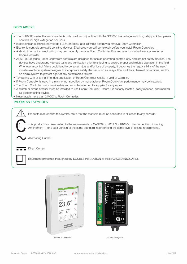
SER8300 Controller SC3000 Relay Pack
DISCLAIMERS
• The SER8000 series Room Controller is only used in conjunction with the SC3000 line voltage switching relay pack to operate controls for high voltage fan coil units.
• If replacing an existing Line Voltage FCU Controller, label all wires before you remove Room Controller.• Electronic controls are static sensitive devices. Discharge yourself completely before you install Room Controller.• A short circuit or incorrect wiring may permanently damage Room Controller. Ensure correct circuitry before powering up
Room Controller.• All SER8300 series Room Controllers controls are designed for use as operating controls only and are not safety devices. The
devices have undergone rigorous tests and verification prior to shipping to ensure proper and reliable operation in the field. Whenever a control failure could lead to personal injury and/or loss of property, it becomes the responsibility of the user/installer/electrical system designer to incorporate safety devices such as relays, flow switches, thermal protections, and/or an alarm system to protect against any catastrophic failures
• Tampering with or any unintended application of Room Controller results in void of warranty.• If Room Controller is used in a manner not specified by manufacturer, Room Controllerr performance may be impaired.• The Room Controller is not serviceable and must be returned to supplier for any repair.• A switch or circuit breaker must be installed to use Room Controller. Ensure it is suitably located, easily reached, and marked
as disconnecting device.• Never apply more than 24VDC to Room Controller.
IMPORTANT SYMBOLS
Products marked with this symbol state that the manuals must be consulted in all cases to any hazards.
This product has been tested to the requirements of CAN/CAS-C22.2 No. 61010-1, second edition, including Amendment 1, or a later version of the same standard incorporating the same level of testing requirements.
Alternating Current
Direct Current
Equipment protected throughout by DOUBLE INSULATION or REINFORCED INSULATION
Schneider Electric | II-SC3000-A4.EN.07.2016.v3 www.schneider-electric.com/buildings July 2016
3
INSTALLATION
All wiring must conform to the regulations of local and national electrical codes. Read the following instructions carefully before proceeding with the installation. Failure to follow the instructions could damage the product or cause a hazardous condition. Installation must be performed by a qualified service technician or electrician. Disconnect the power supply before installing in order to prevent electrical shock.
Installation
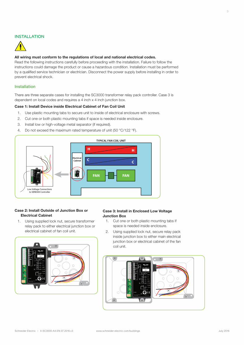
There are three separate cases for installing the SC3000 transformer relay pack controller. Case 3 is dependent on local codes and requires a 4 inch x 4 inch junction box.
Case 1: Install Device inside Electrical Cabinet of Fan Coil Unit
1. Use plastic mounting tabs to secure unit to inside of electrical enclosure with screws.
2. Cut one or both plastic mounting tabs if space is needed inside enclosure.
3. Install low or high-voltage metal separator (if required).
4. Do not exceed the maximum rated temperature of unit (50 °C/122 °F).
H
FAN FAN
C
H
CElectrical Cabinet
Low Voltage Connectionsto SER8300 Controller
TYPICAL FAN COIL UNIT
Case 2: Install Outside of Junction Box or Electrical Cabinet
1. Using supplied lock nut, secure transformer relay pack to either electrical junction box or electrical cabinet of fan coil unit.
Case 3: Install in Enclosed Low Voltage Junction Box
1. Cut one or both plastic mounting tabs if space is needed inside enclosure.
2. Using supplied lock nut, secure relay pack inside junction box to either main electrical junction box or electrical cabinet of the fan coil unit.
Schneider Electric | II-SC3000-A4.EN.07.2016.v3 www.schneider-electric.com/buildings July 2016
4
Replacing Old Fan Coil Controller
If replacing old line voltage fan coil Room Controller, label wires before removal of old Room Controller.
Proper Installation and Use
SC3000 series transformer relay packs can only be used as operating controls. If installed incorrectly, the device may fail or cause injury or loss of property. It is the responsibility of the end user to ensure the device is correctly installed by a certified professional, and proper safety precautions have been taken to prevent failures.
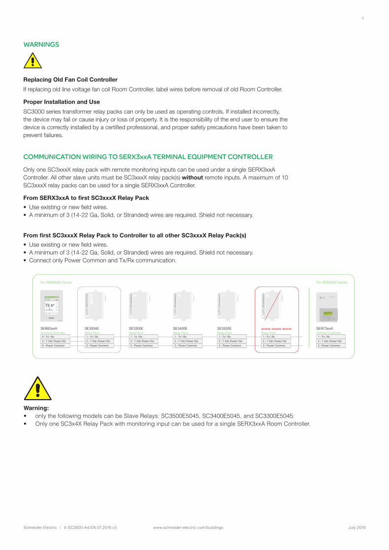
COMMUNICATION WIRING TO SERX3xxA TERMINAL EQUIPMENT CONTROLLER
Only one SC3xxxX relay pack with remote monitoring inputs can be used under a single SERX3xxA Controller. All other slave units must be SC3xxxX relay pack(s) without remote inputs. A maximum of 10 SC3xxxX relay packs can be used for a single SERX3xxA Controller.
From SERX3xxA to first SC3xxxX Relay Pack
• Use existing or new field wires.• A minimum of 3 (14-22 Ga, Solid, or Stranded) wires are required. Shield not necessary.
From first SC3xxxX Relay Pack to Controller to all other SC3xxxX Relay Pack(s)
• Use existing or new field wires.• A minimum of 3 (14-22 Ga, Solid, or Stranded) wires are required. Shield not necessary.• Connect only Power Common and Tx/Rx communication.
WARNINGS
Warning: • only the following models can be Slave Relays: SC3500E5045, SC3400E5045, and SC3300E5045. • Only one SC3x4X Relay Pack with monitoring input can be used for a single SERX3xxA Room Controller.
Tx/Rx
7 Vdc
Com
RUI 1
SCom
RBI 2
SS
RS
1
2
3
4
5
6
7
8
Tx/Rx
7 Vdc
Com
1
2
3
SER83xxATerminal Controller 4 - Tx / Rx
5 - 7 Vdc Power Hot
6 - Power Common
For SER8000 Series For SER7000 Series
SER73xxATerminal Controller 1 - Tx / Rx
2 - 7 Vdc Power Hot
3 - Power Common
SE3504ERelay Pack 1 - Tx / Rx
2 - 7 Vdc Power Hot
3 - Power Common
SE3300ERelay Pack 1 - Tx / Rx
2 - 7 Vdc Power Hot
3 - Power Common
Tx/Rx
7 Vdc
Com
1
2
3
SE3400ERelay Pack 1 - Tx / Rx
2 - 7 Vdc Power Hot
3 - Power Common
Tx/Rx
7 Vdc
Com
1
2
3
SE3500ERelay Pack 1 - Tx / Rx
2 - 7 Vdc Power Hot
3 - Power Common
Tx/Rx
7 Vdc
Com
1
2
3
SE3404E / SE3504E / SE3514E
Relay Pack 1 - Tx / Rx
2 - 7 Vdc Power Hot
3 - Power Common
Schneider Electric | II-SC3000-A4.EN.07.2016.v3 www.schneider-electric.com/buildings July 2016
5
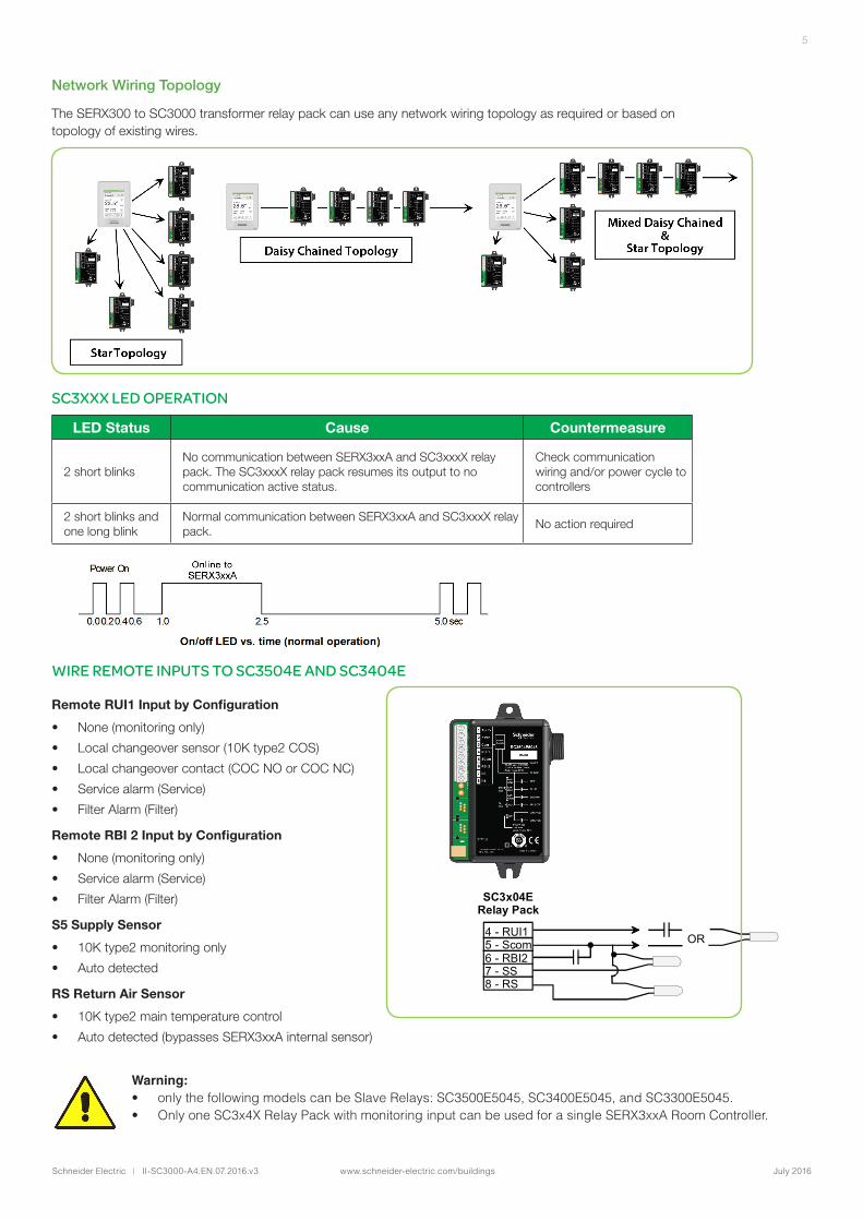
Network Wiring Topology
The SERX300 to SC3000 transformer relay pack can use any network wiring topology as required or based on topology of existing wires.
SC3x04ERelay Pack
OR 4 - RUI1 5 - Scom 6 - RBI2 7 - SS 8 - RS
WIRE REMOTE INPUTS TO SC3504E AND SC3404E
Remote RUI1 Input by Configuration
• None (monitoring only)
• Local changeover sensor (10K type2 COS)
• Local changeover contact (COC NO or COC NC)
• Service alarm (Service)
• Filter Alarm (Filter)
Remote RBI 2 Input by Configuration
• None (monitoring only)
• Service alarm (Service)
• Filter Alarm (Filter)
S5 Supply Sensor
• 10K type2 monitoring only
• Auto detected
RS Return Air Sensor
• 10K type2 main temperature control
• Auto detected (bypasses SERX3xxA internal sensor)
SC3XXX LED OPERATION
LED Status Cause Countermeasure
2 short blinksNo communication between SERX3xxA and SC3xxxX relay pack. The SC3xxxX relay pack resumes its output to no communication active status.
Check communication wiring and/or power cycle to controllers
2 short blinks and one long blink
Normal communication between SERX3xxA and SC3xxxX relay pack.
No action required
Warning: • only the following models can be Slave Relays: SC3500E5045, SC3400E5045, and SC3300E5045. • Only one SC3x4X Relay Pack with monitoring input can be used for a single SERX3xxA Room Controller.
Schneider Electric | II-SC3000-A4.EN.07.2016.v3 www.schneider-electric.com/buildings July 2016
6
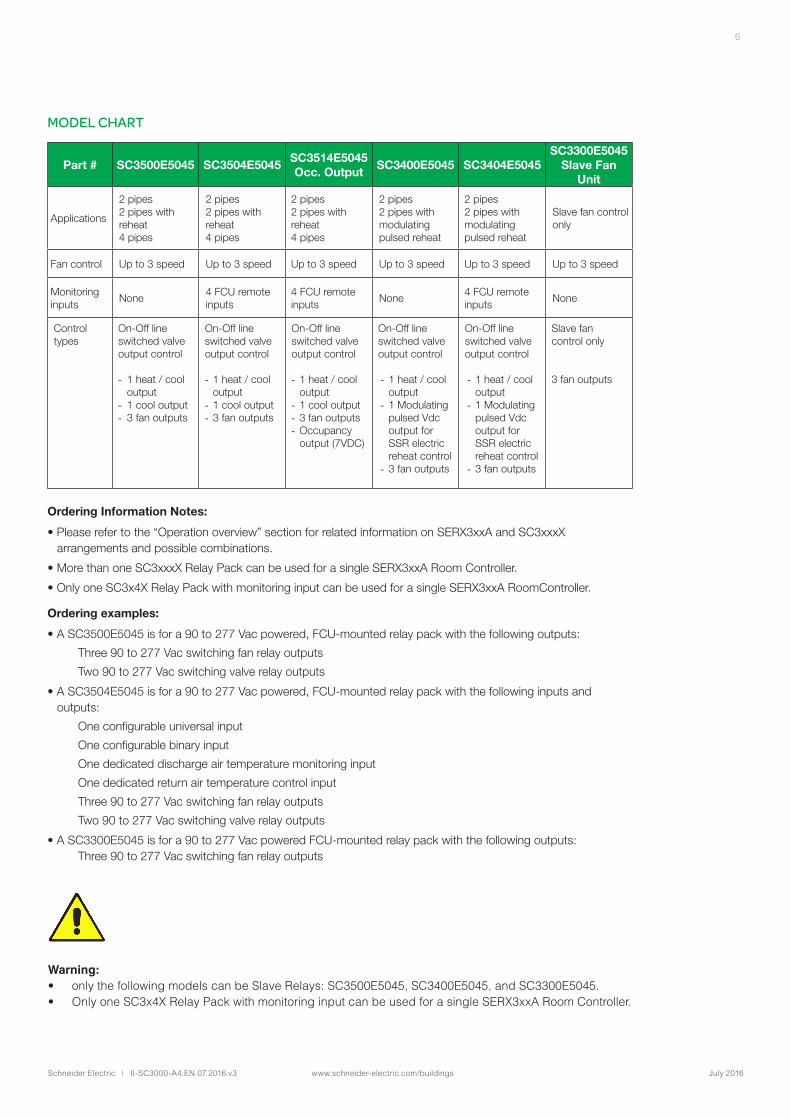
MODEL CHART
Part # SC3500E5045 SC3504E5045SC3514E5045Occ. Output
SC3400E5045 SC3404E5045SC3300E5045
Slave Fan Unit
Applications
2 pipes2 pipes with reheat4 pipes
2 pipes2 pipes with reheat4 pipes
2 pipes2 pipes with reheat4 pipes
2 pipes2 pipes with modulating pulsed reheat
2 pipes2 pipes with modulating pulsed reheat
Slave fan control only
Fan control Up to 3 speed Up to 3 speed Up to 3 speed Up to 3 speed Up to 3 speed Up to 3 speed
Monitoring inputs
None4 FCU remote inputs
4 FCU remote inputs
None4 FCU remote inputs
None
Control types
On-Off line switched valve output control
- 1 heat / cool output
- 1 cool output- 3 fan outputs
On-Off line switched valve output control
- 1 heat / cool output
- 1 cool output- 3 fan outputs
On-Off line switched valve output control
- 1 heat / cool output
- 1 cool output- 3 fan outputs- Occupancy
output (7VDC)
On-Off line switched valve output control
- 1 heat / cool output
- 1 Modulating pulsed Vdc output for SSR electric reheat control
- 3 fan outputs
On-Off line switched valve output control
- 1 heat / cool output
- 1 Modulating pulsed Vdc output for SSR electric reheat control
- 3 fan outputs
Slave fan control only
3 fan outputs
Ordering Information Notes:
• Please refer to the “Operation overview” section for related information on SERX3xxA and SC3xxxX arrangements and possible combinations.
• More than one SC3xxxX Relay Pack can be used for a single SERX3xxA Room Controller.
• Only one SC3x4X Relay Pack with monitoring input can be used for a single SERX3xxA RoomController.
Ordering examples:
• A SC3500E5045 is for a 90 to 277 Vac powered, FCU-mounted relay pack with the following outputs:
Three 90 to 277 Vac switching fan relay outputs
Two 90 to 277 Vac switching valve relay outputs
• A SC3504E5045 is for a 90 to 277 Vac powered, FCU-mounted relay pack with the following inputs and outputs:
One configurable universal input
One configurable binary input
One dedicated discharge air temperature monitoring input
One dedicated return air temperature control input
Three 90 to 277 Vac switching fan relay outputs
Two 90 to 277 Vac switching valve relay outputs
• A SC3300E5045 is for a 90 to 277 Vac powered FCU-mounted relay pack with the following outputs: Three 90 to 277 Vac switching fan relay outputs
Warning: • only the following models can be Slave Relays: SC3500E5045, SC3400E5045, and SC3300E5045. • Only one SC3x4X Relay Pack with monitoring input can be used for a single SERX3xxA Room Controller.
Schneider Electric | II-SC3000-A4.EN.07.2016.v3 www.schneider-electric.com/buildings July 2016
7
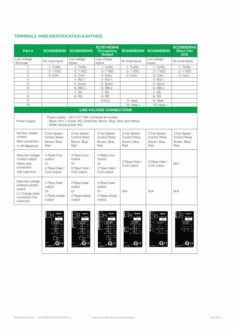
TERMINALS, WIRE IDENTIFICATION & RATINGS
Part # SC3500E5045 SC3504E5045SC3514E5045 Occupancy
OutputSC3400E5045 SC3404E5045
SC3300E5045 Slave Fan
UnitLow Voltage Terminals
No local inputsLow voltage inputs
Low voltage inputs
No local inputsLow voltage inputs
No local inputs
1 1- Tx/Rx 1- Tx/Rx 1- Tx/Rx 1- Tx/Rx 1- Tx/Rx 1- Tx/Rx2 2- 7 VDC 2- 7 VDC 2- 7 VDC 2- 7 VDC 2- 7 VDC 2- 7 VDC3 3- Com 3- Com 3- Com 3- Com 3- Com 3- Com4 4- RUI 1 4- RUI 1 4- RUI 15 5- Scom 5- Scom 5- Scom6 6- RBI 2 6- RBI 2 6- RBI 27 7- SS 7- SS 7- SS8 8- RS 8- RS 8- RS9 9-Occ 9- Heat - 9- Heat -10 10- Heat + 10- Heat +
LINE VOLTAGE CONNECTIONS
Power SupplyPower supply: - 90 to 277 VAC (universal all models)- Black Hot L1 Power VAC (Switches: Brown, Blue, Red, and Yellow)- White neutral power VAC
Fan line voltage contactWire connection½ HP Maximum
3 Fan Speed Control WiresBrown, Blue, Red
3 Fan Speed Control WiresBrown, Blue, Red
3 Fan Speed Control WiresBrown, Blue, Red
3 Fan Speed Control WiresBrown, Blue, Red
3 Fan Speed Control WiresBrown, Blue, Red
3 Fan Speed Control WiresBrown, Blue, Red
Valve line voltage contact outputYellow wire connection10A maximum
4 Pipes Cool outputOr2 Pipes Heat / Cool output
4 Pipes Cool outputOr2 Pipes Heat / Cool output
4 Pipes Cool outputOr2 Pipes Heat / Cool output
2 Pipes Heat / Cool output
2 Pipes Heat / Cool output
N/A
Valve line voltage isolated contact output2 x Orange wires connection10A maximum
4 Pipes Heat outputOr2 Pipes reheat output
4 Pipes Heat outputOr2 Pipes reheat output
4 Pipes Heat outputOr2 Pipes reheat output
N/A N/A N/A
Schneider Electric | II-SC3000-A4.EN.07.2016.v3 www.schneider-electric.com/buildings July 2016
8
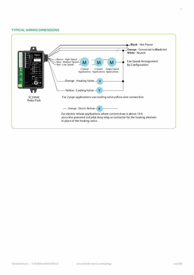
TYPICAL WIRING DIMENSIONS
SC3504ERelay Pack
Black - Hot Power
Orange - Connected to Black-HotWhite - Neutral
Brown - High SpeedBlue - Medium SpeedRed - Low Speed M
3 SpeedApplications
2 SpeedApplications
Single S peedApplications
For 2 pipe applications use cooling valve yellow wire connection
Fan Speed ArrangementBy Con�gurationM
Orange - Heating Valve
Yellow - Cooling Valve
V
V
M
Orange - Electric Reheat RFor electric reheat applications where current draw is above 10 Ause a line powered coil pilot duty relay or contactor for the heating elementin place of the heating valve.
Schneider Electric | II-SC3000-A4.EN.07.2016.v3 www.schneider-electric.com/buildings July 2016
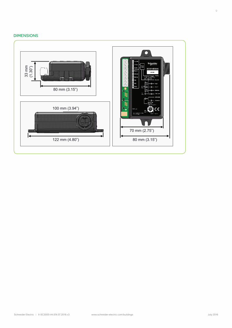
9
100 mm (3.94”)
80 mm (3.15”)
122 mm (4.80”) 80 mm (3.15”)
70 mm (2.75”)
33 m
m(1
.30”
) DIMENSIONS