Embed Size (px)
Citation preview

SC125U Installation Guide SOLARTECHNOLO
GY
125kW Photovoltaic, Grid-TiedString Inverter
Sunny Central SC125U
Installation Guide
i

SC125U Installation Guide
ii
SC125U Installation Guide
Copyright © 2003 SMA America, Inc. All rights reserved.
All rights reserved. No part of this document may be reproduced, stored in a retrievalsystem, or transmitted, in any form or by any means, electronic, mechanical,photographic, magnetic, or otherwise, without the prior written permission of SMAAmerica, Inc.
SMA America makes no representations, express or implied, with respect to thisdocumentation or any of the equipment and/or software it may describe, including (withno limitation) any implied warranties of utility, merchantability, or fitness for any particularpurpose. All such warranties are expressly disclaimed. Neither SMA America nor itsdistributors or dealers shall be liable for any indirect, incidental, or consequential damagesunder any circumstances.
(The exclusion of implied warranties may not apply in all cases under some statutes, andthus the above exclusion may not apply.)
Specifications are subject to change without notice. Every attempt has been made tomake this document complete, accurate, and up-to-date. Readers are cautioned,however, that SMA America reserves the right to make changes without notice and shallnot be responsible for any damages, including indirect, incidental or consequentialdamages, caused by reliance on the material presented, including, but not limited to,omissions, typographical errors, arithmetical errors, or listing errors in the contentmaterial.
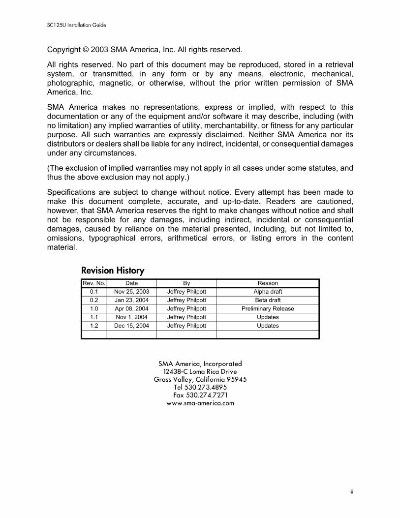
SMA America, Incorporated12438-C Loma Rica Drive
Grass Valley, California 95945Tel 530.273.4895Fax 530.274.7271
www.sma-america.com
Revision HistoryRev. No. Date By Reason
0.1 Nov 25, 2003 Jeffrey Philpott Alpha draft0.2 Jan 23, 2004 Jeffrey Philpott Beta draft1.0 Apr 08, 2004 Jeffrey Philpott Preliminary Release1.1 Nov 1, 2004 Jeffrey Philpott Updates1.2 Dec 15, 2004 Jeffrey Philpott Updates
iii

SC125U Installation Guide
IMPORTANT SAFETY INSTRUCTIONSSAVE THESE INSTRUCTIONS
This manual contains important instructions for the Sunny Central SC125U that must be followed during installation and maintenance of the inverter.
This document applies to SMA Sunny Central inverter models: SC125U-480, SC125U-240 and SC125U-208
The Sunny Central is designed and tested according to international safety requirements, but as with all electrical and electronic equipment, certain precautions must be observed when installing and/or operating the Sunny Central. To reduce the risk of personal injury and to ensure the safe installation and operation of the Sunny Central, you must carefully read and follow all instructions, cautions, and warnings in this Installation Guide.
Safety and Hazard Symbols
This symbol is used to call attention to important information that you must have when installing and/or operating the Sunny Central. Failure to read and follow instructions marked with this symbol could result in injury or death and/or damage to the equipment.
This symbol appears beside instructions and warnings that deal with dangerous voltages that can injure or kill people who come in contact with them.
This symbol appears beside instructions and cautions that deal with equipment components that can be damaged by static electricity.
Cautions and Warnings
WARNING: A Warning describes a hazard to personnel. It calls attention to a procedure or practice, which, if not correctly performed or adhered to, could result in personal injury.
CAUTION: A Caution describes a hazard to equipment. It calls attention to an operating procedure or practice, which, if not correctly performed or adhered to, could result in damage to or destruction of part or all of the SMA equipment and/or other equipment connected to the SMA equipment.
Warnings and Cautions may also be accompanied by one or more of the safety and hazard symbols described above to indicate the type of hazard described therein.
Other Symbols
This symbol accompanies notes that call attention to supplementary information that you should know and use to ensure optimal operation of the system.
iv

SC125U Installation Guide
Warranty
All Sunny Central inverters sold in the USA have a five-year warranty, as indicated on the warranty card included in the Sunny Central shipping container. For warranty coverage, or if you have questions about the Sunny Central warranty, contact SMA America at the address, telephone number, or Web site listed on page iii (to send E-mail, see the Contact section of the SMA America Web site: www.sma-america.com).
All electrical installation must be done in accordance with the local and National Electrical Code ANSI/NFPA 70.
The Sunny Central contains no user-serviceable parts. Always contact an SMA authorized Service Center for repairs and maintenance.
Before installing or using the Sunny Central, read all of the instructions, cautions, and warnings on the Sunny Central, the PV array, and in this Installation Guide.
Before connecting the Sunny Central to the electrical utility grid, contact the local utility company. This connection must be made only by qualified personnel.
PV arrays produce electrical energy when exposed to light and thus can create an electrical shock hazard. Wiring of the PV-arrays should only be performed by qualified personnel.
v

SC125U Installation Guide
vi

SC125U Installation Guide
1 IntroductionSystem Overview. . . . . . . . . . . . . . . . . . . . . . . . . . . . . . . . 1-1Interconnection Code Compliance. . . . . . . . . . . . . . . . . . . . 1-5Specifications . . . . . . . . . . . . . . . . . . . . . . . . . . . . . . . . . . 1-7
2 SafetySafety Features . . . . . . . . . . . . . . . . . . . . . . . . . . . . . . . . . 2-9
3 InstallationInstallation . . . . . . . . . . . . . . . . . . . . . . . . . . . . . . . . . . . 3-15Installation Procedure. . . . . . . . . . . . . . . . . . . . . . . . . . . . 3-22Commissioning . . . . . . . . . . . . . . . . . . . . . . . . . . . . . . . . 3-27
4 User InterfaceThe Sunny Central Control . . . . . . . . . . . . . . . . . . . . . . . . 4-31
5 Inverter OperationSystem Operation . . . . . . . . . . . . . . . . . . . . . . . . . . . . . . 5-37
6 TroubleshootingError Messages . . . . . . . . . . . . . . . . . . . . . . . . . . . . . . . . 6-41
i

SC125U Installation
ii

SC125U Installation Guide Introduction
Section 1:Introduction
System Overview
General
The SC125U is the collaborative effort between SMA America and SMA Regelsysteme. Our goal was to develop the highest quality, most durable and advanced grid-tied inverter in the photovoltaic (PV) industry. The same PV expertise found in over 250,000 fielded Sunny Boy inverters is integrated in the SC125U, only on a larger scale. Here is a brief list of benefits you will find in the SC125U:
• Isolation transformer is integrated within the inverter enclosure resulting in significantly higher daily power production.
• Sunny Central Control Plus advanced data-acquisition and control system included. (Also compatible with all other SMA communication products)
• FCC-A noise-emission compliance and certification, a Federal requirement for all US installations
• Rugged outdoor stainless-steel and aluminum enclosure• Hermetically sealed electronics compartment, temperature regulated with a robust air-to-
air heat exchanger• Temperature-regulated, energy-efficient cooling system• Advanced Maximum Peak Power Tracker (MPPT) algorithm• Alternate models available for interconnection to 480, 240 or 208 VAC utility voltages
Inverter Description
The SC125U is a DC-AC, unity power factor current-source power converter for photovoltaic power sources. DC PV power is converted to AC utility grade power through a single-stage, high-frequency, pulse-width-modulated (PWM) IGBT bridge. The DC and AC power is heavily filtered to provide safe, high-fidelity, low EMI/EMC emission power to the AC utility system.
Anti-islanding Protection
Islanding is a condition that can occur if the utility grid is disconnected while the SC125U is operating and the remaining load is resonant at 60 Hz and matches the output of the SC125U perfectly. This condition is highly unlikely and has never been witnessed outside a controlled laboratory. Nevertheless, the SC125U incorporates an advanced active islanding protection algorithm to insure that the system will not export power into a balanced 60Hz resonant load while the utility is disconnected. The SC125U periodically injects both leading and lagging VAR current into the utility grid. This method has been proven by Underwriters Laboratories to effectively destabilize a balanced island condition.
1
System Overview SC125U Installation
AC Voltage Configuration
The SC125U comes from SMA pre-configured for either 480, 240 or 208 VAC utility interface. All utility protection tests required by UL1741 have been performed by SMA prior to shipping.
AC Interface (Optional)
If the SC125U was ordered without an internal AC disconnect switch, utility wiring will be landed on stud-type terminal blocks within the user interface enclosure. Otherwise, wiring from the utility point of interconnection is landed directly onto the AC disconnect switch within the user interface enclosure. Internal to the AC disconnect switch is a thermal-magnetic molded-case circuit breaker. This is included to protect the inverter from faults originating on the utility distribution system. The AC switch is used to disable and isolate the SC125U from utility power during maintenance or repair.
DC Interface
PV array wiring is connected to DC buss bars located within the user interface enclosure. The buss bars feed directly to a load-break rated DC disconnect switch. The DC disconnect switch is used to isolate the PV array output from the inverter power electronics during service operations and in emergency situations.
GFDI Description
In the event of a ground fault from the PV array, the fault current will trip a breaker located in the user interface enclosure. Connected to the breaker are two contact switches. The first contact signals the controller that a ground fault has occurred, which executes a safe and orderly shut-down of the SC125U. The second contact interrupts coil holding current for the main AC contactor to insure the system is isolated from the AC utility system. The fault is then displayed on the user interface. Once the PV ground fault has been corrected and the GFDI breaker reset, the SC125U resumes normal operation.
Sunny Central Control Description
Incorporated into the SC125U control system is the Sunny Central Controller advanced data acquisition system (DAS). The SCC is the primary user interface for the SC125U. The menu driven user interface is navigated via a push-button keypad. The operator may view inverter status, operating parameters, and historical operating data on the LCD screen. Adjustable operational parameters are protected with a user password.
Remote Access Options
A variety of communication options are available to connect multiple SC125U's together, or combine other SMA products on the same communication buss. For customers desiring remote access to the SC125U, various modems, Ethernet and wireless options are also available for the Sunny Central Control (SCC). Local access to the SCC is a simple wire connection between
2

SC125U Installation Guide Introduction
a PC and the SCC. The Sunny Data Control software and a MS Windows PC are necessary to communicate with the SCC from local or remote locations. Sunny Data Control software is available free-of-charge on the SMA-America web site.
Figure 1-1 Sunny Central System Block Diagram
3

System Overview SC125U Installation
Sunny Central Control Display and Keypad
The Sunny Central Control (SCC) is the primary user interface for the Sunny Central. Through it, different operating states can be selected, system parameters can be set and operational data can be displayed.
For customers desiring remote access to the SC125U, various modems, Ethernet and wireless options are also available for the SCC. Local access to the SCC is a simple wire connection between a PC and the SCC. The Sunny Data Control program and a MS Windows PC are necessary to communicate with the SCC from local or remote locations. Sunny Data Control is available free-of-charge on the SMA-America web site.
Start/Stop Switch
The Start/Stop switch is the primary control switch for turning the Sunny Central on and off. When starting the inverter with this switch, the inverter conducts a series of self-tests and begins automatic operation. Using this switch to turn off the inverter during operation will cause the inverter to execute a safe and orderly shut down. The SC125U will remain inoperable until the switch is returned to the on position.
Circuit Breakers: AC, DC, Control Power, GFDI
Circuit breakers are provided in the Control cabinet to protect the inverter from external system faults.
DC Disconnect
The DC disconnect is a lockable rotary handled switch that is used to isolate the inverter from the PV array.
[ SUNNY CENTRAL][ CONTROL ]Time : 17:11.36Date :11/25/1998
4

SC125U Installation Guide Introduction
AC Disconnect
The AC disconnect is a lockable rotary handled switch that is used to isolate the inverter from the utility grid. Integrated into the AC disconnect is a thermal magnetic circuit breaker. Operating the AC disconnect also operates this circuit breaker. The AC disconnect is also used to reset the circuit breaker in the event of an AC over-current fault.
Interconnection Code ComplianceThe Sunny Central SC125U has been tested and listed by Underwriters Laboratories to meet the requirements of UL1741 Static Inverters and Charge Controllers for use in Photovoltaic Power Systems and UL1998 Software in Programmable Components, as well as IEEE-929-2000 Recommended Practice for Utility Interface of Photovoltaic Systems and IEEE 519 Standard Practices and Requirements for Harmonic Control in Electrical Power Systems. The SC125U is also listed under UL1741 for Canadian UL.
UL1741 is the standard applied by Underwriters Laboratories to the SC125U to certify that it meets the requirements of the NEC and IEEE-929-2000. IEEE 929-2000 provides recommendations regarding the proper equipment and functionality necessary to ensure compatible operation when power generation is connected to the utility grid.
Note: Contact the local utility and/or the authority having jurisdictionprior to connecting the Sunny Central to the utility grid.
5

Interconnection Code Compliance SC125U Installation
Figure 1-2 Control Cabinet Main Components
Sunny CentralControl
Com-Port(DB-9)
Start/StopSwitch
PV/DCDisconnect
AC/UtilityDisconnect
CircuitBreakers
Upper Panel
Lower Panel
6

SC125U Installation Guide Introduction
Specifications
Inverter Technology True sine wave, current source, high frequency PWM
Nominal AC Power Output 125 kW (at 45°C)
Acceptable Utility Voltage Range 422 - 528 VAC (480 VAC nominal) SC125U-480212 - 264 VAC (240 VAC nominal) SC125U-240183 - 228 VAC (208 VAC nominal) SC125U-208
Acceptable Utility Frequency Range
59.3 - 60.5 Hz (60 Hz nominal)
Current THD < 3%
Power Factor Unity
AC Output Current Limit 150 AAC (480 VAC)300 AAC (240 VAC)350 AAC (208 VAC)
Max. AC Output Switch andCircuit Breaker Current(Optional)
200 AAC (480 VAC)400 AAC (240 VAC)600 AAC (208 VAC)
DC Input Voltage 275 - 600V DC
Peak Power Tracking Voltage 275 - 550V DC
PV Start Voltage 450V DC (adjustable)
Maximum DC Current 460A @ 275V DC
DC Input Switch Rating 800A AC
DC Voltage Ripple (P to P) < 3%
Peak Inverter Efficiency 95.7% (fans off)
Power Consumption 110 W Standby
Ambient Temperature -25°C to +50°C
Cooling Temperature controlled forced fan cooling with optional sealed heat exchanger
Enclosure Bridge NEMA 4Main enclosure NEMA 3R, powder coated, stainless steel and aluminum
Table 1: Sunny Central SC125U Specifications
7
Specifications SC125U Installation
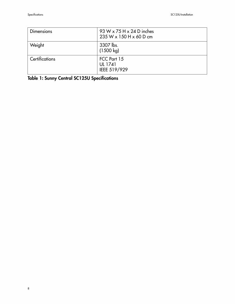
Dimensions 93 W x 75 H x 24 D inches235 W x 150 H x 60 D cm
Weight 3307 lbs.(1500 kg)
Certifications FCC Part 15UL 1741IEEE 519/929
Table 1: Sunny Central SC125U Specifications
8
SC125U Installation Guide Safety
Section 2:Safety
Safety Features
WARNING:The SC125U enclosure houses exposed high voltage con-ductors. The Inverter and Magnetics cabinet doors should thereforeremain locked at all times. Only qualified service personnel shouldenter the SC125U cabinets. These instructions are meant for use byqualified personnel only. To minimize the risk of electric shock, do notperform any servicing other than that specified in the operating in-structions unless you are qualified to do so. Do not open the cabinetdoors if there is extreme moisture present (rain or heavy dew).
WARNING: The user interface enclosure is not equipped with a lock forsafety reasons, therefore the Sunny Central must be installed in a securearea to prevent unauthorized personnel from accessing the controls tothe inverter.
Start/Stop Switch
The Start/Stop switch is the main control switch for the Sunny Central. Turning this switch to the “ON” position activates the SC125U. Turning the switch to the “OFF” position deactivates the SC125U. When the Start/Stop switch is used for deactivation, the SC125U performs a controlled shut down of the system. This nonlockable switch is located in the Control cabinet of the SC125U. The door to the Control cabinet remains unlocked during normal operation. This provides the user access to the main controls if it becomes necessary to deactivate the system.
AC/DC Disconnects
Both the AC (optional) and DC loadbreak disconnect switches are equipped with lockout hasps to help ensure personnel safety. The disconnects can be locked in either the On or Off position. Each switch handle also provides an interlock so that the main panel cannot be removed unless both switches are in the Off position. These switches must remain in the On position during normal operation and should not be used for turning the system Off. The AC and DC disconnects should only be used to isolate the main cabinets of the inverter for required maintenance or other service related tasks. Shutting down the SC125U should be done with the Start/Stop switch prior to opening the AC and DC disconnect switches.
Cabinet Door Locks and Safety Switches
The inverter and magnetics cabinets of the SC125U are key locked individually. Each door is equipped with and exterior locking handle that has a hasp for a padlock. This ensures that although the user may have a key to the handle itself, there is the provision for service
9
Safety Features SC125U Installation
personnel to add their own lock to prevent unauthorized personnel from accessing the internal components of the SC125U. Additionally, each door is equipped with a door interlock safety switch so that if the either door is opened while the SC125U is operating, the system will shut down immediately.
CAUTION: The SC125U will restart automatically once the doors aresecured if the system was caused to shut down because of the doorinterlock safety switches.
PV Ground Fault Detection and Interruption
The Sunny Central is equipped with a ground fault detection device. This device is a 3-pole, 10A circuit breaker located in the Control cabinet. Also ganged to this breaker is a 2-pole switch used to switch the power electronics into standby and signal the Sunny Central Control that a ground fault has been detected. If a ground fault current greater than 10A is detected, the SC125U will shut down and display the fault condition on the display of the Sunny Central Control. Once the ground fault is located and corrected, the GFDI will need to be manually reset. Once the GFDI is reset, the SC125U will automatically clear the fault condition and return to normal operation.
Fault/Error Reporting
All fault conditions or system errors are reported to the user on the Sunny Central Control. The Sunny Central Control also stores all faults, warnings and events in a historical log which is viewable by the user. Detailed descriptions of the fault and error codes are provided in a later section of this manual.
Voltage and Frequency Monitoring
The SC125U monitors both the voltage and frequency of the utility system. If either the voltage or frequency of the system exceeds the limits dictated by UL1741, the SC125U will shut down and report the appropriate fault on the Sunny Central Control. The default safety parameters were chosen based upon the requirements of both IEEE-929 and UL 1741. The safety parameters are shown in Table 1.
10

SC125U Installation Guide Safety
Anti-Islanding Protection
Islanding is a condition that can occur if the utility grid is disconnected while the SC125U is operating and the remaining load is resonant at 60 Hz and matches the output of the SC125U perfectly. This condition is highly unlikely and has never been witnessed outside of a controlled laboratory. Nevertheless, the SC125U incorporates an advanced active islanding protection algorithm to insure that the system will not export power in to a balanced 60Hz resonant load while the utility is disconnected. The SC125U periodically injects both leading and lagging VAR current into the utility grid. This method has been proven by Underwriters Laboratories to effectively destabilize and disconnect from a balanced island condition.
Isolation ProcedureThe following procedure should be used to deactivate and isolate the SC125U from both AC and DC power:
1. Turn the Start/Stop switch to the Off or “0” position
2. Turn the DC disconnect switch to the Off position
3. Turn the AC disconnect switch to the Off position
4. Install lockout devices on the DC and AC disconnect switches
Utility ProtectionFault Condition(% of Nominal)
ReactionTime
VAC < 50% 6 Cycles
50% > VAC > 88% 120 Cycles
88% > VAC > 106% Normal
106% > VAC > 137% 120 Cycles
VAC > 137% 2 Cycles
f < rated -0.7 6 Cycles
f > rated +0.5 6 Cycles
Table 1: Safety Parameters Required by UL1741-1999
11

Safety Features SC125U Installation
WARNING:After disconnecting the SC125U from AC and DC power,the DC input terminals of the PV array will remain energized if thearray is still energized, as will the AC output terminals. Therefore,care should be taken when working in the control cabinet. Wait 5minutes after switching off the AC and DC disconnect switches beforeproceeding to allow time for any stored potential in the SC125U tocompletely discharge. Any work performed in the control cabinetshould be completed only by qualified personnel.
Integrated Isolation Transformer
Because NEC 690.41 requires the PV array be electrically grounded, galvanic isolation between PV DC and utility AC power systems is necessary. The Sunny Central accomplishes this with a high-efficiency WYE-WYE isolation transformer for interconnection with common, 3-phase 4-wire utility services. The transformer is mounted within the main enclosure to allow the inverter to control and disconnect it when there is no PV array power. (Other large PV inverters require that an isolation transformer be specified and purchased, but the Sunny Central has one included in the control system.)
The advanced magnetics used in the internal isolation transformer are carefully matched to the characteristics of the inverter. The AC contactor disconnects the internal transformer when the PV system is not providing energy and this eliminates the energy losses associated with a transformer that is always connected to the utility grid. With an internal transformer, there are no code questions raised by inspectors as to whether the circuits between the inverter and the external transformer need to be grounded. By enclosing the transformer in the inverter cabinet, extra weight and costs are saved by not requiring a separate housing and mounting system as would be required with an external transformer.
480, 240 and 208 utility voltage configurations are available.
12

SC125U Installation Guide Safety
Figure 2-1 Cabinet Door Interlocks and Main Components
Front
CabinetInterlockSwitches
Transformer
Filter
Inverter
13

Safety Features SC125U Installation
14

SC125U Installation Guide Installation
Section 3:Installation
Installation
CAUTION: All installation methods must be performed in accordance withthe National Electrical Code (NEC) ANSI/NFPA 70. All wiring connectedto the Sunny Central SC125U must be of size and type accepted by theNEC ANSI/NFPA 70 and all local codes. The minimum bending radius forlarge cabling must be observed as stated in the NEC.
WARNING:To prevent electrical shock or injury, all wiring and com-missioning procedures must be performed by qualified personnel.
Ventilation and Clearances
A minimum of 48” of clearance shall be maintained in front of the Inverter and Magnetics cabinet doors and in front of the Control cabinet door and 30” of clearance behind the enclosure. It is recommended that some space be maintained to the right of the enclosure.
Figure 3-1 Clearances for the SC125U Enclosure
15

Installation SC125U Installation
Foundation Considerations
The SC125U weighs approximately 3300 lbs. (1500 kg). The mounting surface must be level and strong enough to support the weight of the inverter. The inverter must be secured to the foundation per local building codes. Four mounting holes are located along the interior perimeter of the SC125U enclosure and accept up to 7/16” hardware. If the main wiring is entering the inverter through the bottom area, conduit will need to be added to the foundation.
Figure 3-2 Anchoring Footprint
Lifting and Moving
Due to the size and weight of the SC125U, it is recommended that it remain on the pallet it was shipped on until ready for installation.
CAUTION: Extra care must be used when moving the SC125U because theweight of the inverter is not evenly distributed within the enclosure. Themajority of the inverter’s weight is on the Magnetics cabinet end of theenclosure. Refer to Figure 3-4 and to the center of gravity (CG) markinglocations on the box.
Slots for moving the SC125U with a fork lift or palette jacks are shown in Figure 3-3. The center set of slots are to be used for moving the SC125U with a fork lift or a large palette jack. The outside sets of slots are to be used when moving the SC125U with a set of smaller palette jacks. Remember that the inverter weighs 3300 lbs. Make sure that your equipment is rated for this weight before attempting to move the inverter.
16

SC125U Installation Guide Installation
Figure 3-3 Lifting Points for the SC125U
Base Plates Removed
Small Palette Jack Small Palette Jack
Large Palette Jackor Fork Lift
17

Installation SC125U Installation
Figure 3-4 Center of Gravity
Front Side
54.50" 33.90"
16.18" 7.44"
40.75" 40.75"
30.43" 30.43"
CG CG
18

SC125U Installation Guide Installation
Dimensions
Figure 3-5 Front and Top Views
19

Installation SC125U Installation
Figure 3-6 Back and Bottom Views
20

SC125U Installation Guide Installation
Cabinet Door Locks
The Sunny Central is equipped with locking door handles. For safety reasons, the Control cabinet door does not lock in order to allow access to the AC and DC disconnect switches. The Inverter and Magnetic cabinets are both lockable and are equipped with a hasp for an additional padlock. Follow the instructions in Figure 3-7 to unlock the cabinet handles.
Figure 3-7 Cabinet Door Lock Operation
Wiring and Torque Specifications
The following tables show the required torque settings and acceptable wire sizes to be used when making connections to the SC125U.
Terminal Block or Bolt Torque Setting
AC Disconnect 180 in. lbs./15 ft. lbs
DC Compression Lugs 250 in. lbs./21 ft. lbs.
Ground 250 in. lbs./21 ft. lbs.
Table 1: Torque Requirements
Slide cover upand insert key
Turn the key andwhen the handle pops up,turn it to the side to open.
21

Installation Procedure SC125U Installation
Installation Procedure
Mounting the Inverter
• Drill or punch appropriate conduit knockouts. Be sure to avoid getting metal particles in-side the wiring area of the inverter
• Remove inverter base plates to expose fork lift slots
• Move the SC125U into place
• Mark mounting hole locations
• Move SC125U away for drilling holes
• Install appropriate anchors in concrete pad
• Move SC125U into place
• Secure the SC125U to the foundation using 7/16” hardware
• Torque anchor bolts to specification
• Install conduit hardware
• Pull wires through conduit (if not already done) and into the bottom of the Control cabinet
Main Power Wire Connections
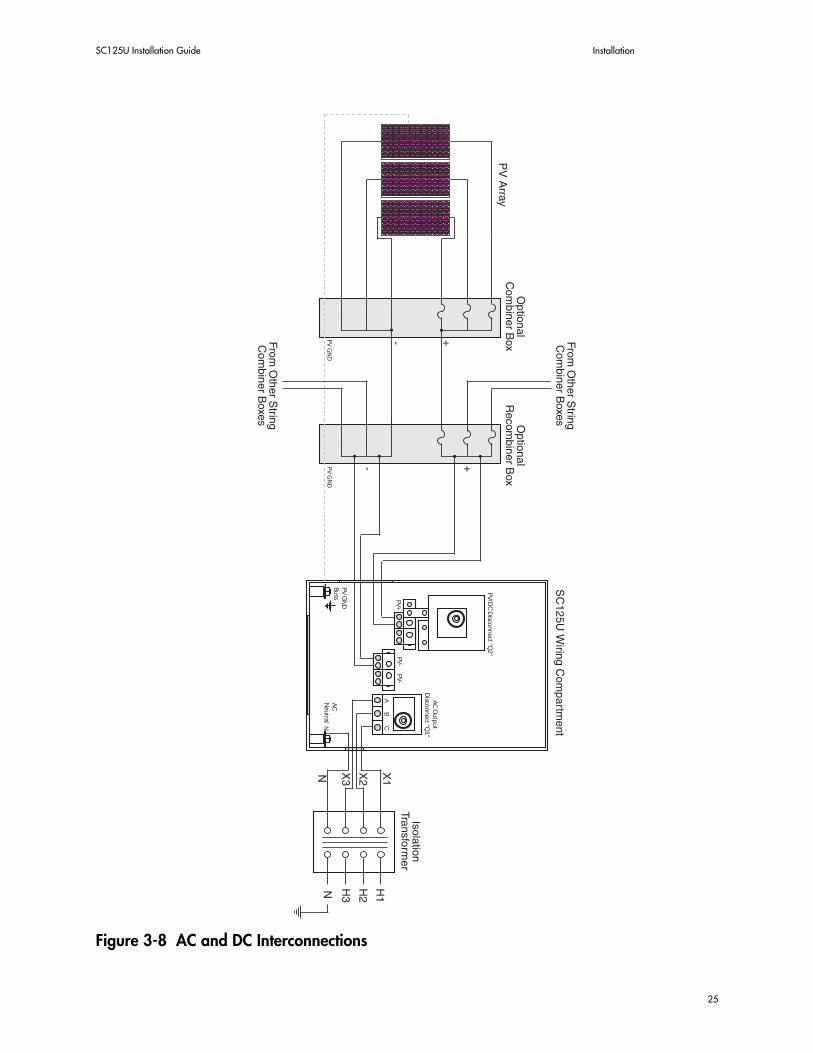
• Refer to Figure 3-8 for terminal locations
• Verify that all AC and DC disconnect switches are in the OFF position
• Connect the grounding-electrode conductor from the grounding system to the terminal marked “Grounding Electrode”
• Connect the equipment-grounding conductor(s) from the DC PV circuits to the appropriate terminals on the ground bus in the inverter
Termination Wire Range in AWG
AC Disconnect 1 x 300 MCM, 2 x 1/0 per pole
PV+ / PV- 2 x 4/0 per pole
Ground 1 X 300 MCM
Table 2: Wire Gauge Requirements
22

SC125U Installation Guide Installation
• Connect the equipment-grounding conductor(s) from the AC output circuits to the appropri-ate terminals on the ground bus in the inverter
• Connect the PV+ and PV- wires. Be sure that the PV array is not energized when making these connections
Note: Depending on your installation, The NEC may require that ratherlarge AC and DC current carrying conductors be used. Multiple, smallerparallel conductors may be used to reduce bending radius requirementsand ease installation. Refer to NEC for conductor sizing.
• Connect the AC Neutral phase conductor to the neutral output terminal.
Note: This terminal is isolated from ground in the inverter. Grounding ofthe AC output neutral conductor must be accomplished outside the inverter,usually at the service entrance equipment.
• Connect the three AC phase wires to terminals A, B and C. Be sure that the breaker is turned OFF at the sub-panel and to observe proper phasing when connecting these wires.
• Torque all wire terminations as required by the manufacturer’s recommendations
• Replace fork slot skirts
Note: The SC125U has auto phase detection capability. However, it is stillimportant to maintain proper phasing when making the AC connections.See Commissioning section for instructions on phase checking.
CAUTION: It is the responsibility of the installer to see to it that the inputand output circuits are isolated from the enclosure, if required by sections690.41 and 690.42 of the National Electrical Code ANSI/NFPA 70, andto assure that the system is properly grounded.
CAUTION: Sections 690.41 and 690.42 of the National Electrical Coderequire that the PV array be earth grounded. The DC negative conductorinput into the inverter is grounded internally in the inverter by the GFDIcircuit. Do not ground the negative PV conductor at any other place on theDC circuits. The chassis of the SC125U is also bonded to the PV groundbus bar.
CAUTION: The AC output circuit for the SC125U should be sized for themaximum continuous output current rating and in compliance with theNEC.
23

Installation Procedure SC125U Installation
WARNING:The PV array will produce high voltages when exposedto sunlight.
WARNING:To prevent electrical shock or other injury, verify that theAC and DC wires are not energized during installation.
24
SC125U Installation Guide Installation
Figure 3-8 AC and DC Interconnections
AC
Neu
tral
PV G
ND
Bu
ss
AC
Ou
tpu
tD
iscon
nect "Q
1"
PV+
PV-
PV-
AB
C
PV/D
C D
iscon
nect "Q
2"
N
25
Installation Procedure SC125U Installation
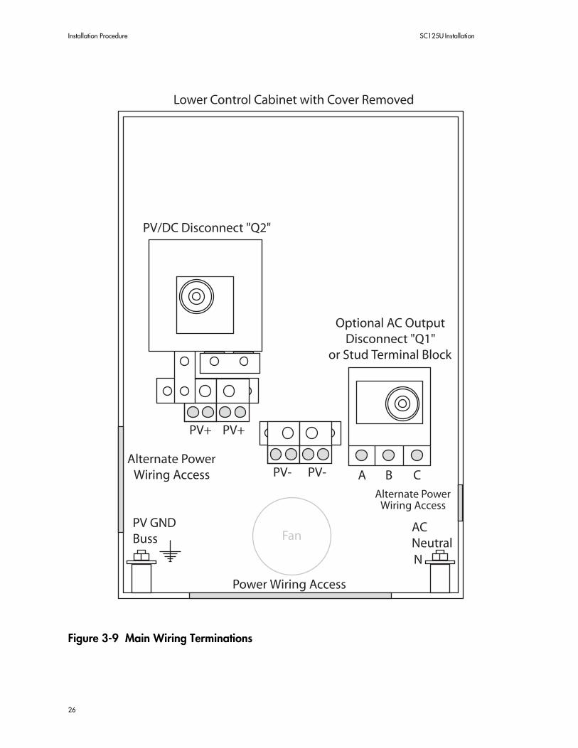
Figure 3-9 Main Wiring Terminations
26
SC125U Installation Guide Installation
Commissioning
Note:The following procedures must be performed by a qualified techni-cian. These procedures are intended to assure proper installation and op-eration of the SC125U. Do not continue if the results of any of the steps areincorrect or unclear.
Visual Inspection of the SC125U
• Insure that all AC and DC disconnect switches are in the OFF position
• Wait 15 minutes for all internal power supplies to discharge
• Inspect all large power cable and bus connections throughout the inverter to verify that they are tight
• Verify that all PV wires are connected with the proper polarity
• Verify that all PV wires are tightened to the proper torque specification
• Verify that the PV ground wire is connected to ground and is isolated from PV+, PV-
• Verify that the AC neutral wire is connected to the AC Neutral buss
• Verify that the AC phase wires are connected correctly
• Verify that all AC phase wires are tightened to the proper torque specification
• Inspect the interior of the wiring cabinet and insure that it is free of any tools, foreign objects or debris
• Leave lower panel of the Control cabinet open for measurement purposes
CAUTION: The lower cabinet will contain exposed energized conductorsand buss bars. Use extreme caution when taking measurements during thecommissioning process.
• Inspect the interior of the Inverter and Magnetics cabinets to insure that they a free of any tools, foreign objects or debris
• Verify that the doors to the Inverter and Magnetics cabinets are closed securely and latched
• Insure that the area around the SC125U is clear of any tools, foreign objects or debris
27

Commissioning SC125U Installation
Figure 3-10 Control Panel Main Components with Lower Cover Removed
Initial AC Voltage and Phasing Verification
• Turn the input breaker in the AC Sub-panel on
• Using an adjustable wrench on the square shaft of the AC disconnect switch, carefully turn the AC/Utility disconnect switch to the ON position
• Open the upper panel of the Control cabinet by removing the screws and pulling the panel down. (See Figure 3-10)
• Press the small, white, square switch on the relay located in the lower left corner (see Figure 3.10)
• When the fan in the blower housing comes on, verify the direction of air flow through the rear upper vent of the blower housing. Check the direction of air flow by holding a piece of paper up to the vent. The air should suck the paper up against the air intake grill with a
28
SC125U Installation Guide Installation
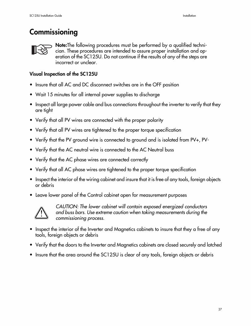
good amount of force. (If the air blows the paper away or if the paper falls away from the grill, shut off all AC disconnects and reverse any two AC wires at the AC disconnect)
• After the wires have been reversed, repeat the above step to insure proper phasing
• After verification process is complete, using an adjustable wrench on the square shaft, turn the AC disconnect switch to the OFF position
Figure 3-11 Location of Fan Relay and Air Intake Grill
Initial DC Voltage and Polarity Verification
Note:The measuring of the DC input voltage must be performed when thePV array is energized. Verify that the array is exposed to direct sunlight.
• With the DC disconnect switch still in the OFF position, carefully measure VDC from the PV+ at the disconnect and PV-
Air IntakeGrill
AC/UtilityDisconnect
Hold Sheet ofPaper Here
Blower onBack ofSC125U
Fan Relay
Panel Screws (2)
29

Commissioning SC125U Installation
• Verify that the PV voltage is positive and within the range specified on the unit rating label
• Using a adjustable wrench on the shaft of the DC disconnect switch, rotate the switch to the ON position. Carefully measure VDC across PV+ and PV- and verify that the voltage is pos-itive and within the range specified on the unit rating label
• After the testing process is complete, verify that the AC and DC disconnect switches are in the OFF position, then replace all safety shields and the lower panel of the Control cabinet
Note:To replace the lower panel of the Control cabinet, both the shafts andswitches of the AC and DC disconnects must be in the OFF position.
Initial Startup
• Turn AC/Utility Disconnect switch to the ON position
• Turn the PV/DC Disconnect switch to the ON position
• Turn the Start/Stop switch to the ON position
• Verify that the display indicates that the inverter is performing self tests
• After self tests are complete, the inverter will begin operation and the status of the inverter will be indicated on the Sunny Central Control.
30

SC125U Installation Guide User Interface
Section 4:User Interface
The Sunny Central Control
Overview
The Sunny Central Control user interface is made up of a four-line display with 16 characters per line and four function keys. The LCD display shows system status, historical data, parameter values and fault messages. The four keys are used for navigation, changing parameter values and changing operating states. The key functionality is described in the figure and table below.
Figure 4-1 User Interface
Key Function
ESC Cancel, Answer NO, Enter Main Menu, Return to Auto Mode
UP Arrow Scroll Upward, Increase Value
DOWN Arrow Scroll Downward, Decrease Value
ENTER Select Function, Select Value, Confirm Changes, Answer YES
UP+DWN Arrows Return to Auto Mode
Table 1: Key Functionality
Central
31

The Sunny Central Control SC125U Installation
Operation
How Information is Displayed
Figure 4-2 Display Window
The multiple display lines of the Sunny Central Control menu are viewable 4 lines at a time. Using the arrow keys the display window is moved up or down to allow the user to navigate through the menu.
1. Display Line
2. Display Line
3. Display Line
4. Display Line
5. Display Line
6. Display Line
7. Display Line
8. Display Line
9. Display Line
10. Display Line
11. Display Line
12. Display Line
13. Display Line
14. Display Line
Additional linesabove the displaywindow are accessibleusing the [ ] key.
4 Lines of informationare viewable at a time.
Additional linesbelow the displaywindow are accessibleusing the [ ] key.
Display Window
32

SC125U Installation Guide User Interface
Additional Characters
Figure 4-3 Additional Display Characters
Arrows along the left edge of the display will indicate which display line is currently active. These arrows can be moved up and down the display using the UP and DOWN arrow keys. If the arrow is blinking, it is indicating that the active line is waiting for a response from the user. (ENTER to Confirm or ESC to Cancel)
Arrows in the lower right corner of the display indicate that there is information either above or below the display, or both, which is out of the current view. The additional display lines can be accessed using the UP and DOWN arrow keys.
Display Contrast
It is possible to adjust the contrast of the LCD display by holding the ESC key and then pressing the UP arrow to increase the contrast, or the DOWN arrow to decrease the contrast.
1. Display Line
2. Display Line
3. Display Line
4. Display Line
5. Display Line
6. Display Line
7. Display Line
8. Display Line
9. Display Line
10. Display Line
11. Display Line
12. Display Line
13. Display Line
14. Display Line
Steady Arrow:Indicates whichdisplay line iscurrently active
Blinking Arrow:Indicates an entrywaiting forconfirmation
UP+DOWN arrowsindicate additionallines above and belowthe display
UP arrow indicatesadditional lines areabove the display
DOWN arrow indicatesadditional lines arebelow the display
33

The Sunny Central Control SC125U Installation
Auto Mode
When the SC125U is powered up it will automatically perform self tests as well as PV and grid tests. If all start up parameters are met, it will start. During this process the display message will be “SMA” repeated on each display line.
Once the system has started, the display will enter Auto Mode. Auto Mode is a series of 4 screens that the Sunny Central Control automatically scrolls through that show the current operating status of the inverter. Each screen is displayed for 2 to 3 seconds.
For an example of the start up and Auto Mode screens refer to Figure 5-4. Figure 5-4 also includes a sample error message. If while initializing the SC25U detects a fault of some sort it will report in on the display as shown.
When in Auto Mode, each of the 4 screens can be accessed manually by using the UP or DOWN arrow keys.
To exit Auto Mode and enter the main menu of the Sunny Central Control, press the ESC key. Once in the main menu, you can navigate to the different parameters using the UP and DOWN arrow keys. If the control is left idle for 60 seconds it will return to Auto Mode automatically.
Editing Mode
To make any changes to system parameters, you must enter the Editing Mode on the Sunny Central Control. Editing Mode can only be entered when the active line on the display is editable. To enter the Editing Mode, navigate to the display line you wish to edit and press the ENTER key.
After pressing the ENTER key the current value for the parameter selected will begin to blink. Once blinking, the value can be changed using the UP or DOWN arrow keys.
When making a change with an arrow key, it is important to note that the longer the key is held, the more rapidly the value will change. For example, if you wish to make a minor change of +3 units, you would press the UP arrow key three times. If, on the other hand, you wanted to make a change of +300 units, you would press and hold the UP arrow key causing the value to increase rapidly. Once near the desired value, release the UP arrow key and wait for the parameter to begin blinking again. Once blinking, select the final value slowly by pressing the UP arrow key (or the DOWN arrow key) repeatedly until the desired value is reached.
Once the desired value is reached, press the ENTER key to confirm the entry or the ESC key to cancel. If neither key is pressed within 60 seconds the parameter will automatically revert to its previous value.
34

SC125U Installation Guide User Interface
Figure 4-4 Sunny Central Control Display Screens
Navigation Example
The following diagram provides a sample of how navigating to a particular menu item can be accomplished using the Sunny Central Control.
Auto Mode Screens
[ SUNNY CENTRAL ][ CONTROL ]Time: 14:23.35Date: 26.12.03
Status StopPac 0.00kWE_Today 0.0kWhE_Total 0.0kWh
Screen 1
Screen 2
Status StopVac1 ---- VVac2 ---- VVac3 ---- V
Status Stopfac 0.00 HzVpv 0.00 VIac-WRB 0.00 A
Screen 3
Screen 4
SMA SMA SMA SMASMA SMA SMA SMA
SMA SMA SMA SMASMA SMA SMA SMA
Startup screen shown during self test
[ Failure ]
GFDI
Sample Error Message
35

The Sunny Central Control SC125U Installation
Figure 4-5 Sample of Sunny Central Control Navigation
[ SUNNY CENTRAL ][ CONTROL ]Time: 14:23.35Date: 26.12.03
[ Main Menu ]Operating DataSpot ValuesLong-Term Data
[ Spot Meas.Val. ]PVgen/Inv.Brid.GridOther
[ Grid ]Pac.......--.--kWfac
[ Main Menu ]Operating DataSpot ValuesLong-Term Data
[ Spot Meas.Val. ]PVgen/Inv.Brid.GridOther
Press: ESC
Press:
Press: Enter
Press:
Press: Enter
[ Spot Meas.Val. ]PVgen/Inv.Brid.GridOther
Press: Esc
While the controller is in Auto Mode,press the ESC key to enter the Main Menu
Once in the Main Menu, scroll downone line to Spot Values by pressingthe down arrow key
You can then choose Spot Values bypressing the Enter key
Once in the Spot Values Menu, scrolldown one line by pressing the downarrow key
Once the Grid line is active, chooseit by pressing the Enter key
The Grid menu display
Once you've observed the values,press the ESC key to go back to theprevious menu where you can makeanother selection or proceed back upthe menus until reaching the Main menuonce again
36

SC125U Installation Guide Inverter Operation
Section 5:Inverter Operation
System Operation
Overview
The Sunny Central SC125U is designed to operate automatically. All self test, fault detection, operational and start/stop functionality are performed by the SC125U without user interaction. The primary user interface for the SC125U is the Sunny Central Control (SCC). The SCC allows users to view and set system parameters as well as view data stored in the system’s memory.
The Sunny Central Control (SCC)
The SCC is the primary user interface for the SC125U. It consists of a 4-line LCD display and 4 control keys.
Figure 5-1 Front of Sunny Central Control
The Sunny Central Control’s primary groups of functions are as follows:
• User operation of the inverter
• Maximum power point tracking
• Display of current system values
• Changing inverter parameters
• Recording and long-term storage of system data
• Connection of optional external sensors
• Connection of optional remote metering devices
[ SUNNY CENTRAL][ CONTROL ]Time : 17:11.36Date :11/25/1998
37
System Operation SC125U Installation
Operating States
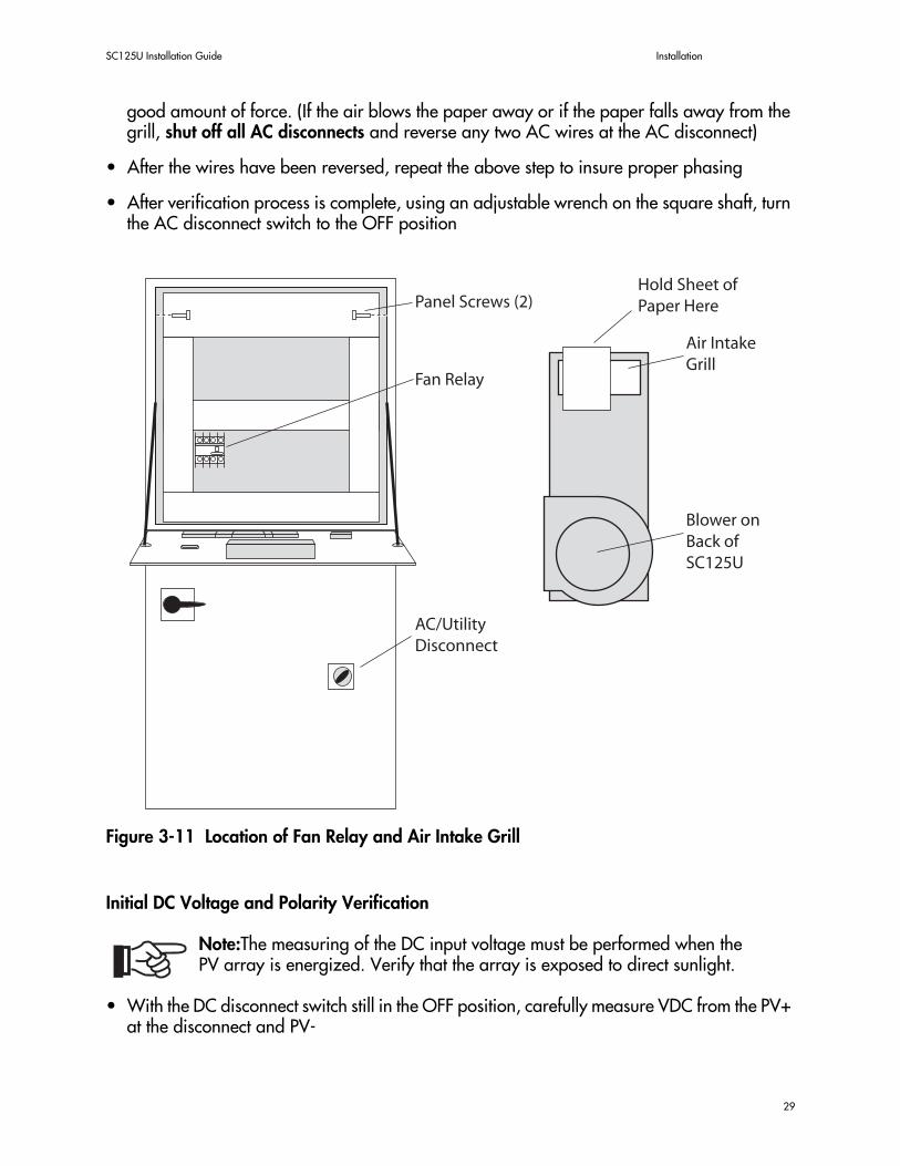
Figure 5-2 Operating States of the Sunny Central
The “Stop” State
The Sunny Central will remain in this state while the Start/Stop switch is in the Stop position.
The “Waiting” State
The Sunny Central will remain in the Waiting state as long as the PV array voltage is less than the value set for “VpvStart”. “Waiting” will be shown on the display.
The “Shut Down” State
The Shut Down state is entered anytime the SC125U engages in an orderly and safe shut down of the system. This state can be entered automatically if the voltage of the PV array drops below “VpvStart” (i.e. at night). The Shut Down state may also be entered manually by switching the main power switch on the SC125U to the Off position.
Waiting
Startup
Stop
Start andno Fault
Fault Confirmedor Fault Cleared
StopSwitch
StopSwitch
Pist < Pstopor Stop Switch
Vpv > Vstart
StartupComplete
Shutdown
From any State
MPPT
*Fault
*The system's exact behavior onfault will depend on the fault type.
38

SC125U Installation Guide Inverter Operation
The “Fault” State
Anytime the SC125U detects a fault in the system it will execute an orderly shut down of the system and then enter the Fault state. In the Fault state, the invert remains inactive and displays the type of fault encountered on the SCC display. The inverter will remain in this state until the fault is cleared. In some cases the inverter will need to be manually reset before it will resume operation.
Start Up
While in the Waiting state, if the PV array voltage rises above the parameter set for “VpvStart”, the inverter will wait for the amount of time set in the “TStart” parameter. Once the inverter has completed the wait-time set for “TStart” and provided that the PV array voltage has not dropped below the value set for “VpvStart” during that period, the inverter will automatically start and the message “Starting” will be shown on the display. If the PV voltage drops below “VpvStart” the “TStart” timer will reset and the inverter will return to the waiting state.
Maximum Power Point (MPP) / MPP Tracking (MPPT)
When operating in MPP mode, the SC125U tracks the array at the optimum power point to achieve maximum efficiency from the PV array. The inverter actively adjusts the voltage and current of the PV array while monitoring for changes in power.
The inverter begins by measuring the idle voltage of the PV array. Then the initial value for MPP Tracking is selected based upon the idle voltage multiplied by the value set for the “MppFactor” parameter. This assures that the inverter will begin tracking in the current MPP range of the PV array. (The initial MPP range that is selected may be predetermined by the value set for the “dVreference” parameter.)
After the idle voltage has been measured, the message on the display changes from “MPP Tracking” to “MPP”. If the MPP shifts at any time due to cell temperature or insolation, the MPP setpoint is automatically adjusted. The value of adjustment is determined by the “dVTrack” parameter in the time pattern “TcheckMpp”. Because this routine is repeated, the operating point is continuously optimized.
If the initial MPP setpoint selected is out of the range specified by the “dVreference” parameter, the inverter will apply a tracking algorithm. In this way the inverter is able to keep the system running at its optimum setpoint even during unfavorable operating conditions.
Constant Voltage Mode
In this mode the inverter will regulate the DC voltage to the setting of the “Vconst” parameter. During this operating state, “V_const” is shown on the display.
39

System Operation SC125U Installation
40

SC125U Installation Guide Troubleshooting
Section 6:Troubleshooting
Error MessagesWhenever the SC125U encounters a fault condition, it will take appropriate action and display the type of fault encountered on the Sunny Central Control. Use the following table as a guide to the error messages as well as the corrective action to take.
Error Message Cause(s) Corrective Action(s)
[ Failure 1 ]overtemperaturecabinet inverteror transformer
>The temperature in the inverter and/or the mag-netics cabinet is too high.> The heat exchanger is defective>Filters on magnetics cab-inet clogged>Heatsink
>Check that the thermocontacts in the sinusoidal filter are not tripped.>Clean filters>Call SMA(This error will reset automati-cally in the SCC when fault is cleared)
[ Failure 2 ]ser. com with
inverter bridge disturbed
>The (RS485) communi-cation between the inverter and the SCC has been interrupted
>Check communication cable>Check connections to SCC>Check communications module>Call SMA
[ Failure 4 ]internal failure ofinverter bridge
>This is a general error code for anything pertain-ing to the inverter bridge
>Check inverter bridge connec-tions>Call SMA
[ Failure 14 ]Release Signal
faulty
>The SCC is unable to release the inverter bridge
>Check the SCC release relay for proper operation>Inverter Bridge defective>Call SMA(This error will reset automati-cally in the SCC when fault is cleared)
[ Failure 15 ]heat sink fan fault
>Fan screen obstructed>Fan motor failure
>Verify that fan screen is clear>Reset fan motor protection switch manually>If failure persists, replace fan
Table 1: Error Messages and Troubleshooting
41

Error Messages SC125U Installation
Inverter Bridge Troubleshooting
The Sunny Central Control (SCC) has the ability to detect an array of error types. Each of these errors is stored in the “Faults” database within the SCC. In the case of the inverter bridge, all errors are displayed on the SCC as [ Failure 4 ]. A detailed description of the precise error can be displayed by navigating to “Operating Data”, then to “Faults”. In the Faults section you will see a log of the faults encountered by the SC125U beginning with the most recent. The following table contains descriptions of each of the error codes that the SCC will display for an inverter bridge type of error.
[ Failure 16 ]GFDI Tripped
>Current to ground greater than10A>Ground fault in array
>Locate and remove ground fault>Reset GFDI breaker after fault is cleared(This error will reset automati-cally in the SCC when fault is cleared)
[ Failure 17 ]DC CB tripped ordoor switch open
>DC circuit breaker open>Door not secured
>Reset DC circuit breaker>Secure all doors>Check interlock switch(This error will reset automati-cally in the SCC when fault is cleared)
[ Failure 18 ]Rest Signal faulty
>The SCC is unable to reset the inverter bridge(in case of a failure, etc.)
>Check SCC reset relay>Inverter Bridge defective>Contact SMA(This error will reset automati-cally in the SCC when fault is cleared)
Error Message Cause(s) Corrective Action(s)
Table 1: Error Messages and Troubleshooting
42