Embed Size (px)
Citation preview
S/C System Design Overview
Robert G. Melton
Department of Aerospace Engineering
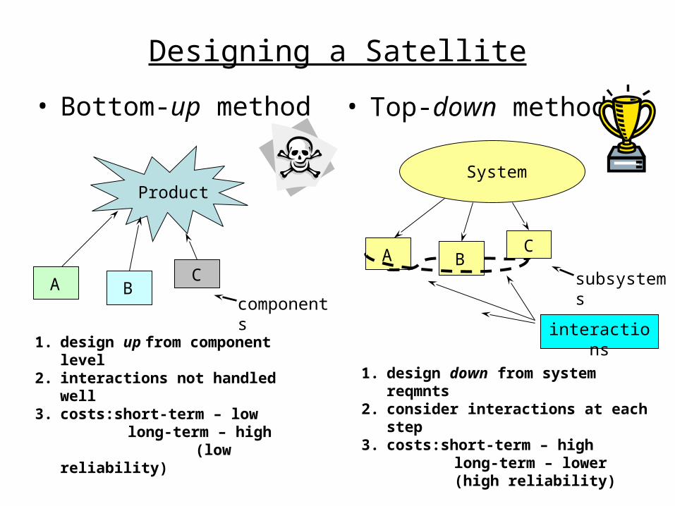
Designing a Satellite
• Bottom-up method • Top-down method
Product
A BC
components
1. design up from component level2. interactions not handled well3. costs:short-term – low
long-term – high (low reliability)
System
A B
interactions
1. design down from system reqmnts2. consider interactions at each step3. costs:short-term – high
long-term – lower(high reliability)
subsystems
C
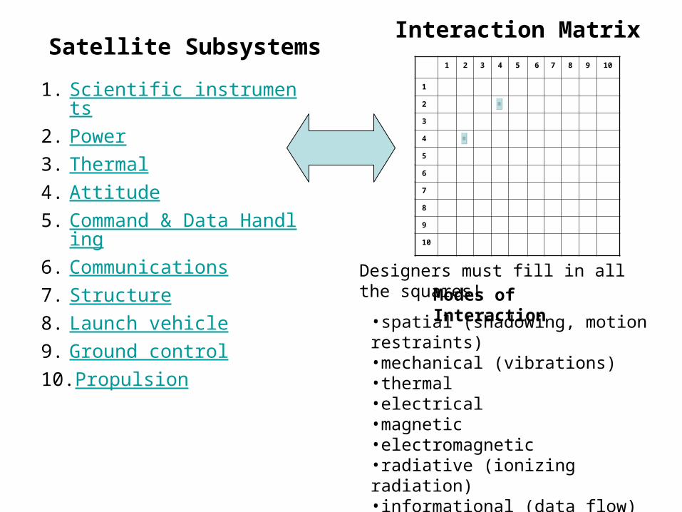
1. Scientific instruments2. Power3. Thermal4. Attitude5. Command & Data Handlin
g6. Communications7. Structure8. Launch vehicle9. Ground control10.Propulsion
Satellite SubsystemsInteraction Matrix
1 2 3 4 5 6 7 8 9 10
1
2
3
4
5
6
7
8
9
10
Designers must fill in all the squares!
Modes of Interaction
•spatial (shadowing, motion restraints)•mechanical (vibrations)•thermal•electrical•magnetic•electromagnetic•radiative (ionizing radiation)•informational (data flow)•biological (contamination)
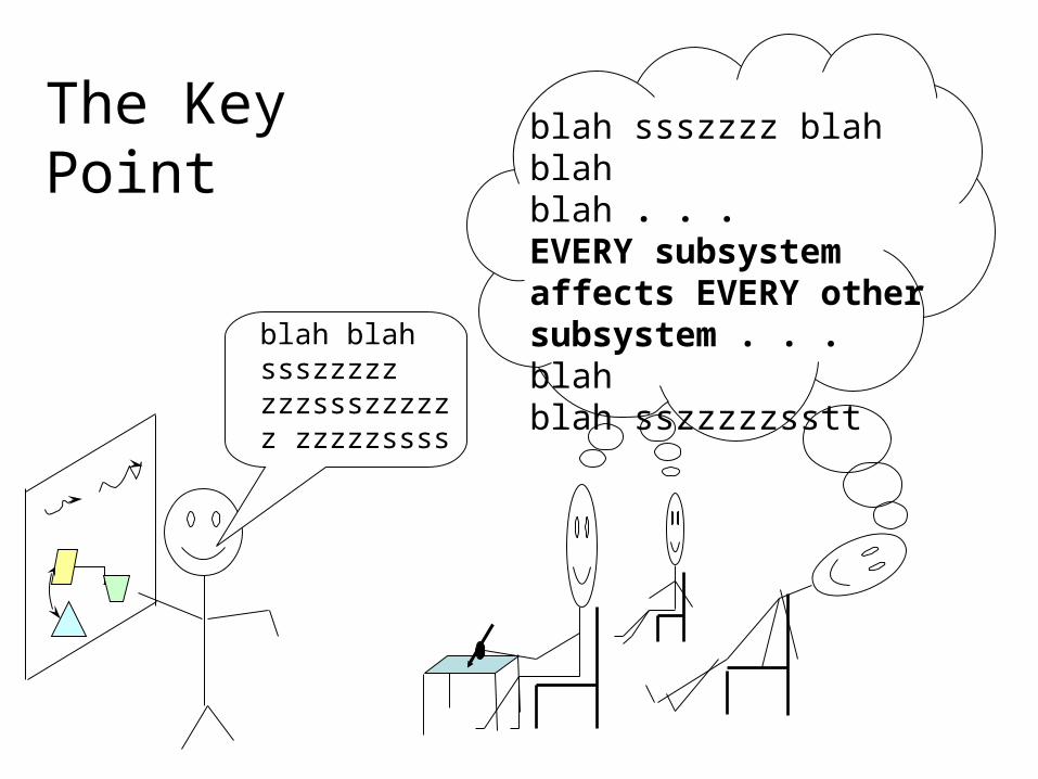
blah blah ssszzzzz zzzssszzzzzz zzzzzssss
blah ssszzzz blah blahblah . . . EVERY subsystem affects EVERY other subsystem . . . blahblah sszzzzzsstt
The Key Point
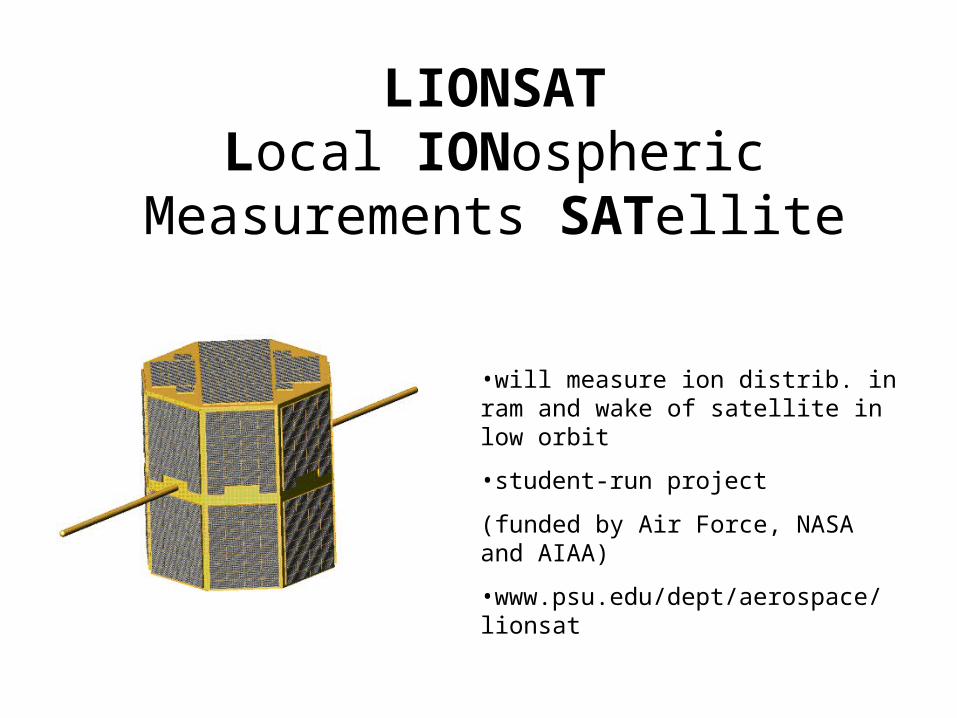
LIONSATLocal IONospheric Measurements
SATellite
•will measure ion distrib. in ram and wake of satellite in low orbit
•student-run project
(funded by Air Force, NASA and AIAA)
•www.psu.edu/dept/aerospace/lionsat
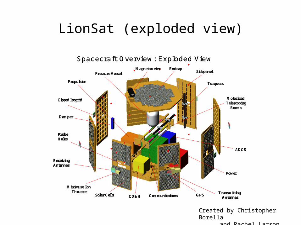
LionSat (exploded view)
Solar Cells
EndcapSidepanelPressure Vessel
Closed Isogrid
Transmitting Antennas
Receiving Antennas
GPSCommunications
Probe Holes
Miniature Ion Thruster
Power
Propulsion
CD&H
ADCS
Motorized Telescoping
Booms
Damper
Magnetometer
Torquers
Spacecraft Overview: Exploded View
Solar Cells
EndcapSidepanelPressure Vessel
Closed Isogrid
Transmitting Antennas
Receiving Antennas
GPSCommunications
Probe Holes
Miniature Ion Thruster
Power
Propulsion
CD&H
ADCS
Motorized Telescoping
Booms
Damper
Magnetometer
Torquers
Spacecraft Overview: Exploded View
Created by Christopher Borella and Rachel Larson for
LionSat
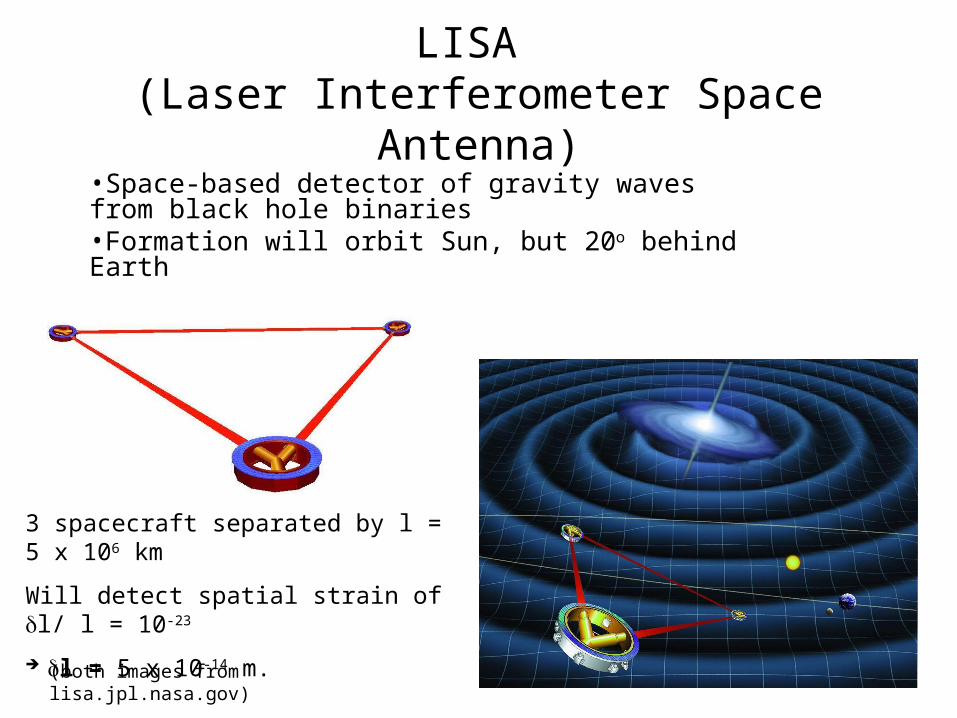
LISA (Laser Interferometer Space Antenna)
•Space-based detector of gravity waves from black hole binaries•Formation will orbit Sun, but 20o behind Earth
3 spacecraft separated by l = 5 x 10⁶ km
Will detect spatial strain of l/ l = 10-23
l = 5 x 10-14 m.
(both images from lisa.jpl.nasa.gov)
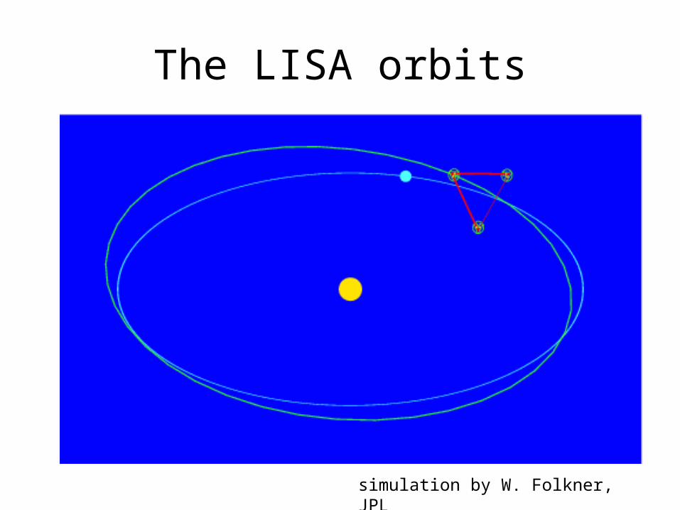
The LISA orbits
simulation by W. Folkner, JPL
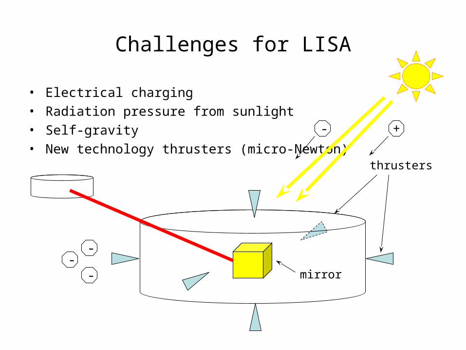
Challenges for LISA
• Electrical charging• Radiation pressure from sunlight• Self-gravity• New technology thrusters (micro-Newton)
mirror
thrusters
- +
--
-
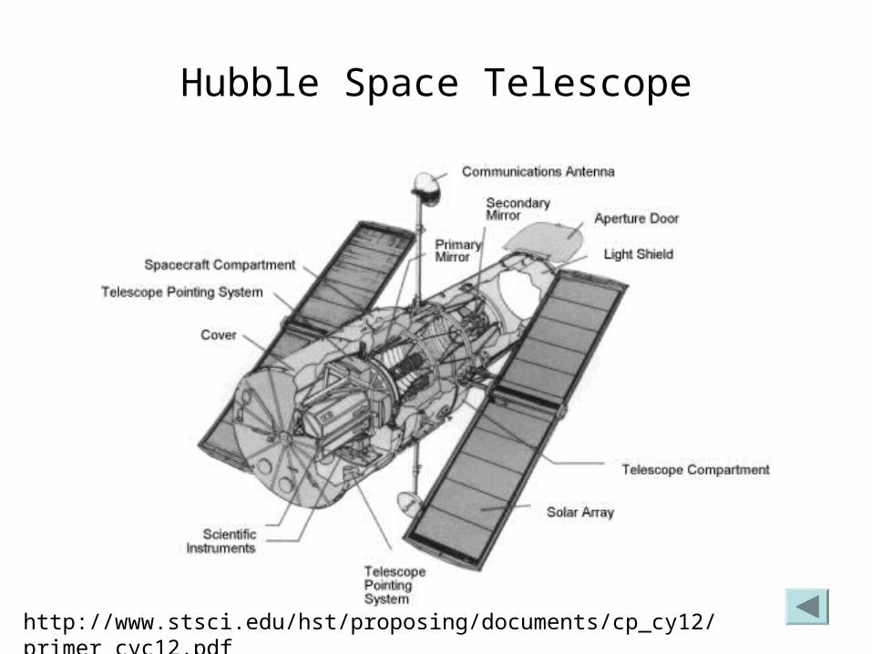
Hubble Space Telescope
http://www.stsci.edu/hst/proposing/documents/cp_cy12/primer_cyc12.pdf
Power
• Solar array: sunlight electrical power– max. efficiency = 17% (231 W/m2 of array)– degrade due to radiation damage 0.5%/year– best for missions 1.53 AU (Mars’ dist. from Sun)
• Radioisotope Thermoelectric Generator (RTG): nuclear decay heat electrical power– max. efficiency = 8% (lots of waste heat!)– best for missions to outer planets– political problems (protests about launching 238PuO2)
• Batteries – good for a few hours, then recharge
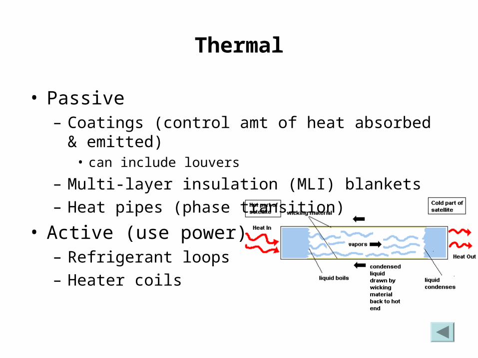
Thermal
• Passive– Coatings (control amt of heat absorbed & emitted)
• can include louvers
– Multi-layer insulation (MLI) blankets– Heat pipes (phase transition)
• Active (use power)– Refrigerant loops– Heater coils
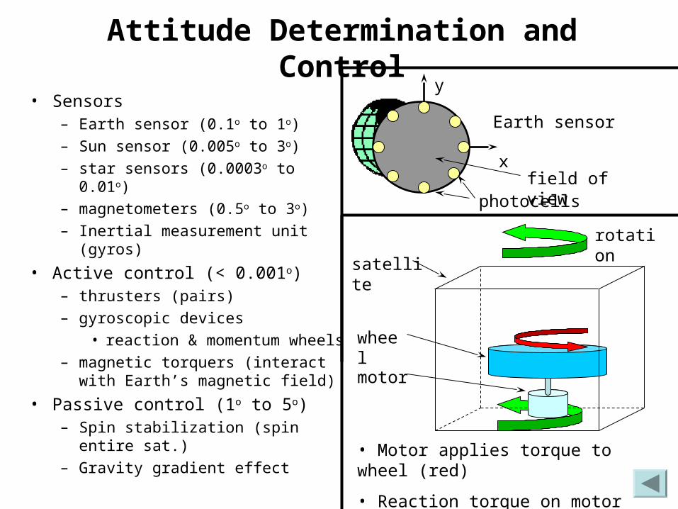
Attitude Determination and Control
• Sensors– Earth sensor (0.1o to 1o)
– Sun sensor (0.005o to 3o)
– star sensors (0.0003o to 0.01o)
– magnetometers (0.5o to 3o)
– Inertial measurement unit (gyros)
• Active control (< 0.001o)– thrusters (pairs)
– gyroscopic devices
• reaction & momentum wheels
– magnetic torquers (interact with Earth’s magnetic field)
• Passive control (1o to 5o)– Spin stabilization (spin entire sat.)
– Gravity gradient effect
x
y
Earth sensor
photocells
wheel
motor
satellite
• Motor applies torque to wheel (red)
• Reaction torque on motor (green) causes satellite to rotate
rotation
field of view
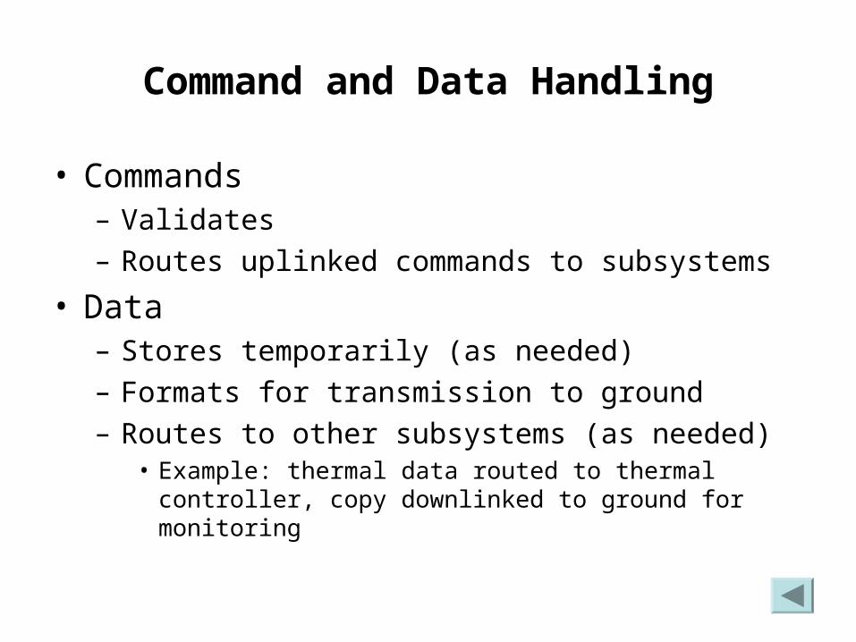
Command and Data Handling
• Commands– Validates – Routes uplinked commands to subsystems
• Data– Stores temporarily (as needed)– Formats for transmission to ground– Routes to other subsystems (as needed)
• Example: thermal data routed to thermal controller, copy downlinked to ground for monitoring
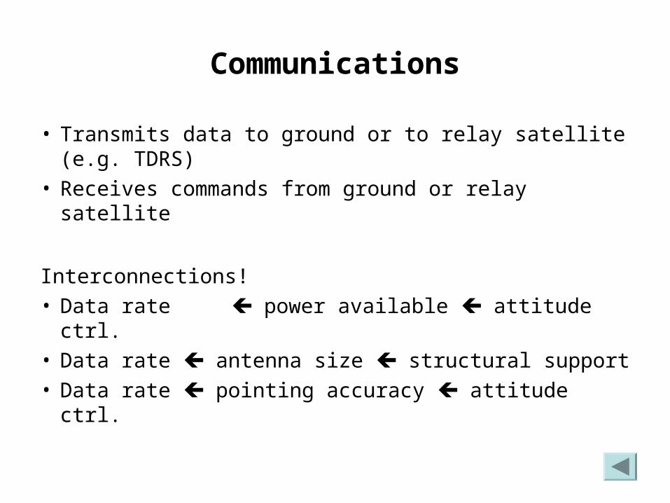
Communications
• Transmits data to ground or to relay satellite (e.g. TDRS)
• Receives commands from ground or relay satellite
Interconnections!• Data rate power available attitude ctrl.• Data rate antenna size structural support• Data rate pointing accuracy attitude ctrl.
Structure
• Not just a coat-rack!• Unifies subsystems• Supports them during launch
– (accel. and vibrational loads)
• Protects them from space debris, dust, etc.
Launch Vehicle
• Boosts satellite from Earth’s surface to space• May have upper stage to transfer satellite to
higher orbit• Provides power and active thermal control
before launch and until satellite deployment
Creates high levels of accel. and vibrational loading
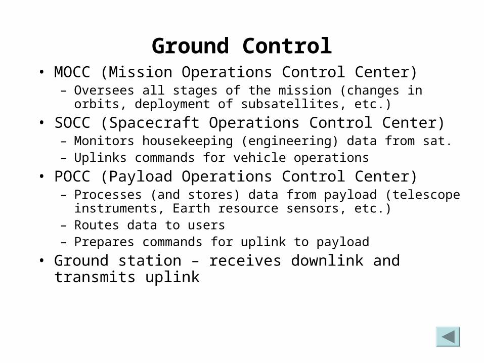
Ground Control• MOCC (Mission Operations Control Center)
– Oversees all stages of the mission (changes in orbits, deployment of subsatellites, etc.)
• SOCC (Spacecraft Operations Control Center)– Monitors housekeeping (engineering) data from sat.– Uplinks commands for vehicle operations
• POCC (Payload Operations Control Center)– Processes (and stores) data from payload (telescope
instruments, Earth resource sensors, etc.)– Routes data to users– Prepares commands for uplink to payload
• Ground station – receives downlink and transmits uplink
Propulsion
• Provides force needed to change satellite’s orbit• Includes thrusters and propellant
Effects of Power on Attitude Control
• Provide properly regulated, adequate levels of electrical power for sensors and actuators
• Failure to meet these requirements could result in incorrect satellite orientation (which affects astron. observations!)
Effects of Attitude Control on Power
• Proper attitude (orientation) needed for solar arrays– some arrays track sun independently but still depend
upon overall satellite orientation control
• Spin-stabilized satellites require electrically switched arrays– high spin rates faster switching
(cheaper attitude ctrl) (more complex electronics)