Embed Size (px)
Citation preview

2001-03-06 IEEE 802.16.3c-01/32
DRAFT
0
Project IEEE 802.16 Broadband Wireless Access Working Group <http://ieee802.org/16>
Title SC-FDE PHY Layer System Proposal for Sub 11 GHz BWA (An OFDMCompatible Solution)
DateSubmitted
2001-03-05
Source(s) Anader Benyamin-SeeyarHarris Corporation Inc.3 Hotel de VilleDollard-des-Ormeaux, Quebec, Canada,H9B 3G4
Co-Contributors:
David Falconer
David Shani, Moshe Ran, Vacit Arat, EranGerson
Demos Kostas, Micheal Yang, Todd Carothe
Remi Chayer, Juan-Carlos Zuniga
Malik Audeh, Frederick Enns, Bob Furniss
Joe Hakim, Subir Varma, Dean Chang
Brian Eidson, Yoav Hebron, J-P Devieux
Sirikat Lek Ariyavisitakul
John Langley
David Fisher, Jerry Krinock, ArvindLonkar, Chin-Chen Lee, Manoneet Singh,Anthony Tsangaropoulos
Paul Struhsaker, Russel McKown GarikMarkarian, David Williams Igor Perlitch,Ed Kevork, Ray Anderson Robert Malkemes Allen Klein
Voice: (514) 822-2014Fax: (514) 421-3756mailto: [email protected]
Institutions:
Carleton University
TelesciCOM Ltd.
Adaptive Broadband Corporation
Harris Corporation Inc.
Hybrid Networks, Inc.
Aperto Networks
Conexant Systems Inc
Broadband Wireless Solutions
Com21, Inc
Radia Communications
Razer Technologies Advanced Hardware Architectures Advantech Sarnoff Wireless technology
SR-Telecom
Re: This contribution is submitted in response to “Call for Contributions: Session #12” by 802.16.3Task Group chair on January 26th, 2001 for submission of “PHY Proposals” for Sub 11 GHz BWA.
Abstract This document provides team PHY System proposal of a low frequency (Sub 11 GHz) wireless accessPHY for point-to-multipoint voice, video and data applications. The submission is for considerationof the Task Group to develop a PHY standard for the TG3 BWA system.
Purpose This contribution will be presented and discussed within the Task Group in Session #12 for possibleadoption as baseline for a PHY standard Sub 11 GHz BWA.
2001-03-06 IEEE 802.16.3c-01/32
DRAFT
1
Notice This document has been prepared to assist IEEE 802.16. It is offered as a basis for discussion and is not binding onthe contributing individual(s) or organization(s). The material in this document is subject to change in form andcontent after further study. The contributor(s) reserve(s) the right to add, amend or withdraw material contained herein.
Release The contributor grants a free, irrevocable license to the IEEE to incorporate text contained in this contribution, andany modifications thereof, in the creation of an IEEE Standards publication; to copyright in the IEEE’s name anyIEEE Standards publication even though it may include portions of this contribution; and at the IEEE’s solediscretion to permit others to reproduce in whole or in part the resulting IEEE Standards publication. The contributoralso acknowledges and accepts that this contribution may be made public by IEEE 802.16.
PatentPolicy andProcedures
The contributor is familiar with the IEEE 802.16 Patent Policy and Procedures (Version 1.0)<http://ieee802.org/16/ipr/patents/policy.html>, including the statement IEEE standards may include the knownuse of patent(s), including patent applications, if there is technical justification in the opinion of the standards-developing committee and provided the IEEE receives assurance from the patent holder that it will license applicantsunder reasonable terms and conditions for the purpose of implementing the standard.
Early disclosure to the Working Group of patent information that might be relevant to the standard is essential toreduce the possibility for delays in the development process and increase the likelihood that the draft publicationwill be approved for publication. Please notify the Chair <mailto:[email protected]> as early as possible, inwritten or electronic form, of any patents (granted or under application) that may cover technology that is underconsideration by or has been approved by IEEE 802.16. The Chair will disclose this notification via the IEEE802.16 web site <http://ieee802.org/16/ipr/patents/notices>

2001-03-06 IEEE 802.16.3c-01/32
DRAFT
2
TABLE OF CONTENTS
1.0 Scope .. . . . . . . . . . . . . . . . . . . . . . . . . . . . . . . . . . . . . . . . . . . . . . . . . . . . . . . . . . . . . . . . . . . . . . . . . . . . . . . . . . . . . . . . . . . . . . 5
2.0 Introduction .. . . . . . . . . . . . . . . . . . . . . . . . . . . . . . . . . . . . . . . . . . . . . . . . . . . . . . . . . . . . . . . . . . . . . . . . . . . . . . . . . . . . . . . 62.1 General 6
2.2 Key Features 7
3.0 PHY Proposal . . . . . . . . . . . . . . . . . . . . . . . . . . . . . . . . . . . . . . . . . . . . . . . . . . . . . . . . . . . . . . . . . . . . . . . . . . . . . . . . . . . . . 83.1 Proposed Wireless Access System Model 8
3.2 Multiple Access Formats and Framing 9
3.2.1 Physical Layer Framing 9
3.2.2 MAC and PHY Interface Layer 21
3.2.2.1 Overview 21
3.2.2.4 Downlink Modes of Operation 29
3.2.3 MAC/ PHY Framing Considerations for Adaptive Antennas38
3.3 Single-Carrier with Frequency Domain Equalization (SC-FDE) Scheme 41
3.3.1 Single Carrier-Frequency Domain Equalization (SC-FDE) and OFDM 42
3.3.2 Compatibility of Single Carrier (SC-FDE) and OFDM 43
3.4 The frequency range and the channel bandwidth 45
3.5 Duplex Schemes 45
3.5.1 TDD: 45
3.5.2 FDD: 45
3.6 Downstream Channel 46
3.6.1 Downstream Multiple Access Scheme 46
3.6.2 Modulation Schemes 46
3.6.3 Downstream Randomization, Channel Coding & Interleaving, Symbol Mapping and Baseband Shaping46
3.7. UpStream Channel 47
3.7.1 Upstream Multiple Access 47
3.7.2 Upstream Modulation Format 48
3.7.3 Upstream Randomization, Channel Coding & Interleaving, Symbol Mapping And Baseband Shaping48
3.8 System Capacity and Modulation Efficiency 49
3.9 RF Propagation Characteristics 50

2001-03-06 IEEE 802.16.3c-01/32
DRAFT
3
3.9.1 RF Network Topology 50
3.9.2 RF bands and Channelization 50
3.9.3 Terrain category: 50
3.9.4 RF propagation impairments: 51
3.9.5 Minimum Performance Specifications 51
3.10 Antenna Systems 51
3.10.1 Application of Smart Antenna 51
3.10.2 Antenna Diversity 51
4.0 Comparative Analysis of OFDM vs SC- FDE: .. . . . . . . . . . . . . . . . . . . . . . . . . . . . . . . . . . . . . . . . . . . . . . .. . . . . . . . . . . . . . . . . . . . . . . . . . . . . . . . . . . . . . . . . . . . . . . . . . . . . . . . . . . . . . . . . . . . . . . . . . . . . . . . . . . . . . . . . . . . . . . . . . . . . . . 51
4.1 Proposed System Robustness 52
4.1.1 Performance in a Fading Channel 52
4.1.1.1 Simulation Assumptions:53
4.1.2 Impact of Phase Noise 60
4.2 Amplifier Linearity Requirements 62
4.4 SC-FDE System Efficiency and Throughput Results 68
4.4 LINK Budget and Cost Factors 70
4.5 Summary and Conclusions: 73
5.0 Main Features and Benefits of the Proposal. . . . . . . . . . . . . . . . . . . . . . . . . . . . . . . . . . . . . . . . . . . . . . . . . . . . 74
6.0 Similarity to other standards:. . . . . . . . . . . . . . . . . . . . . . . . . . . . . . . . . . . . . . . . . . . . . . . . . . . . . . . . . . . . . . . . . . . . . 76
Statement on Intellectual Property Rights:. . . . . . . . . . . . . . . . . . . . . . . . . . . . . . . . . . . . . . . . . . . . . . . . . . . . . . . . . . . . . . . 76
7.0 References:. . . . . . . . . . . . . . . . . . . . . . . . . . . . . . . . . . . . . . . . . . . . . . . . . . . . . . . . . . . . . . . . . . . . . . . . . . . . . . . . . . . . . . . . . 76B.1 Deployment Models 81
B.2 RF Channel Models 81
Turbo Code Description 83
Reed — Solomon Coding 89

2001-03-06 IEEE 802.16.3c-01/32
DRAFT
4
2001-03-06 IEEE 802.16.3c-01/32
DRAFT
5
PHY Layer System Proposal for Single Carrier – FrequencyDomain Equalizer for Sub 11 GHz BWA
(An OFDM Compatible Solution)
Contributors:
Anader Benyamin-Seeyar
David Falconer
David Shani, Moshe Ran, Vacit Arat, EranGerson
Demos Kostas, Micheal Yang, Todd Carothers
Remi Chayer, Juan-Carlos Zuniga
Malik Audeh, Frederick Enns, Bob Furniss
Joe Hakim, Subir Varma, Dean Chang
Brian Eidson, Yoav Hebron, J-P Devieux
Sirikat Lek Ariyavisitakul
John Langley
David Fisher, Jerry Krinock, Arvind Lonkar,
Chin-Chen Lee, Manoneet Singh, AnthonyTsangaropoulos
Paul Struhsaker, Russel McKown
Garik Markarian, David Williams
Igor Perlitch, Ed Kevork, Ray Anderson
Robert Malkemes
Allen Klein
Institutions:
Harris Corporation Inc.
Carleton University
TelesciCOM Ltd.
Adaptive Broadband Corporation
Harris Corporation Inc.
Hybrid Networks, Inc.
Aperto Networks
Conexant Systems Inc
Broadband Wireless Solutions
Com21, Inc
Radia Communications
Razer Technologies
Advanced Hardware Architectures
Advantech
Sarnoff Wireless technology
SR-Telecom
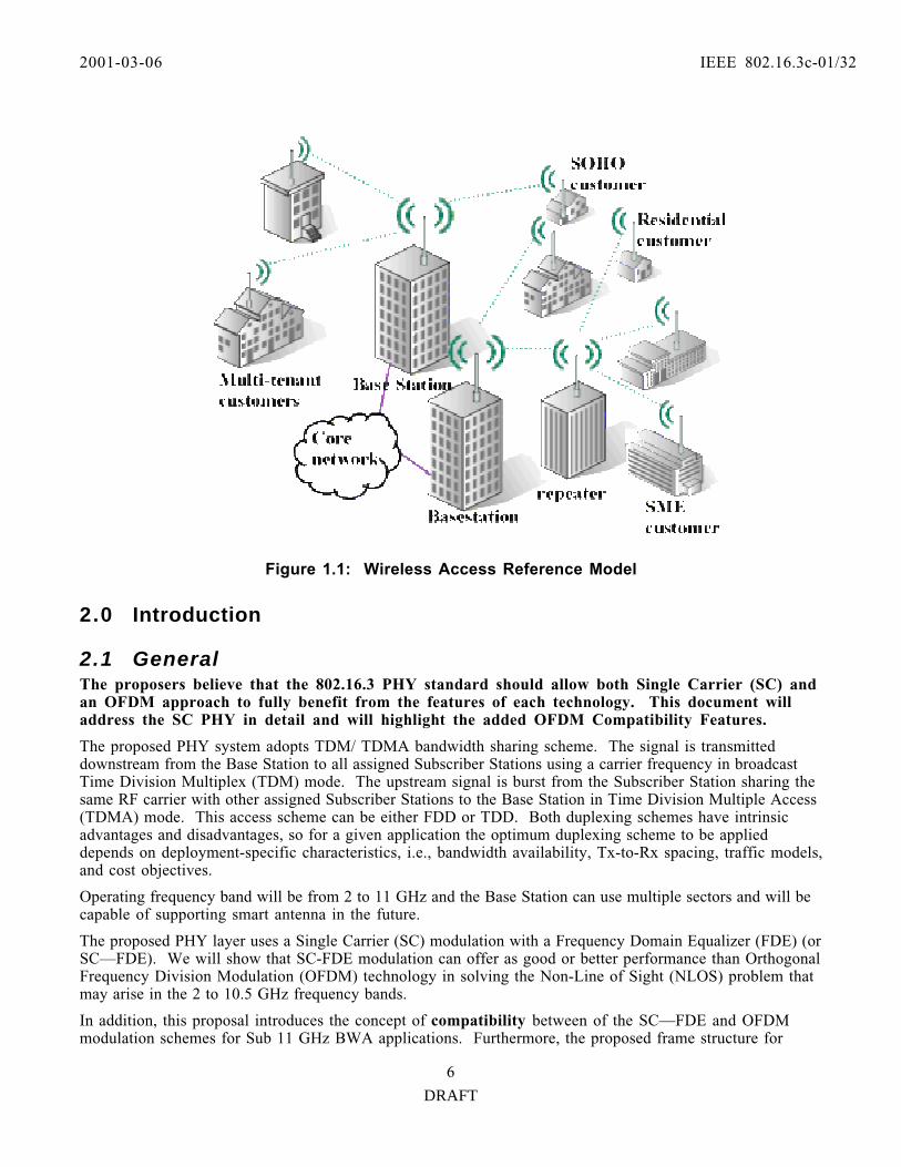
1.0 ScopeThis document defines a proposed Physical Layer (PHY) for IEEE802.16.3 Broadband Wireless Access(BWA) systems in licensed frequency bands from 2-11GHz. Fixed BWA is a communication system thatprovides digital two-way voice, data, and video services. The BWA market targets wireless multimediaservices to home offices, small and medium-sized businesses and residences. The BWA system shall be apoint-to-multipoint architecture comprise of Subscriber Stations (SS) and Base Stations (BS, Hubstation). Figure 1.1 illustrates a BWA reference model.
2001-03-06 IEEE 802.16.3c-01/32
DRAFT
6
Figure 1.1: Wireless Access Reference Model
2.0 Introduction
2.1 GeneralThe proposers believe that the 802.16.3 PHY standard should allow both Single Carrier (SC) andan OFDM approach to fully benefit from the features of each technology. This document willaddress the SC PHY in detail and will highlight the added OFDM Compatibility Features.
The proposed PHY system adopts TDM/ TDMA bandwidth sharing scheme. The signal is transmitteddownstream from the Base Station to all assigned Subscriber Stations using a carrier frequency in broadcastTime Division Multiplex (TDM) mode. The upstream signal is burst from the Subscriber Station sharing thesame RF carrier with other assigned Subscriber Stations to the Base Station in Time Division Multiple Access(TDMA) mode. This access scheme can be either FDD or TDD. Both duplexing schemes have intrinsicadvantages and disadvantages, so for a given application the optimum duplexing scheme to be applieddepends on deployment-specific characteristics, i.e., bandwidth availability, Tx-to-Rx spacing, traffic models,and cost objectives.
Operating frequency band will be from 2 to 11 GHz and the Base Station can use multiple sectors and will becapable of supporting smart antenna in the future.
The proposed PHY layer uses a Single Carrier (SC) modulation with a Frequency Domain Equalizer (FDE) (orSC—FDE). We will show that SC-FDE modulation can offer as good or better performance than OrthogonalFrequency Division Modulation (OFDM) technology in solving the Non-Line of Sight (NLOS) problem thatmay arise in the 2 to 10.5 GHz frequency bands.
In addition, this proposal introduces the concept of compatibility between of the SC—FDE and OFDMmodulation schemes for Sub 11 GHz BWA applications. Furthermore, the proposed frame structure for
2001-03-06 IEEE 802.16.3c-01/32
DRAFT
7
adaptive modulation and coding is an ideal approach to make PHY almost independent from the MAC. ThePHY proposed here is based upon utilizing the structure of the 802.16 MAC.
The key benefits of the proposed PHY include:
1) Mature and well-proven technology
2) Adaptive Modulation and Coding
3) Flexible Asymmetry of Downstream and Upstream Paths
4) Scalability
5) Advanced Coding Schemes
6) Reduced System Delay
7) Easy Migration from simple SC with Time Domain Equalizer (SC-TDE) to SC—FDE.
8) Straight forward migration to diversity receiver and multiple-input/multiple-output (MIMOtechnology)
9) The proposed PHY is flexible to accommodate OFDM modulation when OFDM permits aneconomically viable solution.
In brief we note that:
• For severe multipath, Single Carrier QAM with simplified frequency-domain equalization performs atleast as well as OFDM (better for uncoded systems).
• Frequency domain linear equalization has essentially the same complexity as uncoded OFDM, with betterperformance in frequency selective fading, and without OFDM s inherent backoff power penalty.
• A Compatible frequency domain receiver structure can be programmed to handle either OFDM orSingle Carrier.
• Downlink OFDM / uplink single carrier may yield potential complexity reduction and uplink powerefficiency gains relative to downlink OFDM / uplink OFDM.
2.2 Key FeaturesThe PHY proposed here is a Broadband Wireless Access (BWA) Point-to-Multipoint communicationsystem that can provide digital, two-way voice, data, Internet and video services. Proposed PHY offers aneffective alternative to traditional wire line (cable or DSL) services.
Employing the functions of the 802.16 MAC such as QoS, the BWA system using the PHY proposed herewill support services; such as packet data and Constant Bit Rate (CBR) as well as T1-E1, POTS, wide bandaudio and video services.
To maximize the utilization of limited spectrum resources in the low frequency bands (2 to 11 GHz), the air-interface supports upstream statistical multiplexing over the air-interface using Time Division MultipleAccess (TDMA) technology.
The main features of the proposal are the following:
• Full compatibility with the 802.16 MAC.• Upstream multiple access scheme is based on TDMA.• Downstream multiple access scheme is based on broadcast TDM.

2001-03-06 IEEE 802.16.3c-01/32
DRAFT
8
• Duplexing is based on either TDD or FDD scheme.• PHY uses a block adaptive modulation and FEC coding in both Upstream and Downstream paths.• High capacity single carrier modulation with frequency Domain Equalization (SC-FDE) in addition to
Decision Feedback Equalization in the time domain.• The use of single carrier modulation techniques can result in low cost Subscriber Stations (SS) and
Base Stations (BS).• The proposed modulation scheme is robust in multi-path and other channel impairments• The PHY is flexible in terms of geographic coverage, in the use of frequency band, and capacity
allocation.• Base Station can use multiple sector antennas. Support for future use of smart antennas is feasible
and is implicit in the PHY design.• The PHY can easily accommodate multi-beam and antenna diversity options; such as Multiple-In
Multiple-Out (MIMO) and Delay diversity.• The proposed PHY has an added feature of reconfigurability to support OFDM modulation.
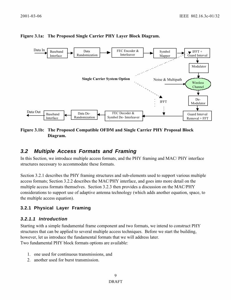
3.0 PHY ProposalAs described in the Functional Requirement Document [1], equipment employing this PHY and the802.16 MAC have been designed to address the critical parameters for serving single family residential,SOHO, small businesses and multi-tenant dwellings customers--using Broadband Wireless Accesstechnology. These critical parameters are combination of coverage, capacity and equipment cost factorsthat affect total cost per user. The proposed PHY facilitates deployability, maintainability, and productcosts associated with the customer premise installation, and the spectrum efficiency and reuse foreconomically serving the required number of customer locations. Of particular importance to theproposed PHY presented here is the inherent versatility implicit in the Frequency Domain Equalizer(FDE) architecture. Conceptually, a dual mode receiver could be implemented in which the FDEconfiguration could be changed to receive an OFDM signal. The bases for this approach are shown inFigure 3.22.
3.1 Proposed Wireless Access System ModelFigure 3.1 is a top level block diagram of the proposed PHY layer system for BWA services. Figure 3.1ais an illustration for Single carrier system and Figure 3.1b is the Compatible OFDM system.
BasebandInterface
DataScrambler
FEC Encode&
InterleaverModulator
Upconverter&
Synthesizers
PowerAmplifier
BasebandInterface
DataDescrambler
FEC Decode&
De-Interleaver
CarrierRecovery
&Demod
Downconverter&
Synthesizers
LowNoise
Amplifier
Frequency& TimeDomain
Equalizers
Data In
DataOut
Wireless Channel AWGNMultipath
2001-03-06 IEEE 802.16.3c-01/32
DRAFT
9
Figure 3.1a: The Proposed Single Carrier PHY Layer Block Diagram.
Figure 3.1b: The Proposed Compatible OFDM and Single Carrier PHY Proposal BlockDiagram.
3.2 Multiple Access Formats and FramingIn this Section, we introduce multiple access formats, and the PHY framing and MAC/ PHY interfacestructures necessary to accommodate these formats.
Section 3.2.1 describes the PHY framing structures and sub-elements used to support various multipleaccess formats; Section 3.2.2 describes the MAC/PHY interface, and goes into more detail on themultiple access formats themselves. Section 3.2.3 then provides a discussion on the MAC/PHYconsiderations to support use of adaptive antenna technology (which adds another equation, space, tothe multiple access equation).
3.2.1 Physical Layer Framing
3.2.1.1 Introduction
Starting with a simple fundamental frame component and two formats, we intend to construct PHYstructures that can be applied to several multiple access techniques. Before we start the building,however, let us introduce the fundamental formats that we will address later.Two fundamental PHY block formats options are available:
1. one used for continuous transmissions, and2. another used for burst transmission.
Data In
Data Out
BasebandInterface
DataRandomization
FEC Encoder &Interleaver
SymbolMapper
IFFT +Guard Interval
Modulator
BasebandInterface
Data De-Randomization
FEC Decoder &Symbol De- Interleaver
WirelessChannel
Noise & Multipath
De-Modulator
Guard IntervalRemoval + FFT
Single Carrier System Option
IFFT

2001-03-06 IEEE 802.16.3c-01/32
DRAFT
10
The continuous transmission format is used on the downstream of one type of a FDD system. Theburst format might be seen on the upstream of a FDD system, or on the upstream and downstream of aTDD system or on the downstream of a burst-FDD system. The burst format may be furthercategorized into TDMA and TDM sub-formats. A TDMA burst contains information intended for oneaudience (which could be a single user, or a broadcast user). In contrast a TDM burst containsmultiplexed, concatenated information addressed to multiple audiences.
3.2.1.2 Continuous Transmission Format
As its name suggests, the continuous transmission format is utilized for a continuous channel, which istracked by all Subscriber Stations (SS)s within a Base Station (BS) cell sector. In the broadband wirelessapplication, this would be a (continuous) FDD downstream channel.
The format for continuous transmission is illustrated in Figure 3.1. Note that continuous channel has asimple pattern that repeats itself. This pattern consists of N-symbol payloads separated by uncoded, U-symbol Unique Words .
Usymb
UW UWPayloadN symbs
Unique Word(Pilot Sequence)Every N symbols
PayloadN symbs
UW... PayloadN symbs
UW ...
Note: When no data is available to be sent,part of a payload may be empty. However
the UWs, which are used for trackingpurposes, will always be transmitted
Figure 3.1: Block Format for Continuous Transmission
3.2.1.2.1 The Unique WordThe Unique Words may be used as cyclic prefixes by a frequency domain equalizer, and/or as pilot symbols. When used as cyclic prefixes, the Unique Words should at least be as long as the maximum delay spread of achannel. When used as pilot symbols, the Unique Words may assist in the estimation of demodulationparameters, such as equalizer channel coefficients, carrier phase and frequency offsets, symbol timing, andFFT window timing. They may also assist in initial acquisition of a channel.
The interval for the Unique Words is chosen to facilitate frequency domain equalization, with N+U= Fsymbols equaling the block length over which the FFT used by a frequency domain equalizer would becomputed. To reduce computational requirements of the FFT, N+U=F should preferably be a power of 2.
3.2.1.2.2 Adaptive Modulation
3.2.1.2.2.1 Introduction to Adaptive Modulation
Many SSs receive the continuous downstream channel. Due to differing conditions at the various SSsites (e.g., variable distances from the BS, presence of obstructions), SS receivers may observesignificantly different SNRs. For this reason, some SSs may be capable of reliably detecting (non-pilot)data only when it is derived from certain lower-order modulation alphabets, such as QPSK. Similarly,

2001-03-06 IEEE 802.16.3c-01/32
DRAFT
11
SNR-disadvantaged SSs may require more powerful and redundant FEC schemes. On the other hand,SNR-advantaged stations may be capable of receiving very high order modulations (e.g., 64-QAM), withhigh code rates. Obviously, to maximize the overall capacity of the system, the modulation and codingformat should be adapted to each class of SS, based on what the SS can receive reliably. Define theadaptation of modulation type and FEC to a particular SS (or group of SSs) as ’adaptive modulation’, andthe choice of a particular modulation and FEC as an ’adaptive modulation type.’ The continuoustransmission mode (as does the burst transmission mode) supports adaptive modulation and the use ofadaptive modulation types.
3.2.1.2.2.2 Frame Control Header Information
Frame Control MAC messages are periodically transmitted over the continuous channel, using the mostrobust supported adaptive modulation type. These Frame Control headers provide adaptive modulationtype formatting instructions. So that, the beginning of MAC message containing Frame Control headersmay be easily recognized during initial channel acquisition or re-acquisition, the transmitter PHY insertsan uncoded, TBD (known) uncoded QPSK code word, of length TBD symbols, immediately before thebeginning of a MAC message containing Frame Control information, and immediately after a UniqueWord. Note that this implies the interval between broadcasts containing DL_MAPs should be an integermultiple of F (the interval between Unique Words). 3.2.1.2.2.3 Adaptive Modulation Sequencing
Within the MAC, a PHY control map (DL_MAP) is used to indicate the beginning location of each ofadaptive modulation type payload that follows. However, the DL_MAP does not describe the beginninglocations of the payload groups that immediately follow; it describes the payload distributions someMAC-prescribed time in the future. This delay is necessary so that FEC decoding of MAC information(which could be iterative, in the case of turbo codes) may be completed, the adaptive data interpreted,and the demodulator scheduling set up for the proper sequencing.
Following DL_MAP instructions, payload groups are sequenced in increasing order of robustness (e.g.,first QPSK, then 16-QAM, then 64-QAM). This improves the receiver performance, because this forcesthem to track only the modulation types that they can reliably receive. This sequencing also facilitateschanges of modulation type at locations that are not contiguous to Unique Word boundaries.
3.2.1.2.2.4 UW Boundary-free Transitions Between Modulation Types
Note also that adaptive modulation type-to-other-modulation type changes are not restricted to occuronly at Unique Word boundaries. They may change anywhere that the DL_MAP message indicates thatthey should change.
3.2.1.2.2.5 Per-Adaptive Modulation Type FEC Encapsulation
So that disadvantaged-SNR SSs are not adversely affected by transmissions intended for otheradvantaged-SNR users, FEC blocks end when a particular adaptive modulation type ends. Among other

2001-03-06 IEEE 802.16.3c-01/32
DRAFT
12
things, this implies that the FEC interleaver depth and code blocks are adapted to accommodate the spanof a particular adaptive modulation type.
3.2.1.2.3 Empty payloads
Note, as Figure 3.1 illustrates, when data is available for transmission, part of a payload may be empty.However, the transmitter cannot shut completely down. The unique words are always transmitted, sothat all listening SSs may track the channel, and maintain synchronization.
3.2.1.2.4 Additional Pilot Symbols
When multipath delay spread spans almost the entire unique word interval, very little data remains thatis not uncorrupted by delay spread from the arbitrary, a priori unknown payload symbols. In such anenvironment, non-decision aided channel (delay profile) estimation could become increasingly difficult. The only recourse, then, would be increased utilization of decision-aided channel estimation.
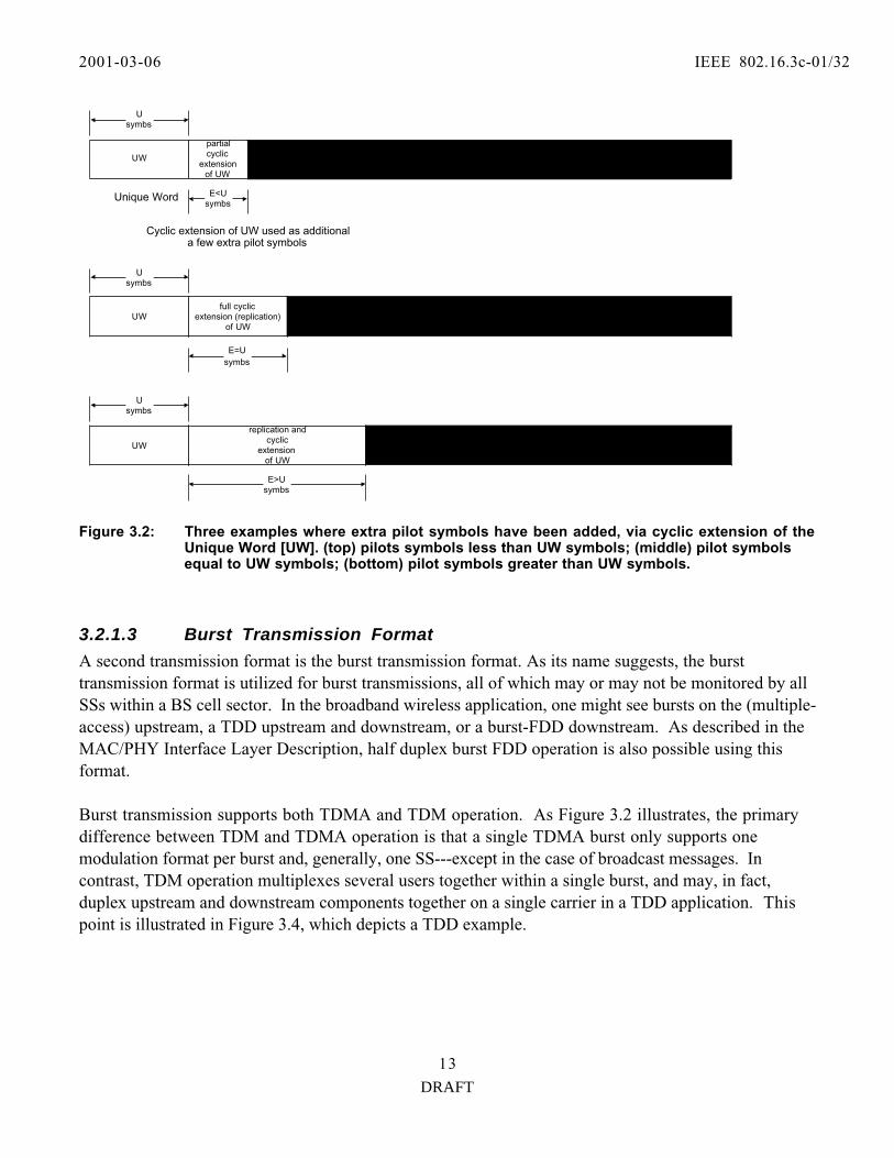
To add an extra measure of robustness, many system operators may prefer, instead, to opt for theaddition of additional pilot symbols. For this reason, the addition of extra pilot symbols is allowed, as(contiguous) cyclic extensions of the Unique Word. Figure 3.2 illustrates three cases where pilotsymbols have been added: one for a case when only a few symbols have been added, another where thenumber of added pilot symbols and Unique Word symbols are the same (i.e., the Unique Word has beenreplicated), and one for a case where the number of pilot symbols is much greater than the number ofUnique Word symbols (i.e., where the UW is replicated at least once, then cyclically extended.)
2001-03-06 IEEE 802.16.3c-01/32
DRAFT
13
Usymbs
Unique Word
PayloadN-E symbs
UW
...
Cyclic extension of UW used as additionala few extra pilot symbols
partialcyclic
extensionof UW
E<Usymbs
UWfull cyclic
extension (replication)of UW
PayloadN-E = N-U symbs
E=Usymbs
Usymbs
UW
replication andcyclic
extensionof UW
Usymbs
E>Usymbs
PayloadN-E symbs
Figure 3.2: Three examples where extra pilot symbols have been added, via cyclic extension of theUnique Word [UW]. (top) pilots symbols less than UW symbols; (middle) pilot symbolsequal to UW symbols; (bottom) pilot symbols greater than UW symbols.
3.2.1.3 Burst Transmission Format
A second transmission format is the burst transmission format. As its name suggests, the bursttransmission format is utilized for burst transmissions, all of which may or may not be monitored by allSSs within a BS cell sector. In the broadband wireless application, one might see bursts on the (multiple-access) upstream, a TDD upstream and downstream, or a burst-FDD downstream. As described in theMAC/PHY Interface Layer Description, half duplex burst FDD operation is also possible using thisformat.
Burst transmission supports both TDMA and TDM operation. As Figure 3.2 illustrates, the primarydifference between TDM and TDMA operation is that a single TDMA burst only supports onemodulation format per burst and, generally, one SS---except in the case of broadcast messages. Incontrast, TDM operation multiplexes several users together within a single burst, and may, in fact,duplex upstream and downstream components together on a single carrier in a TDD application. Thispoint is illustrated in Figure 3.4, which depicts a TDD example.

2001-03-06 IEEE 802.16.3c-01/32
DRAFT
14
TDMA1:Single Payload/One Modulation Type, e.g.,
QPSK
TDMA2:Single Payload/One
Modulation Type, e.g.,64-QAM
QPSK Payload 64-QAM Payload
TDM: ContiguousMultiple Payloads
within a burst
TDMA:Per-BurstPayload
TDMA:Per-BurstPayload
Figure 3.3: Comparison of a TDMA and a TDD Burst
M Mini Slots
DownlinkSubframe Uplink Subframe
Guardband
MS n MS (n+ M)
Figure 3.4: Example of a TDD Frame.
3.2.1.3.1 Burst TDMA Operation
As previously indicated, TDMA bursts are bursts targeted at one audience. Since SSs typically onlycontain one user, burst TDMA is the transmission format for all upstream transmissions. They mayalso include downstream transmissions in a burst-FDD application with no user concatenation.

2001-03-06 IEEE 802.16.3c-01/32
DRAFT
15
The burst TDMA format is illustrated Figure 3.5. Note that this format is much the same as the continuous format, with the periodic insertion of UniqueWords. These Unique Words facilitate frequency domain equalization, and also assist in demodulatorparameter estimation and tracking. Unlike the continuous format, however, the burst has a beginningpoint, and an ending point.
Uupsymb
Asymb
AcquisitionPreamble
M symbs(Payload)UW UW...
Length "A" mayvary accordingto modulation
type in a TDMAapplication
UWM symbs(Payload)UW
Uupsymb
Uupsymb
UW used asguard interval
N<M symbs(Final
Payloadblock)
UW
Possible to shorten componentblocks so that FFTs are of length
two to various powers. This enabletransmission of packets of variablesizes. The receiver would equalizethe shortened component packet
with a shorter FFT.
Repetitions ofUW used to form
solid channelestimate
Figure 3. 5: Block Format for Burst TDMA Transmission.
3.2.1.3.1.1 TDMA Burst Elements
At the head of the burst, is an initial Unique Word. This Unique Word serves primarily as a guardinterval. It may be used to ramp up the transmitter. At the receiver it may act as a guard interval fordelay spread from another multiple access user, after that user has stopped transmitting. What s more,the receiver may sample the initial part of the Unique Word, and use it to determine which antenna isbest to be used in a low-cost antenna switching diversity receiver implementation.
Following the initial Unique Word, is an acquisition preamble. This preamble is used to obtain a goodestimate of the channel, and is composed of replicas of the Unique Word.
All subsequent Unique Words are used as cyclic prefixes for frequency domain equalization and/or aspilot symbols for demodulator parameter estimation and tracking.
2001-03-06 IEEE 802.16.3c-01/32
DRAFT
16
The frame terminates with a Unique Word following the final payload block. This enables a receiver toapply frequency domain equalization to the final payload block. Note that if extra ramp down symbolsare needed, the Unique Word can be cyclically extended.
3.2.1.3.1.2 Variable Burst Sizes
A characteristic of the burst format is that, for efficient operation, it may be necessary to accommodatemany different burst sizes. These burst sizes could be different from some integer multiple of thenominal FFT size, F=M+Uup, of a frequency domain equalizer.
3.2.1.3.1.2.1 Variable Burst Sizes and Frequency Domain Equalizers
Even for implementations using a frequency domain equalizer, the single carrier burst PHY usingfrequency domain has some flexibility in this regard. For messages intended for a receiver with afrequency domain equalizer, the final payload block can be shortened to the length Mshort, under theconstraints Mshort+Uup = 2n , n is an integer, and 2n ≥Uup .
Shortened block processing is feasible at the receiver because the same FFT hardware can be reused forFFTs of length 2 to smaller powers. What s more, in at least one channel estimation implementation, thechannel (delay spread profile) may be estimated in the time domain, zero-padded to the proper FFTlength, and then FFTed to form an interpolated frequency estimate. Since interpolation is generally usedfor the longer block lengths, and less interpolation is actually used for the shortened block lengths, theonly necessity in this application context is that the FFT used by the frequency domain equalizer be atleast the length of the temporal channel estimate.
3.2.1.3.1.2.2 Variable Burst Sizes and Time Domain Equalizers
For receivers using time domain equalizers (such as decision feedback equalizers), the shortened length of thelast block, Mshort, can be completely arbitrary, and is only limited by MAC packet length granularityrestrictions.
3.2.1.3.1.2.3 Variable Length Negotiation
Exchange of information regarding receiver capabilities during initial registration is one method to ensurethat message granularities always conform to a burst receiver s capabilities to process them.
3.2.1.3.1.2.4 Broadcast Messages
Broadcast messages would always be sent assuming a frequency domain equalizer s granularity limitations,since those limitations are more restrictive.
3.2.1.3.1.3 Adaptive Modulation
In the TDMA application, only one audience exists for a particular burst message, so no modulationchanges occur within the burst. (With the exception of the fact that the pilot symbols and UniqueWords may not be derived from the same alphabet as the payload symbols.) However any given burstmay have a different modulation type, as directed by a DL_MAP message sent down from the MAC.

2001-03-06 IEEE 802.16.3c-01/32
DRAFT
17
3.2.1.3.1.4 Additional Pilot Symbols
To add an extra measure of robustness to transmission, additional pilot symbols, may be added to aTDMA transmission. The additional pilot symbols would be contiguous cyclic extensions of theperiodically inserted Unique Words already found in the burst. Figure 3.2 illustrates some examples ofhow these additional symbols might be added.
A MAC burst profile determines whether or not these additional pilot symbols will be inserted.
3.2.1.3.2 Burst TDM Operation
In addition to TDMA bursts, another type of burst format is accommodated: TDM bursts.As previously indicated (and illustrated in Figure 3.3), TDM bursts target multi-party audiences, withdifferent payloads addressed to different SSs. What s more, TDM bursts may be bi-directional, as is thecase with TDD (see Figure 3.4).
Some applications that use burst TDM are the aforesaid TDD, as well as burst-FDD downstreams,which concatenate packets intended for several SSs together.
3.2.1.3.2.1 Block Format for Burst TDM Transmission
Burst TDM is somewhat an amalgam of the continuous transmission and burst TDMA transmission.The block format is identical to the block format illustrated for TDMA in Figure 3.5.
At the head of the burst, is an initial Unique Word. This Unique Word serves primarily as a guardinterval. It may be used to ramp up the transmitter. At the receiver it may act as a guard interval fordelay spread from another multiple access user, after that user has stopped transmitting. What s more,the receiver may sample the initial part of the Unique Word, and use it to determine which antenna isbest to be used in a low-cost antenna switching diversity receiver implementation.Following the initial Unique Word, is an acquisition preamble. This preamble is used to obtain a goodestimate of the channel, and is composed of replicas of the Unique Word.
All subsequent Unique Words are used as cyclic prefixes for frequency domain equalization and/or aspilot symbols for demodulator parameter estimation and tracking.
The frame terminates with a Unique Word following the final payload block. By so terminating theblock, a receiver may frequency domain equalization on the final payload block. Note that if extra rampdown symbols is needed, the Unique Word can be cyclically extended.
3.2.1.3.2.2 Variable Burst Sizes
A characteristic of the burst format is that, for efficient operation, it may be necessary to accommodatemany different burst sizes. These burst sizes could be different from some integer multiple of thenominal FFT size, F=M+Uup, of a frequency domain equalizer.
2001-03-06 IEEE 802.16.3c-01/32
DRAFT
18
3.2.1.3.2.2.1 Variable Burst Sizes and Frequency Domain Equalizers
Even for implementations using a frequency domain equalizer, the single carrier burst PHY usingfrequency domain has some flexibility in this regard. For messages intended for a group of receivers witha frequency domain equalizer, the final payload block can be shortened to the length Mshort, under theconstraints Mshort+Uup = 2n , n is an integer, and 2n ≥Uup.
3.2.1.3.2.2.2 Variable Burst Sizes and Time Domain Equalizers
For groups of receivers using time domain equalizers (such as decision feedback equalizers), theshortened length of the last block, Mshort, can be completely arbitrary, and is only limited by MACpacket length granularity restrictions.
3.2.1.3.2.2.3 Variable Burst Length Negotiation
Exchange of information regarding receiver capabilities during initial registration is one method to ensurethat message granularities always conform to a burst receiver s capabilities to process them. If any onereceiver in a TDM group is incapable of equalizing arbitrary block sizes, the frequency domain equalizerblock size restrictions are enforced, since they are more restrictive. Burst profiles derived from theMAC designate the format of transmitted blocks.
3.2.1.3.2.3 Adaptive Modulation
In the TDM application, several payloads are borne, and addressed to destinations. Due to differingpropagation conditions, the destination receivers may observe significantly different SNRs. For thisreason, some receivers may be capable of reliably detecting (non-pilot) data only when it is derived fromcertain lower-order modulation alphabets, such as QPSK. Similarly, SNR-disadvantaged receivers mayrequire more powerful and redundant FEC schemes. On the other hand, SNR-advantaged stations maybe capable of receiving very high order modulations (e.g., 64-QAM), with high code rates. Obviously, tomaximize the overall capacity of the system, the modulation and coding format should be adapted toeach class of receiver, based on what the receiver can reliability decode. Define the adaptation ofmodulation type and FEC to a particular SS (or group of SSs) as ’adaptive modulation’, and the choice ofa particular modulation and FEC as an ’adaptive modulation type.’ The continuous transmission mode(as does the burst transmission mode) supports adaptive modulation and the use of adaptive modulationtypes.
3.2.1.3.2.3.1 Frame Control Header Information
Frame Control MAC messages are periodically transmitted, using the most robust supported adaptivemodulation type. These Frame Control headers provide adaptive modulation type formattinginstructions for TDM bursts which follow. 3.2.1.3.2.3.2 Adaptive Modulation Sequencing
Following DL_MAP instructions, payload groups are sequenced in increasing order of robustness (e.g.,first QPSK, then 16-QAM, then 64-QAM) within a packet. This improves the receiver performance,
2001-03-06 IEEE 802.16.3c-01/32
DRAFT
19
because this forces them to track only the modulation types that they can reliably receive. This alsofacilitates changes of modulation type at locations that are contiguous to Unique Word boundaries.
3.2.1.3.2.3.3 UW Boundary-free Transitions Between Modulation Types
Note also that adaptive modulation type-to-other-modulation type changes are not restricted to occuronly at Unique Word boundaries. They may change anywhere that the DL_MAP message indicates thatthey should change.
3.2.1.3.2.3.4 Per-Adaptive Modulation Type FEC Encapsulation
So that disadvantaged-SNR SSs are not adversely affected by transmissions intended for otheradvantaged-SNR users, FEC blocks always end when a particular adaptive modulation type ends. Among other things, this implies that the FEC interleaver depth and code blocks are adapted toaccommodate the span of a particular adaptive modulation type. Depending on the burst profile, thesebursts may terminate earlier, on an addressee-by-addressee basis.
3.2.1.3.1.4 Additional Pilot Symbols
To add an extra measure of robustness to transmission, additional pilot symbols, may be added to aTDMA transmission. The additional pilot symbols would be contiguous cyclic extensions of theperiodically inserted Unique Words already found in the burst. Figure 3.2 illustrates some examples ofhow these additional symbols might be added.
3.2.1.4 Unique Word
The Unique Word is omnipresent, appearing in all frame structures, for both continuous and burstformats.
3.2.1.4.1 Design Criteria
The choice of Unique Word is critical, because it is used as both a Cyclic prefix for frequency domainequalizers, and also for channel estimation. Its cyclic prefix role imposes one constraint: the UniqueWord must be at least as long as the maximum delay spread to be experienced by an intended receiver. Itschannel estimation role imposes another constraint: the Unique Word should have good correlationproperties, and a broadband, un-notched frequency response. And lastly, since the Unique Wordintroduces overhead, it should be no longer than it need be; sectors/installations that experience less delayspread should not be burdened with the overhead of excessively long Unique Words. This implies thatsome flexibility in the choice (or construction) of Unique Words is required.
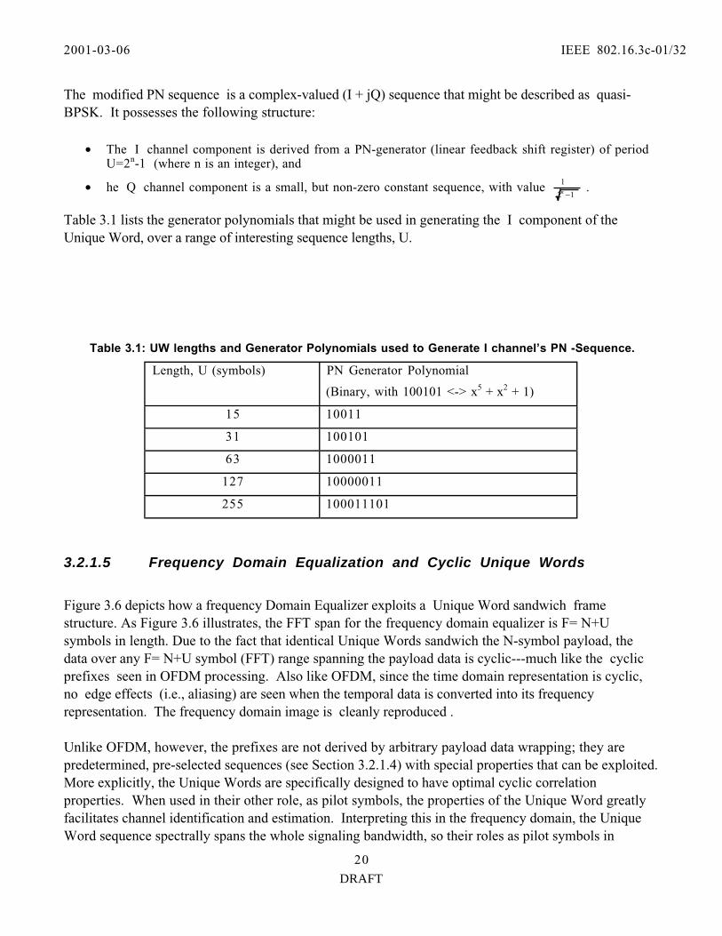
3.2.1.4.2 Specification
One sequence class that seems to possess all of the desired properties is the modified PN sequence, asdescribed by Milewski in [26]. As the title suggests in [26], this sequence class has optimal propertiesfor channel estimation and fast start-up equalization. What s more, constructions for various sequencelengths are simple, due to their derivation from PN sequences.
2001-03-06 IEEE 802.16.3c-01/32
DRAFT
20
The modified PN sequence is a complex-valued (I + jQ) sequence that might be described as quasi-BPSK. It possesses the following structure:
• The I channel component is derived from a PN-generator (linear feedback shift register) of periodU=2n-1 (where n is an integer), and
• he Q channel component is a small, but non-zero constant sequence, with value 12
1
−n .
Table 3.1 lists the generator polynomials that might be used in generating the I component of theUnique Word, over a range of interesting sequence lengths, U.
Table 3.1: UW lengths and Generator Polynomials used to Generate I channel’s PN -Sequence.
Length, U (symbols) PN Generator Polynomial
(Binary, with 100101 <-> x5 + x2 + 1)
15 10011
31 100101
63 1000011
127 10000011
255 100011101
3.2.1.5 Frequency Domain Equalization and Cyclic Unique Words
Figure 3.6 depicts how a frequency Domain Equalizer exploits a Unique Word sandwich framestructure. As Figure 3.6 illustrates, the FFT span for the frequency domain equalizer is F= N+Usymbols in length. Due to the fact that identical Unique Words sandwich the N-symbol payload, thedata over any F= N+U symbol (FFT) range spanning the payload data is cyclic---much like the cyclicprefixes seen in OFDM processing. Also like OFDM, since the time domain representation is cyclic,no edge effects (i.e., aliasing) are seen when the temporal data is converted into its frequencyrepresentation. The frequency domain image is cleanly reproduced .
Unlike OFDM, however, the prefixes are not derived by arbitrary payload data wrapping; they arepredetermined, pre-selected sequences (see Section 3.2.1.4) with special properties that can be exploited.More explicitly, the Unique Words are specifically designed to have optimal cyclic correlationproperties. When used in their other role, as pilot symbols, the properties of the Unique Word greatlyfacilitates channel identification and estimation. Interpreting this in the frequency domain, the UniqueWord sequence spectrally spans the whole signaling bandwidth, so their roles as pilot symbols in

2001-03-06 IEEE 802.16.3c-01/32
DRAFT
21
channel estimation are not diminished due to frequency selective fading. (This cannot be said for thepilot tones used by OFDM, because in OFDM all tones are narrowband. Some pilot tones can/ mustappear in frequency selective notches, where the estimation SNR is very low.) The Unique Word also benefits in other ways from its correlation properties. They are helpful indetermining optimal symbol timing (which is particularly important in burst demodulators), and also fordetermining the SNR-optimizing location at which the FFT window should begin (one want to collect asmuch of the multipath energy from the payload data as possible).
Freq DomainEqualizer’sFFT span
(F=N+ U symbs)
UW N symbs(payload)
UW
Usymb
Usymb
Unique WordsCollectively Act
Like "Cyclic Prefixes"(so that FFT wraps as it
does with OFDMprocessing)
Figure 3.6: Use of Unique Words to Enable Computation of Cyclic FFTs for Frequency DomainEqualization.
3.2.2 MAC and PHY Interface Layer
3.2.2.1 Overview
Two modes of operation have been defined for the point-to-multi-point downlink channel:
• One targeted to support a Continuous transmission stream format, and
• One targeted to support a Burst transmission stream format.
Having this separation allows each format to be optimized according to its respective design constraints,while resulting in a standard that supports various system requirements and deployment scenarios.
In contrast, only one mode of operation is defined for the Upstream channel:• One targeted to support a Burst transmission stream format.

2001-03-06 IEEE 802.16.3c-01/32
DRAFT
22
This single mode of operation is sufficient for the upstream, since the upstream transmissions are point-to-point burst transmissions between each transmitting Subscriber Station (SS) and each receiving BaseStation (BS).
3.2.2.1.1 Downlink and Uplink Operation
Two different downlink modes of operation are defined: Mode A and Mode B. Mode A supports acontinuous transmission format, while Mode B supports a burst transmission format. The continuoustransmission format of Mode A is intended for use in an FDD-only configuration. The bursttransmission format of Mode B supports burst-FDD as well as TDD configurations.
The Mode A and B options give service providers choice, so that they may tailor an installation to bestmeet a specific set of system requirements. Standards-compliant subscriber stations are required tosupport at least one (Mode A or Mode B) of the defined downlink modes of operation.
A single uplink mode of operation is also defined. This mode supports TDMA-based burst uplinktransmissions. Standards-compliant subscriber stations are required to support this uplink mode ofoperation.
3.2.2.1.1.1 Mode A (Continuous Downlink)
Mode A is a downlink format intended for continuous transmission. The Mode A downlink physicallayer first encapsulates MAC packets into a convergence layer frame as defined by the transmissionconvergence sublayer. Modulation and coding which is adaptive to the needs of various SS receivers isalso supported within this framework.
Data bits derived from the transmission convergence layer are first randomized. Next, they are blockFEC encoded. The resulting FEC-encoded bits are mapped to QPSK, 16-QAM, or 64-QAM signalconstellations. Detailed descriptions of the FEC, modulation constellations, and symbol mappingformats can be found within the FEC and modulation sections. Following the symbol mapping process,the resulting symbols are modulated, and then transmitted over the channel.
In Mode A, the downstream channel is continuously received by many SSs. Due to differing conditionsat the various SS sites (e.g., variable distances from the BS, presence of obstructions), SS receivers mayobserve significantly different SNRs. For this reason, some SSs may be capable of reliably detecting dataonly when it is derived from certain lower-order modulation alphabets, such as QPSK. Similarly, morepowerful and redundant FEC schemes may also be required by such SNR-disadvantaged SSs. On theother hand, SNR-advantaged stations may be capable of receiving very high order modulations (e.g., 64-QAM) with high code rates. Collectively, let us define the adaptation of modulation type and FEC to aparticular SS (or group of SSs) as ’adaptive modulation’, and the choice of a particular modulation andFEC as an ’adaptive modulation type.’ Mode A supports adaptive modulation and the use of adaptivemodulation types.

2001-03-06 IEEE 802.16.3c-01/32
DRAFT
23
A MAC Frame Control header is periodically transmitted over the continuous Mode A downstream,using the most robust supported adaptive modulation type. So that the start of this MAC header maybe easily recognized during initial channel acquisition or re-acqusition, the PHY inserts an uncoded, TBD(but known) QPSK code word, of length TBD symbols, at a location immediately before the beginningof the MAC header, and immediately after a Unique Word. (See PHY framing section for more detailson the Unique Word). Note that this implies the interval between Frame Control headers should be aninteger multiple of F (the interval between Unique Words). Within MAC Frame Control header, a PHY control map (DL_MAP) is used to indicate the beginninglocation of adaptive modulation type groups which follow. Following this header, adaptive modulationgroups are sequenced in increasing order of robustness.However, the DL_MAP does not describe the beginning locations of the payload groups thatimmediately follow; it describes the payload distributions some MAC-prescribed time in the future. This delay is necessary so that FEC decoding of MAC information (which could be iterative, in the caseof turbo codes) may be completed, the adaptive data interpreted, and the demodulator scheduling set upfor the proper sequencing.
Note that adaptive modulation groups or group memberships can change with time, in order to adjust tochanging channel conditions.
In order that disadvantaged SNR users are not adversely affected by transmissions intended for otheradvantaged SNR users, FEC blocks end when a particular adaptive modulation type ends. Among otherthings, this implies that the FEC interleaver depth is adapted to accommodate the span of a particularadaptive modulation type.
3.2.2.1.1.2 Mode B (Burst Downlink)
Mode B in a downlink format intended for burst transmissions, with features that simplify the supportfor both TDD systems and half-duplex terminals. A Mode B compliant frame can be configured tosupport either TDM or TDMA transmission formats; i.e., a Mode B burst may consist a single user’sdata, or a concatenation of several users’ data. What’s more, Mode B supports adaptive modulation andmultiple adaptive modulation types within these TDMA and TDM formats.
A unique (acquisition) preamble is used to indicate the beginning of a frame, and assist burstdemodulation. This preamble is followed by PHY/MAC control data. In the TDM mode, a PHY controlmap (DL_MAP) is used to indicate the beginning location of different adaptive modulation types. Theseadaptive modulation types are sequenced within the frame in increasing order of robustness (e.g., QPSK,16-QAM, 64-QAM), and can change with time in order to adjust to the changing channel conditions.
In the TDMA mode, the DL_MAP is used to describe the adaptive modulation type in individualbursts. Since a TDMA burst would contain a payload of only one adaptive modulation type, noadaptive modulation type sequencing is required. All TDMA format payload data is FEC block
2001-03-06 IEEE 802.16.3c-01/32
DRAFT
24
encoded, with an allowance made for shortening the last codeword (e.g., Reed Solomon codeword) withina burst.
The Mode B downlink physical layer goes through a transmission convergence sublayer that inserts apointer byte at the beginning of the payload information bytes to help the receiver identify the beginningof a MAC packet.
Payload data bits coming from the transmission convergence layer are first randomized. Next, they areblock FEC encoded. The resulting FEC-encoded bits are mapped to QPSK, 16-QAM, or 64-QAMsignal constellations. Detailed descriptions of the FEC, modulation constellations, and symbol mappingformats can be found within the FEC and modulation sections. Following the symbol mapping process,the resulting symbols are modulated, and then transmitted over the channel.
3.2.2.1.1.3 Uplink Access
The uplink mode supports TDMA burst transmissions from an individual SSs to a BS. This isfunctionally similar (at the PHY level) to Mode B downlink TDMA operation. As such, for a briefdescription of the Physical Layer protocol used for this mode, please read the previous section on ModeB TDMA operation.
Of note, however, is that many of the specific uplink channel parameters can be programmed by MAClayer messaging coming from the base station in downstream messages. Also, several parameters can beleft unspecified and configured by the base station during the registration process in order to optimizeperformance for a particular deployment scenario. In the upstream mode of operation, each burst maycarry MAC messages of variable lengths.
3.2.2.2 Multiplexing and Multiple Access Technique
The uplink physical layer is based on the combined use of time division multiple access (TDMA) anddemand assigned multiple access (DAMA). In particular, the uplink channel is divided into a number of’time slots.’ The number of slots assigned for various uses (registration, contention, guard, or user traffic)is controlled by the MAC layer in the base station and can vary over time for optimal performance.
As previously indicated, the downlink channel can be in either a continuous (Mode A) or burst (ModeB) format. Within Mode A, user data is transported via time division multiplexing (TDM), i.e., theinformation for each subscriber station is multiplexed onto the same stream of data and is received by allsubscriber stations located within the same sector. Within Mode B, the user data is bursty and may betransported via TDM or TDMA, depending on the number of users that are to be borne within theburst.
3.2.2.2.1 Duplexing Techniques

2001-03-06 IEEE 802.16.3c-01/32
DRAFT
25
Several duplexing techniques are supported, in order to provide greater flexibility in spectrum usage. Thecontinuous transmission downlink mode (Mode A) supports Frequency Division Duplexing (FDD) withadaptive modulation; the burst mode of operation (Mode B) supports FDD with adaptive modulation orTime Division Duplexing (TDD) with adaptive modulation. Furthermore, Mode B in the FDD case canhandle (half duplex) subscribers incapable of transmitting and receiving at the same instant, due to theirspecific transceiver implementation.
3.2.2.2.1.1 Mode A: Continuous Downstream for FDD Systems
In a system employing FDD, the uplink and downlink channels are located on separate frequencies andall subscriber stations can transmit and receive simultaneously. The frequency separation betweencarriers is set either according to the target spectrum regulations or to some value sufficient forcomplying with radio channel transmit/receive isolation and de-sensitization requirements. In this typeof system, the downlink channel is (almost) always on and all subscriber stations are always listeningto it. Therefore, traffic is sent in a broadcast manner using time division multiplexing (TDM) in thedownlink channel, while the uplink channel is shared using time division multiple access (TDMA),where the allocation of uplink bandwidth is controlled by a centralized scheduler. The BS periodicallytransmits downlink and uplink MAP messages, which are used to synchronize the uplink bursttransmissions with the downlink. The usage of the mini-slots is defined by the UL-MAP message, andcan change according to the needs of the system. Mode A is capable of adaptive modulation.
3.2.2.2.1.2 Mode B: Burst Downstream for Burst FDD Systems
A burst FDD system refers to a system in which the uplink and downlink channels are located onseparate frequencies but the downlink data is transmitted in bursts. This feature enables the system tosimultaneously support full duplex subscriber stations (ones which can transmit and receivesimultaneously) and, optionally, half duplex Subscriber Stations (ones which cannot transmit and receivesimultaneously). If half duplex subscriber stations are supported, this mode of operation imposes arestriction on the bandwidth controller: it cannot allocate uplink bandwidth for a half duplex subscriberstation at the same time that the subscriber station is expected to receive data on the downlink channel.
Frequency separation is as defined in 3.2.2.1.1.1 and Figure 3.7 illustrates the basics of the burst FDDmode of operation. In order to simplify the bandwidth allocation algorithms, the uplink and downlinkchannels are divided into fixed sized frames. A full duplex subscriber station must always attempt tolisten to the downlink channel. A half duplex subscriber station must always attempt to listen to the
Tf sec frame
Broadcast
F ll D plex Capable User
Half Duplex User #1
Half D plex User #2
2001-03-06 IEEE 802.16.3c-01/32
DRAFT
26
downlink channel when it is not transmitting on the uplink channel.
Figure 3.7: Example of Burst FDD bandwidth Allocation.
3.2.2.2.1.3 Mode B: Burst Downstream for Time Division Duplexing (TDD) Systems
M Mini Slots
DownlinkSubframe Uplink Subframe
Guardband
MS n MS (n+ M)
Figure 3.8: TDD Frame Structure
In the case of TDD, the uplink and downlink transmissions share the same frequency, but are separatedin time (Figure 3.8). A TDD frame also has a fixed duration and contains one downlink and one uplinksubframe. The frame is divided into an integer number of ’mini slots’ (MS), which facilitate thepartitioning of bandwidth. These mini slots are in turn made up of a finer unit of time called ’ticks’,which are of duration 1 us each. TDD framing is adaptive in that the percentage of the bandwidthallocated to the downlink versus the uplink can dynamically vary. The split between uplink anddownlink is a system parameter, and is controlled at higher layers within the system.
3.2.2.2.1.3.1 Tx /Rx Transition Gap (TTG)
The TTG is a gap between the Downlink burst and the Uplink burst within a TDD system. The TTGallows time for the BS to switch from transmit mode to receive mode and SSs to switch from receivemode to transmit mode. During this interval, the BS and SS do not transmit modulated data. Therefore,the BS transmitter may ramp down, Tx / Rx antenna switches on both sides may actuate, the SStransmitter may ramp up, and the BS receiver section may activate. After the TTG, the BS receiver willlook for the first symbols of uplink burst. The TTG has a variable duration, which is an integer numberof mini slots. The TTG starts on a mini slot boundary.

2001-03-06 IEEE 802.16.3c-01/32
DRAFT
27
3.2.2.2.1.3.2 Rx /Tx Transition Gap (RTG)
The RTG is a gap between the Uplink burst and the Downlink burst. The RTG allows time for the BSto switch from receive mode to transmit mode, and SSs to switch from transmit mode to receive mode. During this interval, the BS and SS do not transmit modulated data. Therefore, an SS transmitter mayramp down, delay spread may clear the BS receiver, the Tx / Rx antenna switch to actuate on both links,the BS transmitter may ramp up, and the SS receiver sections may activate. After the RTG, the SSreceivers will look for the first symbols of modulated acquisition sequence data in the downlink burst. The RTG is an integer number of mini slots. The RTG starts on a mini slot boundary.
3.2.2.2.1.4 Mode B: Downlink Data
The downlink data sections are used for transmitting data and control messages to specific SSs. Thisdata is always FEC coded and is transmitted at the current operating modulation of the individual SS. Inthe burst mode cases, data is transmitted in robustness order in the TDM portion. In a burst TDMAapplication, the data is grouped into separately delineated bursts, which do not need to be in modulationorder. The DL-MAP message contains a map stating at which mini slot the burst profile change occurs. If the downlink data does not fill the entire downlink sub-frame and Mode B is in use, the transmitter isshut down. The DL-MAP provides implicit indication of shortened
FEC BlockFEC Block FEC BlockShortenedFEC Block
n n n j
y - x = kn + j MSs
j MSs = b bytes
Data bytes = b - r
FEC bytes= r
MAP entry mstart MS = x
Figure 3.9: Downlink MAP usage and Shortened FEC Blocks
FEC (and/or FFT) blocks in the downlink. Shortening the last FEC block of a burst is optional. Thedownlink map indicates the number of MS, p allocated to a particular burst and also indicates the bursttype (modulation and FEC). Let n denote the number of MS required for one FEC block of the givenburst profile. Then, p= kn + j, where k is the number of integral FEC blocks that fit in the burst and j isthe number of MS remaining after integral FEC blocks are allocated. Either k or j, but not both, may bezero. j denotes some number of bytes b. Assuming j is not 0, it must be large enough such that b is largerthan the number of FEC bytes r, added by the FEC scheme for the burst. The number of bytes available

2001-03-06 IEEE 802.16.3c-01/32
DRAFT
28
to user data in the shortened FEC block is b - r. These points are illustrated in Figure 3.9. Note that acodeword may not possess less than 6 information bytes.
In the TDM mode of operation, SSs listen to all portions of the downlink burst to which they arecapable of listening. For full-duplex SSs, this implies that a SS shall listen to all portions that have aadaptive modulation type (as defined by the DIUC) which is at least as robust as that which the SSnegotiates with the BS. For half-duplex SSs, the aforesaid is also true, but under an additional condition:an SS shall not attempt to listen to portions of the downlink burst that are coincident---adjusted by theSS’s Tx time advance---with the SS’s allocated uplink transmission, if any.
In the burst TDMA mode of operation, bursts are individually identified in the DL_MAP. Hence, a SSis required to turn on its receiver only in time to receive those bursts addressed to it. Unlike the TDMmode, there is no requirement that the bursts be ordered in order of increasing robustness.
3.2.2.2.2 Uplink Burst Subframe Structure
Figure 3.10: Uplink Sunframe Structure.
The structure of an uplink subframe used by SSs to transmit with a BS is shown in Figure 3.10. Threemain classes of bursts are transmitted by SSs during an uplink subframe:
a) Those that are transmitted in contention slots reserved for station registration.b) Those that are transmitted in contention slots reserved for response to multicast and broadcast
polls for bandwidth needs.c) Those that are transmitted in bandwidth specifically allocated to individual SSs.
SS TransitionGap
RegistrationContention
Slots(QAM-4)
AccessBurst
BW Req.Contention
Slots(QAM-4)
SS 1Scheduled Data
(QAM-SS 1)
SS NScheduled
Data(QAM-SS N)
Tx/Rx Transition Gap (TDD)
Collision AccessBurst
CollisionBandwidthRequest
BandwidthRequest
2001-03-06 IEEE 802.16.3c-01/32
DRAFT
29
3.2.2.2.2.1 Mode A and Mode B: Uplink Burst Profile Modes
Figure 3.11: Uplink Mapping in the Contiuous Downstream FDD Case.
The uplink uses adaptive burst profiles, in which the base station assigns different modulation types todifferent SSs. In the adaptive case, the bandwidth allocated for registration and request contention slotsis grouped together and is always used with the parameters specified for Request Intevals (UIUC=1).(Remark: It is recommended that UIUC=1 will provide the most robust burst profile due to the extremelink budget and interference conditions of this case). The remaining transmission slots are grouped bySS. During its scheduled allocation, an SS transmits with the burst profile specified by the base station. Considerations which may influence this specification include the effects of distance, interference andenvironmental factors on transmission to and from that SS. SS Transition Gaps (STG) separate thetransmissions of the various SSs during the uplink subframe. The STGs contain a gap to allow forramping down of the previous burst, followed by a preamble allowing the BS to synchronize to the newSS. The preamble and gap lengths are broadcast periodically in a UCD message. Shortening of FECand/or FFT blocks in the uplink is identical to the handling in the downlink, as described in 3.2.2.1.4.
3.2.2.4 Downlink Modes of Operation
This section describes the two different downlink modes of operation that have been adopted for use inthis proposal. Mode A has been designed for continuous transmission formats, while Mode B has beendesigned to support burst transmission formats. Subscriber stations must support at least one of thesedownlink modes.
UL-MAP
Permitted use of the upstream channel
transmitted on downstream channel by BS
maintenancetx opportunitytx opportunity request contention area
currentupstream map
previousupstream map
as-yetunmapped
time
mini-slots

2001-03-06 IEEE 802.16.3c-01/32
DRAFT
30
3.2.2.4.1 Physical layer type (PHY type) encodings
The value of of the PHY type parameter as defined must be reported as shown in Table 3.2.
Table 3.2: Mode Selection Parameters.Mode Value Comment
Mode B (TDD) 0 Burst Downlink in TDD Mode
Mode B (FDD) 1 Burst Downlink in FDDMode
Mode A (FDD) 2 Continuous Downlink
3.2.2.4.2 Mode A: Continuous Downlink Transmission
This mode of operation has been designed for a continuous transmission stream in a FDD system. Thephysical media dependent sublayer has no explicit frame structure, other than the incorporation ofregular pilot symbols. Adaptive modulation and multiple adaptive modulation types are supported.
3.2.2.4.3 Downlink Mode A: Message field definitions
3.2.2.4.3.1 Downlink Mode A: Required channel descriptor parameters
The following parameters shall be included in the UCD message:
TBD
3.2.2.4.3.2 Mode A:Required DCD parameters
The following parameters shall be included in the DCD message:
TBD
3.2.2.4.3.2.1 Downlink Mode A: DCD, Required burst descriptor parameters
TBD

2001-03-06 IEEE 802.16.3c-01/32
DRAFT
31
3.2.2.4.3.3 Mode A: DL-MAP
For PHY Type = 2, a number of information elements follows the Base Station ID field. The MAPinformation elements must be in time order. Note that this is not necessarily IUC order or connection IDorder.
3.2.2.4.3.3.1 Mode A: DL-MAP PHY Synchronization Field definition
Figure 3.11: PHY Synchronization Field (PHY Type 2).
The format of the PHY Synchronization field is given in Figure 3.11. The Uplink Timestamp jitter mustbe less than 500 ns peak-to-peak at the output of the Downlink Transmission Convergence Sublayer. This jitter is relative to an ideal Downlink Transmission Convergence Sublayer that transfers the TCpacket data to the Downlink Physical Media Dependent Sublayer with a perfectly continuous andsmooth clock at symbol rate. Downlink Physical Media Dependent Sublayer processing shall not beconsidered in timestamp generation and transfer to the Downlink Physical Media Dependent Sub-layer. Thus, any two timestamps N1 and N2 (N2 > N1) which were transferred to the Downlink PhysicalMedia Dependent Sublayer at times T1 and T2 respectively must satisfy the following relationship:
(N2 — N1)/(4 x Symbol Rate) — (T2 — T1) < 500 ns.
The jitter includes inaccuracy in timestamp value and the jitter in all clocks. The 500ns allocated forjitter at the Downlink Transmission Convergence Sublayer output must be reduced by any jitter that isintroduced by the Downlink Physical Media Dependent Sublayer.
3.2.2.4.3.4 Mode A: UL-MAP Allocation Start Time definition
Uplink Timestamp[31:16]
Uplink Timestamp[15:0]

2001-03-06 IEEE 802.16.3c-01/32
DRAFT
32
Divide by M
Mini Slot Counter
BS Time Stamp
Additional BSResolution
531
025 - X
Tick Time
x is the largestinterger, such that
2**x < M
Figure 3.12: Maintained Time Stamp Relation between the BS to the BS Mini-slot Counters.
The Alloc Start Time is the effective start time of the uplink allocation defined by the UL-MAP orDL_MAP in units of mini-slots. The start time is relative to the time of BS initialization (PHY Type =5). The UL-MAP/DL_MAP Allocation Start Time is given as an offset to the Time Stamp defined in3.2.4.3.3.1. Figure 3.12 illustrates the relation of the Time Stamp maintained in the BS to the BS Mini-slot Counter. The base time unit is called a tick and is of duration 1 us, independent of the symbol rate,and is counted using a 26 bit counter. The additional BS resolution is of duration (1 tick/ 64) = 15.625ns. The Mini-Slot count is derived from the tick count by means of a divide by M operation. Note thatthe divisor M is not necessarily a power of 2.
For arbitrary symbol rates, the main constraint in the definition of a mini slot, is that the number ofsymbols per mini slot be an integer. For example given a symbol rate of R Symbols/tick, and Mticks/mini-slot, the number of symbols per mini-slot N, is given by N = M*R. In this situation, Mshould be chosen such that N is an integer. In order to accommodate a wide range of symbol rates, it isimportant not to constrain M to be a power of 2. Since the additional BS resolution is independent ofthe symbol rate, the system can use an uniform time reference for distance ranging.

2001-03-06 IEEE 802.16.3c-01/32
DRAFT
33
In order to show that the time base is applicable to single carrier and OFDM symbol rates, consider thefollowing examples: (a) Single Carrier System - Given a symbol rate of 4.8 Msymbols/s (on a 6MHzchannel), if the mini-slot duration is chosen to be 10 ticks (i.e., M = 10), then there are 48 symbols/mini-slot. Given 16QAM modulation this corresponds to a granularity of 24 bytes/mini-slot (b) OFDMSystem - Given an OFDM symbol time of 50 _s, the mini-slot duration is also chosen to be 50 ticks(i.e., M = 50). In this case there is only a single OFDM symbol per mini-slot.
3.2.2.4.3.5 UL-MAP Ack Time definition
The Ack Time is the latest time processed in uplink in units of mini-slots. This time is used by the SSfor collision detection purposes. The Ack Time is given relative to the BS initialization time.
3.2.2.4.5 Mode B: Burst Downlink Transmission
Mode B supports burst transmission on the downlink channel. In particular, this mode is applicable forsystems using TDD, which requires a burst capability in the downlink channel. In order to simplifyphase recovery and channel tracking, a fixed frame time is used. At the beginning of every frame, anacquisition sequence/preamble is transmitted in order to allow for phase recovery and equalizationtraining. A description of the framing mechanism and the structure of the frame is further described in3.2.2.4.5.1.
3.2.2.4.5.1 Mode B: Downlink Framing
In the burst mode, the uplink and downlink can be multiplexed in a TDD fashion as described insubsection 3.2.2.2.1.3, or in an FDD fashion as described in 3.2.2.1.2. Each method uses a frame withduration as specified in subsection 3.2.2.5.1. Within this frame are a downlink subframe and an uplinksubframe. In the TDD case, the downlink subframe comes first, followed by the uplink subframe. Inthe burst FDD case, uplink transmissions occur during the downlink frame. In both cases, the downlinksubframe is prefixed with information necessary for frame synchronization.
The available bandwidth in both directions is defined with a granularity of one mini slot (MS). Thenumber of mini slots within each frame is independent of the symbol rate. The frame size is selected inorder to obtain an integral number of MS within each frame. For example, with a 10 us MS duration,there are 500 MS within a 5-ms frame, independent of the symbol rate.

2001-03-06 IEEE 802.16.3c-01/32
DRAFT
34
Figure 3.13: Mode B Downlink Subframe Structure.
The structure of the downlink subframe used by the BS to transmit to the SSs, using Mode B, is shownin Figure 3.13. This burst structure defines the downlink physical channel. It starts with a FrameControl Header, that is always transmitted using the most robust set of PHY parameters. This frameheader contains a preamble used by the PHY for synchronization and equalization. It also containscontrol sections for both the PHY and the MAC (DL_MAP and UL_MAP control messages) that isencoded with a fixed FEC scheme defined in this standard in order to ensure interoperability. The FrameControl Header also may periodically contain PHY Parameters as defined in the DCD and UCD.
There are two ways in which the downstream data may be organized for Mode B systems:
• Transmissions may be organized into different modulation and FEC groups, where themodulation type and FEC parameters are defined through MAC layer messaging. The PHYControl portion of the Frame Control Header contains a downlink map stating the MSs at whichthe different modulation/FEC groups begin. Data should be transmitted in robustness order. Formodulations this means QPSK followed by 16-QAM, followed by 64-QAM. If more than 1FEC is defined (via DCD messages) for a given modulation, the more robust FEC / modulationcombination appears first. Each SS receives and decodes the control information of thedownstream and looks for MAC headers indicating data for that SS.
• Alternatively, transmissions need not be ordered by robustness. The PHY control portioncontains a downlink map stating the MS (and modulation / FEC) of each of the TDMA sub-bursts. This allows an individual SS to decode a specific portion of the downlink without theneed to decode the whole DS burst. In this particular case, each transmission associated withdifferent burst types is required to start with a short preamble for phase re-synchronization.
TDMDIUC a
TDMDIUC b
TDMDIUC c
TDMA Portion
TDMDIUC d
Preamble TDM
DIUC e
Preamble TDM
DIUC f
Preamble TDM
DIUC g
Preamble
BroadcastControl
Preamble
DIUC = 0
Burst Start Points
Preamble DL-MAP UL-MAP
TDM Portion
...

2001-03-06 IEEE 802.16.3c-01/32
DRAFT
35
There is a Tx / Rx Transition Gap (TTG) separating the downlink subframe from the uplink subframe inthe case of TDD.
3.2.2.4.5.2 Frame Control
The first portion of the downlink frame is used for control information destined for all SS. This controlinformation must not be encrypted. The information transmitted in this section is always transmittedusing the well known DL Burst Type with UIUC=0. This control section must contain a DL-MAPmessage for the channel followed by one UL-MAP message for each associated uplink channel. Inaddition it may contain DCD and UCD messages following the last UL-MAP message. No othermessages may be sent in the PHY/MAC Control portion of the frame.
3.2.2.4.5.3 Downlink Mode B: Required DCD parameters
TBD
3.2.2.4.5.3.1 Downlink Mode B: DCD, Required burst descriptor parameters
TBD
3.2.2.4.5.4 Downlink Mode B: Required UCD parameters
TBD
3.2.2.4.5.5 Downlink Mode B: DL-MAP elements
For PHY Type = {0, 1}, a number of information elements follows the Base Station ID field. The MAPinformation elements must be in time order. Note that this is not necessarily IUC order or connection IDorder.
3.2.2.4.5.6 Allowable frame times
Table 3.3 indicates the various frame times that are allowed for the current downlink Mode B physicallayer. The actual frame time used by the downlink channel can be determined by the periodicity of theframe start preambles.
2001-03-06 IEEE 802.16.3c-01/32
DRAFT
36
Table 3.3 - Allowable Frame Times
Frame LengthCode
Frame Time Units
0x01 0.5 ms
0x02 1.0 ms
0x03 1.5 ms
0x04 2.0 ms
0x05 2.5 ms
ox06 3.0 ms
0x07 3.5 ms
0x08 4.0 ms
0x09 4.5 ms
0x0A 5.0 ms
3.2.2.4.3.3.1 Mode B: DL-MAP PHY Synchronization Field definition
Figure 3.14: PHY Synchronization Field (PHY Type = {0,1})
The format of the PHY Synchronization field is given in Figure 3.14 . The Uplink Timestamp jittermust be less than 500 ns peak-to-peak at the output of the Downlink Transmission ConvergenceSublayer. This jitter is relative to an ideal Downlink Transmission Convergence Sublayer that transfersthe TC packet data to the Downlink Physical Media Dependent Sublayer with a perfectly continuousand smooth clock at symbol rate. Downlink Physical Media Dependent Sublayer processing shall not be

2001-03-06 IEEE 802.16.3c-01/32
DRAFT
37
considered in timestamp generation and transfer to the Downlink Physical Media Dependent Sub-layer. Thus, any two timestamps N1 and N2 (N2 > N1) which were transferred to the Downlink PhysicalMedia Dependent Sublayer at times T1 and T2 respectively must satisfy the following relationship:
(N2 — N1)/(4 x Symbol Rate) — (T2 — T1) < 500 ns
The jitter includes inaccuracy in timestamp value and the jitter in all clocks. The 500ns allocated forjitter at the Downlink Transmission Convergence Sublayer output must be reduced by any jitter that isintroduced by the Downlink Physical Media Dependent Sublayer.
3.2.2.4.3.4 Mode A: UL-MAP Allocation Start Time definition
The Alloc Start Time is the effective start time of the uplink allocation defined by the UL-MAP orDL_MAP in units of mini-slots. The start time is relative to the time of BS initialization (PHY Type =5). The UL-MAP/DL_MAP Allocation Start Time is given as an offset to the Time Stamp defined in3.2.4.3.3.1. Figure 3.12 illustrates the relation of the Time Stamp maintained in the BS to the BS Mini-slot Counter. The base time unit is called a tick and is of duration 1 us, independent of the symbol rate,and is counted using a 26 bit counter. The additional BS resolution is of duration (1 tick/ 64) = 15.625ns. The Mini-Slot count is derived from the tick count by means of a divide by M operation. Note thatthe divisor M is not necessarily a power of 2.
For arbitrary symbol rates, the main constraint in the definition of a mini-slot, is that the number ofsymbols per mini-slot be an integer. For example given a symbol rate of R Symbols/ tick, and M ticks /mini-slot, the number of symbols per mini-slot N, is given by N = M*R. In this situation, M should bechosen such that N is an integer. In order to accommodate a wide range of symbol rates, it is importantnot to constrain M to be a power of 2. Since the additional BS resolution is independent of the symbolrate, the system can use an uniform time reference for distance ranging.
In order to demonstrate that the time base is applicable to single carrier and OFDM symbol rates,consider the following examples: (a) Single Carrier System - Given a symbol rate of 4.8 Msymbols/s (ona 6MHz channel), if the mini-slot duration is chosen to be 10 ticks (i.e., M = 10), then there are 48symbols/mini-slot. Given 16QAM modulation this corresponds to a granularity of 24 bytes/mini-slot (b)OFDM System - Given an OFDM symbol time of 50 us, the mini-slot duration is also chosen to be 50ticks (i.e., M = 50). In this case there is only a single symbol per mini-slot.
3.2.2.4.3.5 UL-MAP Ack Time definition
The Ack Time is the latest time processed in uplink in units of mini-slots. This time is used by the SSfor collision detection purposes. The Ack Time is given relative to the BS initialization time.

2001-03-06 IEEE 802.16.3c-01/32
DRAFT
38
3.2.3 MAC/ PHY Framing Considerations for Adaptive AntennasThis is an added feature of the proposed framing structure to support beam forming and adaptive antennatechnologies. The use of advanced antenna technology introduces an additional level of Media AccessControl (MAC) complexity. The MAC/PHY has an added spatial/ beam component that must be factoredinto MAC coordination of the PHY. On a subscriber by subscriber (link by link) basis the MAC/PHY mustcoordinate the following parameters:
• Communications burst duration
o Individual uplink or downlink for TDD
o Joint up/down link for FDD
• Modulation Complexity
• FEC Rate
• Beam/Combining parameters.
The following figure illustrates the concept of coordinating MAC/PHY with the beam forming antennaelement. While this standard does not attempt to define the specific technology or implementation of thebeam forming technology the design of the MAC and PHY must take into account that the beam formingsubsystem places distinct restrictions on MAC/ PHY management and the coordination and passing ofparameters necessary to support advanced beam forming.
Antenna Array Subsystem
LLC LayerMACPHY
LLC LayerMACPHY
PacketNetwork
¥Beam Paramaters¥Modulation¥FEC¥Length (burst duration)¥Timing
Figure 3.15: The concept of Coordinating MAC/ PHY with the Beam Forming Antenna.
Beam forming and advanced antennas remove the basic paradigm that all subscribers have the capability ofsimultaneously receiving broadcast information from the Base Station. Beams are formed to optimizecommunications to a given subscriber with a channel response Hn(t) and beam parameters Bn(t). Thefollowing figure illustrates a sector of a basestation that is communicating with 3 separate subscribers. Eachsubscriber is spatially distinct from the other subscribers. The transmission bursts sent to or from subscriber#1 would not be received by subscribers #2 or #3.

2001-03-06 IEEE 802.16.3c-01/32
DRAFT
39
CellSector
H1(t),B1(t)
Beam FormingArray
H2(t),B2(t)
H3(t),B3(t)
Figure 3.16: A Sector of a Base Station Communication with 3 Separate Subscribers.
In the described scenario, the Base Station is sequentially forming the beam and either sending or receivingfrom the subscribers in an order determined by the MAC.
To support advanced antenna systems both FDD and TDD links must be designed to provide transmissionsbased on self-contained bursts.
The following diagram illustrates the beam forming burst concept for both FDD and TDD.
Down Link
prefix PDUSubscriber 1
TX/RX Boundary
SOF
H1(t),B1(t)
SOF
prefix PDUSubscriber 2
H2(t),B2(t)
Up Link
prefix PDUSubscriber 2
H2(t),B2(t)
prefix PDUSubscriber 3
H3(t),B3(t)TDD
Down Link
prefix PDUSubscriber 1
SOF
H1(t),B1(t)
SOF
prefix PDUSubscriber 2
H2(t),B2(t)
Up Link
prefix PDUSubscriber 2
H2(t),B2(t)
prefix PDUSubscriber 3
H3(t),B3(t)FDD
prefix PDUSubscriber 1
SOF
SOF
prefix PDUSubscriber 2
prefix PDUSubscriber 2
prefix PDUSubscriber 3
Figure 3.17: Beam forming Concept for TDD and FDD Cases.
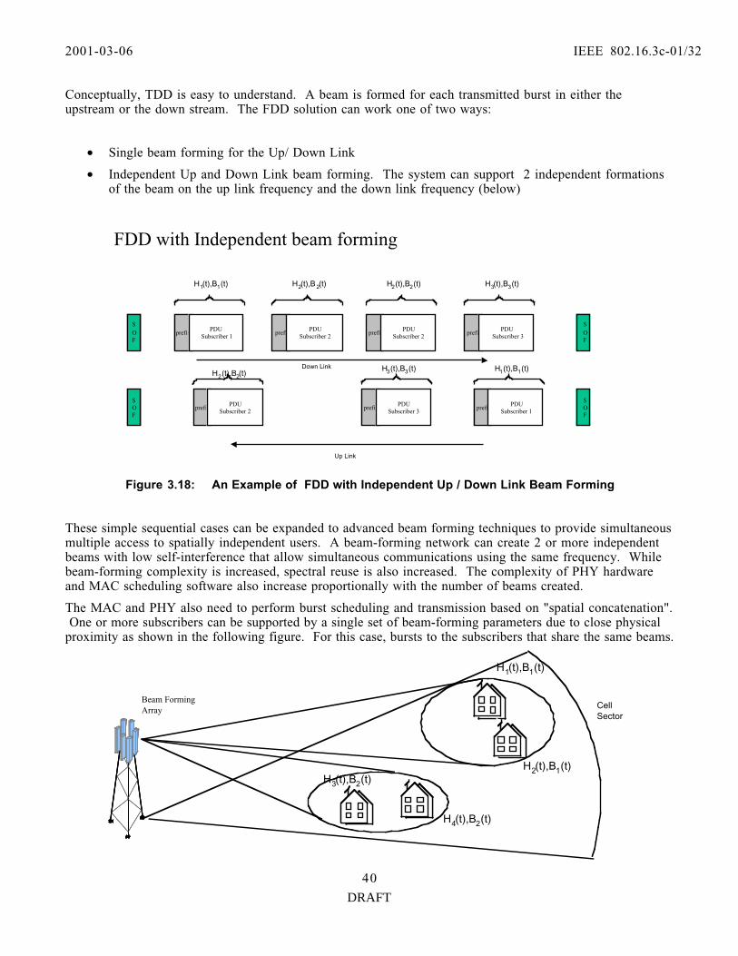
2001-03-06 IEEE 802.16.3c-01/32
DRAFT
40
Conceptually, TDD is easy to understand. A beam is formed for each transmitted burst in either theupstream or the down stream. The FDD solution can work one of two ways:
• Single beam forming for the Up/ Down Link
• Independent Up and Down Link beam forming. The system can support 2 independent formationsof the beam on the up link frequency and the down link frequency (below)
Down Link
prefixPDU
Subscriber 1
SOF
H1(t),B1(t)
SOF
prefixPDU
Subscriber 2
H2(t),B 2(t)
Up Link
prefixPDU
Subscriber 2
H2(t),B2(t)
prefixPDU
Subscriber 3
H3(t),B3(t)
FDD with Independent beam forming
SOF
SOF
prefixPDU
Subscriber 2
H2(t),B2(t)
prefixPDU
Subscriber 3
H3(t),B3(t)
prefixPDU
Subscriber 1
H1(t),B1(t)
Figure 3.18: An Example of FDD with Independent Up / Down Link Beam Forming
These simple sequential cases can be expanded to advanced beam forming techniques to provide simultaneousmultiple access to spatially independent users. A beam-forming network can create 2 or more independentbeams with low self-interference that allow simultaneous communications using the same frequency. Whilebeam-forming complexity is increased, spectral reuse is also increased. The complexity of PHY hardwareand MAC scheduling software also increase proportionally with the number of beams created.
The MAC and PHY also need to perform burst scheduling and transmission based on "spatial concatenation". One or more subscribers can be supported by a single set of beam-forming parameters due to close physicalproximity as shown in the following figure. For this case, bursts to the subscribers that share the same beams.
CellSector
H1(t),B1(t)
Beam FormingArray
H2(t),B1(t)H3(t),B2(t)
H4(t),B2(t)

2001-03-06 IEEE 802.16.3c-01/32
DRAFT
41
Figure 3.19: A Sectored Base Station Communicating with 4 Separate Subscribers in a SpatialConcatenated manner.
The following figure illustrates how packets are grouped (concatenated) and transmitted by based on physicalproximity for a TDD Physical layer.
Down Link
prefix PDUSubscriber 1
TX/RX Boundary
SOF
B1(t)
SOF
prefix PDUSubscriber 2
Up Link
prefix PDUSubscriber 3
B2(t)
prefix PDUSubscriber 4
TDD
Figure 3.20: An Example of TDD with Concatenated Packet transmissions.
The proposed PHY based on block processing and burst packet formats meets all therequirements to support advanced antenna processing techniques. As the standard progresses wemust address the following issues in greater detail:
• Beam forming Transition/ Set-up time definition in the MAC (passing parameters to PHY)
• Method for broadcasting Uplink and Downlink MAP information
• Acquisition methods and beam scanning
• Cell to Cell interference and C/I issues
• Spatial mutiplexing.
3.3 Single-Carrier with Frequency Domain Equalization (SC-FDE)Scheme2-11 GHz systems may operate on NLOS conditions, in which severe multi-path is encountered. Multi-path delay spread is a major transmission problem, which affects the design of modulation andequalization. Delay spread varies with environment and characteristics of transmit and receive antennas. In typical MMDS operating conditions, average delay spread ~ 0.5 µs, but 2% of measured delay
spreads > approx. 8-10 µs [15], [16], [17].
Single carrier modulation, with receiver linear equalization (LE) or decision feedback equalization(DFE) in frequency domain - approximately equal complexity to OFDM, without the power back-offpenalty [17], [18], [19] and [28].
Note that with an adaptive receiver based on Frequency Domain processing can handle both OFDM andSingle Carrier modulation.
2001-03-06 IEEE 802.16.3c-01/32
DRAFT
42
Further note that, Hikmet Sari in References [16 and 28 to 31] has significantly contributed to thedevelopment of Single Carrier modulation with Frequency Domain Equalization (SC-FDE). He alsointroduced the concept of Cyclic prefix to simplify the processing. However, there were few others (inthe 70 s and 80 s) in the field who have introduced the concept of Frequency Domain Equalizer withoverlap-add methods which can eliminate the need for a cyclic prefix but introduces added complexity inprocessing and adaptation. We should also mention that Sari [16] was the first to compare SC-FDEexplicitly with OFDM.
Furthermore note that OFDM itself existed in the 50’s and 60’s as part of some military HF modems.
3.3.1 Single Carrier-Frequency Domain Equalization (SC-FDE) and OFDM
OFDM transmits multiple modulated subcarriers in parallel. Each occupies only a very narrowbandwidth. Since only the amplitude and phase of each subcarrier is affected by the channel,compensation of frequency selective fading is done by compensating for each subchannel s amplitudeand phase. OFDM signal processing is carried out relatively simple by using two fast Fouriertransforms (FFT s), at the transmitter and the receiver, respectively.
The single carrier (SC) system transmits a single carrier, modulated at a high symbol rate. Frequencydomain equalization in a SC system is simply the frequency domain analog of what is done by aconventional linear time domain equalizer. For channels with severe delay spread it is simpler thancorresponding time domain equalization for the same reason that OFDM is simpler: because of the FFToperations and the simple channel inversion operation.
The main hardware difference between OFDM and SC-FDE is that the transmitter s inverse FFT blockis moved to the receiver. The complexities are the same. A dual-mode system could be designed tohandle either OFDM or SC-FDE by simply interchanging the IFFT block between the transmitter andreceiver at each end (see Figure 3.21.)
Both systems can be enhanced by coding (which is in fact required for OFDM systems), adaptivemodulation and space diversity. In addition, OFDM can incorporate peak-to-average reduction signalprocessing to partially (but not completely) alleviate its high sensitivity to power amplifiernonlinearities. SC-FDE can be enhanced by adding decision feedback equalization or maximum likelihoodsequence estimation.

2001-03-06 IEEE 802.16.3c-01/32
DRAFT
43
Figure 3.21- OFDM and Single Carrier-Frequency Domain Equalization (SC-FDE).
3.3.2 Compatibility of Single Carrier (SC-FDE) and OFDM
Comparable SC-FDE and OFDM systems would have the same block length and cyclic prefix lengths.Since their main hardware difference is the location of the inverse FFT, a modem could be converted asrequired to handle both OFDM and single carrier signals by switching the location of the inverse FFTblock between the transmitter and receiver. Therefore, the coexistence of OFDM and SC-FDE as aconvertible modem can be feasible (see Figure 3.22).
IFFT FFTCPIInvertchannel Detect
IFFTFFTCPIInvertchannel Detect
(a) OFDM :
(b) Single-Carrier Modulation (SC-FDE):
CPI: cyclic prefix insertionFFT: fast Fourier transformIFFT: inverse FFT
Transmitter
Transmitter
Receiver
Receiver

2001-03-06 IEEE 802.16.3c-01/32
DRAFT
44
Figure 3.22 - OFDM and SC-FDE Convertible Modem Approach.
Figure 3.23 - Block Processing in Frequency Domain Equalization
As shown in Figure 3.23, that the cyclic prefix used in both SC-FDE and OFDM systems at thebeginning of each block has two main functions:
• It prevents contamination of a block by intersymbol interference from the previous block.
• It makes the received block appear to be periodic with period M, which is essential to the properfunctioning of the fast Fourier transform operation.
If the first U and last U symbols are identical unique word sequences of training symbols, the overheadfraction is 2U / (N+U).
For either OFDM or SC-FDE MMDS systems, typical values of N could be 512 or 1024, and typicalvalues of U could be 64 or 128.
Transmitter
FFT
CPI
Invertchannel Detect
Receiver
IFFT
IFFT
To channel
From channel
IFFT switched to transmitter for OFDM, switched toreceiver for SC-FDE
Last Usymbolsrepeated
Usymbols
Block of N data symbols
Cyclicprefix

2001-03-06 IEEE 802.16.3c-01/32
DRAFT
45
3.4 The frequency range and the channel bandwidthThe frequency range and the downstream and upstream channel bandwidth of the Proposed PHY system aregiven in Table 3.5.
Table 3.5: Frequency Bands and Channel Bandwidth
Frequency Bands
Channel Bandwidth Options Reference
2.15- 2.162 GHz,
2.50- 2.690 GHz
2 to 6 MHz downstream,
200 kHz to 6 MHz upstream
FCC 47 CFR 21.901 (MDS)
FCC 47 CFR 74.902 (ITFS, MMDS)
Industry Canada SRSP-302.5 (FixedServices operating in the 2500 to 2686MHz band)
b) 3.5 GHz 1.75- 7 MHz downstream,
250 KHz to 7 MHz upstream
EN 301 021,
CEPT/ERC Rec. 14-03 E, CEPT/ERCRec. 12-08 E, Others (TBD)
c) 10.5 GHz 3.5, 5 and 7 MHz EN 301 021, CEPT/ERC Rec. 12-05 E
3.5 Duplex SchemesIn order to comply with the IEEE802.16.3 fuctional requirement [1], we propose to support TDD, FDD and Half-Duplex mode systems and leave the selection of each system to the vendors /operators decision onimplementation complexity, traffic scenario, cost objectives and spectrum availability.
3.5.1 TDD:In Time division duplex (TDD) systems, the radio frame is divided into a downlink and an uplink section,offering flexibleand dynamic allocation of the upstream and downstream capacity. TDD enables the use ofsimpler antennas. In BWA system, where the delay between transmission and reception can consist of a fewtime slots, a guard time between the downlink and uplink sections of the frames has to be introduced in orderto avoid collision between time slots. However, the guard time reduces system throughput, especially if thesystem is designed for low latency.
3.5.2 FDD:In Frequency division duplex (FDD) systems, on the other hand, allocate a fixed proportion betweenuplink and downlink capacity. Residential users are likely to request asymmetrical uplink and downlinkcapacity, while in a business-user scenario, more symmetrical traffic behavior is likely to be the rule. FDDsystem can have full flexibility for instantaneous capacity allocation in the uplink and downlink for eachaccess terminal and connection and it can address the business market segment easily.

2001-03-06 IEEE 802.16.3c-01/32
DRAFT
46
3.6 Downstream Channel
3.6.1 Downstream Multiple Access SchemeEach downstream RF channel (e.g., 6 MHz wide) is subdivided into fixed frames with which the RF carrier issuitability modulated (e.g., QPSK, 16 QAM or 64 QAM) to provide a digital bit stream (e.g., 10 to 30 Mbps). Within each RF channel a frame structure is used to organize and schedule the transmission of voice, videoand data traffic.
3.6.2 Modulation SchemesThe applicable modulation schemes for the downstream are QPSK, 16 QAM or 64 QAM.
Adaptive Modulation & Coding shall be supported in the downstream. The upstream shall supportdifferent modulation schemes for each user based on the MAC burst configuration messages coming from theBase Station. Complete description of the MAC / PHY support of adaptive modulation and coding isprovided in Section 3.2.
3.6.3 Downstream Randomization, Channel Coding & Interleaving, SymbolMapping and Baseband Shaping
The downstream channel supports various modulation formats and FEC coding on the user data portion ofthe frame. Different modulation formats and FEC groups can be defined on a subscriber level basis. In thisway the downstream channel supports adaptive modulation and coding. Note that each frame containscontrol portion with fixed modulation (QPSK) and FEC scheme. The details are described in FramingSection.
3.6.3.1 Randomization for Spectrum ShapingPrior to FEC encoding, the downstream channel will be randomized to ensure sufficient bit transitions tosupport clock recovery and to minimize occurrence of unmodulated carrier frequency. This process is doneby modulo—2 addition (XORing) the data with the output of Linear-Feedback Shift Register (LFSR) withcharacteristic polynomial 1 + X14 + X15. The LFSR is cleared and preset at the beginning of each burst to aknown value—100101010000000.
The preambles are not randomized and only information bits are randomized. The LFSR sequence generatorpauses while parity bits are being transmitted.
3.6.3.2 Downstream Channel FEC definitionsConsistent with the structure of the 802.16 MAC, forward error correction code schemes which support bothBlock Turbo Coding and Concatenated Reed-Solomon+Convolutional coding will be employed. In addition,the provision of suppressing all FEC and operating using the ARQ mechanism in the 802.16 MAC for errorcontrol will be included.
Following is the summary of these coding schemes:
Block Turbo Code: This type of coding is based on the product of two or more simple component codes(also called Turbo Product code, TPC). The decoding is based on the concept of Soft-in/Soft-out (SISO)iterative decoding (i.e, Turbo decoding ). The component codes recommended for this proposal are binaryextended Hamming codes or Parity check codes. The schemes supported follow the recommendation of theIEEE802.16.1 mode B. However, more flexibility in block size and code rates is enabled. The main benefitsof using BTC mode, are typically 2 dB better performance over the Concatenated RS, and shorter decodingdelays. A detailed description of Block Turbo Coding is included as Appendix C.

2001-03-06 IEEE 802.16.3c-01/32
DRAFT
47
Concatenated Reed-Solomon+Convolutional code: This case is based on concatenation of outer codingRS (204,188, t=8) and inner rate _ Convolutional code with constraint length K=7. The Convolutional codeis able to be configured to code rates 2/3, _, 5/6 and 7/8 using puncturing Convolutional interleaving withdepth I=12 shall be implied as described in DVB-S spec [13]. The detailed description of Concatenated Reed-Solomon Coding is included as Appendix C.
3.6.3.3 Symbol MappingThe mapping of bits into I and Q axes will be Gray-coded and for Reed-Solomon codes is pragmatic that aredescribed in Ref [26] for all constellations.
3.6.3.4 Baseband Pulse ShapingPrior to modulation, I and Q signals shall be filtered by square-root raised cosine. The roll-off factor α shallbe either 0.15 or 0.25. The ideal square-root cosine is defined by the following transfer function H(f):
Where:
fN is the Nyquist frequency, and Ts is modulation symbol duration.
3.7. UpStream Channel
3.7.1 Upstream Multiple Access
The upstream multiple access method shall be TDMA.
The upstream channel bandwidth for MMDS channel allocation would be 6MHz. In TDD mode this6MHz bandwidth can be dynamically allocated. This TDD flexibility permits efficient allocation of theavailable bandwidth and hence is capable of efficiently allocating the available traffic transport capacityfor applications whose upstream to downstream traffic transport demand ratio can vary with time. FDD can be used by applications that require fixed asymmetric allocation between their upstream anddownstream traffic transport demand. In FDD mode upstream traffic would typically be allocated3MHz. This is half of the 6MHz bandwidth assuming symmetrical traffic requirements.
}
)1(||0)(
)1(||)1(||
2sin
2
1
2
1)(
)1(||1)(
2/1
α
ααα
π
α
+≥=
+≤≤−
−
+=
−⟨=
N
NNN
N
N
ffforfH
fffforff
ffH
ffforfH
22
1 S
S
N
R
Tf ==

2001-03-06 IEEE 802.16.3c-01/32
DRAFT
48
3.7.2 Upstream Modulation Format
The upstream modulation types can be the same as those available for downstream transmission; e.g.,QPSK, 16QAM, or 64QAM. Modulation type, error correction, interleaving, etc, can be assigned to theupstream traffic for a particular Subscriber Station (SS) such that these parameters can be the same as inthe downstream burst received by the SS. The SS accesses the ’quality’ of the received signal from thedownstream header, and the SS MAC decides on the best modulation and error correction to use for thechannel conditions. This information is passed back up to the Access Point (AP) in the correspondingupstream burst, and the AP MAC uses this information to assign the modulation type and errorcorrection to the next burst of data to be transmitted.
3.7.3 Upstream Randomization, Channel Coding & Interleaving, SymbolMapping And Baseband Shaping
The upstream channel has processing units similar to those described for the downstream. However,greater flexibility in packet transmission is allowed. The subscriber stations are transmitting only afterreceiving some configuration information from the base station through MAC messages. Severaldifferent configurations can be adjusted on the upstream channel on a burst-to-burst basis. Theupstream payload is segmented into blocks of data designed to fit into the proper codeword size(including Transmission Convergence sublayer, TC, header). Note that payload length may vary fromburst to burst.
3.7.3.1 Randomization for Spectrum Shaping
The upstream modulator uses a randomizer using LFSR with connection polynomialX15 + X14 +1, with a 15-bits programmable seed. At the beginning of each burst, the register is clearedand the seed value is loaded. The seed value is used to calculate the scrambler output bit, obtained as theXOR of the seed with first bit of DATA of each burst (which is the MSB of the first symbol followingthe last symbol of the preamble).
3.7.3.2 FEC schemes for the upstream channel
Consistent with the structure of the 802.16 MAC forward error correction code schemes which supportboth Block Turbo Coding (TPC) and Concatenated Reed-Solomon+Convolutional coding will beemployed. In addition, the provision of suppressing all FEC and operating using the ARQ mechanism inthe 802.16 MAC for error control will be included.
3.7.3.3 Interleaving for the upstream channel
Interleaving is applied for the upstream channel only with BTC FEC scheme.
3.7.3.4 Baseband Pulse Shaping
Prior to modulation, the I and Q signals shall be filtered by square-root raised cosine. The roll-off factor α shall be either 0.15 or 0.25. The ideal square-root cosine is defined by the following transfer functionH(f):
2001-03-06 IEEE 802.16.3c-01/32
DRAFT
49
Where:
fN is the Nyquist frequency, and Ts is modulation symbol duration.
3.8 System Capacity and Modulation EfficiencyTable 7 shows the BWA PHY with Downstream and Upstream modulation schemes and the correspondingsystem capacity and Bits per sec./ Hz. The aggregate transmission bit rate is optimized based on severalconstraints. These are:
• The allocated channel bandwidth;
• The modulation level;
• The spectrum shaping filter bandwidth with roll factor of _ = %0.15 or %0.25;
• The FEC coding scheme (Reed-Solomon (n, k) over GF(28));
• The requirement of upstream time tick for the Mini-slots burst duration; and
• Processing power limitation of available chips to be used.
}
)1(||0)(
)1(||)1(||
2sin
2
1
2
1)(
)1(||1)(
2/1
α
ααα
π
α
+≥=
+≤≤−
−
+=
−⟨=
N
NNN
N
N
ffforfH
fffforff
ffH
ffforfH
22
1 S
S
N
R
Tf ==
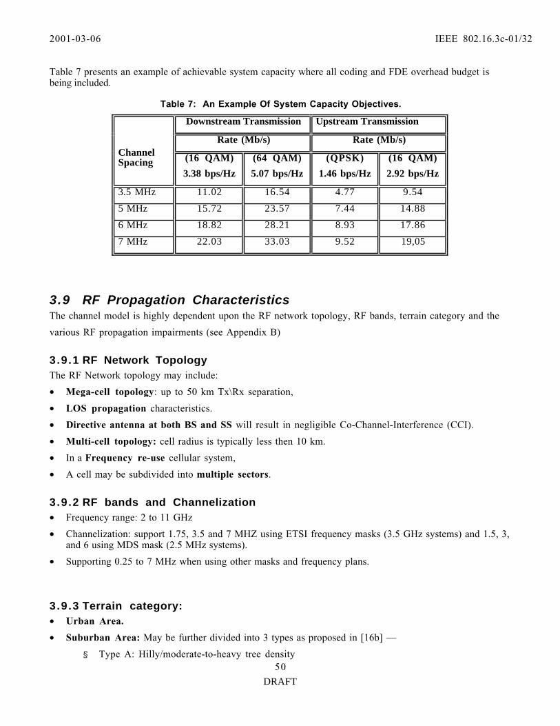
2001-03-06 IEEE 802.16.3c-01/32
DRAFT
50
Table 7 presents an example of achievable system capacity where all coding and FDE overhead budget isbeing included.
Table 7: An Example Of System Capacity Objectives.
Downstream Transmission Upstream Transmission
Rate (Mb/s) Rate (Mb/s)ChannelSpacing (16 QAM)
3.38 bps/Hz
(64 QAM)
5.07 bps/Hz
(QPSK)
1.46 bps/Hz
(16 QAM)
2.92 bps/Hz
3.5 MHz 11.02 16.54 4.77 9.54
5 MHz 15.72 23.57 7.44 14.88
6 MHz 18.82 28.21 8.93 17.86
7 MHz 22.03 33.03 9.52 19,05
3.9 RF Propagation CharacteristicsThe channel model is highly dependent upon the RF network topology, RF bands, terrain category and the
various RF propagation impairments (see Appendix B)
3.9.1 RF Network TopologyThe RF Network topology may include:
• Mega-cell topology: up to 50 km Tx\Rx separation,
• LOS propagation characteristics.
• Directive antenna at both BS and SS will result in negligible Co-Channel-Interference (CCI).
• Multi-cell topology: cell radius is typically less then 10 km.
• In a Frequency re-use cellular system,
• A cell may be subdivided into multiple sectors.
3.9.2 RF bands and Channelization• Frequency range: 2 to 11 GHz
• Channelization: support 1.75, 3.5 and 7 MHZ using ETSI frequency masks (3.5 GHz systems) and 1.5, 3,and 6 using MDS mask (2.5 MHz systems).
• Supporting 0.25 to 7 MHz when using other masks and frequency plans.
3.9.3 Terrain category:• Urban Area.
• Suburban Area: May be further divided into 3 types as proposed in [16b] —
§ Type A: Hilly/moderate-to-heavy tree density

2001-03-06 IEEE 802.16.3c-01/32
DRAFT
51
§ Type B: Hilly/light tree density or flat/moderate-to-heavy density
§ Type C: Flat/Light tree density.
3.9.4 RF propagation impairments:• Path Loss
• Fading (large scale — due to shadowing, small scale- due to multi-path).
• CCI and ACI
• Worst case fading bandwidth and maximum Doppler shift.
3.9.5 Minimum Performance SpecificationsBased on the measurements given in Appendix B the channel model must meet the following requirements:Maximum time delay spread of 12 µsec. The system should withstand a Doppler shift of more then 10 Hz.
3.10 Antenna Systems
3.10.1 Application of Smart Antenna
The PHY layer shall support future application of smart antenna for primary feature of providing theability to track the line of sight target within a predetermined angle of uncertainty. Typically, one wouldexpect 3 or more degrees of tracking. This active tracking capability of smart antenna will potentiallyprovide better coexistence and will optimize the antenna pattern (transmit where the subscriber islocated)
3.10.2 Antenna Diversity
Multiple antennas can be used at the transmitter and/or receiver to provide added dimension to themodel.
When multiple antenna diversity (so called Multiple-Input/Multiple-Output; MIMO) is compared witha Single-Input/Single-Output (called SISO) technique, it is shown in performance that it can improve thecapacity of the fading wireless channel regardless of the modulation techniques utilized. It is applicableto Single Carrier (SC) modulation. The benefits, however, of using space diversity should be examinedagainst its implementation complexity and economic factors.
4.0 Comparative Analysis of OFDM vs SC- FDE:
Multi-carrier techniques like OFDM split a high-rate data-stream into a number of lower rate streamsthat are transmitted simultaneously over several sub-carriers. That is, creating several parallel narrow-band sub-channels. Therefore, while the symbol duration increases for the lower rate parallel subcarriers,the relative amount of dispersion in time caused by multipath delay spread is decreased. Intersymbol

2001-03-06 IEEE 802.16.3c-01/32
DRAFT
52
interference (ISI) is eliminated almost completely by introducing a guard time in every OFDM symbol. In the guard time, the OFDM symbol is cyclically extended to avoid Intercarrier interference (ICI) [3].With OFDM a number of parameters are up for consideration, such as;
• the number of subcarriers,
• guard time,
• symbol duration, subcarrier spacing, modulation type per carrier, and
• the type of FEC coding.
It has been shown that OFDM systems offer no advantages over Single Carrier modulation forms insevere multipath — see [21], [22], [23], and [24]. In particular [21] compares the performance of a codedOFDM signal in multipath environments and shows that single carrier systems offer superiorperformance in all but a very limited number of cases. In addition, in Section 4.1, we will present someof the results that will appear in [20] showing that Single Carrier with Frequency Domain Equalizer(SC—FDE) techniques can outperform OFDM in performance when the channels of communicationsuffer from deep multi-path fading in addition to the usual AWGN noise.
In a Single-Carrier system, the implementation complexity is dominated by the requirement ofequalization, which is necessary when the delay spread is larger than about 10% of the symbol duration. In OFDM, the equalization is done by amplitude and phase-correction of each subchannel. Thecomplexity of both modulation systems can largely be determined by FFT and inverse FFTrequirements. This complexity in fact can be reduced by not requiring full multiplication, but ratherphase rotations, which can be efficiently implemented by the CORDIC algorithm [3]. In fact, thetechnology is advancing rather rapidly in this area.
We should emphasize that OFDM imposes stricter constraints on the analog blocks due to its largePeak-to-Average Power Ratio (PAPR) characteristics and its sensitivity to carrier frequency offset andphase noise. Thus, to alleviate the time-varying frequency offsets between transmitter and receiver mustuse an accurate AFC circuitry, otherwise the sub-carriers will no longer be orthogonal. Synchronizationof a multi-carrier scheme is much more difficult than a single carrier system. In addition, OFDM with alarge number of sub-carriers, the combined signal has a very large PAPR and to maintain linearity overthe range, the power amplifier will require back-off by as much as 10dB [7].
4.1 Proposed System Robustness
4.1.1 Performance in a Fading Channel
The performance of both the SC and OFDM modes of this proposal has been evaluated via extensiveMonte Carlo simulation.

2001-03-06 IEEE 802.16.3c-01/32
DRAFT
53
4.1.1.1 Simulation Assumptions:
¥ Monte Carlo BER performances of SC Frequency Domain Equalizers and OFDM over multipathfading channels are as follows:
¥ Frequency domain linear equalizer (FD-LE)
¥ Frequency domain decision feedback equalizer (FD-DFE) with infinite-length feedback filterand correct feedback (i.e., no decision errors)
¥ Matched filter bound (MFB), a benchmark performance for all systems
¥ OFDM with linear equalization.
¥ Channel Model: SUI5 and SUI2 (Vinko et al., Feb 2001). No diversity.
¥ Coding: Bit Interleaved Coded Modulation (BICM) using a rate 1/2 Convolutional code with aconstraint length of K=7 and generator polynomials (133, 171). Each data block contains 512 codedQPSK symbols. Bit-by-bit interleaving within each block, using a block with an interleaver depth of16*k, where k= log2M, and M is the number of modulation levels, is assumed for both SC and OFDM. The log a posteriori probability (APP) of each bit is used as the soft input to the decoder.
¥ The rate 7/8 code is obtained by puncturing the output of the rate 1/2 encoder with a constraintlength of K=7. An optimal puncturing pattern is used [35].
¥ Simulation Conditions: QPSK with 0.1 roll-off, 20,000 fading channel realizations, 512 point FFT,quasi-static fading, no channel estimation errors. For each channel realization, analytical MMSEoutput SNR of each receiver is computed and used to generate an equivalent Gaussian noise channelfor BER simulation.

2001-03-06 IEEE 802.16.3c-01/32
DRAFT
54
Figure 4.1: SC-FDE and OFDM Performance over SUI Channel # 5 (Coded Rate _ and noDiversity)
SUI5, 1 Rx ant., rate 1/2 conv. codeQPSK, roll-off = 0.1
1.E-06
1.E-05
1.E-04
1.E-03
1.E-02
1.E-01
1.E+00
0 5 10 15 20 25 30
Average SNR
Ave
rage
BE
RFD-LE
FD-DFE
MFB
OFDM
SUI5 (omni), 1 Rx ant., rate 7/8 conv. codeQPSK, roll-off = 0.1
1.E-06
1.E-05
1.E-04
1.E-03
1.E-02
1.E-01
1.E+00
0 5 10 15 20 25 30
Average SNR
Ave
rage
BE
R
FD-LE
FD-DFE
MFB
OFDM

2001-03-06 IEEE 802.16.3c-01/32
DRAFT
55
Figure 4.2: SC-FDE and OFDM Performance over SUI Channel # 5 (Coded Rate 7/8 and noDiversity)
Figure 4.3: SC-FDE and OFDM Performance over SUI Channel # 5 (Coded Rate 1/2 and with 4,16, 64-QAM)
SUI5 (omni), 1 Rx ant., rate 1/2 conv. codeQPSK, 16QAM, 64QAM, roll-off = 0.1
1.E-06
1.E-05
1.E-04
1.E-03
1.E-02
1.E-01
1.E+00
0 5 10 15 20 25 30 35
Average SNR
Ave
rage
BE
R
FD-LE
FD-DFE
MFB
OFDM
SUI5 (omni), 1Tx-2 Rx ant., rate 7/8 conv. code64QAM, roll-off = 0.1
1.E-06
1.E-05
1.E-04
1.E-03
1.E-02
1.E-01
1.E+00
0 5 10 15 20 25 30
Average SNR
Ave
rage
BE
R
FD-LE
FD-DFE
MFB
OFDM

2001-03-06 IEEE 802.16.3c-01/32
DRAFT
56
Figure 4.4: SC-FDE and OFDM Performance over SUI Channel # 5 (Coded Rate 7/8 and 2 RXdiversity)
Figure 4.5: SC-FDE and OFDM Performance over SUI Channel # 5 (Coded Rate 7/8 and 2 Tx, 2RX Diversity and 64-QAM)
SUI5, 1Tx-2 Rx ant., rate 3/4 conv. code64QAM, roll-off = 0.1
1.E-06
1.E-05
1.E-04
1.E-03
1.E-02
1.E-01
1.E+00
0 5 10 15 20 25 30
Average SNR
Ave
rage
BE
RFD-LE
FD-DFE
MFB
OFDM
SUI5 (omni), 2Tx-2 Rx ant., rate 7/8 conv. code64QAM, roll-off = 0.1
1.E-06
1.E-05
1.E-04
1.E-03
1.E-02
1.E-01
1.E+00
0 5 10 15 20 25 30
Average SNR
Ave
rage
BE
R
FD-LE
FD-DFE
MFB
OFDM
SUI2 (omni), 2Tx-2 Rx ant., rate 7/8 conv. code64QAM, roll-off = 0.1
1.E-06
1.E-05
1.E-04
1.E-03
1.E-02
1.E-01
1.E+00
0 5 10 15 20 25 30
Average SNR
Ave
rage
BE
R
FD-LE
FD-DFE
MFB
OFDM
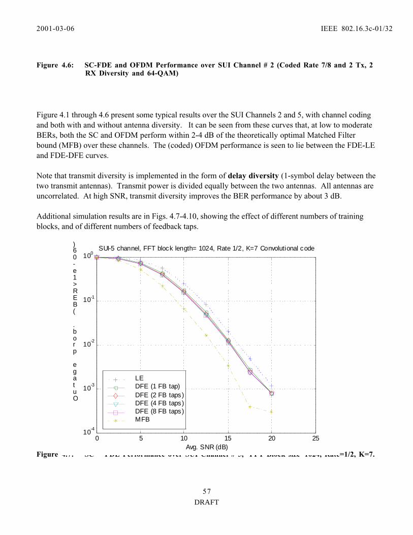
2001-03-06 IEEE 802.16.3c-01/32
DRAFT
57
Figure 4.6: SC-FDE and OFDM Performance over SUI Channel # 2 (Coded Rate 7/8 and 2 Tx, 2RX Diversity and 64-QAM)
Figure 4.1 through 4.6 present some typical results over the SUI Channels 2 and 5, with channel codingand both with and without antenna diversity. It can be seen from these curves that, at low to moderateBERs, both the SC and OFDM perform within 2-4 dB of the theoretically optimal Matched Filterbound (MFB) over these channels. The (coded) OFDM performance is seen to lie between the FDE-LEand FDE-DFE curves.
Note that transmit diversity is implemented in the form of delay diversity (1-symbol delay between thetwo transmit antennas). Transmit power is divided equally between the two antennas. All antennas areuncorrelated. At high SNR, transmit diversity improves the BER performance by about 3 dB.
Additional simulation results are in Figs. 4.7-4.10, showing the effect of different numbers of trainingblocks, and of different numbers of feedback taps.
Figure 4.7: SC —FDE Performance over SUI Channel # 5, FFT Block size=1024, Rate=1/2, K=7.
0 5 10 15 20 2510
-4
10-3
10-2
10-1
100
Avg. SNR (dB)
Outage prob. (BER>1e-06)
SUI-5 channel, FFT block length= 1024, Rate 1/2, K=7 Convolutional code
LEDFE (1 FB tap)DFE (2 FB taps)DFE (4 FB taps)DFE (8 FB taps)MFB
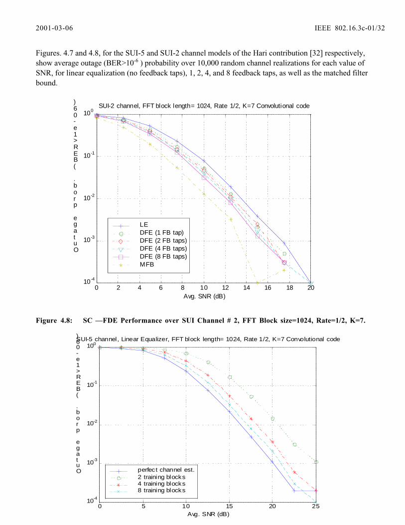
2001-03-06 IEEE 802.16.3c-01/32
DRAFT
58
Figures. 4.7 and 4.8, for the SUI-5 and SUI-2 channel models of the Hari contribution [32] respectively,show average outage (BER>10-6 ) probability over 10,000 random channel realizations for each value ofSNR, for linear equalization (no feedback taps), 1, 2, 4, and 8 feedback taps, as well as the matched filterbound.
Figure 4.8: SC —FDE Performance over SUI Channel # 2, FFT Block size=1024, Rate=1/2, K=7.
0 2 4 6 8 10 12 14 16 18 2010-4
10-3
10-2
10-1
100
Avg. SNR (dB)
Outage prob. (BER>1e-06)
SUI-2 channel, FFT block length= 1024, Rate 1/2, K=7 Convolutional code
LEDFE (1 FB tap)DFE (2 FB taps)DFE (4 FB taps)DFE (8 FB taps)MFB
0 5 10 15 20 2510-4
10-3
10-2
10-1
100
Avg. SNR (dB)
Outage prob. (BER>1e-06) SUI-5 channel, Linear Equalizer, FFT block length= 1024, Rate 1/2, K=7 Convolutional code
perfect channel est.2 training blocks4 training blocks8 training blocks

2001-03-06 IEEE 802.16.3c-01/32
DRAFT
59
Figure 4.9: SC —LE Performance over SUI Channel # 5, FFT Block size=1024, Rate=1/2, K=7.
Figure 4.10: SC —FDE with 1 Feedback tap, Performance over SUI Channel # 5, FFT Blocksize=1024, Rate=1/2, K=7.
Figures. 4.9 and 4.10, for SUI channel 5, show the outage performance as a function of the number oftraining blocks, for linear frequency domain equalization and 1-tap decision feedback frequency domainequalization respectively. Here, a training block is a 64-symbol Frank sequence. Averaging over 2, 4 or8 training blocks gives an estimate of the channel s frequency response for a 64-symbol FFT block. Thefigures include the effect of interpolating this 64-symbol frequency domain estimate to a 1024-symbolFFT block length.
4.1.1.2 Summary of the above comparative results:
The results presented in this section enable us to conclude that Frequency Domain Processing(Figures 4.1 to 4.10) is, in general, an extremely robust technique to counter the frequency-selectivefading effects of channels with severe delay spread.
OFDM is sensitive to high code rates (i.e., Rate > _).
0 5 10 15 20 2510
-4
10-3
10-2
10-1
100
Avg. SNR(dB)
Outageprob.(BER>1e-06)forQPSK
SUI-5 channel, DFE Equalizer with 1 Feedback Tap, FFT block length= 1024, Rate 1/2, K=7Convolutional code
perfect channelest.2 trainingblocks4 trainingblocks8 trainingblocks

2001-03-06 IEEE 802.16.3c-01/32
DRAFT
60
The FD-DFE achieves a universally superior performance, with substantial gains evident by using evena few (1-2) feedback taps. One feedback tap is sufficient (up to 8 taps gives little additionalimprovement). 1 tap gives 1-4 dB gain over linear equalizer.
Performances for SUI-2 and SUI-5 are similar (slightly better for SUI-5 because of the higher degree offrequency selectivity). In fact, the results for all receivers perform slightly worse in SUI 2 than in SUI 5.
With diversity, OFDM performs slightly (about 1 dB) better than FD-LE, but ideal FD-DFE performsuniversally better than OFDM by up to 3 dB. Transmit diversity improves the BER performance byabout 4 dB.
In the uncoded case, FD-DFE outperforms FD-LE by about 2 to 4 dB (at BER below 0.001) withoutdiversity. The gap increases with average SNR because of the noise enhancement effect. Conversely,
4.1.2 Impact of Phase Noise
An exact closed form expression relating the combined phase noise performance of a set of oscillatorsused for the frequency translation of a received QAM signal, and their effects on the BER of thedemodulated product, is very hard to determine. One obstacle is the fact that an exact analyticalrepresentation of phase behavior that considers all of the noise processes in each oscillator is extremelycomplicated. An additional impediment is that there is no exact input/output relationship for theprocessed phase noise as it travels through amplifiers, PLLs, downconverters and other blocks. Therefore the results that follows are based on empirical data and basic analytical models of phase noiseand frequency synthesis/translation.
Total RMS phase error for a dual-conversion, MMDS band receiver has been determined to be as shownin Figure 4.11. This receiver was designed utilizing low cost silicon technology with an inexpensiveTCXO as the reference for the LO synthesizers.
Total Phase Error
0
0.2
0.4
0.6
0.8
1
1.2
0.1 1 10 100Track er Loop BW (KHz)
Ph
ase
Err
or
(deg
. rm
s)
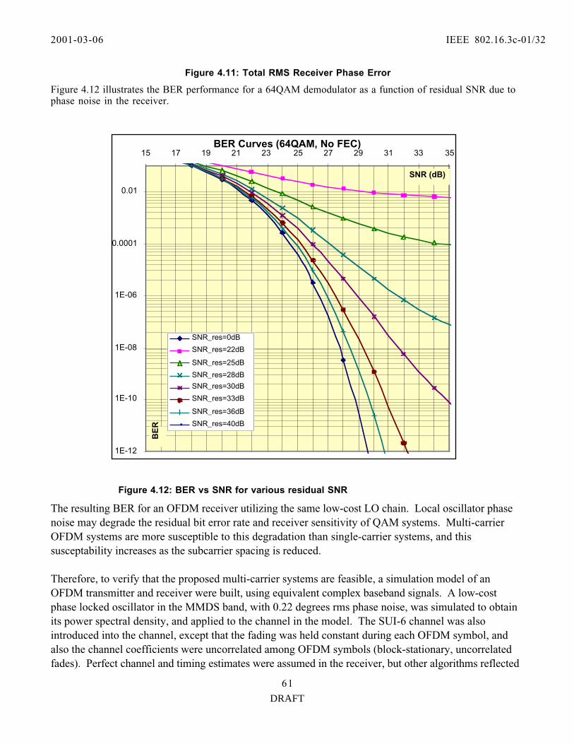
2001-03-06 IEEE 802.16.3c-01/32
DRAFT
61
Figure 4.11: Total RMS Receiver Phase Error
Figure 4.12 illustrates the BER performance for a 64QAM demodulator as a function of residual SNR due tophase noise in the receiver.
Figure 4.12: BER vs SNR for various residual SNR
The resulting BER for an OFDM receiver utilizing the same low-cost LO chain. Local oscillator phasenoise may degrade the residual bit error rate and receiver sensitivity of QAM systems. Multi-carrierOFDM systems are more susceptible to this degradation than single-carrier systems, and thissusceptability increases as the subcarrier spacing is reduced.
Therefore, to verify that the proposed multi-carrier systems are feasible, a simulation model of anOFDM transmitter and receiver were built, using equivalent complex baseband signals. A low-costphase locked oscillator in the MMDS band, with 0.22 degrees rms phase noise, was simulated to obtainits power spectral density, and applied to the channel in the model. The SUI-6 channel was alsointroduced into the channel, except that the fading was held constant during each OFDM symbol, andalso the channel coefficients were uncorrelated among OFDM symbols (block-stationary, uncorrelatedfades). Perfect channel and timing estimates were assumed in the receiver, but other algorithms reflected
BER Curves (64QAM, No FEC)
1E-12
1E-10
1E-08
1E-06
0.0001
0.01
15 17 19 21 23 25 27 29 31 33 35
SNR (dB)
BE
R
SNR_res=0dB
SNR_res=22dB
SNR_res=25dB
SNR_res=28dB
SNR_res=30dB
SNR_res=33dB
SNR_res=36dB
SNR_res=40dB
2001-03-06 IEEE 802.16.3c-01/32
DRAFT
62
the operation of an actual OFDM receiver. Simulations were run using several representative sets ofmult-carrier OFDM system parameters.
As expected, the oscillator phase noise introduced residual noise into the equalized receiver FFToutputs. The ratio of signal to residual noise power (SINR) was averaged over several tens of symbolsand found to be better than 44 dB in all cases. This noise level will cause negligible sensitivitydegradation of a 64QAM receiver. Final results on phase noise complexity will be provided later on.
4.2 Amplifier Linearity Requirements
One of the most significant contributors to the cost of a BWA radio is the power amplifier (PA). Thefollowing simulation data was generated to determine the linearity requirements for a PA with singlecarrier versus multi-carrier modulation in order to better understand the impact of eithermodulation scheme or radio cost.
Model Assumptions:
The data presented below was generated based on a PA model derived from empirical measurements ofthe AM-AM and AM-PM characteristics of a +30 dBm P1dB, HBT PA operating at 2.5GHz. Themodel used in these simulations is a 5th order polynomial curve-fit of the empirical data.
Figure 4.4 shows the output of a GaAs power amplifier stage driven by a 64QAM signal. The output iscompliant with the spectral mask defined in 47CFR21.908 that defines the characteristics of 2.5 GHzMMDS transmitters. The amplifier is operated at approximately 9 dB below its rated 1dB compressedoutput power.

2001-03-06 IEEE 802.16.3c-01/32
DRAFT
63
Figure 4.13: Less back-off required to meet ACPR mask (64 QAM at 9 dB back off)
FCC Mask
Modulation Scheme: 64QAMSymbol Rate = 5Msps,Excess BW a=0.25,Nonlinearity model is tanh( ), Simulation length = 5000bits,Backoff values are -3, -6, -9, -12, -15dB

2001-03-06 IEEE 802.16.3c-01/32
DRAFT
64
Figure 4-14: OFDM at various back-ff levels
Figure 4.13 shows the simulated output of a similar GaAs power amplifier driven with a 1023 toneOFDM signal with 64 QAM modulation. The FCC mask is shown by the dotted line and the inabilityto comply with the FCC mask at even 12 dB back-off is apparent. The accuracy of the commonlygiven value of 14 dB back-off for compliance with the FCC mask is evident in Figure 4.13.
0 1 2 3 4 5 6
x 106
-60
-50
-40
-30
-20
-10
0
Frequency (Hz)
OFDM (64QAM,1023subcarriers) spectrum regrowth due to clipping: real PA model
FCC mask
Total subcarrier # = 1023 Used 885 subcarriers (skip 69 at each end) 64QAM, RC windowing with alpha = 0.1 FFT size = 4096 (x4 upsampling)
PA backoff
6dB 7dB 9dB 12dB
Amplifier input

2001-03-06 IEEE 802.16.3c-01/32
DRAFT
65
Figure 4.15: Power Distribution PDF
Figure 4.15 shows a PDF (probability distribution function) of the instantaneous power of the inputsignal to the PA. This plot shows that at 10-4 probability, there is approximately 4 dB more energy withan OFDM waveform as opposed to a single carrier 16QAM waveform.
The OFDM waveform plot was windowed with a raised cosine roll-off factor of alpha = 0.1. For the1024 subcarrier case we use a 4096 point FFT and eliminate 138 subcarriers to allow for some guard-band. The data is presented with the FCC MMDS spectral mask superimposed as a reference.
In Figures 4.16 and 4.17, are the latest simulation results for OFDM systems with 256 FFT and QPSK andwith 2048 FFT size and 16QAM, respectively. The results are for a 1.5 MHz bandwidth and 1.25 MHzsample frequency. Also, a Chebychev channel filter was inserted in the signal path for both systems.
0 2 4 6 8 10 12 10 -5
10 -4
10 -3
10 -2
10 -1
PAR (dB)
Probability Density of PAR
SCQAM and OFDM Peak-to-Average Ratio Comparison for 6 MHz Channel
64QAM 0.1 = red 0.2 = green
Fsymbol = 5MHz
16QAM 0.1 = blue 0.2 = cyan
QPSK 0.1 = black 0.2 = magenta
Constellation & RC filter rolloff
OFDM 256 FFT = cyan 512 FFT = blue 1024 FFT = red
SCQAM

2001-03-06 IEEE 802.16.3c-01/32
DRAFT
66
Figure 4.16: Signal Spectrum with FCC Mask for 256FFT block, QPSK and 9 dB P1dB Back-offfor OFDM.

2001-03-06 IEEE 802.16.3c-01/32
DRAFT
66
Figure 4.17: Signal Spectrum with FCC Mask for 2048FFT block, 16QAM and 9 dB P1dB Back-off for OFDM.
The above two simulation results are for two different constellations for OFDM systems and both at 9dB P1dB back-off amplifier. As we can see from the results the OFDM system can barely meet theFCC spectral mask at 9 dB back-off amplifier for QPSK. And for 16 QAM it exceeds the mask. So far,based on many other simulation results obtained, it appears that the difference in PA back-offrequirement for OFDM versus SC-FDE can be in the range of 6 - 9 dB higher.
Please note that the OFDM data does not take into consideration any algorithms to reduce PAP, it isbasically the raw data. Clearly this is an area for further analysis.

2001-03-06 IEEE 802.16.3c-01/32
DRAFT
66
4.4 SC-FDE System Efficiency and Throughput Results
For single-carrier systems, system throughput will vary with the operating modes. With frame structuregiven in Subsection 3.2, the SC-FDE system throughput is given as:
T RN U
Nr M=
−log2 .
If the design with U/2 = R • d, rounded up to the nearest power of 2, the throughput for SC-FDEsystem will then equal to:
T RN R d
Nr M=
− • 22log ,
where • 2 denotes rounding up to the nearest power of 2.
Table 4.1 presents typical channel throughput for SC-DFE system with a 1.75 MHz channelBandwidth. Similar typical results for higher channel bandwidths will be proportionally larger.

2001-03-06 IEEE 802.16.3c-01/32
DRAFT
66
Table 4.1: Throughput for Various Models in 1.75 MHz Channel
System-Dependent Link-Dependent Traffic-Dependent ParameterParameters Parameters
Symbol Design Number Convolu-[Sample] Max Delay of tional FFT Size
Rate Spread QAM Code 256 512 1024 2048(MS/sec) (microsec) States Rate
1/2 1.453 1.477 1.488 1.4944 2/3 1.938 1.969 1.984 1.992
3/4 2.180 2.215 2.232 2.2417/8 2.543 2.584 2.604 2.6151/2 2.906 2.953 2.977 2.988
4 16 2/3 3.875 3.938 3.969 3.9843/4 4.359 4.430 4.465 4.4827/8 5.086 5.168 5.209 5.2291/2 4.359 4.430 4.465 4.482
64 2/3 5.813 5.906 5.953 5.9773/4 6.539 6.645 6.697 6.7247/8 7.629 7.752 7.813 7.8441/2 1.395 1.447 1.474 1.487
4 2/3 1.859 1.930 1.965 1.9823/4 2.092 2.171 2.210 2.2307/8 2.440 2.533 2.579 2.6021/2 2.789 2.895 2.947 2.974
1.5 10 16 2/3 3.719 3.859 3.930 3.9653/4 4.184 4.342 4.421 4.4607/8 4.881 5.065 5.158 5.2041/2 4.184 4.342 4.421 4.460
64 2/3 5.578 5.789 5.895 5.9473/4 6.275 6.513 6.631 6.6917/8 7.321 7.598 7.737 7.8061/2 1.313 1.406 1.453 1.477
4 2/3 1.750 1.875 1.938 1.9693/4 1.969 2.109 2.180 2.2157/8 2.297 2.461 2.543 2.584
1/2 2.625 2.813 2.906 2.95320 16 2/3 3.500 3.750 3.875 3.938
3/4 3.938 4.219 4.359 4.4307/8 4.594 4.922 5.086 5.1681/2 3.938 4.219 4.359 4.430
64 2/3 5.250 5.625 5.813 5.9063/4 5.906 6.328 6.539 6.6457/8 6.891 7.383 7.629 7.752

2001-03-06 IEEE 802.16.3c-01/32
DRAFT
66
4.4 LINK Budget and Cost Factors
We have made a complete Link budget analysis for the various combinations of modulation format andchannel bandwidth that were specified by Erceg s latest version of channel model for this proposal. The path loss given below was calculated using the median value for Condition C of the model in Erceg slatest version of the path model (802.16.3c-29r1). For each Downstream (D/S) and Upstream (U/S) pairwe have calculated the maximum path length that could be supported given the 43 dBm EIRP at the BTSand a 40 dBm EIRP at the SS with typical values for SNR at the receiver for each modulation format.Some typical results are presented in Table 4.2.
Figure 4.18: Path Loss Model (Condition C of the Erceg s 802.16.3c-29r1 Contribution.
Table 4-2 present s channel model as per Erceg s contribution 802.16.3c-29r1. The selected channel is atypical MMDC channel at 2.5 GHz band.
Erceg (802163c-01_29r1) Path Loss Model (30m BTS, 6.5m SS hts)
100.0
110.0
120.0
130.0
140.0
150.0
160.0
170.0
180.0
190.0
200.0
0 10 20 30 40 50Range (km)
Pat
h L
oss
(d
B)
Min Path Loss
Max Path Loss
4/3 Earth LOS

2001-03-06 IEEE 802.16.3c-01/32
DRAFT
66
Table 4-2: Channel Model Section as per Erceg s Contribution 802.16.3c-29r1
Category
C B A
Parameter Flat, fewtrees
Inter
mediate
Hilly, heavytrees
a 3.6 4 4.6
b 0.005 0.0065 0.0075
c 20 17.1 12.6
Channel frequency 2.5 GHz
Wavelength 0.12 m
receive antenna height h= 6.5 m
(hb is the height of the base station in m) hb= 80 m
_ =(a —b hb +c /hb ) _ = 3.45 3.69375 4.1575
A =20 log10 (4 „ d0 /_ )(_ being the wavelength in m) 80.40057
s= 9.4
PL =A + 10 _ log10 (d/d0 ) + DPl + DPh + s for d >d0,
4/3 Earth Line of Sight = 46.6 km
Based on the parameter selection in Table 4.2, we have generated link budget for various scenarios. Sometypical results are for QPSK and 64 QAM that are presented in the following Tables 4.3 and Table 4.4,respectively. These results assume very similar scenarios for SC-FDE and OFDM systems.

2001-03-06 IEEE 802.16.3c-01/32
DRAFT
66
Table 4.3: Typical Link Budget results for Single Carrier and OFDM for QPSK (1.5 and 1.75MHz width)
Bandwidth 1.5 MHz 1.5 MHz 1.75 MHz 1.75 MHzModulation type / Target SNR QPSK 10 dB OFDM 10 dB QPSK 10 dB OFDM 10 dB
DownstreamEIRP (BTS) 43.0 dBm 20 w 43.0 dBm 20 w 43.0 dBm 20 w 43.0 dBm 20 wAntenna Gain 3.0 dB 3.0 dB 3.0 dB 3.0 dBBack off 12.0 dB 14.0 dB 12.0 dB 14.0 dBNominal 1 dB compression point 52.0 dBm 158 w 54.0 dBm 251 w 52.0 dBm 158 w 54.0 dBm 251 wNormalized Price 1.0 1.3 1.0 1.3Path distance for targeted SNR 14.5 km 14.5 km 14.5 km 14.5 kmAssociated Path Loss (from 802.16.3c-29r1) -154.2 dB -154.2 dB -154.2 dB -154.2 dBReceive Antenna gain 14.0 dB 14.0 dB 14.0 dB 14.0 dBPower at Input to Receiver -97.2 dBm -97.2 dBm -97.2 dBm -97.2 dBmReceiver Noise Figure 5.0 dB 5.0 dB 5.0 dB 5.0 dBEquivalent Noise Power in channel BW -107.2 dBm -107.2 dBm -106.6 dBm -106.6 dBmSNR, Calculated 10.0 dB 10.0 dB 9.4 dB 9.4 dB
UpstreamEIRP (SS) 40.0 dBm 10 w 40.0 dBm 10 w 40.0 dBm 10 w 40.0 dBm 10 wAntenna Gain 14.0 dB 14.0 dB 14.0 dB 14.0 dBBack off 6.0 dB 14.0 dB 6.0 dB 14.0 dBNominal 1 dB compression point 32.0 dBm 2 w 40.0 dBm 10 w 32.0 dBm 2 w 40.0 dBm 10 wNormalized Price 1.0 4.0 1.0 4.0Path distance for targeted SNR 8.5 km 8.5 km 8.0 km 8.0 kmAssociated Path Loss (from 802.16.3c-29) -144.6 dB -144.6 dB -143.6 dB -143.6 dBReceive Antenna gain 6.0 dB 6.0 dB 6.0 dB 6.0 dBPower at Input to Receiver -98.6 dBm -98.6 dBm -97.6 dBm -97.6 dBmReceiver Noise Figure 4.0 dB 4.0 dB 4.0 dB 4.0 dBEquivalent Noise Power in channel BW -108.2 dBm -108.2 dBm -107.6 dBm -107.6 dBmSNR, Calculated 9.6 dB 9.6 dB 10.0 dB 10.0 dB
Single Carrier 512 Carriers Single Carrier 512 Carriers

2001-03-06 IEEE 802.16.3c-01/32
DRAFT
66
Table 4.4: Typical Link Budget results for Single Carrier and OFDM for 64QAM (1.5 and1.75 MHz width)
From above, considering the back-off power amplification for the OFDM systems can be considerably higherthan SC-FDE systems. Specially, at the Subscriber Station cost factor where the PA requirements to reachthe same distance as with SC-FDE system will be significantly high.
4.5 Summary and Conclusions:• For severe multipath, Single Carrier QAM with simplified frequency-domain equalization performs at
least as well as OFDM (better for uncoded systems).
• Frequency domain linear equalization has essentially the same complexity as uncoded OFDM, with betterperformance in frequency selective fading, and without OFDM s inherent backoff power penalty.
• A Compatible frequency domain receiver structure can be programmed to handle either OFDM orSingle Carrier.
• Downlink OFDM / uplink single carrier may yield potential complexity reduction and uplink powerefficiency gains relative to downlink OFDM / uplink OFDM.
Bandwidth 1.5 MHz 1.5 MHz 1.75 MHz 1.75 MHzModulation type / Target SNR 64 QAM 25 dB OFDM 25 dB 64 QAM 25 dB OFDM 25 dB
DownstreamEIRP (BTS) 43.0 dBm 20 w 43.0 dBm 20 w 43.0 dBm 20 w 43.0 dBm 20 wAntenna Gain 3.0 dB 3.0 dB 3.0 dB 3.0 dBBack off 12.0 dB 14.0 dB 12.0 dB 14.0 dBNominal 1 dB compression point 52.0 dBm 158 w 54.0 dBm 251 w 52.0 dBm 158 w 54.0 dBm 251 wNormalized Price 1.0 1.3 1.0 1.3Path distance for targeted SNR 6.5 km 6.5 km 6.0 km 6.0 kmAssociated Path Loss (from 802.16.3c-29r1) -139.8 dB -139.8 dB -138.4 dB -138.4 dBReceive Antenna gain 14.0 dB 14.0 dB 14.0 dB 14.0 dBPower at Input to Receiver -82.8 dBm -82.8 dBm -81.4 dBm -81.4 dBmReceiver Noise Figure 5.0 dB 5.0 dB 5.0 dB 5.0 dBEquivalent Noise Power in channel BW -107.2 dBm -107.2 dBm -106.6 dBm -106.6 dBmSNR, Calculated 24.4 dB 24.4 dB 25.2 dB 25.2 dB
UpstreamEIRP (SS) 40.0 dBm 10 w 40.0 dBm 10 w 40.0 dBm 10 w 40.0 dBm 10 wAntenna Gain 14.0 dB 14.0 dB 14.0 dB 14.0 dBBack off 6.0 dB 14.0 dB 6.0 dB 14.0 dBNominal 1 dB compression point 32.0 dBm 2 w 40.0 dBm 10 w 32.0 dBm 2 w 40.0 dBm 10 wNormalized Price 1.0 4.0 1.0 4.0Path distance for targeted SNR 3.5 km 3.5 km 3.5 km 3.5 kmAssociated Path Loss (from 802.16.3c-29) -128.8 dB -128.8 dB -128.8 dB -128.8 dBReceive Antenna gain 6.0 dB 6.0 dB 6.0 dB 6.0 dBPower at Input to Receiver -82.8 dBm -82.8 dBm -82.8 dBm -82.8 dBmReceiver Noise Figure 4.0 dB 4.0 dB 4.0 dB 4.0 dBEquivalent Noise Power in channel BW -108.2 dBm -108.2 dBm -107.6 dBm -107.6 dBmSNR, Calculated 25.5 dB 25.5 dB 24.8 dB 24.8 dB
Single Carrier 512 Carriers Single Carrier 512 Carriers

2001-03-06 IEEE 802.16.3c-01/32
DRAFT
66
Table 4.5: Advantages / Disadvantages of SC and OFDM Systems.Advantages of SC and OFDM
Single Carrier Multi-carrier (OFDM)
Sensitivity (margin):
Less Affected by Freq Selective Fading (spectrumnotches averaged)
Reduced overhead
Less pilots & No guard interval
‘Lighter’ coding possible
Simple Equalization
Tx diversity ostensibly easier
IC Complexity--Less Memory (data buffering) Robustness at low SNR
Avoid DFE (use pilots)
PAPR unaffected by modulation order
Reduced RF expense:
Reduced Phase noise sensitivity
Reduced Freq Regist Reqments
Reduced PA Backoff
64QAM: 1e-3 env prob 3 dB less
QPSK: 1e-3 env prob 4-4.5 dB less
Important at edge of cell
Single Carrier can use Freq Domain Equalizer
IC Complexity--Less logic
Simple equalization using Freq DomainEqualization
Smaller packet granularities Automatically integrates multipath
-- but not coherently
FIFO Advantages
Throughput (Queueing Theory)
Reduced MAC complexity (vs OFDMA)
Single Frequency Networks (OFDMA)
5.0 Main Features and Benefits of the ProposalThis PHY proposal for the IEEE802.16.3 air interface standard presents basic features that meet all therequirements identified in [1], under the critical constraint of low-cost solution to the target markets. Amigration approach that will enable an exploitation of current industry standards and systems is indicated. Further advanced features are recommended to improve the performance in a number of ways. Benefits ofthe proposed PHY and its unique features are outlined below:
1) borrowing key features from well-established wireless standards
2) Adaptive Modulation and Coding - allowing flexible bandwidth allocation to maximize spectral
3) Mature and well-proved technology - build on the footprint of the evolving cable modemtechnology and efficiency and overall system capacity. For example, near SS can use highermodulation scheme with high coding rate, while far SS or other SS experiencing severe interference

2001-03-06 IEEE 802.16.3c-01/32
DRAFT
66
profile can use more robust QPSK modulation. AMC exhibits more than 20dB gain relative to non-adaptive schemes (see 2000-10-30 IEEE 802.16.3c-00/39).
4) Flexible Asymmetry — supporting high degree of flexibility between deliver upstream anddownstream via duplexing schemes; e.g., FDD and TDD.
5) Scalability - supporting IP, ATM and MPEG-2 packets with variable-length Packet Data Units(PDU). High immunity to RF impairments and radio equipment impairment. The proposal is basedon Single Carrier M-QAM that is less sensitive than OFDM to RF impairments such as: linearity ofpower amplifier, frequency instability, phase noise, synchronization errors, Doppler spread etc.
6) Advanced Coding Schemes — based on Reed-Solomon concatenated with Convolutional codes orBlock Turbo Coding (BTC). Both coding techniques provide a good solution for variable packetlength with high code rates.
7) Reduced System Delay - using advanced Block Turbo Coding that can eliminate the need for alarge interleaving. Reduction in cost, complexity and network architecture simplification.Advanced single carrier modulation based on M-QAM combined with adequate equalizing techniquesand BTC reduces the overall system complexity. Note that a system using SC in uplink and OFDMin downlink is a possible avenue and might reduce subscriber unit complexity and also its poweramplifier cost.
8) Easy Migration from simple SC to SC —FDE: that meet more demanding channel impairmentsand interference at increased spectrum efficiency.
9) An easy migration path to diversity receiver and multiple-input/multiple-output (MIMO): Improving the robustness to interference, channel impairments and radio equipment impairment forapplications requiring additional link margin.
2001-03-06 IEEE 802.16.3c-01/32
DRAFT
66
6.0 Similarity to other standards:The proposed PHY is similar to some extend with TG1 PHY (supporting TDMA multiple access, both TDDand FDD, QPSK/m-QAM, and FEC coding), to some degree with DOCSIS (supporting TDMA multipleaccess, QPSK/m-QAM, and FEC coding).
Statement on Intellectual Property Rights:All team member companies have read this document and the IEEE patent policy and agree to abide by itsterms.
7.0 References:
[1] IEEE802.16.3-00/02r4, Functional Requirements for the 802.16.3 Interoperability Standard , dated2000-09-22.
[2] A. Bolle, O, Eriksson and A. Nascimbene, Competitive broadband access via microwavetechnology , Ericsson Review, No. 4, 1998.
[3] R. Van Nee and R. Prasada, OFDM for Wireless Multimedia Communications , Artech HousePublisher, year 2000.
[4] Falconer and S.L Ariyavisitakul, Modulation and equalization Criteria for 2 — 11 GHz FixedBroadband Wireless Systems, IEEE802.16c-00/13.
[5] V. Erceg et al., A model for the multipath Delay Profile of Fixed wireless Channels, IEEE JSAC,vol. 17 no.3, March 1999, pp.399-410.
[6] V. Erceg et al., An empirically Based Path Loss Model for the Wireless Channels in SuburbanEnvironments, IEEE JSAC, vol. 17 no.7, July 1999, pp.1205-1211.
[7] H. Kuchibhotla, Interim Channel Model for G2 MMDS Fixed Wireless Applications , July 2000.
[8] D. Forney, Burst correcting codes for the classic bursty channel , IEEE Trans. Comm. COM-19.
[9] IEEE802.16.1pc-00/35.
[10] ETSI EN301 210 V1.1.1 1999.
[11] Hewitt, E, Turbo Product Codes for LMDS, IEEE Radio and Wireless Conference, August 1998
[12] A Viterbi Algorithm with Soft-Decision Outputs and its Applications, J. Hagenauer, P. Hocher, IEEEGlobecom 89, Nov. 1989, pp. 1680-1685.
[13] Drury G., Markarian G., Pickavance K. Coding and Modulation in Digital Television , KLUWERACADEMIC Publishers, 2000, USA.
[14] J. Hagenhauer and E. Offer, Iterative Decoding of Binary Block and Convolutional Codes, IEEETrans. Inf. Theory IT-42, March 1996.
[15] J.W. Porter and J.A. Thweatt, Microwave Propagation Characteristics in the MMDSFrequencyBand , Proc. Int. Conf. On Commun., New Orleans, June, 2000.

2001-03-06 IEEE 802.16.3c-01/32
DRAFT
66
[16] H. Sari, G. Karam, and I. Jeanclaude, "Channel Equalization and Carrier Synchronization in OFDMsystems," in Audio and Video Digital Radio Broad- casting Systems and Techniques, R. de Gaudenziand M. Luise (Editors), pp. 191-202, Elsevier Science Publishers, Amsterdam, The Netherlands,1994. (Proceedings of the International Tirrenia Workshop in Digital Communications, September1993, Tirrenia, Italy.)
[17] V. Tarokh and H. Jafarkhani, On the Computation and Reduction of the Peak-to-Average Ratio inMulticarrier Communications , IEEE Trans. Commun., Vol. 48, No. 1, Jan., 2000, p. 37-44.
[18] C. Van den Bos, M.H.L. Kouwenhoven and W.A. Serdijn, The Influence of Nonlinear Distortion onOFDM Bit Error Rate , Proc. Int. Conf. On Commun., New Orleans, June, 2000.
[19] M.V. Clark, Adaptive Frequency-Domain Equalization and Diversity Combining for BroadbandWireless Communications , IEEE JSAC, Vol. 16, No. 8, Oct. 1998, pp. 1385-1395.
[20] D. Falconer and S. L. Ariyavisitakul, Frequency Domain Equalization for 2 —11 GHz FixedBroadband Wireless systems , Tutorial, presented during Session#11 of IEEE802.16 in Ottawa,Canada, January 22, 2001.
[21] V. Aue, G.P. Fettweis and R. Valenzuela, Comparison of the Performance of Linearly EqualizedSingle Carrier and Coded OFDM over Frequency Selective Fading Channels Using the Random CodingTechnique , Proc. ICC 98, p. 753-757.
[22] A. Czylwik, Comparison Between Adaptive OFDM and Single Carrier Modulation with FrequencyDomain Equalization , Proc. VTC 97, Phoenix , May 1997, p. 865-869.
[23] G. Kadel, Diversity and Equalization in Frequency Domain — A robust and Flexible ReceiverTechnology for Broadband Mobile Communications Systems , Proc. VTC 97, Phoenix.
[24] A. Gusmao, R. Dinis, J. Conceicao and N. Esteves, Comparison of two Modulation Choices forBroadband Wireless Communications , Proc. VTC 00, Tokyo, Japan, vol. 2, June 2000, p. 1300-1305.
[25] IEEE802.16.3p-00/39.
[26] A. Milewski, Periodic Sequences with Optimal Properties for Channel Estimation and Fast Start-upEqualization , IEEE J. Research and Development, Sept. 1983, pp. 426-431.
[27] EN301-210, Digital Video Broadcasting (DVB); Framing structure, channel coding and modulationfor Digital Satellite News Gathering (DSNG) and other contribution applications by satellite, ETSI,1998-12.
[28] H. Sari, G. Karam and I. Jeanclaude, Transmission Techniques for Digital Terrestrial TVBroadcasting , IEEE Comm. Mag., Vol. 33, No. 2, Feb. 1995, pp. 100-109.
[29] H. Sari, G. Karam, and I. Jeanclaude, "An Analysis of Orthogonal Frequency-Division Multiplexingfor Mobile Radio Applications," VTC˚’94 Conf. Rec., vol. 3, pp.˚1635-1639, June 1994, Stockholm,Sweden.
[30] H. Sari, G. Karam, and I. Jeanclaude, "Frequency-Domain Equalization of Mobile Radio andTerrestrial Broadcast Channels," GLOBECOM ’94 Conf. Rec., vol. 1, pp. 1-5, Nov.-Dec. 1994, SanFrancisco, California.
[31] H. Sari, "Channel Equalization and Carrier Synchronization Issues in Multicarrier Transmission,"Proc. IEEE Workshop on Synchronization and Equalization in Digital Communications, pp. 29-36,May 1995, Ghent, Belgium.
[32] K.V.S. Hari and C. Bushue, Interim Channel Models for G2 MMDS Fixed Wireless Applications ,IEEE802.16.3c-00/49r2, Nov. 15, 2000.
[33] R.L. Frank and S.A. Zadoff, Phase Shift Codes with Good Periodic Correlation Properties , IRETrans. Information Theory, Oct., 1962, pp. 381-382

2001-03-06 IEEE 802.16.3c-01/32
DRAFT
66
[34] D.C. Chu, Polyphase Codes with Good Periodic Autocorrelation Properties , IEEE Trans.Information Theory, July, 1972, pp. 531-532.
[35] Yasuda et al., High rate punctured convolutional codes for soft decision Viterbi decoding, IEEETrans. Commun., pp. 315-319, Mar. 1984).
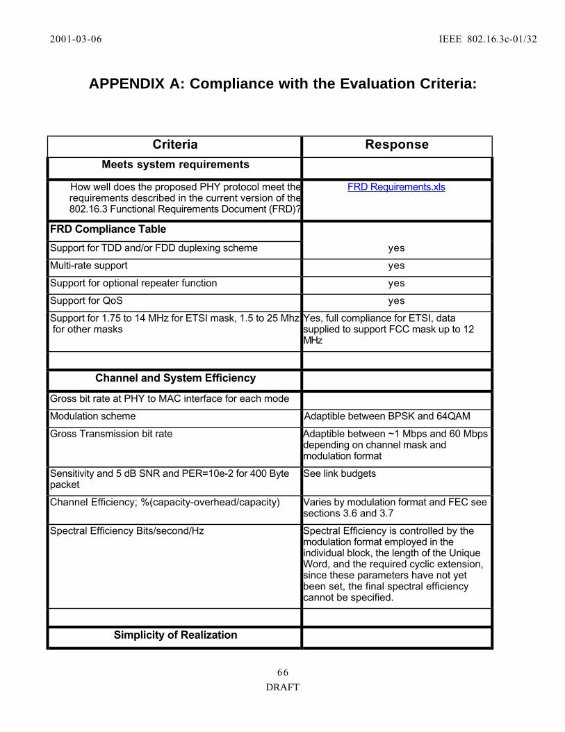
2001-03-06 IEEE 802.16.3c-01/32
DRAFT
66
APPENDIX A: Compliance with the Evaluation Criteria:
Criteria Response
Meets system requirements
How well does the proposed PHY protocol meet therequirements described in the current version of the802.16.3 Functional Requirements Document (FRD)?
FRD Requirements.xls
FRD Compliance Table
Support for TDD and/or FDD duplexing scheme yes
Multi-rate support yes
Support for optional repeater function yes
Support for QoS yes
Support for 1.75 to 14 MHz for ETSI mask, 1.5 to 25 Mhz for other masks
Yes, full compliance for ETSI, datasupplied to support FCC mask up to 12MHz
Channel and System Efficiency
Gross bit rate at PHY to MAC interface for each mode
Modulation scheme Adaptible between BPSK and 64QAM
Gross Transmission bit rate Adaptible between ~1 Mbps and 60 Mbpsdepending on channel mask andmodulation format
Sensitivity and 5 dB SNR and PER=10e-2 for 400 Bytepacket
See link budgets
Channel Efficiency; %(capacity-overhead/capacity) Varies by modulation format and FEC seesections 3.6 and 3.7
Spectral Efficiency Bits/second/Hz Spectral Efficiency is controlled by themodulation format employed in theindividual block, the length of the UniqueWord, and the required cyclic extension,since these parameters have not yetbeen set, the final spectral efficiencycannot be specified.
Simplicity of Realization

2001-03-06 IEEE 802.16.3c-01/32
DRAFT
66
SS cost optimization Minimum cost of RF circuitry due toreduced back off required for upstream
BS cost optimization Minimum cost of RF circuitry due toreduced back off required fordownstream
Installation cost Minimal, single antenna
Spectrum Resource Flexibility
Flexibility in use of the frequency band All channel plans supported
Channel rate flexibility adaptive modulation and coding used toadjust for channel quality
System Robustness to Channel Fading, Interference and Radio Impairments
Small and large scale fading See sections on adaptive modulation,coding and Frequency DomainEqualization
Co-channel and adjacent channel interference Co-channel and adjacent channel leakageare minimized by reduced linearityrequirements of single-carrier modulation
Dgradation due to phase noise, linearity, etc Single carrier modulation systems havelower linearity and phase noiserequirements than OFDM schemes
Compatibility with existing relevant standards and regulations
Relevant FCC standard Fits spectral mask requirements of47CFR21.907

2001-03-06 IEEE 802.16.3c-01/32
DRAFT
66
APPENDIX B: Channel Model For BWA PHY Systems
B.1 Deployment Models
There are three models that describe the deployment of high speed, fixed wireless broadband Internetsystems: the large line-of-sight (LOS) cell, the large non-line-of-sight (NLOS) cell, and clustered NLOS smallcells. Large LOS cells are used in almost one hundred systems in a variety of terrains around the world. Theother two cell models are under development but have not been commercially deployed yet.
The large LOS cell deployment is characterized by tall base station antennas with heights of 200 meters andmore, and Subscriber Station (SS) antennae mounted on the roof or on poles on the roof at heights between 5and 10 meters. In the United States, the licensed frequencies set the cell site radius to 35 miles, however SSsites have been operated out as far as 50 miles. In a number of cases, multiple cells are deployed to service ametropolitan area. The cells typically face inwards towards the market and are situated so that withdirectional SS antennae, there is little cell-to-cell interference.
The NLOS large cell deployments will be an extension of the LOS deployments. The two models share acommon architecture because in many cases the large LOS cell will be adapted to accommodate NLOScustomer sites. LOS and marginal LOS locations will continue to work out to the licensed limit of 35 miles. Because of link budget constraints, NLOS locations will be restricted to distances of about 20 miles. As in the LOS model, inter-cell interference is dependent on Base Station placement and SS antennadirectivity. Systems are designed to minimize the interference.
Small cell site deployments are being considered for regions where the capacity of large cells is not enough toserve the market or where the terrain causes a lot of shadowed areas. Small cell Base Stations use PCS liketowers with antenna heights that range from 15 to 40 meters. The target height of the SS antenna is 2 to 5meters. Small cells are clustered together to provide service over a large area. The cells reuse the licensedfrequencies to increase the overall system capacity. The reuse pattern, antenna patterns, and channelmodels are used to determine the inter-cell interference seen by small cells.
B.2 RF Channel ModelsB.2.1 Large LOS Cells
The RF channel model for large LOS cells is well understood. The attenuation verses distance formulafollows the free space equation of:
PGlos(dB) = 20log(4πd/λ)
Where d is the distance and λ is the wave-length. This model applies to both the upstream and downstreampaths. Seasonal variations are only a few dB. Multipath in LOS is less than 5 mirco seconds at powerlevels of —6 dB from the primary signal in a large percentage of installations using moderately directionalantennae of 220. Less directional antennae see stronger multipath. Rayleigh fading is not a significantfactor in this environment. The fading is flat in channel widths that are 2 MHz and below.
B.2.2 Large NLOS Cells
The RF channel model for large NOS cells is based on the LOS channel model. In both cases the bulk of thetransmission path is characterized by the free space attenuation formula because of the height of the basestation antenna. As a result the free space signal is delivered to a relatively small area near the customerlocation. The signal then under goes additional attenuation that comes not from distance but from the bulkabsorption of few trees and refraction from buildings. This attenuation characterized in unpublished workcan be modeled as a near neighborhood bulk attenuation of between 8 and 30 dB. Because of the influence of

2001-03-06 IEEE 802.16.3c-01/32
DRAFT
66
foliage, seasonal variations in the NLOS signal levels can vary by the amount of near neighborhood bulkattenuation allowed for in the formula. The modified NLOS attenuation formula is given by:
PGnlos(dB) = 20log(4πd/λ) + n
Where n is the near neighborhood bulk attenuation factor. The relative power of multipath signals in NLOScells can be greater because the primary signal may be attenuated more by the bulk attenuation than thereflected signal. However, the size of the multipath delay is similar to that of the LOS case. Thecharacterization of large cell NLOS signals is an area where more field studies are needed. The attenuationmodel presented here applies to both directions of a two-way system. In the downstream, Rayleigh fading isdependant on SS antenna heights. At 4 meters and above the effects of Rayleigh fading are small. Upstreammeasurements are not available for this model but it is safe to assume that Rayleigh fading is the same orsmaller than that seen in the downstream.
B.2.3 NLOS Small Cells
The NLOS small cell channel model is based on the IEEE 802.16.3 paper(http://ieee802.org/16/tg3/contrib/802163c-oo_49r2.pdf). It describes the path for small cell with radiusout to 10 km, Base Station antenna heights up to 40 meters and SS antenna heights between 2 and 8 meters. The mean path loss is given by:
PLsc(dB) = A + 10γlog(d/d0) + S + ∆PLf + ∆PLh
Where A = 20log(4πd0/λ)
γ = (a — bhb + c/hb) {a, b, and c are constants given in the IEEE paper that depend on terrain and hb
is the Base Station antenna height in meters}
d0 = 100 meters
S = lognormal shadow fading (typically set to 10 dB)
∆PLf = Frequency correction = 5.7log (f/2000) f in MHz
∆PLh = SS antenna correction = -10.8log(hcpe/2) hcpe in meters.
At the SS antenna heights considered the Raleigh fading factor, K, is found to be 0, which means there aretypically deep, fast fades from the mean path loss. Multipath is modeled as a delta function at time zero andan exponential drop off with time. In almost all cases, the multipath delays seen in low SS antenna heightsituations are below 12 µsec.
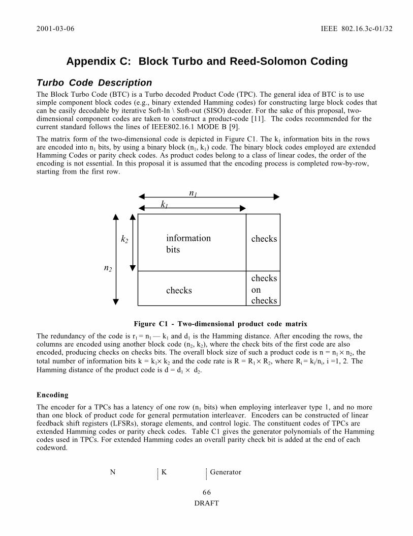
2001-03-06 IEEE 802.16.3c-01/32
DRAFT
66
Appendix C: Block Turbo and Reed-Solomon Coding
Turbo Code DescriptionThe Block Turbo Code (BTC) is a Turbo decoded Product Code (TPC). The general idea of BTC is to usesimple component block codes (e.g., binary extended Hamming codes) for constructing large block codes thatcan be easily decodable by iterative Soft-In \ Soft-out (SISO) decoder. For the sake of this proposal, two-dimensional component codes are taken to construct a product-code [11]. The codes recommended for thecurrent standard follows the lines of IEEE802.16.1 MODE B [9].
The matrix form of the two-dimensional code is depicted in Figure C1. The k1 information bits in the rowsare encoded into n1 bits, by using a binary block (n1, k1) code. The binary block codes employed are extendedHamming Codes or parity check codes. As product codes belong to a class of linear codes, the order of theencoding is not essential. In this proposal it is assumed that the encoding process is completed row-by-row,starting from the first row.
Figure C1 - Two-dimensional product code matrix
The redundancy of the code is r1 = n1 — k1 and d1 is the Hamming distance. After encoding the rows, thecolumns are encoded using another block code (n2, k2), where the check bits of the first code are alsoencoded, producing checks on checks bits. The overall block size of such a product code is n = n1 × n2, thetotal number of information bits k = k1× k2 and the code rate is R = R1 × R2, where Ri = ki/ni, i =1, 2. TheHamming distance of the product code is d = d1 × d2.
Encoding
The encoder for a TPCs has a latency of one row (n1 bits) when employing interleaver type 1, and no morethan one block of product code for general permutation interleaver. Encoders can be constructed of linearfeedback shift registers (LFSRs), storage elements, and control logic. The constituent codes of TPCs areextended Hamming codes or parity check codes. Table C1 gives the generator polynomials of the Hammingcodes used in TPCs. For extended Hamming codes an overall parity check bit is added at the end of eachcodeword.
N K Generator
checksonchecks
checks
checksk2
n2
n1
k1
informationbits

2001-03-06 IEEE 802.16.3c-01/32
DRAFT
66
15 11 x4+ x1 + 1
31 26 x5 + x2 + 1
63 57 x6 + x + 1
Table C1 - Generators Polynomials of Hamming components Codes
In order to encode the product code, each data bit is input both into a row encoder and a column encoder. Note that only one row encoder is necessary for the entire block, since data is input in row order. However,each column of the array must be encoded with separate encoders. Each column encoder is clocked for onlyone bit of the row, so a more efficient method of column encoding is to store the column encoder states in ak1 × (n2-k2) storage memory. A single encoder can then be used for all columns of the array. With each bitinput, the appropriate column encoder state is read from the memory, clocked, and written back to thememory.
The encoding process will be demonstrated with an example. Assume a two-dimensional (8,4) × (8,4)extended Hamming Product code is to be encoded. This block has 16 data bits, and 64 total encoded bits.Figure C2 shows the original 16 data bits denoted by Dyx.
D11 D21 D31 D41
D12 D22 D32 D42
D13 D23 D33 D43
D14 D24 D34 D44
Figure C2 - Original Data for Encoding.
The first four bits of the array are input to the row encoder in the order D11, D21, D31, D41. Each bit is alsoinput to a unique column encoder. Again, a single column encoder may be used, with the state of eachcolumn stored in a memory. After the fourth bit is input, the first row encoder error correction coding(ECC) bits are shifted out.
This process continues for all four rows of data. At this point, 32 bits have been output from the encoder,and the four column encoders are ready to shift out the column ECC bits. This data is shifted out at the endof the row. This continues from the remaining 3 rows of the array. Figure C3 shows the final encoded blockwith the 48 generated ECC bits denoted by Eyx.
D11 D21 D31 D41 E51 E61 E71 E81
D12 D22 D32 D42 E52 E62 E72 E82
D13 D23 D33 D43 E53 E63 E73 E83
D14 D24 D34 D44 E54 E64 E74 E84
E15 E25 E35 E45 E55 E65 E75 E85
E16 E26 E36 E46 E56 E66 E76 E86
E17 E27 E37 E47 E57 E67 E77 E87
E18 E28 E38 E48 E58 E68 E78 E88
Figure C3 - Encoded Block.
Transmission of the block over the channel occurs in a linear fashion, with all bits of the first rowtransmitted left to right followed by the second row, etc. This allows for the construction of a near zerolatency encoder, since the data bits can be sent immediately over the channel, with the ECC bits inserted as

2001-03-06 IEEE 802.16.3c-01/32
DRAFT
66
necessary. For the (8,4)×(8,4) example, the output order for the 64 encoded bits would be D11, D21, D31, D41,E51, E61, E71, E81, D12, D22, E88.
Notation:
• the codes defined for the rows (x-axis) are binary (nx, kx) block codes
• the codes defined for the columns (y-axis) are binary (ny, ky) block codes
• data bits are noted Dy,x and parity bits are noted Ey,x.
Shortened BTCs
To match packet sizes, a product code can be shortened by removing symbols from the array. In the two-dimensional case rows, rows columns or parts thereof can be removed until the appropriate size is reached.Unlike one-dimensional codes (such as Reed-Solomon codes), parity bits are removed as part of shorteningprocess, helping to keep the code rate high.
There are two steps in the process of shortening of product codes. The first step is to remove S2 rows or S1columns from a 2-dimensional code. This is equivalent to shortening the constituent codes that make up theproduct code, i.e, (n1 —S1, k1 —S1) and (n2 —S2, k2- S2). This method enables a coarse granularity onshortening, and at the same time maintaining the highest code rate possible by removing both data and paritysymbols. Further shortening could be obtained by removing individual S bits from the last row of a 2-dimensional code.
Example: To obtain 20 bytes payload based on (32,26)x(32,26) code, set S1=S2=13. The resulted productcode has (19,13)x(19,13) structure which gives 169 payload bits. Then S=9 bits left over which are stuffedwith zeros. Data input to the defined encoder is 160 bits (20 bytes) followed by 9 bits of zeros. The BTCcodeword is transmitted starting with the bit in row 1 column 1 (LSB), then left to right, and then row by
row.
Figure C4 — An Example of Encoded Block.
Block mapping to the signal constellation: The first encoded bit out shall be the LSB, which is the firstbit written into the decoder. When the row is not a multiple of the constellation log-size, then bits fromnext row are used to map bits into symbols.
26 bits 6 bits
6 bits
.
13 bits
13bits

2001-03-06 IEEE 802.16.3c-01/32
DRAFT
66
Shortened last codeword Mode: This mechanism allows by shortening the last codeword a furtherflexibility to more closely match the block size of the BTC with the required message length. The followingsteps describe this mode.
Define a new codeword that has a minimum number of rows that will carry the required number ofinformation bits. The number of columns should be kept unchanged.
If the number of positions for information in the resultant codeword, k , is greater than the number ofinformation bits k1 , then add k — k stuff bits ( 1 ) to the end of the message.
Information bits and stuffed bits k are randomized.
Examples of a Shortened Two-Dimensional BTC
For example, assume a 456-bit block size is required (53+4 bytes for payload), with code rate ofapproximately 0.6. The base code chosen before shortening is the (32,26)×(32,26) code which has a data
size of 676 bits. Shortening all rows by 2 and all columns by 7 results in a (30,24) × (25,19) code, with adata size of 456 bits and the final code is a (750,456) code, with a code rate of 0.608. The following shortened codes are given as examples:
• Product codes based on shortened binary Hamming code:
(2m - S1, 2m-m-1-S1, 4)x(2m - S2 ,2m-m-1-S2, 4 ) where m is the encoder LFSR length
and S, S1 and S2 are configurable shortening parameters.
(19,13)x(19,13) m=5, S1=S2=13, S=9 (20 bytes payload)
(30,24)x(25,19) m=5, S1=2, S2=7 (53+4 bytes payload)
(30,24)x(24,18) m=5, S1=2, S2=8 (53+1 bytes payload)
(39,32)x(39,32) m=6, S1=S2=25 (128bytes payload)
(39,32)x(54,47) m= 6, S1= 25, S2=10 (188 bytes payload)
(63,56)x(63,56) m=6, S1=S2=1 (392 bytes payload).
• Product codes based on binary parity-check codes:
(2k+1, 2k) X (2k+1, 2k) where k is configurable. (max k=32, min k =TBD).
Iterative Decoding
Each block code in a product code is decoded independently. First, all the horizontal blocks are decodedthen all the vertical received blocks are decoded (or vice versa). The decoding procedure is generallyiterated several times to maximize the decoder performance. To achieve optimal performance, the blockby block decoding must be done utilizing soft information. This soft decision decoder must also output asoft decision metric corresponding to the likelihood that the decoder output bit is correct. This isrequired so that the next decoding will have soft input information as well. In this way, each decodingiteration builds on the previous decoding performance.
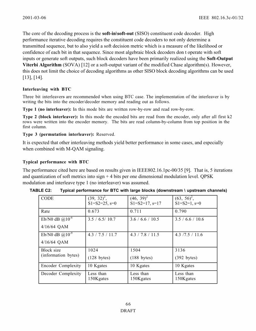
2001-03-06 IEEE 802.16.3c-01/32
DRAFT
66
The core of the decoding process is the soft-in\soft-out (SISO) constituent code decoder. Highperformance iterative decoding requires the constituent code decoders to not only determine atransmitted sequence, but to also yield a soft decision metric which is a measure of the likelihood orconfidence of each bit in that sequence. Since most algebraic block decoders don t operate with softinputs or generate soft outputs, such block decoders have been primarily realized using the Soft-OutputViterbi Algorithm (SOVA) [12] or a soft-output variant of the modified Chase algorithm(s). However,this does not limit the choice of decoding algorithms as other SISO block decoding algorithms can be used[13], [14].
Interleaving with BTC
Three bit interleavers are recommended when using BTC case. The implementation of the interleaver is bywriting the bits into the encoder/decoder memory and reading out as follows.
Type 1 (no interleaver): In this mode bits are written row-by-row and read row-by-row.
Type 2 (block interleaver): In this mode the encoded bits are read from the encoder, only after all first k2rows were written into the encoder memory. The bits are read column-by-column from top position in thefirst column.
Type 3 (permutation interleaver): Reserved.
It is expected that other interleaving methods yield better performance in some cases, and especiallywhen combined with M-QAM signaling.
Typical performance with BTC
The performance cited here are based on results given in IEEE802.16.1pc-00/35 [9]. That is, 5 iterationsand quantization of soft metrics into sign + 4 bits per one dimensional modulation level. QPSKmodulation and interleave type 1 (no interleaver) was assumed.
TABLE C2: Typical performance for BTC with large blocks (downstream \ upstream channels)
CODE (39, 32)2, S1=S2=25, s=0
(46, 39)2 S1=S2=17, s=17
(63, 56)2, S1=S2=1, s=0
Rate 0.673 0.711 0.790
Eb/N0 dB @10-6
4/16/64 QAM
3.5 / 6.5/ 10.7 3.6 / 6.6 / 10.5 3.5 / 6.6 / 10.6
Eb/N0 dB @10-9
4/16/64 QAM
4.3 / 7.5 / 11.7 4.3 / 7.8 / 11.5 4.3 /7.5 / 11.6
Block size(information bytes)
1024
(128 bytes)
1504
(188 bytes)
3136
(392 bytes)
Encoder Complexity 10 Kgates 10 Kgates 10 Kgates
Decoder Complexity Less than150Kgates
Less than150Kgates
Less than150Kgates

2001-03-06 IEEE 802.16.3c-01/32
DRAFT
66
TABLE C3: Typical performance for BTC with small blocks (upstream channel)
CODE (16, 11)2, S1=S2=0, s=1
(30, 24)x(25, 19) S1=2, S2=7, s=0
Rate 0.469 0.608
Eb/N0 dB @10-6
4/16/64 QAM
4.0 / 6.8/ 9.8 3.4 / 6.3 / 10
Eb/N0 dB @10-9
4/16/64 QAM
5.8 / 8.8 / 11.8 4.7 / 7.5 / 11.5
Block size(information bytes)
120
(15 bytes)
456
(57 bytes)
Encoder Complexity 10 Kgates 10 Kgates
Decoder Complexity Less than150Kgates
Less than150Kgates
Combining Turbo Product Codes With M-QAM
The downstream channel supports both continuous and burst mode operation and the proposed FECincorporates turbo product codes, for each of these applications. In order to provide the desiredflexibility and the required QoS, TPCs are used in conjunction with adaptive modulation scheme wheredifferent modulation formats and TPC s are specified on a frame-by-frame basis. Mapping of theencoded bits into the desired modulation is arranged in Gray code format, as shown in Figure C5.
Fig.C5. Signal Mapping for 16QAM
- 1- 3
3
1
- 3
- 1
1
q
i
1000 1001 1011 1010
1100 1101 1111 1110
0100 0101 0111 0110
0000 0001 0011 0010
3
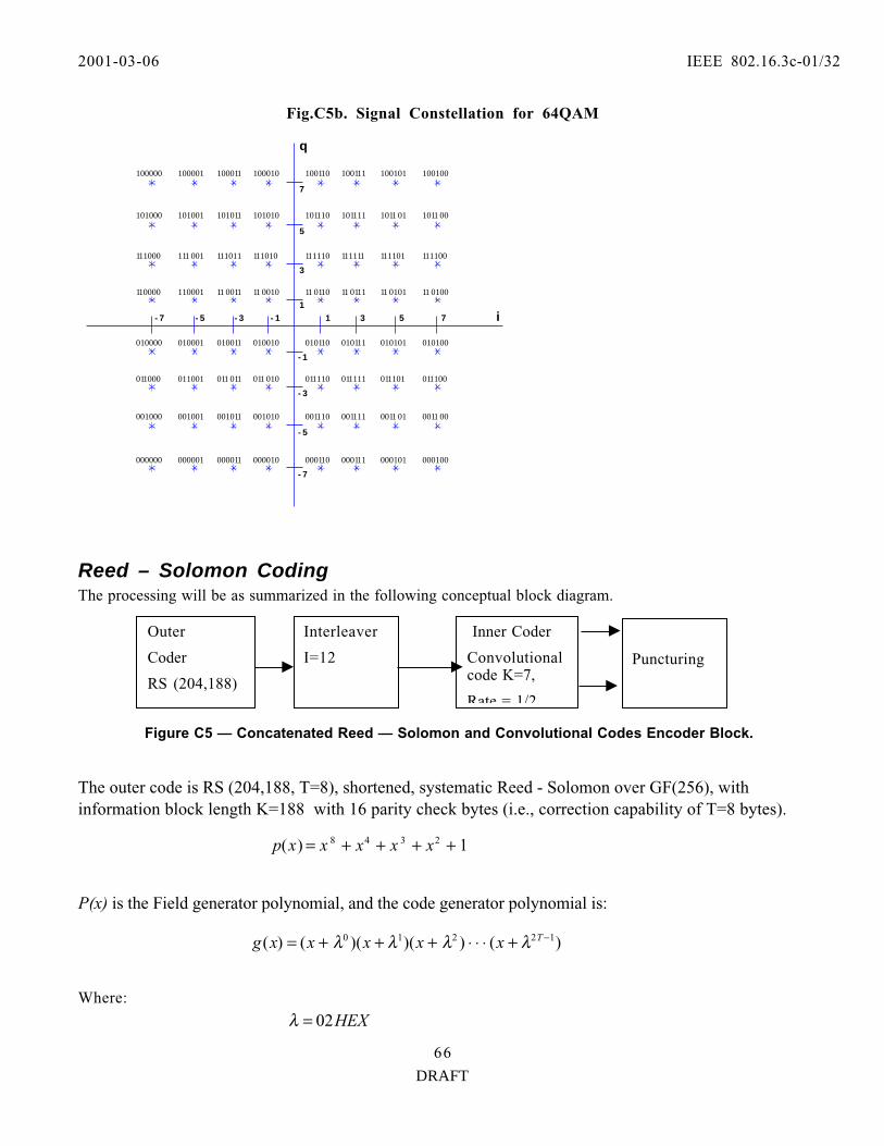
2001-03-06 IEEE 802.16.3c-01/32
DRAFT
66
Fig.C5b. Signal Constellation for 64QAM
Reed – Solomon CodingThe processing will be as summarized in the following conceptual block diagram.
Figure C5 — Concatenated Reed — Solomon and Convolutional Codes Encoder Block.
The outer code is RS (204,188, T=8), shortened, systematic Reed - Solomon over GF(256), withinformation block length K=188 with 16 parity check bytes (i.e., correction capability of T=8 bytes).
P(x) is the Field generator polynomial, and the code generator polynomial is:
Where:
- 1- 3
3
1
- 3
- 1
1
q
i
110000 110001 11 0010 11 0110
5
- 7
- 7 3 7
11 0111 11 0101
7
- 5
5- 5
11 0011 11 0100
111000 111 001 111010 111110 111111 111101111011 111100
101000 101001 101010 101110 101111 1011 01101011 1011 00
100000 100001 100010 100110 100111 100101100011 100100
010000 010001 010010 010110 010111 010101010011 010100
011000 011001 011 010 011110 011111 011101011 011 011100
001000 001001 001010 001110 001111 0011 01001011 0011 00
000000 000001 000010 000110 000111 000101000011 000100
Outer
Coder
RS (204,188)
Interleaver
I=12
Inner Coder
Convolutionalcode K=7,
Rate = 1/2
Puncturing
1)( 2348 ++++= xxxxxp
)())()(()( 12210 −+⋅⋅⋅+++= Txxxxxg λλλλ
HEX02=λ

2001-03-06 IEEE 802.16.3c-01/32
DRAFT
66
λ is a primitive root of p(x).
The shortened RS is obtained from RS (255,239,T=8) code by adding 51 bytes, all set to zero, before theinformation bytes at the input of a RS (255,239) encoder. After encoding these nulls are discarded.The convolutioal symbol interleaver is depth I=12 based on Forney approach [8].
Inner Convolutional coding: based on rate 1/2 Convolutional code with constraint length K=7,corresponding to 64 trellis states described by gererators G1=171 Octal and G2=133 Octal.
Figure C6 — Convolutional Encoder Diagram.
The inner Convolutional code has puncturing configuration defined in the following table. In this notations,(x, y) denotes a bit pairs at the output of the Convolutional encoder.
"1" in a puncture pattern means transmitted bit while "0" denotes non-transmitted bit. These bit pairs willbe used for Gray coded (I, Q) mapping.
TABLE C4: The inner Convolutional code with Puncturing Configuration
Code ratesOriginalCode
1/2 2/3 3/4 5/6 7/8
1-bitdelay
1-bitdelay
1-bitdelay
1-bitdelay
1-bitdelay
1-bitdelay
Modulo-2 adder (133 Octal)
Modulo-2 adder (171 Octal)
Y output
X output

2001-03-06 IEEE 802.16.3c-01/32
DRAFT
66
K G1 G2 P dfree P dfree P dfree P dfree P dfree
7 171
133
X: 1
Y: 1
I=X1
Q=Y1
10
X: 10
Y: 11
I=X1Y2Y3
Q=Y1X3Y4
6
X:101
Y:110
I= X1Y2
Q=Y1X3
5
X˚:10101
Y˚:11010
I= X1Y2Y4
Q=Y1X3X5
4
X:1000101
Y:1111010
I=X1Y2Y4Y6
Q=Y1Y3X5X7
3
Error Performance requirements with RS (204,188) + inner Convolutional coding (IF loop results, based on[9 Table 5] for AWGN @ BER =10-8).
TABLE C5: The inner Convolutional code with Puncturing Configuration
Modulation Inner code rate Spectralefficiency
Aggregatecode rate
Eb/N0 dB *
QPSK 1/2 0.92 0.46 4
2/3 1.23 0.61 4.5
3/4 1.38 0.69 5.0
5/6 1.53 0.77 5.5
7/8 1.61 0.81 5.9
3/4 2.76 0.69 8.516QAM
7/8 3.22 0.81 10.2
* Notes: the figures cited here includes: 0.8 dB implementation loss for QPSK, and1.5, 2.1 dB for the _, 7/8, 16QAM, respectively.