Embed Size (px)
Citation preview
DAQCard™, DAQPad™, National Instruments™, and ni.com™ are trademarks of National Instruments Corporation. Product and company names mentioned herein are trademarks or trade names of their respective companies.
371217A-01 © Copyright 2000 National Instruments Corp. All rights reserved. April 2000
USER GUIDE
SC-2075 SIGNAL CONDITIONING ACCESSORYThe SC-2075 is a desktop signal conditioner that you can connect directly to National Instruments E Series or 1200 Series devices. The SC-2075 has the following features:
• Binding posts
– Three for ±15 V outputs
– Two for 0 to 5 V outputs
– Two for measuring analog signals or DC voltages
• BNC connectors
– Two for analog inputs
– Two for analog outputs
– One for triggering
• Spring terminals
– Eleven for analog inputs
– Seven for analog controls
– Seven for counter controls
– Two for TTL-level power and ground signals
– Eight for digital input/output (DIO) signals

SC-2075 Signal Conditioning Accessory 2 www.ni.com
What You Need to Get StartedTo set up and use your SC-2075, you need the following items:
SC-2075 signal conditioner
SC-2075 Signal Conditioning Accessory User Guide
68-pin E Series device and 68-pin cableor 50-pin 1200 Series device and 50-pin ribbon cable
BNC cables
Banana plug cables
Wire no larger than 24 AWG
Wire strippers
Safety glasses
ConventionsThe following conventions are used in this guide:
This icon denotes a note, which alerts you to important information.
This icon denotes a caution, which advises you of precautions to take to avoid injury, data loss, or a system crash.
This icon, which is found on the SC-2075 signal conditioning accessory, denotes a hot surface hazard. It advises you to take precautions to avoid burns.
bold Bold text denotes E Series signal names.
italic Italic text denotes emphasis, a cross reference, a label name, or a 1200 Series signal name
© National Instruments Corporation 3 SC-2075 Signal Conditioning Accessory
Safety Information
Cautions Do not operate the device in an explosive atmosphere or where there may be flammable gases or fumes.
Do not operate damaged equipment. The safety protection features built into this device can become impaired if the device becomes damaged in any way. If the device is damaged, turn the device off and do not use until service-trained personnel can check its safety. If necessary, return the device to National Instruments for service and repair to ensure that its safety is not compromised.
Do not operate this equipment in a manner that contradicts the information specified in this document.
Do not substitute parts or modify equipment. Because of the danger of introducing additional hazards, do not install unauthorized parts or modify the device. Return the device to National Instruments for service and repair to ensure that its safety features are not compromised.
Connections, including power signals to ground and vice versa, that exceed any of the maximum signal ratings on the device can create a shock or fire hazard or can damage any or all of the devices connected to the SC-2075 and the host computer. National Instruments is not liable for any damages or injuries resulting from incorrect signal connections.
Clean the device by brushing off light dust with a soft, nonmetallic brush. Remove other contaminants with deionized water and a stiff nonmetallic brush. The unit must be completely dry and free from contaminants before returning to service.
The SC-2075 can have sharp edges. To avoid injury, use caution when handling the device
When your SC-2075 is powered on, always wear safety glasses when working with prototype circuits you design.The SC-2075 can have sharp edges.
SC-2075 Signal Conditioning Accessory 4 www.ni.com
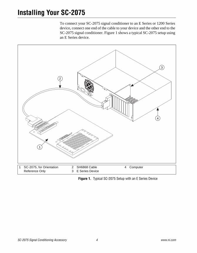
Installing Your SC-2075To connect your SC-2075 signal conditioner to an E Series or 1200 Series device, connect one end of the cable to your device and the other end to the SC-2075 signal conditioner. Figure 1 shows a typical SC-2075 setup using an E Series device.
Figure 1. Typical SC-2075 Setup with an E Series Device
1 SC-2075, for Orientation Reference Only
2 SH6868 Cable3 E Series Device
4 Computer
1
4
3
2

© National Instruments Corporation 5 SC-2075 Signal Conditioning Accessory
Figure 2 shows the location of all SC-2075 connections.
Figure 2. SC-2075 Connection Location Diagram
The three power indicator LEDs should be lit when switch SW1 is in the External or Internal position. When SW1 is in the External position, a +5 VDC external power source supplies power to the DC Power Jack. When SW1 is in the Internal position, the E Series or 1200 Series device supplies the power. When SW1 is in the Off position, all power is off and all LEDs should be off. Table 1 shows the power source, switch position, and LED status of possible SC-2075 power configurations. If any of the LEDs are not lit in a configuration in which they should be lit, verify that
1 E Series Connector2 1200 Series Connector3 DC Power Jack4 +5 V Power Select Switch SW15 Fuses6 Serial Number7 0–5 V Potentiometer8 Analog Input Spring Terminals
9 Legend10 Power LED Status Indicators11 Analog Output BNCs12 Analog Input BNCs13 Trigger BNC14 Analog Input Banana Plugs15 DC Power Output Banana Plugs
16 Product Name17 Assembly Number18 Prototyping Breadboard Area19 Control Spring Terminals29 Counter Spring Terminals21 DIO Spring Terminals22 DIO LED Status Indicators
1
2
22 21 20
8
19
976
3
4
11 12 13
14
15
16
17
18
10
5
SC-2075 Signal Conditioning Accessory 6 www.ni.com
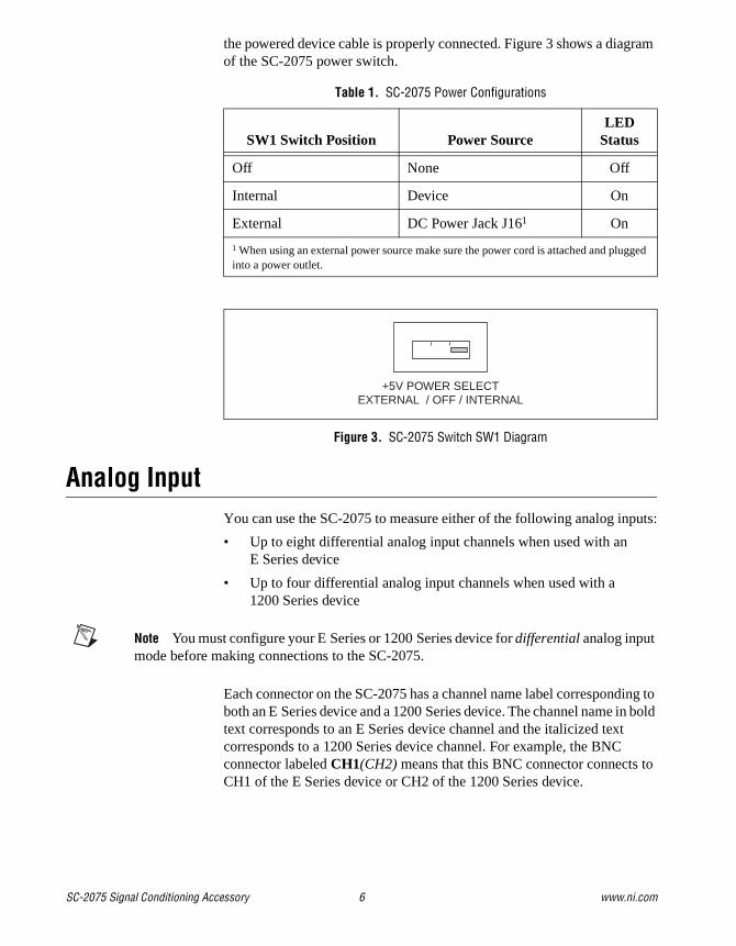
the powered device cable is properly connected. Figure 3 shows a diagram of the SC-2075 power switch.
Figure 3. SC-2075 Switch SW1 Diagram
Analog InputYou can use the SC-2075 to measure either of the following analog inputs:
• Up to eight differential analog input channels when used with an E Series device
• Up to four differential analog input channels when used with a 1200 Series device
Note You must configure your E Series or 1200 Series device for differential analog input mode before making connections to the SC-2075.
Each connector on the SC-2075 has a channel name label corresponding to both an E Series device and a 1200 Series device. The channel name in bold text corresponds to an E Series device channel and the italicized text corresponds to a 1200 Series device channel. For example, the BNC connector labeled CH1(CH2) means that this BNC connector connects to CH1 of the E Series device or CH2 of the 1200 Series device.
Table 1. SC-2075 Power Configurations
SW1 Switch Position Power SourceLED
Status
Off None Off
Internal Device On
External DC Power Jack J161 On
1 When using an external power source make sure the power cord is attached and plugged into a power outlet.
+5V POWER SELECTEXTERNAL / OFF / INTERNAL
© National Instruments Corporation 7 SC-2075 Signal Conditioning Accessory
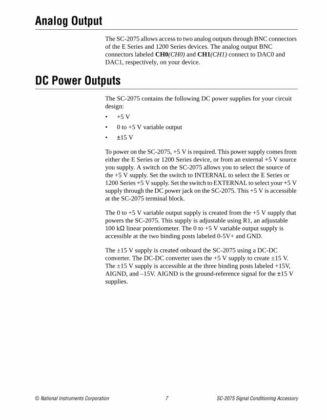
Analog OutputThe SC-2075 allows access to two analog outputs through BNC connectors of the E Series and 1200 Series devices. The analog output BNC connectors labeled CH0(CH0) and CH1(CH1) connect to DAC0 and DAC1, respectively, on your device.
DC Power OutputsThe SC-2075 contains the following DC power supplies for your circuit design:
• +5 V
• 0 to +5 V variable output
• ±15 V
To power on the SC-2075, +5 V is required. This power supply comes from either the E Series or 1200 Series device, or from an external +5 V source you supply. A switch on the SC-2075 allows you to select the source of the +5 V supply. Set the switch to INTERNAL to select the E Series or 1200 Series +5 V supply. Set the switch to EXTERNAL to select your +5 V supply through the DC power jack on the SC-2075. This +5 V is accessible at the SC-2075 terminal block.
The 0 to +5 V variable output supply is created from the +5 V supply that powers the SC-2075. This supply is adjustable using R1, an adjustable 100 kΩ linear potentiometer. The 0 to +5 V variable output supply is accessible at the two binding posts labeled 0-5V+ and GND.
The ±15 V supply is created onboard the SC-2075 using a DC-DC converter. The DC-DC converter uses the +5 V supply to create ±15 V. The ±15 V supply is accessible at the three binding posts labeled +15V, AIGND, and –15V. AIGND is the ground-reference signal for the ±15 V supplies.

SC-2075 Signal Conditioning Accessory 8 www.ni.com
Table 2 details the maximum output power available from the +5 V and ±15 V supplies when used with the E Series or 1200 Series devices.
A power calculation is given in the following example.
Given that you are using a PCI E Series device and the SC-2075, and your prototype circuit requires +5 V at 100 mA and ±15 V at 20 mA. Will the PCI E Series device supply the needed power?
1. Determine your power requirements:
• +5 V × 100 mA = 0.5 W (+5 V power required)
• +15 V × 20 mA = 0.3 W (+15 V power required)
• –15 V × 20mA = 0.3 W (–15 V power required)
2. Determine if this setup will work:
a. 4.2 W – 0.5 W = 3.7 W (+5 V power remaining for DC-DC converter)
b. 3.7 W × 72% (efficiency of DC-DC) = 2.7 W (±15 V power available)
c. 2.7 W / 2 supplies = 1.35 W (+15 V or –15 V power available)
Since 1.35 W > 0.3 W is true, the PCI E Series device will supply the needed power.
The SC-2075 contains two, 1.1 A, self-resetting fuses—one on the DC power jack and one on the +5 V output of the power selection switch. If either fuse trips, it resets after the SC-2075 is powered off for 15 seconds. To power off the SC-2075, set the power switch, SW1, on the SC-2075 to the OFF position for 15 seconds.
Table 2. Maximum Output Power Available
Device Type Power Source +5 VDC1 +15 VDC2 –15 VDC2
E Series Device AT/PCI 4.2 W (835 mA)
1.5 W (100 mA)
1.5 W (100 mA)
DAQCard/DAQPad 0.43 W (85 mA)
0.15 W (10 mA)
0.15 W (10 mA)
1200 Series Device AT/PCI/DAQPad 1.2 W (235 mA)
0.59 W (28 mA)
0.59 W (28 mA)
DAQCard 1.7 W (335 mA)
0.84 W (40 mA)
0.84 W (40 mA)
1 +5 VDC specs in table assume no load on the ±15 VDC supply.2 ±15 VDC specs in table assume no load on +5 VDC supply

© National Instruments Corporation 9 SC-2075 Signal Conditioning Accessory
Digital I/OThe SC-2075 contains spring terminal access to the DIO channels of the E Series or 1200 Series device. Eight LEDs correlating to the eight DIO lines indicate the state of each digital channel. If the LED is lit, the channel is either pulled high (high > 2.6 V) or driven high. If the LED is off, the channel is either pulled low (low < 0.4 V) or driven low.
A ground is available at the spring terminal labeled GND and is the reference for the DIO lines.
Timing and Control I/OThe SC-2075 contains spring terminal access to the timing I/O signals of an E Series or 1200 Series device.
Each connector on the SC-2075 has a channel name label corresponding to both an E Series device and a 1200 Series device. The channel name in bold plain text corresponds to an E Series device channel and the italicized text corresponds to a 1200 Series device channel. For example, the spring terminal connector labeled CONVERT* (EXTCONV*) indicates that this terminal connects to PFI2/CONVERT* of the E Series device or EXTCONV* of the 1200 Series device.

SC-2075 Signal Conditioning Accessory 10 www.ni.com
SpecificationsThis section lists the SC-2075 specifications and are typical at 25 °C unless otherwise specified.
Analog InputNumber of channels
E Series............................................8 differential
1200 Series ......................................4 differential
Connector types and signals
SC-2075 Connector/Signal NameE Series
Signal Name1200 Series
Signal Name
Binding Posts / CH0+(CH0+) ACH0 ACH0
Binding Posts / CH0–(CH0–) ACH8 ACH1
BNC / CH1(CH2) ACH1/9 ACH2/3
BNC / CH2(CH4) ACH2/10 ACH4/5
BNC / TRIG1 (EXTTRIG) PFI0/TRIG1 TRIG1/EXTTRIG
Spring Terminals / CH3+(CH6+) ACH3 ACH6
Spring Terminals / CH3–(CH6–) ACH11 ACH7
Spring Terminals / CH4+(N/A) ACH4 N/A
Spring Terminals / CH4–(N/A) ACH12 N/A
Spring Terminals / CH5+(N/A) ACH5 N/A
Spring Terminals / CH5–(N/A) ACH13 N/A
Spring Terminals / CH6+(N/A) ACH6 N/A
Spring Terminals / CH6–(N/A) ACH14 N/A
Spring Terminals / CH7+(N/A) ACH7 N/A
Spring Terminals / CH7–(N/A) ACH15 N/A
© National Instruments Corporation 11 SC-2075 Signal Conditioning Accessory
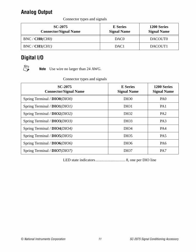
Analog OutputConnector types and signals
Digital I/O
Note Use wire no larger than 24 AWG.
Connector types and signals
LED state indicators............................... 8, one per DIO line
SC-2075Connector/Signal Name
E Series Signal Name
1200 Series Signal Name
BNC / CH0(CH0) DAC0 DACOUT0
BNC / CH1(CH1) DAC1 DACOUT1
SC-2075Connector/Signal Name
E Series Signal Name
1200 Series Signal Name
Spring Terminal / DIO0(DIO0) DIO0 PA0
Spring Terminal / DIO1(DIO1) DIO1 PA1
Spring Terminal / DIO2(DIO2) DIO2 PA2
Spring Terminal / DIO3(DIO3) DIO3 PA3
Spring Terminal / DIO4(DIO4) DIO4 PA4
Spring Terminal / DIO5(DIO5) DIO5 PA5
Spring Terminal / DIO6(DIO6) DIO6 PA6
Spring Terminal / DIO7(DIO7) DIO7 PA7
SC-2075 Signal Conditioning Accessory 12 www.ni.com
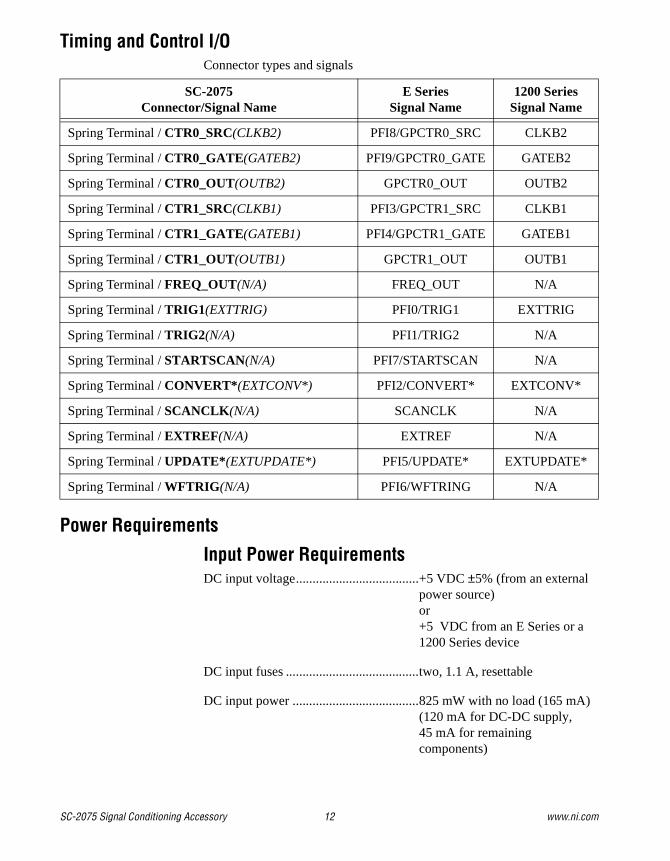
Timing and Control I/OConnector types and signals
Power Requirements
Input Power RequirementsDC input voltage.....................................+5 VDC ±5% (from an external
power source)or+5 VDC from an E Series or a 1200 Series device
DC input fuses ........................................two, 1.1 A, resettable
DC input power ......................................825 mW with no load (165 mA)(120 mA for DC-DC supply, 45 mA for remaining components)
SC-2075Connector/Signal Name
E Series Signal Name
1200 Series Signal Name
Spring Terminal / CTR0_SRC(CLKB2) PFI8/GPCTR0_SRC CLKB2
Spring Terminal / CTR0_GATE(GATEB2) PFI9/GPCTR0_GATE GATEB2
Spring Terminal / CTR0_OUT(OUTB2) GPCTR0_OUT OUTB2
Spring Terminal / CTR1_SRC(CLKB1) PFI3/GPCTR1_SRC CLKB1
Spring Terminal / CTR1_GATE(GATEB1) PFI4/GPCTR1_GATE GATEB1
Spring Terminal / CTR1_OUT(OUTB1) GPCTR1_OUT OUTB1
Spring Terminal / FREQ_OUT(N/A) FREQ_OUT N/A
Spring Terminal / TRIG1 (EXTTRIG) PFI0/TRIG1 EXTTRIG
Spring Terminal / TRIG2 (N/A) PFI1/TRIG2 N/A
Spring Terminal / STARTSCAN(N/A) PFI7/STARTSCAN N/A
Spring Terminal / CONVERT* (EXTCONV*) PFI2/CONVERT* EXTCONV*
Spring Terminal / SCANCLK (N/A) SCANCLK N/A
Spring Terminal / EXTREF (N/A) EXTREF N/A
Spring Terminal / UPDATE* (EXTUPDATE*) PFI5/UPDATE* EXTUPDATE*
Spring Terminal / WFTRIG (N/A) PFI6/WFTRING N/A
© National Instruments Corporation 13 SC-2075 Signal Conditioning Accessory
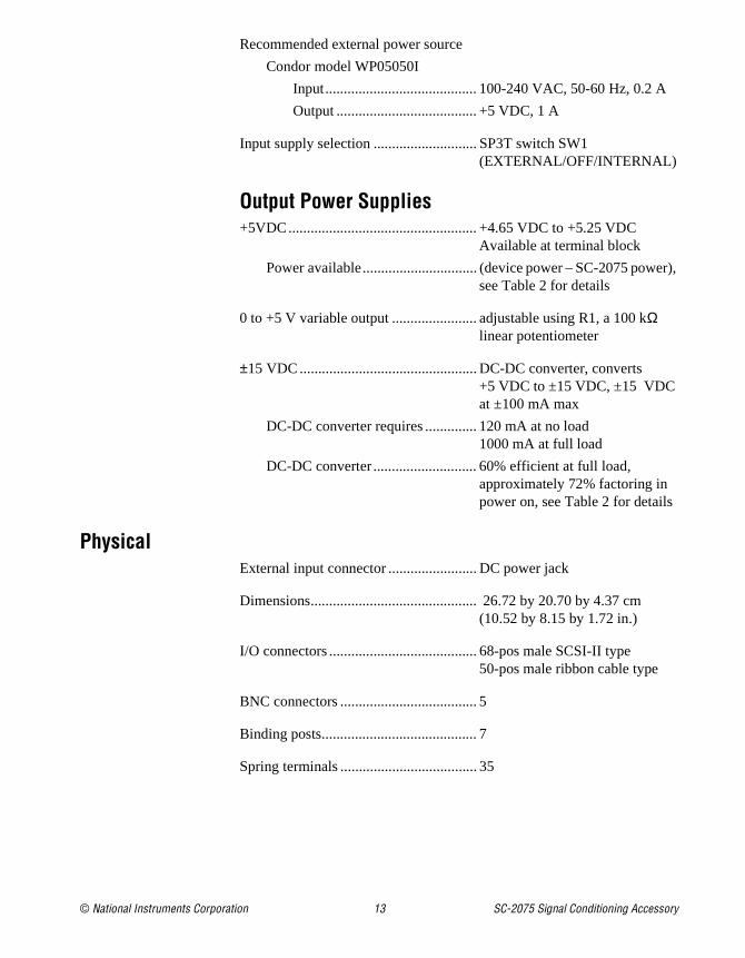
Recommended external power source
Condor model WP05050I
Input......................................... 100-240 VAC, 50-60 Hz, 0.2 A
Output ...................................... +5 VDC, 1 A
Input supply selection ............................ SP3T switch SW1 (EXTERNAL/OFF/INTERNAL)
Output Power Supplies+5VDC................................................... +4.65 VDC to +5.25 VDC
Available at terminal block
Power available............................... (device power – SC-2075 power), see Table 2 for details
0 to +5 V variable output ....................... adjustable using R1, a 100 kΩ linear potentiometer
±15 VDC ................................................ DC-DC converter, converts +5 VDC to ±15 VDC, ±15 VDC at ±100 mA max
DC-DC converter requires .............. 120 mA at no load1000 mA at full load
DC-DC converter ............................ 60% efficient at full load, approximately 72% factoring in power on, see Table 2 for details
PhysicalExternal input connector ........................ DC power jack
Dimensions............................................. 26.72 by 20.70 by 4.37 cm(10.52 by 8.15 by 1.72 in.)
I/O connectors ........................................ 68-pos male SCSI-II type50-pos male ribbon cable type
BNC connectors ..................................... 5
Binding posts.......................................... 7
Spring terminals ..................................... 35
SC-2075 Signal Conditioning Accessory 14 www.ni.com
EnvironmentOperating temperature ............................0 to 40 °C
SafetyDesigned in accordance with IEC 61010-1, UL 3111-1, and CAN/CSA C22.2 No. 1010.1 for electrical measuring and test equipment
Approved at altitudes up to 2000 m
Installation Category II
Pollution Degree 2

© National Instruments Corporation 15 SC-2075 Signal Conditioning Accessory
Technical Support Resources
NI Web SupportTo provide you with immediate answers and solutions 24 hours a day, 365 days a year, National Instruments maintains extensive online technical support resources. They are available to you at no cost, are updated daily, and can be found in the Technical Support section of our Web site at www.ni.com/support
Worldwide SupportNational Instruments has offices located around the globe. Many branch offices maintain a Web site to provide information on local services. You can access these Web sites from www.ni.com/worldwide
For telephone support in the United States, dial 512 795 8248. For telephone support outside the United States, contact your local branch office:
Australia 03 9879 5166, Austria 0662 45 79 90 0, Belgium 02 757 00 20, Brazil 011 284 5011, Canada (Calgary) 403 274 9391, Canada (Ontario) 905 785 0085, Canada (Québec) 514 694 8521, China 0755 3904939, Denmark 45 76 26 00, Finland 09 725 725 11, France 01 48 14 24 24, Germany 089 741 31 30, Greece 30 1 42 96 427, Hong Kong 2645 3186, India 91805275406, Israel 03 6120092, Italy 02 413091, Japan 03 5472 2970, Korea 02 596 7456, Mexico (D.F.) 5 280 7625, Mexico (Monterrey) 8 357 7695, Netherlands 0348 433466, New Zealand 09 914 0488, Norway 32 27 73 00, Poland 0 22 528 94 06, Portugal 351 1 726 9011, Singapore 2265886, Spain 91 640 0085, Sweden 08 587 895 00, Switzerland 056 200 51 51, Taiwan 02 2528 7227, United Kingdom 01635 523545