Embed Size (px)
Citation preview
SBS-S SERIES LOAD BANK USER MANUAL
Rev 1.1 9-24-2013
SBS-S SERIES DC LOAD BANK USER MANUAL
Models Covered
SBS-4830S
SBS-1110S SBS-1230S
SBS-2206S SBS-2415S
99 Washington Street Melrose, MA 02176 Phone 781-665-1400Toll Free 1-800-517-8431
Visit us at www.TestEquipmentDepot.com
SBS-S SERIES LOAD BANK USER MANUAL
Rev 1.1 9-24-2013
Contents
OPERATING INSTRUCTIONS 1. Environments Requirement2. Main Tester Description3. Main Tester Connection4. Start Up and Input Operation5. Parameter setting6. Starting Discharge Test7. Stopping Discharge Test8. Test result9. Calibration interface
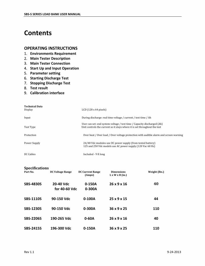
Technical Data Display LCD (128 x 64 pixels)
Input During discharge: real time voltage / current / test time / Ah discharged
User can set: end system voltage / test time / Capacity discharged (Ah) Test Type Unit controls the current so it stays where it is set throughout the test
Protection Over heat / Over load / Over voltage protection with audible alarm and screen warning
Power Supply 24/48 Vdc modules use DC power supply (from tested battery) 125 and 250 Vdc models use AC power supply (120 Vac 60 Hz)
DC Cables Included - 9 ft long
Specifications Part No. DC Voltage Range DC Current Range
(Amps) Dimensions
L x W x H (in.) Weight (lbs.)
SBS-4830S 20-40 Vdc 0-150A 26 x 9 x 16 40
for 40-60 Vdc 0-300A
SBS-1110S 90-150 Vdc 0-100A 25 x 9 x 15 44
SBS-1230S 90-150 Vdc 0-300A 36 x 9 x 25 110
SBS-2206S 190-265 Vdc 0-60A 26 x 9 x 16 40
SBS-2415S 196-300 Vdc 0-150A 36 x 9 x 25 110
SBS-S SERIES LOAD BANK USER MANUAL
Rev 1.1 9-24-2013
OPERATING INSTRUCTIONS 1. Environments RequirementShould be NO CORROSIVE,NO EXPLOSIVE,NO ELECTRICAL BREAKDOWN AIR OR CONDUCTIVE DUST.
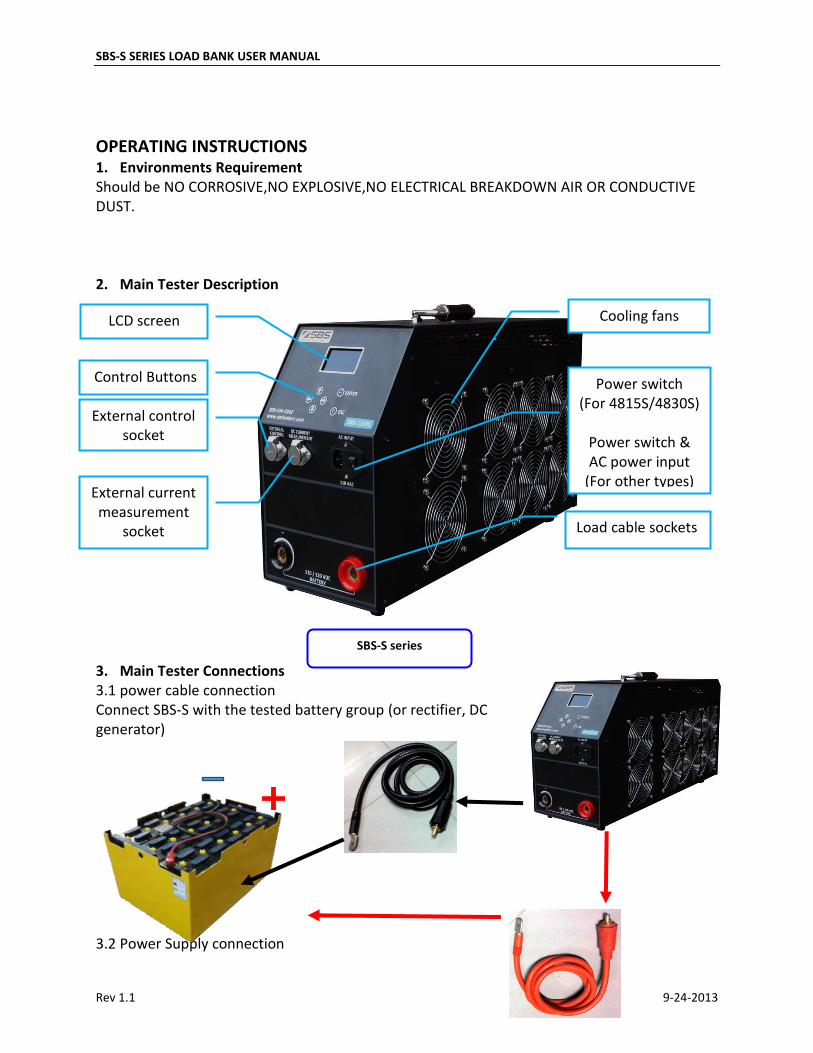
2. Main Tester Description
3. Main Tester Connections3.1 power cable connection Connect SBS-S with the tested battery group (or rectifier, DC generator)
3.2 Power Supply connection
Cooling fans LCD screen
Control Buttons
External control socket
External current measurement
socket
Power switch (For 4815S/4830S)
Power switch & AC power input
(For other types)
Load cable sockets
SBS-S series
SBS-S SERIES LOAD BANK USER MANUAL
Rev 1.1 9-24-2013
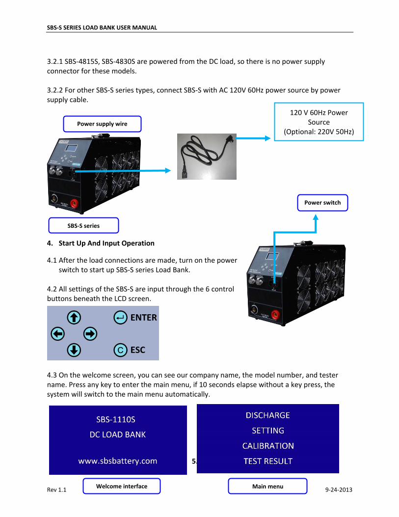
3.2.1 SBS-4815S, SBS-4830S are powered from the DC load, so there is no power supply connector for these models.
3.2.2 For other SBS-S series types, connect SBS-S with AC 120V 60Hz power source by power supply cable.
4. Start Up And Input Operation
4.1 After the load connections are made, turn on the power switch to start up SBS-S series Load Bank.
4.2 All settings of the SBS-S are input through the 6 control buttons beneath the LCD screen.
4.3 On the welcome screen, you can see our company name, the model number, and tester name. Press any key to enter the main menu, if 10 seconds elapse without a key press, the system will switch to the main menu automatically.
5. Parameter setting
Power switch
Main menu
120 V 60Hz Power Source
(Optional: 220V 50Hz)
SBS-S series
Power supply wire
Welcome interface
SBS-S SERIES LOAD BANK USER MANUAL
Rev 1.1 9-24-2013
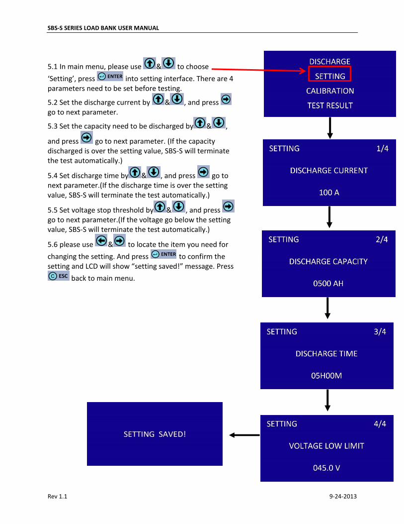
5.1 In main menu, please use & to choose
‘Setting’, press into setting interface. There are 4 parameters need to be set before testing.
5.2 Set the discharge current by & , and press go to next parameter.
5.3 Set the capacity need to be discharged by & ,
and press go to next parameter. (If the capacity discharged is over the setting value, SBS-S will terminate the test automatically.)
5.4 Set discharge time by & , and press go to next parameter.(If the discharge time is over the setting value, SBS-S will terminate the test automatically.)
5.5 Set voltage stop threshold by & , and press go to next parameter.(If the voltage go below the setting value, SBS-S will terminate the test automatically.)
5.6 please use & to locate the item you need for
changing the setting. And press to confirm the setting and LCD will show “setting saved!” message. Press
back to main menu.
SBS-S SERIES LOAD BANK USER MANUAL
Rev 1.1 9-24-2013
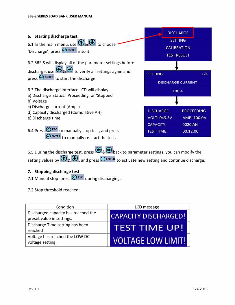
6. Starting discharge test
6.1 In the main menu, use & to choose
‘Discharge’, press into it.
6.2 SBS-S will display all of the parameter settings before
discharge, use & to verify all settings again and
press to start the discharge.
6.3 The discharge interface LCD will display: a) Discharge status: ‘Proceeding’ or ‘Stopped’b) Voltagec) Discharge current (Amps)d) Capacity discharged (Cumulative AH)e) Discharge time
6.4 Press to manually stop test, and press
to manually re-start the test.
6.5 During the discharge test, press & back to parameter settings, you can modify the
setting values by & , and press to activate new setting and continue discharge.
7. Stopping discharge test
7.1 Manual stop: press during discharging.
7.2 Stop threshold reached:
Condition LCD message
Discharged capacity has reached the preset value in settings.
Discharge Time setting has been reached
Voltage has reached the LOW DC voltage setting.
SBS-S SERIES LOAD BANK USER MANUAL
Rev 1.1 9-24-2013
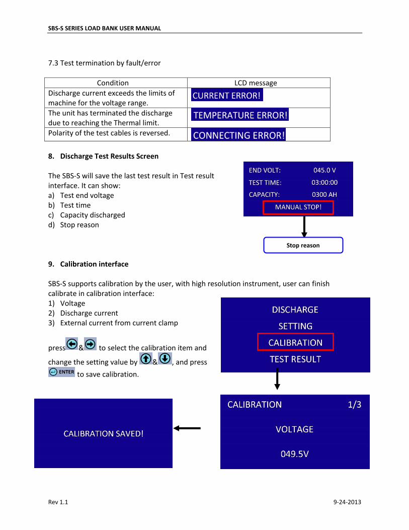
7.3 Test termination by fault/error
Condition LCD message
Discharge current exceeds the limits of machine for the voltage range.
The unit has terminated the discharge due to reaching the Thermal limit.
Polarity of the test cables is reversed.
8. Discharge Test Results Screen
The SBS-S will save the last test result in Test result interface. It can show: a) Test end voltageb) Test timec) Capacity dischargedd) Stop reason
9. Calibration interface
SBS-S supports calibration by the user, with high resolution instrument, user can finish calibrate in calibration interface: 1) Voltage2) Discharge current3) External current from current clamp
press & to select the calibration item and
change the setting value by & , and press
to save calibration.
Stop reason
SBS-S SERIES LOAD BANK USER MANUAL
Rev 1.1 9-24-2013
WARNINGS a) Please read the entire manual prior to using the test equipmentb) The tester features a number of built in safety features to allow for unmonitored operation,however, it is at the users discretion to operate the unit unmanned. c) In the event of a fault or warning during the test, an audible warning will sound and a visualwarning will be displayed. Please turn off the AC power source to avoid a further damage.
Parallel Operation The SBS S Series load banks can be operated in parallel with the SBS-8400 or another S Series load bankof the same voltage range. The External Current Clamp (SBS Part # 8400-600A) must be used to
share load information between the two load banks. Each load bank must be set up to control its
own portion of the load and must operate within its operational limits per the specifications. The master load bank where the current clamp is plugged into will display the total load current of the system when the discharge test is running.
After-Sale Service Storage Battery Systems, LLC: provides technical consulting and repair servicing for all of our battery testing equipment.
If you have any technical questions or problems, please contact us: