Embed Size (px)
Citation preview
Combiner Manual
6 to 52 Circuit Combiner Boxes
User Manual U.S. Version 2.4 DOC-CBUG-01
SBCB-6, SCCB-12, 28, 52
i

Combiner Manual
ii
Combiner Manual
iii
Copyright © 2012 SMA America, LLC. All rights reserved.
All rights reserved. No part of this document may be reproduced, stored in a retrievalsystem, or transmitted, in any form or by any means, electronic, mechanical,photographic, magnetic or otherwise, without the prior written permission of SMAAmerica, LLC.
SMA America makes no representations, express or implied, with respect to thisdocumentation or any of the equipment and/or software it may describe, including (withno limitation) any implied warranties of utility, merchantability, or fitness for any particularpurpose. All such warranties are expressly disclaimed. Neither SMA America nor itsdistributors or dealers shall be liable for any indirect, incidental, or consequential damagesunder any circumstances.
(The exclusion of implied warranties may not apply in all cases under some statutes, andthus the above exclusion may not apply.)
Specifications are subject to change without notice. Every attempt has been made tomake this document complete, accurate and up-to-date. Readers are cautioned,however, that SMA America reserves the right to make changes without notice and shallnot be responsible for any damages, including indirect, incidental or consequentialdamages, caused by reliance on the material presented, including, but not limited to,omissions, typographical errors, arithmetical errors or listing errors in the content material.
SMA America, LLC6020 West Oaks Blvd., Ste 300
Rocklin, California 95765Tel +1 916 625 0870Fax +1 916 625 0871
www.SMA-America.com
Revision HistoryRev. No. Date By Description
1.0 Nov. 1, 2004 ES / JP Preliminary Release1.1 Dec. 1, 2004 KS / JP First Release1.2 Dec. 10, 2004 JP Torque Update1.3 Feb. 09, 2005 JP Revised Specifications2.0 Feb, 2006 JP Update2.1 Jul, 23, 2007 JL Add 2.2 July 17, 2009 WZ Address Change
Drawings for all 4 models
22.4.3 September 9, 2009
February 24, 2012WZ Warranty ChangeWZ Revised Specifications
Combiner Manual
IMPORTANT SAFETY INSTRUCTIONS*SAVE THESE INSTRUCTIONS*
This manual contains important instructions for the Combiner Box models SBCB-6-90, SCCB-12-240, SCCB-28-420 and SCCB-52-416 that must be followed during the installation and use of the Combiner Boxes.
The Combiner Boxes are designed and tested according to international safety requirements, but as with all electrical and electronic equipment, certain precautions must be observed when installing the Combiner Boxes. To reduce the risk of personal injury and to ensure the safe installation and operation of the Combiner Boxes, you must carefully read and follow all instructions and warnings in this Installation Guide.
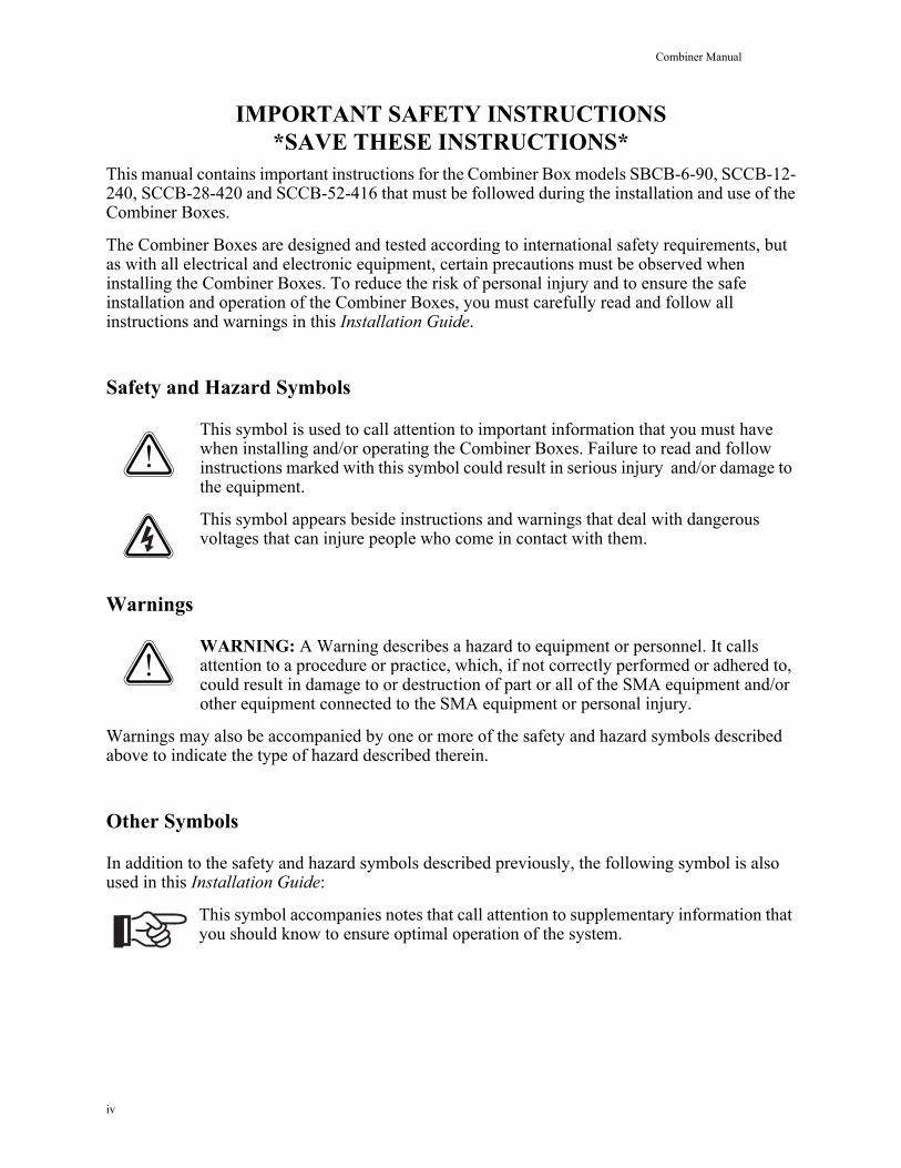
Safety and Hazard Symbols
This symbol is used to call attention to important information that you must have when installing and/or operating the Combiner Boxes. Failure to read and follow instructions marked with this symbol could result in serious injury and/or damage to the equipment.
This symbol appears beside instructions and warnings that deal with dangerous voltages that can injure people who come in contact with them.
Warnings
WARNING: A Warning describes a hazard to equipment or personnel. It calls attention to a procedure or practice, which, if not correctly performed or adhered to, could result in damage to or destruction of part or all of the SMA equipment and/or other equipment connected to the SMA equipment or personal injury.
Warnings may also be accompanied by one or more of the safety and hazard symbols described above to indicate the type of hazard described therein.
Other Symbols
In addition to the safety and hazard symbols described previously, the following symbol is also used in this Installation Guide:
This symbol accompanies notes that call attention to supplementary information that you should know to ensure optimal operation of the system.
iv
Combiner Manual
Warranty
All Combiner Boxes sold in the USA have a five-year warranty. For warranty coverage, or if you have questions about the Combiner Box warranty, contact SMA America at the address, telephone number, or Web site listed on page iii (to send E-mail, see the Contact section of the SMA America Web site: www.sma-america.com).
WARNING: All electrical installation must be done in accordance with the National Electrical Code ANSI/NFPA 70, local building codes and the requirements of the authority having jurisdiction.
WARNING:To prevent electrical shock or injury, all wiring and com-missioning procedures must be performed by qualified personnel.
WARNING: Before installing or using the Combiner Box, read all of the instructions and warnings on the Combiner Box and in this Installation Guide.
WARNING: PV arrays produce electrical energy when exposed to light and thus create an electrical shock hazard.
This GROUND symbol marks areas in the Combiner Box for connecting equipment grounds only.
v

Combiner Manual
vi
Combiner Manual Introduction
IntroductionSMA America has introduced a new line of PV combiner boxes designed for use with the SMA family of inverters.
Combiner Box features include:
• Listed to UL 1741 for the United States and Canada• Simplified input and output wiring• Compact, low-cost design• Wall-mount NEMA type 3R outdoor steel enclosure (NEMA type 4 available for SCCB-12,
SCCB-28).• Reliable bus-work for combined high current conductors
Unpacking and InspectionAll SMA Combiner Boxes are thoroughly checked before they are packaged and shipped. Although they are shipped in sturdy packaging, damage can still occur during shipping and delivery. It is important to carefully inspect the shipping container and contents prior to installation. If you detect any external damage after unpacking, report the damage immediately to your SMA dealer and shipping company that delivered the unit. If it becomes necessary to return the Combiner, use the original packing material.
If you need assistance in dealing with a damaged unit, contact SMA America at 916 625 0870.
Input Circuit ConfigurationsThe SBCB and SCCB Combiner Boxes are commonly available with 6, 12, 28 or 52 PV input circuits. Other sizes in between 6 and 52 circuits may be special ordered. Please allow sufficient lead time when custom ordering. Contact SMA America for details.
1
1 Installation Combiner Manual
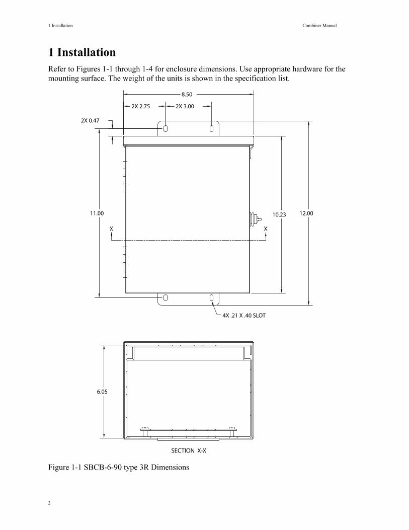
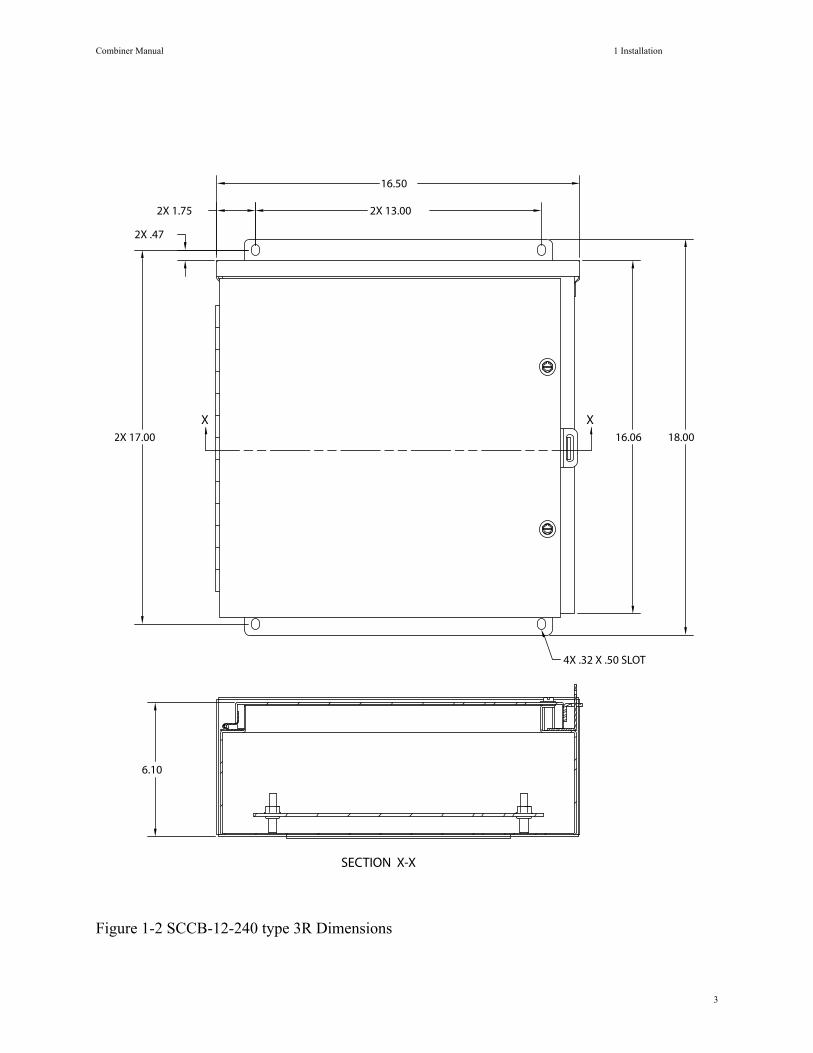
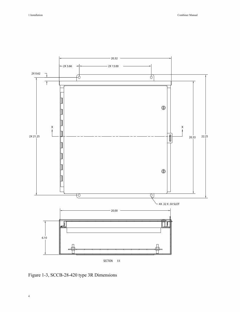
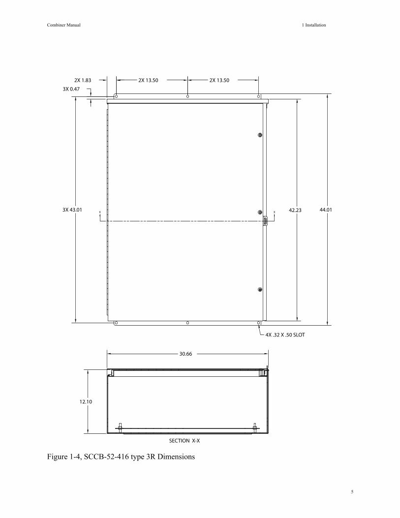
1 InstallationRefer to Figures 1-1 through 1-4 for enclosure dimensions. Use appropriate hardware for the mounting surface. The weight of the units is shown in the specification list.
Figure 1-1 SBCB-6-90 type 3R Dimensions
SECTION X-X
2X 3.002X 2.75
8.50
11.00 12.0010.23
6.05
4X .21 X .40 SLOT
X X
2X 0.47
2
Combiner Manual 1 Installation
Figure 1-2 SCCB-12-240 type 3R Dimensions
SECTION X-X
6.10
2X 13.002X 1.75
16.06 18.002X 17.00
16.50
2X .47
X X
4X .32 X .50 SLOT
3
1 Installation Combiner Manual
Figure 1-3, SCCB-28-420 type 3R Dimensions
20.32
2X 3.66 2X 13.00
XX
X-XSECTION
22.2520.332X 21.25
2X 0.62
20.00
6.10
4X .32 X .50 SLOT
4
Combiner Manual 1 Installation
Figure 1-4, SCCB-52-416 type 3R Dimensions
SECTION X-X
X X3X 43.01 42.23 44.01
2X 13.502X 1.83 2X 13.50
3X 0.47
30.66
12.10
4X .32 X .50 SLOT
5
2 Wiring Combiner Manual
2 WiringNOTE: The combiner enclosure is shipped with no entry holes. A knock-out is required for the appropriate conduit size. SMA recommends wire entry be made from the bottom, but there is no restriction, other than local code, for making wire entries from other locations in the enclosure.
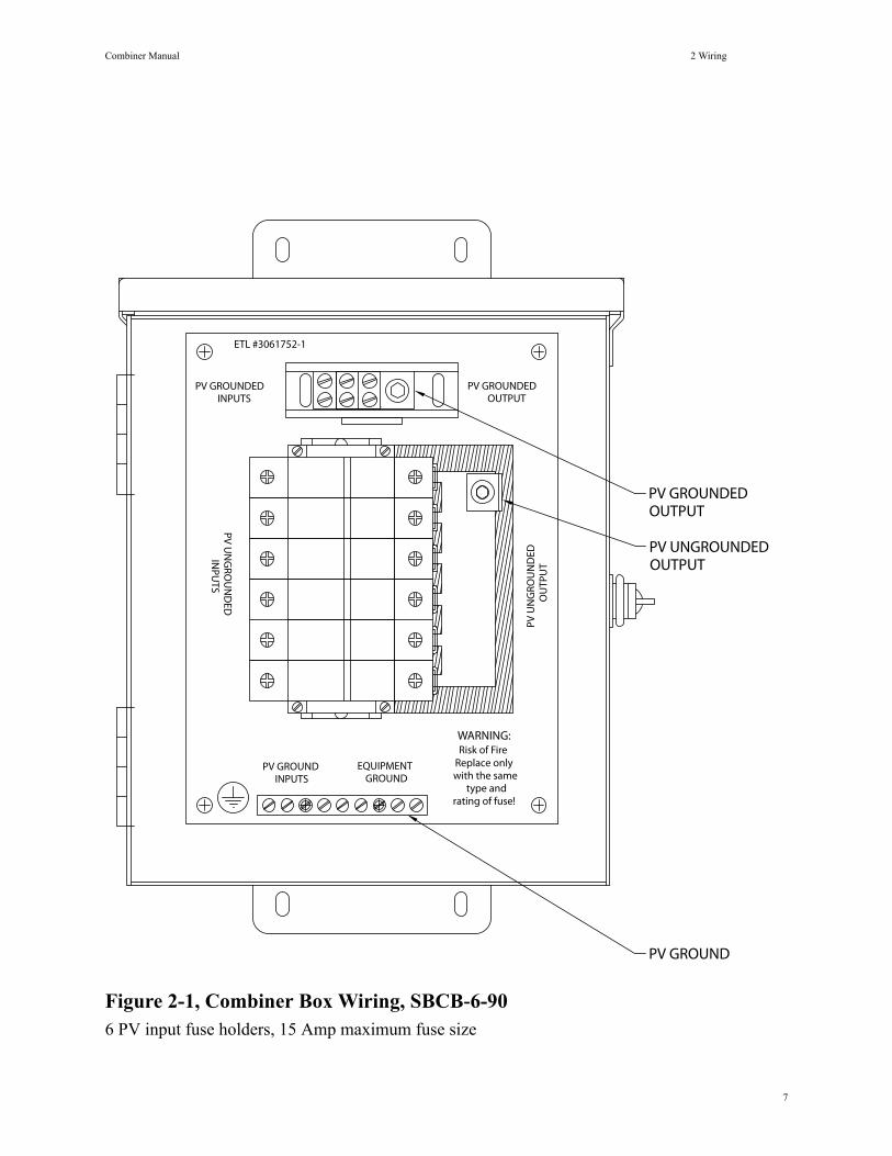
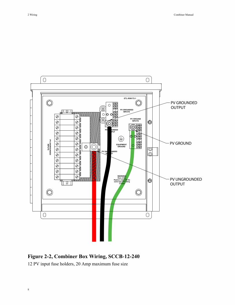
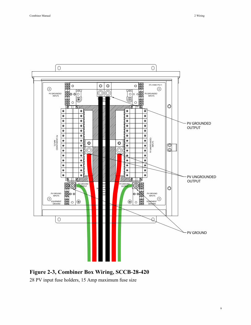
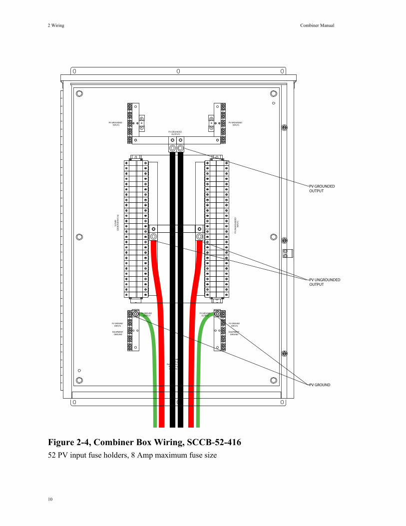
Input WiringRefer to Figures 2-1 through 2-4 for the input and output wiring locations of the combiner box. PV ungrounded conductors (positive in a negative ground system, negative in a positive ground system) are wired into the outside fuse holder terminals. PV grounded conductors (negative in a negative ground system, positive in a positive ground system) are wired into the terminal buses located at the top of the combiner box. All PV safety ground conductors are wired into the terminal busses located at the bottom of the combiner box.
Output WiringThe SBCB 6 circuit combiner box has a 90A DC fault current rating.
The SCCB 12 circuit combiner boxes has a 240A DC fault current rating.
The SCCB 28 circuit combiner boxes has a 420A DC fault current rating.
The SCCB 52 circuit combiner boxes has a 416A DC fault current rating.
When temperature and voltage drop adjustments are considered, the output conductor sizes can become quite large (500 mcm or greater) and difficult to manage. NEC 310.4 allows paralleling of conductors greater than 1/0 to achieve higher ampacities.
The SCCB-28, and 52 circuit combiner boxes provide output terminals for paralleling two conductors for the PV positive and negative, as well as the equipment ground conductors.
Combiner Box Output FusingIf more than three combiner boxes are needed for one inverter, it may be necessary to fuse the combiner box output conductors. Please contact SMA America for further details.
Refer to Figures 2-1 through 2-4 for the terminal locations of the combiner circuits.
6
Combiner Manual 2 Wiring
Figure 2-1, Combiner Box Wiring, SBCB-6-906 PV input fuse holders, 15 Amp maximum fuse size
PV U
NG
ROU
ND
EDO
UTP
UT
PV GROUNDEDOUTPUT
EQUIPMENTGROUND
PV GROUNDINPUTS
PV GROUNDEDINPUTS
PV UN
GRO
UN
DED
INPU
TS
WARNING:Risk of Fire
Replace only with the same
type and rating of fuse!
ETL #3061752-1
PV GROUNDEDOUTPUT
PV UNGROUNDEDOUTPUT
PV GROUND
7
2 Wiring Combiner Manual
Figure 2-2, Combiner Box Wiring, SCCB-12-24012 PV input fuse holders, 20 Amp maximum fuse size
WARNING:Risk of Fire
Replace only with the same type and rating
of fuse!P
V U
NG
RO
UN
DE
DIN
PU
TS
PV GROUNDEDINPUTS
PV GROUNDINPUTS
EQUIPMENTGROUND
PV GROUNDEDOUTPUT
PV UNGROUNDEDOUTPUT
ETL #306172-1
PV UNGROUNDEDOUTPUT
PV GROUND
PV GROUNDEDOUTPUT
8
Combiner Manual 2 Wiring
Figure 2-3, Combiner Box Wiring, SCCB-28-42028 PV input fuse holders, 15 Amp maximum fuse size
PV GROUNDOUTPUT
EQUIPMENTGROUND
PV GROUNDINPUTS
PV UN
GRO
UN
DED
INPU
TS
PV GROUNDEDINPUTS
PV GROUNDOUTPUT
EQUIPMENTGROUND
PV GROUNDINPUTS
PV GROUNDEDINPUTS
PV U
NG
ROU
ND
EDIN
PUTS
ETL #3061752-1
PV GROUNDEDOUTPUTS
WARNING:Risk of Fire
Replace only with the same type and rating of
fuse!
PV GROUNDEDOUTPUT
PV UNGROUNDEDOUTPUT
PV GROUND
9
2 Wiring Combiner Manual
Figure 2-4, Combiner Box Wiring, SCCB-52-41652 PV input fuse holders, 8 Amp maximum fuse size
PV GROUNDED
PV UN
GRO
UN
DED
PV GROUNDEDINPUTS
INPU
TS
INPUTS
INPU
TSPV
UN
GRO
UN
DED
INPUTSPV GROUND
PV GROUNDOUTPUT
and rating of the same type
Replace only with Risk of Fire
WARNING:
PV GROUNDOUTPUT
INPUTSPV GROUND
GROUNDEQUIPMENT
PV GROUND
PV UNGROUNDEDOUTPUT
PV GROUNDEDOUTPUT
GROUNDEQUIPMENT
PV GROUNDEDOUTPUTS
10
Combiner Manual 2 Wiring
Fuse SizingIn any electrical system, fuses are used to protect wiring and equipment from excessive currents that can cause damage, heating or in extreme cases even fire. If the fuse rating is too small it could open during normal operation. If the fuse rating is too large, it cannot provide the needed protection. In PV systems, the minimum and maximum size of the series fuse is determined by the electrical ratings of the PV module as well as by UL and National Electrical Code (NEC) requirements. Be sure to consult with your PV module manufacturer for appropriate fuse ratings.
The minimum size of fuses and wiring are calculated using the Short Circuit Current Rating (Isc) of the PV module. The NEC requires that all fuses and wiring be sized for a minimum of 1.56 times the Isc of the PV module used in the system.
The proper size PV string fuse is determined by calculating 1.56 x Isc (of the PV module) and then rounding up to the next standard fuse size.
Example: If the Isc of the PV module equals 6.9 Adc, then the fuse size is determined by 1.56 x 6.9 = 10.76. The next standard fuse size would be a 12A, 600Vdc fuse.
DC Disconnect RequirementsNEC 690.15-18 allows the use of fuse holders as a suitable means of disconnecting PV arrays for servicing. Additional DC disconnects external to the inverter may be required by the local authority having jurisdiction.
WARNING: Never open a fuse holder while it is under load. Electrical arcing and damage to the fuse holder will occur if a fuse holder is opened under load.
PV String FusesThe SBCB/SCCB is shipped without PV string fuses. SMA America maintains stock of common fuse sizes for the SBCB/SCCB products. The current rating of the fuse is dependent upon the specific PV module used in the PV array. Please contact SMA America to order the appropriate fuses for your project.
11
Specifications Combiner Manual
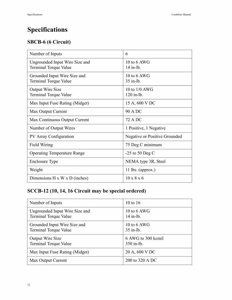
Specifications
SBCB-6 (6 Circuit)
SCCB-12 (10, 14, 16 Circuit may be special ordered)
Number of Inputs 6
Ungrounded Input Wire Size andTerminal Torque Value
10 to 6 AWG14 in-lb.
Grounded Input Wire Size and Terminal Torque Value
10 to 6 AWG35 in-lb.
Output Wire SizeTerminal Torque Value
10 to 1/0 AWG120 in-lb.
Max Input Fuse Rating (Midget) 15 A, 600 V DC
Max Output Current 90 A DC
Max Continuous Output Current 72 A DC
Number of Output Wires 1 Positive, 1 Negative
PV Array Configuration Negative or Positive Grounded
Field Wiring 75 Deg C minimum
Operating Temperature Range -25 to 50 Deg C
Enclosure Type NEMA type 3R, Steel
Weight 11 lbs. (approx.)
Dimensions H x W x D (inches) 10 x 8 x 6
Number of Inputs 10 to 16
Ungrounded Input Wire Size andTerminal Torque Value
10 to 6 AWG14 in-lb.
Grounded Input Wire Size and Terminal Torque Value
10 to 6 AWG35 in-lb.
Output Wire SizeTerminal Torque Value
6 AWG to 300 kcmil350 in-lb.
Max Input Fuse Rating (Midget) 20 A, 600 V DC
Max Output Current 200 to 320 A DC
12
Combiner Manual Specifications
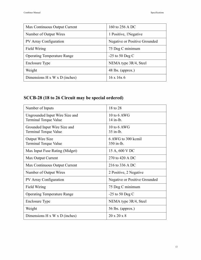
SCCB-28 (18 to 26 Circuit may be special ordered)
Max Continuous Output Current 160 to 256 A DC
Number of Output Wires 1 Positive, 1Negative
PV Array Configuration Negative or Positive Grounded
Field Wiring 75 Deg C minimum
Operating Temperature Range -25 to 50 Deg C
Enclosure Type NEMA type 3R/4, Steel
Weight 48 lbs. (approx.)
Dimensions H x W x D (inches) 16 x 16x 6
Number of Inputs 18 to 28
Ungrounded Input Wire Size andTerminal Torque Value
10 to 6 AWG14 in-lb.
Grounded Input Wire Size and Terminal Torque Value
10 to 6 AWG35 in-lb.
Output Wire SizeTerminal Torque Value
6 AWG to 300 kcmil350 in-lb.
Max Input Fuse Rating (Midget) 15 A, 600 V DC
Max Output Current 270 to 420 A DC
Max Continuous Output Current 216 to 336 A DC
Number of Output Wires 2 Positive, 2 Negative
PV Array Configuration Negative or Positive Grounded
Field Wiring 75 Deg C minimum
Operating Temperature Range -25 to 50 Deg C
Enclosure Type NEMA type 3R/4, Steel
Weight 56 lbs. (approx.)
Dimensions H x W x D (inches) 20 x 20 x 8
13
Specifications Combiner Manual
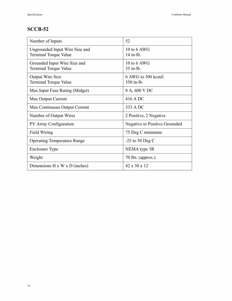
SCCB-52
Number of Inputs 52
Ungrounded Input Wire Size andTerminal Torque Value
10 to 6 AWG14 in-lb.
Grounded Input Wire Size and Terminal Torque Value
10 to 6 AWG35 in-lb.
Output Wire SizeTerminal Torque Value
6 AWG to 300 kcmil350 in-lb.
Max Input Fuse Rating (Midget) 8 A, 600 V DC
Max Output Current 416 A DC
Max Continuous Output Current 333 A DC
Number of Output Wires 2 Positive, 2 Negative
PV Array Configuration Negative or Positive Grounded
Field Wiring 75 Deg C minimum
Operating Temperature Range -25 to 50 Deg C
Enclosure Type NEMA type 3R
Weight 70 lbs. (approx.)
Dimensions H x W x D (inches) 42 x 30 x 12
14

COMBOX-UUS120824