Embed Size (px)
Citation preview
OPERATOR´S, INSTALLATION AND MAINTENANCE MANUAL
V 510
PROPELLER
P/N 068-8912.7
Edition July 30, 1988
Civil Aviation Authority CZ approved
Revision: March 2001
Manufacturer:
AVIA Propeller, Ltd. P. O. Box: 22, 250 02 Stará Boleslav
CZECH REPUBLIC
AVIA PROPELLER Ltd. V 510
MAINTENANCE MANUAL
061
(This page is intentionally left blank.)
AVIA PROPELLER Ltd. V 510
MAINTENANCE MANUAL
AIRWORTHINESS LIMITATIONS
061 Airworthiness Limitations
Page 1 1. 3. 2001
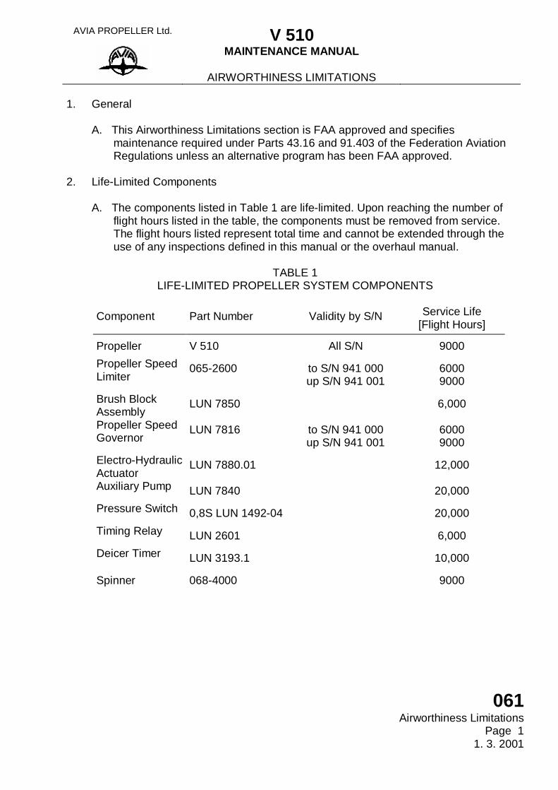
1. General A. This Airworthiness Limitations section is FAA approved and specifies maintenance required under Parts 43.16 and 91.403 of the Federation Aviation Regulations unless an alternative program has been FAA approved. 2. Life-Limited Components A. The components listed in Table 1 are life-limited. Upon reaching the number of flight hours listed in the table, the components must be removed from service. The flight hours listed represent total time and cannot be extended through the use of any inspections defined in this manual or the overhaul manual.
TABLE 1 LIFE-LIMITED PROPELLER SYSTEM COMPONENTS
Component Part Number Validity by S/N Service Life
[Flight Hours]
Propeller V 510 All S/N 9000 Propeller Speed Limiter
065-2600 to S/N 941 000 up S/N 941 001
6000 9000
Brush Block Assembly
LUN 7850 6,000
Propeller Speed Governor
LUN 7816 to S/N 941 000 up S/N 941 001
6000 9000
Electro-Hydraulic Actuator
LUN 7880.01 12,000
Auxiliary Pump LUN 7840 20,000 Pressure Switch 0,8S LUN 1492-04 20,000 Timing Relay LUN 2601 6,000 Deicer Timer LUN 3193.1 10,000
Spinner 068-4000 9000
AVIA PROPELLER Ltd. V 510
MAINTENANCE MANUAL
AIRWORTHINESS LIMITATIONS
061 Airworthiness Limitations Page 2 1. 3. 2001
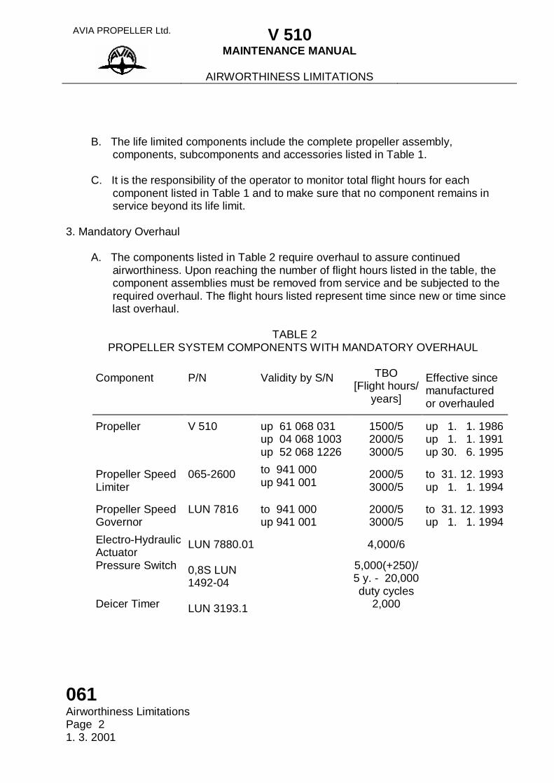
B. The life limited components include the complete propeller assembly, components, subcomponents and accessories listed in Table 1. C. It is the responsibility of the operator to monitor total flight hours for each component listed in Table 1 and to make sure that no component remains in service beyond its life limit. 3. Mandatory Overhaul A. The components listed in Table 2 require overhaul to assure continued airworthiness. Upon reaching the number of flight hours listed in the table, the component assemblies must be removed from service and be subjected to the required overhaul. The flight hours listed represent time since new or time since last overhaul.
TABLE 2 PROPELLER SYSTEM COMPONENTS WITH MANDATORY OVERHAUL
Component P/N Validity by S/N TBO
[Flight hours/ years]
Effective since manufactured or overhauled
Propeller V 510 up 61 068 031 up 04 068 1003 up 52 068 1226
1500/5 2000/5 3000/5
up 1. 1. 1986 up 1. 1. 1991 up 30. 6. 1995
Propeller Speed Limiter
065-2600 to 941 000 up 941 001
2000/5 3000/5
to 31. 12. 1993 up 1. 1. 1994
Propeller Speed Governor
LUN 7816 to 941 000 up 941 001
2000/5 3000/5
to 31. 12. 1993 up 1. 1. 1994
Electro-Hydraulic Actuator
LUN 7880.01 4,000/6
Pressure Switch 0,8S LUN 1492-04
5,000(+250)/ 5 y. - 20,000 duty cycles
Deicer Timer LUN 3193.1 2,000
AVIA PROPELLER Ltd. V 510
MAINTENANCE MANUAL
AIRWORTHINESS LIMITATIONS
061 Airworthiness Limitations
Page 3 1. 3. 2001
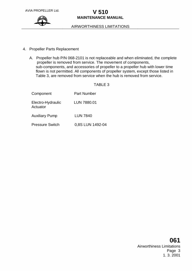
4. Propeller Parts Replacement A. Propeller hub P/N 068-2101 is not replaceable and when eliminated, the complete propeller is removed from service. The movement of components, sub-components, and accessories of propeller to a propeller hub with lower time flown is not permitted. All components of propeller system, except those listed in Table 3, are removed from service when the hub is removed from service.
TABLE 3 Component Part Number Electro-Hydraulic LUN 7880.01 Actuator Auxiliary Pump LUN 7840 Pressure Switch 0,8S LUN 1492-04
AVIA PROPELLER Ltd. V 510
MAINTENANCE MANUAL
AIRWORTHINESS LIMITATIONS
061 Airworthiness Limitations Page 4 1. 3. 2001
(This page is intentionally left blank.)
AVIA PROPELLER Ltd. V 510
MAINTENANCE MANUAL AIRWORTHINESS LIMITATIONS
VALID FOR CANADA ONLY
061 Airworthiness Limitations valid for Canada only
Page 1 1. 3. 2001
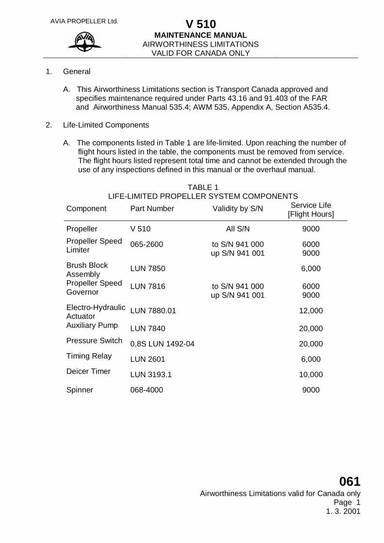
1. General A. This Airworthiness Limitations section is Transport Canada approved and specifies maintenance required under Parts 43.16 and 91.403 of the FAR and Airworthiness Manual 535.4; AWM 535, Appendix A, Section A535.4. 2. Life-Limited Components A. The components listed in Table 1 are life-limited. Upon reaching the number of flight hours listed in the table, the components must be removed from service. The flight hours listed represent total time and cannot be extended through the use of any inspections defined in this manual or the overhaul manual.
TABLE 1 LIFE-LIMITED PROPELLER SYSTEM COMPONENTS
Component Part Number Validity by S/N Service Life [Flight Hours]
Propeller V 510 All S/N 9000 Propeller Speed Limiter
065-2600 to S/N 941 000 up S/N 941 001
6000 9000
Brush Block Assembly
LUN 7850 6,000
Propeller Speed Governor
LUN 7816 to S/N 941 000 up S/N 941 001
6000 9000
Electro-Hydraulic Actuator
LUN 7880.01 12,000
Auxiliary Pump LUN 7840 20,000 Pressure Switch 0,8S LUN 1492-04 20,000 Timing Relay LUN 2601 6,000 Deicer Timer LUN 3193.1 10,000
Spinner 068-4000 9000
AVIA PROPELLER Ltd. V 510
MAINTENANCE MANUAL AIRWORTHINESS LIMITATIONS
VALID FOR CANADA ONLY
061 Airworthiness Limitations valid for Canada only Page 2 1. 3. 2001
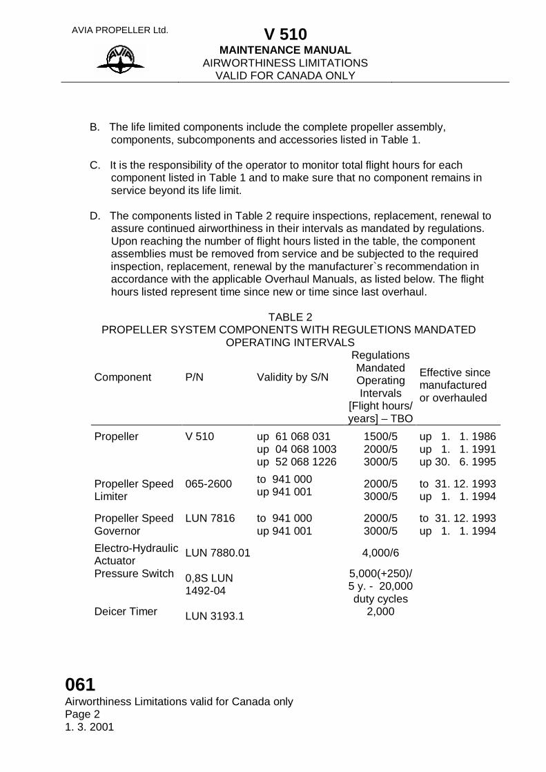
B. The life limited components include the complete propeller assembly, components, subcomponents and accessories listed in Table 1. C. It is the responsibility of the operator to monitor total flight hours for each component listed in Table 1 and to make sure that no component remains in service beyond its life limit. D. The components listed in Table 2 require inspections, replacement, renewal to assure continued airworthiness in their intervals as mandated by regulations. Upon reaching the number of flight hours listed in the table, the component assemblies must be removed from service and be subjected to the required inspection, replacement, renewal by the manufacturer`s recommendation in accordance with the applicable Overhaul Manuals, as listed below. The flight hours listed represent time since new or time since last overhaul.
TABLE 2 PROPELLER SYSTEM COMPONENTS WITH REGULETIONS MANDATED
OPERATING INTERVALS Component
P/N
Validity by S/N
Regulations Mandated Operating Intervals
[Flight hours/ years] – TBO
Effective since manufactured or overhauled
Propeller V 510 up 61 068 031 up 04 068 1003 up 52 068 1226
1500/5 2000/5 3000/5
up 1. 1. 1986 up 1. 1. 1991 up 30. 6. 1995
Propeller Speed Limiter
065-2600 to 941 000 up 941 001
2000/5 3000/5
to 31. 12. 1993 up 1. 1. 1994
Propeller Speed Governor
LUN 7816 to 941 000 up 941 001
2000/5 3000/5
to 31. 12. 1993 up 1. 1. 1994
Electro-Hydraulic Actuator
LUN 7880.01 4,000/6
Pressure Switch 0,8S LUN 1492-04
5,000(+250)/ 5 y. - 20,000 duty cycles
Deicer Timer LUN 3193.1 2,000
AVIA PROPELLER Ltd. V 510
MAINTENANCE MANUAL AIRWORTHINESS LIMITATIONS
VALID FOR CANADA ONLY
061 Airworthiness Limitations valid for Canada only
Page 3 1. 3. 2001
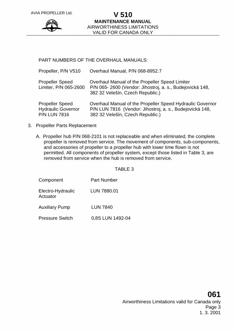
PART NUMBERS OF THE OVERHAUL MANUALS: Propeller, P/N V510 Overhaul Manual, P/N 068-8952.7 Propeller Speed Overhaul Manual of the Propeller Speed Limiter Limiter, P/N 065-2600 P/N 065- 2600 (Vendor: Jihostroj, a. s., Budejovická 148, 382 32 Velešín, Czech Republic.) Propeller Speed Overhaul Manual of the Propeller Speed Hydraulic Governor Hydraulic Governor P/N LUN 7816 (Vendor: Jihostroj, a. s., Budejovická 148, P/N LUN 7816 382 32 Velešín, Czech Republic.) 3. Propeller Parts Replacement A. Propeller hub P/N 068-2101 is not replaceable and when eliminated, the complete propeller is removed from service. The movement of components, sub-components, and accessories of propeller to a propeller hub with lower time flown is not permitted. All components of propeller system, except those listed in Table 3, are removed from service when the hub is removed from service.
TABLE 3 Component Part Number Electro-Hydraulic LUN 7880.01 Actuator Auxiliary Pump LUN 7840 Pressure Switch 0,8S LUN 1492-04
AVIA PROPELLER Ltd. V 510
MAINTENANCE MANUAL AIRWORTHINESS LIMITATIONS
VALID FOR CANADA ONLY
061 Airworthiness Limitations valid for Canada only Page 4 1. 3. 2001
(This page is intentionally left blank.)
AVIA PROPELLER Ltd. V 510
MAINTENANCE MANUAL SECTION 061
061 List of Amendments
Page 1 30. 6. 1999
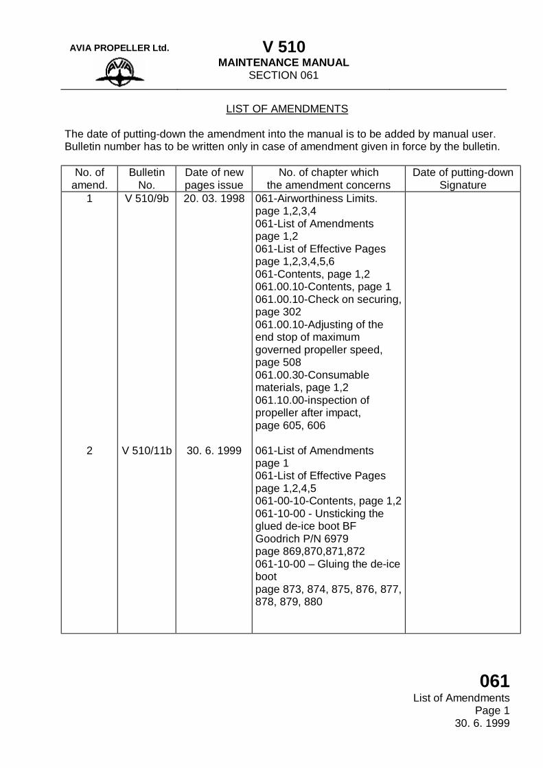
LIST OF AMENDMENTS
The date of putting-down the amendment into the manual is to be added by manual user. Bulletin number has to be written only in case of amendment given in force by the bulletin.
No. of amend.
Bulletin No.
Date of new pages issue
No. of chapter which the amendment concerns
Date of putting-down Signature
1
2
V 510/9b
V 510/11b
20. 03. 1998
30. 6. 1999
061-Airworthiness Limits. page 1,2,3,4 061-List of Amendments page 1,2 061-List of Effective Pages page 1,2,3,4,5,6 061-Contents, page 1,2 061.00.10-Contents, page 1 061.00.10-Check on securing, page 302 061.00.10-Adjusting of the end stop of maximum governed propeller speed, page 508 061.00.30-Consumable materials, page 1,2 061.10.00-inspection of propeller after impact, page 605, 606 061-List of Amendments page 1 061-List of Effective Pages page 1,2,4,5 061-00-10-Contents, page 1,2 061-10-00 - Unsticking the glued de-ice boot BF Goodrich P/N 6979 page 869,870,871,872 061-10-00 – Gluing the de-ice boot page 873, 874, 875, 876, 877, 878, 879, 880
AVIA PROPELLER Ltd. V 510
MAINTENANCE MANUAL SECTION 061 PROPELLER
061 List of Amendments Page 2 1. 3. 2001
LIST OF AMENDMENTS (Continued) No. of
amend. Bulletin
No. Date of new pages issue
No. of chapter which the amendment concerns
Date of putting-down Signature
3 V 510/1a 1. 3. 2001 Front page 061 Airworthiness Limits. page 1-3 061 Airworthiness Limits. Valid for Canada Only page1-3 061 List of Amendments page 2,3 061 List of Effective Pages page 1,2,3,4,5,6 061 Table of Contents page 1 061-00-00 General page 1,2 061-00-10 Contents page 1 061-00-10 Specification - Function page 0-i 061-00-10 Troubleshooting page 100-i 061-00-10 Servicing in Operation page 300-i 061-00-10 Adjustment - Testing page 500-i 061-00-10 page 501, 502, 503, 504 061-00-10 Inspection - Checking page 600-i 061-00-10 - Current Repairs page 800-i 061-10-00 Contents page 1,2 061-10-00 Specification - Function page 0-i 061-10-00 Troubleshooting page 100-i 061-10-00 Servicing in Operation page 300-i 061-10-00 Installation - Removal page 400-i
AVIA PROPELLER Ltd. V 510
MAINTENANCE MANUAL SECTION 061 PROPELLER
061 List of Amendments
Page 3 1. 3. 2001
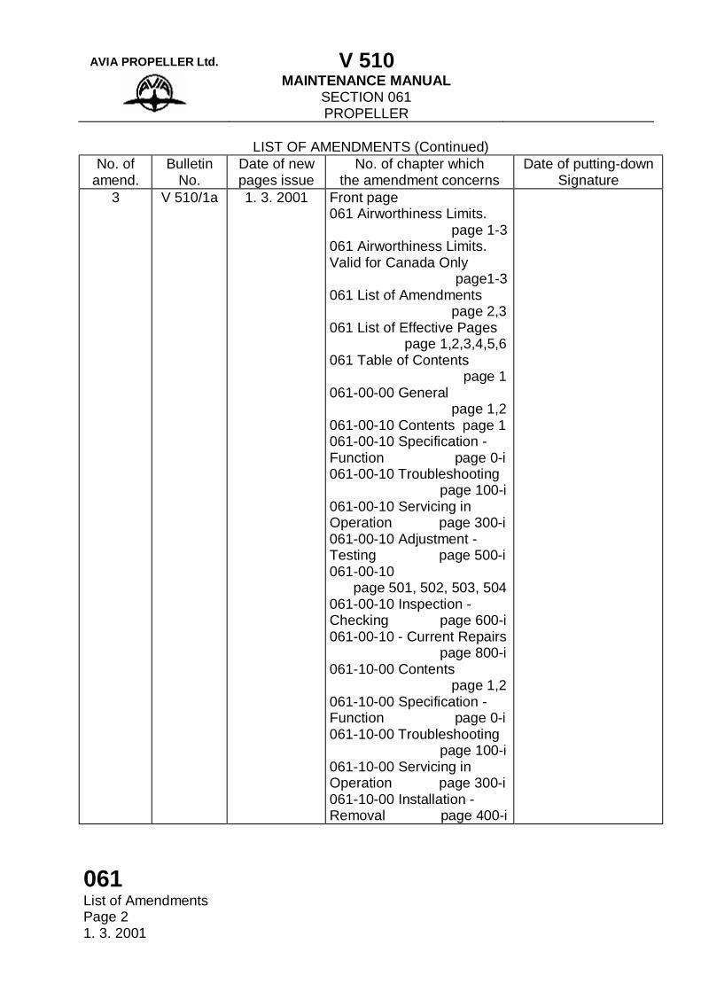
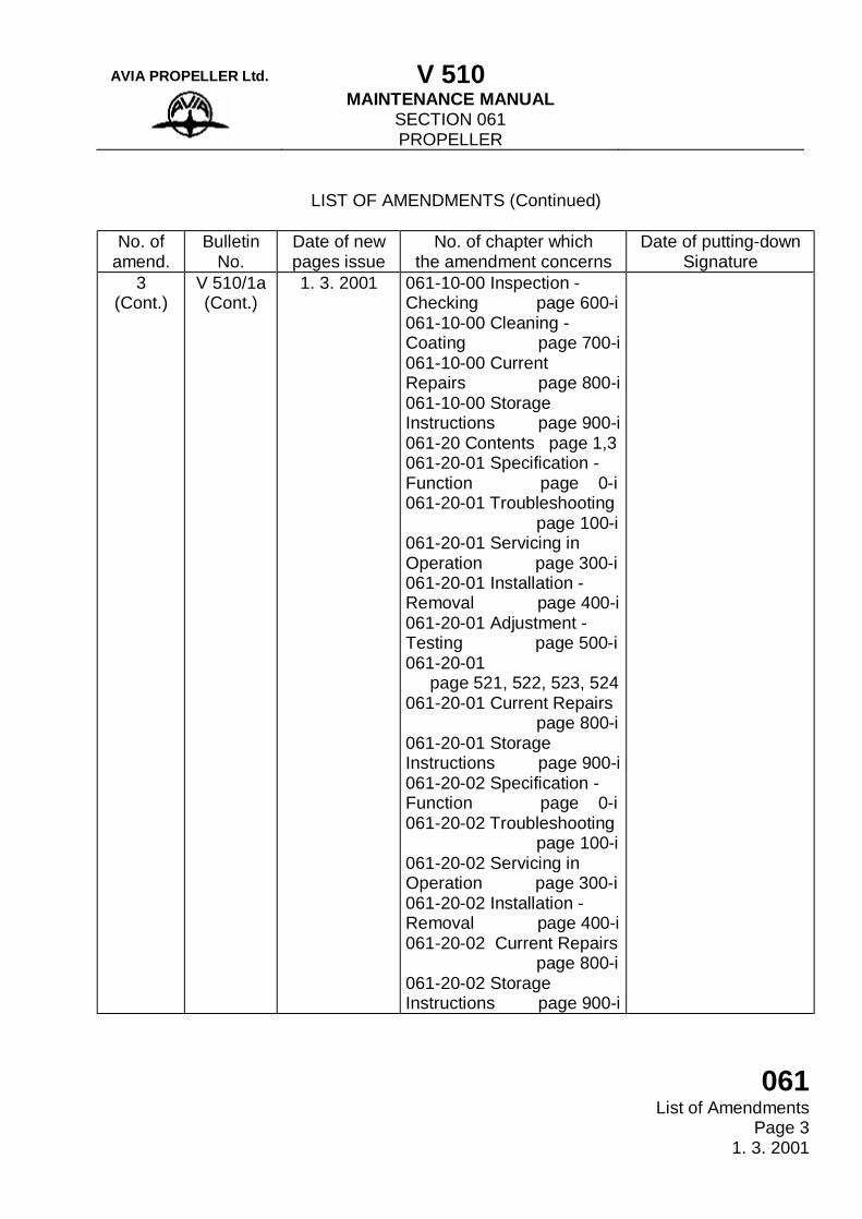
LIST OF AMENDMENTS (Continued)
No. of
amend. Bulletin
No. Date of new pages issue
No. of chapter which the amendment concerns
Date of putting-down Signature
3 (Cont.)
V 510/1a (Cont.)
1. 3. 2001 061-10-00 Inspection - Checking page 600-i 061-10-00 Cleaning - Coating page 700-i 061-10-00 Current Repairs page 800-i 061-10-00 Storage Instructions page 900-i 061-20 Contents page 1,3 061-20-01 Specification - Function page 0-i 061-20-01 Troubleshooting page 100-i 061-20-01 Servicing in Operation page 300-i 061-20-01 Installation - Removal page 400-i 061-20-01 Adjustment - Testing page 500-i 061-20-01 page 521, 522, 523, 524 061-20-01 Current Repairs page 800-i 061-20-01 Storage Instructions page 900-i 061-20-02 Specification - Function page 0-i 061-20-02 Troubleshooting page 100-i 061-20-02 Servicing in Operation page 300-i 061-20-02 Installation - Removal page 400-i 061-20-02 Current Repairs page 800-i 061-20-02 Storage Instructions page 900-i
AVIA PROPELLER Ltd. V 510
MAINTENANCE MANUAL SECTION 061 PROPELLER
061 List of Amendments Page 4 1. 3. 2001
(This page is intentionally left blank.)
AVIA PROPELLER Ltd. V 510
MAINTENANCE MANUAL SECTION 061 PROPELLER
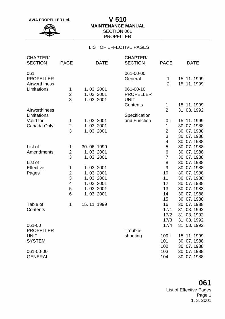
061 List of Effective Pages
Page 1 1. 3. 2001
LIST OF EFFECTIVE PAGES CHAPTER/ SECTION
PAGE
DATE
CHAPTER/ SECTION
PAGE
DATE
061 PROPELLER Airworthiness Limitations Airworthiness Limitations Valid for Canada Only List of Amendments List of Effective Pages Table of Contents 061-00 PROPELLER UNIT SYSTEM 061-00-00 GENERAL
1 2 3 1 2 3 1 2 3 1 2 3 4 5 6 1
1. 03. 2001 1. 03. 2001 1. 03. 2001 1. 03. 2001 1. 03. 2001 1. 03. 2001 30. 06. 1999 1. 03. 2001 1. 03. 2001 1. 03. 2001 1. 03. 2001 1. 03. 2001 1. 03. 2001 1. 03. 2001 1. 03. 2001 15. 11. 1999
061-00-00 General 061-00-10 PROPELLER UNIT Contents Specification and Function Trouble-shooting
1 2 1 2 0-i 1 2 3 4 5 6 7 8 9 10 11 12 13 14 15 16 17/1 17/2 17/3 17/4 100-i 101 102 103 104
15. 11. 1999 15. 11. 1999 15. 11. 1999 31. 03. 1992 15. 11. 1999 30. 07. 1988 30. 07. 1988 30. 07. 1988 30. 07. 1988 30. 07. 1988 30. 07. 1988 30. 07. 1988 30. 07. 1988 30. 07. 1988 30. 07. 1988 30. 07. 1988 30. 07. 1988 30. 07. 1988 30. 07. 1988 30. 07. 1988 30. 07. 1988 31. 03. 1992 31. 03. 1992 31. 03. 1992 31. 03. 1992 15. 11. 1999 30. 07. 1988 30. 07. 1988 30. 07. 1988 30. 07. 1988
AVIA PROPELLER Ltd. V 510
MAINTENANCE MANUAL SECTION 061 PROPELLER
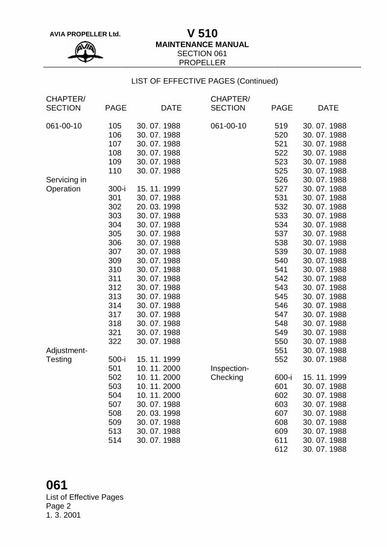
061 List of Effective Pages Page 2 1. 3. 2001
LIST OF EFFECTIVE PAGES (Continued) CHAPTER/ SECTION
PAGE
DATE
CHAPTER/ SECTION
PAGE
DATE
061-00-10 Servicing in Operation Adjustment- Testing
105 106 107 108 109 110 300-i 301 302 303 304 305 306 307 309 310 311 312 313 314 317 318 321 322 500-i 501 502 503 504 507 508 509 513 514
30. 07. 1988 30. 07. 1988 30. 07. 1988 30. 07. 1988 30. 07. 1988 30. 07. 1988 15. 11. 1999 30. 07. 1988 20. 03. 1998 30. 07. 1988 30. 07. 1988 30. 07. 1988 30. 07. 1988 30. 07. 1988 30. 07. 1988 30. 07. 1988 30. 07. 1988 30. 07. 1988 30. 07. 1988 30. 07. 1988 30. 07. 1988 30. 07. 1988 30. 07. 1988 30. 07. 1988 15. 11. 1999 10. 11. 2000 10. 11. 2000 10. 11. 2000 10. 11. 2000 30. 07. 1988 20. 03. 1998 30. 07. 1988 30. 07. 1988 30. 07. 1988
061-00-10 Inspection- Checking
519 520 521 522 523 525 526 527 531 532 533 534 537 538 539 540 541 542 543 545 546 547 548 549 550 551 552 600-i 601 602 603 607 608 609 611 612
30. 07. 1988 30. 07. 1988 30. 07. 1988 30. 07. 1988 30. 07. 1988 30. 07. 1988 30. 07. 1988 30. 07. 1988 30. 07. 1988 30. 07. 1988 30. 07. 1988 30. 07. 1988 30. 07. 1988 30. 07. 1988 30. 07. 1988 30. 07. 1988 30. 07. 1988 30. 07. 1988 30. 07. 1988 30. 07. 1988 30. 07. 1988 30. 07. 1988 30. 07. 1988 30. 07. 1988 30. 07. 1988 30. 07. 1988 30. 07. 1988 15. 11. 1999 30. 07. 1988 30. 07. 1988 30. 07. 1988 30. 07. 1988 30. 07. 1988 30. 07. 1988 30. 07. 1988 30. 07. 1988
AVIA PROPELLER Ltd. V 510
MAINTENANCE MANUAL SECTION 061 PROPELLER
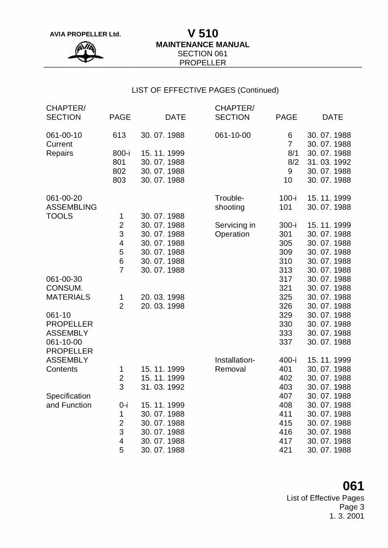
061 List of Effective Pages
Page 3 1. 3. 2001
LIST OF EFFECTIVE PAGES (Continued)
CHAPTER/ SECTION
PAGE
DATE
CHAPTER/ SECTION
PAGE
DATE
061-00-10 Current Repairs 061-00-20 ASSEMBLING TOOLS 061-00-30 CONSUM. MATERIALS 061-10 PROPELLER ASSEMBLY 061-10-00 PROPELLER ASSEMBLY Contents Specification and Function
613 800-i 801 802 803 1 2 3 4 5 6 7 1 2 1 2 3 0-i 1 2 3 4 5
30. 07. 1988 15. 11. 1999 30. 07. 1988 30. 07. 1988 30. 07. 1988 30. 07. 1988 30. 07. 1988 30. 07. 1988 30. 07. 1988 30. 07. 1988 30. 07. 1988 30. 07. 1988 20. 03. 1998 20. 03. 1998 15. 11. 1999 15. 11. 1999 31. 03. 1992 15. 11. 1999 30. 07. 1988 30. 07. 1988 30. 07. 1988 30. 07. 1988 30. 07. 1988
061-10-00 Trouble-shooting Servicing in Operation Installation- Removal
6 7 8/1 8/2 9 10 100-i 101 300-i 301 305 309 310 313 317 321 325 326 329 330 333 337 400-i 401 402 403 407 408 411 415 416 417 421
30. 07. 1988 30. 07. 1988 30. 07. 1988 31. 03. 1992 30. 07. 1988 30. 07. 1988 15. 11. 1999 30. 07. 1988 15. 11. 1999 30. 07. 1988 30. 07. 1988 30. 07. 1988 30. 07. 1988 30. 07. 1988 30. 07. 1988 30. 07. 1988 30. 07. 1988 30. 07. 1988 30. 07. 1988 30. 07. 1988 30. 07. 1988 30. 07. 1988 15. 11. 1999 30. 07. 1988 30. 07. 1988 30. 07. 1988 30. 07. 1988 30. 07. 1988 30. 07. 1988 30. 07. 1988 30. 07. 1988 30. 07. 1988 30. 07. 1988
AVIA PROPELLER Ltd. V 510
MAINTENANCE MANUAL SECTION 061 PROPELLER
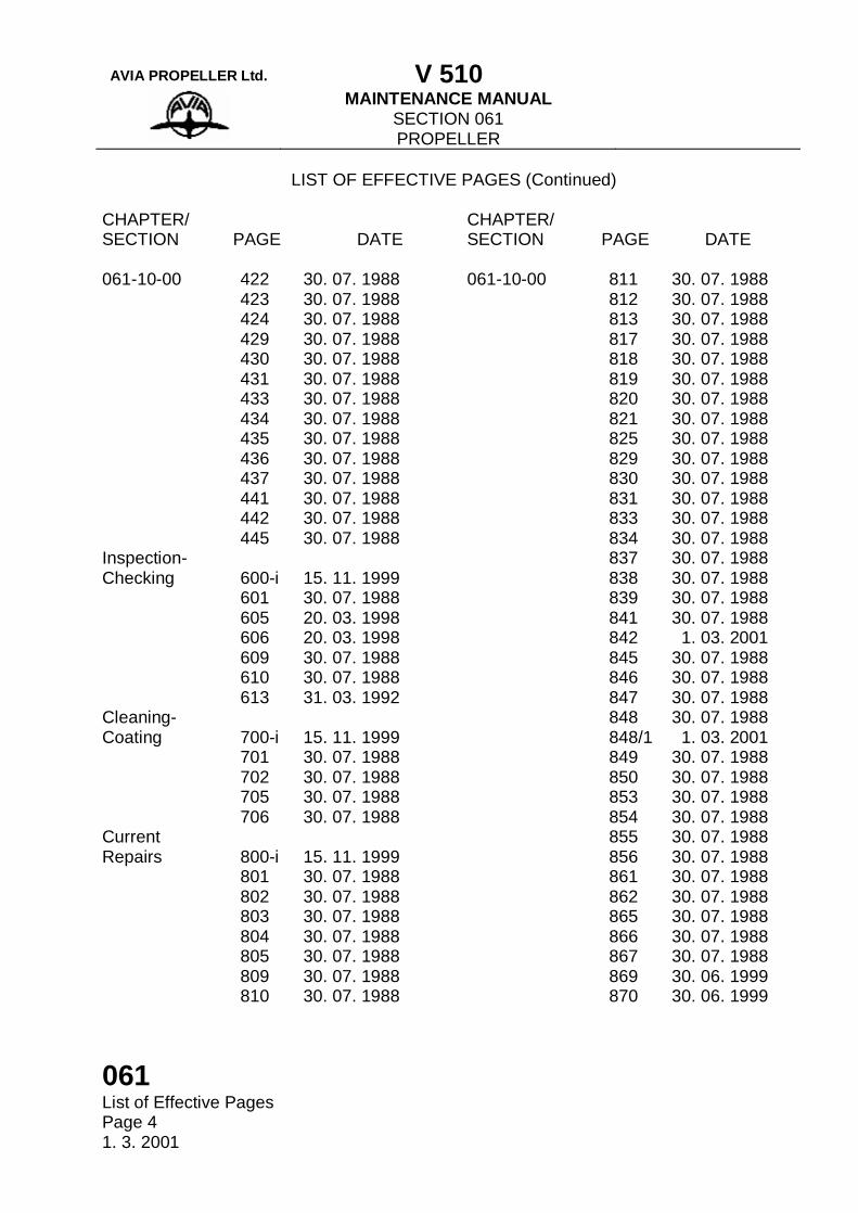
061 List of Effective Pages Page 4 1. 3. 2001
LIST OF EFFECTIVE PAGES (Continued) CHAPTER/ SECTION
PAGE
DATE
CHAPTER/ SECTION
PAGE
DATE
061-10-00 Inspection- Checking Cleaning- Coating Current Repairs
422 423 424 429 430 431 433 434 435 436 437 441 442 445 600-i 601 605 606 609 610 613 700-i 701 702 705 706 800-i 801 802 803 804 805 809 810
30. 07. 1988 30. 07. 1988 30. 07. 1988 30. 07. 1988 30. 07. 1988 30. 07. 1988 30. 07. 1988 30. 07. 1988 30. 07. 1988 30. 07. 1988 30. 07. 1988 30. 07. 1988 30. 07. 1988 30. 07. 1988 15. 11. 1999 30. 07. 1988 20. 03. 1998 20. 03. 1998 30. 07. 1988 30. 07. 1988 31. 03. 1992 15. 11. 1999 30. 07. 1988 30. 07. 1988 30. 07. 1988 30. 07. 1988 15. 11. 1999 30. 07. 1988 30. 07. 1988 30. 07. 1988 30. 07. 1988 30. 07. 1988 30. 07. 1988 30. 07. 1988
061-10-00
811 812 813 817 818 819 820 821 825 829 830 831 833 834 837 838 839 841 842 845 846 847 848 848/1 849 850 853 854 855 856 861 862 865 866 867 869 870
30. 07. 1988 30. 07. 1988 30. 07. 1988 30. 07. 1988 30. 07. 1988 30. 07. 1988 30. 07. 1988 30. 07. 1988 30. 07. 1988 30. 07. 1988 30. 07. 1988 30. 07. 1988 30. 07. 1988 30. 07. 1988 30. 07. 1988 30. 07. 1988 30. 07. 1988 30. 07. 1988 1. 03. 2001 30. 07. 1988 30. 07. 1988 30. 07. 1988 30. 07. 1988 1. 03. 2001 30. 07. 1988 30. 07. 1988 30. 07. 1988 30. 07. 1988 30. 07. 1988 30. 07. 1988 30. 07. 1988 30. 07. 1988 30. 07. 1988 30. 07. 1988 30. 07. 1988 30. 06. 1999 30. 06. 1999
AVIA PROPELLER Ltd. V 510
MAINTENANCE MANUAL SECTION 061 PROPELLER
061 List of Effective Pages
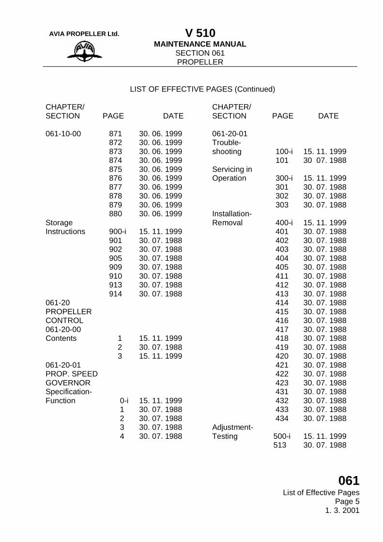
Page 5 1. 3. 2001
LIST OF EFFECTIVE PAGES (Continued)
CHAPTER/ SECTION
PAGE
DATE
CHAPTER/ SECTION
PAGE
DATE
061-10-00 Storage Instructions 061-20 PROPELLER CONTROL 061-20-00 Contents 061-20-01 PROP. SPEED GOVERNOR Specification- Function
871 872 873 874 875 876 877 878 879 880 900-i 901 902 905 909 910 913 914 1 2 3 0-i 1 2 3 4
30. 06. 1999 30. 06. 1999 30. 06. 1999 30. 06. 1999 30. 06. 1999 30. 06. 1999 30. 06. 1999 30. 06. 1999 30. 06. 1999 30. 06. 1999 15. 11. 1999 30. 07. 1988 30. 07. 1988 30. 07. 1988 30. 07. 1988 30. 07. 1988 30. 07. 1988 30. 07. 1988 15. 11. 1999 30. 07. 1988 15. 11. 1999 15. 11. 1999 30. 07. 1988 30. 07. 1988 30. 07. 1988 30. 07. 1988
061-20-01 Trouble-shooting Servicing in Operation Installation- Removal Adjustment- Testing
100-i 101 300-i 301 302 303 400-i 401 402 403 404 405 411 412 413 414 415 416 417 418 419 420 421 422 423 431 432 433 434 500-i 513
15. 11. 1999 30 07. 1988 15. 11. 1999 30. 07. 1988 30. 07. 1988 30. 07. 1988 15. 11. 1999 30. 07. 1988 30. 07. 1988 30. 07. 1988 30. 07. 1988 30. 07. 1988 30. 07. 1988 30. 07. 1988 30. 07. 1988 30. 07. 1988 30. 07. 1988 30. 07. 1988 30. 07. 1988 30. 07. 1988 30. 07. 1988 30. 07. 1988 30. 07. 1988 30. 07. 1988 30. 07. 1988 30. 07. 1988 30. 07. 1988 30. 07. 1988 30. 07. 1988 15. 11. 1999 30. 07. 1988
AVIA PROPELLER Ltd. V 510
MAINTENANCE MANUAL SECTION 061 PROPELLER
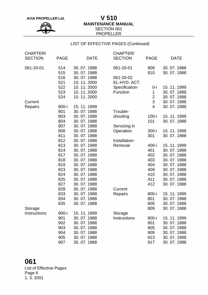
061 List of Effective Pages Page 6 1. 3. 2001
LIST OF EFFECTIVE PAGES (Continued) CHAPTER/ SECTION
PAGE
DATE
CHAPTER/ SECTION
PAGE
DATE
061-20-01 Current Repairs Storage Instructions
514 515 516 521 522 523 524 800-i 801 803 804 807 808 811 812 813 814 817 818 819 823 824 825 827 828 833 834 835 900-i 901 902 903 904 905 907
30. 07. 1988 30. 07. 1988 30. 07. 1988 10. 11. 2000 10. 11. 2000 10. 11. 2000 10. 11. 2000 15. 11. 1999 30. 07. 1988 30. 07. 1988 30. 07. 1988 30. 07. 1988 30. 07. 1988 30. 07. 1988 30. 07. 1988 30. 07. 1988 30. 07. 1988 30. 07. 1988 30. 07. 1988 30. 07. 1988 30. 07. 1988 30. 07. 1988 30. 07. 1988 30. 07. 1988 30. 07. 1988 30. 07. 1988 30. 07. 1988 30. 07. 1988 15. 11. 1999 30. 07. 1988 30. 07. 1988 30. 07. 1988 30. 07. 1988 30. 07. 1988 30. 07. 1988
061-20-01 061-20-02 EL-HYD. ACT. Specification- Function Trouble-shooting Servicing in Operation Installation- Removal Current Repairs Storage Instructions
909 910 0-i 1 2 3 4 100-i 101 300-i 301 400-i 401 402 403 404 409 410 411 412 800-i 801 805 809 900-i 901 905 909 913 917
30. 07. 1988 30. 07. 1988 15. 11. 1999 30. 07. 1988 30. 07. 1988 30. 07. 1988 30. 07. 1988 15. 11. 1999 30. 07. 1988 15. 11. 1999 30. 07. 1988 15. 11. 1999 30. 07. 1988 30. 07. 1988 30. 07. 1988 30. 07. 1988 30. 07. 1988 30. 07. 1988 30. 07. 1988 30. 07. 1988 15. 11. 1999 30. 07. 1988 30. 07. 1988 30. 07. 1988 15. 11. 1999 30. 07. 1988 30. 07. 1988 30. 07. 1988 30. 07. 1988 30. 07. 1988
AVIA PROPELLER Ltd. V 510
MAINTENANCE MANUAL SECTION 061 PROPELLER
061 Table of Contents
Page 1 15. 11. 1999
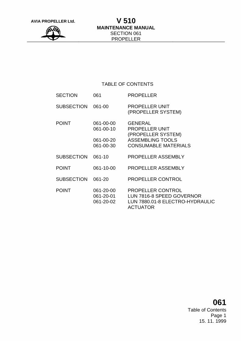
TABLE OF CONTENTS
SECTION SUBSECTION POINT SUBSECTION POINT SUBSECTION POINT
061 061-00 061-00-00 061-00-10 061-00-20 061-00-30 061-10 061-10-00 061-20 061-20-00 061-20-01 061-20-02
PROPELLER PROPELLER UNIT (PROPELLER SYSTEM) GENERAL PROPELLER UNIT (PROPELLER SYSTEM) ASSEMBLING TOOLS CONSUMABLE MATERIALS PROPELLER ASSEMBLY PROPELLER ASSEMBLY PROPELLER CONTROL PROPELLER CONTROL LUN 7816-8 SPEED GOVERNOR LUN 7880.01-8 ELECTRO-HYDRAULIC ACTUATOR
AVIA PROPELLER Ltd. V 510
MAINTENANCE MANUAL SECTION 061 PROPELLER
061 Table of Contents Page 2 15. 11. 1999
(This page is intentionally left blank)
AVIA PROPELLER Ltd. V 510
MAINTENANCE MANUAL GENERAL
061-00-00 General Page 1
15. 11. 1999
Operator´s, Installation and Maintenance Manual of V 510 Propeller, P/N 068-8912.7 is worked out acc. to the GOST 18675-73 standard and ATA 100 standard. It contains technical description and hints concerning the operation and the maintenance of the propeller. Specified work and period of servicing, time of overhaul and life of instruments are given in the special „Maintenance Requirements Manual“ P/N 068-8942.7. For L-410 UVP-E and L 420 aeroplanes, specified work and period of servicing, time of overhaul and life of instruments are given in the „Aircraft Maintenance Manual“. This manual, in some cases, also contains references to the „Aircraft Operation Manual“, or of the engine „Maintenance Manual“, and to the „Wiring diagram album of the aeroplane L 410 UVP-E“ or L 420 respectively. The propeller servicing is included in the „Aircraft Operation Manual“. Division of the manual The manual is divided into subsections and points. This division represented by numerical notation given on the external margin of the page. Example: 061 - 10 - 00 ------------------------ section (propeller) ----------------- subsection (propeller assembly) ----------- point Every subsection possesses an independent numbering of pages. The number of a page also contains a coded internal division of every subsection in themes of work to be realized which contributes to easier orientation and also enables to carry out changes. Block of pages are numbered as follows: SPECIFICATION AND FUNCTION 1 to 99 TROUBLESHOOTING 100 to 199 Technology of servicing SERVICING IN OPERATION 300 to 399 INSTALLATION - REMOVAL 400 to 499 ADJUSTMENT - TESTING 500 to 599 INSPECTION - CHECKING 600 to 699 CLEANING - COATING 700 to 799 CURRENT REPAIRS 800 to 899 STORAGE INSTRUCTION 900 to 999
AVIA PROPELLER Ltd. V 510
MAINTENANCE MANUAL GENERAL
061-00-00 General Page 2 15. 11. 1999
Illustrations The numbering of illustrations is independent in every subsection. In the themes the numbering of illustrations is similar to the numbering of pages i.e.: SPECIFICATION AND FUNCTION 1 to 99 INSTALLATION - REMOVAL 400 to 499, etc. PRELIMINARY REPAIRS The user can be informed on the change to be prepared for this Operator`s, Installation and Maintenance Manual in advance, before the edition of replacing sheets, by obtaining a special sheet „Preliminary Repairs“. This sheet is filed by the user opposite to the correspondent sheet of this Operator`s, Installation and Maintenance Manual. After the new corrected sheet is introduced, the original sheet inclusively the sheet „Preliminary Repairs“ are put out from the manual. The numbering of „Preliminary Repairs“ is independet in every chapter. For instance, in the chapter 061 - Propeller, the first „Prelimiary Repair“ will carry number 061.1. AUTORIZATION TO PERFORM WORK Work cited in the working procedures of this manual is to be performed only by specialists meeting gualifications according to aviation authority prescriptions (i.e. in Czech Republic prescriptions of the Civil Aviation Authority - CAA are valid) and carrying full responsibility for performing complete work of necessary quality. WARNING: 1) BEFORE THE BEGINNING OF THE ORDERED WORK, THE SPECIALIST IS OBLIGED TO BECOME ACQUAINTED WITH THE WORKING PROCEDURE OF THE DESTINED WORK AND FURTHER CONNECTING INSTRUCTIONS, IF CITED IN THE WORKING PROCEDURES OF THIS MANUAL. IT IS NEEDED TO MAKE READY NECESSARY TOOLS AND PRESCRIBED MATERIAL ACCORDING TO ALL PROCEDURES CONCERNING THE WORK. 2) THE COLUMN „WORKING EXPENSES (STANDARD HOURS)“ IS TO BE COMPLETED BY THE USER ACCORDING TO HIS OWN WORKING CONDITIONS AND EXPERIENCES. THE NUMBER OF WORKING HOURS GIVEN ABOVE SHOULD ALSO CONTAIN TIME OF WORK PERFORMED IN THE PROCEDURE IN QUESTION. CAUTION 1) LIST THE TITLES AND PART NUMBERS OF THE ADDITIONAL ASSOCIATED PROCEDURES NEEDED TO PERFORM PROPELLER MAINTENANCE - SEE CHAPTER 061, AIRWORTHINESS LIMITATIONS VALID FOR CANADA ONLY, PAGE 2, PARAGRAPH D.
AVIA PROPELLER Ltd. V 510
MAINTENANCE MANUAL PROPELLER UNIT
(PROPELLER SYSTEM)
061-00-10 Contents
Page 1 15. 11. 1999
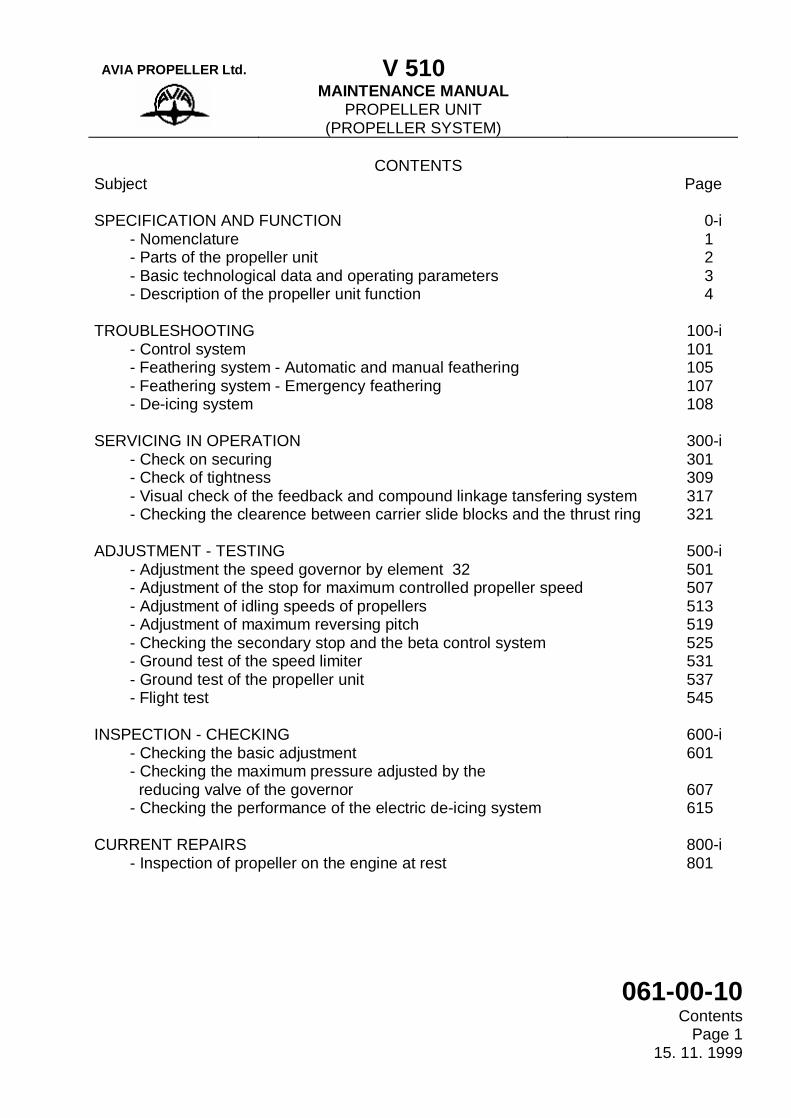
CONTENTS Subject Page SPECIFICATION AND FUNCTION - Nomenclature - Parts of the propeller unit - Basic technological data and operating parameters - Description of the propeller unit function TROUBLESHOOTING - Control system - Feathering system - Automatic and manual feathering - Feathering system - Emergency feathering - De-icing system SERVICING IN OPERATION - Check on securing - Check of tightness - Visual check of the feedback and compound linkage tansfering system - Checking the clearence between carrier slide blocks and the thrust ring ADJUSTMENT - TESTING - Adjustment the speed governor by element 32 - Adjustment of the stop for maximum controlled propeller speed - Adjustment of idling speeds of propellers - Adjustment of maximum reversing pitch - Checking the secondary stop and the beta control system - Ground test of the speed limiter - Ground test of the propeller unit - Flight test INSPECTION - CHECKING - Checking the basic adjustment - Checking the maximum pressure adjusted by the reducing valve of the governor - Checking the performance of the electric de-icing system CURRENT REPAIRS - Inspection of propeller on the engine at rest
0-i 1 2 3 4 100-i 101 105 107 108 300-i 301 309 317 321 500-i 501 507 513 519 525 531 537 545 600-i 601 607 615 800-i 801
AVIA PROPELLER Ltd. V 510
MAINTENANCE MANUAL PROPELLER UNIT
(PROPELLER SYSTEM)
061-00-10 Contents Page 2 31. 03. 1992
LIST OF FIGURES
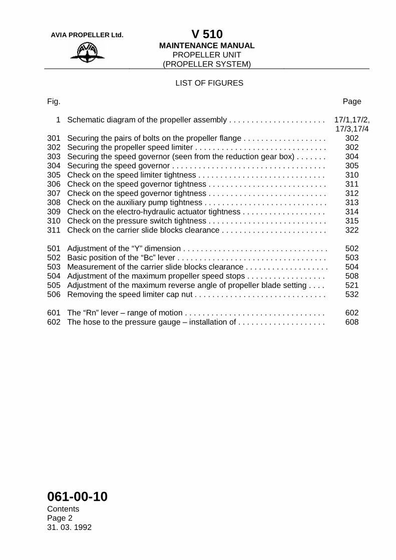
Fig. Page 1 Schematic diagram of the propeller assembly . . . . . . . . . . . . . . . . . . . . . . 301 Securing the pairs of bolts on the propeller flange . . . . . . . . . . . . . . . . . . . 302 Securing the propeller speed limiter . . . . . . . . . . . . . . . . . . . . . . . . . . . . . . 303 Securing the speed governor (seen from the reduction gear box) . . . . . . . 304 Securing the speed governor . . . . . . . . . . . . . . . . . . . . . . . . . . . . . . . . . . . 305 Check on the speed limiter tightness . . . . . . . . . . . . . . . . . . . . . . . . . . . . . 306 Check on the speed governor tightness . . . . . . . . . . . . . . . . . . . . . . . . . . . 307 Check on the speed governor tightness . . . . . . . . . . . . . . . . . . . . . . . . . . . 308 Check on the auxiliary pump tightness . . . . . . . . . . . . . . . . . . . . . . . . . . . . 309 Check on the electro-hydraulic actuator tightness . . . . . . . . . . . . . . . . . . . 310 Check on the pressure switch tightness . . . . . . . . . . . . . . . . . . . . . . . . . . . 311 Check on the carrier slide blocks clearance . . . . . . . . . . . . . . . . . . . . . . . . 501 Adjustment of the “Y” dimension . . . . . . . . . . . . . . . . . . . . . . . . . . . . . . . . . 502 Basic position of the “Bc” lever . . . . . . . . . . . . . . . . . . . . . . . . . . . . . . . . . . 503 Measurement of the carrier slide blocks clearance . . . . . . . . . . . . . . . . . . . 504 Adjustment of the maximum propeller speed stops . . . . . . . . . . . . . . . . . . 505 Adjustment of the maximum reverse angle of propeller blade setting . . . . 506 Removing the speed limiter cap nut . . . . . . . . . . . . . . . . . . . . . . . . . . . . . . 601 The “Rn” lever – range of motion . . . . . . . . . . . . . . . . . . . . . . . . . . . . . . . . 602 The hose to the pressure gauge – installation of . . . . . . . . . . . . . . . . . . . .
17/1,17/2, 17/3,17/4
302 302 304 305 310 311 312 313 314 315 322
502 503 504 508 521 532
602 608
AVIA PROPELLER Ltd. V 510
MAINTENANCE MANUAL PROPELLER UNIT
/PROPELLER SYSTEM/
061-00-10 Specification and Function
Page Block 0 - i 15. 11. 1999
SPECIFICATION - FUNCTION The following page block provides information about overall layout, parts, basic technological data, description and operating parameters.
AVIA PROPELLER Ltd. V 510
MAINTENANCE MANUAL PROPELLER UNIT
/PROPELLER SYSTEM/
061-00-10 Specification and Function Page Block 0 - ii 15. 11. 1999
(This page is intentionally left blank)
AVIA PROPELLER Ltd. V 510
MAINTENANCE MANUAL PROPELLER UNIT
/PROPELLER SYSTEM/
061-00-10 Troubleshooting
Page Block 100 - i 15. 11. 1999
TROUBLESHOOTING The following page block provides information needed to perform troubleshooting of the propeller unit control system and feathering system. Using the tables provided, determine probable causes and remedies for problems encountered.

AVIA PROPELLER Ltd. V 510
MAINTENANCE MANUAL PROPELLER UNIT
/PROPELLER SYSTEM/
061-00-10 Troubleshooting Page Block 100 - ii 15. 11. 1999
(This page is intentionally left blank)
AVIA PROPELLER Ltd. V 510
MAINTENANCE MANUAL PROPELLER UNIT
/PROPELLER SYSTEM/
061-00-10 Servicing in Operation
Page Block 300 - i 15. 11. 1999
SERVICING IN OPERATION The following page block provides information needed when performing the works, which might occur during the operation, e.g. after installation of the propeller unit instruments, always before starting the engines and during the periodical maintenance.

AVIA PROPELLER Ltd. V 510
MAINTENANCE MANUAL PROPELLER UNIT
/PROPELLER SYSTEM/
061-00-10 Servicing in Operation Page Block 300 – ii 15. 11. 1999
(This page is intentionally left blank)
AVIA PROPELLER Ltd. V 510
MAINTENANCE MANUAL PROPELLER UNIT
/PROPELLER SYSTEM/
061-00-10 Adjustment-Testing Page Block 500 – i
15. 11. 1999
ADJUSTMENT - TESTING The following page block provides information needed when performing the basic adjustment of the adjustable elements of propeller after installation on the engine or in case of propeller replacement, when performing the installation of the new engine or when installing the other instruments of the propeller unit and during the periodical maintenance. There are further here provided the procedures for checking the parameters during the engine test and after previous interventions into the facility, including the instruction for carrying out the checking of the functional properties of the propeller unit in flight.
AVIA PROPELLER Ltd. V 510
MAINTENANCE MANUAL PROPELLER UNIT
/PROPELLER SYSTEM/
061-00-10 Adjustment-Testing Page Block 500 - ii
15. 11. 1999
(This page is intentionally left blank)
AVIA PROPELLER Ltd. V 510
MAINTENANCE MANUAL PROPELLER UNIT
/PROPELLER SYSTEM/
061-00-10 Adjustment-Testing
Page 501 10. 11. 2000
L 410 UVP-E MAINTENANCE SCHEDULE
WORK PROCEDURE
On pages 501- 504
REFERENCE No.
For:
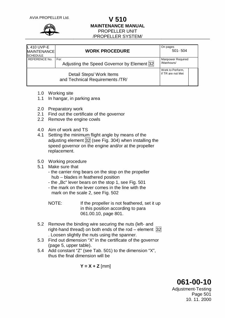
Adjusting the Speed Governor by Element 32
Manpower Required /Manhours/
Detail Steps/ Work Items
and Technical Requirements /TR/
Work to Perform, if TR are not Met
1.0 Working site 1.1 In hangar, in parking area
2.0 Preparatory work 2.1 Find out the certificate of the governor 2.2 Remove the engine cowls 4.0 Aim of work and TS 4.1 Setting the minimum flight angle by means of the
adjusting element 32 (see Fig. 304) when installing the speed governor on the engine and/or at the propeller replacement.
5.0 Working procedure 5.1 Make sure that - the carrier ring bears on the stop on the propeller hub – blades in feathered position - the „Bc“ lever bears on the stop 1, see Fig. 501 - the mark on the lever comes in the line with the mark on the scale 2, see Fig. 502
NOTE: If the propeller is not feathered, set it up
in this position according to para 061.00.10, page 801.
5.2 Remove the binding wire securing the nuts (left- and
right-hand thread) on both ends of the rod – element 32 . Loosen slightly the nuts using the spanner.
5.3 Find out dimension “X” in the certificate of the governor (page 5, upper table).
5.4 Add constant “Z” (see Tab. 501) to the dimension “X”, thus the final dimension will be
Y = X + Z [mm]
AVIA PROPELLER Ltd. V 510
MAINTENANCE MANUAL PROPELLER UNIT
/PROPELLER SYSTEM/
061-00-10 Adjustment-Testing Page 502 10. 11. 2000
Detail Steps/Work Items and Technical Requirements /TR/
Work to perform if TR are not Met
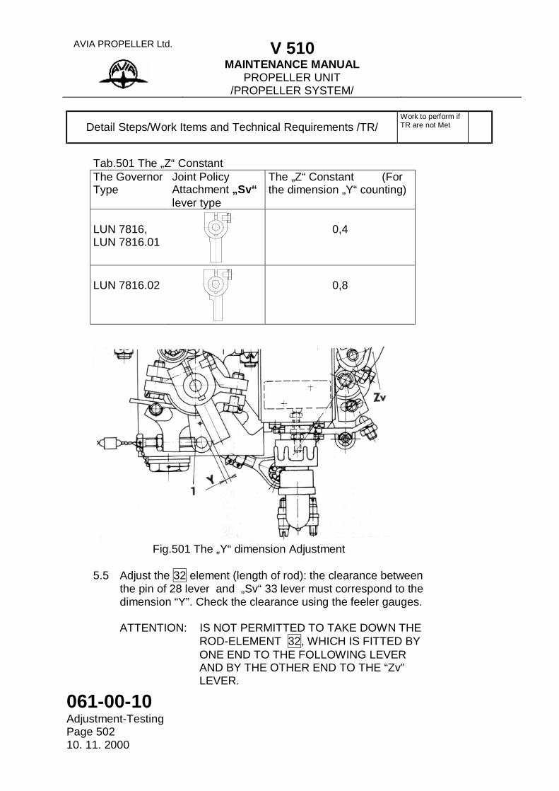
Tab.501 The „Z“ Constant The Governor Type
Joint Policy Attachment „Sv“ lever type
The „Z“ Constant (For the dimension „Y“ counting)
LUN 7816, LUN 7816.01
0,4
LUN 7816.02
0,8
Fig.501 The „Y“ dimension Adjustment
5.5 Adjust the 32 element (length of rod): the clearance between
the pin of 28 lever and „Sv“ 33 lever must correspond to the dimension “Y”. Check the clearance using the feeler gauges.
ATTENTION: IS NOT PERMITTED TO TAKE DOWN THE
ROD-ELEMENT 32, WHICH IS FITTED BY ONE END TO THE FOLLOWING LEVER AND BY THE OTHER END TO THE “Zv” LEVER.
AVIA PROPELLER Ltd. V 510
MAINTENANCE MANUAL PROPELLER UNIT
/PROPELLER SYSTEM/
061-00-10 Adjustment-Testing
Page 503 10. 11. 2000
Detail Steps/Work Items and Technical Requirements /TR/
Work to perform if TR are not Met
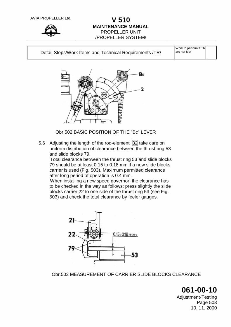
Obr.502 BASIC POSITION OF THE ”Bc” LEVER 5.6 Adjusting the length of the rod-element 32 take care on
uniform distribution of clearance between the thrust ring 53 and slide blocks 79.
Total clearance between the thrust ring 53 and slide blocks 79 should be at least 0.15 to 0.18 mm if a new slide blocks carrier is used (Fig. 503). Maximum permitted clearance after long period of operation is 0.4 mm.
When installing a new speed governor, the clearance has to be checked in the way as follows: press slightly the slide blocks carrier 22 to one side of the thrust ring 53 (see Fig. 503) and check the total clearance by feeler gauges.
Obr.503 MEASUREMENT OF CARRIER SLIDE BLOCKS CLEARANCE
AVIA PROPELLER Ltd. V 510
MAINTENANCE MANUAL PROPELLER UNIT
/PROPELLER SYSTEM/
061-00-10 Adjustment-Testing Page 504 10. 11. 2000
Detail Steps/Work Items and Technical Requirements /TR/
Work to perform if TR are not Met
5.7 After final adjustment and measurement of the clearance
on the slide blocks carrier, tighten both nuts of the rod-element 32 using spanner (see Fig. 501 – left and right hand thread) and secure carefully according to para 061.20.01, page 431.
6.0 Final operations 6.1 Install the engine cowls as far as you do not continue
installation of a new speed governor according to para 061.20.01, page 411).
6.2 Test according to para 061.00.10, page 537, 545, 601. 7.0 Record in documents. 7.1 Put down a record in the governor cetificate.
Feeler gauges Side wire nippers Stainless binding wire 0,05 to 1,0x100 mm Flat pliers 0,5 mm diameter Double-ended wrench 8x10
mm
Stairs Z 37.9514-00 or B 097 300 N
AVIA PROPELLER Ltd. V 510
MAINTENANCE MANUAL PROPELLER UNIT
/PROPELLER SYSTEM/
061-00-10 Inspection-Checking
Page Block 600 - i 15. 11. 1999
INSPECTION - CHECKING The following page block provides information needed for checking on the basic control adjustment and instruments function.
AVIA PROPELLER Ltd. V 510
MAINTENANCE MANUAL PROPELLER UNIT
/PROPELLER SYSTEM/
061-00-10 Inspection-Checking Page Block 600 - ii 15. 11. 1999
(This page is intentionally left blank)
AVIA PROPELLER Ltd. V 510
MAINTENANCE MANUAL PROPELLER UNIT
/PROPELLER SYSTEM/
061-00-10 Current Repairs
Page Block 800 - i 15. 11. 1999
CURRENT REPAIRS The following page block provides information concerning the performing of the common activities in course of operation, e. g. replacement of the replaceable elements, retightening the sealing elements, renewal of function or repair of minor damage.
AVIA PROPELLER Ltd. V 510
MAINTENANCE MANUAL PROPELLER UNIT
/PROPELLER SYSTEM/
061-00-10 Current Repairs Page Block 800 – ii 15. 11. 1999
(This page is intentionally left blank)
AVIA PROPELLER Ltd. V 510
MAINTENANCE MANUAL PROPELLER ASSEMBLY
061-10-00 Contents
Page 1 15. 11. 1999
CONTENTS
Subject Page SPECIFICATION AND FUNCTION - Generally - Basic technological data - Description - Packing of the propeller TROUBLESHOOTING - Troubleshooting SERVICING IN OPERATION - Checking of tightness of joints - Checking the propeller blades - Checking the position of thrust ring - Checking the spinner attachment - Checking the contact rings - Checking securing of bolted joints - Propeller servicing - Checking the connecting conductors - Checking of securing of all locked joints - Inspection of propeller spinner and cover INSTALLATION - REMOVAL - Removing the propeller from engine - Removing the propeller blades - Dismantling of connecting conductors - Removing the propeller head from the engine - Installing the propeller head on the engine - Installing the propeller blades - Installing the connecting conductors - Installing the earth conductor - Installing the spinner INSPECTION - CHECKING - Inspection of propeller after overspeeding - Inspection of propeller after impact - Checking the depth of damage on propeller blades - Propeller inspection following the lightning stroke
0-i 1 2 3 6 100-i 101 300-i 301 305 309 313 317 321 325 329 333 337 400-i 401 407 411 415 421 429 433 441 445 600-i 601 605 609 613
AVIA PROPELLER Ltd. V 510
MAINTENANCE MANUAL PROPELLER ASSEMBLY
061-10-00 Contents Page 2 15. 11. 1999
CONTENTS (Continued)
Subject Page CLEANING - COATING - Repair the damaged coating on propeller spinner - Repair of damaged coating on propeller blade CURRENT REPAIRS - Repair of propeller blades - Repair of heater surface coating - Repair of loosened spots on the heater surface - Replacement of electric de-icing system connecting cable - Repair of connecting conductor contacts - Repair of propeller spinner - Repair of transfer rings - Replacement of packing of external ring on the blade root - Replacement the blade root packing - Replacement of transfer rings or propeller cover - Airscrew ballancing - Replacement of speed limiter - Torque wrench UMO 10 - Unsticking the glued de-ice boot BF Goodrich P/N 6979 - Gluing the de-ice boot STORAGE INSTRUCTIONS - Instruction for storage - Propeller preservation at aeroplane storage throught 30 days - Propeller preservation at aeroplane storage throught 3 months - Propeller preservation at aeroplane storage for a time longer than 3 months
700-i 701 705 800-i 801 809 817 825 829 833 837 841 845 849 853 861 865 869 873 900-i 901 905 909 913
AVIA PROPELLER Ltd. V 510
MAINTENANCE MANUAL PROPELLER ASSEMBLY
061-10-00 Specification and Function
Page Block 0 - i 15. 11. 1999
SPECIFICATION - FUNCTION The following page block provides information about overall layout, parts, basic technological data, description and operating parameters.

AVIA PROPELLER Ltd. V 510
MAINTENANCE MANUAL PROPELLER ASSEMBLY
061-10-00 Specification and Function Page Block 0 – ii 15. 11. 1999
(This page is intentionally left blank)
AVIA PROPELLER Ltd. V 510
MAINTENANCE MANUAL PROPELLER ASSEMBLY
061-10-00 Troubleshooting
Page Block 100 - i 15. 11. 1999
TROUBLESHOOTING The following page block provides information needed to perform troubleshooting of the propeller unit control system and feathering system. Using the tables provided, determine probable causes and remedies for problems encountered.
AVIA PROPELLER Ltd. V 510
MAINTENANCE MANUAL PROPELLER ASSEMBLY
061-10-00 Troubleshooting Page Block 100 – ii 15. 11. 1999
(This page is intentionally left blank)
AVIA PROPELLER Ltd. V 510
MAINTENANCE MANUAL PROPELLER ASSEMBLY
061-10-00 Servicing in Operation
Page Block 300 - i 15. 11. 1999
SERVICING IN OPERATION The following page block provides information needed when performing the works, which might occur during the operation, e.g. after installation of the propeller unit instruments, always before starting the engines and during the periodical maintenance.

AVIA PROPELLER Ltd. V 510
MAINTENANCE MANUAL PROPELLER ASSEMBLY
061-10-00 Servicing in Operation Page Block 300 – ii 15. 11. 1999
(This page is intentionally left blank)
AVIA PROPELLER Ltd. V 510
MAINTENANCE MANUAL PROPELLER ASSEMBLY
061-10-00 Installation-Removal
Page Block 400 - i 15. 11. 1999
INSTALLATION - REMOVAL The following page block provides information needed when performing the installation of the propeller on the engine or of components of the former and removal of the propeller from the engine including the components of the former.

AVIA PROPELLER Ltd. V 510
MAINTENANCE MANUAL PROPELLER ASSEMBLY
061-10-00 Installation-Removal Page Block 400 – ii 15. 11. 1999
(This page is intentionally left blank)
AVIA PROPELLER Ltd. V 510
MAINTENANCE MANUAL PROPELLER ASSEMBLY
061-10-00 Inspection-Checking
Page Block 600 – i 15. 11. 1999
INSPECTION - CHECKING The following page block provides information needed for checking on the basic control adjustment and instruments function.
AVIA PROPELLER Ltd. V 510
MAINTENANCE MANUAL PROPELLER ASSEMBLY
061-10-00 Inspection-Checking Page Block 600 - ii 15. 11. 1999
(This page is intentionally left blank)
AVIA PROPELLER Ltd. V 510
MAINTENANCE MANUAL PROPELLER ASSEMBLY
061-10-00 Cleaning-Coating
Page Block 700 - i 15. 11. 1999
CLEANING - COATING The following page block provides information needed for cleaning the propeller components and for renewal of the surface protection by means of painting.

AVIA PROPELLER Ltd. V 510
MAINTENANCE MANUAL PROPELLER ASSEMBLY
061-10-00 Cleaning-Coating Page Block 700 - ii 15. 11. 1999
(This page is intentionally left blank)
AVIA PROPELLER Ltd. V 510
MAINTENANCE MANUAL PROPELLER ASSEMBLY
061-10-00 Current Repairs
Page Block 800 - i 15. 11. 1999
CURRENT REPAIRS The following page block provides information concerning the performing of the common activities in course of operation, e. g. replacement of the replaceable elements, retightening the sealing elements, renewal of function or repair of minor damage.
AVIA PROPELLER Ltd. V 510
MAINTENANCE MANUAL PROPELLER ASSEMBLY
061-10-00 Current Repairs Page Block 800 - ii 15. 11. 1999
(This page is intentionally left blank)
AVIA PROPELLER Ltd. V 510
MAINTENANCE MANUAL PROPELLER ASSEMBLY
061-10-00 Current Repairs
Page 841 30. 07. 1988
WORK PROCEDURE
On pages 841 - 842
L 410 UVP-E MAINTENANCE SCHEDULE REFERENCE No.
For: Replacement of packing of external ring on the blade root
Manpower Required /Manhours/
Detail Steps/ Work Items and Technical Requirements /TR/
Work to Perform, if TR are not Met
1.0 Working site 1.1 In hangar, in parking area
2.0 Preparatory work 2.1 Remove 20 screws from the surface of the spinner and
shift the spinner out. 5.0 Working procedure 5.1 Remove the connecting conductor from the sleeve
according to par.. 061.10.00, page 411 and remove the propeller blade according to par. 061.10.00, page 407.
5.2 Unlock and screw of the nut 11 and pull it out incl. the lock washer across the sleeve and put aside. Using a sharp object, for example a needle, remove the defective packing 44.
5.3 Clean sealed surfaces, lubricate them by oil and put in the new packing.
5.4 Fit on the lock washer 43 and the nut 11. Tighten the nut by torque 150 Nm and further up to the nearest tooth of the lock washer; secure the nut.
5.5 Install the airscrew blade according to par. 061.10.00, page 429 and the connecting conductor on the sleeve according to par. 061.10.00, page 433.
AVIA PROPELLER Ltd. V 510
MAINTENANCE MANUAL PROPELLER ASSEMBLY
061-10-00 Current Repairs Page 842 1. 3. 2001
Detail Steps/Work Items and Technical Requirements /TR/
Work to perform, if TR are not Met
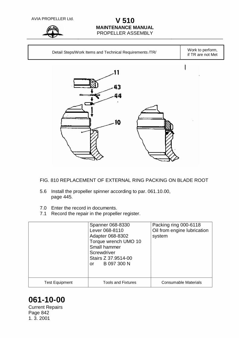
FIG. 810 REPLACEMENT OF EXTERNAL RING PACKING ON BLADE ROOT 5.6 Install the propeller spinner according to par. 061.10.00,
page 445. 7.0 Enter the record in documents. 7.1 Record the repair in the propeller register.
Spanner 068-8330 Packing ring 000-6118 Lever 068-8110 Oil from engine lubrication Adapter 068-8302 system Torque wrench UMO 10 Small hammer Screwdriver Stairs Z 37.9514-00 or B 097 300 N
Test Equipment Tools and Fixtures Consumable Materials
AVIA PROPELLER Ltd. V 510
MAINTENANCE MANUAL PROPELLER ASSEMBLY
061-10-00 Current Repairs
Page 848/1 1. 3. 2001
Detail Steps/Work Items and Technical Requirements /TR/
Work to perform, if TR are not Met
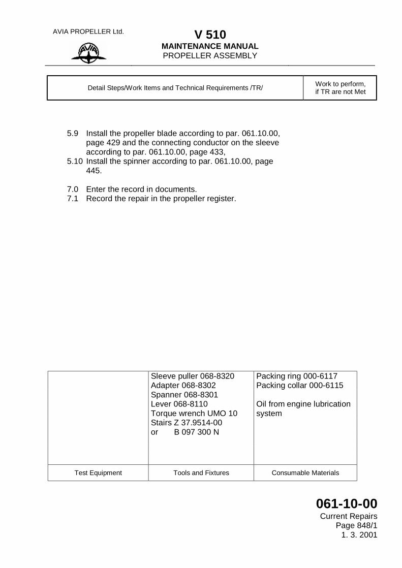
5.9 Install the propeller blade according to par. 061.10.00,
page 429 and the connecting conductor on the sleeve according to par. 061.10.00, page 433,
5.10 Install the spinner according to par. 061.10.00, page 445.
7.0 Enter the record in documents. 7.1 Record the repair in the propeller register.
Sleeve puller 068-8320 Packing ring 000-6117 Adapter 068-8302 Packing collar 000-6115 Spanner 068-8301 Lever 068-8110 Oil from engine lubrication Torque wrench UMO 10 system Stairs Z 37.9514-00 or B 097 300 N
Test Equipment Tools and Fixtures Consumable Materials
AVIA PROPELLER Ltd. V 510
MAINTENANCE MANUAL PROPELLER ASSEMBLY
061-10-00 Current Repairs Page 848/2 1. 3. 2001
(This page is intentionally left blank.)
AVIA PROPELLER Ltd. V 510
MAINTENANCE MANUAL PROPELLER ASSEMBLY
061-10-00 Storage Instructions
Page Block 900 - i 15. 11. 1999
STORAGE INSTRUCTIONS The following page block provides information needed for recommended storage and also the information needed for preservation for an appointed period.

AVIA PROPELLER Ltd. V 510
MAINTENANCE MANUAL PROPELLER ASSEMBLY
061-10-00 Storage Instructions Page Block 900 – ii 15. 11. 1999
(This page is intentionally left blank)
AVIA PROPELLER Ltd. V 510
MAINTENANCE MANUAL PROPELLER CONTROL
061-20-00 Contents
Page 1 15. 11. 1999
CONTENTS
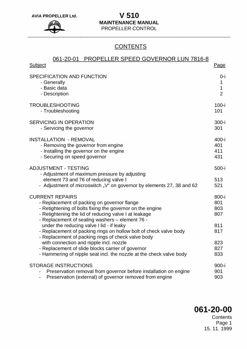
061-20-01 PROPELLER SPEED GOVERNOR LUN 7816-8 Subject Page SPECIFICATION AND FUNCTION - Generally - Basic data - Description TROUBLESHOOTING - Troubleshooting SERVICING IN OPERATION - Servicing the governor INSTALLATION - REMOVAL - Removing the governor from engine - Installing the governor on the engine - Securing on speed governor ADJUSTMENT - TESTING
- Adjustment of maximum pressure by adjusting element 73 and 76 of reducing valve I
- Adjustment of microswitch „V“ on governor by elements 27, 38 and 62 CURRENT REPAIRS - Replacement of packing on governor flange - Retightening of bolts fixing the governor on the engine - Retightening the lid of reducing valve I at leakage - Replacement of sealing washers – element 76 - under the reducing valve I lid - if leaky - Replacement of packing rings on hollow bolt of check valve body - Replacement of packing rings of check valve body with connection and nipple incl. nozzle - Replacement of slide blocks carrier of governor - Hammering of nipple seat incl. the nozzle at the check valve body STORAGE INSTRUCTIONS
- Preservation removal from governor before installation on engine - Preservation (external) of governor removed from engine
0-i 1 1 2 100-i 101 300-i 301 400-i 401 411 431 500-i 513 521 800-i 801 803 807 811 817 823 827 833 900-i 901 903
AVIA PROPELLER Ltd. V 510
MAINTENANCE MANUAL PROPELLER CONTROL
061-20-00 Contents Page 2 30. 07. 1988
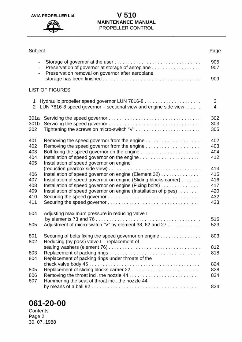
Subject Page
- Storage of governor at the user . . . . . . . . . . . . . . . . . . . . . . . . . . . . . . . . - Preservation of governor at storage of aeroplane . . . . . . . . . . . . . . . . . . - Preservation removal on governor after aeroplane
storage has been finished . . . . . . . . . . . . . . . . . . . . . . . . . . . . . . . . . . . . LIST OF FIGURES 1 Hydraulic propeller speed governor LUN 7816-8 . . . . . . . . . . . . . . . . . . . . . 2 LUN 7816-8 speed governor – sectional view and engine side view . . . . . . 301a Servicing the speed governor . . . . . . . . . . . . . . . . . . . . . . . . . . . . . . . . . . 301b Servicing the speed governor . . . . . . . . . . . . . . . . . . . . . . . . . . . . . . . . . . 302 Tightening the screws on micro-switch “V” . . . . . . . . . . . . . . . . . . . . . . . . 401 Removing the speed governor from the engine . . . . . . . . . . . . . . . . . . . . 402 Removing the speed governor from the engine . . . . . . . . . . . . . . . . . . . . 403 Bolt fixing the speed governor on the engine . . . . . . . . . . . . . . . . . . . . . . 404 Installation of speed governor on the engine . . . . . . . . . . . . . . . . . . . . . . 405 Installation of speed governor on engine (reduction gearbox side view) . . . . . . . . . . . . . . . . . . . . . . . . . . . . . . . . . . 406 Installation of speed governor on engine (Element 32) . . . . . . . . . . . . . . 407 Installation of speed governor on engine (Sliding blocks carrier) . . . . . . . 408 Installation of speed governor on engine (Fixing bolts) . . . . . . . . . . . . . . 409 Installation of speed governor on engine (Installation of pipes) . . . . . . . . 410 Securing the speed governor . . . . . . . . . . . . . . . . . . . . . . . . . . . . . . . . . . 411 Securing the speed governor . . . . . . . . . . . . . . . . . . . . . . . . . . . . . . . . . . 504 Adjusting maximum pressure in reducing valve I by elements 73 and 76 . . . . . . . . . . . . . . . . . . . . . . . . . . . . . . . . . . . . . . . 505 Adjustment of micro-switch “V” by element 38, 62 and 27 . . . . . . . . . . . . 801 Securing of bolts fixing the speed governor on engine . . . . . . . . . . . . . . . 802 Reducing (by pass) valve I – replacement of sealing washers (element 76) . . . . . . . . . . . . . . . . . . . . . . . . . . . . . . . . . . 803 Replacement of packing rings . . . . . . . . . . . . . . . . . . . . . . . . . . . . . . . . . . 804 Replacement of packing rings under throats of the check valve body 45 . . . . . . . . . . . . . . . . . . . . . . . . . . . . . . . . . . . . . . . . . 805 Replacement of sliding blocks carrier 22 . . . . . . . . . . . . . . . . . . . . . . . . . 806 Removing the throat incl. the nozzle 44 . . . . . . . . . . . . . . . . . . . . . . . . . . 807 Hammering the seat of throat incl. the nozzle 44 by means of a ball 92 . . . . . . . . . . . . . . . . . . . . . . . . . . . . . . . . . . . . . . . .
905 907
909
3 4
302 303 305
402 403 404 412
413 415 416 417 420 432 433
515 523
803
812 818
824 828 834
834
AVIA PROPELLER Ltd. V 510
MAINTENANCE MANUAL PROPELLER CONTROL
061-20-00 Contents
Page 3 15. 11. 1999
CONTENTS
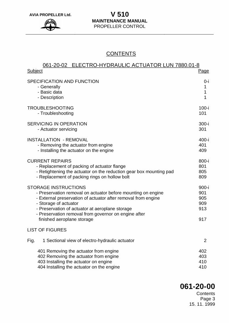
061-20-02 ELECTRO-HYDRAULIC ACTUATOR LUN 7880.01-8 Subject Page SPECIFICATION AND FUNCTION - Generally - Basic data - Description TROUBLESHOOTING - Troubleshooting SERVICING IN OPERATION - Actuator servicing INSTALLATION - REMOVAL - Removing the actuator from engine - Installing the actuator on the engine CURRENT REPAIRS - Replacement of packing of actuator flange - Retightening the actuator on the reduction gear box mounting pad - Replacement of packing rings on hollow bolt STORAGE INSTRUCTIONS
- Preservation removal on actuator before mounting on engine - External preservation of actuator after removal from engine
- Storage of actuator - Preservation of actuator at aeroplane storage
- Preservation removal from governor on engine after finished aeroplane storage
LIST OF FIGURES Fig. 1 Sectional view of electro-hydraulic actuator 401 Removing the actuator from engine 402 Removing the actuator from engine 403 Installing the actuator on engine 404 Installing the actuator on the engine
0-i 1 1 1 100-i 101 300-i 301 400-i 401 409 800-i 801 805 809 900-i 901 905 909 913 917 2 402 403 410 410
AVIA PROPELLER Ltd. V 510
MAINTENANCE MANUAL PROPELLER CONTROL
061-20-00 Contents Page 4 15. 11. 1999
(This page is intentionally left blank.)
AVIA PROPELLER Ltd. V 510
MAINTENANCE MANUAL PROPELLER SPEED GOVERNOR
LUN 7816-8
061-20-01 Specification and Function
Page Block 0 - i 15. 11. 1999
SPECIFICATION - FUNCTION The following page block provides information about overall layout, parts, basic technological data, description and operating parameters.

AVIA PROPELLER Ltd. V 510
MAINTENANCE MANUAL PROPELLER SPEED GOVERNOR
LUN 7816-8
061-20-01 Specification and Function Page Block 0 - ii 15. 11. 1999
(This page is intentionally left blank)
AVIA PROPELLER Ltd. V 510
MAINTENANCE MANUAL PROPELLER SPEED GOVERNOR
LUN 7816-8
061-20-01 Troubleshooting
Page Block 100 - i 15. 11. 1999
TROUBLESHOOTING The following page block provides information needed to perform troubleshooting of the propeller unit control system and feathering system. Using the tables provided, determine probable causes and remedies for problems encountered.
AVIA PROPELLER Ltd. V 510
MAINTENANCE MANUAL PROPELLER SPEED GOVERNOR
LUN 7816-8
061-20-01 Troubleshooting Page Block 100 - ii 15. 11. 1999
(This page is intentionally left blank)
AVIA PROPELLER Ltd. V 510
MAINTENANCE MANUAL PROPELLER SPEED GOVERNOR
LUN 7816-8
061-20-01 Servicing in Operation
Page Block 300 - i 15. 11. 1999
SERVICING IN OPERATION The following page block provides information needed when performing the works, which might occur during the operation, e.g. after installation of the propeller unit instruments, always before starting the engines and during the periodical maintenance.
AVIA PROPELLER Ltd. V 510
MAINTENANCE MANUAL PROPELLER SPEED GOVERNOR
LUN 7816-8
061-20-01 Servicing in Operation Page Block 300 - ii 15. 11. 1999
(This page is intentionally left blank)
AVIA PROPELLER Ltd. V 510
MAINTENANCE MANUAL PROPELLER SPEED GOVERNOR
LUN 7816-8
061-20-01 Installation-Removal
Page Block 400 - i 15. 11. 1999
INSTALLATION - REMOVAL The following page block provides information needed when performing the installation of the propeller on the engine or of components of the former and removal of the propeller from the engine including the components of the former.

AVIA PROPELLER Ltd. V 510
MAINTENANCE MANUAL PROPELLER SPEED GOVERNOR
LUN 7816-8
061-20-01 Installation-Removal Page Block 400 - ii 15. 11. 1999
(This page is intentionally left blank)
AVIA PROPELLER Ltd. V 510
MAINTENANCE MANUAL PROPELLER SPEED GOVERNOR
LUN 7816-8
061-20-01 Adjustment-Testing Page Block 500 - i
15. 11. 1999
ADJUSTMENT - TESTING The following page block provides information needed when performing the basic adjustment of the adjustable elements of propeller after installation on the engine or in case of propeller replacement, when performing the installation of the new engine or when installing the other instruments of the propeller unit and during the periodical maintenance. There are further here provided the procedures for checking the parameters during the engine test and after previous interventions into the facility, including the instruction for carrying out the checking of the functional properties of the propeller unit in flight.
AVIA PROPELLER Ltd. V 510
MAINTENANCE MANUAL PROPELLER SPEED GOVERNOR
LUN 7816-8
061-20-01 Adjustment-Testing Page Block 500 – ii 15. 11. 1999
(This page is intentionally left blank)
AVIA PROPELLER Ltd. V 510
MAINTENANCE MANUAL PROPELLER SPEED GOVERNOR
LUN 7816-8
061-20-01 Adjustment-Testing
Page 521 10. 11. 2000
WORK PROCEDURE
On pages 521- 524
L 410 UVP-E MAINTENANCE SCHEDULE REFERENCE No.
For: Adjustment of micro-switch „V“ on governor by elements 27, 38 and 62
Manpower Required /Manhours/
Detail Steps/ Work Items and Technical Requirements /TR/
Work to Perform, if TR are not Met
1.0 Working site 1.1 Parking area
2.0 Preparatory work 2.1 Final out the governor certificate 2.2 Remove the engine cowl 2.3 Switch on the low voltage source in the cockpit and the
signal panel on the instrument board.
NOTE: During adjustment a second technician must watch the bulb of the beta-control on the signaling panel.
5.0 Working procedure 5.1 The adjusting element (further only “element”) 38 – bolt
on lever 39 – which controls the micro-switch “V” 24 (Fig. 505) is to be set in the following manner. The connection of electrical circuit inclusive the beta–control bulb must take place by a motion of lever “Zv” 21 in the instant when the top of pin 40 comes in the position of 0.2 to 0.4 mm under the top surface 41 of the element 27 – cam, state B. For reason of easier adjustment in operation, use the feeler gauge so that the top of pin 40 will come in the distance of 0.8 mm from the foot surface 61 of element 27 when the instant of switching on occurs. It is the same as before because
AVIA PROPELLER Ltd. V 510
MAINTENANCE MANUAL PROPELLER SPEED GOVERNOR
LUN 7816-8
061-20-01 Adjustment-Testing Page 522 10. 11. 2000
Detail Steps/Work Items and Technical Requirements /TR/
Work to perform if TR are not Met
the top surface 41 is 1.2 + 0.2 mm over the foot surface 61 of element 27 1 (+0.2) – 0.8 = 0.2 to 0.4 mm. For lever “Zv” 21 and slide blocks carrier 22 see par.
061.20.01, page 4. ATTENTION: IN POSITION WHEN THE PIN 40 IS GLIDING
ON THE TOP SURFACE 41, MAKE A FOLLOWING TEST. CHECK SLIGHTLY, BY FINGER, IF IT IS YET POSSIBLE TO PUSH FURTHER THE PRESS BUTTON OF THE MICRO-SWITCH “V” 24 USING LEVER 39 WITH ELEMENT 38 . THE MOTION IS IN DIRECTION OF THE ARROW AND THE MECHANICAL STOP MUST BE REACHED. IN OPPOSITE CASE, THE MICRO-SWITCH WOULD BE DAMAGED. SECURE ELEMENT 38 BY A NUT.
NOTE. The switching on or switching off of the electrical circuit
by the micro-switch “V” is to be tested either using lever “Zv” after removing the slide blocks carrier 22 or, at best, with help of two technicians, by manual resetting of the blades. Lever AL must be in a suitable position and the slide blocks carrier 22 must be installed.
5.2 Check, when moving back in basic position – state “A”
(Fig. 505) e. g. after electrical circuit switched off, whether the top of pin 40 is in minimum sitance 0.1 mm from the foot surface 61. If this clearance is smaller adjust it by element 62 – arrest propeller. Then secure it by tightening its nut.
NOTE. The lever 39 is leaning against the screw head.
AVIA PROPELLER Ltd. V 510
MAINTENANCE MANUAL PROPELLER SPEED GOVERNOR
LUN 7816-8
061-20-01 Adjustment-Testing
Page 523 10. 11. 2000
Detail Steps/Work Items and Technical Requirements /TR/
Work to perform if TR are not Met
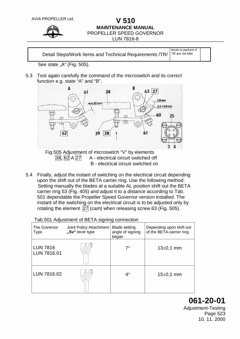
See state „A“ (Fig. 505). 5.3 Test again carefully the command of the microswitch and its correct
function e.g. state “A” and “B”.
Fig.505 Adjustment of microswitch “V” by elements
38, 62 A 27 A - electrical circuit switched off B - electrical circuit switched on
5.4 Finally, adjust the instant of switching on the electrical circuit depending
upon the shift out of the BETA carrier ring. Use the following method: Setting manually the blades at a suitable AL position shift out the BETA
carrier ring 53 (Fig. 405) and adjust it to a distance according to Tab. 501 dependable the Propeller Speed Governor version installed. The instant of the switching on the electrical circuit is to be adjusted only by rotating the element 27 (cam) when releasing screw 63 (Fig. 505).
Tab.501 Adjustment of BETA signing connection
The Governor Type
Joint Policy Attachment „Sv“ lever type
Blade setting angle of signing began
Depending upon shift out of the BETA-carrier ring
LUN 7816 LUN 7816.01
7°
13±0,1 mm
LUN 7816.02
4°
15±0,1 mm
AVIA PROPELLER Ltd. V 510
MAINTENANCE MANUAL PROPELLER SPEED GOVERNOR
LUN 7816-8
061-20-01 Adjustment-Testing Page 524 10. 11. 2000
Detail Steps/Work Items and Technical Requirements /TR/
Work to perform if TR are not Met
ATTENTION: THERE ARE TWO WASHERS UNDER THE
SCREW 63 FROM WHICH ONE IS A SPRING WASHER. THE BLADES MUST NOT BE RESET IF HOLDING THEM ON TIPS.
5.5 After adjustment, secure element 27 again by retightening the
screw 63.
NOTE: It is also possible to test the instant of switching of the electrical circuit by microswitch „V“ when connecting a suitable low voltage source (about
4.5 V) and a lamp to pins 3, 4 of the socket 25 (Fig. 505).
5.6 Secure all screws by which the adjustment has been
performed. Use securing lacquer. 6.0 Final operations. 6.1 Install the engine cowls. 6.2 Switch off the low voltage source in the cockpit. 7.0 Record in documents. 7.0 Put down a record in the governor certificate.
Feeler gauges Double-ended wrench 5,5x7 mm
Securing lacquer
0,05 to 1,0x100 mm Screwdriver 3,5x50 C 2121/0844 Slide gauge
Test Equipment
Tools and Fixtures
Consumable Materials
AVIA PROPELLER Ltd. V 510
MAINTENANCE MANUAL PROPELLER SPEED GOVERNOR
LUN 7816-8
061-20-01 Current Repairs
Page Block 800 – i 15. 11. 1999
CURRENT REPAIRS The following page block provides information concerning the performing of the common activities in course of operation, e. g. replacement of the replaceable elements, retightening the sealing elements, renewal of function or repair of minor damage.

AVIA PROPELLER Ltd. V 510
MAINTENANCE MANUAL PROPELLER SPEED GOVERNOR
LUN 7816-8
061-20-01 Current Repairs Page Block 800 – ii 15. 11. 1999
(This page is intentionally left blank)
AVIA PROPELLER Ltd. V 510
MAINTENANCE MANUAL PROPELLER SPEED GOVERNOR
LUN 7816-8
061-20-01 Storage Instructions
Page Block 900 - i 15. 11. 1999
STORAGE INSTRUCTIONS The following page block provides information needed for recommended storage and also the information needed for preservation for an appointed period.
AVIA PROPELLER Ltd. V 510
MAINTENANCE MANUAL PROPELLER SPEED GOVERNOR
LUN 7816-8
061-20-01 Storage Instructions Page Block 900 – ii 15. 11. 1999
This page is intentionally left blank)
AVIA PROPELLER Ltd. V 510
MAINTENANCE MANUAL LUN 7880.01-8
ELECTRO-HYDRAULIC ACTUATOR
061-20-02 Specification and Function
Page Block 0 - i 15. 11. 1999
SPECIFICATION - FUNCTION The following page block provides information about overall layout, parts, basic technological data, description and operating parameters.

AVIA PROPELLER Ltd. V 510
MAINTENANCE MANUAL LUN 7880.01-8
ELECTRO-HYDRAULIC ACTUATOR
061-20-02 Specification and Function Page Block 0 - ii 15. 11. 1999
(This page is intentionally left blank)

AVIA PROPELLER Ltd. V 510
MAINTENANCE MANUAL LUN 7880.01-8
ELECTRO-HYDRAULIC ACTUATOR
061-20-02 Troubleshooting
Page Block 100 - i 15. 11. 1999
TROUBLESHOOTING The following page block provides information needed to perform troubleshooting of the propeller unit control system and feathering system. Using the tables provided, determine probable causes and remedies for problems encountered.
AVIA PROPELLER Ltd. V 510
MAINTENANCE MANUAL LUN 7880.01-8
ELECTRO-HYDRAULIC ACTUATOR
061-20-02 Troubleshooting Page Block 100 – ii 15. 11. 1999
(This page is intentionally left blank)
AVIA PROPELLER Ltd. V 510
MAINTENANCE MANUAL LUN 7880.01-8
ELECTRO-HYDRAULIC ACTUATOR
061-20-02 Servicing in Operation
Page Block 300 - i 15. 11. 1999
SERVICING IN OPERATION The following page block provides information needed when performing the works, which might occur during the operation, e.g. after installation of the propeller unit instruments, always before starting the engines and during the periodical maintenance.

AVIA PROPELLER Ltd. V 510
MAINTENANCE MANUAL LUN 7880.01-8
ELECTRO-HYDRAULIC ACTUATOR
061-20-02 Servicing in Operation Page Block 300 – ii 15. 11. 1999
(This page is intentionally left blank)
AVIA PROPELLER Ltd. V 510
MAINTENANCE MANUAL LUN 7880.01-8
ELECTRO-HYDRAULIC ACTUATOR
061-20-02 Installation-Removal
Page Block 400 - i 15. 11. 1999
INSTALLATION - REMOVAL The following page block provides information needed when performing the installation of the propeller on the engine or of components of the former and removal of the propeller from the engine including the components of the former.

AVIA PROPELLER Ltd. V 510
MAINTENANCE MANUAL LUN 7880.01-8
ELECTRO-HYDRAULIC ACTUATOR
061-20-02 Installation-Removal Page Block 400 – ii 15. 11. 1999
(This page is intentionally left blank)

AVIA PROPELLER Ltd. V 510
MAINTENANCE MANUAL LUN 7880.01-8
ELECTRO-HYDRAULIC ACTUATOR
061-20-02 Current Repairs
Page Block 800 – i 15. 11. 1999
CURRENT REPAIRS The following page block provides information concerning the performing of the common activities in course of operation, e. g. replacement of the replaceable elements, retightening the sealing elements, renewal of function or repair of minor damage.

AVIA PROPELLER Ltd. V 510
MAINTENANCE MANUAL LUN 7880.01-8
ELECTRO-HYDRAULIC ACTUATOR
061-20-02 Current Repairs Page Block 800 – ii 15. 11. 1999
(This page is intentionally left blank)
AVIA PROPELLER Ltd. V 510
MAINTENANCE MANUAL LUN 7880.01-8
ELECTRO-HYDRAULIC ACTUATOR
061-20-02 Storage Instructions
Page Block 900 – i 15. 11. 1999
STORAGE INSTRUCTIONS The following page block provides information needed for recommended storage and also the information needed for preservation for an appointed period.

AVIA PROPELLER Ltd. V 510
MAINTENANCE MANUAL LUN 7880.01-8
ELECTRO-HYDRAULIC ACTUATOR
061-20-02 Storage Instructions Page Block 900 – ii 15. 11. 1999
This page is intentionally left blank)