Embed Size (px)
Citation preview

tmArduino -Compatible Prototyping & Breadboard ShieldDesign and build your own interface for your Arduino-compatible microcontroller!
SB Protoshield v1.0SB Protoshield v1.0SB Protoshield v1.0
www.solarbotics.com1-866-276-2687
Document Revision: March 12th, 2010SKU: 16090 http://www.solarbotics.com/products/16090/
Build Time: 30minsSkill Level: Beginner (2/5)
The ProtoShield features:!
! Easy access to 4 switches! Two Servo headers with selectable power feed! Convenient +5 / Gnd rails down middle of protospace! Space for170-point mini-breadboard
tm ! XBee Compatible footprint
Easy access to 4 indicator LEDs

This is an intentionally blank page.Y’know, for notes and pretty pictures and the like.
www.solarbotics.com 2 SB-Protoshield Manual v1.1
Parts List1
1
1
1
1
1
1
1
1
1 2 x FPin6 6-position Female Header Socket Strips1 2 x FPin8 8-position Female Header Socket StripsNote: You will need your own Freeduino-SB or Arduino
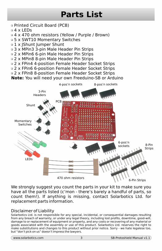
Printed Circuit Board (PCB) 4 x LEDs 4 x 470 ohm resistors (Yellow / Purple / Brown) 5 x SWT10 Momentary Switches 1 x JShunt Jumper Shunt 3 x MPin3 3-pin Male Header Pin Strips 2 x MPin6 6-pin Male Header Pin Strips 2 x MPin8 8-pin Male Header Pin Strips 2 x FPin4 4-position Female Header Socket Strips
PCB
8-pos’n sockets4-pos’n sockets
3-PinHeaders
MomentarySwitches
Shunt
LEDs
470 ohm resistors
6-pos’nsockets 8-Pin
Strips
6-Pin Strips
We strongly suggest you count the parts in your kit to make sure you have all the parts listed (c’mon - there’s barely a handful of parts, so count them!). If anything is missing, contact Solarbotics Ltd. for replacement parts information.
Disclaimer of LiabilitySolarbotics Ltd. is not responsible for any special, incidental, or consequential damages resulting from any breach of warranty, or under any legal theory, including lost profits, downtime, good-will, damage to or replacement of equipment or property, and any costs or recovering of any material or goods associated with the assembly or use of this product. Solarbotics Ltd. reserves the right to make substitutions and changes to this product without prior notice. Sorry - we hate legalese too, but “don’t pick on us” doesn’t impress the lawyers.
www.solarbotics.com 3 SB-Protoshield Manual v1.1

Construction!You’ve got a project to build, so let’s get to it!
Step 1 - 3-Pin Headers: Two of these are connected to the D9 & D10 hardware “PWM” lines on the Arduino for precise servo control. The last one lets you select between using regulated voltage or input voltage for driving your servos. Select one with the jumper shunt (see pin labels on PCB).
Step 2: The SWT1-4input switchesand Arduino reset
Step 2 - Momentary Switches: Four of these are connected to between ground and the 4-position header marked “SW” (1 to 4). These make great selector input switches to your Arduino inputs. The last is connected to the Arduino reset line.
Step 1: 3-Pin headersfor servos andservo powerselection
Select yourServo Voltage!
Step 3 - FPin4 Switch & LED Headers:The two sets of female pin header socketslet you easily wire the switches and LEDs toparts of your circuit.
Step 3: Install the twoFPin4 headers
www.solarbotics.com 4 SB-Protoshield Manual v1.1
Construction!
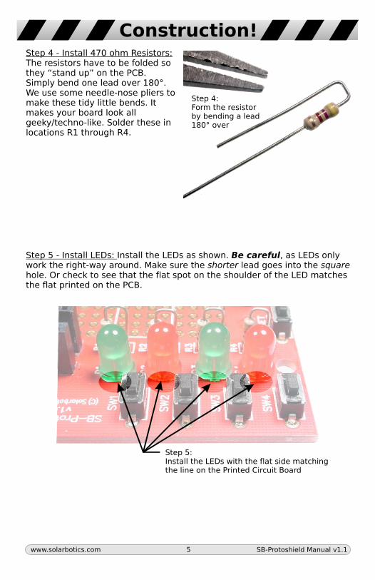
Step 4: Form the resistorby bending a lead180° over
Step 5 - Install LEDs: Install the LEDs as shown. Be careful, as LEDs only work the right-way around. Make sure the shorter lead goes into the square hole. Or check to see that the flat spot on the shoulder of the LED matches the flat printed on the PCB.
Step 4 - Install 470 ohm Resistors: The resistors have to be folded so they “stand up” on the PCB. Simply bend one lead over 180°. We use some needle-nose pliers to make these tidy little bends. It makes your board look all geeky/techno-like. Solder these in locations R1 through R4.
Step 5: Install the LEDs with the flat side matchingthe line on the Printed Circuit Board
www.solarbotics.com 5 SB-Protoshield Manual v1.1
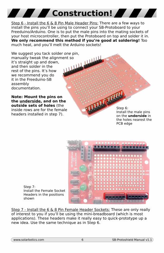
Construction!Step 6 - Install the 6 & 8 Pin Male Header Pins: There are a few ways to install the pins you’ll be using to connect your SB-Protoboard to your Freeduino/Arduino. One is to put the male pins into the mating sockets of your host microcontroller, then put the Protoboard on top and solder it in. We only recommend this method if you’re good at soldering! Too much heat, and you’ll melt the Arduino sockets!
We suggest you tack solder one pin, manually tweak the alignment so it’s straight up and down, and then solder in the rest of the pins. It’s how we recommend you do it in the Freeduino-SB assembly documentation.
Note: Mount the pins on the underside, and on the outside sets of holes (the inside rows are for the female headers installed in step 7).
Step 7 - Install the 6 & 8 Pin Female Header Sockets: These are only really of interest to you if you’ll be using the mini-breadboard (which is most applications). These headers make it really easy to quick-prototype up a new idea. Use the same technique as in Step 6.
Step 7: Install the Female SocketHeaders in the positionsshown
Step 6: Install the male pinson the underside in the holes nearest thePCB edge
www.solarbotics.com 6 SB-Protoshield Manual v1.1
Features
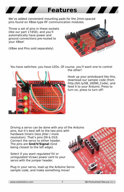
We’ve added convenient mounting pads for the 2mm-spaced pins found on XBee-type RF communication modules.
Throw a set of pins in these sockets (like our part 17450), and you’ll automatically have power and ground connections pre-routed to your XBee!
(XBee and Pins sold separately)
You have switches; you have LEDs. Of course, you’ll want one to control the other!
Hook up your protoboard like this, download our sample code (from http://bit.ly/SB_16090_Code), and feed it to your Arduino. Press to turn on, press to turn off!
Driving a servo can be done with any of the Arduinopins, but it’s best left to the two pins with hardware timers (less jitter / more resolution). That’s pins D9 & D10. Connect the servo to either header. The pins are Gnd/V/Signal (Gnd being closest to the left edge).
Select if you want regulated 5V or unregulated V(raw) power sent to your servo with the jumper header.
Plug in your servo, load up the Arduino Servo sample code, and make something move!
www.solarbotics.com 7 SB-Protoshield Manual v1.1
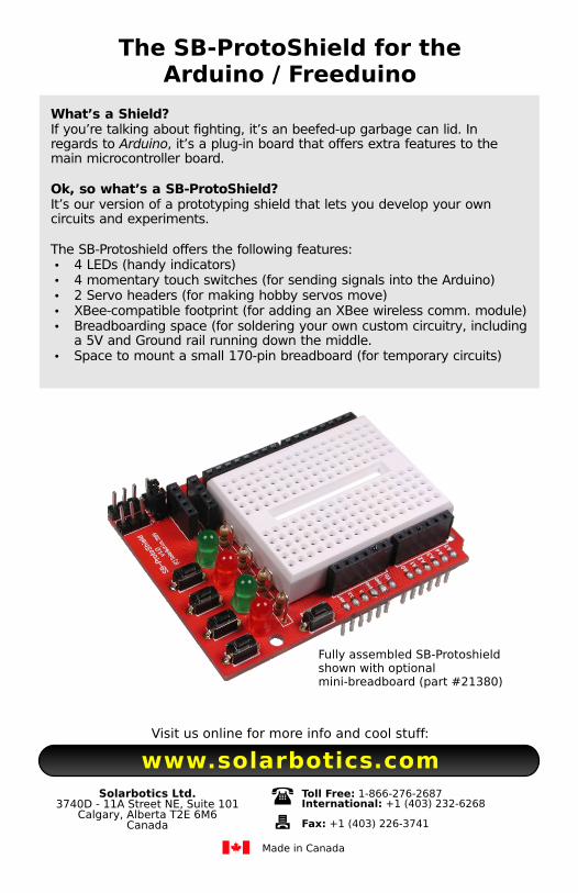
The SB-ProtoShield for the Arduino / Freeduino
What’s a Shield?If you’re talking about fighting, it’s an beefed-up garbage can lid. In regards to Arduino, it’s a plug-in board that offers extra features to the main microcontroller board.
Ok, so what’s a SB-ProtoShield?It’s our version of a prototyping shield that lets you develop your own circuits and experiments.
The SB-Protoshield offers the following features:�4 LEDs (handy indicators)�4 momentary touch switches (for sending signals into the Arduino)�2 Servo headers (for making hobby servos move)�XBee-compatible footprint (for adding an XBee wireless comm. module)�Breadboarding space (for soldering your own custom circuitry, including
a 5V and Ground rail running down the middle.�Space to mount a small 170-pin breadboard (for temporary circuits)
Fully assembled SB-Protoshieldshown with optionalmini-breadboard (part #21380)
Solarbotics Ltd.
Calgary, Alberta T2E 6M6Canada
3740D - 11A Street NE, Suite 101Toll Free: 1-866-276-2687International: +1 (403) 232-6268
Fax: +1 (403) 226-3741
Made in Canada
Visit us online for more info and cool stuff:
www.solarbotics.com