Embed Size (px)
Citation preview
- 67 -All Data Subject To Change Without Notice www.andersonpower.com
SB® 50 Connectors- up to 120 amps
| SB50® ORDERING INFORMATION |
Based off the design pioneered by Anderson in 1953, the two pole SB® connectors set the standard for DC power distribution and battery connections. SB®50 connectors feature a one piece plastic housing using stainless steel springs to hold low resistance contacts in place. Wires sizes from #16 (1.5 mm²) to #6 (13.3 mm²) are held in the smallest of the SB® series housings.
• Low Resistance Silver or Tin Plated Copper Contacts Allows UL rated currents up to 120 amps
• UL Rated for Hot Plugging up to 50 Amps Great for battery or other applications where the ability to interrupt circuits is required
• Wire, PCB, and Busbar Contacts Allows one connection system to meet multiple needs
SB®50 Standard HousingsThe smallest SB® housings work with wire contacts up to 6 AWG [10 mm²] as well as PCB, and busbar contacts. Genderless design mates with itself. Mechanical keys are color coded. Description ---- Part Numbers ----Minimum Quantity .... 500 100 ...Yellow 992G5-BK 992G5Orange 992G7-BK 992G7Red 992G1-BK 992G1Gray 992-BK 992Blue 992G4-BK 992G4Green 992G6-BK 992G6Black 992G2-BK 992G2NOTE: SB®50 Black and Gray housings have the same keying features and can be intermated.
SB®50 Chemical Resistant HousingsSame features as the Standard SB®50 but molded in a chemical resistant PBT/ PC blend. Suitable for use to -40°C. Description ---- Part Numbers ----Minimum Quantity .... 500 100 ...Red P992G1-BK P992G1Gray P992-BK P992Black P992G2-BK P992G2NOTE: SB®50 Black and Gray housings have the same keying features and can be intermated.
SECTIO
N 3
SB® 50
[ 81.3 ]3.20
[ 3.7 ]Ø 0.14
(2) PLC’S
[ 15.9 ]0.63
Material ID[ 35.1 ]1.38
[ 22.5 ]0.89
[ 19.1 ]0.75
[ 6.4 ]0.25
Bottom View
MatedLength
P = Chemical Resistant
©2018AndersonPowerProducts,Inc.Allrightsreserved.APP®,AndersonPowerProducts®,A®,SB®andtheAPPLogoareregisteredtrademarksofAndersonPowerProducts,Inc.
- 68 - All Data Subject To Change Without Noticewww.andersonpower.com
[ 69.1 ]2.72
[ 2.0 ]0.08
[ 17.1 ]0.68
See Busbar contact drawing on website for further detail.
[ 3.7 ]Ø 0.14 (2)
[ 11.4 ]0.45
[ 22.6 ]0.89
[ 19.05 ]0.750
[ 21.6 ]0.85[ 8.0 ]
0.32
[ 27.4 ]1.08
[ 35.0 ]1.380
[ 15.6 ]0.62
[ 63.6 ]2.51
[ 23.7 ]0.93 [ x ]
x
Top ViewSide View
See PCB contact drawing on website for further detail.
[ 25.4 ]1.00
[ 12.19 ]0.480
[ 1.27 ]0.050
[ 17.5 ]0.69[ 6.10 ]
0.240
[ 2.42 ]0.095
[ 24.6 ]0.97
[ 8.1 ]0.32
[ 7.6 ]0.30
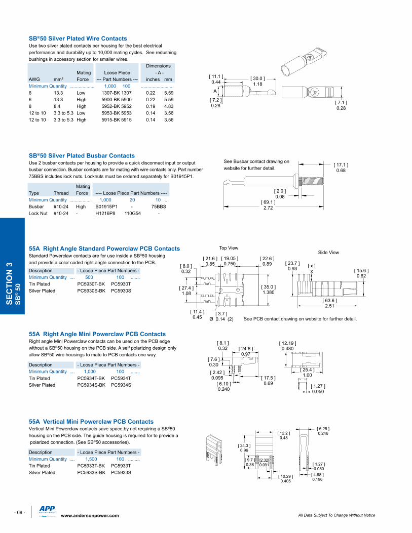
SB®50 Silver Plated Wire ContactsUse two silver plated contacts per housing for the best electrical performance and durability up to 10,000 mating cycles. See redushing bushings in accessory section for smaller wires. Dimensions Mating LoosePiece -A-AWG mm² Force --- Part Numbers --- inches mmMinimum Quantity ................... 1,000 100 ......................... 6 13.3 Low 1307-BK1307 0.22 5.596 13.3 High 5900-BK 5900 0.22 5.598 8.4 High 5952-BK 5952 0.19 4.8312to10 3.3to5.3 Low 5953-BK5953 0.14 3.5612 to 10 3.3 to 5.3 High 5915-BK 5915 0.14 3.56
SB®50 Silver Plated Busbar ContactsUse 2 busbar contacts per housing to provide a quick disconnect input or output busbar connection. Busbar contacts are for mating with wire contacts only. Part number 75BBSincludeslocknuts.Locknutsmustbeorderedseparately for B01915P1.
Mating Type Thread Force ----LoosePiecePartNumbers----Minimum Quantity ................. 1,000 20 10 ...Busbar #10-24 High B01915P1 - 75BBSLockNut #10-24 - H1216P8 110G54 -
55A Right Angle Standard Powerclaw PCB ContactsStandard Powerclaw contacts are for use inside a SB®50 housing and provide a color coded right angle connection to the PCB.
Description - LoosePiecePartNumbers-Minimum Quantity .... 500 100 .......Tin Plated PC5930T-BK PC5930TSilver Plated PC5930S-BK PC5930S
55A Right Angle Mini Powerclaw PCB ContactsRight angle Mini Powerclaw contacts can be used on the PCB edge without a SB®50 housing on the PCB side. A self polarizing design only allow SB®50 wire housings to mate to PCB contacts one way.
Description - LoosePiecePartNumbers-Minimum Quantity .... 1,000 100 .......Tin Plated PC5934T-BK PC5934TSilver Plated PC5934S-BK PC5934S
55A Vertical Mini Powerclaw PCB Contacts Vertical Mini Powerclaw contacts save space by not requiring a SB®50 housing on the PCB side. The guide housing is required for to provide a polarized connection. (See SB®50 accessories). Description - LoosePiecePartNumbers-Minimum Quantity .... 1,500 100 .........Tin Plated PC5933T-BK PC5933TSilver Plated PC5933S-BK PC5933S
[ 30.0 ]1.18
[ 7.2 ]0.28
[ 11.1 ]0.44
[ 7.1 ]0.28
A
SEC
TIO
N 3
SB® 5
0
[ 12.2 ]0.48
[ 24.3 ]0.96
[ 9.7 ]0.38
[2.32]0.091
[ 10.29 ]0.405
[ 6.25 ]0.246
[ 1.27 ]0.050
[ 4.98 ]0.196
- 69 -All Data Subject To Change Without Notice www.andersonpower.com
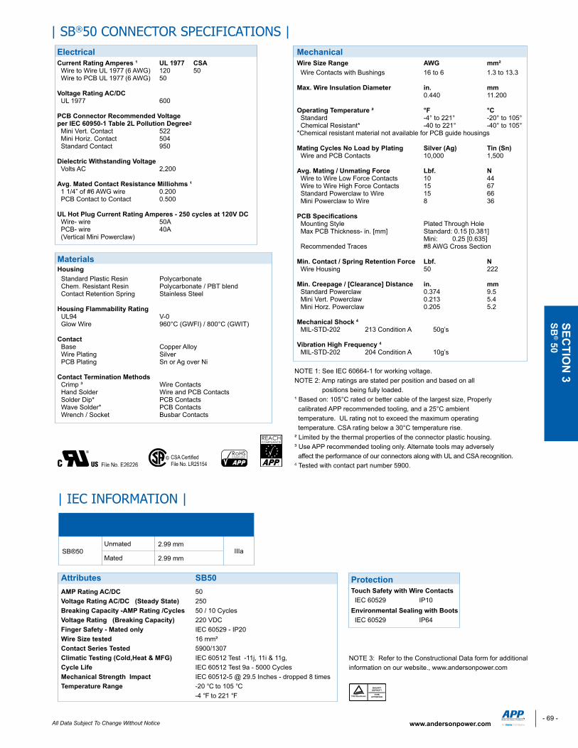
| SB®50 CONNECTOR SPECIFICATIONS |ElectricalCurrent Rating Amperes ¹ UL 1977 CSAWiretoWireUL1977(6AWG) 120 50WiretoPCBUL1977(6AWG) 50 Voltage Rating AC/DCUL1977 600 PCB Connector Recommended Voltageper IEC 60950-1 Table 2L Pollution Degree2
Mini Vert. Contact 522 Mini Horiz. Contact 504 Standard Contact 950 Dielectric Withstanding Voltage Volts AC 2,200 Avg. Mated Contact Resistance Milliohms ¹ 11/4”of#6AWGwire 0.200 PCB Contact to Contact 0.500 UL Hot Plug Current Rating Amperes - 250 cycles at 120V DC Wire- wire 50A PCB- wire 40A (Vertical Mini Powerclaw)
Mechanical Wire Size Range AWG mm² Wire Contacts with Bushings 16 to 6 1.3 to 13.3 Max. Wire Insulation Diameter in. mm 0.440 11.200 Operating Temperature ² °F °C Standard -4° to 221° -20° to 105° Chemical Resistant* -40 to 221° -40° to 105°*Chemical resistant material not available for PCB guide housings Mating Cycles No Load by Plating Silver (Ag) Tin (Sn) Wire and PCB Contacts 10,000 1,500 Avg. Mating / Unmating Force Lbf. NWiretoWireLowForceContacts 10 44 Wire to Wire High Force Contacts 15 67 Standard Powerclaw to Wire 15 66 Mini Powerclaw to Wire 8 36 PCB Specifications Mounting Style Plated Through Hole Max PCB Thickness- in. [mm] Standard: 0.15 [0.381] Mini: 0.25 [0.635] Recommended Traces #8 AWG Cross Section Min. Contact / Spring Retention Force Lbf. N Wire Housing 50 222 Min. Creepage / [Clearance] Distance in. mm Standard Powerclaw 0.374 9.5 Mini Vert. Powerclaw 0.213 5.4 Mini Horz. Powerclaw 0.205 5.2
Mechanical Shock 4
MIL-STD-202 213ConditionA 50g’s
Vibration High Frequency 4
MIL-STD-202 204ConditionA 10g’s
Materials Housing Standard Plastic Resin Polycarbonate Chem. Resistant Resin Polycarbonate / PBT blend Contact Retention Spring Stainless Steel Housing Flammability Rating UL94 V-0 Glow Wire 960°C (GWFI) / 800°C (GWIT) Contact Base Copper Alloy Wire Plating Silver PCB Plating Sn or Ag over Ni Contact Termination Methods Crimp ³ Wire Contacts Hand Solder Wire and PCB Contacts Solder Dip* PCB Contacts Wave Solder* PCB Contacts Wrench / Socket Busbar Contacts
NOTE 1: See IEC 60664-1 for working voltage.NOTE 2: Amp ratings are stated per position and based on all positions being fully loaded. ¹ Based on: 105°C rated or better cable of the largest size, Properly calibrated APP recommended tooling, and a 25°C ambient temperature.ULratingnottoexceedthemaximumoperating temperature. CSA rating below a 30°C temperature rise.²Limitedbythethermalpropertiesoftheconnectorplastichousing.³ Use APP recommended tooling only. Alternate tools may adversely affecttheperformanceofourconnectorsalongwithULandCSArecognition.4 Tested with contact part number 5900.
SECTIO
N 3
SB® 50
Protection Touch Safety with Wire Contacts IEC 60529 IP10Environmental Sealing with Boots IEC 60529 IP64
Unmated
Mated
Connector Series Configurations
Creepage/Clearanceper IEC 60950-1
IIIa
MaterialGroup
SB®502.99 mm
2.99 mm
Attributes SB50AMP Rating AC/DC 50Voltage Rating AC/DC (Steady State) 250Breaking Capacity -AMP Rating /Cycles 50 / 10 CyclesVoltage Rating (Breaking Capacity) 220 VDCFinger Safety - Mated only IEC 60529 - IP20Wire Size tested 16 mm²Contact Series Tested 5900/1307Climatic Testing (Cold,Heat & MFG) IEC60512Test-11j,11i&11g,Cycle Life IEC 60512 Test 9a - 5000 CyclesMechanical Strength Impact IEC 60512-5 @ 29.5 Inches - dropped 8 timesTemperature Range -20 °C to 105 °C -4 °F to 221 °F
NOTE 3: Refer to the Constructional Data form for additional information on our website., www.andersonpower.com
| IEC INFORMATION |
- 70 - All Data Subject To Change Without Noticewww.andersonpower.com
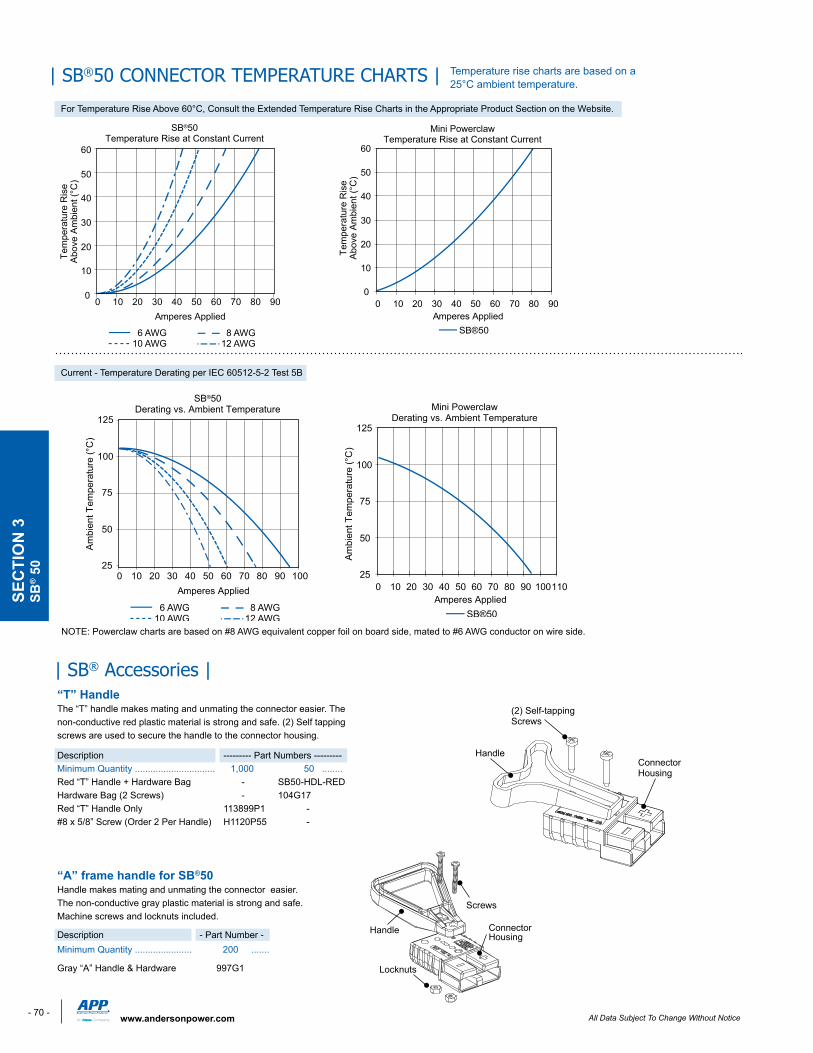
“T” Handle The“T”handlemakesmatingandunmatingtheconnectoreasier.Thenon-conductive red plastic material is strong and safe. (2) Self tapping screws are used to secure the handle to the connector housing.
Description --------- Part Numbers --------- Minimum Quantity ............................... 1,000 50 ........Red“T”Handle+HardwareBag - SB50-HDL-REDHardware Bag (2 Screws) - 104G17Red“T”HandleOnly 113899P1 -#8x5/8”Screw(Order2PerHandle) H1120P55 -
“A” frame handle for SB®50 Handle makes mating and unmating the connector easier. The non-conductive gray plastic material is strong and safe. Machine screws and locknuts included.
Description - Part Number -Minimum Quantity ...................... 200 .......
Gray“A”Handle&Hardware 997G1
| SB® Accessories |
| SB®50 CONNECTOR TEMPERATURE CHARTS |
6 AWG 8 AWG10 AWG 12 AWG
25
50
75
100
125
0 10 20 30 40 50 60 70 80 90 100
SB®50Derating vs. Ambient Temperature
Amperes Applied
Am
bien
t Tem
pera
ture
(°C
)
(2) Self-tappingScrews
HandleConnectorHousing
0
10
20
30
40
50
60
0 10 20 30 40 50 60 70 80 90
6 AWG 8 AWG10 AWG 12 AWG
SB®50Temperature Rise at Constant Current
Amperes Applied
Tem
pera
ture
Ris
eA
bove
Am
bien
t (°C
)
NOTE: Powerclaw charts are based on #8 AWG equivalent copper foil on board side, mated to #6 AWG conductor on wire side.
25
50
75
100
125
0 10 20 30 40 50 60 70 80 90 100110
Mini PowerclawDerating vs. Ambient Temperature
Amperes AppliedSB®50
Am
bien
t Tem
pera
ture
(°C
)
0
10
20
30
40
50
60
0 10 20 30 40 50 60 70 80 90
Mini PowerclawTemperature Rise at Constant Current
Amperes AppliedSB®50
Tem
pera
ture
Ris
eA
bove
Am
bien
t (°C
)
Screws
Handle ConnectorHousing
Locknuts
For Temperature Rise Above 60°C, Consult the Extended Temperature Rise Charts in the Appropriate Product Section on the Website.
Current - Temperature Derating per IEC 60512-5-2 Test 5B
Temperature rise charts are based on a 25°C ambient temperature.
SEC
TIO
N 3
SB® 5
0
- 71 -All Data Subject To Change Without Notice www.andersonpower.com
SECTIO
N 3
SB® 50
IDLength
Wire Entrance
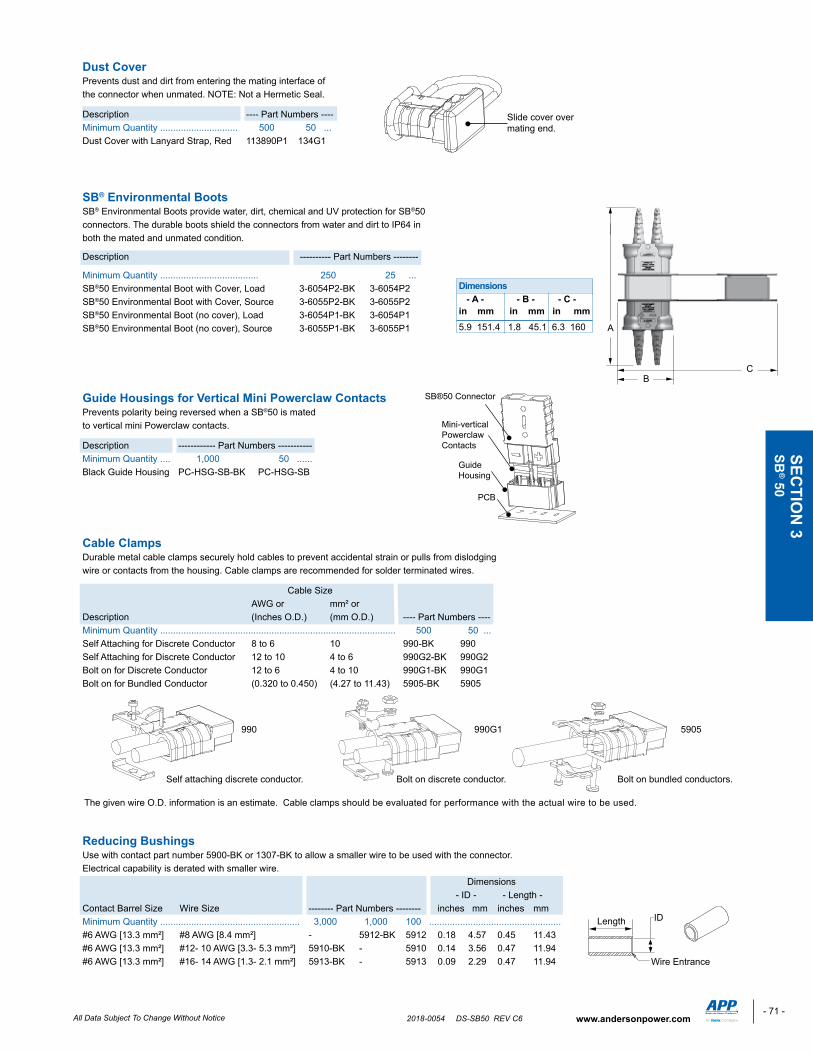
990 990G1 5905
Self attaching discrete conductor. Bolt on discrete conductor. Bolt on bundled conductors.
The given wire O.D. information is an estimate. Cable clamps should be evaluated for performance with the actual wire to be used.
PCB
SB®50 Connector
Mini-vertical Powerclaw Contacts
Guide Housing
Dimensions - A - - B - - C -in mm in mm in mm5.9 151.4 1.8 45.1 6.3 160 A
BC
Slide cover over mating end.
Dust Cover Prevents dust and dirt from entering the mating interface of the connector when unmated. NOTE: Not a Hermetic Seal.
Description ---- Part Numbers ---- Minimum Quantity .............................. 500 50 ...DustCoverwithLanyardStrap,Red 113890P1 134G1
SB® Environmental BootsSB® Environmental Boots provide water, dirt, chemical and UV protection for SB®50 connectors. The durable boots shield the connectors from water and dirt to IP64 in both the mated and unmated condition.
Description ---------- Part Numbers --------
Minimum Quantity ...................................... 250 25 ... SB®50EnvironmentalBootwithCover,Load 3-6054P2-BK 3-6054P2SB®50 Environmental Boot with Cover, Source 3-6055P2-BK 3-6055P2SB®50EnvironmentalBoot(nocover),Load 3-6054P1-BK 3-6054P1SB®50 Environmental Boot (no cover), Source 3-6055P1-BK 3-6055P1
Guide Housings for Vertical Mini Powerclaw ContactsPrevents polarity being reversed when a SB®50 is mated to vertical mini Powerclaw contacts.
Description ------------ Part Numbers ----------- Minimum Quantity .... 1,000 50 ......Black Guide Housing PC-HSG-SB-BK PC-HSG-SB
Cable ClampsDurable metal cable clamps securely hold cables to prevent accidental strain or pulls from dislodging wire or contacts from the housing. Cable clamps are recommended for solder terminated wires.
Cable Size AWG or mm² or Description (Inches O.D.) (mm O.D.) ---- Part Numbers ----Minimum Quantity ........................................................................................... 500 50 ...Self Attaching for Discrete Conductor 8 to 6 10 990-BK 990Self Attaching for Discrete Conductor 12 to 10 4 to 6 990G2-BK 990G2Bolt on for Discrete Conductor 12 to 6 4 to 10 990G1-BK 990G1Bolt on for Bundled Conductor (0.320 to 0.450) (4.27 to 11.43) 5905-BK 5905
Reducing Bushings Use with contact part number 5900-BK or 1307-BK to allow a smaller wire to be used with the connector. Electrical capability is derated with smaller wire. Dimensions -ID- -Length-Contact Barrel Size Wire Size -------- Part Numbers -------- inches mm inches mmMinimum Quantity ...................................................... 3,000 1,000 100 ...................................................#6 AWG [13.3 mm²] #8 AWG [8.4 mm²] - 5912-BK 5912 0.18 4.57 0.45 11.43#6 AWG [13.3 mm²] #12- 10 AWG [3.3- 5.3 mm²] 5910-BK - 5910 0.14 3.56 0.47 11.94#6 AWG [13.3 mm²] #16- 14 AWG [1.3- 2.1 mm²] 5913-BK - 5913 0.09 2.29 0.47 11.94
2018-0054 DS-SB50 REV C6
- 86 - All Data Subject To Change Without Noticewww.andersonpower.com
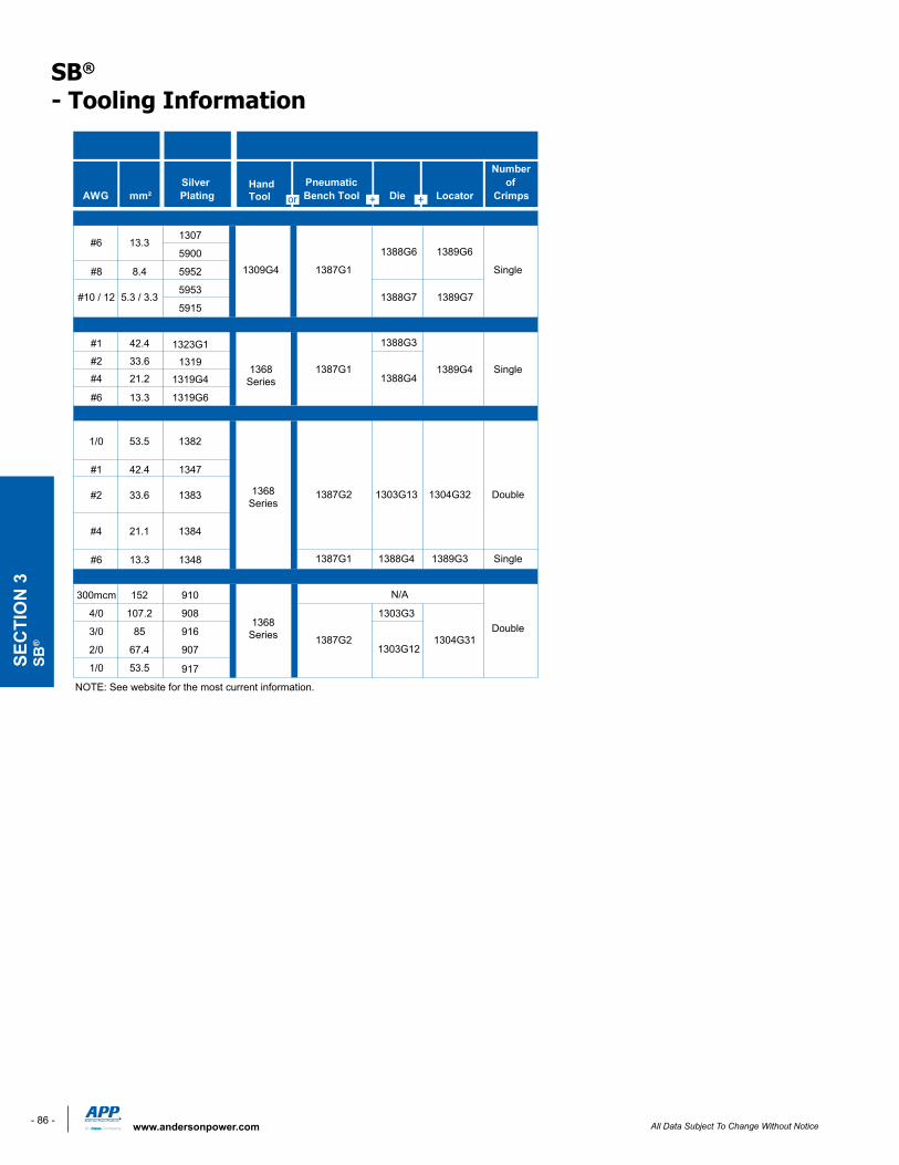
SB® - Tooling Information
1307
5900
#8 8.4 5952
5953
5915
#1 42.4 1323G1#2 33.6 1319#4 21.2 1319G4
#6 13.3 1319G6
#1 42.4 1347
1387G2 1303G13 1304G32 Double
#6 13.3 1348 1387G1 1388G4 1389G3 Single
300mcm 152 910
4/0 107.2 908 1303G3
3/0 85 916
2/0 67.4 907
1/0 53.5 917
Double
SB®50
N/A
1387G2 1304G311303G12
Single
1387G1
1388G6
SB®120
#10 / 12
Single
5.3 / 3.3 1388G7
#6 13.31389G6
1309G4
SB®175
1/0 53.5 1382
1388G3
#2 33.6 1383
1388G41389G4
SB®350
#4 21.1 1384
1387G11368Series
AWG mm²HandTool
Pneumatic Bench Tool Die Locator
Number of
Crimps
Wire Size Loose Piece Contact Crimp ToolsLoose Piece
Part Numbers
Silver Plating
NOTE: See website for the most current information.
1368Series
1368Series
1389G7
SEC
TIO
N 3
SB®

![SB Smart Connector - up to 230 Amps · For SB® Smart Auxiliary Module 111812P16 0.099 / 0.106 2.51 / 2.69 1.125 28.58 A B Pins Sockets [ 1.03 ] 26.2 [ 1.00 ] 25.3 [ 0.88 ] 22.3 [](https://img.pdfslide.us/doc/110x75/5f6215c9fad79e1dea5fa4e1/sb-smart-connector-up-to-230-amps-for-sb-smart-auxiliary-module-111812p16-0099.jpg)
![SB 175 Connectors - up to 280 Amps...The second to largest SB® housings work with wire contacts up to 1/0 AWG [50 mm²] as well as busbar contacts. Genderless design mates with itself](https://img.pdfslide.us/doc/110x75/5e5fe906b84aef7019610ebd/sb-175-connectors-up-to-280-amps-the-second-to-largest-sb-housings-work.jpg)