Embed Size (px)
Citation preview
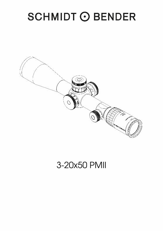
3-20x50 PMII

Operating Manual
3-20x50 PMII Rev.00
Page 2 of 23
Schmidt & Bender GmbH & Co. KG • Am Grossacker 42 • D-35444 Biebertal Tel. +49 (0) 64 09-81 15-0 • Fax +49 (0) 64 09-81 15-11 [email protected] • www.schmidt-bender.de
1.� Scope description .......................................................................................... 3�
2.� Technical data ............................................................................................... 4�
2.1� General Data ............................................................................................ 4�
2.2� Dimensions ................................................................................................. 4�
3.� Accessories / Scope of supply ..................................................................... 5�
4.� Operating instructions ................................................................................... 6�
4.2� Parallax adjustment .................................................................................. 8�
4.3� Using the illumination control .................................................................. 9�
4.4� Changing the battery ............................................................................ 10�
4.5� Using the scope covers.......................................................................... 11�
4.1� Using the sun shade................................................................................ 11�
4.2� Description of the reticles ...................................................................... 11�
5.� Correction of the point of impact............................................................... 16�
5.1� Using the MTC LT Turrets ........................................................................ 16�
5.2� Zeroing the scope ................................................................................... 17�
5.3� Elevation adjustment ............................................................................. 19�
5.4� Windage adjustment ............................................................................. 19�
6.� Maintenance ................................................................................................ 20�
6.1� Storage temperature ............................................................................. 20�
7.� Warranty certificate ..................................................................................... 21�
Operating Manual
3-20x50 PMII Rev.00
Page 3 of 23
Schmidt & Bender GmbH & Co. KG • Am Grossacker 42 • D-35444 Biebertal Tel. +49 (0) 64 09-81 15-0 • Fax +49 (0) 64 09-81 15-11 [email protected] • www.schmidt-bender.de
1. Scope description
1.1 Introduction The Schmidt & Bender PM II series scopes are designed to meet the unique challenges of high precision shooting. Their quality and function make it possible to achieve exceptional shooting results as well as to fulfill the critical and demanding needs of official, law enforcement and tactical applications. Strict observation of the following operating instructions is prerequisite for successful long-term use.
1.2 Safety instructions Never look into the sun or into laser light with the scope. This may cause serious eye injuries. Do not tamper with the scope. Any repairs beyond the maintenance described in the maintenance manual should only be performed by Schmidt & Bender or by other specialists authorized by Schmidt & Bender. Protect the scope against shocks beyond normal use. Avoid unnecessary long exposure of the scope to direct sunlight; intense and excessive sun radiation will cause extremely high temperatures inside the tube which may be detrimental to the scope. The firearm and the scope must be properly mounted by a qualified specialist. Perfect mounting is an essential requirement for maximum accuracy and efficient functioning of the firearm and the scope. Be sure to assume the proper firing position and keep a correct eye relief in order to obtain an optimal full field of view and to avoid any injuries due to the recoil of the weapon.
Operating Manual
3-20x50 PMII
Schmidt & Bender GmbH & Co. KG • Am Grossacker 42 • D-35444 BiebertalTel. +49 (0) 64 09-81 15-0 • Fax +49 (0) 64 09-81 [email protected] • www.schmidt-bender.de
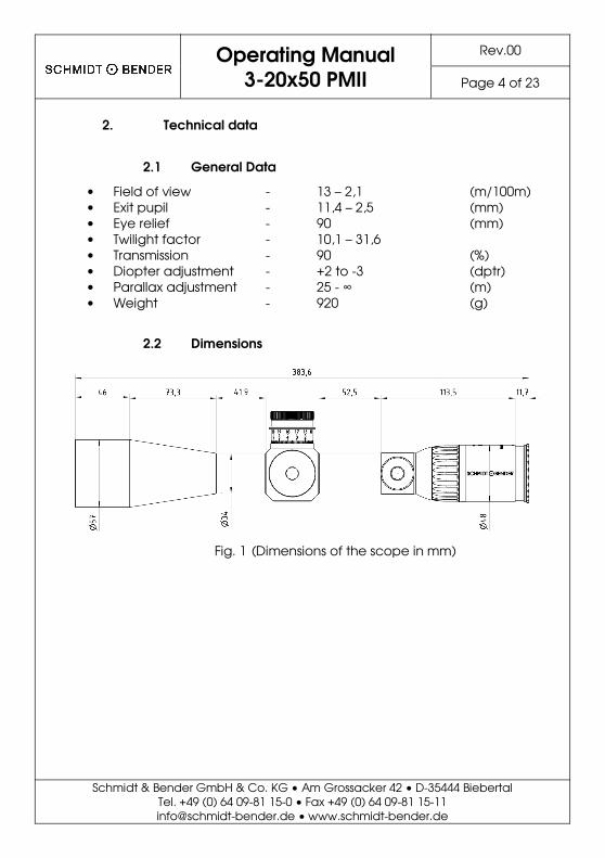
2. Technical data
2.1 General Data
• Field of view - 13 – 2,1 • Exit pupil - 11,4 – 2,5 • Eye relief - 90 • Twilight factor - 10,1 – 31,6 • Transmission - 90 • Diopter adjustment - +2 to -3 • Parallax adjustment - 25 - � • Weight - 920
2.2 Dimensions
Fig. 1 (Dimensions of the scope in mm)
Rev.00
Page 4 of 23
35444 Biebertal 11
bender.de
(m/100m) (mm) (mm)
(%) (dptr) (m) (g)
(Dimensions of the scope in mm)
Operating Manual
3-20x50 PMII Rev.00
Page 5 of 23
Schmidt & Bender GmbH & Co. KG • Am Grossacker 42 • D-35444 Biebertal Tel. +49 (0) 64 09-81 15-0 • Fax +49 (0) 64 09-81 15-11 [email protected] • www.schmidt-bender.de
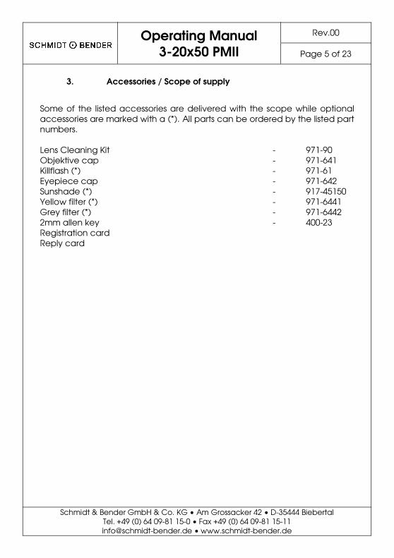
3. Accessories / Scope of supply
Some of the listed accessories are delivered with the scope while optional accessories are marked with a (*). All parts can be ordered by the listed part numbers. Lens Cleaning Kit - 971-90 Objektive cap - 971-641 Killflash (*) - 971-61 Eyepiece cap - 971-642 Sunshade (*) - 917-45150 Yellow filter (*) - 971-6441 Grey filter (*) - 971-6442 2mm allen key - 400-23 Registration card Reply card
Operating Manual
3-20x50 PMII
Schmidt & Bender GmbH & Co. KG • Am Grossacker 42 • D-35444 BiebertalTel. +49 (0) 64 09-81 15-0 • Fax +49 (0) 64 09-81 [email protected] • www.schmidt-bender.de
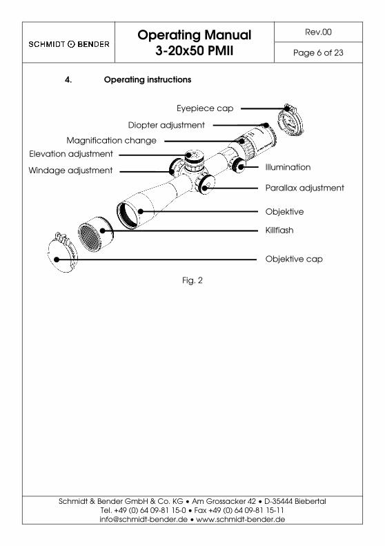
4. Operating instructions
Fig. 2
Eyepiece cap
Illumination
Parallax adjustment
Objektive
Killflash
Objektive cap
Diopter adjustment
Magnification change
Windage adjustment
Elevation adjustment
Rev.00
Page 6 of 23
35444 Biebertal 11
bender.de
Illumination
Parallax adjustment
Objektive
Killflash
Objektive cap
Operating Manual
3-20x50 PMII
Schmidt & Bender GmbH & Co. KG • Am Grossacker 42 • D-35444 BiebertalTel. +49 (0) 64 09-81 15-0 • Fax +49 (0) 64 09-81 [email protected] • www.schmidt-bender.de
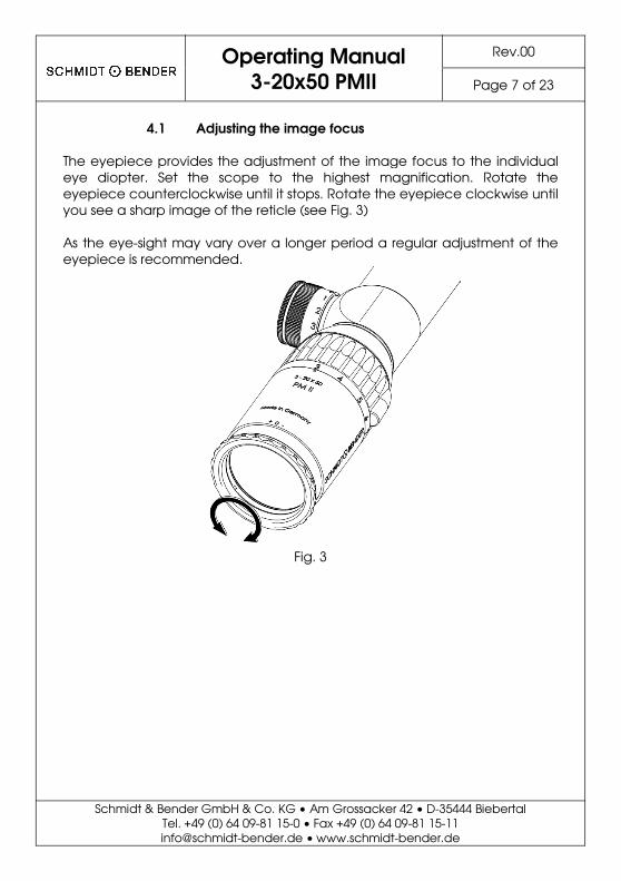
4.1 Adjusting the image focus
The eyepiece provides the adjustment of the image focus to the individual eye diopter. Set the scope to the highest magnification. Rotate the eyepiece counterclockwise until it stops. Rotate the eyepiece clockwise until you see a sharp image of the reticle (see Fig. 3) As the eye-sight may vary over a longer period a regular adjustmeneyepiece is recommended.
Fig. 3
Rev.00
Page 7 of 23
35444 Biebertal 11
bender.de
The eyepiece provides the adjustment of the image focus to the individual . Set the scope to the highest magnification. Rotate the
eyepiece counterclockwise until it stops. Rotate the eyepiece clockwise until
sight may vary over a longer period a regular adjustment of the
Operating Manual
3-20x50 PMII
Schmidt & Bender GmbH & Co. KG • Am Grossacker 42 • D-35444 BiebertalTel. +49 (0) 64 09-81 15-0 • Fax +49 (0) 64 09-81 [email protected] • www.schmidt-bender.de
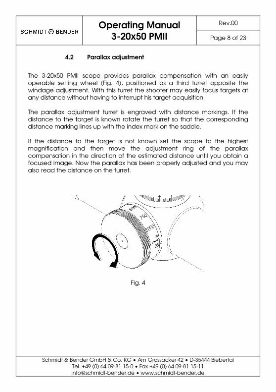
4.2 Parallax adjustment
The 3-20x50 PMII scope provides parallax compensation with an operable setting wheel (Fig. 4), positioned as a third turret opposite the windage adjustment. With this turret the shooter may easily focus targets at any distance without having to interrupt his target acquisition. The parallax adjustment turret is engraved with distance markings. If the distance to the target is known rotate the turret so that the corresponding distance marking lines up with the index mark on the saddle. If the distance to the target is not known set the scope to the highest magnification and then move the adjustment ring of the parallax compensation in the direction of the estimated distance until you obtain a focused image. Now the parallax has been properly adjusted and you may also read the distance on the turret.
Fig. 4
Rev.00
Page 8 of 23
35444 Biebertal 11
bender.de
PMII scope provides parallax compensation with an easily ), positioned as a third turret opposite the
windage adjustment. With this turret the shooter may easily focus targets at any distance without having to interrupt his target acquisition.
parallax adjustment turret is engraved with distance markings. If the distance to the target is known rotate the turret so that the corresponding distance marking lines up with the index mark on the saddle.
the scope to the highest magnification and then move the adjustment ring of the parallax compensation in the direction of the estimated distance until you obtain a focused image. Now the parallax has been properly adjusted and you may
Operating Manual
3-20x50 PMII Rev.00
Page 9 of 23
Schmidt & Bender GmbH & Co. KG • Am Grossacker 42 • D-35444 Biebertal Tel. +49 (0) 64 09-81 15-0 • Fax +49 (0) 64 09-81 15-11 [email protected] • www.schmidt-bender.de
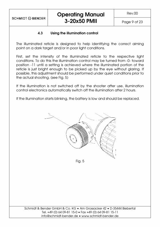
4.3 Using the illumination control
The illuminated reticle is designed to help identifying the correct aiming point on a dark target and/or in poor light conditions. First, set the intensity of the illuminated reticle to the respective light conditions. To do this the illumination control may be turned from -0- toward position -11 until a setting is achieved where the illuminated portion of the reticle is just bright enough to be picked up by the eye without glaring. If possible, this adjustment should be performed under quiet conditions prior to the actual shooting. (see Fig. 5) If the illumination is not switched off by the shooter after use, illumination control electronics automatically switch off the illumination after 2 hours. If the illumination starts blinking, the battery is low and should be replaced.
Fig. 5
Operating Manual
3-20x50 PMII
Schmidt & Bender GmbH & Co. KG • Am Grossacker 42 • D-35444 BiebertalTel. +49 (0) 64 09-81 15-0 • Fax +49 (0) 64 09-81 [email protected] • www.schmidt-bender.de
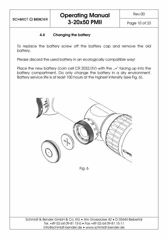
4.4 Changing the battery
To replace the battery screw off the battery cap and remove the old battery. Please discard the used battery in an ecologically compatible way! Place the new battery (coin cell CR 2032/3V) with the „+" facing up into the battery compartment. Do only change the battery in a dry environment. Battery service life is at least 100 hours at the highest intensity (se
Fig. 6
Rev.00
Page 10 of 23
35444 Biebertal 11
bender.de
To replace the battery screw off the battery cap and remove the old
Please discard the used battery in an ecologically compatible way!
the „+" facing up into the battery compartment. Do only change the battery in a dry environment. Battery service life is at least 100 hours at the highest intensity (see Fig. 6).
Operating Manual
3-20x50 PMII Rev.00
Page 11 of 23
Schmidt & Bender GmbH & Co. KG • Am Grossacker 42 • D-35444 Biebertal Tel. +49 (0) 64 09-81 15-0 • Fax +49 (0) 64 09-81 15-11 [email protected] • www.schmidt-bender.de
4.5 Using the scope covers
To protect the scope and its lenses against adverse environmental conditions like sand, dust, rain, snow, etc., the protective flip-up caps of objective and eyepiece should be closed after every use of the scope. Before shooting, make sure that the caps are open.
4.1 Using the anti-reflective device (ARD)
The ARD prevents the reflection of light sources in the objective lens which might reveal the location of the shooter. It should be taken into consideration that the ARD decreases the light output of the scope, which especially yields in a lower performance in low light conditions.
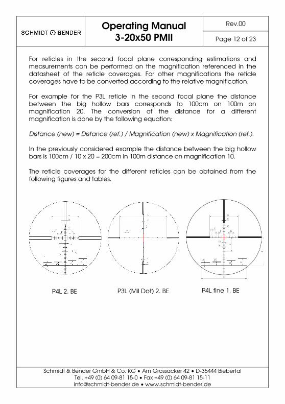
4.2 Description of the reticles
The available reticles provide various options to estimate or to measure important parameters by means of the reticle coverages. In combination with the focus (parallax adjustment) and the ballistic compensation (elevation and windage adjustment) this allows the shooter to shoot precisely on large distances. The reticle is located in the first or second focal plane. For reticles in the first focal plane the reticle coverages are constant on all magnifications. For reticles in the second focal plane the reticle coverages vary with the magnification. For example for the P3L reticle in the first focal plane the distance of the circles corresponds to 10cm in 100m distance. The shooter can thus calculate the distance to a target of known or guessed size by measuring the size of the target with the reticle. If a target of known or guessed size of 10cm fits in between two circles of the P3L reticle, the distance to the target is 100m. With the obtained distance value the parallax can be adjusted and the bullet drop can be compensated by adjusting the windage turret accordingly.
Operating Manual
3-20x50 PMII Rev.00
Page 12 of 23
Schmidt & Bender GmbH & Co. KG • Am Grossacker 42 • D-35444 Biebertal Tel. +49 (0) 64 09-81 15-0 • Fax +49 (0) 64 09-81 15-11 [email protected] • www.schmidt-bender.de
For reticles in the second focal plane corresponding estimations and measurements can be performed on the magnification referenced in the datasheet of the reticle coverages. For other magnifications the reticle coverages have to be converted according to the relative magnification. For example for the P3L reticle in the second focal plane the distance between the big hollow bars corresponds to 100cm on 100m on magnification 20. The conversion of the distance for a different magnification is done by the following equation: Distance (new) = Distance (ref.) / Magnification (new) x Magnification (ref.).
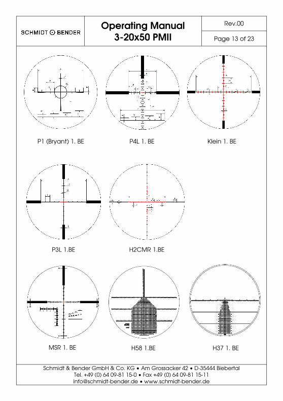
In the previously considered example the distance between the big hollow bars is 100cm / 10 x 20 = 200cm in 100m distance on magnification 10. The reticle coverages for the different reticles can be obtained from the following figures and tables.
P4L 2. BE P3L (Mil Dot) 2. BE P4L fine 1. BE
Operating Manual
3-20x50 PMII Rev.00
Page 13 of 23
Schmidt & Bender GmbH & Co. KG • Am Grossacker 42 • D-35444 Biebertal Tel. +49 (0) 64 09-81 15-0 • Fax +49 (0) 64 09-81 15-11 [email protected] • www.schmidt-bender.de
Klein 1. BE P1 (Bryant) 1. BE P4L 1. BE
P3L 1.BE H2CMR 1.BE
H58 1.BE H37 1. BE MSR 1. BE
Operating Manual
3-20x50 PMII Rev.00
Page 14 of 23
Schmidt & Bender GmbH & Co. KG • Am Grossacker 42 • D-35444 Biebertal Tel. +49 (0) 64 09-81 15-0 • Fax +49 (0) 64 09-81 15-11 [email protected] • www.schmidt-bender.de
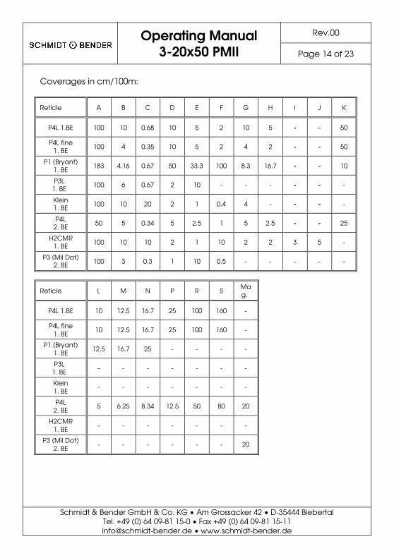
Coverages in cm/100m:
Reticle A B C D E F G H I J K
P4L 1.BE 100 10 0.68 10 5 2 10 5 - - 50
P4L fine 1. BE 100 4 0.35 10 5 2 4 2 - - 50
P1 (Bryant) 1. BE 183 4.16 0.67 50 33.3 100 8.3 16.7 - - 10
P3L 1. BE 100 6 0.67 2 10 - - - - - -
Klein 1. BE 100 10 20 2 1 0.4 4 - - - -
P4L 2. BE 50 5 0.34 5 2.5 1 5 2.5 - - 25
H2CMR 1. BE 100 10 10 2 1 10 2 2 3 5 -
P3 (Mil Dot) 2. BE 100 3 0.3 1 10 0.5 - - - - -
Reticle L M N P R S Mag.
P4L 1.BE 10 12.5 16.7 25 100 160 -
P4L fine 1. BE 10 12.5 16.7 25 100 160 -
P1 (Bryant) 1. BE 12.5 16.7 25 - - - -
P3L 1. BE - - - - - - -
Klein 1. BE - - - - - - -
P4L 2. BE 5 6.25 8.34 12.5 50 80 20
H2CMR 1. BE - - - - - - -
P3 (Mil Dot) 2. BE - - - - - - 20

Operating Manual
3-20x50 PMII Rev.00
Page 15 of 23
Schmidt & Bender GmbH & Co. KG • Am Grossacker 42 • D-35444 Biebertal Tel. +49 (0) 64 09-81 15-0 • Fax +49 (0) 64 09-81 15-11 [email protected] • www.schmidt-bender.de
Coverages in inch/100yards:
Reticle A B C D E F G H I J K
P4L 1.BE 36.0 3.60 0.24 3.60 1.80 0.72 3.60 1.80 - - 18.0
P4L fine 1. BE 36.0 1.44 0.13 3.60 1.80 0.72 1.44 0.72 - - 18.0
P1 (Bryant) 1. BE 65.8 1.50 0.24 18.0 12.0 36.0 2.99 6.01 - - 3.60
P3L 1. BE 36.0 2.16 0.24 0.72 3.60 - - - - - -
Klein 1. BE 36.0 3.60 7.20 0.72 0.36 0.14 1.44 - - - -
P4L 2. BE 18.0 1.80 0.12 1.80 0.90 0.36 1.80 0.90 - - 9.00
H2CMR 1. BE 36.0 3.60 3.60 0.72 0.36 3.60 0.72 0.72 1.08 1.80 -
P3 (Mil Dot) 2. BE 36.0 1.08 0.11 0.36 3.60 0.18 - - - - -
Reticle L M N P R S Mag.
P4L 1.BE 3.60 4.50 6.01 9.00 36.0 57.6 -
P4L fine 1. BE 3.60 4.50 6.01 9.00 36.0 57.6 -
P1 (Bryant) 1. BE 4.50 6.01 9.00 - - - -
P3L 1. BE - - - - - - -
Klein 1. BE - - - - - - -
P4L 2. BE 1.80 2.25 3.00 4.50 18.0 28.8 7.20
H2CMR 1. BE - - - - - - -
P3 (Mil Dot) 2. BE - - - - - - 7.20
Operating Manual
3-20x50 PMII Rev.00
Page 16 of 23
Schmidt & Bender GmbH & Co. KG • Am Grossacker 42 • D-35444 Biebertal Tel. +49 (0) 64 09-81 15-0 • Fax +49 (0) 64 09-81 15-11 [email protected] • www.schmidt-bender.de
5. Correction of the point of impact
5.1 Using the MTC LT Turrets
The MTC LT turrets include the following features:
• Double turn (elevation) • MTC (more tactile click) • Zero stop (elevation and windage) • Locking function (elevation and windage)
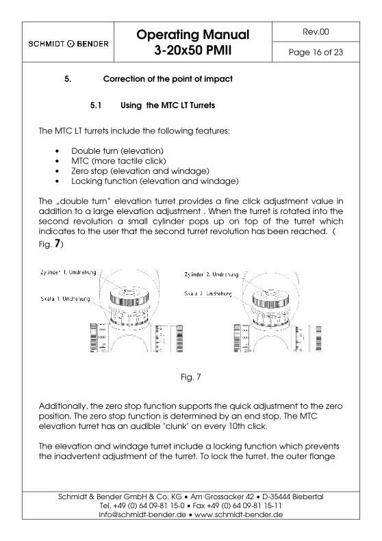
The „double turn“ elevation turret provides a fine click adjustment value in addition to a large elevation adjustment . When the turret is rotated into the second revolution a small cylinder pops up on top of the turret which indicates to the user that the second turret revolution has been reached. (
Fig. 7)
Fig. 7
Additionally, the zero stop function supports the quick adjustment to the zero position. The zero stop function is determined by an end stop. The MTC elevation turret has an audible "clunk" on every 10th click. The elevation and windage turret include a locking function which prevents the inadvertent adjustment of the turret. To lock the turret, the outer flange
Operating Manual
3-20x50 PMII
Schmidt & Bender GmbH & Co. KG • Am Grossacker 42 • D-35444 BiebertalTel. +49 (0) 64 09-81 15-0 • Fax +49 (0) 64 09-81 [email protected] • www.schmidt-bender.de
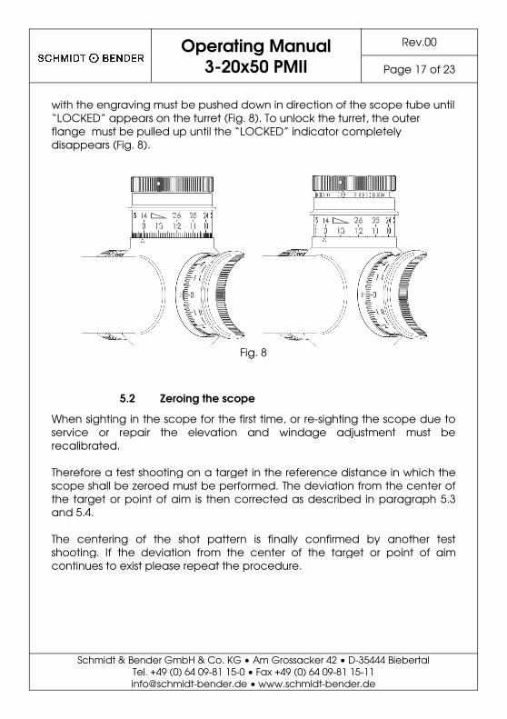
with the engraving must be pushed down in direction of the scope tube until “LOCKED” appears on the turret (Fig. 8). To unlock the turret, the outer flange must be pulled up until the “LOCKED” indicator completely disappears (Fig. 8).
Fig. 8
5.2 Zeroing the scope
When sighting in the scope for the first time, or re-sighting the scope due to service or repair the elevation and windage adjustment must be recalibrated. Therefore a test shooting on a target in the reference distance in which the scope shall be zeroed must be performed. The deviation from the centerthe target or point of aim is then corrected as described in and 5.4. The centering of the shot pattern is finally confirmed by another test shooting. If the deviation from the center of the target or point of aim continues to exist please repeat the procedure.
Rev.00
Page 17 of 23
35444 Biebertal 11
bender.de
pushed down in direction of the scope tube until ). To unlock the turret, the outer
ntil the “LOCKED” indicator completely
sighting the scope due to adjustment must be
Therefore a test shooting on a target in the reference distance in which the scope shall be zeroed must be performed. The deviation from the center of
as described in paragraph 5.3
is finally confirmed by another test shooting. If the deviation from the center of the target or point of aim
Operating Manual
3-20x50 PMII Rev.00
Page 18 of 23
Schmidt & Bender GmbH & Co. KG • Am Grossacker 42 • D-35444 Biebertal Tel. +49 (0) 64 09-81 15-0 • Fax +49 (0) 64 09-81 15-11 [email protected] • www.schmidt-bender.de
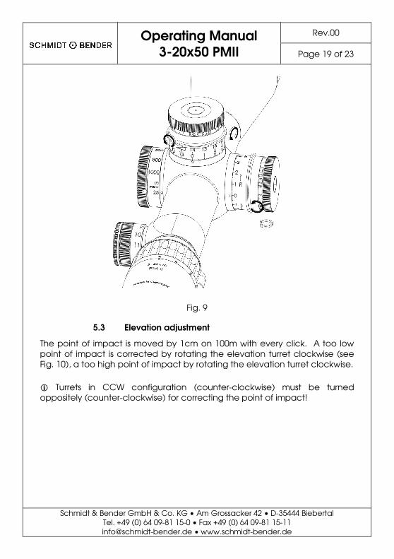
Lock both turrets, elevation and windage, then loosen the two Allen head screws in the outside diameter in line with the “LOCKED” signage using an Allen key (see Fig. 9). Now unlock the turrets by pulling up the outer bushing with the engraving and turn both turrets until the engraved “0” is indicated by the triangle on the saddle. The clicks of the turrets can be felt and heard when the screws are unlocked. This has no impact on the process of zeroing as the reticle does not move while the setscrews are loose. Now, lock the turrets by pushing down the outer bushing with the engraving and tighten the two Allen head screws with an Allen key. � The elevation turret must be in the first revolution. The turret caps are
secured by an additional screw and should NEVER be removed! The clicks of the turrets can be felt and heard when the screws are unlocked. This has no impact on the process of zeroing as the thread piece does not move while the setscrews are loose.
Operating Manual
3-20x50 PMII
Schmidt & Bender GmbH & Co. KG • Am Grossacker 42 • D-35444 BiebertalTel. +49 (0) 64 09-81 15-0 • Fax +49 (0) 64 09-81 [email protected] • www.schmidt-bender.de
Fig. 9
5.3 Elevation adjustment
The point of impact is moved by 1cm on 100m with every click. A too low point of impact is corrected by rotating the elevation turret clockwise (seeFig. 10), a too high point of impact by rotating the elevation turret clockwise. � Turrets in CCW configuration (counter-clockwise) mustoppositely (counter-clockwise) for correcting the point of impact!
Rev.00
Page 19 of 23
35444 Biebertal 11
bender.de
The point of impact is moved by 1cm on 100m with every click. A too low point of impact is corrected by rotating the elevation turret clockwise (see
), a too high point of impact by rotating the elevation turret clockwise.
must be turned the point of impact!
Operating Manual
3-20x50 PMII
Schmidt & Bender GmbH & Co. KG • Am Grossacker 42 • D-35444 BiebertalTel. +49 (0) 64 09-81 15-0 • Fax +49 (0) 64 09-81 [email protected] • www.schmidt-bender.de
Fig. 10
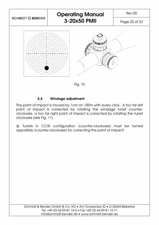
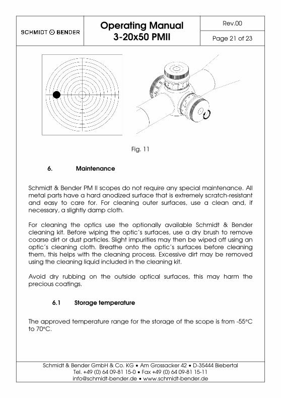
5.4 Windage adjustment
The point of impact is moved by 1cm on 100m with every click. A too far left point of impact is corrected by rotating the windage clockwise, a too far right point of impact is corrected by rotating the turret clockwise (see Fig. 11). � Turrets in CCW configuration (counter-clockwise) mustoppositely (counter-clockwise) for correcting the point of impact!
Rev.00
Page 20 of 23
35444 Biebertal 11
bender.de
The point of impact is moved by 1cm on 100m with every click. A too far left turret counter-
clockwise, a too far right point of impact is corrected by rotating the turret
must be turned ting the point of impact!
Operating Manual
3-20x50 PMII
Schmidt & Bender GmbH & Co. KG • Am Grossacker 42 • D-35444 BiebertalTel. +49 (0) 64 09-81 15-0 • Fax +49 (0) 64 09-81 [email protected] • www.schmidt-bender.de
Fig. 11
6. Maintenance
Schmidt & Bender PM II scopes do not require any special maintenance. All metal parts have a hard anodized surface that is extremely scratchand easy to care for. For cleaning outer surfaces, use a clean and, if necessary, a slightly damp cloth. For cleaning the optics use the optionally available Schmidt & Bender cleaning kit. Before wiping the optic’s surfaces, use a dry brush to remove coarse dirt or dust particles. Slight impurities may then be wiped off using an optic’s cleaning cloth. Breathe onto the optic’s surfaces before cleaning them, this helps with the cleaning process. Excessive dirt may be removed using the cleaning liquid included in the cleaning kit. Avoid dry rubbing on the outside optical surfaces, this may harm the precious coatings.
6.1 Storage temperature
The approved temperature range for the storage of the scope is from to 70°C.
Rev.00
Page 21 of 23
35444 Biebertal 11
bender.de
Schmidt & Bender PM II scopes do not require any special maintenance. All metal parts have a hard anodized surface that is extremely scratch-resistant and easy to care for. For cleaning outer surfaces, use a clean and, if
Schmidt & Bender cleaning kit. Before wiping the optic’s surfaces, use a dry brush to remove coarse dirt or dust particles. Slight impurities may then be wiped off using an
he onto the optic’s surfaces before cleaning them, this helps with the cleaning process. Excessive dirt may be removed
Avoid dry rubbing on the outside optical surfaces, this may harm the
The approved temperature range for the storage of the scope is from -55°C

Operating Manual
3-20x50 PMII Rev.00
Page 22 of 23
Schmidt & Bender GmbH & Co. KG • Am Grossacker 42 • D-35444 Biebertal Tel. +49 (0) 64 09-81 15-0 • Fax +49 (0) 64 09-81 15-11 [email protected] • www.schmidt-bender.de
7. Warranty certificate
We hereby certify that our Quality Management System has been approved by Unternehmensgruppe TUV Rheinland Berlin Brandenburg to the following Quality Management Standard: The TUV Cert Certification Body of TUV Anlagentechnik GmbH (Unternehmensgruppe TUV Rheinland Berlin Brandenburg) certifies in accordance with TUV Cert procedures that Schmidt & Bender GmbH & Co. KG, Am Grossacker 42, D-35444 Biebertal has established and applies a quality management system for the design, production sales and service of fine mechanical optical instruments. Main product telescopic sights. Proof has been furnished that the requirements according to ISO 9001 – 2008 Registration No. 01 100 67280 - are fulfilled. All parts have been thoroughly inspected in accordance with the afore-mentioned Quality Management System and correspond to the requirements of the specifications, drawings, test procedures and standards in all respects.S Guarantee clause: Official legal guarantee period of 2 years (according to the directive of EU) Contact:
Schmidt & Bender GmbH & Co. KG • Am Grossacker 42 • D-35444 Biebertal • Germany Tel. +49 (0) 64 09-81 15-0 • Fax +49 (0) 64 09-81 15-11 [email protected] • www.schmidt-bender.de Schmidt & Bender Inc. • 741 Main Street • Claremont, NH 03743 • U.S.A. Tollfree (800)468-3450 • Phone +1(603)287-4830 • Fax (603)287-4832 [email protected]

Operating Manual
3-20x50 PMII Rev.00
Page 23 of 23
Schmidt & Bender GmbH & Co. KG • Am Grossacker 42 • D-35444 Biebertal Tel. +49 (0) 64 09-81 15-0 • Fax +49 (0) 64 09-81 15-11 [email protected] • www.schmidt-bender.de
Notes __________________________________________________________________________ __________________________________________________________________________ __________________________________________________________________________ __________________________________________________________________________ __________________________________________________________________________ __________________________________________________________________________ __________________________________________________________________________ __________________________________________________________________________ __________________________________________________________________________ __________________________________________________________________________ __________________________________________________________________________ __________________________________________________________________________ __________________________________________________________________________ __________________________________________________________________________ __________________________________________________________________________ __________________________________________________________________________ __________________________________________________________________________ __________________________________________________________________________ _________________________________________________________________________

Schmidt & Bender GmbH & Co. KG • Am Grossacker 42 • D-35444 Biebertal Tel. +49 (0) 64 09-81 15-0 • Fax +49 (0) 64 09-81 15-11 [email protected] • www.schmidt-bender.de