Embed Size (px)
Citation preview
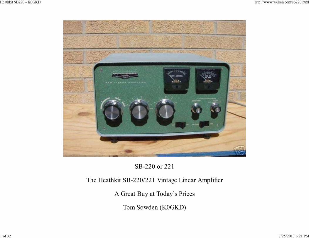
SB-220 or 221
The Heathkit SB-220/221 Vintage Linear Amplifier
A Great Buy at Today’s Prices
Tom Sowden (K0GKD)
Heathkit SB220 - K0GKD http://www.w6kan.com/sb220.html
1 of 32 7/25/2013 6:21 PM

www.k0gkd.com
QST January 2007
With the sun cycle heading towards its eleven year low many hams will be turning to 40 and 80 meters
for contacts and enjoying the hobby. Getting through the QRM can often make the difference in
enjoying a good solid QSO in today’s crowded bands. Also it just feels great to get good signal reports.
With prices for new commercial linear amplifiers right up there with new solid state transceivers,
considering used vintage equipment presents an option that works a lot better for those of us with
limited budgets. I suspect that many amateurs are fearful that older amplifiers will not work, or if they
do, not for long. If you understand the circuits and get comfortable with the nuances of the older
vintage radios you can keep them going for years with a minimum of effort, and they will perform with
the best of the commercial units watt for watt.
Heathkit produced thousands of the models SB 220 and SB221, 20 plus years ago, and there are still
many of these units on the market today. Using a pair of Eimac 3-500Z’s they put out an amazing
punch doing yeoman’s duty on a daily basis, and can be driven to the legal limit with 100 watts. These
amplifiers often sell for around $600 or less. When you consider that a comparable commercial
amplifier costs upwards of three to four times this amount they represent a great value.
I recently purchased a SB221 on Ebay for $450. The added freight brought the total to over $500.
Naturally I was concerned about the power transformer so I e-mailed the seller before bidding to ask
about its condition. He would only certify that when the amplifier was turned on the power meter
indicated about 2,700 volts, and the tubes lit up. That was enough to convince me that the power unit
was okay. When the Heathkit SB221 arrived I took it apart and started a visual examination. A good
rule to follow with used equipment is to never plug it in without first inspecting the components
thoroughly, and running whatever tests seem necessary.
Heathkit SB220 - K0GKD http://www.w6kan.com/sb220.html
2 of 32 7/25/2013 6:21 PM

When working with high voltage equipment safety should be in your thoughts at all times. I follow
rules due to the dangerous potentials involved. They are:
Never work on the unit when it is connected to a source of electricity.
Use a “chicken stick” (QST September 2003) to make sure every contact that you intend to touch
with your hands is not “alive”. This is especially important around the high voltage section where
electrolytic capacitors could be still charged if the bleeding resistors have not dissipated the
stored voltage. Often the “bleeder” resistors are non functional or the solder joints have come
undone leaving the capacitor charged with very dangerous voltages. (Note: add a 10 ohm, 10 watt
resistor in series with the 12 gauge wire to avoid discharging charged capacitors too fast and
damaging them).
Chicken Stick
Heathkit SB220 - K0GKD http://www.w6kan.com/sb220.html
3 of 32 7/25/2013 6:21 PM
I wear rubber-soled shoes so that my feet are not grounded. I never stand on a wet surface for
obvious reasons.
If possible, I only use one hand keeping the other more or less behind my back. If this is not
possible I do a double grounding check with the “chicken stick” to once again make sure there are
no voltages present on the areas that I may contact.
I never work on amplifiers if I am tired.
It helps me to better understand problems that may arise if I know the basic flow of the schematic. The
only way I can sort out understanding circuits is to divide them into segments. While a lot of what
follows is fairly basic to a lot of hams, thoroughly understanding the circuit helps with potential
problems and repairs. Lets start with the high voltage supply, and segment this from the overall
schematic.
Heathkit SB220 - K0GKD http://www.w6kan.com/sb220.html
4 of 32 7/25/2013 6:21 PM
Heathkit SB220 - K0GKD http://www.w6kan.com/sb220.html
5 of 32 7/25/2013 6:21 PM
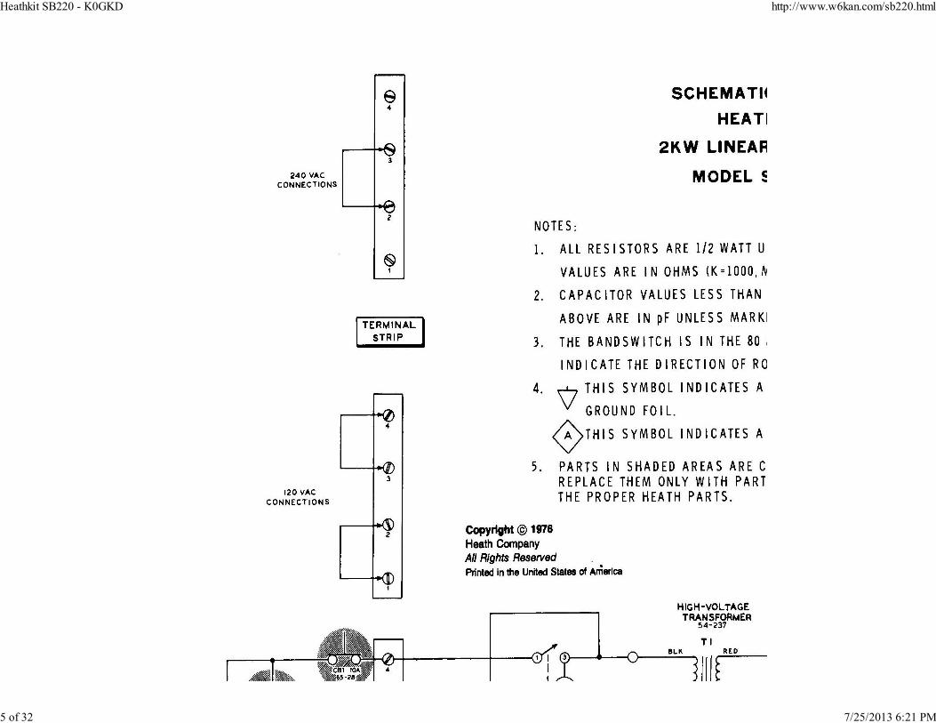
High Voltage Transformer
Note: I received the following email from K5JV regarding an error in the HK schematic:
I want to point out one very important possible oversight that, I think, is very important. The SB-220 schematic you show has a very
glaring error. It shows the AC circuit breakers in the wrong place, It shows them to be in the main AC line which would require different
values of CB/fuse when switching between 120 and 240 VAC power. The CB's should be on the other side of the voltage selector strip, thus
placing them in one of the individual transformer primaries, not the main AC line, which feeds both primaries. This way, the CB's do not
have to be changes when switching between 120 and 240 VAC power because they are only protecting one of the transformer primaries
each ( always the same whether the primaries are in series, or parallel.
A look at the transformer connections indicates the manner in which one can use either 110VAC or
220VAC because of the dual primary windings. If 220VAC is the choice the primary windings are
simply connected at the mid-point (2 & 3) in series so that they appear and act like a single winding.
Conversely, the midpoints can be wired in parallel for 110VAC (1 & 2, 3 & 4). You can see what the
engineers were doing by lowering the ratio in half between the primary and secondary for 220VAC, and
doubling it for 110VAC. This, of course, results in the same voltage across the secondary of the
transformer windings. Note the switch on the primary windings. This is to lower the high voltage for the
heavier duty cycle required using the CW mode. By tapping down the primary windings the ratio to the
secondary drops causing the secondary voltage to decrease.
Due to the current demands I strongly recommend using 220VAC, otherwise you may dim the lights
and blow out the 110VAC service to the shack. It is real easy to run the higher voltage to the shack as
almost all homes have 220VAC service to the main breaker. I placed a separate circuit breaker nearby
that is wired with a feed line to a female plug to accommodate the linear. The amplifier should have an
appropriate male plug. This will allow you to disconnect the power leads by simply throwing out the
circuit breaker, and unplugging the unit. Most hardware stores carry 15 amp disconnects which work
well with the 220VAC option. A plug designed for 220VAC should be purchased if you plan on
connecting to this voltage. Keep in mind that each leg of the 220VAC measures 110-120VAC to
Heathkit SB220 - K0GKD http://www.w6kan.com/sb220.html
6 of 32 7/25/2013 6:21 PM

ground, and 220-240VAC across the two elements. When wiring the plug, normally the green wire is
connected to ground, and the white and black wires to the respective terminals.
The high voltage power supply circuit theory is fairly conventional. The secondary windings have about
a 8:1 or 4:1 ratio to the primary windings – depending on how you wired the primary. The root mean
square voltages across the secondary are going to be about the same at 960 VAC (4 x 240VAC or 8 x
120VAC), or more if the line voltage is higher.
Most amplifiers use voltage-doubling circuits to avoid very high voltage transformers, which are
expensive. The SB 220 is no exception. To fully understand how these work one only has to follow the
flow of electricity during the duty cycle of the AC. Lets examine this for a better comprehension of the
factors involved.
AC Duty Cycle
We know that household electricity is alternating current at 60 cycles per second. During the positive
phase the voltage starts at zero and quickly rises to its peak of about 158 volts (note: when we measure
AC voltages we are looking at the average or root mean square of the voltage, not its peak which is
about 1.414 times greater). As the voltage rises and falls across the primary it sets up a magnetic field,
which induces voltage in the secondary of the transformer in relationship to the ratio of the windings.
In the case of the SB220 the RMS voltage of 960 VAC will peak at 1,357VAC (1.414 * 960).
Heathkit SB220 - K0GKD http://www.w6kan.com/sb220.html
7 of 32 7/25/2013 6:21 PM
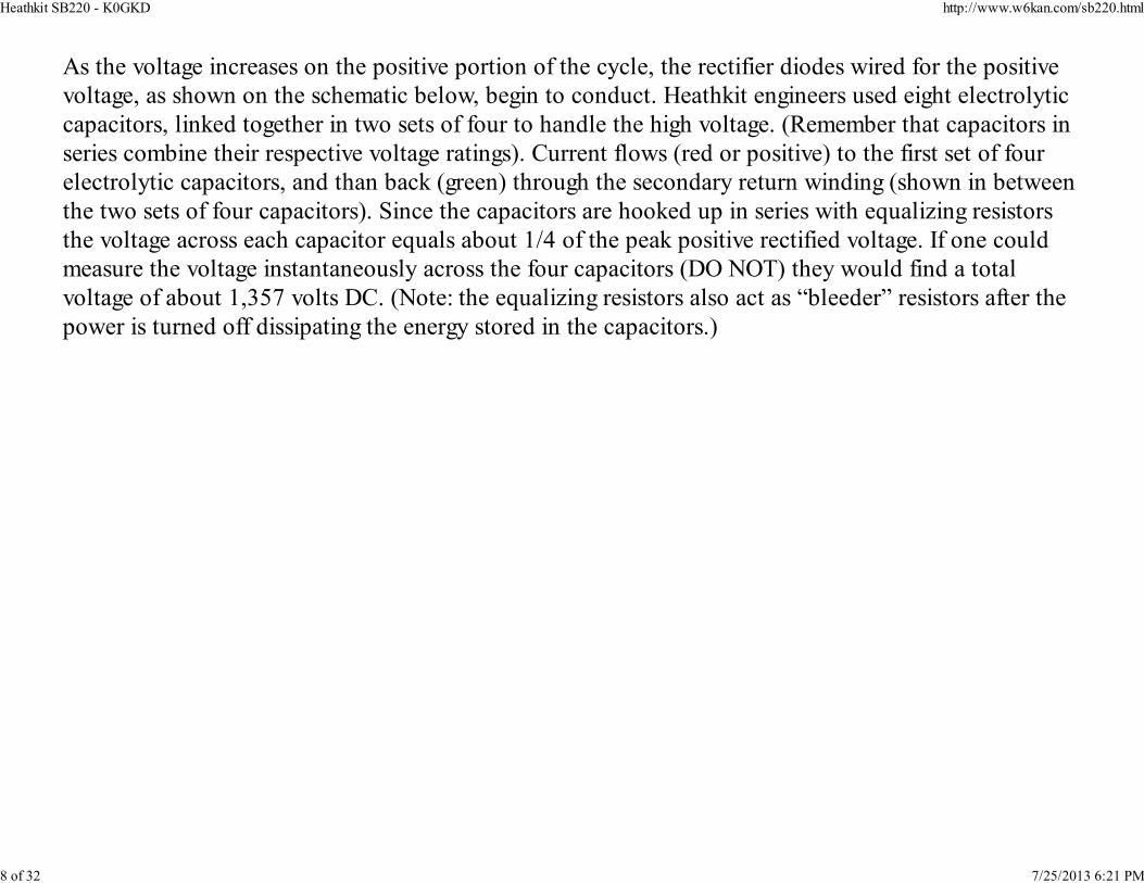
As the voltage increases on the positive portion of the cycle, the rectifier diodes wired for the positive
voltage, as shown on the schematic below, begin to conduct. Heathkit engineers used eight electrolytic
capacitors, linked together in two sets of four to handle the high voltage. (Remember that capacitors in
series combine their respective voltage ratings). Current flows (red or positive) to the first set of four
electrolytic capacitors, and than back (green) through the secondary return winding (shown in between
the two sets of four capacitors). Since the capacitors are hooked up in series with equalizing resistors
the voltage across each capacitor equals about 1/4 of the peak positive rectified voltage. If one could
measure the voltage instantaneously across the four capacitors (DO NOT) they would find a total
voltage of about 1,357 volts DC. (Note: the equalizing resistors also act as “bleeder” resistors after the
power is turned off dissipating the energy stored in the capacitors.)
Heathkit SB220 - K0GKD http://www.w6kan.com/sb220.html
8 of 32 7/25/2013 6:21 PM
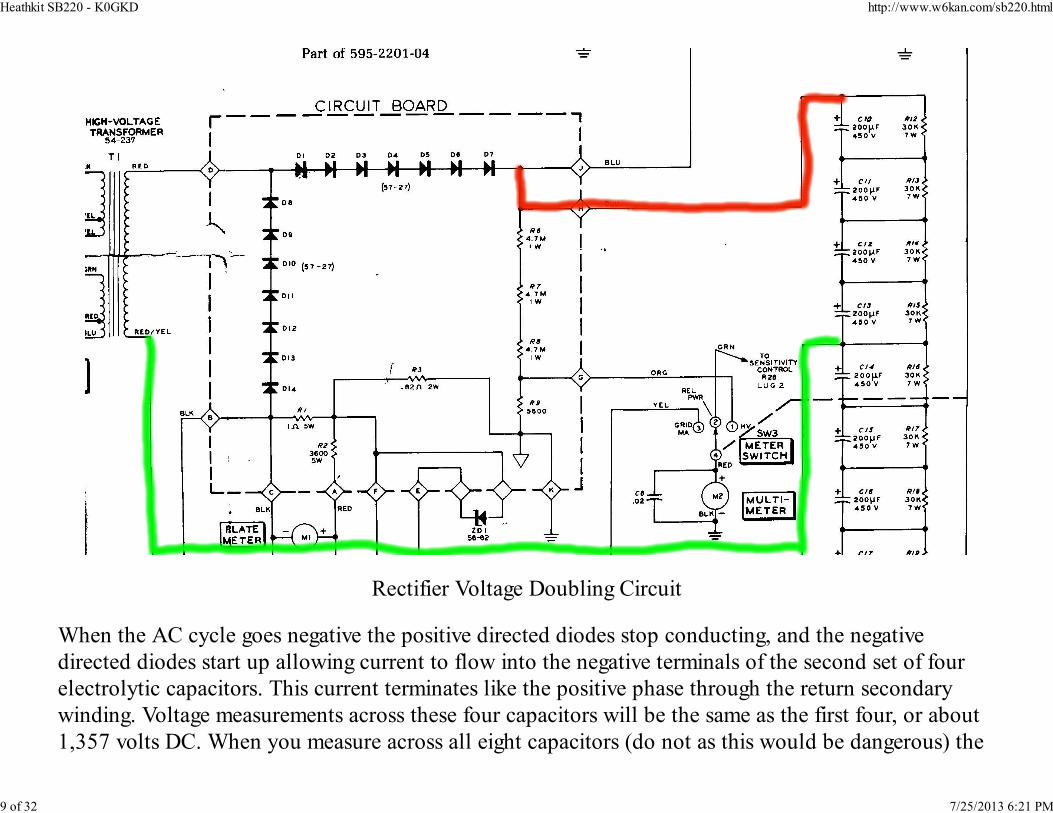
Rectifier Voltage Doubling Circuit
When the AC cycle goes negative the positive directed diodes stop conducting, and the negative
directed diodes start up allowing current to flow into the negative terminals of the second set of four
electrolytic capacitors. This current terminates like the positive phase through the return secondary
winding. Voltage measurements across these four capacitors will be the same as the first four, or about
1,357 volts DC. When you measure across all eight capacitors (do not as this would be dangerous) the
Heathkit SB220 - K0GKD http://www.w6kan.com/sb220.html
9 of 32 7/25/2013 6:21 PM
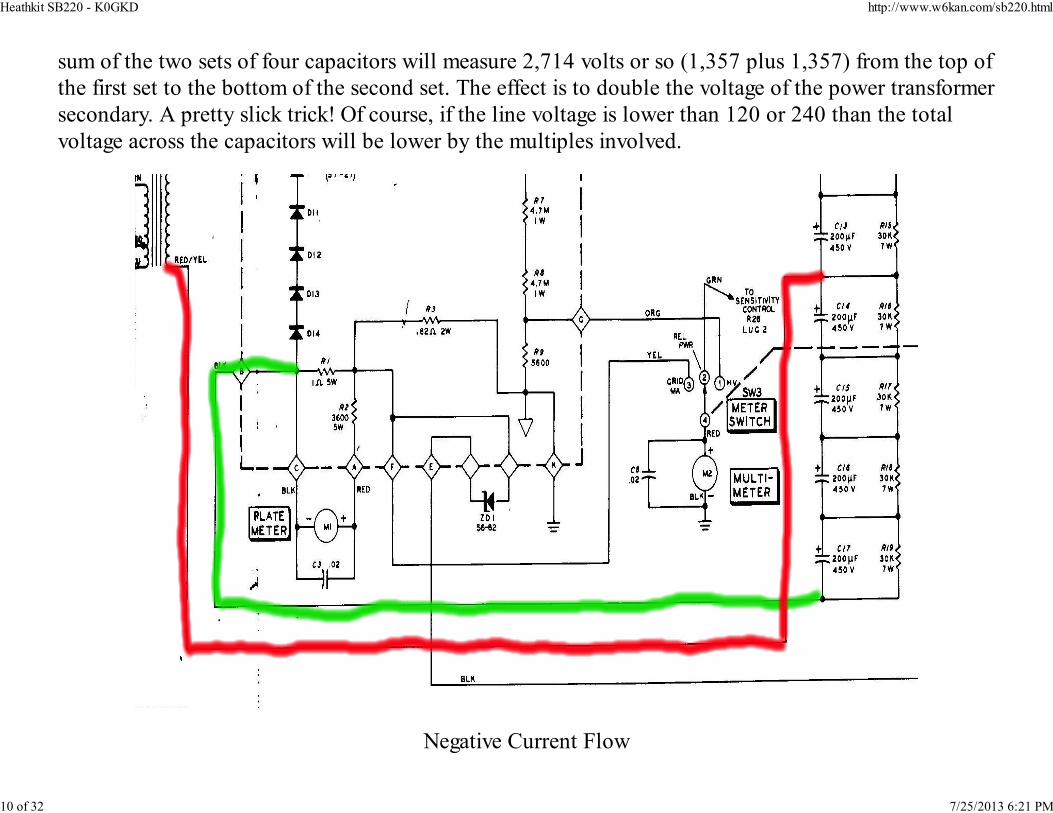
sum of the two sets of four capacitors will measure 2,714 volts or so (1,357 plus 1,357) from the top of
the first set to the bottom of the second set. The effect is to double the voltage of the power transformer
secondary. A pretty slick trick! Of course, if the line voltage is lower than 120 or 240 than the total
voltage across the capacitors will be lower by the multiples involved.
Negative Current Flow
Heathkit SB220 - K0GKD http://www.w6kan.com/sb220.html
10 of 32 7/25/2013 6:21 PM
This type of circuit is used in many different applications to double, triple, or quadruple voltages. The
main disadvantage of these circuits is voltage regulation where relatively high current demands can
draw down the stored energy. This is understandable if you think of the capacitors as if they were
batteries. Of course, the more capacity they have the more they can deliver without dropping the
voltage too much. Heathkit engineers tended to use electrolytic filter capacitors with only about 200
microfarads. Since there are a total of eight capacitors, effectively in series, the net capacity is about 25
microfarads (200uf/8). This tends to allow the high voltage to drop 10% or more on key down or on
SSB voice peaks. Although this voltage drop is not acutely noticeable at the receiving end, it does
impact the linearity of the amplifier nominally, and to some degree the audio quality.
With computer grade electrolytic capacitors available at reasonable prices I like to replace the older
capacitors with brand new ones that have considerably higher capacitance. Replacing these older parts
is a good idea anyway as more than likely they are "leaky" and probably the same age as the linear.
There are usually telltale indications of age with signs of heat stress where the containers have
expanded. In my modification I replaced the original eight with new capacitors that were rated at 100
degrees C, 500 volts at 450 microfarads each. I hooked them in series, just like the original circuit. The
net capacity works out to 450 divided by 8, or 56+ufd. That calculates to more than two times the
original HK total of 25ufd! I got them all to fit into the original casing. The new ones were about half
the length, and the same diameter, compared to the originals. The net result of the additional filter
capacity is better regulation. On voice peaks there is a nominal drop (about 10%) in the B+ going to the
3-500Z's. The amp seems to have more power, and the reports are very good.
Some hams recommend replacing the bleeder resistors with higher values, like 100,000 ohms, in order
to reduce the heat dissipation from the wire wound 30,000 ohm original resistors. There are two sides
to this issue - one is that the combined resistance of 800,000 ohms is too much for a "bleeder", and
100,000 ohms will not balance the voltages across the capacitor bank evenly if there is unusually high
leakage. On the other side is the heat issue with less total resistance. My own experience has been good
Heathkit SB220 - K0GKD http://www.w6kan.com/sb220.html
11 of 32 7/25/2013 6:21 PM
with the 100K option but adding a less resistive bleeder resistor makes sense from a safety point of
view. If the original 30K resistors are mounted with a reasonable amount of clearance they will remain
cool through convection air currents. Considering the factors for both approaches I would tend to
recommend staying with the original 30K wire wound resistors. With the computer grade electrolytics
rated at 100 degrees C the bleeder resistor temperature transfer should not cause a problem. This is
better for votage regulation and safety due to the quick discharge of the capacitor bank when the power
is turned off.
One consequence of the higher net capacity is the surge of current it takes to charge the capacitors
when you first turn the amplifier on. This can be somewhat stressful on the power transformer. I
installed a “surge” circuit to negate this affect. By placing a 10 ohm 30 watt wire wound resistors
across the contacts of a "hockey puck" solid state relay, and than providing a delay circuit to activate
the relay for about two seconds, I had a good surge solution. The relay was placed between the power
switch and one side of the 220VAC. Since I needed a source of DC for the delay circuit I changed the
original voltage divider set up across the bias supply so that I would have about 8-12VDC - no load.
The original divider was used to provide about 60VDC for the ALC circuit which is not needed due to
the relative low power of most modern "driving" transceivers.
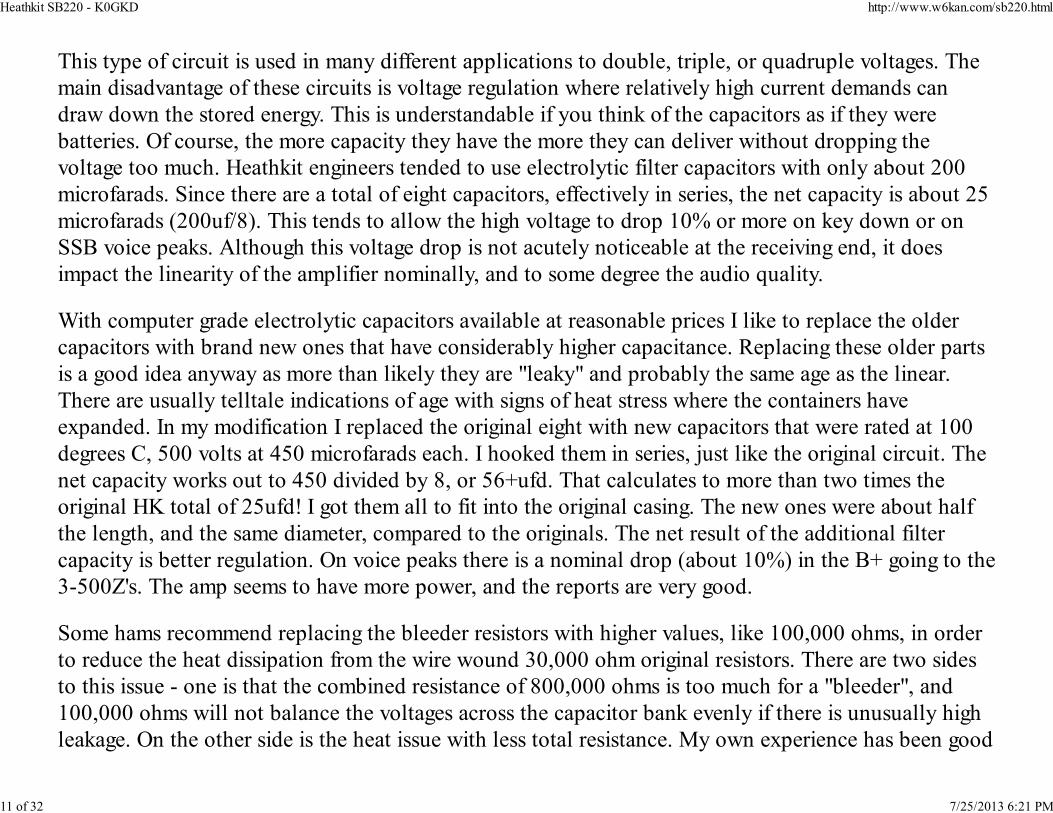
By changing R3 and R4 to 2,000 ohms and 7,000 ohms (2 watt composition) the voltage at the divided junction is
Heathkit SB220 - K0GKD http://www.w6kan.com/sb220.html
12 of 32 7/25/2013 6:21 PM
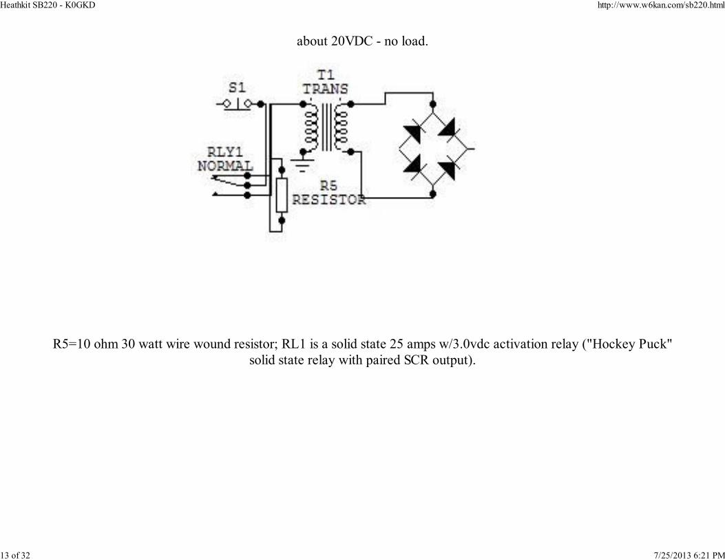
about 20VDC - no load.
R5=10 ohm 30 watt wire wound resistor; RL1 is a solid state 25 amps w/3.0vdc activation relay ("Hockey Puck"
solid state relay with paired SCR output).
Heathkit SB220 - K0GKD http://www.w6kan.com/sb220.html
13 of 32 7/25/2013 6:21 PM
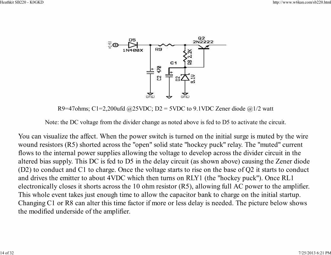
R9=47ohms; C1=2,200ufd @25VDC; D2 = 5VDC to 9.1VDC Zener diode @1/2 watt
Note: the DC voltage from the divider change as noted above is fed to D5 to activate the circuit.
You can visualize the affect. When the power switch is turned on the initial surge is muted by the wire
wound resistors (R5) shorted across the "open" solid state "hockey puck" relay. The "muted" current
flows to the internal power supplies allowing the voltage to develop across the divider circuit in the
altered bias supply. This DC is fed to D5 in the delay circuit (as shown above) causing the Zener diode
(D2) to conduct and C1 to charge. Once the voltage starts to rise on the base of Q2 it starts to conduct
and drives the emitter to about 4VDC which then turns on RLY1 (the "hockey puck"). Once RL1
electronically closes it shorts across the 10 ohm resistor (R5), allowing full AC power to the amplifier.
This whole event takes just enough time to allow the capacitor bank to charge on the initial startup.
Changing C1 or R8 can alter this time factor if more or less delay is needed. The picture below shows
the modified underside of the amplifier.
Heathkit SB220 - K0GKD http://www.w6kan.com/sb220.html
14 of 32 7/25/2013 6:21 PM
Heathkit SB220 - K0GKD http://www.w6kan.com/sb220.html
15 of 32 7/25/2013 6:21 PM
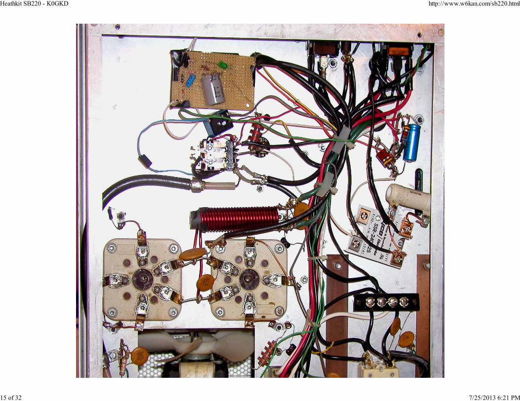
Starting from twelve o'clock and going clockwise - the delay circuit, the voltage divider across the bias supply, the 10
ohm 30 watt wire wound resistor across the "hockey puck" relay, the now "grounded grids" with copper wire, the rf
choke feeding the filaments (above the tube sockets), and the T/R relay.
If you decide to replace the capacitors in the circuit make sure you connect the correct polarity –
positive or negative. The electrolytic capacitors are marked with either a “-“ or “+” sign by the
respective terminals. If you are not sure of the circuit board polarity just double-check the schematic
with the capacitor placement. The wiring is somewhat complicated so you might want to make a
drawing of the original hookup to follow during the replacement.
Heathkit SB220 - K0GKD http://www.w6kan.com/sb220.html
16 of 32 7/25/2013 6:21 PM
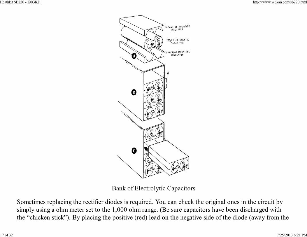
Bank of Electrolytic Capacitors
Sometimes replacing the rectifier diodes is required. You can check the original ones in the circuit by
simply using a ohm meter set to the 1,000 ohm range. (Be sure capacitors have been discharged with
the “chicken stick”). By placing the positive (red) lead on the negative side of the diode (away from the
Heathkit SB220 - K0GKD http://www.w6kan.com/sb220.html
17 of 32 7/25/2013 6:21 PM
arrow marking), and the black or negative lead on the positive marking you should read a very low
resistance. Reversing the leads of the ohmmeter should show a much higher resistance. By checking
each diode this way you can insure that they are all functional. Diodes that have broken down due to
voltage or current excesses almost always show a direct short. If you replace them do so with higher
values than the original diodes, and replace all of them. I like to use the ones that have at least a
three-amp current rating at over 1,000 volts. You can buy them for about $0.35 each. Keep in mind
they are hooked up in series so they can take the high voltage across the capacitor bank of
approximately 3,000 VDC. Eight 1,000 PIV rated diodes, four for the positive cycle, and four for the
negative cycle will give you more than adequate margin (4 x 1,000) to handle the high voltage. There
have been articles written about shunting each diode with a ½ watt 470k resistor, and a .01uf 1kv
bypass capacitor. If the diodes are the same type and are sourced from the same manufacturer this is not
necessary as the internal junction capacity of each of the diodes will be nearly the same. On the other
hand, if you use dissimilar diodes than you will want to add the resistor and capacitor across each
diode.
You might also want to change out the bias filter capacitor too. Like the high-powered rectifier ones, it
will likely fail in time due to age – mostly they tend to dry out over time. You can usually find a
substitute in the parts box that will handle the voltage (150VDC). Make sure the positive side is
connected as indicated. Also check the rectifier with the positive/negative leads of the ohmmeter to
make sure it has not shorted out due to excess current or voltage.
The bias supply for the SB220 uses positive DC voltage rectified off of T2, which also operates the K1
relay and supplies the ALC threshold voltage.
Heathkit SB220 - K0GKD http://www.w6kan.com/sb220.html
18 of 32 7/25/2013 6:21 PM
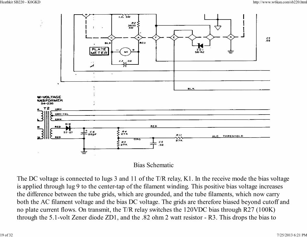
Bias Schematic
The DC voltage is connected to lugs 3 and 11 of the T/R relay, K1. In the receive mode the bias voltage
is applied through lug 9 to the center-tap of the filament winding. This positive bias voltage increases
the difference between the tube grids, which are grounded, and the tube filaments, which now carry
both the AC filament voltage and the bias DC voltage. The grids are therefore biased beyond cutoff and
no plate current flows. On transmit, the T/R relay switches the 120VDC bias through R27 (100K)
through the 5.1-volt Zener diode ZD1, and the .82 ohm 2 watt resistor - R3. This drops the bias to
Heathkit SB220 - K0GKD http://www.w6kan.com/sb220.html
19 of 32 7/25/2013 6:21 PM
about 5VDC and allows the 3-500Z's idle plate current to rise to about 125 milliamps.
A filament to grid short in the 3-500Z can cause a lot of damage a usually takes out ZD1, the Zener
diode that provides bias for the tubes and reduces the idle current. Also it is often burned because it
grounded out on its mounting. If you look carefully you will see that there is a mylar washer and feed
through sleeve keeping it insulated from the chassis. Over time the insulating media wears thin and can
short out frying the device.
It is important to understand how the Zener diode works. Unlike a conventional diode the Zener is
designed to breakdown once a pre-engineered voltage is reached - in the ZD1 instance about 5vdc. The
diode is "inverted" (a normal diode would not conduct positive voltage in this configuration) in the
circuit as shown below.
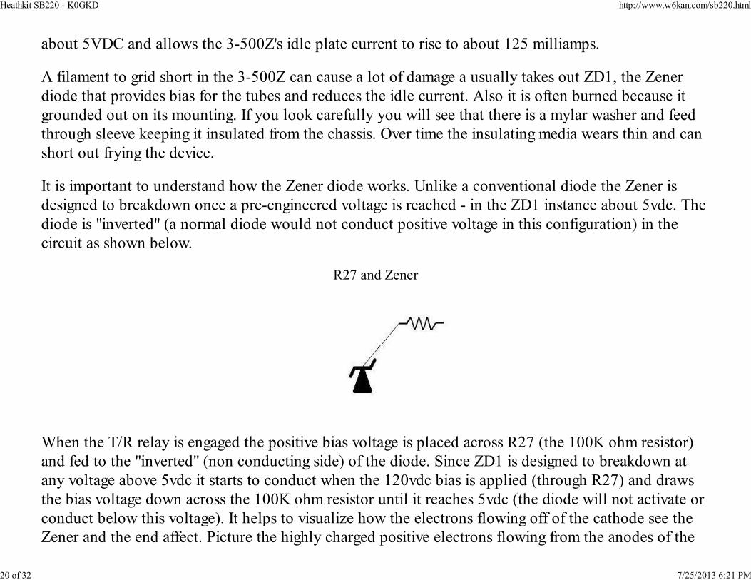
R27 and Zener
When the T/R relay is engaged the positive bias voltage is placed across R27 (the 100K ohm resistor)
and fed to the "inverted" (non conducting side) of the diode. Since ZD1 is designed to breakdown at
any voltage above 5vdc it starts to conduct when the 120vdc bias is applied (through R27) and draws
the bias voltage down across the 100K ohm resistor until it reaches 5vdc (the diode will not activate or
conduct below this voltage). It helps to visualize how the electrons flowing off of the cathode see the
Zener and the end affect. Picture the highly charged positive electrons flowing from the anodes of the
Heathkit SB220 - K0GKD http://www.w6kan.com/sb220.html
20 of 32 7/25/2013 6:21 PM

3-500Zs trying to find their return to ground. Flowing through the cathodes to the center tap of the
filament transfomer they first encounter the Zender diode. They flow on through the diode but are
limited by the Zener which leaves 5vdc (more or less) as reverse bias on the cathodes. This limits the
idle current the tubes conduct in a "no-drive" sate. Although the 3-500Z's are designed for a "no bias
state" (up to about 3,000VDC on the plates), they tend to draw too much idle current without the
limiting effect of the Zener diode. With the Zener in place the idle current should be around 100ma in
the "no drive" state. The current across the ZD1 is approximately 120 milliamps so it needs to be a
fairly hefty device. Remember that the Zener must be insulated from the chassis and note the direction
of the arrow imprinted so that you can make the proper connection - the arrow needs to be pointing to
the black wire that is connected to the T/R relay and R27. It is wired through the circuit board next to
the ZD1 symbol.
Some manuals show ZD1 mounted on the rectifier diode board, but it was later removed due to heat
considerations. It should be mounted on the side aluminum panel, which acts as a heat sink, adjoining
the rectifier diodes. It has a feed through insulator to keep the mounting bolt from coming in contact
with the panel, and a Mylar washer for the mounting nut. The Zener diode must be kept insulated
from the chassis. If you need a replacement it can be ordered from RF Parts (1N3996A with
hardware). If you replace it test it with a volt/ohm meter from the stud side to ground - it should show
"open" (make sure the test is made before it is connected to the circuit board). Also take note that the
connection to the stud side of the diode (away from the arrow) must be made in front of the Mylar
washer and not touching the chassis! It is also a good idea to check the .82 ohm resistor that is in series
with the "negative side" (away from the arrow - this resistor is one sided to ground and comes into play
when the ZD1 conducts in the transmit mode) of the diode. Often if the Zener goes out it will take the
.82 ohm two watt resistor out too. If you have to replace ZD1 you might consider adding a 1 amp fuse
in series on the side away from the positive arrow. Short the fuse with a 10k one watt resistor so that if
it blows the resistor will keep bias on the tube until it can be replaced. This little trick might save the
tubes in a filament to grid short!
Heathkit SB220 - K0GKD http://www.w6kan.com/sb220.html
21 of 32 7/25/2013 6:21 PM
A less expensive alternative to ZD1 is to use rectifier diodes strung up in series - about seven or eight
diodes. You can experiment with different numbers to get the idle current where you think it works best
- 100 to 150ma. Each diode will give you about 0.8 volts of bias, more or less. Use diodes that have
high current ratings such as 1N5408s - 1kv at 3 amps. Adding a one amp fuse in series with the diodes
(parallel the fuse with a 10k one watt composition resistor), just like with ZD1, adds another safety
element for a filament to grid short in the 3-500Zs. They can be mounted on perf board and easily
installed in place of the Zener diode. Make sure the arrows are pointing in the opposite direction of
ZD1. Rewire the T/R relay so the 100VDC is fed to the cathodes in the receive mode only and is not
switched to the Zener during transmit as originally wired. The diodes by themselves will provide all of
the bias needed in the transmit mode!
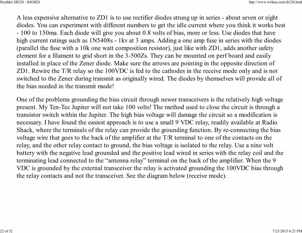
One of the problems grounding the bias circuit through newer transceivers is the relatively high voltage
present. My Ten-Tec Jupiter will not take 100 volts! The method used to close the circuit is through a
transistor switch within the Jupiter. The high bias voltage will damage the circuit so a modification is
necessary. I have found the easiest approach is to use a small 9 VDC relay, readily available at Radio
Shack, where the terminals of the relay can provide the grounding function. By re-connecting the bias
voltage wire that goes to the back of the amplifier at the T/R terminal to one of the contacts on the
relay, and the other relay contact to ground, the bias voltage is isolated to the relay. Use a nine volt
battery with the negative lead grounded and the positive lead wired in series with the relay coil and the
terminating lead connected to the “antenna relay” terminal on the back of the amplifier. When the 9
VDC is grounded by the external transceiver the relay is activated grounding the 100VDC bias through
the relay contacts and not the transceiver. See the diagram below (receive mode).
Heathkit SB220 - K0GKD http://www.w6kan.com/sb220.html
22 of 32 7/25/2013 6:21 PM
In my modification I used a 12VDC Radio Shack relay. I feed 12VDC from the transceiver into the amp through
ALC input jack (disconnected inside!)
The battery source indicated above seemed to be a good idea but in practice it had to be constantly
replaced. Alternatively, the Jupiter, as do most modern transceivers, has its supply voltage of
12-13.5VDC available at the back of the unit. If not go through your junk box and find a 12vdc (plus
or minus) wall-wort.You can use a 12-volt relay by providing the “transceiver” or wall-wort voltage to
activate the relay. The return lead for the 13.5VDC could be routed to ground through the transceiver’s
circuit. I use shielded cable for both the voltage and the antenna grounding wires to avoid the
possibility of picking up stray RF. Of course, if your transceiver can handle the higher bias voltage than
this modification is not necessary. If you are not sure than use the additional relay.
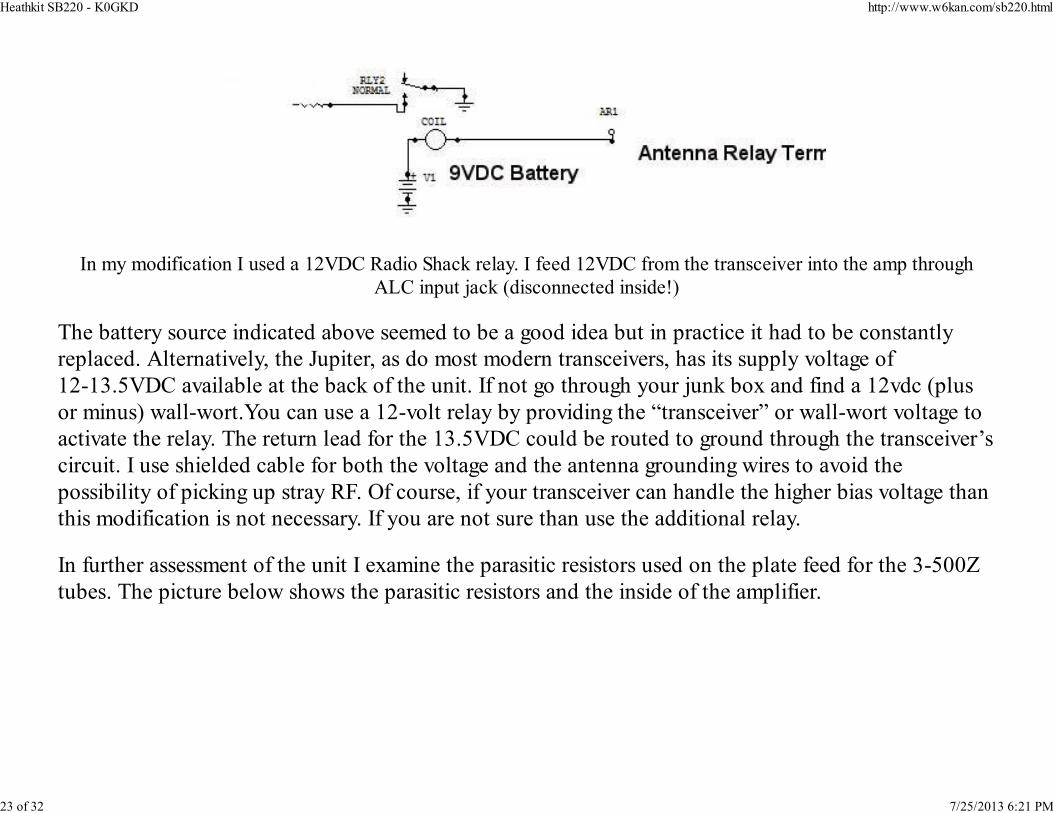
In further assessment of the unit I examine the parasitic resistors used on the plate feed for the 3-500Z
tubes. The picture below shows the parasitic resistors and the inside of the amplifier.
Heathkit SB220 - K0GKD http://www.w6kan.com/sb220.html
23 of 32 7/25/2013 6:21 PM
These resistors are in parallel with the small RFC chokes where they connect to the plates of the tubes
(note the top of each 3-500Z). Normally they are carbon 2-watt 33-ohm resistors. Sometimes they are
burned out because of runaway currents carelessly caused when the amplifier was out of resonance. If
so, they need to be replaced.
I do not like the way Heathkit grounded the grids, as the resulting feedback requires more excitation
drive. Instead of grounding them solidly they used a series of capacitors combined with rf chokes,
basically grounding the grids through the former. They were using the combination of chokes and
Heathkit SB220 - K0GKD http://www.w6kan.com/sb220.html
24 of 32 7/25/2013 6:21 PM
capacitors in order to provide a small amount of feedback to reduce inter modulation distortion
products. Warren Amfahr (W0WL), a top Collins engineer when the HK SB-220 was being designed,
told me in a phone conversation that the "feedback" idea was originally driven by Mr. Collins. He felt
the IMD products of the Eimac tubes were not low enough to meet Collin's standards and therefore he
had his engineers draw up a feedback circuit that was later borrowed by Heathkit. While I am not an
engineer, the small amount of feedback (probably -3db or so) gained by the inclusion of the circuit
does not seem to be significant in the overall picture. Moreover, the Eimac application note for the
3-500Z's shows the grids firmly grounded. Accordingly, I disconnected the rf chokes and capacitors and
wired the grids solidly to ground with number 10 copper wire. The amplifier seems to load better after
the change. If you don't like the end result you can easily reconnect the original circuit components.
A few people have experienced problems with the solder in the 3-500Z pins melting and ruining the
tubes. While this seems to be a rare occurrence it is the result of corrosion on the pin receptacles in the
tube sockets. Warren Amfahr (W0WL) explained the reasons for this potential issue to me. According
to Warren Eimac engineers used a silver based compound to formulate the tube pins. Eimac also
provided their tube sockets made with the same compound. Heathkit in an effort to save money bought
their sockets from National Radio, which had a different metal for the female receptacles in the sockets.
Further the fan in the SB220 was thought to be insufficient to keep the pins cool. Over time the socket
receptacles have been known to oxidize due to the excessive heat. The resulting oxidized metal results
in a high resistance connection to the tube pins causing excessive heat and melting the solder in the
3-500Zs pins. If on examination of the tube sockets there are signs of corrosion it would be prudent to
replace them. This would ensure that your tubes would not fail due to this potential problem.
Once you have examined the unit for these types of potential problems, and possibly replaced the filter
electrolytic capacitors, and made all of the final checks, you can fire up the amplifier without the tubes.
I like to disconnect the high voltage leads from the power transformer for starters. This prevents the
filter capacitors from charging, and allows you to check the bias voltage without the high DC voltage
Heathkit SB220 - K0GKD http://www.w6kan.com/sb220.html
25 of 32 7/25/2013 6:21 PM
being present. Of course, dangerous AC voltage is still present on the transformer terminals.
Before going further make sure the amplifier is grounded separately in addition to the electrical ground
(through the power leads). Place the amplifier on your workbench in a manner that will allow you to
safely check the bias voltage. Make sure the power switch is off and plug in the unit. Turn on the power
switch. Than carefully check the bias voltage with your voltage meter. It should read about 100-120
VDC. If it is somewhat lower do not be concerned.
It is also a good idea to check the filaments to confirm that five volts is present. Remember you are
checking AC voltages on the filament windings, and DC on the bias supply, so change the voltmeter
settings accordingly. You should get a five-volt reading on each side of the grounded center tap - don't
worry if the voltage is a low which in some ways is better by extending the life of the tubes. The
filament wires coming off of the transformer are usually green, and the choke is on the underside of the
chassis as shown on the underside picture above.
Keep in mind that because the tubes are “triodes” the filaments act as the “cathode” so they must be
“raised” above RF ground. The choke feeds the filaments with the current they need, and at the same
time provides a inductive reactance to the RF drive voltage being fed directly to them, and isolates the
RF from grounding through the center tap of the transformer windings.
You should take the time to check the standing wave ratio between the transmitter or transceiver and
the amplifier. While this step may not be necessary, tuned properly you will use less drive by reducing
the reflected power between the exciter and the amplifier. A lot of the older linear amplifiers were
designed to be used with pi-network tube-type exciters. Accordingly, there can be a fairly sizable
mismatch with newer equipment. Furthermore, the coils might have been glued so they could not be
adjusted or due to age are not adjustable. That was the case with my unit.
Because the SWR was running 3:1 or higher with my Jupiter I decided to change the front end
Heathkit SB220 - K0GKD http://www.w6kan.com/sb220.html
26 of 32 7/25/2013 6:21 PM
altogether. Basically I ripped out the Heathkit version and put simple L/C circuits in for a better match.
I found an old application note from Eimac, which is shown below. Note the simple L/C combinations
T1 through T5.
Heathkit SB220 - K0GKD http://www.w6kan.com/sb220.html
27 of 32 7/25/2013 6:21 PM

Heathkit SB220 - K0GKD http://www.w6kan.com/sb220.html
28 of 32 7/25/2013 6:21 PM
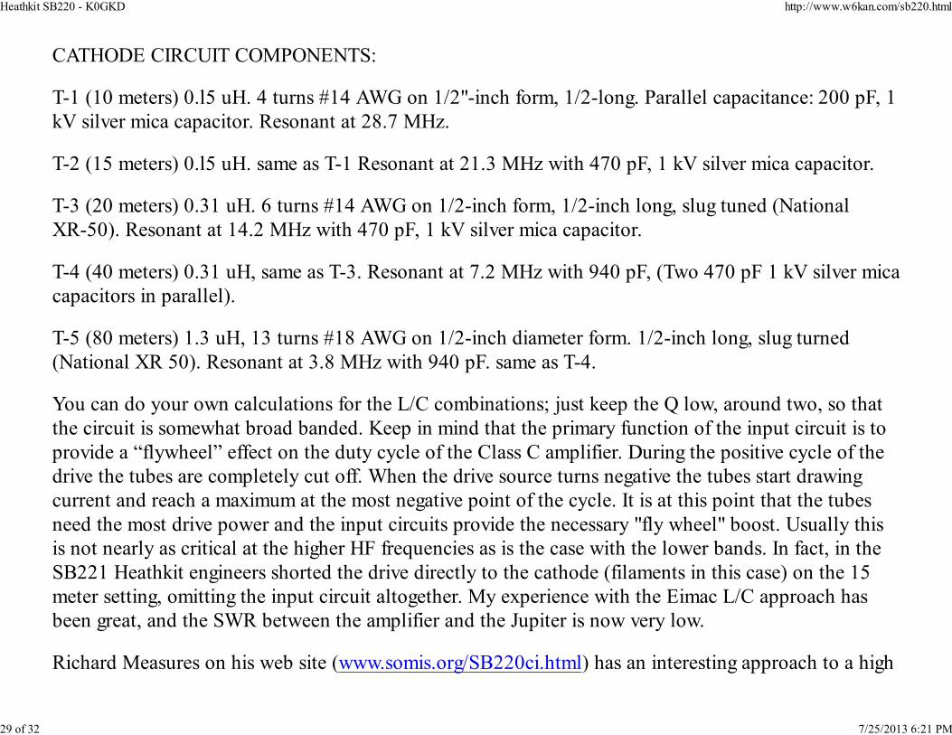
CATHODE CIRCUIT COMPONENTS:
T-1 (10 meters) 0.l5 uH. 4 turns #14 AWG on 1/2"-inch form, 1/2-long. Parallel capacitance: 200 pF, 1
kV silver mica capacitor. Resonant at 28.7 MHz.
T-2 (15 meters) 0.l5 uH. same as T-1 Resonant at 21.3 MHz with 470 pF, 1 kV silver mica capacitor.
T-3 (20 meters) 0.31 uH. 6 turns #14 AWG on 1/2-inch form, 1/2-inch long, slug tuned (National
XR-50). Resonant at 14.2 MHz with 470 pF, 1 kV silver mica capacitor.
T-4 (40 meters) 0.31 uH, same as T-3. Resonant at 7.2 MHz with 940 pF, (Two 470 pF 1 kV silver mica
capacitors in parallel).
T-5 (80 meters) 1.3 uH, 13 turns #18 AWG on 1/2-inch diameter form. 1/2-inch long, slug turned
(National XR 50). Resonant at 3.8 MHz with 940 pF. same as T-4.
You can do your own calculations for the L/C combinations; just keep the Q low, around two, so that
the circuit is somewhat broad banded. Keep in mind that the primary function of the input circuit is to
provide a “flywheel” effect on the duty cycle of the Class C amplifier. During the positive cycle of the
drive the tubes are completely cut off. When the drive source turns negative the tubes start drawing
current and reach a maximum at the most negative point of the cycle. It is at this point that the tubes
need the most drive power and the input circuits provide the necessary "fly wheel" boost. Usually this
is not nearly as critical at the higher HF frequencies as is the case with the lower bands. In fact, in the
SB221 Heathkit engineers shorted the drive directly to the cathode (filaments in this case) on the 15
meter setting, omitting the input circuit altogether. My experience with the Eimac L/C approach has
been great, and the SWR between the amplifier and the Jupiter is now very low.
Richard Measures on his web site (www.somis.org/SB220ci.html) has an interesting approach to a high
Heathkit SB220 - K0GKD http://www.w6kan.com/sb220.html
29 of 32 7/25/2013 6:21 PM
SWR between the driving source and the input to the amplifier. He notes that the input circuit was
designed for tube transmitters and altering the Q to a higher level (more C) will improve the match to
accomodate today's modern solid-state transmitters.
With the unit grounded, and a adequate dummy load hooked to the output of the amplifier (I use a
“Cantenna” Heathkit load resistor), route the coax from the transceiver to the “input’ connector, and
terminate the “output” to the dummy load. Note carefully the markings on the terminals on the back to
make sure you get the input and the output in their respective places. Connect the relay terminal to the
exciter or transceiver as noted in your manual using shielded cable – note: the circuit should be open in
the receive mode. The shield can act as the return path for ground. Plug in the amplifier. Hook up a
microphone to the transceiver with a “push to talk” feature. After double-checking all of the
connections turn on the power of both units. Make sure that the transceiver and amplifier are set to the
same band. The amplifier should show the high voltage in the “HV” setting of around 2,200 to 2,500
VDC, and the plate current should be “0”. Always keep in mind that you are dealing with very high
voltages that can be lethal if touched. Do not try to measure these voltages with a standard volt-ohm
meter. Most off-the-shelf meters are not designed to assess these very high voltages, and you clearly do
not want to expose yourself to possible arcing and other unpleasant experiences. You will also damage
your voltmeter irreparably. The SB220 like most amplifiers has built in voltage meters that tell you the
high voltages across the capacitor bank. (Note: if the voltage on the HK meter is indicating a low value
then it probably is an indication that on of the resistors in the bank - R6,7.8 and 9 - could be off. Any
variation in their value will distort the plate voltage reading).
Make sure the drive level of the transceiver/transmitter is at the lowest power setting and in the CW
mode. Key the transceiver on. The amplifier relay should engage and the plate current should now
indicate about 100 to 120 milliamps. Very slowly increase the drive level until the plate current of the
amplifier starts to rise. Immediately dip the tuning capacitor of the amplifier for minimum current, and
the load capacitor for maximum current. Check the SWR between the amplifier and the transceiver,
Heathkit SB220 - K0GKD http://www.w6kan.com/sb220.html
30 of 32 7/25/2013 6:21 PM
and adjusts the appropriate input circuit if you can. At this stage follow the load up instructions in the
operating manual, which probably suggest you tune to maximum RF output. The amplifier should load
to 700 or so milliamps of plate current. Do not continue with this level of output for an extended
period, as the amplifier will possibly overheat. Note the color of the tubes, as they should start to glow
a pinkish hue. If either tube does not have the same color as its counterpart it may need to be replaced
so that a better match between the two tubes will exist.
Place the transceiver in SSB mode and reduce the mike level to the minimum. Key the microphone and
begin speaking and advancing the mike level or drive until voice peaks move the plate current to
300-400 milliamps. If there are no problems you are set to go. Unplug both the amplifier and your
exciter, and allow the high voltage to dissipate – do not disconnect anything until the “HV” indicates
zero.
In operation you will normally have more than enough drive with a 100-watt exciter to reach full
output. Running the amplifier at a reduced level will extend the life of the tubes for years, and make
very little difference in the output of the unit. It is always a good idea to monitor the power output of
the unit, which we are mandated to do by the FCC. I have been able to get to the full legal limit of
1,500 watts output with what I think are the original tubes. However, I have found that it loads much
better at about 1,100 watts output. This is a lot of power and more than enough to make big waves
wherever you go.
If at any time during the entire process you are not sure that you understand what you are doing get
help from a fellow “ham”. It is a good safety idea to have someone run the tests with you. And always
remember to be aware of the high voltage and follow good safety practices. Safety should be firmly set
in your mind so that you will not become careless. This awareness will allow you to work safely with
confidence.
Now you will have that added punch that will get you a 5/9 plus report, and the bigger thrill to some
Heathkit SB220 - K0GKD http://www.w6kan.com/sb220.html
31 of 32 7/25/2013 6:21 PM

degree of “re-building your own”!
Heathkit SB220 - K0GKD http://www.w6kan.com/sb220.html
32 of 32 7/25/2013 6:21 PM