Embed Size (px)
Citation preview
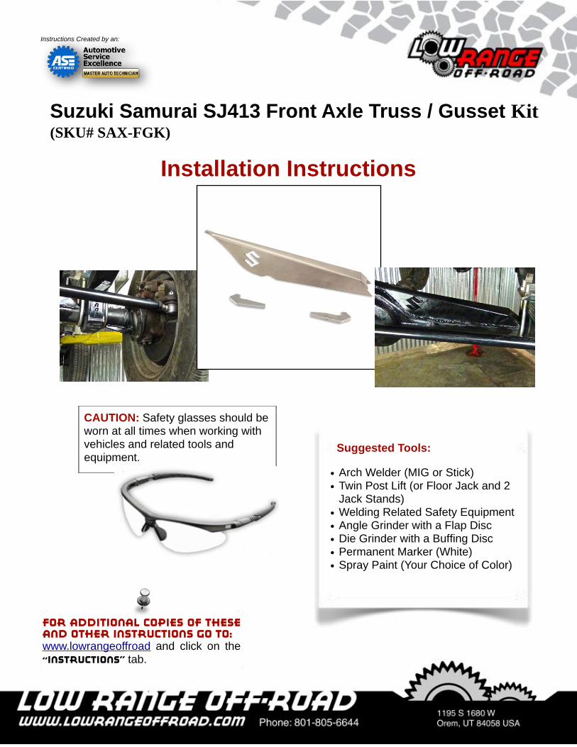
Suggested Tools:
• Arch Welder (MIG or Stick)• Twin Post Lift (or Floor Jack and 2
Jack Stands)• Welding Related Safety Equipment• Angle Grinder with a Flap Disc• Die Grinder with a Buffing Disc• Permanent Marker (White)• Spray Paint (Your Choice of Color)
CAUTION: Safety glasses should be worn at all times when working with vehicles and related tools and equipment.
Suzuki Samurai SJ413 Front Axle Truss / Gusset Kit (SKU# SAX-FGK)
Installation Instructions
For additional copies of these and other instructions go to:www.lowrangeoffroad and click on the “Instructions” tab.
Instructions Created by an:
Lifting and Supporting the Vehicle
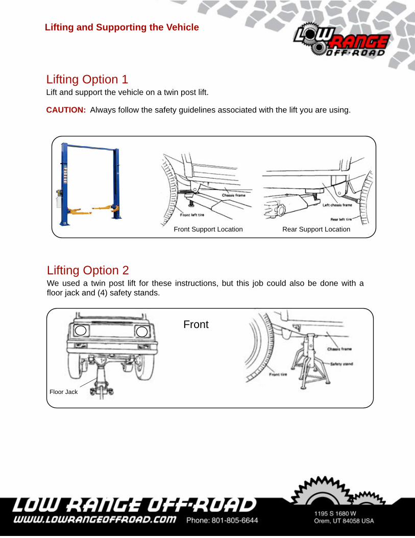
Lifting Option 2We used a twin post lift for these instructions, but this job could also be done with a floor jack and (4) safety stands.
Front
Floor Jack
Lifting Option 1Lift and support the vehicle on a twin post lift.
CAUTION: Always follow the safety guidelines associated with the lift you are using.
Front Support Location Rear Support Location
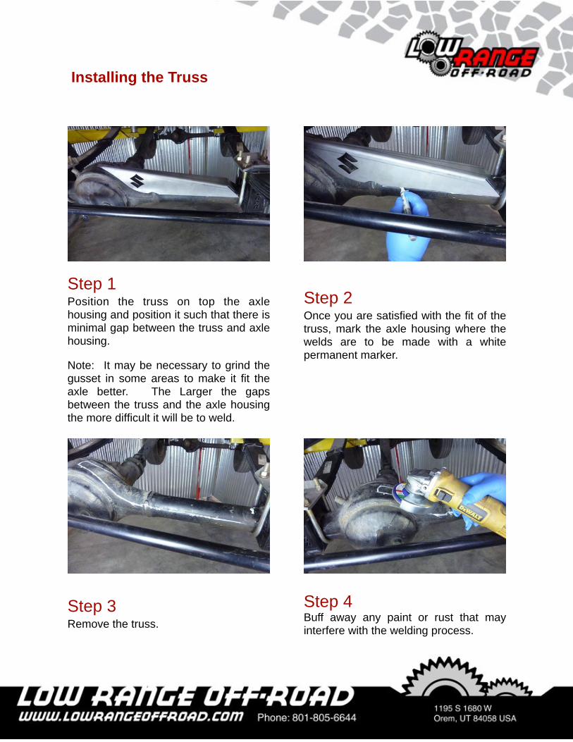
Step 2Once you are satisfied with the fit of the truss, mark the axle housing where the welds are to be made with a white permanent marker.
Step 1Position the truss on top the axle housing and position it such that there is minimal gap between the truss and axle housing.
Note: It may be necessary to grind the gusset in some areas to make it fit the axle better. The Larger the gaps between the truss and the axle housing the more difficult it will be to weld.
Step 3Remove the truss.
Step 4Buff away any paint or rust that may interfere with the welding process.
Installing the Truss
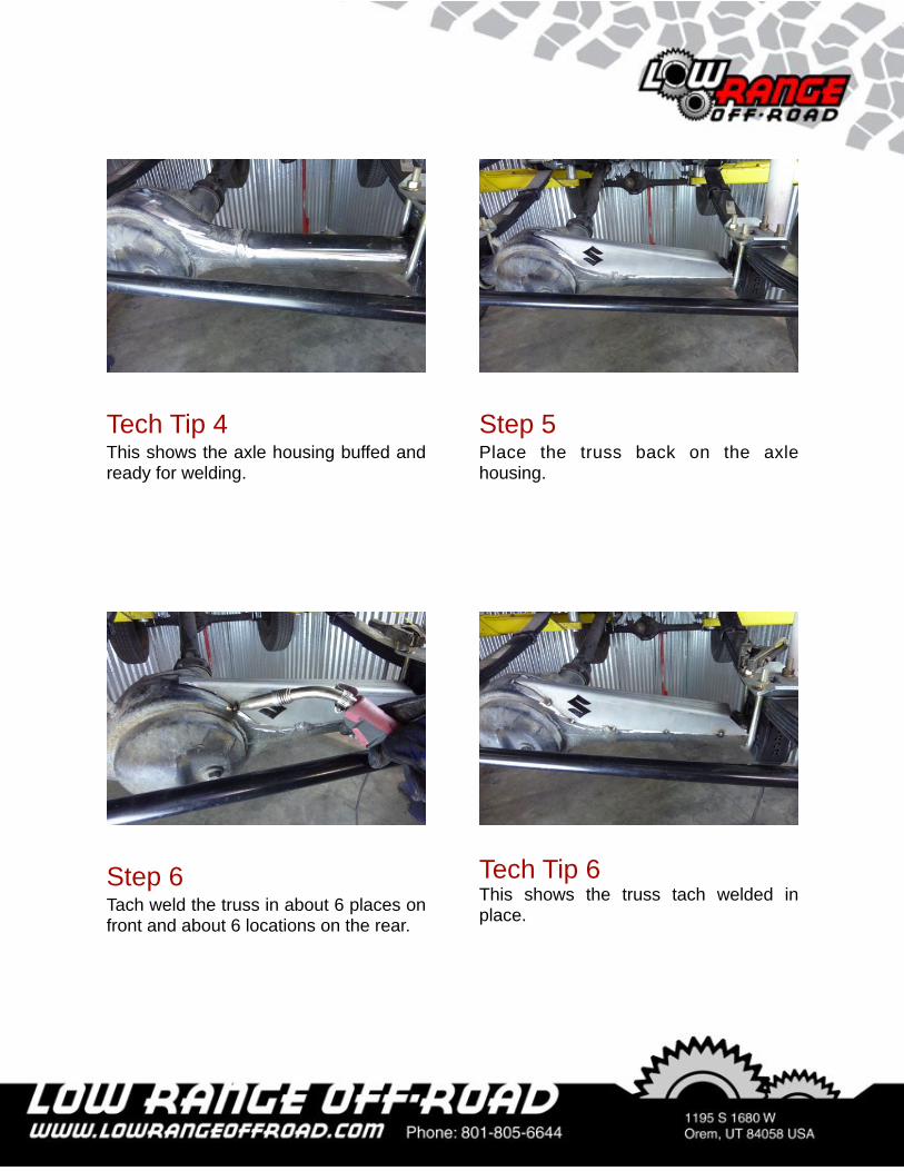
Step 5Place the truss back on the axle housing.
Tech Tip 4This shows the axle housing buffed and ready for welding.
Step 6Tach weld the truss in about 6 places on front and about 6 locations on the rear.
Tech Tip 6This shows the truss tach welded in place.
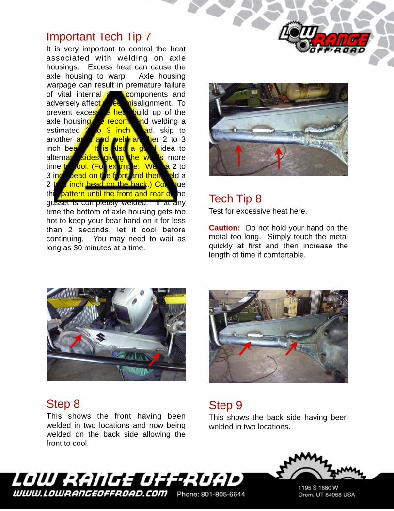
Step 8This shows the front having been welded in two locations and now being welded on the back side allowing the front to cool.
Important Tech Tip 7It is very important to control the heat associated with welding on axle housings. Excess heat can cause the axle housing to warp. Axle housing warpage can result in premature failure of vital internal axle components and adversely affect wheel misalignment. To prevent excessive heat build up of the axle housing we recommend welding a estimated 2 to 3 inch bead, skip to another area and weld another 2 to 3 inch bead. It is also a good idea to alternate sides giving the welds more time to cool. (For example: Weld a 2 to 3 inch bead on the front and then weld a 2 to 3 inch bead on the back.) Continue this pattern until the front and rear of the gusset is completely welded. If at any time the bottom of axle housing gets too hot to keep your bear hand on it for less than 2 seconds, let it cool before continuing. You may need to wait as long as 30 minutes at a time.
Step 9This shows the back side having been welded in two locations.
Tech Tip 8Test for excessive heat here.
Caution: Do not hold your hand on the metal too long. Simply touch the metal quickly at first and then increase the length of time if comfortable.
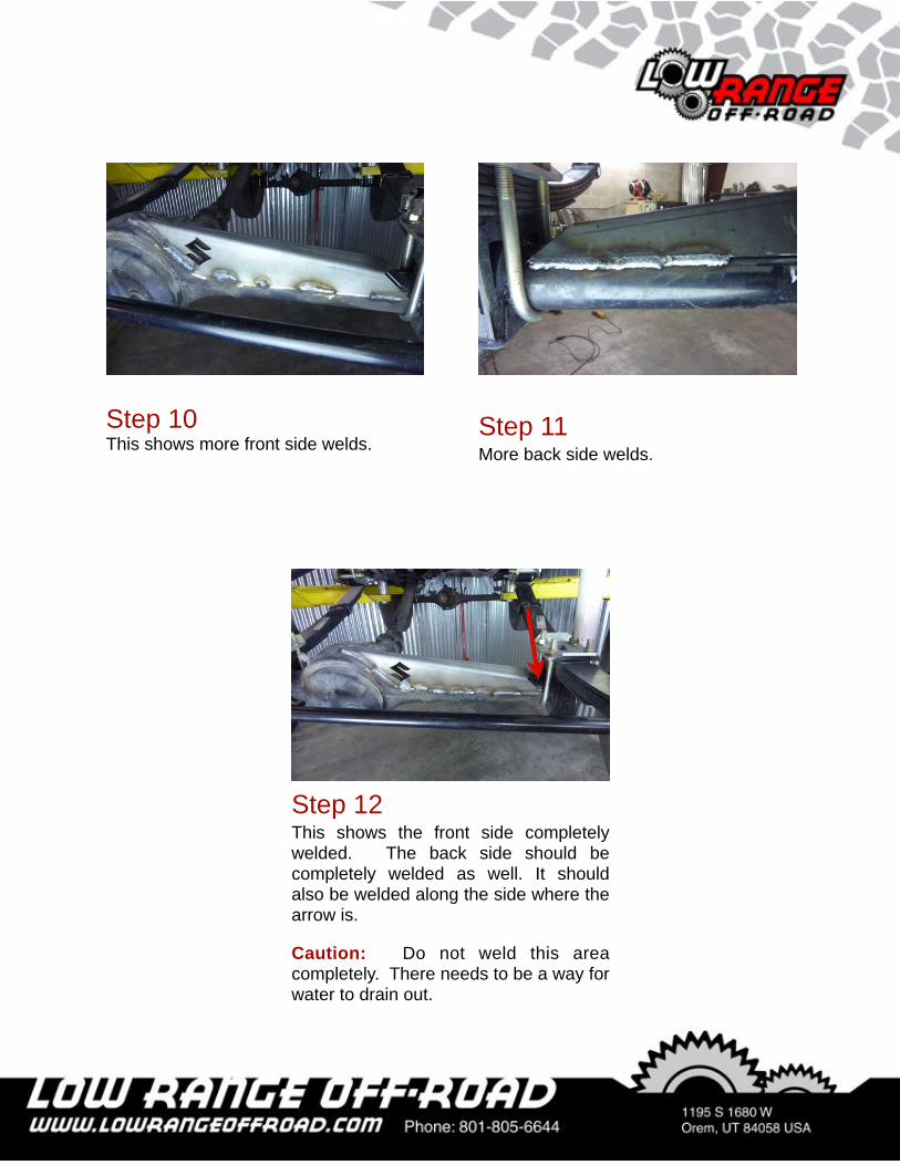
Step 12This shows the front side completely welded. The back side should be completely welded as well. It should also be welded along the side where the arrow is.
Caution: Do not weld this area completely. There needs to be a way for water to drain out.
Step 11More back side welds.
Step 10This shows more front side welds.
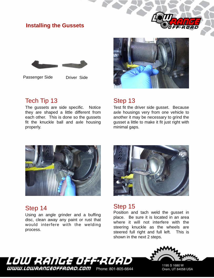
Step 13Test fit the driver side gusset. Because axle housings very from one vehicle to another it may be necessary to grind the gusset a little to make it fit just right with minimal gaps.
Tech Tip 13The gussets are side specific. Notice they are shaped a little different from each other. This is done so the gussets fit the knuckle ball and axle housing properly.
Step 14Using an angle grinder and a buffing disc, clean away any paint or rust that would interfere with the welding process.
Step 15Position and tach weld the gusset in place. Be sure it is located in an area where it will not interfere with the steering knuckle as the wheels are steered full right and full left. This is shown in the next 2 steps.
Installing the Gussets
Passenger Side Driver Side
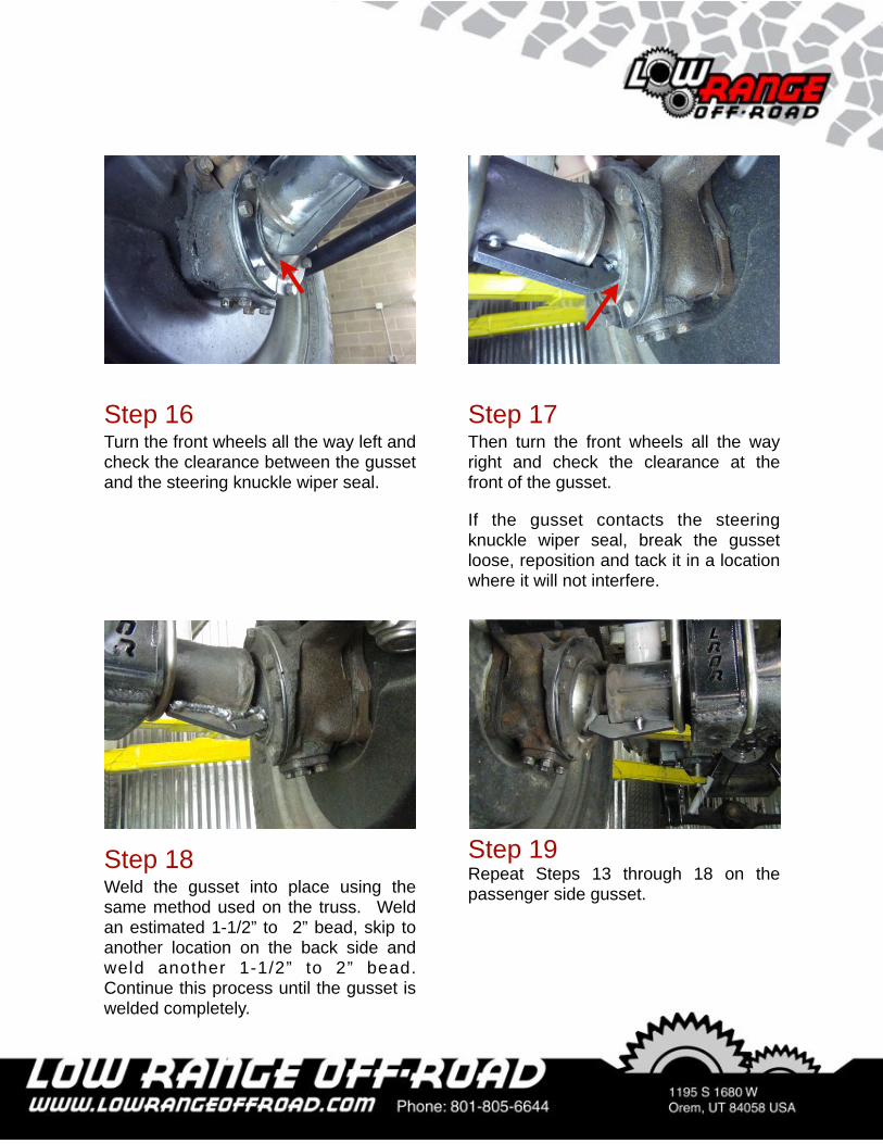
Step 17Then turn the front wheels all the way right and check the clearance at the front of the gusset.
If the gusset contacts the steering knuckle wiper seal, break the gusset loose, reposition and tack it in a location where it will not interfere.
Step 16Turn the front wheels all the way left and check the clearance between the gusset and the steering knuckle wiper seal.
Step 19Repeat Steps 13 through 18 on the passenger side gusset.
Step 18Weld the gusset into place using the same method used on the truss. Weld an estimated 1-1/2” to 2” bead, skip to another location on the back side and weld another 1-1/2” to 2” bead. Continue this process until the gusset is welded completely.
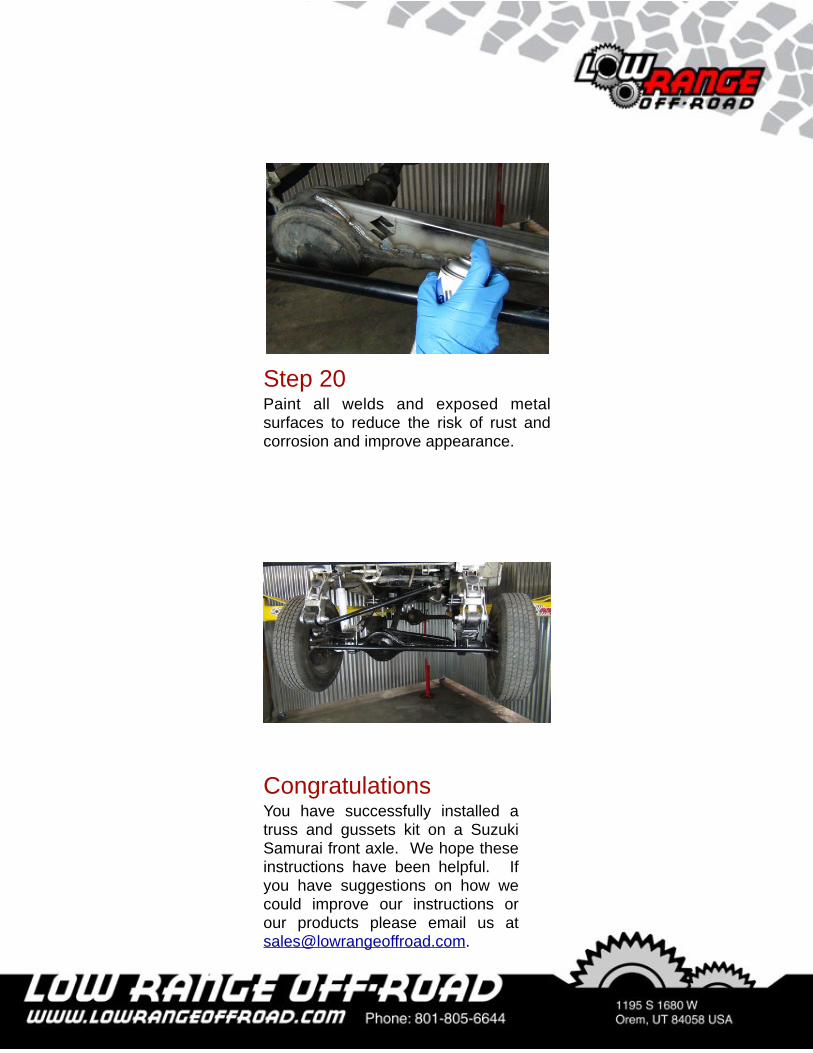
Step 20Paint all welds and exposed metal surfaces to reduce the risk of rust and corrosion and improve appearance.
CongratulationsYou have successfully installed a truss and gussets kit on a Suzuki Samurai front axle. We hope these instructions have been helpful. If you have suggestions on how we could improve our instructions or our products please email us at [email protected].
As always, If you experience any difficulty during the installation of this product please contact Low Range Off-Road Technical Support at 801-805-6644 M-F 7:30am-5:30pm MST. Thank you for purchasing from Low Range Off-Road.
These instructions are designed as a general installation guide. Installation of many Low Range Off-Road products require specialized skills such as metal fabrication, welding and mechanical trouble shooting. If you have any questions or are unsure about how to proceed, please contact our shop at 801-805-6644 or seek help from a competent fabricator. Using fabrication tools such as welders, torches and grinders can cause serious bodily harm and death. Please operate equipment carefully and observe proper safety procedures.
Rock crawling and off-road driving are inherently dangerous activities. Some modifications will adversely affect the on-road handling characteristics of your vehicle. All products sold by Low Range Off-Road are sold for off road use only. Any other use or application is the responsibility of the purchaser and/or user. Some modifications and installation of certain aftermarket parts may under certain circumstances void your original dealer warranty. Modification of your vehicle may create dangerous conditions, which could cause roll-overs resulting in serious bodily injury or death. Buyers and users of these products hereby expressly assume all risks associated with any such modifications and use.
Revised 06/18/14© Copyright 2014 Low Range Off-Road, LC All Rights Reserved