Embed Size (px)
Citation preview

Suggested Tools:
• Dial Indicator• Torque Wrench, dial or needle type (inch-
pound)• Torque Wrench (foot-pound)• Sockets, 12,14,17 mm• Ratchet• Brass Hammer• Spanner Wrench• Bearing Grease
CAUTION: Safety glasses should be worn at all times when working with vehicles and related tools and equipment.
Suzuki Samurai 26 Spline Lockright® Locker w/o Couplers (SKU# SAX-1510)
Installation Instructions
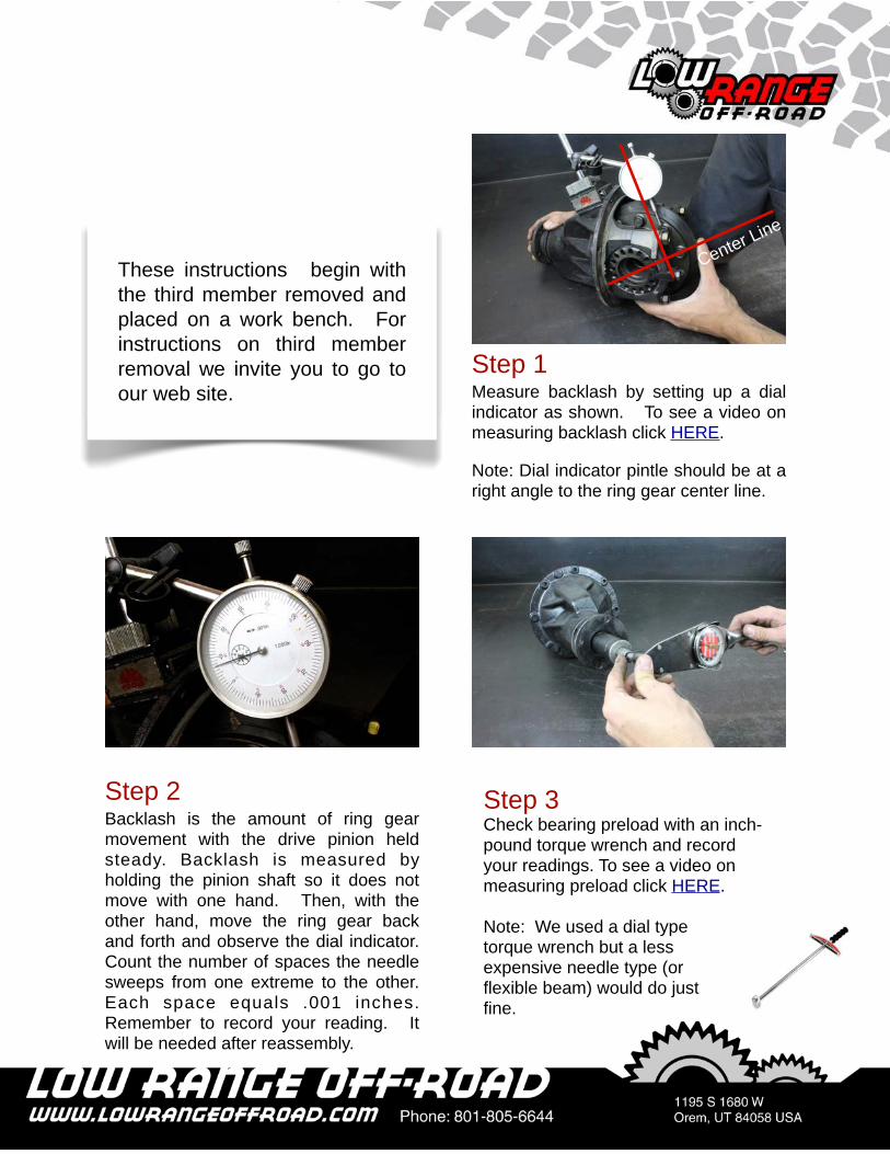
Step 1Measure backlash by setting up a dial indicator as shown. To see a video on measuring backlash click HERE.
Note: Dial indicator pintle should be at a right angle to the ring gear center line.
These instructions begin with the third member removed and placed on a work bench. For instructions on third member removal we invite you to go to our web site.
Step 2Backlash is the amount of ring gear movement with the drive pinion held steady. Backlash is measured by holding the pinion shaft so it does not move with one hand. Then, with the other hand, move the ring gear back and forth and observe the dial indicator. Count the number of spaces the needle sweeps from one extreme to the other. Each space equals .001 inches. Remember to record your reading. It will be needed after reassembly.
Step 3Check bearing preload with an inch-pound torque wrench and record your readings. To see a video on measuring preload click HERE.
Note: We used a dial type torque wrench but a less expensive needle type (or flexible beam) would do just fine.
Center Line

Step 5Mark the left bearing cap so it can be easily distinguish from the right.
Note: Bearing caps must be reinstalled in their original position. We used yellow paint for marking, but any stamp, file or engraver would work.
Step 4Bearing preload is measuring the effort required to turn the differential pinion shaft. To measure preload, place an inch pound torque wrench on the drive pinion nut and rotate the pinion shaft. (See picture in Step 3) While rotating the shaft note the reading on the torque wrench. Be sure to record the reading because you will need to check and adjust the preload near the end of this procedure.
Tech TipAs mentioned, it is critical that you reassemble the differential carrier parts in the same location from which they were removed. Setting them on the workbench as shown works well.
Step 6Remove both (left and right) bearing adjuster lock plates by removing (2) 12 mm bolt.
Left Side Right Side
Left Side
Right Lock Plate

Step 8It may be necessary to tap on the caps with a brass hammer to assist in removal.
Step 7Remove both side bearing caps by removing (4) 17 mm bolts.
Step 9Remove both (left and right) bearing adjusters.
Left Bearing Cap
Right Bearing Cap
Left Bearing Adjuster
Step 10Remove the differential case.
Differential Case
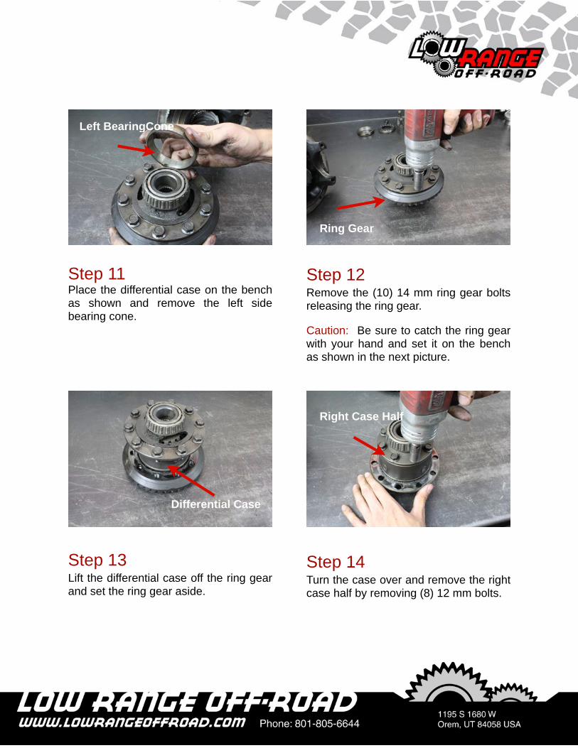
Step 13Lift the differential case off the ring gear and set the ring gear aside.
Step 12Remove the (10) 14 mm ring gear bolts releasing the ring gear.
Caution: Be sure to catch the ring gear with your hand and set it on the bench as shown in the next picture.
Step 14Turn the case over and remove the right case half by removing (8) 12 mm bolts.
Ring Gear
Differential Case
Right Case Half
Step 11Place the differential case on the bench as shown and remove the left side bearing cone.
Left BearingCone
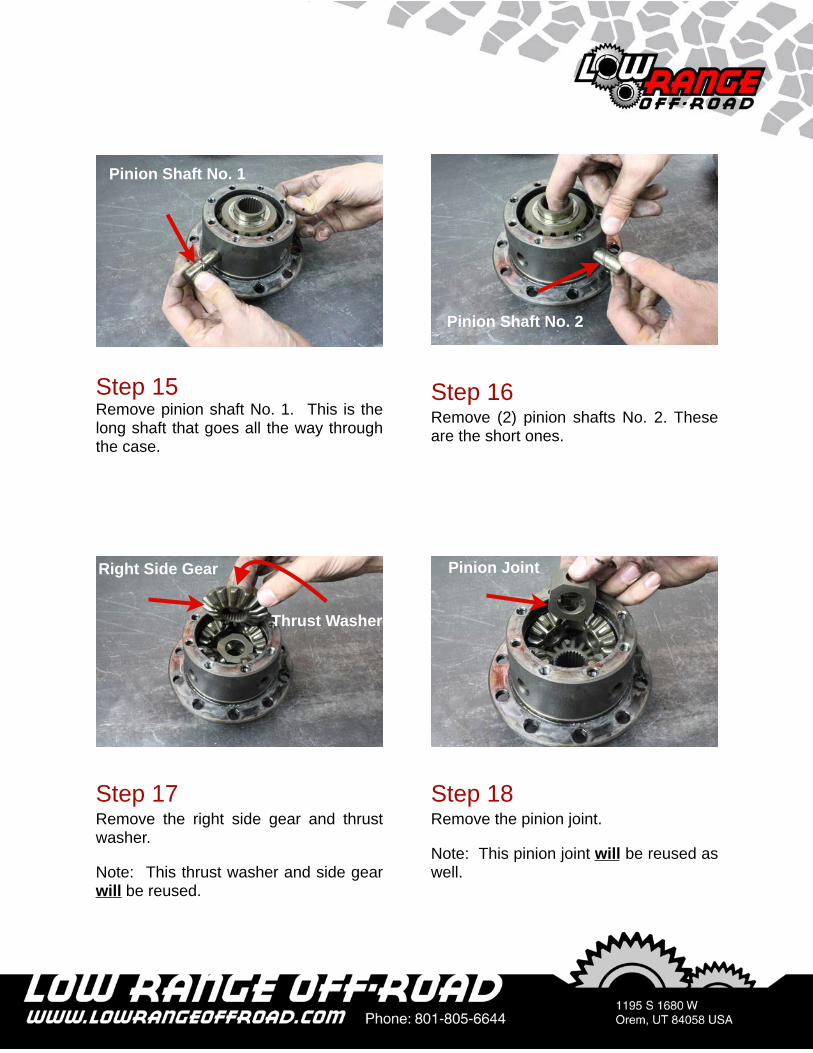
Step 17Remove the right side gear and thrust washer.
Note: This thrust washer and side gear will be reused.
Step 16Remove (2) pinion shafts No. 2. These are the short ones.
Step 18Remove the pinion joint.
Note: This pinion joint will be reused as well.
Pinion Shaft No. 2
Right Side Gear Pinion Joint
Step 15Remove pinion shaft No. 1. This is the long shaft that goes all the way through the case.
Pinion Shaft No. 1
Thrust Washer

Step 20Remove the left side gear and thrust washer.
Note: This side gear and trust washer will be reused as well.
Step 21Apply grease to the original left side gear thrust washer.
Note: The grease serves as “glue” to keep the washer in place during installation.
Lockright® Locker Installation
Thrust Washer
Left Side Gear
Step 19Remove the (4) pinion gears and thrust washers.
Note: The pinion gears and thrust washers will not be reused.
Pinion GearThrust Washer
Step 22Place the original left side gear thrust washer on the original left side gear as shown.

Step 24Apply grease to one pin as shown.
Note: Again, the grease serves as “Glue” to hold the parts in place during reassembly.
Step 23Install the original left side gear in the case as shown.
Note: Be sure the left side gear turns freely.
Step 25Install the pin in the driver as shown.
Note: The pin goes in the round hole not the oblong hole.
Step 26Apply grease to a second pin and install it opposite the first.
Second PinDriver
First Pin

Step 28Put a small spring inside a large spring as shown.
Step 27Apply grease to the remaining two holes.
Step 29Insert the springs in one of the oblong holes.
Step 30Put two more springs together (small and large) and insert them in the last hole.

Step 32Install a spacer.
Step 31Install the driver inside the case as shown.
Step 33Install the pinion block.
Step 34Align the holes in the case with the holes in the driver and pinion block. Then install pinion shaft No. 1 as shown.
Note: Pinion shaft No. 1 is the new long shaft supplied with the Lockright® kit.

Step 36Prepare the second driver by installing the pins and springs as before in Steps 25 through 30.
Note: Don’t forget to use grease to hold the pins and springs in place.
Step 35Install the (2) pinion shafts No. 2 as shown.
Note: Pinion shafts No. 2 are the new short shafts supplied with the Lockright® kit.
Step 37Install the second driver as shown.
Note: Be sure the PINS in the first driver align with the SPRINGS in the second driver.
Step 38Install the second spacer as shown.
PinSpring

Step 40Install the original side gear as shown.
Step 39Place the original side gear thrust washer on the original side gear.
Step 41Install the differential right case.
Step 42Apply Blue Loctite® to the threads of the (8) differential case bolts and install.

Step 43Torque the differential case bolts 27 to 32.5 ft. lbs.
Step 44Posit ion the r ing gear over the differential case.
Step 45Turn the case over, hold the ring gear in place, apply Red Loctite® to the threads and install the bolts.
Step 46Torque the ring gear bolts 58 to 66 ft. lbs.

Step 47Place the (2) side bearing cups on the side bearings.
Note: Be sure the left cup goes on the left bearing and the right cup goes on the right bearing.
Step 48Place the differential case in the carrier as shown.
Step 49Install the right side bearing cap and bolts. Then tighten the bolts 7.5 to 14 ft. lbs. Be sure that this is the RIGHT side bearing cap.
Note: We are only snugging these bolts at this point. We will do the final torque later.
Step 50Install the LEFT side bearing cap and bolts and tighten 7.5 to 14 ft. lbs.
Note: Notice the mark indicating it is the left side bearing cap.
Left Cup and Bearing

Step 51Install both left and right bearing adjusters.
Note: Again, be sure the adjusters are placed on the correct sides.
Left Bearing Adjuster
Step 52Snug the bearing adjusters such that the case and ring gear turns easily but does not move side to side.
Note: There is no spec for this but we estimate 15 to 20 ft. lbs. of torque on the adjuster.
Right Adjuster
Clockwise
Step 53Check backlash with a dial indicator as shown. (Click HERE to see Backlash video) Backlash should be set to what it was before disassembly in Step 1. If you need to increase backlash, turn the left adjuster counter-clockwise and the right adjuster clockwise an equal amount. To decrease backlash, turn the right adjuster counter-clockwise and the left adjuster clockwise and equal amount.
Note: One notch changes the backlash by about .002 in.
Left Adjuster
Clockwise
Backlash Adjustment Procedure
Notch

Step 54Check bearing preload as shown. (Click HERE to see Preload video) The preload should be what it was before disassembly. If preload is what it was at the beginning, the preload adjustment is complete. You may skip to Step 57. If preload is not correct continue to the
Step 55To increase preload, turn the left adjuster clockwise and turn the right adjuster an equal amount clockwise.
To decrease preload, turn the left adjuster counter-clockwise and turn the right adjuster an equal amount counter-clockwise.
Preload Adjustment Procedure
Step 57Install the the bearing lock plates and tighten bolts 7 to 10 ft. lbs.
Note: It may be necessary to rotate the adjuster slightly to align the holes in the adjuster with the pin in the lock plate.
Step 56Recheck preload. If preload is within specification, recheck backlash to insure it is still within specification. If backlash is NOT within specification you will need to repeat the backlash procedure, as well as repeat the preload procedure, until both are as close as possible to the original settings.

Step 58Finish tightening the (4) bearing cap bolts 51 to 72 ft. lbs.
This marks the end of the Powertrax Lockright® Locker installation. For third member installation instructions we invite you to go to our web site. Thanks for letting us help you with this procedure! We hope you enjoy your new locker!

As always, If you experience any difficulty during the installation of this product please contact Low Range Off-Road Technical Support at 801-805-6644 M-F 8am-5pm MST. Thank you for purchasing from Low Range Off-Road.
These instructions are designed as a general installation guide. Installation of many Low Range Off-Road require specialized skills such as metal fabrication, welding and mechanical trouble shooting. If you have any questions or are unsure about how to proceed, please contact our shop at 801-805-6644 or seek help from a competent fabricator. Using fabrication tools such as welders, torches and grinders can cause serious bodily harm and death. Please operate equipment carefully and observe proper safety procedures.
Rock crawling and off-road driving are inherently dangerous activities. Some modifications will adversely affect the on-road handling characteristics of your vehicle. All products sold by Low Range Off-Road are sold for off road use only. Any other use or application is the responsibility of the purchaser and/or user. Some modifications and installation of certain aftermarket parts may under certain circumstances void your original dealer warranty. Modification of your vehicle may create dangerous conditions, which could cause roll-overs resulting in serious bodily injury or death. Buyers and users of these products hereby expressly assume all risks associated with any such modifications and use.
Revised 07/31/12 © Copyright 2012 Low Range Off-Road, LC All Rights Reserved