Embed Size (px)
Citation preview
Product Manual
Savvio® 15K.2 SAS
100516230Rev. DSeptember 2010
Standard Models
ST9146852SSST973452SS
Self-Encrypting Drive Models ST9146752SSST973352SS
SED FIPS 140-2 Models ST9146652SSST973252SS
© 2010, Seagate Technology LLC All rights reserved. Publication number: 100516230, Rev. D September 2010
Seagate, Seagate Technology and the Wave logo are registered trademarks of Seagate Technology LLC in the United States and/or other countries. Savvio and SeaTools are either trademarks or reg-istered trademarks of Seagate Technology LLC or one of its affiliated companies in the United States and/or other countries. All other trademarks or registered trademarks are the property of their respective owners.No part of this publication may be reproduced in any form without written permission of Seagate Technology LLC. Call 877-PUB-TEK1(877-782-8651) to request permission.One gigabyte, or GB, equals one billion bytes and one terabyte, or TB, equals one trillion bytes. Your computer's operating system may use a different standard of measurement and report a lower capacity. In addition, some of the listed capacity is used for formatting and other functions, and thus will not be available for data storage. Seagate reserves the right to change, without notice, product offerings or specifications.
Savvio 15K.2 SAS Product Manual, Rev. D i
Contents1.0 Seagate Technology support services. . . . . . . . . . . . . . . . . . . . . . . . . . . . . . . . . . . . . . . . . . . . . 12.0 Scope. . . . . . . . . . . . . . . . . . . . . . . . . . . . . . . . . . . . . . . . . . . . . . . . . . . . . . . . . . . . . . . . . . . . . . . . 23.0 Applicable standards and reference documentation . . . . . . . . . . . . . . . . . . . . . . . . . . . . . . . . . 3
3.1 Standards . . . . . . . . . . . . . . . . . . . . . . . . . . . . . . . . . . . . . . . . . . . . . . . . . . . . . . . . . . . . . . 33.1.1 Electromagnetic compatibility. . . . . . . . . . . . . . . . . . . . . . . . . . . . . . . . . . . . . . . . 33.1.2 Electromagnetic compliance . . . . . . . . . . . . . . . . . . . . . . . . . . . . . . . . . . . . . . . . 43.1.3 European Union Restriction of Hazardous Substances (RoHS) . . . . . . . . . . . . . 5
3.2 Reference documents . . . . . . . . . . . . . . . . . . . . . . . . . . . . . . . . . . . . . . . . . . . . . . . . . . . . . 5
4.0 General description . . . . . . . . . . . . . . . . . . . . . . . . . . . . . . . . . . . . . . . . . . . . . . . . . . . . . . . . . . . . 64.1 Standard features . . . . . . . . . . . . . . . . . . . . . . . . . . . . . . . . . . . . . . . . . . . . . . . . . . . . . . . . 74.2 Media description . . . . . . . . . . . . . . . . . . . . . . . . . . . . . . . . . . . . . . . . . . . . . . . . . . . . . . . . 74.3 Performance . . . . . . . . . . . . . . . . . . . . . . . . . . . . . . . . . . . . . . . . . . . . . . . . . . . . . . . . . . . . 84.4 Reliability . . . . . . . . . . . . . . . . . . . . . . . . . . . . . . . . . . . . . . . . . . . . . . . . . . . . . . . . . . . . . . . 84.5 Formatted capacities . . . . . . . . . . . . . . . . . . . . . . . . . . . . . . . . . . . . . . . . . . . . . . . . . . . . . . 84.6 Programmable drive capacity . . . . . . . . . . . . . . . . . . . . . . . . . . . . . . . . . . . . . . . . . . . . . . . 94.7 Options . . . . . . . . . . . . . . . . . . . . . . . . . . . . . . . . . . . . . . . . . . . . . . . . . . . . . . . . . . . . . . . . 9
5.0 Performance characteristics . . . . . . . . . . . . . . . . . . . . . . . . . . . . . . . . . . . . . . . . . . . . . . . . . . . . 105.1 Internal drive characteristics . . . . . . . . . . . . . . . . . . . . . . . . . . . . . . . . . . . . . . . . . . . . . . . 105.2 Seek performance characteristics . . . . . . . . . . . . . . . . . . . . . . . . . . . . . . . . . . . . . . . . . . . 10
5.2.1 Access time . . . . . . . . . . . . . . . . . . . . . . . . . . . . . . . . . . . . . . . . . . . . . . . . . . . . 105.2.2 Format command execution time . . . . . . . . . . . . . . . . . . . . . . . . . . . . . . . . . . . 115.2.3 General performance characteristics . . . . . . . . . . . . . . . . . . . . . . . . . . . . . . . . . 11
5.3 Start/stop time . . . . . . . . . . . . . . . . . . . . . . . . . . . . . . . . . . . . . . . . . . . . . . . . . . . . . . . . . . 115.4 Prefetch/multi-segmented cache control . . . . . . . . . . . . . . . . . . . . . . . . . . . . . . . . . . . . . . 125.5 Cache operation . . . . . . . . . . . . . . . . . . . . . . . . . . . . . . . . . . . . . . . . . . . . . . . . . . . . . . . . 12
5.5.1 Caching write data . . . . . . . . . . . . . . . . . . . . . . . . . . . . . . . . . . . . . . . . . . . . . . . 135.5.2 Prefetch operation . . . . . . . . . . . . . . . . . . . . . . . . . . . . . . . . . . . . . . . . . . . . . . . 13
6.0 Reliability specifications . . . . . . . . . . . . . . . . . . . . . . . . . . . . . . . . . . . . . . . . . . . . . . . . . . . . . . . 146.1 Error rates . . . . . . . . . . . . . . . . . . . . . . . . . . . . . . . . . . . . . . . . . . . . . . . . . . . . . . . . . . . . . 14
6.1.1 Recoverable Errors . . . . . . . . . . . . . . . . . . . . . . . . . . . . . . . . . . . . . . . . . . . . . . 146.1.2 Unrecoverable Errors . . . . . . . . . . . . . . . . . . . . . . . . . . . . . . . . . . . . . . . . . . . . . 146.1.3 Seek errors. . . . . . . . . . . . . . . . . . . . . . . . . . . . . . . . . . . . . . . . . . . . . . . . . . . . . 156.1.4 Interface errors. . . . . . . . . . . . . . . . . . . . . . . . . . . . . . . . . . . . . . . . . . . . . . . . . . 15
6.2 Reliability and service . . . . . . . . . . . . . . . . . . . . . . . . . . . . . . . . . . . . . . . . . . . . . . . . . . . . 156.2.1 Annualized Failure Rate (AFR) and Mean Time Between Failure (MTBF) . . . . 156.2.2 Preventive maintenance. . . . . . . . . . . . . . . . . . . . . . . . . . . . . . . . . . . . . . . . . . . 156.2.3 Hot plugging the drive . . . . . . . . . . . . . . . . . . . . . . . . . . . . . . . . . . . . . . . . . . . . 156.2.4 S.M.A.R.T. . . . . . . . . . . . . . . . . . . . . . . . . . . . . . . . . . . . . . . . . . . . . . . . . . . . . . 166.2.5 Thermal monitor . . . . . . . . . . . . . . . . . . . . . . . . . . . . . . . . . . . . . . . . . . . . . . . . . 176.2.6 Drive Self Test (DST) . . . . . . . . . . . . . . . . . . . . . . . . . . . . . . . . . . . . . . . . . . . . . 186.2.7 Product warranty . . . . . . . . . . . . . . . . . . . . . . . . . . . . . . . . . . . . . . . . . . . . . . . . 20
7.0 Physical/electrical specifications . . . . . . . . . . . . . . . . . . . . . . . . . . . . . . . . . . . . . . . . . . . . . . . . 217.1 AC power requirements . . . . . . . . . . . . . . . . . . . . . . . . . . . . . . . . . . . . . . . . . . . . . . . . . . . 217.2 DC power requirements. . . . . . . . . . . . . . . . . . . . . . . . . . . . . . . . . . . . . . . . . . . . . . . . . . . 21
7.2.1 Conducted noise immunity. . . . . . . . . . . . . . . . . . . . . . . . . . . . . . . . . . . . . . . . . 247.2.2 Power sequencing . . . . . . . . . . . . . . . . . . . . . . . . . . . . . . . . . . . . . . . . . . . . . . . 247.2.3 Current profiles. . . . . . . . . . . . . . . . . . . . . . . . . . . . . . . . . . . . . . . . . . . . . . . . . . 25
7.3 Power dissipation . . . . . . . . . . . . . . . . . . . . . . . . . . . . . . . . . . . . . . . . . . . . . . . . . . . . . . . 277.4 Environmental limits . . . . . . . . . . . . . . . . . . . . . . . . . . . . . . . . . . . . . . . . . . . . . . . . . . . . . 29
7.4.1 Temperature. . . . . . . . . . . . . . . . . . . . . . . . . . . . . . . . . . . . . . . . . . . . . . . . . . . . 29
ii Savvio 15K.2 SAS Product Manual, Rev. D
7.4.2 Relative humidity . . . . . . . . . . . . . . . . . . . . . . . . . . . . . . . . . . . . . . . . . . . . . . . . 297.4.3 Effective altitude (sea level) . . . . . . . . . . . . . . . . . . . . . . . . . . . . . . . . . . . . . . . . 307.4.4 Shock and vibration . . . . . . . . . . . . . . . . . . . . . . . . . . . . . . . . . . . . . . . . . . . . . . 307.4.5 Air cleanliness . . . . . . . . . . . . . . . . . . . . . . . . . . . . . . . . . . . . . . . . . . . . . . . . . . 327.4.6 Corrosive environment . . . . . . . . . . . . . . . . . . . . . . . . . . . . . . . . . . . . . . . . . . . . 327.4.7 Acoustics . . . . . . . . . . . . . . . . . . . . . . . . . . . . . . . . . . . . . . . . . . . . . . . . . . . . . . 337.4.8 Electromagnetic susceptibility . . . . . . . . . . . . . . . . . . . . . . . . . . . . . . . . . . . . . . 33
7.5 Mechanical specifications . . . . . . . . . . . . . . . . . . . . . . . . . . . . . . . . . . . . . . . . . . . . . . . . . 34
8.0 About FIPS. . . . . . . . . . . . . . . . . . . . . . . . . . . . . . . . . . . . . . . . . . . . . . . . . . . . . . . . . . . . . . . . . . . 359.0 About self-encrypting drives . . . . . . . . . . . . . . . . . . . . . . . . . . . . . . . . . . . . . . . . . . . . . . . . . . . . 36
9.1 Data encryption . . . . . . . . . . . . . . . . . . . . . . . . . . . . . . . . . . . . . . . . . . . . . . . . . . . . . . . . . 369.2 Controlled access. . . . . . . . . . . . . . . . . . . . . . . . . . . . . . . . . . . . . . . . . . . . . . . . . . . . . . . . 36
9.2.1 Admin SP . . . . . . . . . . . . . . . . . . . . . . . . . . . . . . . . . . . . . . . . . . . . . . . . . . . . . . 369.2.2 Locking SP . . . . . . . . . . . . . . . . . . . . . . . . . . . . . . . . . . . . . . . . . . . . . . . . . . . . . 379.2.3 Default password . . . . . . . . . . . . . . . . . . . . . . . . . . . . . . . . . . . . . . . . . . . . . . . . 37
9.3 Random number generator (RNG). . . . . . . . . . . . . . . . . . . . . . . . . . . . . . . . . . . . . . . . . . . 379.4 Drive locking. . . . . . . . . . . . . . . . . . . . . . . . . . . . . . . . . . . . . . . . . . . . . . . . . . . . . . . . . . . . 379.5 Data bands. . . . . . . . . . . . . . . . . . . . . . . . . . . . . . . . . . . . . . . . . . . . . . . . . . . . . . . . . . . . . 379.6 Cryptographic erase. . . . . . . . . . . . . . . . . . . . . . . . . . . . . . . . . . . . . . . . . . . . . . . . . . . . . . 389.7 Authenticated firmware download . . . . . . . . . . . . . . . . . . . . . . . . . . . . . . . . . . . . . . . . . . . 389.8 Power requirements . . . . . . . . . . . . . . . . . . . . . . . . . . . . . . . . . . . . . . . . . . . . . . . . . . . . . . 389.9 Supported commands . . . . . . . . . . . . . . . . . . . . . . . . . . . . . . . . . . . . . . . . . . . . . . . . . . . . 38
10.0 Defect and error management . . . . . . . . . . . . . . . . . . . . . . . . . . . . . . . . . . . . . . . . . . . . . . . . . . . 3910.1 Drive internal defects/errors . . . . . . . . . . . . . . . . . . . . . . . . . . . . . . . . . . . . . . . . . . . . . . . . 3910.2 Drive error recovery procedures . . . . . . . . . . . . . . . . . . . . . . . . . . . . . . . . . . . . . . . . . . . . 3910.3 SAS system errors . . . . . . . . . . . . . . . . . . . . . . . . . . . . . . . . . . . . . . . . . . . . . . . . . . . . . . . 4010.4 Background Media Scan . . . . . . . . . . . . . . . . . . . . . . . . . . . . . . . . . . . . . . . . . . . . . . . . . . 4110.5 Media Pre-Scan . . . . . . . . . . . . . . . . . . . . . . . . . . . . . . . . . . . . . . . . . . . . . . . . . . . . . . . . . 4110.6 Deferred Auto-Reallocation . . . . . . . . . . . . . . . . . . . . . . . . . . . . . . . . . . . . . . . . . . . . . . . . 4110.7 Idle Read After Write . . . . . . . . . . . . . . . . . . . . . . . . . . . . . . . . . . . . . . . . . . . . . . . . . . . . . 42
11.0 Installation . . . . . . . . . . . . . . . . . . . . . . . . . . . . . . . . . . . . . . . . . . . . . . . . . . . . . . . . . . . . . . . . . . . 4311.1 Drive orientation . . . . . . . . . . . . . . . . . . . . . . . . . . . . . . . . . . . . . . . . . . . . . . . . . . . . . . . . . 4311.2 Cooling . . . . . . . . . . . . . . . . . . . . . . . . . . . . . . . . . . . . . . . . . . . . . . . . . . . . . . . . . . . . . . . . 4411.3 Drive mounting . . . . . . . . . . . . . . . . . . . . . . . . . . . . . . . . . . . . . . . . . . . . . . . . . . . . . . . . . . 4511.4 Grounding . . . . . . . . . . . . . . . . . . . . . . . . . . . . . . . . . . . . . . . . . . . . . . . . . . . . . . . . . . . . . 45
12.0 Interface requirements . . . . . . . . . . . . . . . . . . . . . . . . . . . . . . . . . . . . . . . . . . . . . . . . . . . . . . . . . 4612.1 SAS features . . . . . . . . . . . . . . . . . . . . . . . . . . . . . . . . . . . . . . . . . . . . . . . . . . . . . . . . . . . 46
12.1.1 Task management functions . . . . . . . . . . . . . . . . . . . . . . . . . . . . . . . . . . . . . . . 4612.1.2 Task management responses . . . . . . . . . . . . . . . . . . . . . . . . . . . . . . . . . . . . . . 46
12.2 Dual port support . . . . . . . . . . . . . . . . . . . . . . . . . . . . . . . . . . . . . . . . . . . . . . . . . . . . . . . . 4712.3 SCSI commands supported . . . . . . . . . . . . . . . . . . . . . . . . . . . . . . . . . . . . . . . . . . . . . . . . 48
12.3.1 Inquiry data. . . . . . . . . . . . . . . . . . . . . . . . . . . . . . . . . . . . . . . . . . . . . . . . . . . . . 5212.3.2 Mode Sense data . . . . . . . . . . . . . . . . . . . . . . . . . . . . . . . . . . . . . . . . . . . . . . . . 52
12.4 Miscellaneous operating features and conditions . . . . . . . . . . . . . . . . . . . . . . . . . . . . . . . 5612.4.1 SAS physical interface . . . . . . . . . . . . . . . . . . . . . . . . . . . . . . . . . . . . . . . . . . . . 5712.4.2 Physical characteristics . . . . . . . . . . . . . . . . . . . . . . . . . . . . . . . . . . . . . . . . . . . 6012.4.3 Connector requirements . . . . . . . . . . . . . . . . . . . . . . . . . . . . . . . . . . . . . . . . . . . 6012.4.4 Electrical description. . . . . . . . . . . . . . . . . . . . . . . . . . . . . . . . . . . . . . . . . . . . . . 6012.4.5 Pin descriptions . . . . . . . . . . . . . . . . . . . . . . . . . . . . . . . . . . . . . . . . . . . . . . . . . 6012.4.6 SAS transmitters and receivers . . . . . . . . . . . . . . . . . . . . . . . . . . . . . . . . . . . . . 6112.4.7 Power . . . . . . . . . . . . . . . . . . . . . . . . . . . . . . . . . . . . . . . . . . . . . . . . . . . . . . . . . 62
12.5 Signal characteristics . . . . . . . . . . . . . . . . . . . . . . . . . . . . . . . . . . . . . . . . . . . . . . . . . . . . . 62
Savvio 15K.2 SAS Product Manual, Rev. D iii
12.5.1 Ready LED Out . . . . . . . . . . . . . . . . . . . . . . . . . . . . . . . . . . . . . . . . . . . . . . . . . 6212.5.2 Differential signals . . . . . . . . . . . . . . . . . . . . . . . . . . . . . . . . . . . . . . . . . . . . . . . 62
12.6 SAS-2 Specification compliance . . . . . . . . . . . . . . . . . . . . . . . . . . . . . . . . . . . . . . . . . . . . 6312.7 Additional information . . . . . . . . . . . . . . . . . . . . . . . . . . . . . . . . . . . . . . . . . . . . . . . . . . . . 63
iv Savvio 15K.2 SAS Product Manual, Rev. D
Savvio 15K.2 SAS Product Manual, Rev. D 1
List of Figures
Figure 1. Current profile for 146GB models. . . . . . . . . . . . . . . . . . . . . . . . . . . . . . . . . . . . . . . . . . . . . . 25Figure 2. Current profile for 73GB models . . . . . . . . . . . . . . . . . . . . . . . . . . . . . . . . . . . . . . . . . . . . . . . 26Figure 3. 146GB models (6.0 Gbit) DC current and power vs. input/output operations per second . . . 27Figure 4. 146GB models (3.0 Gbit) DC current and power vs. input/output operations per second . . . 27Figure 5. 73GB models (6.0 Gbit) DC current and power vs. input/output operations per second . . . . 28Figure 6. 73GB models (3.0 Gbit) DC current and power vs. input/output operations per second . . . . 28Figure 7. Location of the HDA temperature check point . . . . . . . . . . . . . . . . . . . . . . . . . . . . . . . . . . . . 29Figure 8. Recommended mounting . . . . . . . . . . . . . . . . . . . . . . . . . . . . . . . . . . . . . . . . . . . . . . . . . . . . 31Figure 9. Dimensions . . . . . . . . . . . . . . . . . . . . . . . . . . . . . . . . . . . . . . . . . . . . . . . . . . . . . . . . . . . . . . . 34Figure 10. Example of FIPS tamper evidence labels. . . . . . . . . . . . . . . . . . . . . . . . . . . . . . . . . . . . . . . . 35Figure 11. Physical interface . . . . . . . . . . . . . . . . . . . . . . . . . . . . . . . . . . . . . . . . . . . . . . . . . . . . . . . . . . 43Figure 12. Air flow . . . . . . . . . . . . . . . . . . . . . . . . . . . . . . . . . . . . . . . . . . . . . . . . . . . . . . . . . . . . . . . . . . 44Figure 13. Physical interface. . . . . . . . . . . . . . . . . . . . . . . . . . . . . . . . . . . . . . . . . . . . . . . . . . . . . . . . . . 57Figure 14. SAS device plug dimensions . . . . . . . . . . . . . . . . . . . . . . . . . . . . . . . . . . . . . . . . . . . . . . . . . 58Figure 15. SAS device plug dimensions (detail) . . . . . . . . . . . . . . . . . . . . . . . . . . . . . . . . . . . . . . . . . . . 59Figure 16. SAS transmitters and receivers . . . . . . . . . . . . . . . . . . . . . . . . . . . . . . . . . . . . . . . . . . . . . . . 61

Savvio 15K.2 SAS Product Manual, Rev. D 1
1.0 Seagate Technology support services
SEAGATE ONLINE SUPPORT and SERVICES
For information regarding products and services, visit http://www.seagate.com/www/en-us/about/contact_us/
Available services include:
Presales & Technical support Global Support Services telephone numbers & business hours Authorized Service Centers
For information regarding Warranty Support, visit http://www.seagate.com/www/en-us/support/warranty_&_returns_assistance
For information regarding Data Recovery Services, visit http://www.i365.com
For Seagate OEM & Distribution partner portal, visit https://direct.seagate.com/portal/system
For Seagate reseller portal, visit http://spp.seagate.com
2 Savvio 15K.2 SAS Product Manual, Rev. D
2.0 Scope
This manual describes Seagate Technology® LLC, Savvio® 15K.2 SAS (Serial Attached SCSI) disc drives.
Savvio drives support the SAS Protocol specifications to the extent described in this manual. The SAS Inter-face Manual (part number 100293071) describes the general SAS characteristics of this and other Seagate SAS drives. The Self-Encrypting Drive Reference Manual, part number 100515636, describes the interface, general operation, and security features available on Self-Encrypting Drive models.
Note. Previous generations of Seagate Self-Encrypting Drive models were called Full Disk Encryption (FDE) models before a differentiation between drive-based encryption and other forms of encryp-tion was necessary.
Product data communicated in this manual is specific only to the model numbers listed in this manual. The data listed in this manual may not be predictive of future generation specifications or requirements. If you are designing a system which will use one of the models listed or future generation products and need further assistance, please contact your Field Applications Engineer (FAE) or our global support services group as shown in Section 1.0.
Unless otherwise stated, the information in this manual applies to standard and Self-Encrypting Drive models.
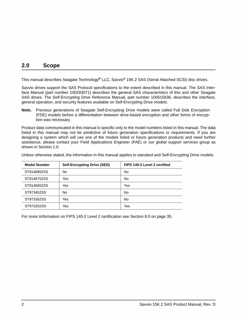
For more iinformation on FIPS 140-2 Level 2 certification see Section 8.0 on page 35.
Model Number Self-Encrypting Drive (SED) FIPS 140-2 Level 2 certified
ST9146852SS No No
ST9146752SS Yes No
ST9146652SS Yes Yes
ST973452SS No No
ST973352SS Yes No
ST973252SS Yes Yes
Savvio 15K.2 SAS Product Manual, Rev. D 3
3.0 Applicable standards and reference documentation
The drives documented in this manual have been developed as system peripherals to the highest standards of design and construction. The drives depends on host equipment to provide adequate power and environment for optimum performance and compliance with applicable industry and governmental regulations. Special attention must be given in the areas of safety, power distribution, shielding, audible noise control, and temper-ature regulation. In particular, the drive must be securely mounted to guarantee the specified performance characteristics. Mounting by bottom holes must meet the requirements of Section 11.3
3.1 Standards
The Savvio family complies with Seagate standards as noted in the appropriate sections of this manual and the Seagate SAS Interface Manual, part number 100293071.
The drives are recognized in accordance with UL 60950-1 as tested by UL, CSA 60950-1 as tested by CSA, and EN60950-1 as tested by TUV.
The security features of Self-Encrypting Drive models are based on the “TCG Storage Architecture Core Speci-fication” and the “TCG Storage Workgroup Security Subsystem Class: Enterprise_A” specification with addi-tional vendor-unique features as noted in this product manual.
3.1.1 Electromagnetic compatibility
The drive, as delivered, is designed for system integration and installation into a suitable enclosure prior to use. The drive is supplied as a subassembly and is not subject to Subpart B of Part 15 of the FCC Rules and Regulations nor the Radio Interference Regulations of the Canadian Department of Communications.
The design characteristics of the drive serve to minimize radiation when installed in an enclosure that provides reasonable shielding. The drive is capable of meeting the Class B limits of the FCC Rules and Regulations of the Canadian Department of Communications when properly packaged; however, it is the user’s responsibility to assure that the drive meets the appropriate EMI requirements in their system. Shielded I/O cables may be required if the enclosure does not provide adequate shielding. If the I/O cables are external to the enclosure, shielded cables should be used, with the shields grounded to the enclosure and to the host controller.
3.1.1.1 Electromagnetic susceptibility
As a component assembly, the drive is not required to meet any susceptibility performance requirements. It is the responsibility of those integrating the drive within their systems to perform those tests required and design their system to ensure that equipment operating in the same system as the drive or external to the system does not adversely affect the performance of the drive. See Tables 2 and 3, DC power requirements.
4 Savvio 15K.2 SAS Product Manual, Rev. D
3.1.2 Electromagnetic compliance
Seagate uses an independent laboratory to confirm compliance with the directives/standards for CE Marking and C-Tick Marking. The drive was tested in a representative system for typical applications. The selected sys-tem represents the most popular characteristics for test platforms. The system configurations include:• Typical current use microprocessor• Keyboard• Monitor/display• Printer• External modem• Mouse
Although the test system with this Seagate model complies with the directives/standards, we cannot guarantee that all systems will comply. The computer manufacturer or system integrator shall confirm EMC compliance and provide the appropriate marking for their product.
Electromagnetic compliance for the European Union
If this model has the CE Marking it complies with the European Union requirements of the Electromagnetic Compatibility Directive 2004/108/EC as put into place on 20 July 2007.
Australian C-Tick
If this model has the C-Tick Marking it complies with the Australia/New Zealand Standard AS/NZ CISPR22 and meets the Electromagnetic Compatibility (EMC) Framework requirements of Australia’s Spectrum Manage-ment Agency (SMA).
Korean MIC
If these drives have the Korean Communications Commission (KCC) logo, they comply with paragraph 1 of Article 11 of the Electromagnetic Compatibility control Regulation and meet the Electromagnetic Compatibility (EMC) Framework requirements of the Radio Research Laboratory (RRL) Communications Commission, Republic of Korea.
These drives have been tested and comply with the Electromagnetic Interference/Electromagnetic Susceptibility (EMI/EMS) for Class B products. Drives are tested in a representative, end-user system by a Korean-recognized lab.• Family name: Savvio• Certificate number: STX-ST914685SS (B)
Taiwanese BSMI
If this model has two Chinese words meaning “EMC certification” followed by an eight digit identification num-ber, as a Marking, it complies with Chinese National Standard (CNS) 13438 and meets the Electromagnetic Compatibility (EMC) Framework requirements of the Taiwanese Bureau of Standards, Metrology, and Inspec-tion (BSMI).
Savvio 15K.2 SAS Product Manual, Rev. D 5
3.1.3 European Union Restriction of Hazardous Substances (RoHS)
The European Union Restriction of Hazardous Substances (RoHS) Directive restricts the presence of chemical substances, including Lead (Pb), in electronic products effective July 2006.
A number of parts and materials in Seagate products are procured from external suppliers. We rely on the rep-resentations of our suppliers regarding the presence of RoHS substances in these parts and materials. Our supplier contracts require compliance with our chemical substance restrictions, and our suppliers document their compliance with our requirements by providing material content declarations for all parts and materials for the disk drives documented in this publication. Current supplier declarations include disclosure of the inclusion of any RoHS-regulated substance in such parts or materials.
Seagate also has internal systems in place to ensure ongoing compliance with the RoHS Directive and all laws and regulations which restrict chemical content in electronic products. These systems include standard operat-ing procedures that ensure that restricted substances are not utilized in our manufacturing operations, labora-tory analytical validation testing, and an internal auditing process to ensure that all standard operating procedures are complied with.
3.2 Reference documentsSCSI Commands Reference Manual Seagate part number: 100293068
SAS Interface Manual Seagate part number: 100293071
ANSI SAS Documents SFF-8223 2.5” Drive Form Factor with Serial Connector SFF-8460 HSS Backplane Design Guidelines SFF-8470 Multi Lane Copper Connector SFF-8482 SAS Plug Connector ANSI INCITS.xxx Serial Attached SCSI (SAS) Standard (T10/1562-D) ISO/IEC 14776-xxx SCSI Architecture Model-3 (SAM-3) Standard (T10/1561-D) ISO/IEC 14776-xxx SCSI Primary Commands-3 Standard (T10/1416-D) ISO/IEC 14776-xxx SCSI Block Commands-2 Standard (T10/1417-D)
ANSI Small Computer System Interface (SCSI) Documents X3.270-1996 (SCSI-3) Architecture Model
Specification for Acoustic Test Requirement and Procedures Seagate part number: 30553-001
Package Test Specification Seagate P/N 30190-001 (under 100 lb.) Package Test Specification Seagate P/N 30191-001 (over 100 lb.)
In case of conflict between this document and any referenced document, this document takes precedence.
6 Savvio 15K.2 SAS Product Manual, Rev. D
4.0 General description
Savvio drives provide high performance, high capacity data storage for a variety of systems including engi-neering workstations, network servers, mainframes, and supercomputers. The Serial Attached SCSI interface is designed to meet next-generation computing demands for performance, scalability, flexibility and high-den-sity storage requirements.
Savvio drives are random access storage devices designed to support the Serial Attached SCSI Protocol as described in the ANSI specifications, this document, and the SAS Interface Manual (part number 100293071) which describes the general interface characteristics of this drive. Savvio drives are classified as intelligent peripherals and provide level 2 conformance (highest level) with the ANSI SCSI-1 standard. The SAS connec-tors, cables and electrical interface are compatible with Serial ATA (SATA), giving future users the choice of populating their systems with either SAS or SATA hard disc drives. This allows you to continue to leverage your existing investment in SCSI while gaining a 6Gb/s serial data transfer rate.
The Self-Encrypting Drive models indicated on the cover of this product manual have provisions for “Security of Data at Rest” based on the standards defined by the Trusted Computing Group (see www.trustedcomputing-group.org).
The head and disc assembly (HDA) is sealed at the factory. Air recirculates within the HDA through a non-replaceable filter to maintain a contamination-free HDA environment.
Note. Never disassemble the HDA and do not attempt to service items in the sealed enclosure (heads, media, actuator, etc.) as this requires special facilities. The drive does not contain user-replaceable parts. Opening the HDA for any reason voids your warranty.
Savvio drives use a dedicated load/unload zone at the outermost radius of the media to eliminate the possibil-ity of destroying or degrading data by landing in the data zone. The heads automatically go to the ramp load/unload when power is removed from the drive.
An automatic shipping lock prevents potential damage to the heads and discs that results from movement dur-ing shipping and handling. The shipping lock disengages and the head load process begins when power is applied to the drive.
Savvio drives decode track 0 location data from the servo data embedded on each surface to eliminate mechanical transducer adjustments and related reliability concerns.
The drives also use a high-performance actuator assembly with a low-inertia, balanced, patented, straight arm design that provides excellent performance with minimal power dissipation.
Savvio 15K.2 SAS Product Manual, Rev. D 7
4.1 Standard features
Savvio drives have the following standard features:• Perpendicular recording technology• 1.5 / 3 / 6 Gbit Serial Attached SCSI (SAS) interface• Integrated dual port SAS controller supporting the SCSI protocol• Support for SAS expanders and fanout adapters• Firmware downloadable using the SAS interface• 128-deep task set (queue)• Supports up to 32 initiators• Jumperless configuration• User-selectable logical block size (512, 520, 524, or 528 bytes per logical block)• Industry standard SFF 2.5-inch dimensions• Programmable logical block reallocation scheme • Flawed logical block reallocation at format time • Programmable auto write and read reallocation• Reallocation of defects on command (Post Format) • ECC maximum burst correction length of 520 bits• No preventive maintenance or adjustments required • Dedicated head landing zone • Embedded servo design• Automatic shipping lock• Self diagnostics performed when power is applied to the drive • Zone bit recording (ZBR) • Vertical, horizontal, or top down mounting • Dynamic spindle brake • 16 Mbyte data buffer (see Section 5.5)• Drive Self Test (DST)• Background Media Scan (BMS)• Idle Read After Write (IRAW)• Power Save
Savvio® 15K.2 SAS Self-Encrypting Drive models have the following additional features:• Automatic data encryption/decryption• Controlled access• Random number generator• Drive locking• 16 independent data bands• Cryptographic erase of user data for a drive that will be repurposed or scrapped• Authenticated firmware download
4.2 Media description
The media used on the drive has an aluminum substrate coated with a thin film magnetic material, overcoated with a proprietary protective layer for improved durability and environmental protection.
8 Savvio 15K.2 SAS Product Manual, Rev. D
4.3 Performance• Firmware-controlled multisegmented cache designed to dynamically adjust segments for enhanced system
performance• 600 Mbytes/sec maximum instantaneous data transfers• 15k RPM spindle. Average latency = 2.0 msec• Background processing of queue• Supports start and stop commands (spindle stops spinning)• Adaptive seek velocity; improved seek performance
Note. There is no significant performance difference between Self-Encrypting Drive and standard (non-Self-Encrypting Drive) models.
4.4 Reliability• Annualized Failure Rate (AFR) of 0.55%• Mean Time Between Failures (MTBF) of 1,600,000 hours• Balanced low mass rotary voice coil actuator• Incorporates industry-standard Self-Monitoring Analysis and Reporting Technology (S.M.A.R.T.)• 5-year warranty
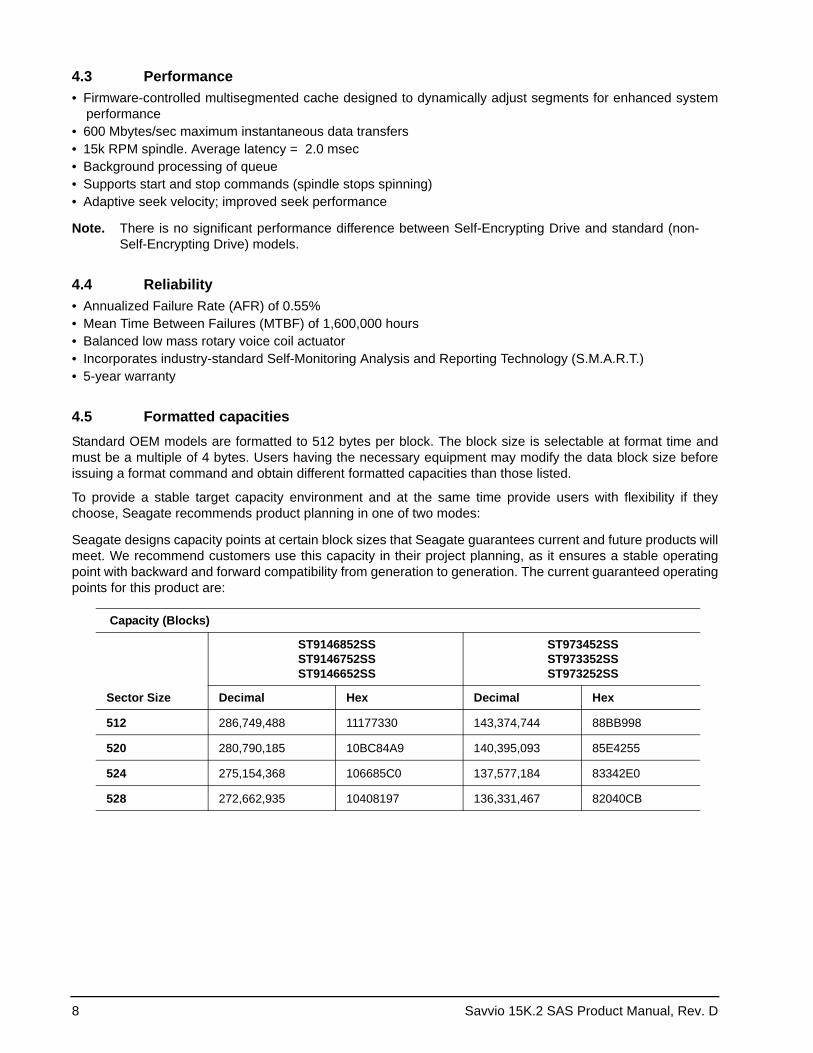
4.5 Formatted capacitiesStandard OEM models are formatted to 512 bytes per block. The block size is selectable at format time and must be a multiple of 4 bytes. Users having the necessary equipment may modify the data block size before issuing a format command and obtain different formatted capacities than those listed.
To provide a stable target capacity environment and at the same time provide users with flexibility if they choose, Seagate recommends product planning in one of two modes:
Seagate designs capacity points at certain block sizes that Seagate guarantees current and future products will meet. We recommend customers use this capacity in their project planning, as it ensures a stable operating point with backward and forward compatibility from generation to generation. The current guaranteed operating points for this product are:
Capacity (Blocks)
Sector Size
ST9146852SSST9146752SSST9146652SS
ST973452SSST973352SSST973252SS
Decimal Hex Decimal Hex
512 286,749,488 11177330 143,374,744 88BB998
520 280,790,185 10BC84A9 140,395,093 85E4255
524 275,154,368 106685C0 137,577,184 83342E0
528 272,662,935 10408197 136,331,467 82040CB
Savvio 15K.2 SAS Product Manual, Rev. D 9
4.6 Programmable drive capacity
Using the Mode Select command, the drive can change its capacity to something less than maximum. See the Mode Select (6) parameter list table in the SAS Interface Manual, part number 100293071. A value of zero in the Number of Blocks field indicates that the drive will not change the capacity it is currently formatted to have. A number other than zero and less than the maximum number of LBAs in the Number of Blocks field changes the total drive capacity to the value in the Number of Blocks field. A value greater than the maximum number of LBAs is rounded down to the maximum capacity.
4.7 Options
You may order the following items which are incorporated at the manufacturing facility during production or packaged before shipping. Some of the options available are (not an exhaustive list of possible options):• Other capacities can be ordered depending on sparing scheme and sector size requested.• Single-unit shipping pack. The drive is normally shipped in bulk packaging to provide maximum protection
against transit damage. Units shipped individually require additional protection as provided by the single unit shipping pack. Users planning single unit distribution should specify this option.
• The Safety and Regulatory Agency Specifications, part number 75789512, is usually included with each standard OEM drive shipped, but extra copies may be ordered.
10 Savvio 15K.2 SAS Product Manual, Rev. D
5.0 Performance characteristics
This section provides detailed information concerning performance-related characteristics and features of Sav-vio drives.
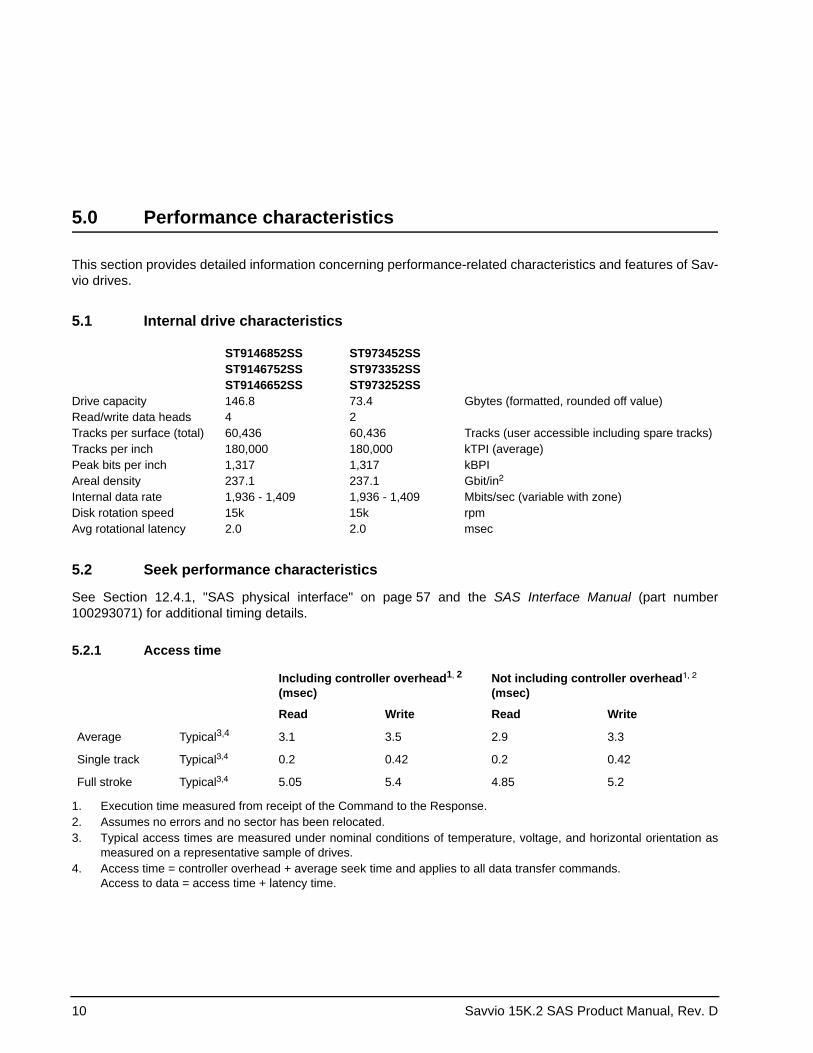
5.1 Internal drive characteristics
ST9146852SS ST973452SS ST9146752SS ST973352SS ST9146652SS ST973252SS
Drive capacity 146.8 73.4 Gbytes (formatted, rounded off value)Read/write data heads 4 2Tracks per surface (total) 60,436 60,436 Tracks (user accessible including spare tracks)Tracks per inch 180,000 180,000 kTPI (average)Peak bits per inch 1,317 1,317 kBPI Areal density 237.1 237.1 Gbit/in2
Internal data rate 1,936 - 1,409 1,936 - 1,409 Mbits/sec (variable with zone)Disk rotation speed 15k 15k rpmAvg rotational latency 2.0 2.0 msec
5.2 Seek performance characteristics
See Section 12.4.1, "SAS physical interface" on page 57 and the SAS Interface Manual (part number 100293071) for additional timing details.
5.2.1 Access time
Including controller overhead 2 1
1. Execution time measured from receipt of the Command to the Response.
,
(msec)
Average Typical 43
3. Typical access times are measured under nominal conditions of temperature, voltage, and horizontal orientation as measured on a representative sample of drives.
,
4. Access time = controller overhead + average seek time and applies to all data transfer commands. Access to data = access time + latency time.
3.1 3.5 2.9 3.3
Single track Typical3,4 0.2 0.42 0.2 0.42
Full stroke Typical3,4 5.05 5.4 4.85 5.2
2. Assumes no errors and no sector has been relocated.
Not including controller overhead1, 2 (msec)
Read Write Read Write
Savvio 15K.2 SAS Product Manual, Rev. D 11
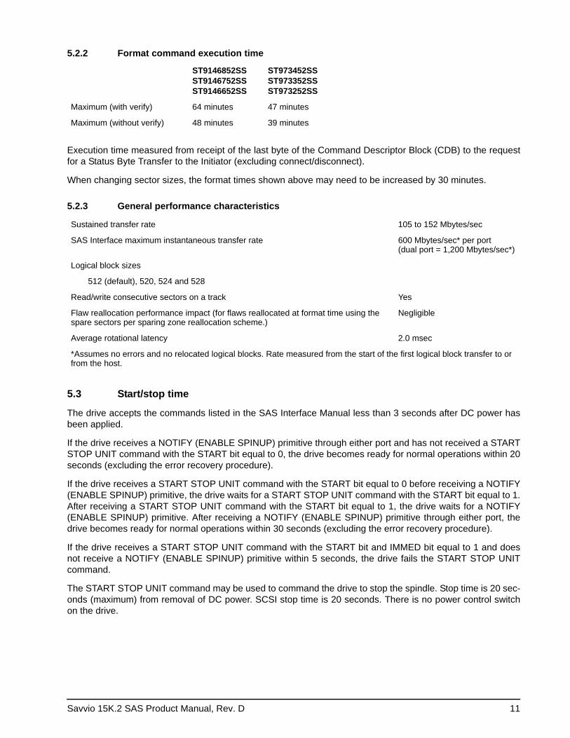
5.2.2 Format command execution time
ST9146852SS ST9146752SS ST9146652SS
ST973452SSST973352SS ST973252SS
Maximum (with verify) 64 minutes 47 minutes
Maximum (without verify) 48 minutes 39 minutes
Execution time measured from receipt of the last byte of the Command Descriptor Block (CDB) to the request for a Status Byte Transfer to the Initiator (excluding connect/disconnect).
When changing sector sizes, the format times shown above may need to be increased by 30 minutes.
5.2.3 General performance characteristics
Sustained transfer rate 105 to 152 Mbytes/sec
SAS Interface maximum instantaneous transfer rate 600 Mbytes/sec* per port (dual port = 1,200 Mbytes/sec*)
Logical block sizes
512 (default), 520, 524 and 528
Read/write consecutive sectors on a track Yes
Flaw reallocation performance impact (for flaws reallocated at format time using the spare sectors per sparing zone reallocation scheme.)
Negligible
Average rotational latency 2.0 msec
*Assumes no errors and no relocated logical blocks. Rate measured from the start of the first logical block transfer to or from the host.
5.3 Start/stop time
The drive accepts the commands listed in the SAS Interface Manual less than 3 seconds after DC power has been applied.
If the drive receives a NOTIFY (ENABLE SPINUP) primitive through either port and has not received a START STOP UNIT command with the START bit equal to 0, the drive becomes ready for normal operations within 20 seconds (excluding the error recovery procedure).
If the drive receives a START STOP UNIT command with the START bit equal to 0 before receiving a NOTIFY (ENABLE SPINUP) primitive, the drive waits for a START STOP UNIT command with the START bit equal to 1. After receiving a START STOP UNIT command with the START bit equal to 1, the drive waits for a NOTIFY (ENABLE SPINUP) primitive. After receiving a NOTIFY (ENABLE SPINUP) primitive through either port, the drive becomes ready for normal operations within 30 seconds (excluding the error recovery procedure).
If the drive receives a START STOP UNIT command with the START bit and IMMED bit equal to 1 and does not receive a NOTIFY (ENABLE SPINUP) primitive within 5 seconds, the drive fails the START STOP UNIT command.
The START STOP UNIT command may be used to command the drive to stop the spindle. Stop time is 20 sec-onds (maximum) from removal of DC power. SCSI stop time is 20 seconds. There is no power control switch on the drive.
12 Savvio 15K.2 SAS Product Manual, Rev. D
5.4 Prefetch/multi-segmented cache control
The drive provides a prefetch (read look-ahead) and multi-segmented cache control algorithms that in many cases can enhance system performance. Cache refers to the drive buffer storage space when it is used in cache operations. To select this feature, the host sends the Mode Select command with the proper values in the applicable bytes in page 08h. Prefetch and cache operations are independent features from the standpoint that each is enabled and disabled independently using the Mode Select command; however, in actual opera-tion, the prefetch feature overlaps cache operation somewhat as described in sections 5.5.1 and 5.5.2.
All default cache and prefetch mode parameter values (Mode Page 08h) for standard OEM versions of this drive family are given in Table 9.
5.5 Cache operation
Note. Refer to the SAS Interface Manual for more detail concerning the cache bits.
Of the 16 Mbytes physical buffer space in the drive, approximately 13,000 kbytes can be used as a cache. The buffer is divided into logical segments from which data is read and to which data is written.
The drive keeps track of the logical block addresses of the data stored in each segment of the buffer. If the cache is enabled (see RCD bit in the SAS Interface Manual ), data requested by the host with a read command is retrieved from the buffer, if possible, before any disk access is initiated. If cache operation is not enabled, the buffer is still used, but only as circular buffer segments during disk medium read operations (disregarding Prefetch operation for the moment). That is, the drive does not check in the buffer segments for the requested read data, but goes directly to the medium to retrieve it. The retrieved data merely passes through some buffer segment on the way to the host. All data transfers to the host are in accordance with buffer-full ratio rules. See the explanation provided with the information about Mode Page 02h (disconnect/reconnect control) in the SAS Interface Manual.
The following is a simplified description of the prefetch/cache operation:
Case A—read command is received and all of the requested logical blocks are already in the cache: 1. Drive transfers the requested logical blocks to the initiator.
Case B—A Read command requests data, and at least one requested logical block is not in any segment of the cache:1. The drive fetches the requested logical blocks from the disk and transfers them into a segment, and then
from there to the host in accordance with the Mode Select Disconnect/Reconnect parameters, page 02h.
2. If the prefetch feature is enabled, refer to section 5.5.2 for operation from this point.
Each cache segment is actually a self-contained circular buffer whose length is an integer number of logical blocks. The drive dynamically creates and removes segments based on the workload. The wrap-around capa-bility of the individual segments greatly enhances the cache’s overall performance.
Note. The size of each segment is not reported by Mode Sense command page 08h, bytes 14 and 15. The value 0XFFFF is always reported regardless of the actual size of the segment. Sending a size specification using the Mode Select command (bytes 14 and 15) does not set up a new segment size. If the STRICT bit in Mode page 00h (byte 2, bit 1) is set to one, the drive responds as it does for any attempt to change an unchangeable parameter.
Savvio 15K.2 SAS Product Manual, Rev. D 13
5.5.1 Caching write data
Write caching is a write operation by the drive that makes use of a drive buffer storage area where the data to be written to the medium is stored while the drive performs the Write command.
If read caching is enabled (RCD=0), then data written to the medium is retained in the cache to be made avail-able for future read cache hits. The same buffer space and segmentation is used as set up for read functions. The buffer segmentation scheme is set up or changed independently, having nothing to do with the state of RCD. When a write command is issued, if RCD=0, the cache is first checked to see if any logical blocks that are to be written are already stored in the cache from a previous read or write command. If there are, the respective cache segments are cleared. The new data is cached for subsequent Read commands.
If the number of write data logical blocks exceed the size of the segment being written into, when the end of the segment is reached, the data is written into the beginning of the same cache segment, overwriting the data that was written there at the beginning of the operation; however, the drive does not overwrite data that has not yet been written to the medium.
If write caching is enabled (WCE=1), then the drive may return Good status on a write command after the data has been transferred into the cache, but before the data has been written to the medium. If an error occurs while writing the data to the medium, and Good status has already been returned, a deferred error will be gen-erated.
The Synchronize Cache command may be used to force the drive to write all cached write data to the medium. Upon completion of a Synchronize Cache command, all data received from previous write commands will have been written to the medium.
Table 9 shows the mode default settings for the drive.
5.5.2 Prefetch operation
If the Prefetch feature is enabled, data in contiguous logical blocks on the disk immediately beyond that which was requested by a Read command are retrieved and stored in the buffer for immediate transfer from the buf-fer to the host on subsequent Read commands that request those logical blocks (this is true even if cache operation is disabled). Though the prefetch operation uses the buffer as a cache, finding the requested data in the buffer is a prefetch hit, not a cache operation hit.
To enable prefetch, use Mode Select page 08h, byte 12, bit 5 (Disable Read Ahead - DRA bit). DRA bit = 0 enables prefetch.
The drive does not use the Max Prefetch field (bytes 8 and 9) or the Prefetch Ceiling field (bytes 10 and 11).
When prefetch (read look-ahead) is enabled (enabled by DRA = 0), the drive enables prefetch of contiguous blocks from the disk when it senses that a prefetch hit will likely occur. The drive disables prefetch when it decides that a prefetch hit is not likely to occur.
14 Savvio 15K.2 SAS Product Manual, Rev. D
6.0 Reliability specifications
The following reliability specifications assume correct host and drive operational interface, including all inter-face timings, power supply voltages, environmental requirements and drive mounting constraints.
6.1 Error rates
The error rates stated in this manual assume the following: • The drive is operated in accordance with this manual using DC power as defined in paragraph 7.2, "DC
power requirements."• Errors caused by host system failures are excluded from error rate computations.• Assume random data.• Default OEM error recovery settings are applied. This includes AWRE, ARRE, full read retries, full write
retries and full retry time.
6.1.1 Recoverable Errors
Recoverable errors are those detected and corrected by the drive, and do not require user intervention.
Recoverable Data errors will use correction, although ECC on-the-fly is not considered for purposes of recov-ered error specifications.
Recovered Data error rate is determined using read bits transferred for recoverable errors occurring during a read, and using write bits transferred for recoverable errors occurring during a write.
6.1.2 Unrecoverable Errors
An unrecoverable data error is defined as a failure of the drive to recover data from the media. These errors occur due to head/media or write problems. Unrecoverable data errors are only detected during read opera-tions, but not caused by the read. If an unrecoverable data error is detected, a MEDIUM ERROR (03h) in the Sense Key will be reported. Multiple unrecoverable data errors resulting from the same cause are treated as 1 error.
Seek error rate: Less than 10 errors in 108 seeksRead Error Rates1
1. Error rate specified with automatic retries and data correction with ECC enabled and all flaws reallocated.
Recovered Data Less than 1 error in 1012 bits transferred (OEM default settings)Unrecovered Data Less than 1 sector in 1016 bits transferredMiscorrected Data Less than 1 sector in 1021 bits transferred
Interface error rate: Less than 1 error in 1012 bits transferred Mean Time Between Failure (MTBF): 1,600,000 hoursAnnualized Failure Rate (AFR) 0.55%Preventive maintenance: None required
Savvio 15K.2 SAS Product Manual, Rev. D 15
6.1.3 Seek errors
A seek error is defined as a failure of the drive to position the heads to the addressed track. After detecting an initial seek error, the drive automatically performs an error recovery process. If the error recovery process fails, a seek positioning error (Error code = 15h or 02h) will be reported with a Hardware error (04h) in the Sense Key. Recoverable seek errors are specified at Less than 10 errors in 108 seeks. Unrecoverable seek errors (Sense Key = 04h) are classified as drive failures.
6.1.4 Interface errors
An interface error is defined as a failure of the receiver on a port to recover the data as transmitted by the device port connected to the receiver. The error may be detected as a running disparity error, illegal code, loss of word sync, or CRC error.
6.2 Reliability and service
You can enhance the reliability of Savvio disk drives by ensuring that the drive receives adequate cooling. Sec-tion 7.0 provides temperature measurements and other information that may be used to enhance the service life of the drive. Section 11.2 provides recommended air-flow information.
6.2.1 Annualized Failure Rate (AFR) and Mean Time Between Failure (MTBF)
The production disk drive shall achieve an AFR of 0.55% (MTBF of 1,600,000 hours) when operated in an environment that ensures the HDA case temperatures do not exceed the values specified in Section 7.4. Oper-ation at case temperatures outside the specifications in Section 7.4 may increase the product AFR (decrease the MTBF). The AFR (MTBF) is a population statistic not relevant to individual units.
The AFR (MTBF) specification is based on the following assumptions for Business Critical Storage System environments:
• 8,760 power-on hours per year.• 250 average on/off cycles per year.• Operations at nominal voltages.• Systems will provide adequate cooling to ensure the case temperatures specified in Section 7.4 are not
exceeded. Temperatures outside the specifications in Section 7.4 will increase the product AFR and decrease the MTBF.
6.2.2 Preventive maintenance
No routine scheduled preventive maintenance is required.
6.2.3 Hot plugging the drive
When a disk is powered on by switching the power or hot plugged, the drive runs a self test before attempting to communicate on its’ interfaces. When the self test completes successfully, the drive initiates a Link Reset starting with OOB. An attached device should respond to the link reset. If the link reset attempt fails, or any time the drive looses sync, the drive initiated link reset. The drive will initiate link reset once per second but alternates between port A and B. Therefore each port will attempt a link reset once per 2 seconds assuming both ports are out of sync.
If the self-test fails, the drive does not respond to link reset on the failing port.
Note. It is the responsibility of the systems integrator to assure that no temperature, energy, voltage haz-ard, or ESD potential hazard is presented during the hot connect/disconnect operation. Discharge the static electricity from the drive carrier prior to inserting it into the system.
16 Savvio 15K.2 SAS Product Manual, Rev. D
Caution. The drive motor must come to a complete stop prior to changing the plane of operation. This time is required to insure data integrity.
6.2.4 S.M.A.R.T.
S.M.A.R.T. is an acronym for Self-Monitoring Analysis and Reporting Technology. This technology is intended to recognize conditions that indicate imminent drive failure and is designed to provide sufficient warning of a failure to allow you to back up the data before an actual failure occurs.
Note. The drive’s firmware monitors specific attributes for degradation over time but can’t predict instanta-neous drive failures.
Each monitored attribute has been selected to monitor a specific set of failure conditions in the operating per-formance of the drive and the thresholds are optimized to minimize “false” and “failed” predictions.
Controlling S.M.A.R.T.
The operating mode of S.M.A.R.T. is controlled by the DEXCPT and PERF bits on the Informational Exceptions Control mode page (1Ch). Use the DEXCPT bit to enable or disable the S.M.A.R.T. feature. Setting the DEX-CPT bit disables all S.M.A.R.T. functions. When enabled, S.M.A.R.T. collects on-line data as the drive performs normal read and write operations. When the PERF bit is set, the drive is considered to be in “On-line Mode Only” and will not perform off-line functions.
You can measure off-line attributes and force the drive to save the data by using the Rezero Unit command. Forcing S.M.A.R.T. resets the timer so that the next scheduled interrupt is in two hours.
You can interrogate the drive through the host to determine the time remaining before the next scheduled mea-surement and data logging process occurs. To accomplish this, issue a Log Sense command to log page 0x3E. This allows you to control when S.M.A.R.T. interruptions occur. Forcing S.M.A.R.T. with the RTZ command resets the timer.
Performance impact
S.M.A.R.T. attribute data is saved to the disk so that the events that caused a predictive failure can be recre-ated. The drive measures and saves parameters once every two hours subject to an idle period on the drive interfaces. The process of measuring off-line attribute data and saving data to the disk is uninterruptable. The maximum on-line only processing delay is summarized below:
Reporting control
Reporting is controlled by the MRIE bits in the Informational Exceptions Control mode page (1Ch). Subject to the reporting method, the firmware will issue to the host an 01-5Dxx sense code. The error code is preserved through bus resets and power cycles.
Determining rate
S.M.A.R.T. monitors the rate at which errors occur and signals a predictive failure if the rate of degraded errors increases to an unacceptable level. To determine rate, error events are logged and compared to the number of total operations for a given attribute. The interval defines the number of operations over which to measure the rate. The counter that keeps track of the current number of operations is referred to as the Interval Counter.
Maximum processing delay
On-line only delay DEXCPT = 0, PERF = 1
Fully-enabled delay DEXCPT = 0, PERF = 0
S.M.A.R.T. delay times 118 milliseconds 146 milliseconds
Savvio 15K.2 SAS Product Manual, Rev. D 17
S.M.A.R.T. measures error rates. All errors for each monitored attribute are recorded. A counter keeps track of the number of errors for the current interval. This counter is referred to as the Failure Counter.
Error rate is the number of errors per operation. The algorithm that S.M.A.R.T. uses to record rates of error is to set thresholds for the number of errors and their interval. If the number of errors exceeds the threshold before the interval expires, the error rate is considered to be unacceptable. If the number of errors does not exceed the threshold before the interval expires, the error rate is considered to be acceptable. In either case, the inter-val and failure counters are reset and the process starts over.
Predictive failures
S.M.A.R.T. signals predictive failures when the drive is performing unacceptably for a period of time. The firm-ware keeps a running count of the number of times the error rate for each attribute is unacceptable. To accom-plish this, a counter is incremented each time the error rate is unacceptable and decremented (not to exceed zero) whenever the error rate is acceptable. If the counter continually increments such that it reaches the pre-dictive threshold, a predictive failure is signaled. This counter is referred to as the Failure History Counter. There is a separate Failure History Counter for each attribute.
6.2.5 Thermal monitor
Savvio drives implement a temperature warning system which:1. Signals the host if the temperature exceeds a value which would threaten the drive.
2. Signals the host if the temperature exceeds a user-specified value.
3. Saves a S.M.A.R.T. data frame on the drive which exceeds the threatening temperature value.
A temperature sensor monitors the drive temperature and issues a warning over the interface when the tem-perature exceeds a set threshold. The temperature is measured at power-up and then at ten-minute intervals after power-up.
The thermal monitor system generates a warning code of 01-0B01 when the temperature exceeds the speci-fied limit in compliance with the SCSI standard. The drive temperature is reported in the FRU code field of mode sense data. You can use this information to determine if the warning is due to the temperature exceeding the drive threatening temperature or the user-specified temperature.
This feature is controlled by the Enable Warning (EWasc) bit, and the reporting mechanism is controlled by the Method of Reporting Informational Exceptions field (MRIE) on the Informational Exceptions Control (IEC) mode page (1Ch).
The current algorithm implements two temperature trip points. The first trip point is set at 65°C which is the maximum temperature limit according to the drive specification. The second trip point is user-selectable using the Log Select command. The reference temperature parameter in the temperature log page (see Table 1) can be used to set this trip point. The default value for this drive is 65°C, however, you can set it to any value in the range of 0 to 65°C. If you specify a temperature greater than 65°C in this field, the temperature is rounded down to 65°C. A sense code is sent to the host to indicate the rounding of the parameter field.
Table 1: Temperature Log Page (0Dh)
Parameter Code Description
0000h Primary Temperature
0001h Reference Temperature
18 Savvio 15K.2 SAS Product Manual, Rev. D
6.2.6 Drive Self Test (DST)
Drive Self Test (DST) is a technology designed to recognize drive fault conditions that qualify the drive as a failed unit. DST validates the functionality of the drive at a system level. There are two test coverage options implemented in DST:1. Extended test2. Short test
The most thorough option is the extended test that performs various tests on the drive and scans every logical block address (LBA) of the drive. The short test is time-restricted and limited in length—it does not scan the entire media surface, but does some fundamental tests and scans portions of the media.
If DST encounters an error during either of these tests, it reports a fault condition. If the drive fails the test, remove it from service and return it to Seagate for service.
6.2.6.1 DST failure definition
The drive will present a “diagnostic failed” condition through the self-tests results value of the diagnostic log page if a functional failure is encountered during DST. The channel and servo parameters are not modified to test the drive more stringently, and the number of retries are not reduced. All retries and recovery processes are enabled during the test. If data is recoverable, no failure condition will be reported regardless of the number of retries required to recover the data.
The following conditions are considered DST failure conditions:• Seek error after retries are exhausted• Track-follow error after retries are exhausted• Read error after retries are exhausted• Write error after retries are exhausted
Recovered errors will not be reported as diagnostic failures.
6.2.6.2 Implementation
This section provides all of the information necessary to implement the DST function on this drive.
6.2.6.2.1 State of the drive prior to testing
The drive must be in a ready state before issuing the Send Diagnostic command. There are multiple reasons why a drive may not be ready, some of which are valid conditions, and not errors. For example, a drive may be in process of doing a format, or another DST. It is the responsibility of the host application to determine the “not ready” cause.
While not technically part of DST, a Not Ready condition also qualifies the drive to be returned to Seagate as a failed drive.
A Drive Not Ready condition is reported by the drive under the following conditions:• Motor will not spin• Motor will not lock to speed• Servo will not lock on track• Drive cannot read configuration tables from the disk
In these conditions, the drive responds to a Test Unit Ready command with an 02/04/00 or 02/04/03 code.
6.2.6.2.2 Invoking DST
To invoke DST, submit the Send Diagnostic command with the appropriate Function Code (001b for the short test or 010b for the extended test) in bytes 1, bits 5, 6, and 7.
Savvio 15K.2 SAS Product Manual, Rev. D 19
6.2.6.2.3 Short and extended tests
DST has two testing options:1. short2. extended
These testing options are described in the following two subsections.
Each test consists of three segments: an electrical test segment, a servo test segment, and a read/verify scan segment.
Short test (Function Code: 001b)
The purpose of the short test is to provide a time-limited test that tests as much of the drive as possible within 120 seconds. The short test does not scan the entire media surface, but does some fundamental tests and scans portions of the media. A complete read/verify scan is not performed and only factual failures will report a fault condition. This option provides a quick confidence test of the drive.
Extended test (Function Code: 010b)
The objective of the extended test option is to empirically test critical drive components. For example, the seek tests and on-track operations test the positioning mechanism. The read operation tests the read head element and the media surface. The write element is tested through read/write/read operations. The integrity of the media is checked through a read/verify scan of the media. Motor functionality is tested by default as a part of these tests.
The anticipated length of the Extended test is reported through the Control Mode page.
6.2.6.2.4 Log page entries
When the drive begins DST, it creates a new entry in the Self-test Results Log page. The new entry is created by inserting a new self-test parameter block at the beginning of the self-test results log parameter section of the log page. Existing data will be moved to make room for the new parameter block. The drive reports 20 param-eter blocks in the log page. If there are more than 20 parameter blocks, the least recent parameter block will be deleted. The new parameter block will be initialized as follows:1. The Function Code field is set to the same value as sent in the DST command
2. The Self-Test Results Value field is set to Fh
3. The drive will store the log page to non-volatile memory
After a self-test is complete or has been aborted, the drive updates the Self-Test Results Value field in its Self-Test Results Log page in non-volatile memory. The host may use Log Sense to read the results from up to the last 20 self-tests performed by the drive. The self-test results value is a 4-bit field that reports the results of the test. If the field is set to zero, the drive passed with no errors detected by the DST. If the field is not set to zero, the test failed for the reason reported in the field.
The drive will report the failure condition and LBA (if applicable) in the Self-test Results Log parameter. The Sense key, ASC, ASCQ, and FRU are used to report the failure condition.
6.2.6.2.5 Abort
There are several ways to abort a diagnostic. You can use a SCSI Bus Reset or a Bus Device Reset message to abort the diagnostic.
You can abort a DST executing in background mode by using the abort code in the DST Function Code field. This will cause a 01 (self-test aborted by the application client) code to appear in the self-test results values log. All other abort mechanisms will be reported as a 02 (self-test routine was interrupted by a reset condition).
20 Savvio 15K.2 SAS Product Manual, Rev. D
6.2.7 Product warranty
Beginning on the date of shipment to the customer and continuing for the period specified in your purchase contract, Seagate warrants that each product (including components and subassemblies) that fails to function properly under normal use due to defect in materials or workmanship or due to nonconformance to the applica-ble specifications will be repaired or replaced, at Seagate’s option and at no charge to the customer, if returned by customer at customer’s expense to Seagate’s designated facility in accordance with Seagate’s warranty procedure. Seagate will pay for transporting the repair or replacement item to the customer. For more detailed warranty information, refer to the standard terms and conditions of purchase for Seagate products on your pur-chase documentation.
The remaining warranty for a particular drive can be determined by calling Seagate Customer Service at 1-800-468-3472. You can also determine remaining warranty using the Seagate web site (www.seagate.com). The drive serial number is required to determine remaining warranty information.
ShippingWhen transporting or shipping a drive, use only a Seagate-approved container. Keep your original box. Sea-gate approved containers are easily identified by the Seagate Approved Package label. Shipping a drive in a non-approved container voids the drive warranty.
Seagate repair centers may refuse receipt of components improperly packaged or obviously damaged in tran-sit. Contact your authorized Seagate distributor to purchase additional boxes. Seagate recommends shipping by an air-ride carrier experienced in handling computer equipment.
Product repair and return information
Seagate customer service centers are the only facilities authorized to service Seagate drives. Seagate does not sanction any third-party repair facilities. Any unauthorized repair or tampering with the factory seal voids the warranty.
Savvio 15K.2 SAS Product Manual, Rev. D 21
7.0 Physical/electrical specifications
This section provides information relating to the physical and electrical characteristics of the drive.
7.1 AC power requirements
None.
7.2 DC power requirements
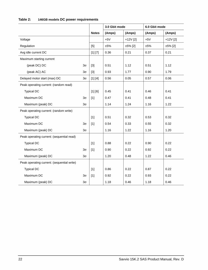
The voltage and current requirements for a single drive are shown below. Values indicated apply at the drive connector.
The standard drive models and the SED drive models have identical hardware, however the security and encryption portion of the drive controller ASIC is enabled and functional in the SED models. This represents a small additional drain on the 5V supply of about 30mA and a commensurate increase of about 150mW in power consumption. There is no additional drain on the 12V supply.
22 Savvio 15K.2 SAS Product Manual, Rev. D
Table 2: 146GB models DC power requirements
Notes
3.0 Gbit mode 6.0 Gbit mode
(Amps) (Amps) (Amps) (Amps)
Voltage +5V +12V [2] +5V +12V [2]
Regulation [5] ±5% ±5% [2] ±5% ±5% [2]
Avg idle current DC [1] [7] 0.36 0.21 0.37 0.21
Maximum starting current
(peak DC) DC 3σ [3] 0.51 1.12 0.51 1.12
(peak AC) AC 3σ [3] 0.93 1.77 0.90 1.79
Delayed motor start (max) DC 3σ [1] [4] 0.56 0.05 0.57 0.06
Peak operating current: (random read)
Typical DC [1] [6] 0.45 0.41 0.46 0.41
Maximum DC 3σ [1] 0.47 0.41 0.48 0.41
Maximum (peak) DC 3σ 1.14 1.24 1.16 1.22
Peak operating current: (random write)
Typical DC [1] 0.51 0.32 0.53 0.32
Maximum DC 3σ [1] 0.54 0.33 0.55 0.32
Maximum (peak) DC 3σ 1.16 1.22 1.16 1.20
Peak operating current: (sequential read)
Typical DC [1] 0.88 0.22 0.90 0.22
Maximum DC 3σ [1] 0.90 0.22 0.92 0.22
Maximum (peak) DC 3σ 1.20 0.48 1.22 0.46
Peak operating current: (sequential write)
Typical DC [1] 0.86 0.22 0.87 0.22
Maximum DC 3σ [1] 0.92 0.22 0.93 0.22
Maximum (peak) DC 3σ 1.18 0.46 1.18 0.46
Savvio 15K.2 SAS Product Manual, Rev. D 23
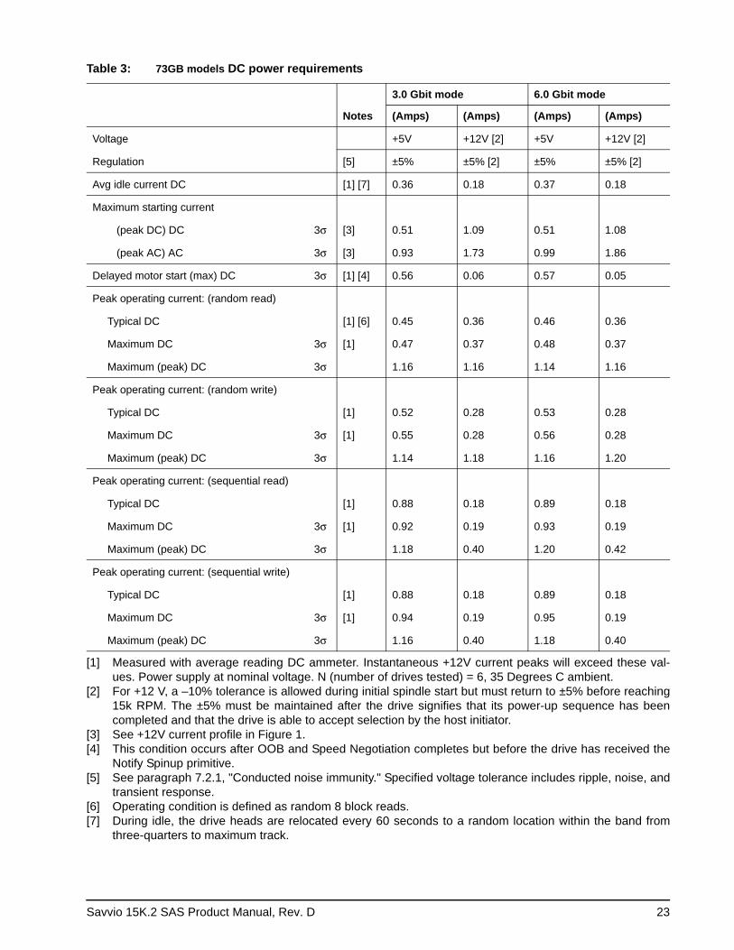
[1] Measured with average reading DC ammeter. Instantaneous +12V current peaks will exceed these val-ues. Power supply at nominal voltage. N (number of drives tested) = 6, 35 Degrees C ambient.
[2] For +12 V, a –10% tolerance is allowed during initial spindle start but must return to ±5% before reaching 15k RPM. The ±5% must be maintained after the drive signifies that its power-up sequence has been completed and that the drive is able to accept selection by the host initiator.
[3] See +12V current profile in Figure 1.[4] This condition occurs after OOB and Speed Negotiation completes but before the drive has received the
Notify Spinup primitive.[5] See paragraph 7.2.1, "Conducted noise immunity." Specified voltage tolerance includes ripple, noise, and
transient response.[6] Operating condition is defined as random 8 block reads.[7] During idle, the drive heads are relocated every 60 seconds to a random location within the band from
three-quarters to maximum track.
Table 3: 73GB models DC power requirements
Notes
3.0 Gbit mode 6.0 Gbit mode
(Amps) (Amps) (Amps) (Amps)
Voltage +5V +12V [2] +5V +12V [2]
Regulation [5] ±5% ±5% [2] ±5% ±5% [2]
Avg idle current DC [1] [7] 0.36 0.18 0.37 0.18
Maximum starting current
(peak DC) DC 3σ [3] 0.51 1.09 0.51 1.08
(peak AC) AC 3σ [3] 0.93 1.73 0.99 1.86
Delayed motor start (max) DC 3σ [1] [4] 0.56 0.06 0.57 0.05
Peak operating current: (random read)
Typical DC [1] [6] 0.45 0.36 0.46 0.36
Maximum DC 3σ [1] 0.47 0.37 0.48 0.37
Maximum (peak) DC 3σ 1.16 1.16 1.14 1.16
Peak operating current: (random write)
Typical DC [1] 0.52 0.28 0.53 0.28
Maximum DC 3σ [1] 0.55 0.28 0.56 0.28
Maximum (peak) DC 3σ 1.14 1.18 1.16 1.20
Peak operating current: (sequential read)
Typical DC [1] 0.88 0.18 0.89 0.18
Maximum DC 3σ [1] 0.92 0.19 0.93 0.19
Maximum (peak) DC 3σ 1.18 0.40 1.20 0.42
Peak operating current: (sequential write)
Typical DC [1] 0.88 0.18 0.89 0.18
Maximum DC 3σ [1] 0.94 0.19 0.95 0.19
Maximum (peak) DC 3σ 1.16 0.40 1.18 0.40
24 Savvio 15K.2 SAS Product Manual, Rev. D
General DC power requirement notes.1. Minimum current loading for each supply voltage is not less than 1.7% of the maximum operating current
shown. 2. The +5V and +12V supplies should employ separate ground returns. 3. Where power is provided to multiple drives from a common supply, careful consideration for individual
drive power requirements should be noted. Where multiple units are powered on simultaneously, the peak starting current must be available to each device.
4. Parameters, other than spindle start, are measured after a 10-minute warm up.5. No terminator power.
7.2.1 Conducted noise immunity
Noise is specified as a periodic and random distribution of frequencies covering a band from DC to 10 MHz. Maximum allowed noise values given below are peak-to-peak measurements and apply at the drive power connector.
7.2.2 Power sequencing
The drive does not require power sequencing. The drive protects against inadvertent writing during power-up and down.
+5V = 250 mV pp from 100 Hz to 20 MHz.
+12V = 800 mV pp from 100 0Hz to 8 KHz. 450 mV pp from 8 KHz to 20 KHz. 250 mV pp from 20 KHz to 5 MHz.
Savvio 15K.2 SAS Product Manual, Rev. D 25
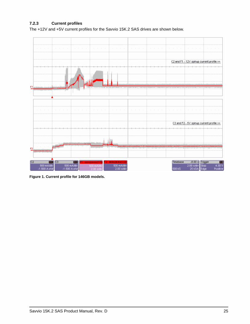
7.2.3 Current profiles The +12V and +5V current profiles for the Savvio 15K.2 SAS drives are shown below.
Figure 1. Current profile for 146GB models.
26 Savvio 15K.2 SAS Product Manual, Rev. D
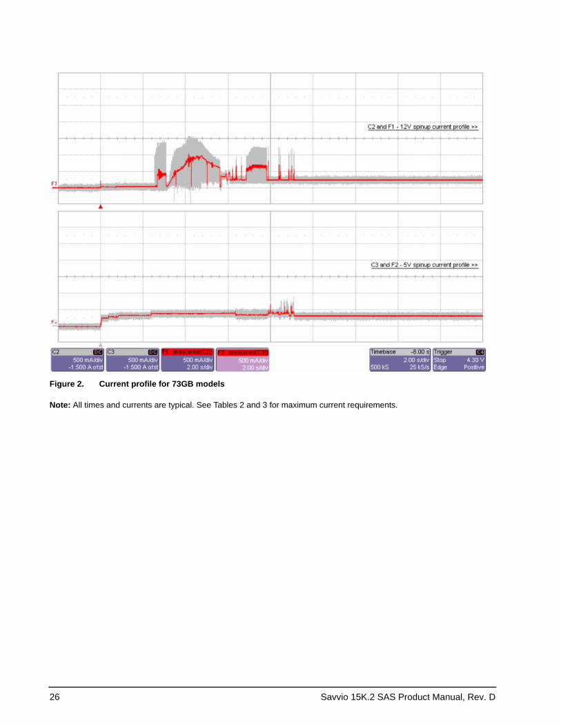
Figure 2. Current profile for 73GB models
Note: All times and currents are typical. See Tables 2 and 3 for maximum current requirements.
Savvio 15K.2 SAS Product Manual, Rev. D 27
7.3 Power dissipation
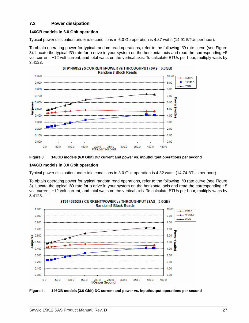
146GB models in 6.0 Gbit operation
Typical power dissipation under idle conditions in 6.0 Gb operation is 4.37 watts (14.91 BTUs per hour).
To obtain operating power for typical random read operations, refer to the following I/O rate curve (see Figure 3). Locate the typical I/O rate for a drive in your system on the horizontal axis and read the corresponding +5 volt current, +12 volt current, and total watts on the vertical axis. To calculate BTUs per hour, multiply watts by 3.4123.
Figure 3. 146GB models (6.0 Gbit) DC current and power vs. input/output operations per second
146GB models in 3.0 Gbit operation
Typical power dissipation under idle conditions in 3.0 Gbit operation is 4.32 watts (14.74 BTUs per hour).
To obtain operating power for typical random read operations, refer to the following I/O rate curve (see Figure 3). Locate the typical I/O rate for a drive in your system on the horizontal axis and read the corresponding +5 volt current, +12 volt current, and total watts on the vertical axis. To calculate BTUs per hour, multiply watts by 3.4123.
Figure 4. 146GB models (3.0 Gbit) DC current and power vs. input/output operations per second
28 Savvio 15K.2 SAS Product Manual, Rev. D
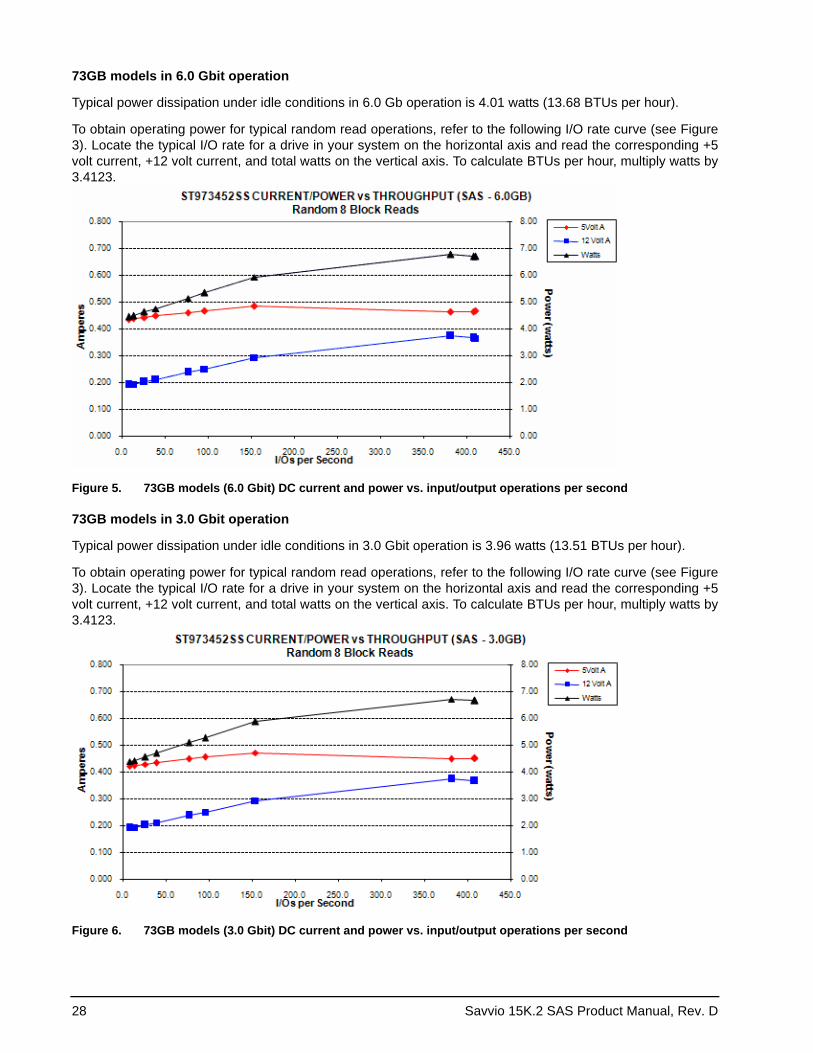
73GB models in 6.0 Gbit operation
Typical power dissipation under idle conditions in 6.0 Gb operation is 4.01 watts (13.68 BTUs per hour).
To obtain operating power for typical random read operations, refer to the following I/O rate curve (see Figure 3). Locate the typical I/O rate for a drive in your system on the horizontal axis and read the corresponding +5 volt current, +12 volt current, and total watts on the vertical axis. To calculate BTUs per hour, multiply watts by 3.4123.
Figure 5. 73GB models (6.0 Gbit) DC current and power vs. input/output operations per second
73GB models in 3.0 Gbit operation
Typical power dissipation under idle conditions in 3.0 Gbit operation is 3.96 watts (13.51 BTUs per hour).
To obtain operating power for typical random read operations, refer to the following I/O rate curve (see Figure 3). Locate the typical I/O rate for a drive in your system on the horizontal axis and read the corresponding +5 volt current, +12 volt current, and total watts on the vertical axis. To calculate BTUs per hour, multiply watts by 3.4123.
Figure 6. 73GB models (3.0 Gbit) DC current and power vs. input/output operations per second
Savvio 15K.2 SAS Product Manual, Rev. D 29
7.4 Environmental limits
Temperature and humidity values experienced by the drive must be such that condensation does not occur on any drive part. Altitude and atmospheric pressure specifications are referenced to a standard day at 58.7°F (14.8°C). Maximum wet bulb temperature is 82°F (28°C).
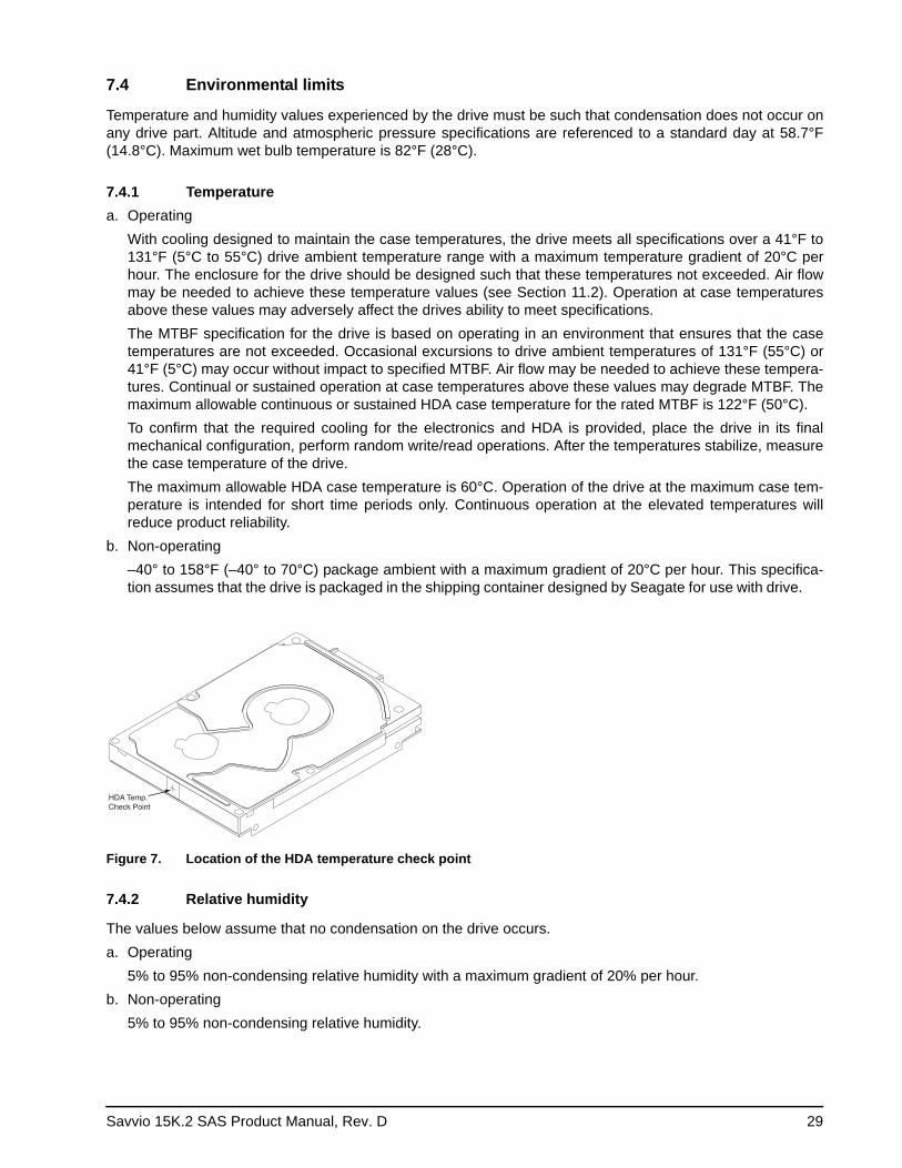
7.4.1 Temperaturea. Operating
With cooling designed to maintain the case temperatures, the drive meets all specifications over a 41°F to 131°F (5°C to 55°C) drive ambient temperature range with a maximum temperature gradient of 20°C per hour. The enclosure for the drive should be designed such that these temperatures not exceeded. Air flow may be needed to achieve these temperature values (see Section 11.2). Operation at case temperatures above these values may adversely affect the drives ability to meet specifications.The MTBF specification for the drive is based on operating in an environment that ensures that the case temperatures are not exceeded. Occasional excursions to drive ambient temperatures of 131°F (55°C) or 41°F (5°C) may occur without impact to specified MTBF. Air flow may be needed to achieve these tempera-tures. Continual or sustained operation at case temperatures above these values may degrade MTBF. The maximum allowable continuous or sustained HDA case temperature for the rated MTBF is 122°F (50°C).To confirm that the required cooling for the electronics and HDA is provided, place the drive in its final mechanical configuration, perform random write/read operations. After the temperatures stabilize, measure the case temperature of the drive.The maximum allowable HDA case temperature is 60°C. Operation of the drive at the maximum case tem-perature is intended for short time periods only. Continuous operation at the elevated temperatures will reduce product reliability.
b. Non-operating–40° to 158°F (–40° to 70°C) package ambient with a maximum gradient of 20°C per hour. This specifica-tion assumes that the drive is packaged in the shipping container designed by Seagate for use with drive.
HDA Temp.Check Point
Figure 7. Location of the HDA temperature check point
7.4.2 Relative humidity
The values below assume that no condensation on the drive occurs.a. Operating
5% to 95% non-condensing relative humidity with a maximum gradient of 20% per hour.b. Non-operating
5% to 95% non-condensing relative humidity.
30 Savvio 15K.2 SAS Product Manual, Rev. D
7.4.3 Effective altitude (sea level)a. Operating
–1,000 to +10,000 feet (–305 to +3,048 meters)b. Non-operating
–1,000 to +40,000 feet (–305 to +12,192 meters)
7.4.4 Shock and vibration
Shock and vibration limits specified in this document are measured directly on the drive chassis. If the drive is installed in an enclosure to which the stated shock and/or vibration criteria is applied, resonances may occur internally to the enclosure resulting in drive movement in excess of the stated limits. If this situation is apparent, it may be necessary to modify the enclosure to minimize drive movement.
The limits of shock and vibration defined within this document are specified with the drive mounted by any of the four methods shown in Figure 8, and in accordance with the restrictions of Section 11.3.
7.4.4.1 Shocka. Operating—normal
The drive, as installed for normal operation, shall operate error free while subjected to intermittent shock not exceeding 15 Gs at a maximum duration of 11 msec (half sinewave). The drive, as installed for normal operation, shall operate error free while subjected to intermittent shock not exceeding 20 Gs at a maximum duration of 2 msec (half sinewave). Shock may be applied in the X, Y, or Z axis.
b. Operating—abnormalEquipment, as installed for normal operation, does not incur physical damage while subjected to intermit-tent shock not exceeding 40 Gs at a maximum duration of 11 msec (half sinewave) and 25 Gs as a maxi-mum duration of 2 msec (half sinewave). Shock occurring at abnormal levels may promote degraded operational performance during the abnormal shock period. Specified operational performance will continue when normal operating shock levels resume. Shock may be applied in the X, Y, or Z axis. Shock is not to be repeated more than two times per second.
c. Non-operatingThe limits of non-operating shock shall apply to all conditions of handling and transportation. This includes both isolated drives and integrated drives.The drive subjected to nonrepetitive shock not exceeding 80 Gs at a maximum duration of 11 msec (half sinewave) shall not exhibit device damage or performance degradation. Shock may be applied in the X, Y, or Z axis.The drive subjected to nonrepetitive shock not exceeding 300 Gs at a maximum duration of 2 msec (half sinewave) does not exhibit device damage or performance degradation. Shock may be applied in the X, Y, or Z axis.The drive subjected to nonrepetitve shock not exceeding 150 Gs at a maximum duration of 0.5 msec (half sinewave) does not exhibit device damage or performance degradation. Shock may be applied in the X, Y, or Z axis.
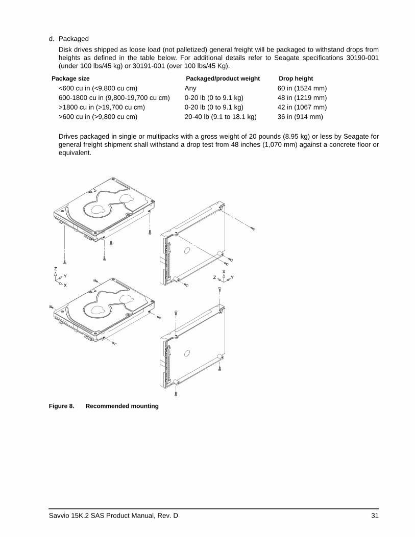
Savvio 15K.2 SAS Product Manual, Rev. D 31
d. PackagedDisk drives shipped as loose load (not palletized) general freight will be packaged to withstand drops from heights as defined in the table below. For additional details refer to Seagate specifications 30190-001 (under 100 lbs/45 kg) or 30191-001 (over 100 lbs/45 Kg).
Package size Packaged/product weight Drop height<600 cu in (<9,800 cu cm) Any 60 in (1524 mm)600-1800 cu in (9,800-19,700 cu cm) 0-20 lb (0 to 9.1 kg) 48 in (1219 mm)>1800 cu in (>19,700 cu cm) 0-20 lb (0 to 9.1 kg) 42 in (1067 mm)>600 cu in (>9,800 cu cm) 20-40 lb (9.1 to 18.1 kg) 36 in (914 mm)
Drives packaged in single or multipacks with a gross weight of 20 pounds (8.95 kg) or less by Seagate for general freight shipment shall withstand a drop test from 48 inches (1,070 mm) against a concrete floor or equivalent.
Z
Y
X
Z YX
Figure 8. Recommended mounting
32 Savvio 15K.2 SAS Product Manual, Rev. D
7.4.4.2 Vibrationa. Operating—normal
The drive as installed for normal operation, shall comply with the complete specified performance while subjected to continuous vibration not exceeding
5 - 500 Hz, swept sine: 0.5 G (zero to peak) 10 - 500 Hz, random: 0.00051 G2/Hz
Vibration may be applied in the X, Y, or Z axis.b. Operating—abnormal
Equipment as installed for normal operation shall not incur physical damage while subjected to periodic vibration not exceeding:
15 minutes of duration at major resonant frequency5 - 500 Hz, swept sine: 0.75 G (zero to peak) 10 - 500 Hz, random: 0.0029 G2/Hz
Vibration occurring at these levels may degrade operational performance during the abnormal vibration period. Specified operational performance will continue when normal operating vibration levels are resumed. This assumes system recovery routines are available.
c. Non-operatingThe limits of non-operating vibration shall apply to all conditions of handling and transportation. This includes both isolated drives and integrated drives.The drive shall not incur physical damage or degraded performance as a result of continuous vibration not exceeding:
5 - 22 Hz, swept sine: 0.25 G, (zero to peak)22 - 350 Hz, swept sine: 5.0 G (zero to peak)350 - 500 Hz, swept sine: 1.0 G (zero to peak)10 - 500 Hz, random: 0.0118 G2/Hz
Vibration may be applied in the X, Y, or Z axis.
7.4.5 Air cleanliness
The drive is designed to operate in a typical office environment with minimal environmental control.
7.4.6 Corrosive environment
Seagate electronic drive components pass accelerated corrosion testing equivalent to 10 years exposure to light industrial environments containing sulfurous gases, chlorine and nitric oxide, classes G and H per ASTM B845. However, this accelerated testing cannot duplicate every potential application environment.
Users should use caution exposing any electronic components to uncontrolled chemical pollutants and corro-sive chemicals as electronic drive component reliability can be affected by the installation environment. The sil-ver, copper, nickel and gold films used in Seagate products are especially sensitive to the presence of sulfide, chloride, and nitrate contaminants. Sulfur is found to be the most damaging. In addition, electronic components should never be exposed to condensing water on the surface of the printed circuit board assembly (PCBA) or exposed to an ambient relative humidity greater than 95%. Materials used in cabinet fabrication, such as vulca-nized rubber, that can outgas corrosive compounds should be minimized or eliminated. The useful life of any electronic equipment may be extended by replacing materials near circuitry with sulfide-free alternatives.
Savvio 15K.2 SAS Product Manual, Rev. D 33
7.4.7 Acoustics
Sound power during idle mode shall be 3.25 bels typical when measured to ISO 7779 specification.
Sound power during operating mode shall be 3.35 bels typical when measured to ISO 7779 specification.
There will not be any discrete tones more than 10 dB above the masking noise on typical drives when mea-sured according to Seagate specification 30553-001. There will not be any tones more than 24 dB above the masking noise on any drive.
7.4.8 Electromagnetic susceptibility
See Section 3.1.1.1.
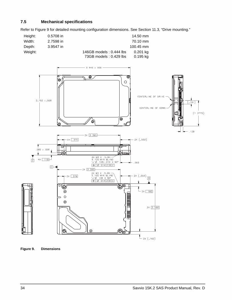
34 Savvio 15K.2 SAS Product Manual, Rev. D
7.5 Mechanical specifications
Refer to Figure 9 for detailed mounting configuration dimensions. See Section 11.3, “Drive mounting.”
Figure 9. Dimensions
Height: 0.5708 in 14.50 mmWidth: 2.7598 in 70.10 mmDepth: 3.9547 in 100.45 mmWeight: 146GB models : 0.444 lbs
73GB models : 0.429 lbs 0.201 kg 0.195 kg
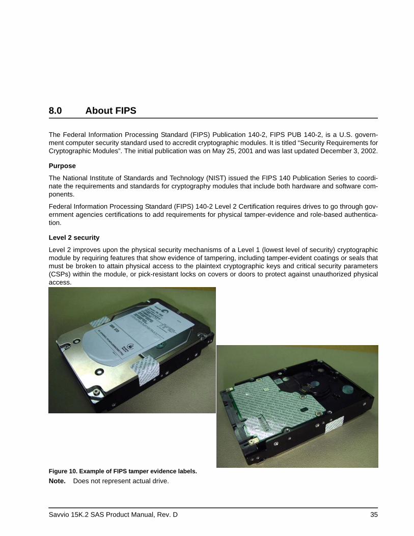
Savvio 15K.2 SAS Product Manual, Rev. D 35
8.0 About FIPS
The Federal Information Processing Standard (FIPS) Publication 140-2, FIPS PUB 140-2, is a U.S. govern-ment computer security standard used to accredit cryptographic modules. It is titled “Security Requirements for Cryptographic Modules”. The initial publication was on May 25, 2001 and was last updated December 3, 2002.
Purpose
The National Institute of Standards and Technology (NIST) issued the FIPS 140 Publication Series to coordi-nate the requirements and standards for cryptography modules that include both hardware and software com-ponents.
Federal Information Processing Standard (FIPS) 140-2 Level 2 Certification requires drives to go through gov-ernment agencies certifications to add requirements for physical tamper-evidence and role-based authentica-tion.
Level 2 security
Level 2 improves upon the physical security mechanisms of a Level 1 (lowest level of security) cryptographic module by requiring features that show evidence of tampering, including tamper-evident coatings or seals that must be broken to attain physical access to the plaintext cryptographic keys and critical security parameters (CSPs) within the module, or pick-resistant locks on covers or doors to protect against unauthorized physical access.
Figure 10. Example of FIPS tamper evidence labels. Note. Does not represent actual drive.
36 Savvio 15K.2 SAS Product Manual, Rev. D
9.0 About self-encrypting drives
Self-encrypting drives (SEDs) offer encryption and security services for the protection of stored data, com-monly known as “protection of data at rest.” These drives are compliant with the Trusted Computing Group (TCG) Enterprise Storage Specifications as detailed in Section 3.2.
The Trusted Computing Group (TCG) is an organization sponsored and operated by companies in the com-puter, storage and digital communications industry. Seagate’s SED models comply with the standards pub-lished by the TCG.
To use the security features in the drive, the host must be capable of constructing and issuing the following two SCSI commands:• Security Protocol Out• Security Protocol In
These commands are used to convey the TCG protocol to and from the drive in their command payloads.
9.1 Data encryption
Encrypting drives use one inline encryption engine for each port, employing AES-128 data encryption in Cipher Block Chaining (CBC) mode to encrypt all data prior to being written on the media and to decrypt all data as it is read from the media. The encryption engines are always in operation, cannot be disabled, and do not detract in any way from the performance of the drive.
The 32-byte Data Encryption Key (DEK) is a random number which is generated by the drive, never leaves the drive, and is inaccessible to the host system. The DEK is itself encrypted when it is stored on the media and when it is in volatile temporary storage (DRAM) external to the encryption engine. A unique data encryption key is used for each of the drive's possible16 data bands (see Section 9.5).
9.2 Controlled access
The drive has two security partitions (SPs) called the "Admin SP" and the "Locking SP." These act as gate-keepers to the drive security services. Security-related commands will not be accepted unless they also supply the correct credentials to prove the requester is authorized to perform the command.
9.2.1 Admin SP
The Admin SP allows the drive's owner to enable or disable firmware download operations (see Section 9.4). Access to the Admin SP is available using the SID (Secure ID) password or the MSID (Makers Secure ID) password.
Savvio 15K.2 SAS Product Manual, Rev. D 37
9.2.2 Locking SP
The Locking SP controls read/write access to the media and the cryptographic erase feature. Access to the Locking SP is available using the BandMasterX or EraseMaster passwords. Since the drive owner can define up to 16 data bands on the drive, each data band has its own password called BandMasterX where X is the number of the data band (0 through 15).
9.2.3 Default password
When the drive is shipped from the factory, all passwords are set to the value of MSID. This 32-byte random value is printed on the drive label and it can be read by the host electronically over the I/O. After receipt of the drive, it is the responsibility of the owner to use the default MSID password as the authority to change all other passwords to unique owner-specified values.
9.3 Random number generator (RNG)
The drive has a 32-byte hardware RNG that it is uses to derive encryption keys or, if requested to do so, to pro-vide random numbers to the host for system use, including using these numbers as Authentication Keys (pass-words) for the drive’s Admin and Locking SPs.
9.4 Drive locking
In addition to changing the passwords, as described in Section 9.2.3, the owner should also set the data access controls for the individual bands.
The variable "LockOnReset" should be set to "PowerCycle" to ensure that the data bands will be locked if power is lost. This scenario occurs if the drive is removed from its cabinet. The drive will not honor any data read or write requests until the bands have been unlocked. This prevents the user data from being accessed without the appropriate credentials when the drive has been removed from its cabinet and installed in another system.
When the drive is shipped from the factory, the firmware download port is locked and the drive will reject any attempt to download new firmware. The drive owner must use the SID credential to unlock the firmware down-load port before firmware updates will be accepted.
9.5 Data bands
When shipped from the factory, the drive is configured with a single data band called Band 0 (also known as the Global Data Band) which comprises LBA 0 through LBA max. The host may allocate Band1 by specifying a start LBA and an LBA range. The real estate for this band is taken from the Global Band. An additional 14 Data Bands may be defined in a similar way (Band2 through Band15) but before these bands can be allocated LBA space, they must first be individually enabled using the EraseMaster password.
Data bands cannot overlap but they can be sequential with one band ending at LBA (x) and the next beginning at LBA (x+1).
Each data band has its own drive-generated encryption key and its own user-supplied password. The host may change the Encryption Key (see Section 9.6) or the password when required. The bands should be aligned to 4K LBA boundaries.
38 Savvio 15K.2 SAS Product Manual, Rev. D
9.6 Cryptographic erase
A significant feature of SEDs is the ability to perform a cryptographic erase. This involves the host telling the drive to change the data encryption key for a particular band. Once changed, the data is no longer recoverable since it was written with one key and will be read using a different key. Since the drive overwrites the old key with the new one, and keeps no history of key changes, the user data can never be recovered. This is tanta-mount to an instantaneous data erase and is very useful if the drive is to be scrapped or redispositioned.
9.7 Authenticated firmware download
In addition to providing a locking mechanism to prevent unwanted firmware download attempts, the drive also only accepts download files which have been cryptographically signed by the appropriate Seagate Design Center.
Three conditions must be met before the drive will allow the download operation:1. The download must be an SED file. A standard (base) drive (non-SED) file will be rejected.
2. The download file must be signed and authenticated.
3. As with a non-SED drive, the download file must pass the acceptance criteria for the drive. For example it must be applicable to the correct drive model, and have compatible revision and customer status.
9.8 Power requirements
The standard drive models and the SED drive models have identical hardware, however the security and encryption portion of the drive controller ASIC is enabled and functional in the SED models. This represents a small additional drain on the 5V supply of about 30mA and a commensurate increase of about 150mW in power consumption. There is no additional drain on the 12V supply. See the tables in Section 7.2 for power requirements on the standard (non-SED) drive models.
9.9 Supported commands
The SED models support the following two commands in addition to the commands supported by the standard (non-SED) models as listed in Table 7:• Security Protocol Out (B5h)• Security Protocol In (A2h)
Savvio 15K.2 SAS Product Manual, Rev. D 39
10.0 Defect and error management
Seagate continues to use innovative technologies to manage defects and errors. These technologies are designed to increase data integrity, perform drive self-maintenance, and validate proper drive operation.
SCSI defect and error management involves drive internal defect/error management and SAS system error considerations (errors in communications between the initiator and the drive). In addition, Seagate provides the following technologies used to increase data integrity and drive reliability:• Background Media Scan (see Section 10.4)• Media Pre-Scan (see Section 10.5)• Deferred Auto-Reallocation (see Section 10.6)• Idle Read After Write (see Section 10.7)
The read error rates and specified storage capacities are not dependent on host (initiator) defect management routines.
10.1 Drive internal defects/errors
During the initial drive format operation at the factory, media defects are identified, tagged as being unusable, and their locations recorded on the drive primary defects list (referred to as the “P’ list and also as the ETF defect list). At factory format time, these known defects are also reallocated, that is, reassigned to a new place on the medium and the location listed in the defects reallocation table. The “P” list is not altered after factory formatting. Locations of defects found and reallocated during error recovery procedures after drive shipment are listed in the “G” list (defects growth list). The “P” and “G” lists may be referenced by the initiator using the Read Defect Data command.
Details of the SCSI commands supported by the drive are described in the SAS Interface Manual. Also, more information on the drive Error Recovery philosophy is presented in the SAS Interface Manual.
10.2 Drive error recovery procedures
When an error occurs during drive operation, the drive, if programmed to do so, performs error recovery proce-dures to attempt to recover the data. The error recovery procedures used depend on the options previously set in the Error Recovery Parameters mode page. Error recovery and defect management may involve using sev-eral SCSI commands described in the SAS Interface Manual. The drive implements selectable error recovery time limits required in video applications.
The error recovery scheme supported by the drive provides a way to control the total error recovery time for the entire command in addition to controlling the recovery level for a single LBA. The total amount of time spent in error recovery for a command can be limited using the Recovery Time Limit bytes in the Error Recovery mode page. The total amount of time spent in error recovery for a single LBA can be limited using the Read Retry Count or Write Retry Count bytes in the Error Recovery mode page.
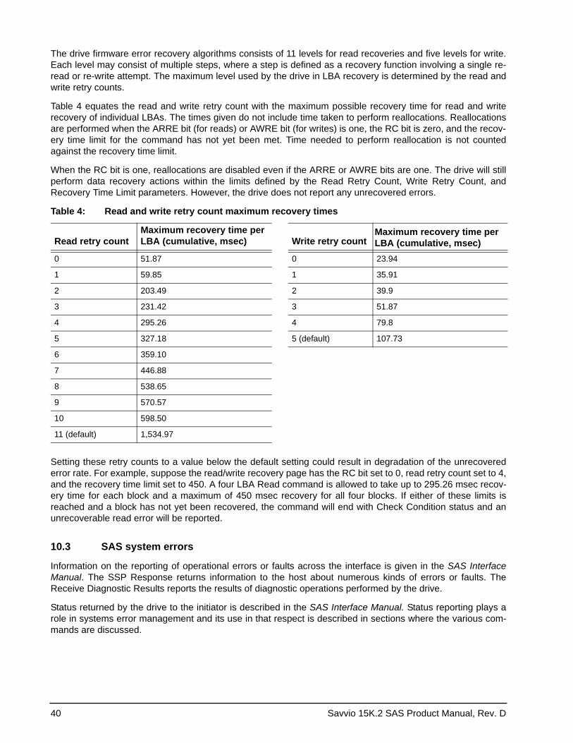
40 Savvio 15K.2 SAS Product Manual, Rev. D
The drive firmware error recovery algorithms consists of 11 levels for read recoveries and five levels for write. Each level may consist of multiple steps, where a step is defined as a recovery function involving a single re-read or re-write attempt. The maximum level used by the drive in LBA recovery is determined by the read and write retry counts.
Table 4 equates the read and write retry count with the maximum possible recovery time for read and write recovery of individual LBAs. The times given do not include time taken to perform reallocations. Reallocations are performed when the ARRE bit (for reads) or AWRE bit (for writes) is one, the RC bit is zero, and the recov-ery time limit for the command has not yet been met. Time needed to perform reallocation is not counted against the recovery time limit.
When the RC bit is one, reallocations are disabled even if the ARRE or AWRE bits are one. The drive will still perform data recovery actions within the limits defined by the Read Retry Count, Write Retry Count, and Recovery Time Limit parameters. However, the drive does not report any unrecovered errors.
Setting these retry counts to a value below the default setting could result in degradation of the unrecovered error rate. For example, suppose the read/write recovery page has the RC bit set to 0, read retry count set to 4, and the recovery time limit set to 450. A four LBA Read command is allowed to take up to 295.26 msec recov-ery time for each block and a maximum of 450 msec recovery for all four blocks. If either of these limits is reached and a block has not yet been recovered, the command will end with Check Condition status and an unrecoverable read error will be reported.
10.3 SAS system errors
Information on the reporting of operational errors or faults across the interface is given in the SAS Interface Manual. The SSP Response returns information to the host about numerous kinds of errors or faults. The Receive Diagnostic Results reports the results of diagnostic operations performed by the drive.
Status returned by the drive to the initiator is described in the SAS Interface Manual. Status reporting plays a role in systems error management and its use in that respect is described in sections where the various com-mands are discussed.
Table 4: Read and write retry count maximum recovery times
Read retry countMaximum recovery time per LBA (cumulative, msec) Write retry count
Maximum recovery time per LBA (cumulative, msec)
0 51.87 0 23.94
1 59.85 1 35.91
2 203.49 2 39.9
3 231.42 3 51.87
4 295.26 4 79.8
5 327.18 5 (default) 107.73
6 359.10
7 446.88
8 538.65
9 570.57
10 598.50
11 (default) 1,534.97
Savvio 15K.2 SAS Product Manual, Rev. D 41
10.4 Background Media Scan
Background Media Scan (BMS) is a self-initiated media scan. BMS is defined in the T10 document SPC-4 available from the T10 committee. BMS performs sequential reads across the entire pack of the media while the drive is idle. In RAID arrays, BMS allows hot spare drives to be scanned for defects prior to being put into service by the host system. On regular duty drives, if the host system makes use of the BMS Log Page, it can avoid placing data in suspect locations on the media. Unreadable and recovered error sites will be logged or reallocated per ARRE/AWRE settings.
With BMS, the host system can consume less power and system overhead by only checking BMS status and results rather than tying up the bus and consuming power in the process of host-initiated media scanning activ-ity.
Since the background scan functions are only done during idle periods, BMS causes a negligible impact to sys-tem performance. The first BMS scan for a newly manufactured drive is performed as quickly as possible to verify the media and protect data by setting the “Start time after idle” to 5ms, all subsequent scans begin after 500ms of idle time. Other features that normally use idle time to function will function normally because BMS functions for bursts of 800ms and then suspends activity for 100ms to allow other background functions to operate.
BMS interrupts immediately to service host commands from the interface bus while performing reads. BMS will complete any BMS-initiated error recovery prior to returning to service host-initiated commands. Overhead associated with a return to host-servicing activity from BMS only impacts the first command that interrupted BMS, this results in a typical delay of about 1 ms.
10.5 Media Pre-Scan
Media Pre-Scan is a feature that allows the drive to repair media errors that would otherwise have been found by the host system during critical data accesses early in the drive’s life. The default setting for Media Pre-Scan is enabled on standard products. Media Pre-Scan checks each write command to determine if the destination LBAs have been scanned by BMS. If the LBAs have been verified, the drive proceeds with the normal write command. If the LBAs have not been verified by BMS, Pre-Scan will convert the write to a write verify to certify that the data was properly written to the disk.
Note. During Pre-Scan write verify commands, write performance may decrease by 50% until Pre-Scan completes. Write performance testing should be performed after Pre-Scan is complete. This may be checked by reading the BMS status.
To expedite the scan of the full pack and subsequently exit from the Pre-Scan period, BMS will begin scanning immediately when the drive goes to idle during the Pre-Scan period. In the event that the drive is in a high transaction traffic environment and is unable to complete a BMS scan within 24 power on hours BMS will dis-able Pre-Scan to restore full performance to the system.
10.6 Deferred Auto-Reallocation
Deferred Auto-Reallocation (DAR) simplifies reallocation algorithms at the system level by allowing the drive to reallocate unreadable locations on a subsequent write command. Sites are marked for DAR during read oper-ations performed by the drive. When a write command is received for an LBA marked for DAR, the auto-reallo-cation process is invoked and attempts to rewrite the data to the original location. If a verification of this rewrite fails, the sector is re-mapped to a spare location.
This is in contrast to the system having to use the Reassign Command to reassign a location that was unread-able and then generate a write command to rewrite the data. DAR is most effective when AWRE and ARRE are enabled—this is the default setting from the Seagate factory. With AWRE and ARRE disabled DAR is unable to reallocate the failing location and will report an error sense code indicating that a write command is being attempted to a previously failing location.
42 Savvio 15K.2 SAS Product Manual, Rev. D
10.7 Idle Read After Write
Idle Read After Write (IRAW) utilizes idle time to verify the integrity of recently written data. During idle periods, no active system requests, the drive reads recently written data from the media and compares it to valid write command data resident in the drives data buffer. Any sectors that fail the comparison result in the invocation of a rewrite and auto-reallocation process. The process attempts to rewrite the data to the original location. If a verification of this rewrite fails, the sector is re-mapped to a spare location.
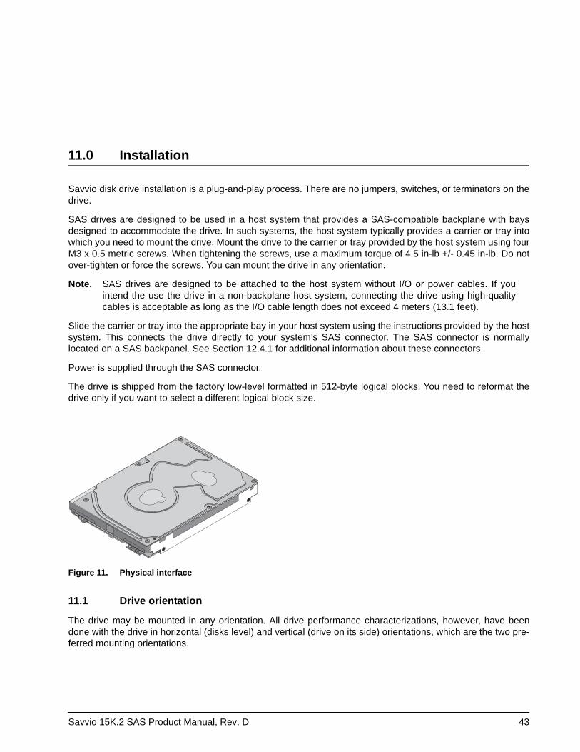
Savvio 15K.2 SAS Product Manual, Rev. D 43
11.0 Installation
Savvio disk drive installation is a plug-and-play process. There are no jumpers, switches, or terminators on the drive.
SAS drives are designed to be used in a host system that provides a SAS-compatible backplane with bays designed to accommodate the drive. In such systems, the host system typically provides a carrier or tray into which you need to mount the drive. Mount the drive to the carrier or tray provided by the host system using four M3 x 0.5 metric screws. When tightening the screws, use a maximum torque of 4.5 in-lb +/- 0.45 in-lb. Do not over-tighten or force the screws. You can mount the drive in any orientation.
Note. SAS drives are designed to be attached to the host system without I/O or power cables. If you intend the use the drive in a non-backplane host system, connecting the drive using high-quality cables is acceptable as long as the I/O cable length does not exceed 4 meters (13.1 feet).
Slide the carrier or tray into the appropriate bay in your host system using the instructions provided by the host system. This connects the drive directly to your system’s SAS connector. The SAS connector is normally located on a SAS backpanel. See Section 12.4.1 for additional information about these connectors.
Power is supplied through the SAS connector.
The drive is shipped from the factory low-level formatted in 512-byte logical blocks. You need to reformat the drive only if you want to select a different logical block size.
Figure 11. Physical interface
11.1 Drive orientation
The drive may be mounted in any orientation. All drive performance characterizations, however, have been done with the drive in horizontal (disks level) and vertical (drive on its side) orientations, which are the two pre-ferred mounting orientations.
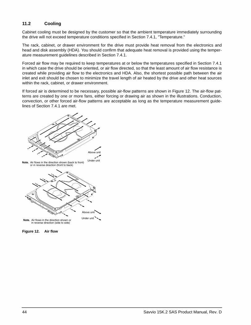
44 Savvio 15K.2 SAS Product Manual, Rev. D
11.2 Cooling
Cabinet cooling must be designed by the customer so that the ambient temperature immediately surrounding the drive will not exceed temperature conditions specified in Section 7.4.1, "Temperature."
The rack, cabinet, or drawer environment for the drive must provide heat removal from the electronics and head and disk assembly (HDA). You should confirm that adequate heat removal is provided using the temper-ature measurement guidelines described in Section 7.4.1.
Forced air flow may be required to keep temperatures at or below the temperatures specified in Section 7.4.1in which case the drive should be oriented, or air flow directed, so that the least amount of air flow resistance is created while providing air flow to the electronics and HDA. Also, the shortest possible path between the air inlet and exit should be chosen to minimize the travel length of air heated by the drive and other heat sources within the rack, cabinet, or drawer environment.
If forced air is determined to be necessary, possible air-flow patterns are shown in Figure 12. The air-flow pat-terns are created by one or more fans, either forcing or drawing air as shown in the illustrations. Conduction, convection, or other forced air-flow patterns are acceptable as long as the temperature measurement guide-lines of Section 7.4.1 are met.
Figure 12. Air flow
Above unit
Under unitNote. Air flows in the direction shown (back to front) or in reverse direction (front to back)
Above unit
Under unitNote. Air flows in the direction shown or in reverse direction (side to side)
Savvio 15K.2 SAS Product Manual, Rev. D 45
11.3 Drive mounting
Mount the drive using the bottom or side mounting holes. If you mount the drive using the bottom holes, ensure that you do not physically distort the drive by attempting to mount it on a stiff, non-flat surface.
The allowable mounting surface stiffness is 80 lb/in (14.0 N/mm). The following equation and paragraph define the allowable mounting surface stiffness:
where K is the mounting surface stiffness (units in lb/in or N/mm) and X is the out-of-plane surface distortion (units in inches or millimeters). The out-of-plane distortion (X) is determined by defining a plane with three of the four mounting points fixed and evaluating the out-of-plane deflection of the fourth mounting point when a known force (F) is applied to the fourth point.
11.4 Grounding
Signal ground (PCBA) and HDA ground are connected together in the drive and cannot be separated by the user. The equipment in which the drive is mounted is connected directly to the HDA and PCBA with no electri-cally isolating shock mounts. If it is desired for the system chassis to not be connected to the HDA/PCBA ground, the systems integrator or user must provide a nonconductive (electrically isolating) method of mount-ing the drive in the host equipment.
Increased radiated emissions may result if you do not provide the maximum surface area ground connection between system ground and drive ground. This is the system designer’s and integrator’s responsibility.
K x X = F < 15lb = 67N
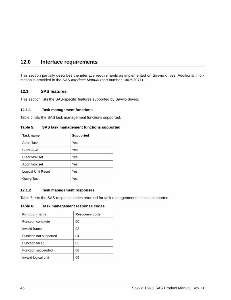
46 Savvio 15K.2 SAS Product Manual, Rev. D
12.0 Interface requirements
This section partially describes the interface requirements as implemented on Savvio drives. Additional infor-mation is provided in the SAS Interface Manual (part number 100293071).
12.1 SAS features
This section lists the SAS-specific features supported by Savvio drives.
12.1.1 Task management functions
Table 5 lists the SAS task management functions supported.
12.1.2 Task management responses
Table 6 lists the SAS response codes returned for task management functions supported.
Table 5: SAS task management functions supported
Task name Supported
Abort Task Yes
Clear ACA Yes
Clear task set Yes
Abort task set Yes
Logical Unit Reset Yes
Query Task Yes
Table 6: Task management response codes
Function name Response code
Function complete 00
Invalid frame 02
Function not supported 04
Function failed 05
Function succeeded 08
Invalid logical unit 09
Savvio 15K.2 SAS Product Manual, Rev. D 47
12.2 Dual port support
Savvio SAS drives have two independent ports. These ports may be connected in the same or different SCSI domains. Each drive port has a unique SAS address.
The two ports have the capability of independent port clocking (e.g. both ports can run at 6Gbit/sec or the first port can run at 6Gbit/sec while the second port runs at 3Gbit/sec.) The supported link rates are 1.5, 3.0, or 6.0 Gbits/sec.
Subject to buffer availability, the Savvio drives support:• Concurrent port transfers—The drive supports receiving COMMAND, TASK management transfers on both
ports at the same time.• Full duplex—The drive supports sending XFER_RDY, DATA and RESPONSE transfers while receiving
frames on both ports.
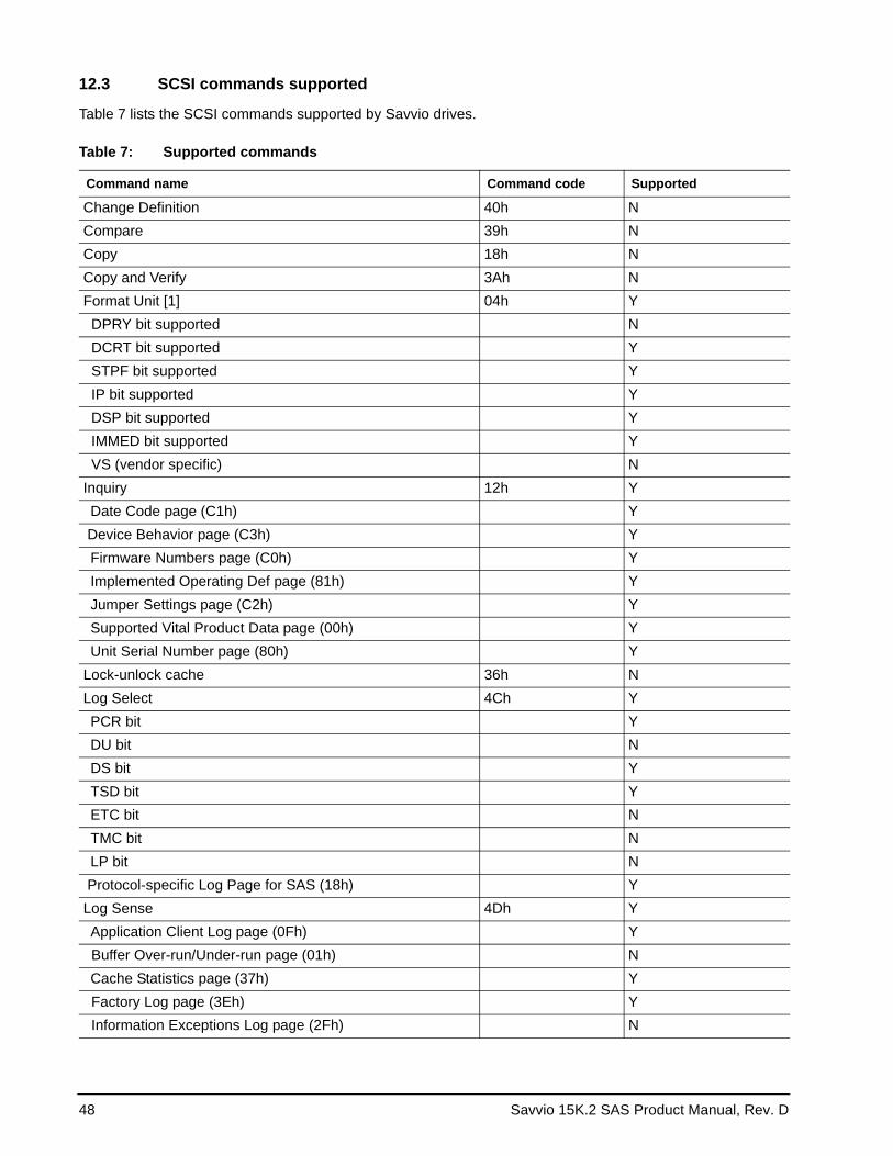
48 Savvio 15K.2 SAS Product Manual, Rev. D
12.3 SCSI commands supported
Table 7 lists the SCSI commands supported by Savvio drives.
Table 7: Supported commands
Command name Command code Supported
Change Definition 40h NCompare 39h NCopy 18h NCopy and Verify 3Ah NFormat Unit [1] 04h Y DPRY bit supported N DCRT bit supported Y STPF bit supported Y IP bit supported Y DSP bit supported Y IMMED bit supported Y VS (vendor specific) NInquiry 12h Y Date Code page (C1h) Y Device Behavior page (C3h) Y Firmware Numbers page (C0h) Y Implemented Operating Def page (81h) Y Jumper Settings page (C2h) Y Supported Vital Product Data page (00h) Y Unit Serial Number page (80h) YLock-unlock cache 36h NLog Select 4Ch Y PCR bit Y DU bit N DS bit Y TSD bit Y ETC bit N TMC bit N LP bit N Protocol-specific Log Page for SAS (18h) YLog Sense 4Dh Y Application Client Log page (0Fh) Y Buffer Over-run/Under-run page (01h) N Cache Statistics page (37h) Y Factory Log page (3Eh) Y Information Exceptions Log page (2Fh) N
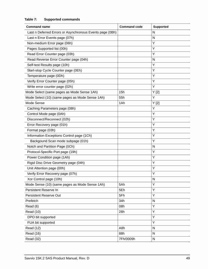
Savvio 15K.2 SAS Product Manual, Rev. D 49
Last n Deferred Errors or Asynchronous Events page (0Bh) N Last n Error Events page (07h) N Non-medium Error page (06h) Y Pages Supported list (00h) Y Read Error Counter page (03h) Y Read Reverse Error Counter page (04h) N Self-test Results page (10h) Y Start-stop Cycle Counter page (0Eh) Y Temperature page (0Dh) Y Verify Error Counter page (05h) Y Write error counter page (02h) YMode Select (same pages as Mode Sense 1Ah) 15h Y [2]Mode Select (10) (same pages as Mode Sense 1Ah) 55h YMode Sense 1Ah Y [2] Caching Parameters page (08h) Y Control Mode page (0Ah) Y Disconnect/Reconnect (02h) Y Error Recovery page (01h) Y Format page (03h) Y Information Exceptions Control page (1Ch) Y Backgound Scan mode subpage (01h) Y Notch and Partition Page (0Ch) N Protocol-Specific Port page (19h) Y Power Condition page (1Ah) Y Rigid Disc Drive Geometry page (04h) Y Unit Attention page (00h) Y Verify Error Recovery page (07h) Y Xor Control page (10h) NMode Sense (10) (same pages as Mode Sense 1Ah) 5Ah YPersistent Reserve In 5Eh YPersistent Reserve Out 5Fh YPrefetch 34h NRead (6) 08h YRead (10) 28h Y DPO bit supported Y FUA bit supported YRead (12) A8h NRead (16) 88h NRead (32) 7Fh/0009h N
Table 7: Supported commands
Command name Command code Supported
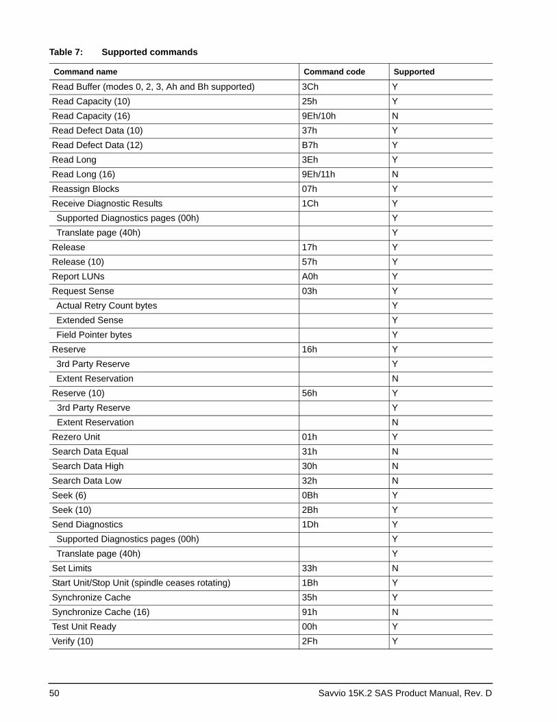
50 Savvio 15K.2 SAS Product Manual, Rev. D
Read Buffer (modes 0, 2, 3, Ah and Bh supported) 3Ch YRead Capacity (10) 25h YRead Capacity (16) 9Eh/10h NRead Defect Data (10) 37h YRead Defect Data (12) B7h YRead Long 3Eh YRead Long (16) 9Eh/11h NReassign Blocks 07h YReceive Diagnostic Results 1Ch Y Supported Diagnostics pages (00h) Y Translate page (40h) YRelease 17h YRelease (10) 57h YReport LUNs A0h YRequest Sense 03h Y Actual Retry Count bytes Y Extended Sense Y Field Pointer bytes YReserve 16h Y 3rd Party Reserve Y Extent Reservation NReserve (10) 56h Y 3rd Party Reserve Y Extent Reservation NRezero Unit 01h YSearch Data Equal 31h NSearch Data High 30h NSearch Data Low 32h NSeek (6) 0Bh YSeek (10) 2Bh YSend Diagnostics 1Dh Y Supported Diagnostics pages (00h) Y Translate page (40h) YSet Limits 33h NStart Unit/Stop Unit (spindle ceases rotating) 1Bh YSynchronize Cache 35h YSynchronize Cache (16) 91h NTest Unit Ready 00h YVerify (10) 2Fh Y
Table 7: Supported commands
Command name Command code Supported
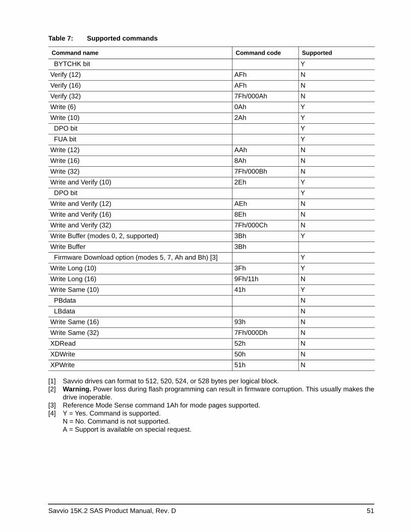
Savvio 15K.2 SAS Product Manual, Rev. D 51
[1] Savvio drives can format to 512, 520, 524, or 528 bytes per logical block.[2] Warning. Power loss during flash programming can result in firmware corruption. This usually makes the
drive inoperable.[3] Reference Mode Sense command 1Ah for mode pages supported.[4] Y = Yes. Command is supported.
N = No. Command is not supported. A = Support is available on special request.
BYTCHK bit YVerify (12) AFh NVerify (16) AFh NVerify (32) 7Fh/000Ah NWrite (6) 0Ah YWrite (10) 2Ah Y DPO bit Y FUA bit YWrite (12) AAh NWrite (16) 8Ah NWrite (32) 7Fh/000Bh NWrite and Verify (10) 2Eh Y DPO bit YWrite and Verify (12) AEh NWrite and Verify (16) 8Eh NWrite and Verify (32) 7Fh/000Ch NWrite Buffer (modes 0, 2, supported) 3Bh YWrite Buffer 3Bh Firmware Download option (modes 5, 7, Ah and Bh) [3] YWrite Long (10) 3Fh YWrite Long (16) 9Fh/11h NWrite Same (10) 41h Y PBdata N LBdata NWrite Same (16) 93h NWrite Same (32) 7Fh/000Dh NXDRead 52h NXDWrite 50h NXPWrite 51h N
Table 7: Supported commands
Command name Command code Supported
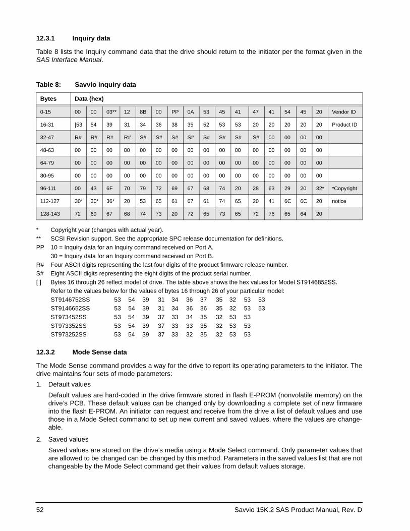
52 Savvio 15K.2 SAS Product Manual, Rev. D
12.3.1 Inquiry data
Table 8 lists the Inquiry command data that the drive should return to the initiator per the format given in the SAS Interface Manual.
Table 8: Savvio inquiry data
Bytes Data (hex)
0-15 00 00 03** 12 8B 00 PP 0A 53 45 41 47 41 54 45 20 Vendor ID
16-31 [53 54 39 31 34 36 38 35 52 53 53 20 20 20 20 20 Product ID
32-47 R# R# R# R# S# S# S# S# S# S# S# S# 00 00 00 00
48-63 00 00 00 00 00 00 00 00 00 00 00 00 00 00 00 00
64-79 00 00 00 00 00 00 00 00 00 00 00 00 00 00 00 00
80-95 00 00 00 00 00 00 00 00 00 00 00 00 00 00 00 00
96-111 00 43 6F 70 79 72 69 67 68 74 20 28 63 29 20 32* *Copyright
112-127 30* 30* 36* 20 53 65 61 67 61 74 65 20 41 6C 6C 20 notice
128-143 72 69 67 68 74 73 20 72 65 73 65 72 76 65 64 20
* Copyright year (changes with actual year).** SCSI Revision support. See the appropriate SPC release documentation for definitions.PP 10 = Inquiry data for an Inquiry command received on Port A.
30 = Inquiry data for an Inquiry command received on Port B.R# Four ASCII digits representing the last four digits of the product firmware release number.S# Eight ASCII digits representing the eight digits of the product serial number.[ ] Bytes 16 through 26 reflect model of drive. The table above shows the hex values for Model ST9146852SS.
Refer to the values below for the values of bytes 16 through 26 of your particular model:ST9146752SS 53 54 39 31 34 36 37 35 32 53 53ST9146652SS 53 54 39 31 34 36 36 35 32 53 53ST973452SS 53 54 39 37 33 34 35 32 53 53ST973352SS 53 54 39 37 33 33 35 32 53 53ST973252SS 53 54 39 37 33 32 35 32 53 53
12.3.2 Mode Sense data
The Mode Sense command provides a way for the drive to report its operating parameters to the initiator. The drive maintains four sets of mode parameters:1. Default values
Default values are hard-coded in the drive firmware stored in flash E-PROM (nonvolatile memory) on the drive’s PCB. These default values can be changed only by downloading a complete set of new firmware into the flash E-PROM. An initiator can request and receive from the drive a list of default values and use those in a Mode Select command to set up new current and saved values, where the values are change-able.
2. Saved valuesSaved values are stored on the drive’s media using a Mode Select command. Only parameter values that are allowed to be changed can be changed by this method. Parameters in the saved values list that are not changeable by the Mode Select command get their values from default values storage.
Savvio 15K.2 SAS Product Manual, Rev. D 53
When power is applied to the drive, it takes saved values from the media and stores them as current val-ues in volatile memory. It is not possible to change the current values (or the saved values) with a Mode Select command before the drive achieves operating speed and is “ready.” An attempt to do so results in a “Check Condition” status.On drives requiring unique saved values, the required unique saved values are stored into the saved val-ues storage location on the media prior to shipping the drive. Some drives may have unique firmware with unique default values also.On standard OEM drives, the saved values are taken from the default values list and stored into the saved values storage location on the media prior to shipping.
3. Current valuesCurrent values are volatile values being used by the drive to control its operation. A Mode Select command can be used to change the values identified as changeable values. Originally, current values are installed from saved or default values after a power on reset, hard reset, or Bus Device Reset message.
4. Changeable valuesChangeable values form a bit mask, stored in nonvolatile memory, that dictates which of the current values and saved values can be changed by a Mode Select command. A one (1) indicates the value can be changed. A zero (0) indicates the value is not changeable. For example, in Table 9, refer to Mode page 81, in the row entitled “CHG.” These are hex numbers representing the changeable values for Mode page 81. Note in columns 5 and 6 (bytes 04 and 05), there is 00h which indicates that in bytes 04 and 05 none of the bits are changeable. Note also that bytes 06, 07, 09, 10, and 11 are not changeable, because those fields are all zeros. In byte 02, hex value FF equates to the binary pattern 11111111. If there is a zero in any bit position in the field, it means that bit is not changeable. Since all of the bits in byte 02 are ones, all of these bits are changeable.The changeable values list can only be changed by downloading new firmware into the flash E-PROM.
Note. Because there are often several different versions of drive control firmware in the total population of drives in the field, the Mode Sense values given in the following tables may not exactly match those of some drives.
The following tables list the values of the data bytes returned by the drive in response to the Mode Sense com-mand pages for SCSI implementation (see the SAS Interface Manual ).
DEF = Default value. Standard OEM drives are shipped configured this way.
CHG = Changeable bits; indicates if default value is changeable.
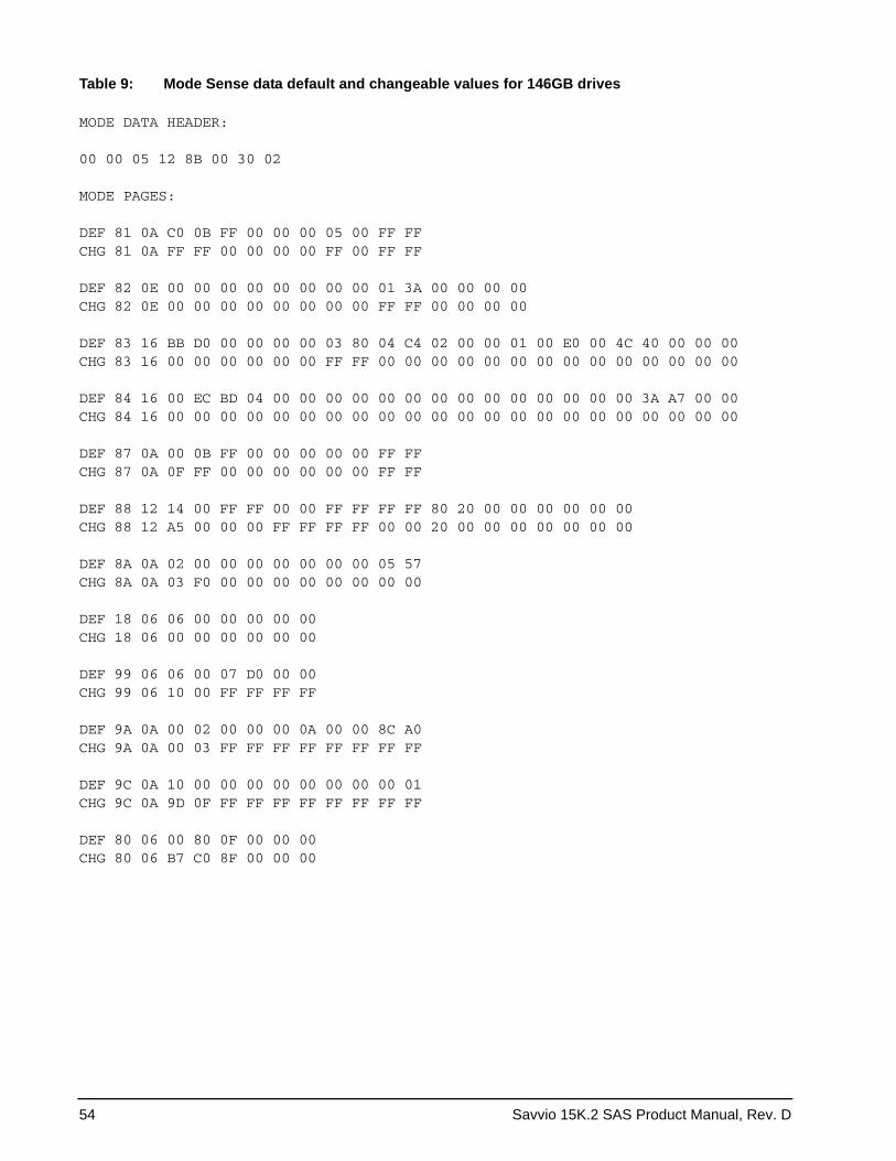
54 Savvio 15K.2 SAS Product Manual, Rev. D
Table 9: Mode Sense data default and changeable values for 146GB drives
MODE DATA HEADER:
00 00 05 12 8B 00 30 02
MODE PAGES:
DEF 81 0A C0 0B FF 00 00 00 05 00 FF FF CHG 81 0A FF FF 00 00 00 00 FF 00 FF FF
DEF 82 0E 00 00 00 00 00 00 00 00 01 3A 00 00 00 00CHG 82 0E 00 00 00 00 00 00 00 00 FF FF 00 00 00 00 DEF 83 16 BB D0 00 00 00 00 03 80 04 C4 02 00 00 01 00 E0 00 4C 40 00 00 00CHG 83 16 00 00 00 00 00 00 FF FF 00 00 00 00 00 00 00 00 00 00 00 00 00 00
DEF 84 16 00 EC BD 04 00 00 00 00 00 00 00 00 00 00 00 00 00 00 3A A7 00 00CHG 84 16 00 00 00 00 00 00 00 00 00 00 00 00 00 00 00 00 00 00 00 00 00 00
DEF 87 0A 00 0B FF 00 00 00 00 00 FF FFCHG 87 0A 0F FF 00 00 00 00 00 00 FF FF
DEF 88 12 14 00 FF FF 00 00 FF FF FF FF 80 20 00 00 00 00 00 00CHG 88 12 A5 00 00 00 FF FF FF FF 00 00 20 00 00 00 00 00 00 00
DEF 8A 0A 02 00 00 00 00 00 00 00 05 57CHG 8A 0A 03 F0 00 00 00 00 00 00 00 00
DEF 18 06 06 00 00 00 00 00CHG 18 06 00 00 00 00 00 00
DEF 99 06 06 00 07 D0 00 00CHG 99 06 10 00 FF FF FF FF
DEF 9A 0A 00 02 00 00 00 0A 00 00 8C A0CHG 9A 0A 00 03 FF FF FF FF FF FF FF FF
DEF 9C 0A 10 00 00 00 00 00 00 00 00 01CHG 9C 0A 9D 0F FF FF FF FF FF FF FF FF
DEF 80 06 00 80 0F 00 00 00 CHG 80 06 B7 C0 8F 00 00 00
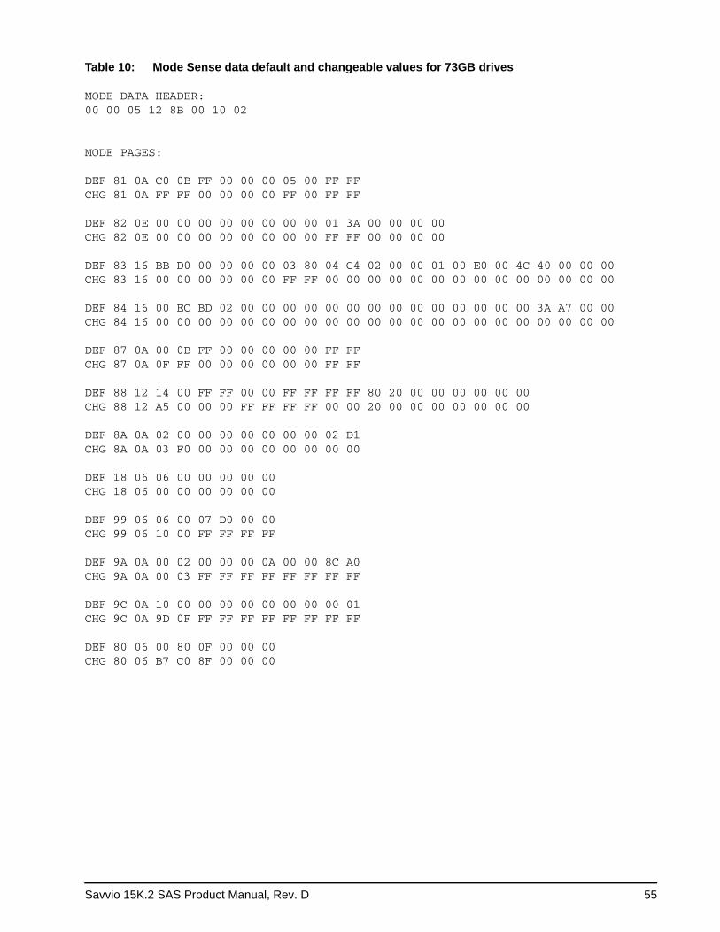
Savvio 15K.2 SAS Product Manual, Rev. D 55
Table 10: Mode Sense data default and changeable values for 73GB drives MODE DATA HEADER:00 00 05 12 8B 00 10 02
MODE PAGES:
DEF 81 0A C0 0B FF 00 00 00 05 00 FF FF CHG 81 0A FF FF 00 00 00 00 FF 00 FF FF
DEF 82 0E 00 00 00 00 00 00 00 00 01 3A 00 00 00 00 CHG 82 0E 00 00 00 00 00 00 00 00 FF FF 00 00 00 00
DEF 83 16 BB D0 00 00 00 00 03 80 04 C4 02 00 00 01 00 E0 00 4C 40 00 00 00 CHG 83 16 00 00 00 00 00 00 FF FF 00 00 00 00 00 00 00 00 00 00 00 00 00 00
DEF 84 16 00 EC BD 02 00 00 00 00 00 00 00 00 00 00 00 00 00 00 3A A7 00 00CHG 84 16 00 00 00 00 00 00 00 00 00 00 00 00 00 00 00 00 00 00 00 00 00 00
DEF 87 0A 00 0B FF 00 00 00 00 00 FF FFCHG 87 0A 0F FF 00 00 00 00 00 00 FF FF
DEF 88 12 14 00 FF FF 00 00 FF FF FF FF 80 20 00 00 00 00 00 00CHG 88 12 A5 00 00 00 FF FF FF FF 00 00 20 00 00 00 00 00 00 00
DEF 8A 0A 02 00 00 00 00 00 00 00 02 D1CHG 8A 0A 03 F0 00 00 00 00 00 00 00 00
DEF 18 06 06 00 00 00 00 00CHG 18 06 00 00 00 00 00 00
DEF 99 06 06 00 07 D0 00 00CHG 99 06 10 00 FF FF FF FF
DEF 9A 0A 00 02 00 00 00 0A 00 00 8C A0CHG 9A 0A 00 03 FF FF FF FF FF FF FF FF
DEF 9C 0A 10 00 00 00 00 00 00 00 00 01CHG 9C 0A 9D 0F FF FF FF FF FF FF FF FF
DEF 80 06 00 80 0F 00 00 00CHG 80 06 B7 C0 8F 00 00 00
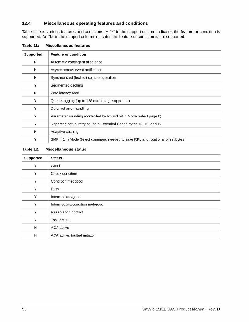
56 Savvio 15K.2 SAS Product Manual, Rev. D
12.4 Miscellaneous operating features and conditions
Table 11 lists various features and conditions. A “Y” in the support column indicates the feature or condition is supported. An “N” in the support column indicates the feature or condition is not supported.
Table 11: Miscellaneous features
Supported Feature or condition
N Automatic contingent allegiance
N Asynchronous event notification
N Synchronized (locked) spindle operation
Y Segmented caching
N Zero latency read
Y Queue tagging (up to 128 queue tags supported)
Y Deferred error handling
Y Parameter rounding (controlled by Round bit in Mode Select page 0)
Y Reporting actual retry count in Extended Sense bytes 15, 16, and 17
N Adaptive caching
Y SMP = 1 in Mode Select command needed to save RPL and rotational offset bytes
Table 12: Miscellaneous status
Supported Status
Y Good
Y Check condition
Y Condition met/good
Y Busy
Y Intermediate/good
Y Intermediate/condition met/good
Y Reservation conflict
Y Task set full
N ACA active
N ACA active, faulted initiator
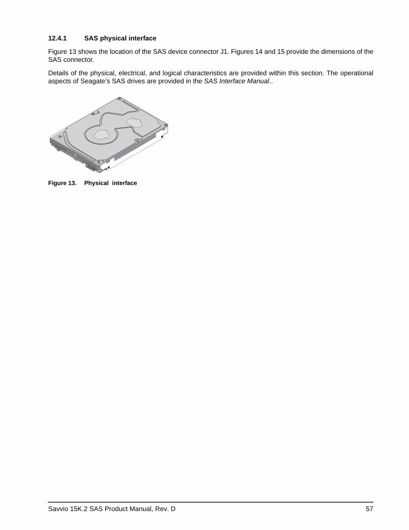
Savvio 15K.2 SAS Product Manual, Rev. D 57
12.4.1 SAS physical interface
Figure 13 shows the location of the SAS device connector J1. Figures 14 and 15 provide the dimensions of the SAS connector.
Details of the physical, electrical, and logical characteristics are provided within this section. The operational aspects of Seagate’s SAS drives are provided in the SAS Interface Manual..
Figure 13. Physical interface
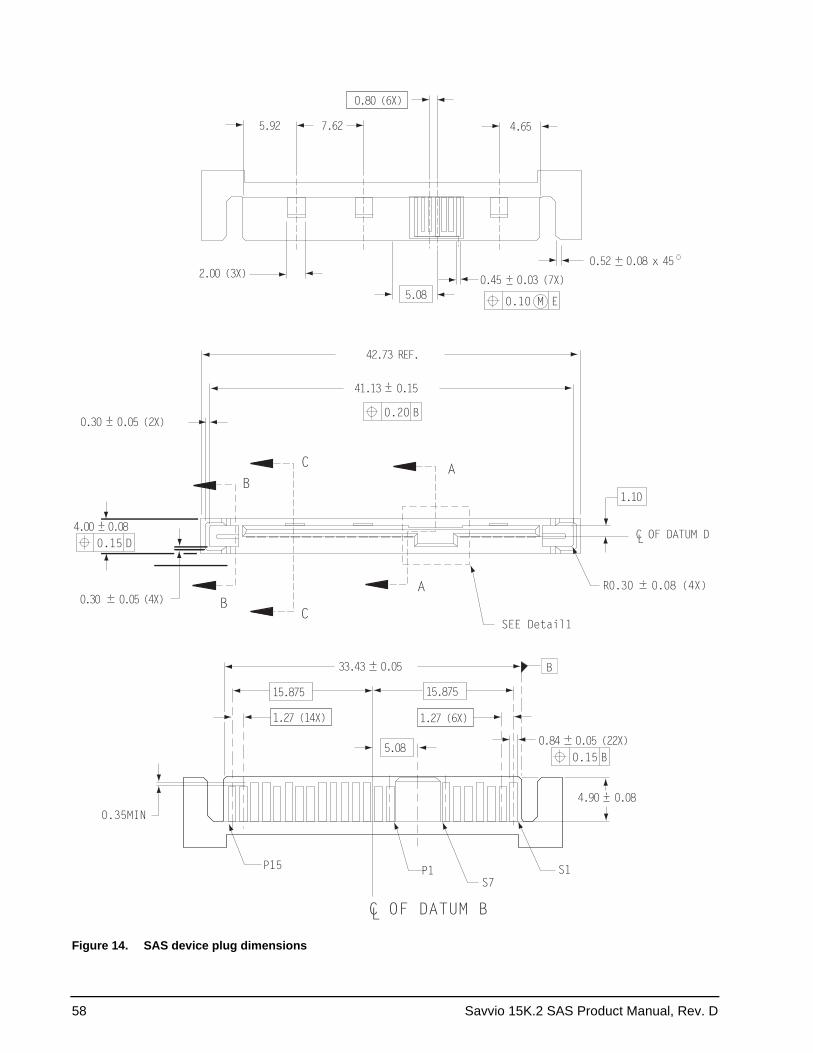
58 Savvio 15K.2 SAS Product Manual, Rev. D
Figure 14. SAS device plug dimensions
C OF DATUM BL
5.08
1.27 (6X)1.27 (14X)
15.875
0.35MIN
15.875
33.43 0.05 B
4.90 0.08
0.84 0.05 (22X)0.15 B
P15 P1S7
S1
SEE Detail1
0.30 0.05 (4X)
4.00 0.080.15 D
0.30 0.05 (2X)
41.13 0.15
B
BC
C A
A
0.20 B
42.73 REF.
C OF DATUM DL
1.10
R0.30 0.08 (4X)
2.00 (3X)
5.080.45 0.03 (7X)
0.10 M E
4.65
0.80 (6X)
7.625.92
0.52 0.08 x 45
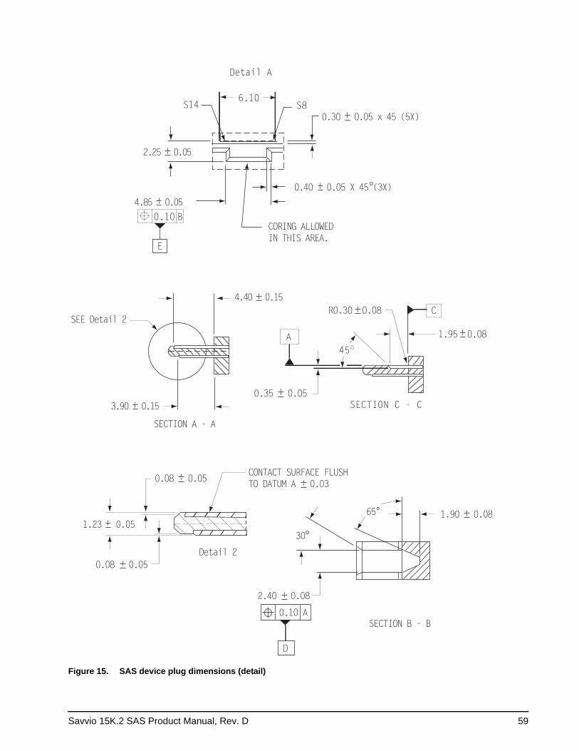
Savvio 15K.2 SAS Product Manual, Rev. D 59
Figure 15. SAS device plug dimensions (detail)
6.10
Detail A
0.30 0.05 x 45 (5X)
0.40 0.05 X 45 (3X)
CORING ALLOWEDIN THIS AREA.
2.25 0.05
4.85 0.050.10 B
E
S14 S8
4.40 0.15
SEE Detail 2
3.90 0.15
SECTION A - A
SECTION C - C
A
0.35 0.05
45
R0.30 0.08 C
1.95 0.08
0.08 0.05
1.23 0.05
0.08 0.05
Detail 2
CONTACT SURFACE FLUSHTO DATUM A 0.03
65
30
1.90 0.08
SECTION B - B
2.40 0.08
0.10 A
D
60 Savvio 15K.2 SAS Product Manual, Rev. D
12.4.2 Physical characteristics
This section defines physical interface connector.
12.4.3 Connector requirements
Contact your preferred connector manufacturer for mating part information. Part numbers for SAS connectors will be provided in a future revision of this publication when production parts are available from major connec-tor manufacturers.
The SAS device connector is illustrated in Figures 14 and 15.
12.4.4 Electrical description
SAS drives use the device connector for:• DC power• SAS interface• Activity LED
This connector is designed to either plug directly into a backpanel or accept cables.
12.4.5 Pin descriptions
This section provides a pin-out of the SAS device and a description of the functions provided by the pins.
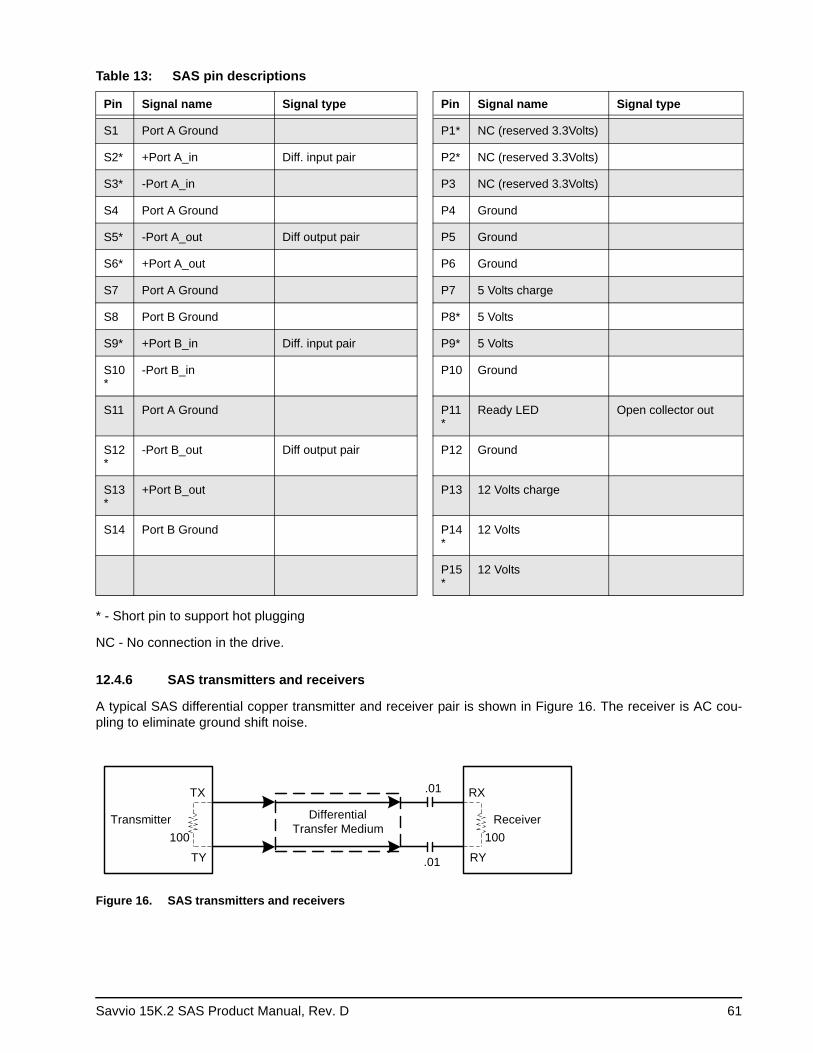
Savvio 15K.2 SAS Product Manual, Rev. D 61
Table 13: SAS pin descriptions
Pin Signal name Signal type Pin Signal name Signal type
S1 Port A Ground P1* NC (reserved 3.3Volts)
S2* +Port A_in Diff. input pair P2* NC (reserved 3.3Volts)
S3* -Port A_in P3 NC (reserved 3.3Volts)
S4 Port A Ground P4 Ground
S5* -Port A_out Diff output pair P5 Ground
S6* +Port A_out P6 Ground
S7 Port A Ground P7 5 Volts charge
S8 Port B Ground P8* 5 Volts
S9* +Port B_in Diff. input pair P9* 5 Volts
S10*
-Port B_in P10 Ground
S11 Port A Ground P11*
Ready LED Open collector out
S12*
-Port B_out Diff output pair P12 Ground
S13*
+Port B_out P13 12 Volts charge
S14 Port B Ground P14*
12 Volts
P15*
12 Volts
* - Short pin to support hot plugging
NC - No connection in the drive.
12.4.6 SAS transmitters and receivers
A typical SAS differential copper transmitter and receiver pair is shown in Figure 16. The receiver is AC cou-pling to eliminate ground shift noise.
Figure 16. SAS transmitters and receivers
ReceiverDifferentialTransfer Medium
.01
.01
100100Transmitter
RX
RY
TX
TY
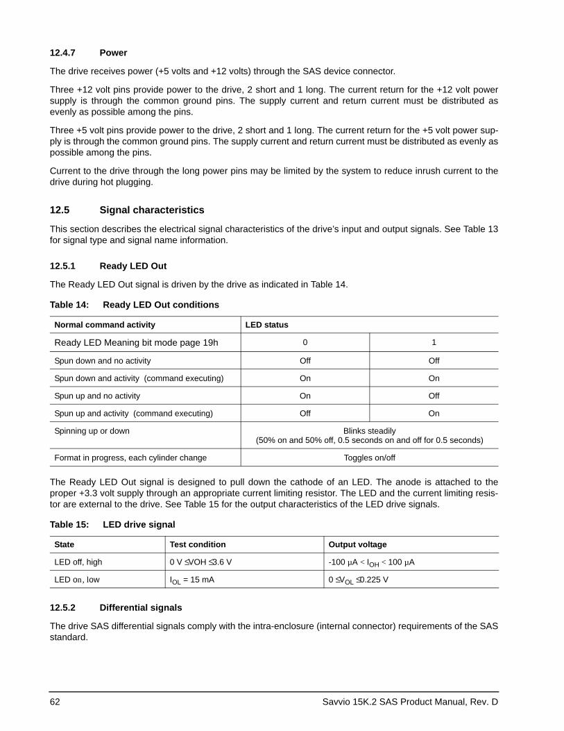
62 Savvio 15K.2 SAS Product Manual, Rev. D
12.4.7 Power
The drive receives power (+5 volts and +12 volts) through the SAS device connector.
Three +12 volt pins provide power to the drive, 2 short and 1 long. The current return for the +12 volt power supply is through the common ground pins. The supply current and return current must be distributed as evenly as possible among the pins.
Three +5 volt pins provide power to the drive, 2 short and 1 long. The current return for the +5 volt power sup-ply is through the common ground pins. The supply current and return current must be distributed as evenly as possible among the pins.
Current to the drive through the long power pins may be limited by the system to reduce inrush current to the drive during hot plugging.
12.5 Signal characteristics
This section describes the electrical signal characteristics of the drive’s input and output signals. See Table 13for signal type and signal name information.
12.5.1 Ready LED Out
The Ready LED Out signal is driven by the drive as indicated in Table 14.
The Ready LED Out signal is designed to pull down the cathode of an LED. The anode is attached to the proper +3.3 volt supply through an appropriate current limiting resistor. The LED and the current limiting resis-tor are external to the drive. See Table 15 for the output characteristics of the LED drive signals.
12.5.2 Differential signals
The drive SAS differential signals comply with the intra-enclosure (internal connector) requirements of the SAS standard.
Table 14: Ready LED Out conditions
Normal command activity LED status
Ready LED Meaning bit mode page 19h 0 1
Spun down and no activity Off Off
Spun down and activity (command executing) On On
Spun up and no activity On Off
Spun up and activity (command executing) Off On
Spinning up or down Blinks steadily(50% on and 50% off, 0.5 seconds on and off for 0.5 seconds)
Format in progress, each cylinder change Toggles on/off
Table 15: LED drive signal
State Test condition Output voltage
LED off, high 0 V ≤ VOH ≤ 3.6 V -100 µA < IOH < 100 µA
LED on, low IOL = 15 mA 0 ≤ VOL ≤ 0.225 V
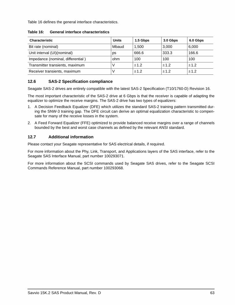
Savvio 15K.2 SAS Product Manual, Rev. D 63
Table 16 defines the general interface characteristics.
12.6 SAS-2 Specification complianceSeagate SAS-2 drives are entirely compatible with the latest SAS-2 Specification (T10/1760-D) Revision 16.
The most important characteristic of the SAS-2 drive at 6 Gbps is that the receiver is capable of adapting the equalizer to optimize the receive margins. The SAS-2 drive has two types of equalizers: 1. A Decision Feedback Equalizer (DFE) which utilizes the standard SAS-2 training pattern transmitted dur-
ing the SNW-3 training gap. The DFE circuit can derive an optimal equalization characteristic to compen-sate for many of the receive losses in the system.
2. A Feed Forward Equalizer (FFE) optimized to provide balanced receive margins over a range of channels bounded by the best and worst case channels as defined by the relevant ANSI standard.
12.7 Additional informationPlease contact your Seagate representative for SAS electrical details, if required.
For more information about the Phy, Link, Transport, and Applications layers of the SAS interface, refer to the Seagate SAS Interface Manual, part number 100293071.
For more information about the SCSI commands used by Seagate SAS drives, refer to the Seagate SCSI Commands Reference Manual, part number 100293068.
Table 16: General interface characteristics
Characteristic Units 1.5 Gbps 3.0 Gbps 6.0 Gbps
Bit rate (nominal) Mbaud 1,500 3,000 6,000Unit interval (UI)(nominal) ps 666.6 333.3 166.6Impedance (nominal, differential ) ohm 100 100 100Transmitter transients, maximum V ± 1.2 ± 1.2 ± 1.2Receiver transients, maximum V ± 1.2 ± 1.2 ± 1.2
64 Savvio 15K.2 SAS Product Manual, Rev. D
Savvio 15K.2 SAS Product Manual, Rev. D 65
Index
Numerics12 volt
pins 625 volt pins 626 Gbps 63
Aabort task set function 46AC coupling 61AC power requirements 21ACA active status 56ACA active, faulted initiator status 56acoustics 33active LED Out signal 62actuator 8
assembly design 6adaptive caching 56Admin SP 36AES-128 data encryption 36air cleanliness 32air flow 29, 44
illustrated 44air inlet 44altitude 30ambient 29ambient temperature 29, 44ANSI documents
SCSI 5Serial Attached SCSI 5
asynchronous event notification 56audible noise 3auto write and read reallocation
programmable 7automatic contingent allegiance 56average idle current 22, 23average rotational latency 10
BBackground Media Scan 41backpanel 60Band 0 37BandMasterX 37BMS 41buffer
data 7space 12
busy status 56
Ccache operation 12
cache segments 12caching write data 13Canadian Department of Communications 3capacity
unformatted 10case temperature 29CBC 36CE Marking 4check condition status 56Cipher Block Chaining 36class B limit 3clear ACA function 46clear task set function 46commands supported 48condensation 29condition met/good status 56connector
illustrated 60requirements 60
continuous vibration 32cooling 44CRC
error 15Cryptographic erase 38Current profiles 25customer service 20
DDAR 41Data Bands 37data bands 36data block size
modifing the 8Data encryption 36Data Encryption Key 36data heads
read/write 10data rate
internal 10data transfer rate 11DC power 60
requirements 21Decision Feedback Equalizer 63decrypt 36default MSID password 37defect and error management 39defects 39Deferred Auto-Reallocation 41deferred error handling 56DEK 36description 6DFE 63dimensions 34disc rotation speed 10drive 32
66 Savvio 15K.2 SAS Product Manual, Rev. D
drive characteristics 10Drive Locking 37drive mounting 34, 45drive select 60dual port support 47
Eelectrical
description of connector 60signal characteristics 62specifications 21
electromagnetic compatibility 3Electromagnetic Compatibility (EMC) 4Electromagnetic Compatibility control Regulation 4electromagnetic susceptibility 33EMI requirements 3encryption engine 36encryption key 37environment 44environmental
limits 29requirements 14
environmental control 32EraseMaster 37error
management 39rates 14
errors 39
FFCC rules and regulations 3features 7
interface 46Federal Information Processing Standard 35feed forward equalizer 63FFE 63FIPS 35firmware 7
corruption 51firmware download port 37flawed sector reallocation 7Format command execution time 11function
complete, code 00 46not supported, code 05 46reject, code 04 46
GGlobal Data Band 37Good status 56gradient 29ground shift noise 61grounding 45
HHDA 44, 45head and disc assembly (HDA) 6head and disc assembly. See HDAheads
read/write data 10heat removal 44heat source 44host equipment 45hot plugging the drive 15humidity 29humidity limits 29
IIdle Read After Write 42inquiry data 52installation 43
guide 5interface
commands supported 48error rate 14errors 15illustrated 57physical 57requirements 46
intermediate/condition met/good status 56intermediate/good status 56internal data rate 10internal defects/errors 39internal drive characteristics 10IRAW 42
Jjumpers 43
KKCC 4Korean Communications Commission 4
Llatency
average rotational 10Locking SP 36, 37LockOnReset 37logical block address 12logical block reallocation scheme 7logical block size 7, 11logical segments 12
Mmaintenance 14Makers Secure ID 36
Savvio 15K.2 SAS Product Manual, Rev. D 67
maximum delayed motor start 22, 23maximum start current 22, 23mean time between failure. See MTBFmedia description 7Media Pre-Scan 41miscellaneous feature support
Adaptive caching 56Asynchronous event notification 56Automatic contingent allegiance 56Deferred error handling 56Parameter rounding 56Queue tagging 56Reporting actual retry count 56Segmented caching 56SMP = 1 in Mode Select command 56Synchronized (locked) spindle operation 56Zero latency read 56
miscellaneous status supportACA active 56ACA active, faulted initiator 56Busy 56Check condition 56Condition met/good 56Good 56Intermediate/condition met/good 56Intermediate/good 56Reservation conflict 56Task set full 56
miscorrected media data 14Mode sense
data, table 52, 54mounting 45
holes 45orientations 43
mounting configuration 34MSID 36, 37MTBF 14, 15, 29
NNational Institute of Standards and Technology 35NIST 35noise
audible 3noise immunity 24non-operating 29, 30, 32
temperature 29non-operating vibration 32
Ooffice environment 32operating 29, 30, 32option selection 60orientation 30out-of-plane distortion 45
Ppackage size 31package test specification 5packaged 31parameter rounding 56password 36, 37passwords 37PCBA 45peak bits per inch 10peak operating current 22, 23peak-to-peak measurements 24performance characteristics
detailed 10general 11
performance degradation 30performance highlights 8physical damage 32physical interface 57physical specifications 21pin descriptions 60power 62
dissipation 27requirements, AC 21requirements, DC 21sequencing 24
power distribution 3PowerCycle 37prefetch/multi-segmented cache control 12preventive maintenance 14protection of data at rest 36
Qqueue tagging 56
Rradio interference regulations 3Random number generator 37RCD bit 12read error rates 14, 39read/write data heads 10receivers 61recommended mounting 31Recoverable Errors 14recovered media data 14reference
documents 5relative humidity 29reliability 8
specifications 14reliability and service 15repair and return information 20reporting actual retry count 56reservation conflict status 56resonance 30
68 Savvio 15K.2 SAS Product Manual, Rev. D
return information 20RNG 37rotation speed 10
Ssafety 3SAS
interface 60physical interface 57task management functions 46
SAS documents 5SAS Interface Manual 3, 5SAS-2 Specification 63SCSI interface
commands supported 48Secure ID 36security partitions 36Security Protocol In 36Security Protocol Out 36seek error
defined 15rate 14
seek performance characteristics 10seek time
average typical 10full stroke typical 10single track typical 10
segmented caching 56self-encrypting drives 36Self-Monitoring Analysis and Reporting Technology
8, 16Serial Attached SCSI (SAS) Interface Manual 2shielding 3shipping 20shipping container 29shock 30
and vibration 30shock mount 45SID 36signal
characteristics 62single-unit shipping pack kit 9SMART 8, 16SMP = 1 in Mode Select command 56SNW-3 training gap 63Specification 63spindle brake 7standards 3start/stop time 11support services 1surface stiffness
allowable for non-flat surface 45switches 43synchronized spindle
operation 56
system chassis 45
Ttask management functions 46
Abort task set 46Clear ACA 46Clear task set 46terminate task 46
task management response codes 46Function complete 00 46Function not supported 05 46Function reject 04 46
task set full status 56TCG 36technical support services 1temperature 29, 44
ambient 29case 29gradient 29limits 29non-operating 29regulation 3See also cooling
terminate task function 46terminators 43tracks per inch 10tracks per surface 10transmitters 61transporting the drive 20Trusted Computing Group 36
Uunformatted 8Unrecoverable Errors 14unrecovered media data 14
Vvibration 30, 32
Wwarranty 20
Zzero latency read 56zone bit recording (ZBR) 7


Seagate Technology LLC920 Disc Drive, Scotts Valley, California 95066-4544, USAPublication Number: 100516230, Rev. D