Embed Size (px)
Citation preview

Save up to 30% in Energy Extracting Part of the Sensible Heat
For Steam applications ranging up to:
1,100°F (593°C)0-2,600 psi (179 bar)

VELAN COMPANY PROFILE
CONTENTSManufacturing Plants ..........................................1Principles of Operation.................................... 2, 3How it Works ......................................................4, 5Forged Universal Bimetallic Steam Traps Types TS, TSF & SF .......................................... 6, 7Universal Bimetallic Steam Traps Type SSF ............................................................ 8, 9Forged HP/HT Steam TrapsType N ............................................................ 10, 11Hermetically Sealed Steam TrapsType Q250 ...................................................... 12, 13High Capacity Piston Operated Steam Traps Type SPF & SP....................... 14, 15Piping King Package Units .......................... 16-19Monovalve Float Bimetallic Steam TrapsType MFT & MFTS ....................................... 20-22Space Heating Steam Traps Type ACF ........... 23Thermodynamic Steam TrapsType HPTD, PTD & VTS ............................... 24, 25Compressed Air Drain Traps Type MFA & MFAS ...................................... 26, 27Strainers............................................................... 28Accessories..........................................................29Comparison of Principles of Operation ...........31Selection - Sizing ................................................32How to Order ....................................................... 33
Velan is one of the world's leading manufacturers of industrial valves,supplying forged and cast steel gate, globe, check, ball, butterfly, knife gateand engineered severe service valves for critical applications in power,chemical and petrochemical, oil and gas, pulp and paper, mining, marine,cryogenic and general construction industries.Founded in 1950, Velan earned a reputation for excellence as a major supplierof forged valves to nuclear power plants and the U.S. Navy. Velan haspioneered many innovative valve designs, emphasizing quality, safety, ease of operation, low emissions, simple in-line maintenance and long cycle life.Velan’s 21 product lines are manufactured in 12 specialized manufacturingplants, including six in Canada and U.S.A., three in Europe, and three in Asia.We have 1,500 employees, 75% of whom are located in our North Americanoperations.
GENERAL INFORMATIONTel: 44-116 269-5172Fax: 44-116 [email protected]
Visit the Velan website at www.velan.com for an updated contact list.Velan has sales offices and distributors located worldwide.
NOTE: The material in this catalog is for general information. For specific performance data and proper material selection, consult yourVelan representative. Although every attempt has been made to ensure that the information contained in this catalog is correct, Velan reserves the right to change designs, materials or specifications without notice.
MONTREAL, CANADA 115,000 sq. ft. (10,683 m2) 3 –24” (80 –600 mm) butterfly, 3⁄8 –4” (10 –100 mm) metal & resilient seated ball valves
HEAD OFFICE & PLANT 5
U.S.A.VELAN VALVE CORPORATIONPLANT 394 Avenue CWilliston, VT 05495-9732Tel: (802) 863-2562Fax: (802) 862-4014
ENGLANDVELAN VALVES LTD.Unit 1, Pinfold RoadLakeside Business ParkThurmaston Leicester LE4 8AS Tel: 44-116 269-5172Fax: 44-116 269-3695
FRANCEVELAN S.A.S90, rue Challemel LacourF 69 367 Lyon Cedex 7 Tel: (33) 4 78 61 67 00Fax: (33) 4 78 72 12 18
PORTUGALVELAN VÁLVULASINDUSTRIAIS, LDA.Av. Ary dos Santos1679-018 FamoesTel: (351-21) 934-7800Fax: (351-21) 934-7809
TAIWANVELAN-VALVACP.O. Box 2020Taichung, TaiwanR.O.C.Tel: (04) 2792649Fax: (886) 42750855
KOREAVELAN LTD.1060-4 Shingil-DongAnsan City, Kyunggi-do 425-833Tel: (82) 31-491-2811Fax: (82) 31-491-2813
CANADAVELAN INC.HEAD OFFICE & PLANT 57007 Côte de LiesseMontreal, QC H4T 1G2Tel: (514) 748-7743Fax: (514) 748-8635
PLANT 12125 Ward AvenueMontreal, QC H4M 1T6Tel: (514) 748-7743Fax: (514) 748-8635
PLANT 2 / 7550 McArthur Ave.Montreal, QC H4T 1X8Tel: (514) 748-7743Fax: (514) 341-3032
PLANT 4 / 61010 Cowie StreetGranby, QC J2J 1E7Tel: (450) 378-2305Fax: (450) 378-6865
PROQUIP835 Fourth LineOakville, ON L6L 5B8Tel: (905) 842-1721Fax: (905) 849-0923
GERMANYVELAN GmbH Daimlerstrasse 8 D-47877 Willich Tel: (49) 2154/4938-00Fax: (49) 2154/4938-99
MANUFACTURING LOCATIONS DISTRIBUTION CENTERS U.S.A.VELCAL537 Stone Road, Unit "A"Benicia, CA 94510Tel: (707) 745-4507Fax: (707) 745-4708
VELEAST605 Commerce Park Drive SEMarietta, GA 30060Tel: (770) 420-2010Fax: (707) 420-7063
THE ORIGINAL VELAN STEAM TRAPVelan is pleased to announce that we havereacquired the Velan universal steam trapline produced for 15 years by Plenty SteamProducts. This comprehensive range of steamtraps is based on a unique design that wasdeveloped and patented by A.K. Velan,President and CEO of Velan Inc., and is nowcopied by major steam trap manufacturers.Once again, you can trust Velan to supplyhigh quality steam traps for virtually all ofyour condensate drainage applications.

MANUFACTURING PLANTS AROUND THE WORLD
ANSAN CITY, SOUTH KOREA Plant 1 30,000 sq. ft. (2,800 m2)components and 2–4” (50–100 mm) cast steel valves, ISO 9002
LISBON, PORTUGAL 60,000 sq. ft. (5,600 m2) ISO 90022–12” (50–300 mm) cast steel gate, globe and check valves
LYON, FRANCE 160,000 sq. ft. (14,900 m2) 1⁄4 –40” (8–1,000 mm)forged and cast steel gate, globe and butterfly valves, ISO 9001
WILLISTON, VERMONT, U.S.A. 155,000 sq. ft. (14,400 m2)2 –24” (50–600 mm) forged and cast steel gate, globe and checkvalves, ASME ‘N’ stamp, ISO 9001
MONTREAL, CANADA 109,000 sq. ft. (10,126 m2) 1⁄4 –4” (8 –100 mm) forged gate, globe & check valves, ASME ‘N’ stamp, ISO 9001
ANSAN CITY, SOUTH KOREA Plant 2 65,000 sq. ft. (5,800 m2) 6–12” (150 –300 mm) cast steel gate, globe, check, ball and knife gate valves, ISO 9002
TAICHUNG, TAIWAN Velan-Valvac 20,000 sq. ft. (1,840 m2)1⁄4 –2” (8–50 mm) ball valves, ISO 9002
TORONTO, CANADA Velan-Proquip 41,000 sq. ft. (3,800 m2) 2– 48” (50 – 1200 mm) wafer check valves1⁄2 – 24” (15 – 600 mm) clamp joint connectors, ISO 9001
MONTREAL, CANADA 170,000 sq. ft. (15,800 m2) 2 –60” (50–1500 mm)forged and cast steel gate, globe, check, ball, knife and butterfly valves 26–36” (650–700 mm) ASME ‘N’ stamp, ISO 9001
GRANBY, CANADA 186,500 sq. ft. (17,325 m2)2–12” (50 –300 mm) cast steel gate and check valves, 1⁄4 –12” (8–300 mm) ball valves, ISO 9001
PLANT 1
PLANT 2 & 7
PLANT 4 & 6
PLANT 3
WILLICH, GERMANY 12,000 sq. ft. (1,115 m2) ISO 9002
LEICESTER, ENGLAND 14,000 sq. ft. (1,300 m2) ISO 9002, steam traps, 3⁄8–2” (10–50 mm) bonnetless globe valves 1⁄2 – 2” (15 – 50 mm)
1

The force of line pressure acting on the valveball holds it open when condensate or air is inthe trap. Line pressure, valve and orificediameter determine this force. For a 1/2”(12.7 mm) orifice at 150 psi (10.3 bar) linepressure develops a force of 30 lb (134 N). To close the valve on steam the bimetallicelement must develop a pull of at least 35 lb(156 N) with three segments. The patentedVelan multi-segment design was developed sothat the thermal pull of the bimetal elementwould closely follow the saturated steam curveand use only the portion of the elementrequired to overcome the opening force atsaturated steam temperature.
A non-segmented bimetallic element wouldhave a straight-line characteristic and the trapwould only react to large temperaturedifferentials, whereas the Velan segmentedelement automatically compensates for anypressure condition within its range, andmaintains the sensitivity to release condensateat below steam temperature without loss ofsteam.
Chart 1 illustrates the truly universal operatingprinciple behind the Velan steam trap. Eachsegment acts consecutively, covering thecomplete operating pressure range withoutadjustment or orifice change. With a singleelement the temperature differential to openthe steam trap would be BC1 (66°F/37°C)instead of BC (8°F/4.4°C) and the requiredclosing force would be BA1 (20 lb/90 N) insteadof BA (5 lb/22 N).
THE CLOSING FORCE OF THE BIMETALLIC ELEMENTS FOLLOWS THE SATURATED STEAM CURVE
WHAT IS BIMETAL?
● Bimetal is a compositemetal comprising two or more metallic layers with differentcoefficients ofexpansion, whichchanges curvature when subjected to heat.
PRINCIPLES OF OPERATION
The Original “Universal” Bimetal Principle
Actuates Velan Steam Traps
1 2 3 4
212
A
BCC1
A1
200 250 300 350 400 440
100 150 200 225
287
Steam Temperature142
0
50
100
134
156
200
250
300
0
10
20
30
40
50
60
70
35
0
50
100
150
200
250
300
350
Ste
am P
ress
ure
bar
5
10
15
20
25
0
Multielement
Single element
Pull
of B
imet
al
psi
lbN
Velan Steam Trapsuse a bimetal ofhigh tensilestrength, stable athigh temperaturewith deflectionlimited to 600°F(315°C) to preventover-stressing onsuper-heatedsteam service.
1. Free deflection up to 212°F (100°C)2. One segment pulling 0-40 psi (0-2.8 bar) up to 287°F (142°C)3. Two segments pulling 40-120 psi (2.28-8.3 bar) up to 350°F (177°C)4. Three segments pulling 120-350 psi (8.3-24 bar) up to 440°F (227°C)
2
Chart 1 Operating Principle of Velan Steam Traps

UNIVERSAL STEAM TRAPPRINCIPLE
● Chart 2 illustrates the bimetalclosing force developed atsaturated temperature in relationto the line pressure tending toopen the valve. The gradualincrease in force, following thesteam curve, is a function of thepatented segmentation principle ofthe element. The delicate balanceof opening and closing forcesexists in all pressure ranges suchas 0-200, 0-350, 0-600, 0-1500, 500-2500 psi (0-14, 0-21, 0-41, 0-103, 35-172 bar), and producescomplete universal operationthroughout the pressure rangewithout adjustment or orificechange. See page 4 for more details.
FLOAT BIMETALLICPRINCIPLE
● Chart 3 illustrates the operation ofthe combination of a bimetal andfloat element utilized in thefloat/bimetallic series. In thisprinciple, the bimetal is used toclose the valve at saturatedtemperature or release cool air in the system. However a smallaccumulation of condensate in the trap body lifts the float and opens the discharge valve.No temperature depression isrequired for this process and, as a result, the characteristic isidentical to the saturated steamcurve. The steam trap shuts off in the presence of steam andopens at once in the presence of condensate even at saturatedsteam temperature. See page 5 for more details.
The Velan Patented Bimetal Principle
as Applied to Meet Various Requirements
PRINCIPLES OF OPERATION
0
50
100
150
200
250
300
0
10
20
30
40
50
60
ElementClosingForces
Element 1
Element 1 & 2
Element 1
Element 1 & 2
Element 1, 2 & 3
– 3– 2– 1
lb
SteamPressure
psi
10
5
15
20
bar
250
200
100
50
0
N
150
SteamPressure
0
20
40
ElementClosingForces
0
100
200
0
50
100
150
200
200 250 300 350 40015010065
Steam Temperature18 50 100 150 200
200 300 40010065
Steam Temperature18 50 100 150 200
psi
bar
lb N
0
0
5
10
15
30
10Saturated
Steam Curve
Saturated
Steam Curve
Saturated
Steam Curve
Saturated
Steam Curve
Chart 2 The patented Multi-element Principle.
Chart 3 The patented Multi-element Principle combined with a float.
3

HOW IT WORKS
THE 4 PURPOSE VALVE AND ITS FUNCTION IN THE VELAN UNIVERSAL BIMETALLIC STEAM TRAP
CHECK VALVE ACTION
Back pressure in the discharge pipe, a sudden drop insteam pressure a rapid fluctuation or discharging tooverhead lines causes back flow of condensate.
TWO STEP DRAINAGE
PressureActionOn Full
Valve Area
TRAPPING DRAINING
Closing Force
PressureBalancedValve Closed
Pressure CracksValve andReleases Flow
Pressure Opens Valve CompletelyActing On FullValve Area
Opening Force PressureAction
On Orifice
Unbalanced Pressure
II STEPI STEPActing ValveArea
ThermalPull
DifferentialPressure
4
When steam condenses into water, the thermal pull of thebimetal is gradually reduced until the line pressure on thevalve releases it from the valve seat and allows conden-
sate to be discharged. This is the first step in thesmooth and quick openingof the valve, without noiseor violent action. When the flow is released, theunbalanced pressure actson the full valve area. The force to overcome thethermal pull increases andopens the orifice to fullcapacity.
To prevent this possibleback flow or condensateentering the equipment notin service, separate checkvalves have to be installedas near to the trap aspossible. In Velan SteamTraps the discharge valve in the trap acts as a checkvalve providing full backflow control.
FAST WARM UP The discharge valve is open, allowing air and cold waterto be discharged rapidly. The period of waiting to start a process is reduced to minutes – there is no air binding,
POSITIVE TRAPPING Incoming steam causes the bimetal to deflect. This thermal pull of the bimetal element acts on the valvestem overcoming the steam pressure closing the valve.The ball valve is pulled tightly on to water-logging or steam
locking to delay equipmentwarm up.
Actual tests show that up to21/2 hours may be saved oneach “warm-up” becauseVelan Steam Traps have amuch greater ventingcapacity than other traps,due to large orifice.
its seat preventing weepingand loss of live steam. The thermal pull increasesor decreases as a functionof temperature, in thesame relation as thetemperature and pressureof the saturated steam. The same element can beused for varying steampressures within widepressure ranges.

HOW IT WORKS
THE 4 PURPOSE VALVE AND ITS FUNCTION IN THE VELANPISTON OPERATED & THE MONOVALVE FLOAT BIMETALLIC
STEAM TRAP
5
CONDENSATE DISCHARGE
When condensate andair collect in the trapbody, the bimetal forceis reduced, line pressureopens the pilot valve,pressurizing the pistonchamber and forcing themain valve open againstline pressure by virtueof the greater pistonarea.
If condensate builds up in the trap body, the float becomesbuoyant, and opens the valve to unrestricted flow. Condensate even at steam temperature is discharged atthe same rate as it reachesthe trap. No air binding or water logging irrespective of adverse conditions. The trap drains by gravity and will not freeze.
Excess back pressure, adrop in line pressure, ordischarging to overheadreturn lines, can cause areverse flow ofcondensate through thetrap. Normally separatecheck valves are requiredto prevent this occurrence. The Velan type SP main discharge valve also works as a temporary piston check valve and prevents back flow.
When pressure is off, equipment discharging to acommon return, or where condensate is returned to overhead lines, a check valve is required to prevent reverse flow through the trap. The free-floating MFT mechanism shuts immediately the reverse flow and no additional device is required.
FAST WARM UP Cool air and condensatefrom the system isdischarged through thelarge main valve orificeactuated by the piston,which is held open byit’s own weight whencold. As line pressurebuilds up pressure above the piston keeps the valve open at maximum discharge until the system is completely purged of air and condensate.
Clearing air and moisture from a coldsystem rapidly reduces warm-up time and increases production. Other float traps must have a separate air venting facility while the Velan MFT utilizes the large main orifice for the fastest warm-up time of any comparable sized float trap.
POSITIVE TRAPPING Incoming steamcontacting the bimetalelement closes the pilotvalve, thereby reducingthe pressure acting onthe piston. Line pressurebelow the main valvecloses it tightly butsmoothly, due to thepartial pressureremaining in the pistonchamber.
When condensate is discharged, the float mechanism rests on the trap body. The bimetal element alone, closes the valve with thermal power developed by incoming steam. The bimetal element is a function of the saturated steam curve, therefore operates efficiently at any pressure within it’s range.
CHECK VALVE ACTION
PISTON OPERATED MONOVALVE FLOAT BIMETALLIC
Pilot Valve
Piston Main Valve

VELAN FORGED UNIVERSAL BIMETALLIC STEAM TRAPS
6
A L GF
I
H
D
BCE
JK
Type TS, TSF & SF with Cage Unit, Air Vent, Check Valve, Strainer & OptionalTemperature Controller
TYPE TS, TSF & SF DESIGN FEATURES
● Forged valve body and cover (A, B)offer the advantages of high strength, structural integrity and reliability that make it an ideal choice for steam service.
● Stainless Steel Trim
● Cage Unit (K, C, J, G, I)The advanced cage unit design in Velan Steam Traps combines a bimetal element, hardened Rc 58 min. ball valve and a Stellited seat area all in one factory-tested assembly. Replacement of all wearing parts can be achieved in less than two minutes, with the trap remaining in-line.
● Stellited SeatsAll Velan valve seats are Stellite faced to increase their resistance to the high degree of wear through velocity of flow, dirt and scale.
● Integral strainer (F)Stainless steel screens are integral in all threemodels to protect the trap operating mechanismfrom damage by dirt or scale. No extra fittings orinstallation costs are required. Free strainer areaminimum 5 to 1. Perforation is 0.031" (0.8 mm).
● Universal operationThe individual segments of the bimetallic elementact consecutively, developing forces in closerelation to the saturated steam curve. Thispermits sensitive, efficient trap operation at all
Type TS
pressures from 1 psi to maximum, without orificechange or adjustment.
● Silent operation – no violent line shocks.
● Positive closingEvery Velan steam trap closes tightly on saturatedsteam temperature. Positive closing for longperiods on dry superheated steam has enormousadvantages in power plant and marine service.
● All-position operation simplifies piping layout.
● FreezeproofVelan traps do not require a reservoir of primingwater in the body to operate. When installedvertically with inlet on top, they drain completelywhen cold, and are freezeproof without insulation.
● Positive condensate drainage for process work.
● Optional Temperature controller on SFAn ingenious device that allows adjustment of factory setting under full steam pressure. Condensate discharge temperature can be increased or decreased to meet the specific requirements of any process application. Up to 30% of energy can be saved by extracting the sensible heat of steam.
● Other options include:NPT blow down plug, Piping King Units complete with valving.
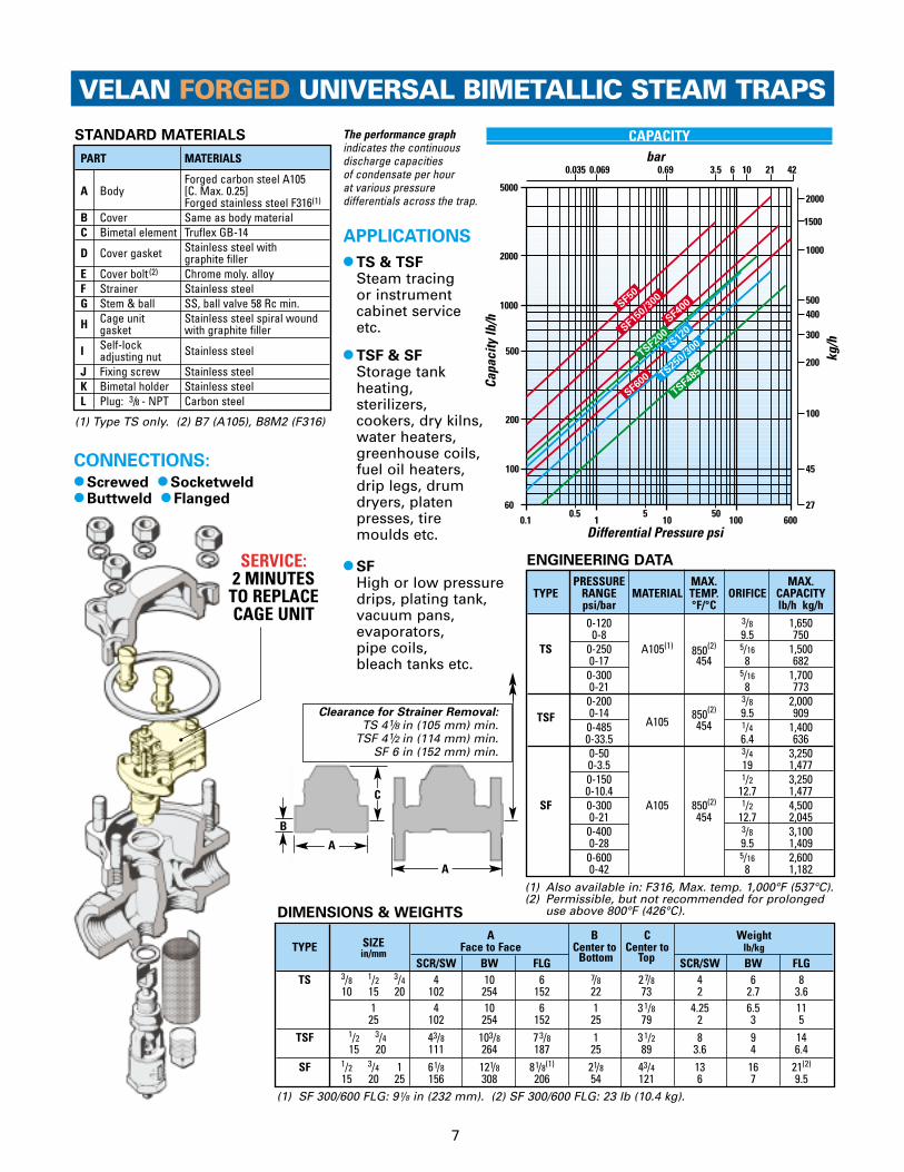
CAPACITYThe performance graph indicates the continuousdischarge capacities of condensate per hour at various pressuredifferentials across the trap.
0.10.5
15
1050
100 600
100
60
200
500
1000
2000
5000
27
45
100
200
300
400500
1000
1500
2000
0.035 0.069 0.69 3.5 6 10 21 42bar
Capa
city
lb/h
Differential Pressure psi
kg/h
SF400SF5
0
SF150
/300
SF600
TS120
TS250/
300
TSF200
TSF485
SIZEA B C Weight
TYPE Face to Face Center to Center to lb/kgin/mmSCR/SW BW FLG Bottom Top SCR/SW BW FLG
TS 3/8 1/2 3/4 4 10 6 7/8 27/8 4 6 810 15 20 102 254 152 22 73 2 2.7 3.6
1 4 10 6 1 31/8 4.25 6.5 1125 102 254 152 25 79 2 3 5
TSF 1/2 3/4 43/8 103/8 73/8 1 31/2 8 9 1415 20 111 264 187 25 89 3.6 4 6.4
SF 1/2 3/4 1 61/8 121/8 81/8(1) 21/8 43/4 13 16 21(2)
15 20 25 156 308 206 54 121 6 7 9.5
PART MATERIALS
Forged carbon steel A105A Body [C. Max. 0.25]
Forged stainless steel F316(1)
B Cover Same as body material C Bimetal element Truflex GB-14
D Cover gasket Stainless steel with graphite filler
E Cover bolt (2) Chrome moly. alloyF Strainer Stainless steelG Stem & ball SS, ball valve 58 Rc min.
H Cage unit Stainless steel spiral wound gasket with graphite filler
I Self-lock Stainless steeladjusting nutJ Fixing screw Stainless steelK Bimetal holder Stainless steelL Plug: 3/8 - NPT Carbon steel
VELAN FORGED UNIVERSAL BIMETALLIC STEAM TRAPS
7
STANDARD MATERIALS
DIMENSIONS & WEIGHTS
A
C
B
A
PRESSURE MAX. MAX.TYPE RANGE MATERIAL TEMP. ORIFICE CAPACITY
psi/bar °F/°C lb/h kg/h0-120 3/8 1,6500-8 9.5 750
TS 0-250 A105(1) 850(2) 5/16 1,5000-17 454 8 6820-300 5/16 1,7000-21 8 7730-200 3/8 2,000
TSF 0-14A105
850(2) 9.5 9090-485 454 1/4 1,4000-33.5 6.4 6360-50 3/4 3,2500-3.5 19 1,4770-150 1/2 3,2500-10.4 12.7 1,477
SF 0-300 A105 850(2) 1/2 4,5000-21 454 12.7 2,0450-400 3/8 3,1000-28 9.5 1,4090-600 5/16 2,6000-42 8 1,182
APPLICATIONS
● TS & TSFSteam tracing or instrument cabinet service etc.
● TSF & SFStorage tankheating,sterilizers,cookers, dry kilns,water heaters,greenhouse coils,fuel oil heaters,drip legs, drumdryers, platenpresses, tiremoulds etc.
CONNECTIONS: ● Screwed ● Socketweld ● Buttweld ● Flanged
(1) Type TS only. (2) B7 (A105), B8M2 (F316)
(1) SF 300/600 FLG: 91/8 in (232 mm). (2) SF 300/600 FLG: 23 lb (10.4 kg).
SERVICE:2 MINUTES
TO REPLACE CAGE UNIT
ENGINEERING DATA
Clearance for Strainer Removal:TS 41/8 in (105 mm) min.
TSF 41/2 in (114 mm) min.SF 6 in (152 mm) min.
● SFHigh or low pressuredrips, plating tank,vacuum pans, evaporators, pipe coils, bleach tanks etc.
(1) Also available in: F316, Max. temp. 1,000°F (537°C).(2) Permissible, but not recommended for prolonged
use above 800°F (426°C).

8
VELAN UNIVERSAL BIMETALLIC STEAM TRAPS
● Positive closingEvery Velan trap closes tightly on saturated steamtemperature. Positive closing for long periods ondry superheated steam has enormous advantagesin power plant and marine service.
● All-position installation simplifies piping layout.
● Silent operation – no violent line shocks.
● FreezeproofVelan traps do not require a reservoir of primingwater in the body to operate. When installedvertically with inlet on top, they drain completelywhen cold, and are freezeproof without insulation.
● Positive condensate drainage for process work.
● Silent operation – no violent line shocks.
● Optional Temperature controller An ingenious device that can beadapted to most Velan modelspermitted adjustment of factory setting under full steam pressure.Condensate dischargetemperature can be increased ordecreased to meet the specificrequirements of any processapplication. Up to 30% of energycan be saved by extracting thesensible heat of steam.
● Optional Extras include:Thermometer, strainer blowdownvalve and Piping King Unitscomplete with valving.
ICGLJ
D
B F
TYPE SSF DESIGN FEATURES
● Universal operationThe individual segments of the bimetallic elementact consecutively, developing forces in closerelation to the saturated steam curve. This permitssensitive, efficient trap operation at all pressuresfrom 1 psi to maximum, without orifice change oradjustment. An ideal feature for "complete trapstandardization".
● Easy internal maintenanceThe removal of the body cover provides easyaccess to the bimetallic element and seat. The removal of the strainer cover permits quickand easy removal of the strainer.
● Automatic air venting - good discharge capacityAir and cold condensate is discharged through a full orifice efficiently ensuring fast warm-up of equipment.
● Valve seats StellitedAll Velan valve seats areStellite faced to increase theirresistance to the high degreeof wear through velocity offlow, dirt and scale.
● Integral strainerAn integral stainless steel strainer protects thetrap operating mechanism from damage by dirt orscale. No extra fittings or installation costs arerequired. Free strainer area minimum 5 to 1.Perforation is 0.031” (0.8 mm).
Type SSFNK A H
E
Type SSF with Air Vent, Check Valve, Strainer & Optional Temperature ControllerTo Service Large Volume Process Applications

VELAN UNIVERSAL BIMETALLIC STEAM TRAPS
SSF1
25SSF2
00
SSF4
00
SSF6
00
10 100 100050 5001000
2000
7000
3000
4000
5000
6000
1 2 21 423 4 7 14
455
2000
1500
1000
3000
bar
Capa
city
lb/h
Differential Pressure psi
kg/h
STANDARD MATERIALS
C
B
9
Type
SSFPRESSURE MAX. MAX.
TYPE RANGE MATERIAL TEMP. ORIFICE CAPACITYpsi/bar °F/°C in/mm lb/h kg/h
SSF-125 0-125 1 5,7500-8.5 25 2,608
SSF-200 0-200 7/8 6,4000-14
WCB 850(1) 22 2,903SSF-400 0-400 454 9/16 5,300
0-28 14 2,409SSF-600 0-600 1/2 5,200
0-42 12.7 2,360
SSF APPLICATIONS
● For draining: oil storage tank coils,acid stills, purifiers, feed waterheaters, flush tanks, separators,vacuum pans, heat exchangers,high pressure process equipment,high pressure main lines andgeneral industrial service inmedium to high pressure/temperature applications withhigh condensate discharge rates.
Widely used in Power, Petroleumand Chemical Plants, Marineservice and Steel Industries tomeet safety requirements.
PART MATERIALS
Cast carbon steel WCBA Body [C. Max. 0.25 ]
B Cover Carbon steel
C Bimetal element Truflex GB-14
D Cover gasket Stainless steel spiral wound with graphite filler
E Cover stud Alloy steel
F Cover nut Carbon steel
G Strainer Stainless steel
H Stem & ball SS, ball valve 58 Rc
I Seat SS hardfaced Stellite 6
J Strainer cover Stainless steel spiral wound gasket with graphite filler
K Adjusting Stainless steelnut & locknut
L Strainer blow- Carbon steeldown plug
NFixing screw
Stainless steel& washer
A
SIZEA B C Weight
TYPE Face to Face Center to Center to lb/kgin/mmSCR/SW BW FLG Bottom Top SCR/SW BW FLG
SSF-125 25011/2 11 17 141/4 53/8 31/2 30 33 40
SSF-200 40 279 432 362 137 89 14 15 18
SSF-400 2SSF-600 50
DIMENSIONS & WEIGHTS
ENGINEERING DATA
CONNECTIONS:
● Screwed ● Socketweld● Buttweld ● Flanged
CAPACITY
The performance graph indicates the continuous discharge capacities of condensate perhour at various pressure differentials across the trap.
Clearance for Strainer Removal:
9 in (229 mm) min.
(1) Permissible, but not recommended forprolonged use above 800°F (426°C).

VELAN FORGED HP/HT STEAM TRAPS
10
A L J
K
D
BC
G
FE
Type N for High Pressure/High Temperature Service Complete with Air Vent, Check Valve and Strainer
TYPE N DESIGN FEATURES
● The only positive closing steam trap onsuperheated steamThe bimetallic element is a function of the saturat-ed steam curve (pages 2 & 3) and it’s sensitivity tothe temperature change assures an immediatereaction to both steam and condensate for theentire pressure range. At saturated temperaturethe valve is closed. Superheated steam increasesthe thermal pull of the bimetallic element, closingthe valve even tighter. See page 2 for details.
● Easy Access to all the internal operating partswhen the body cover is removed.
● Forged valve body and cover (A, B)offer the advantages of high strength, structuralintegrity and reliability that make it an ideal choicefor steam service.
● Gaskets (D, J)are spiral wound, stainless steel with graphite.
● Trim is stainless steel with ball 58 Rc min.
● Welded-in seats are Stellited (I)to increase their resistance to highpressure/temperature applications and wear through velocity of flow, dirt and scale. N150/300 has screwed seat.
● Freezeproof in vertical position - inlet on top without insulation – complete drainage when cold.
M
N
H
I L
K
D
BC
G
A
E
N
H
I
M
● Positive condensate drainage.● Integral strainer (G)
Stainless steel screens are integral to protect thetrap operating mechanism from damage by dirt or scale. No extra fittings or installation costs arerequired. Free strainer area minimum 5 to 1.Perforation is 0.031” (0.8 mm).
● Universal operation (C)The individual segments of the bimetallic elementact consecutively, developing forces in closerelation to the saturated steam curve. This permitssensitive, efficient trap operation at all pressuresfrom 1 psi to maximum, without orifice change oradjustment. An ideal feature for "complete trapstandardization".
● All-position installation simplifies piping layout.Can be installed vertically or horizontally. Both plugs can be replaced with valves. Can be adjusted to suit plant requirements.
● Other options include:NPT blow down plug, strainer blowdown valve and Piping King Unit with all valving.
APPLICATIONS
Type N steam traps resolve all problems with highpressure steam trapping on superheated steam linesin thermal power plants or aboard ships. Over 1,100U.S. Navy ships have used Velan Steam Traps. ● Steam main drainage, ● Turbine drains, ● Desuperheater, ● High pressure processing,● General high pressure/ temperature service.
Type N675 Type N2500
0.10.5
15
1050
100 500 1000 3000
500
100
60
200
1000
2000
5000
200
100
45
27
2000
1500
1000
500400
300
0.035 0.069 0.69 103.5 6 21 42 64 105 170bar
Capa
city
lb/h
Differential Pressure psi
kg/h
N150/3
00
N67
5
N90
0/15
00
VELAN FORGED HP/HT STEAM TRAPS
11
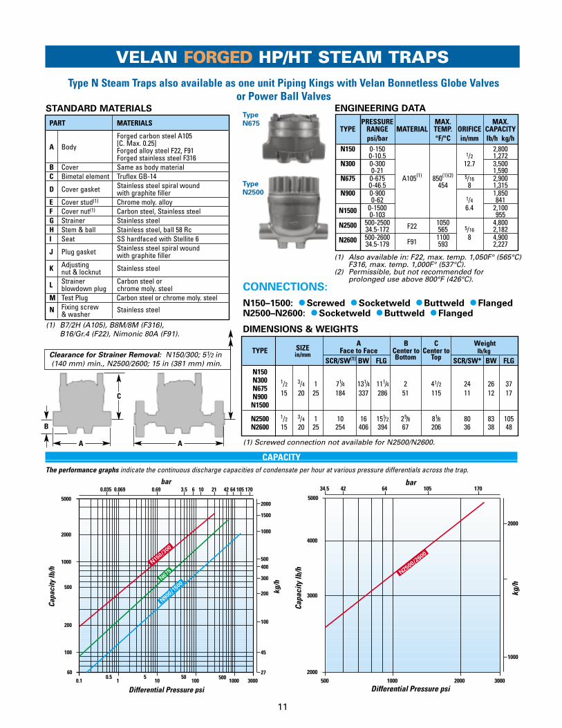
Type N Steam Traps also available as one unit Piping Kings with Velan Bonnetless Globe Valves or Power Ball Valves
PART MATERIALS
Forged carbon steel A105[C. Max. 0.25]A Body Forged alloy steel F22, F91Forged stainless steel F316
B Cover Same as body material C Bimetal element Truflex GB-14
D Cover gasket Stainless steel spiral wound with graphite filler
E Cover stud(1) Chrome moly. alloyF Cover nut(1) Carbon steel, Stainless steelG Strainer Stainless steelH Stem & ball Stainless steel, ball 58 RcI Seat SS hardfaced with Stellite 6
J Plug gasket Stainless steel spiral wound with graphite filler
K Adjusting Stainless steelnut & locknut
L Strainer Carbon steel orblowdown plug chrome moly. steel
M Test Plug Carbon steel or chrome moly. steel
N Fixing screw & washer
Stainless steel
STANDARD MATERIALS
(1) B7/2H (A105), B8M/8M (F316), B16/Gr.4 (F22), Nimonic 80A (F91).
(1) Also available in: F22, max. temp. 1,050F° (565°C)F316, max. temp. 1,000F° (537°C).
(2) Permissible, but not recommended for prolonged use above 800°F (426°C).
(1) Screwed connection not available for N2500/N2600.
SIZEA B C Weight
TYPE Face to Face Center to Center to lb/kgin/mmSCR/SW(1) BW FLG Bottom Top SCR/SW* BW FLG
N150N300 1/2 3/4 1 71/4 131/4 111/4 2 41/2 24 26 37N675N900 15 20 25 184 337 286 51 115 11 12 17
N1500
N2500 1/2 3/4 1 10 16 151/2 25/8 81/8 80 83 105N2600 15 20 25 254 406 394 67 206 36 38 48
DIMENSIONS & WEIGHTS
C
B
AA
PRESSURE MAX. MAX.TYPE RANGE MATERIAL TEMP. ORIFICE CAPACITY
psi/bar °F/°C in/mm lb/h kg/hN150 0-150 2,800
0-10.5 1/2 1,272N300 0-300 12.7 3,500
0-21 1,590N675 0-675 A105(1) 850(1)(2) 5/16 2,900
0-46.5 454 8 1,315N900 0-900 1,850
0-62 1/4 841N1500 0-1500 6.4 2,100
0-103 955N2500 500-2500 F22 1050 4,800
34.5-172 565 5/16 2,182N2600 500-2600
F911100 8 4,900
34.5-179 593 2,227
Type
N2500
Type
N675
500 1000 30002000
3000
2000
5000
4000
4234.5 10564 170
1000
2000
bar
Capa
city
lb/h
Differential Pressure psi
kg/h
N2500/2
600
CONNECTIONS:
N150–1500: ● Screwed ● Socketweld ● Buttweld ● FlangedN2500–N2600: ● Socketweld ● Buttweld ● Flanged
ENGINEERING DATA
CAPACITYThe performance graphs indicate the continuous discharge capacities of condensate per hour at various pressure differentials across the trap.
Clearance for Strainer Removal: N150/300; 51/2 in(140 mm) min., N2500/2600; 15 in (381 mm) min.

DESIGN FEATURES
● Hermetically sealed bodySeal welded body contains all operating parts.
● Positive closingThe bimetallic element is a function of thesaturated steam curve (pages 2 & 3) and it’ssensitivity to the temperature change assures animmediate reaction to both steam and condensatefor the entire pressure range. At saturatedtemperature the valve is closed.
● All-position installationSimplifies piping layout for easy plantstandardization.
● Self-aligning precision ball valveSingle free-floating stainless steel hardened Rc 58 min. ball valve.
● Valve seats StellitedAll Velan valve seats are Stellite faced to increase their resistance to the high degree of wear through velocity of flow, dirt and scale.
● Air venting - good discharge capacityAir and cold condensate is discharged through a full orifice efficiently ensuring fast warm-up of equipment.
VELAN HERMETICALLY SEALED STEAM TRAP
12
● Check valve operationThe main valve acts as a check valve preventing back flow.
● Positive condensate drainage for process work.
● Guaranteed against water hammerThe downstream valve acts as a release valve onthe excess water pressure without damage tointernal parts.
● Freezeproof installationVelan traps do not require a reservoir of primingwater in the body to operate. When installedvertically with inlet on top, they drain completelywhen cold, and are freezeproof without insulation.
APPLICATIONS
● Steam tracing, line drainage and most generalprocess applications.
F
E
D
IB
A
Type Q250 Stainless Steel Steam Traps for All Position Installation with Air Vent, Check Valve & Self-Aligning Precision Ball Valve
CGH
Type Q250

0.10.5
15
1050
100 600
100
60
200
500
1000
2000
5000
27
45
100
200
300
400500
1000
1500
2000
0.035 0.069 0.69 3.5 6 10 21 42
bar
Capa
city
lb/h
Differential Pressure psi
kg/h
Q25
0
13
SIMPLE PRINCIPLE OF OPERATION
A single free-floating ball valve:
● Vents air.
● Discharges condensate.
● Traps steam.
● Acts as a check valve.
(see page 2-4 for details)
VELAN HERMETICALLY SEALED STEAM TRAP
You need 19 types of hermetically sealed stainlesssteel inverted bucket steamtraps to cover the range of
this 1 Velan Steam Trapfor 0-250 psi (0-17 bar) and
2000 lb/h (907 kg/h) capacity.
A B C DTYPE SIZE Face to Overall Center to Center to Weight
in/mm Face Diameter Bottom Top lb/kg
1/2 4 31/2 7/8 25/8 2
Q25015 102 89 22 67 13/4 41/2 31/2 7/8 25/8 220 114 89 22 67 1
PART MATERIALSA Inlet shell Stainless steel 304L
B Outlet shell Same as inlet shell material
C Bimetal element Truflex GB-14
D Stem & ball SS, ball valve 58 Rc min.
E Seat Stellite 6
F Self locking adjustable nut
Stainless steel
G Fixing screw Stainless steel
H Inlet nipple Stainless steel 304L
I Outlet nipple Stainless steel 304L
STANDARD MATERIALS
DIMENSIONS & WEIGHTS
B
Type
Q250
PRESSURE MAX. MAX.TYPE RANGE MATERIAL TEMP. ORIFICE CAPACITY
psi/bar °F/°C in/mm lb/h kg/h
0-250 SS 304L 500 3/8 2,700Q250 0-17 260 9.5 1,227
A
CD
CONNECTIONS:
● Screwed
● Socketweld
ENGINEERING DATA
CAPACITYThe performance graph indicates the continuous discharge capacities of condensate perhour at various pressure differentials across the trap.

VELAN HIGH CAPACITY PISTON OPERATED STEAM TRAP
● Check valve operationThe main valve acts as a check valve preventing back flow.
● Temperature Controllercontrols and adjusts the discharge temperature of condensate which can be calibrated using aspecial thermometer (see page 29).
● Other options include: Piping King Units,thermometer.SP only: Strainer blowdown valve.SPF 0-3 only: can include a “Y” Type strainerin line to protect trap.
APPLICATIONS ● SP & SPF: Reboilers, Purifiers, Vacuum pans,
Heat Exchangers, Evaporators, Feed WaterHeaters, Digesters, Desuperheaters, SteamSeparators, Flash Tanks, Large Autoclaves, Steam catapult service on U.S. Navy aircraftcarriers and other large capacity applications.
Type SPF & SP for High Pressure Service Smallest High Capacity Trap Ever Developed
TYPE SPF & SP DESIGN FEATURES
● Piston Cage Unit The advanced piston cage unitdesign combines a liner, piston,main seat and main valve intoone factory-tested assembly toensure precise alignment andsimple maintenance. In the SPFType there is also a bimetalliccage unit.
● Valve seats StellitedThe main and pilot valve seats are Stellite faced to increase their resistance to the high degree of wearthrough velocity of flow, dirt and scale.
● Small and lightweight designfor piping convenience, no mounting brackets required.
● All in one construction unitAir vent, main valve, check valve, strainer andtemperature controller are a single unit, ensuringperfect alignment and ease of maintenance.
● Positive closingAs steam contacts the bimetal element, the pullcloses the pilot valve, reducing the pressure onthe piston. Line pressure below the main valvecloses the valve tightly on the seat (see pg. 5).
● Positive condensate drainage for process work.
J
I
AA
I
D
D
K
H
D
L
14
B F EFM
E C
C
FC
D
D
D
B
G
B
Type SP (Cast)Type SPF (Forged)
J
PISTON CAGE UNIT

15
SIZEA B C WEIGHT
TYPE Face to Face Center Center lb/kgin
SCR/SW BW FLANGED to to SCR/SW BW FLANGEDmm200 350 600 1500 Bottom Top 200 350 600 1500
SPF 1 11/2 73/4 133/4 103/4 11 11 123/4 47/8 53/16 35 39 48 53 56 640,1, 2,3 25 40 197 349 273 279 279 324 124 132 16 18 22 24 25 29
SPF 11/2 2 83/4 143/4 12 12 12 141/4 51/8 51/2 50 55 67 69 81 1004,5,6,7 40 50 222 375 305 305 305 362 130 140 23 25 30 31 37 45
PART MATERIALS
SPF SP
Forged carbon steel A105 Cast steelA Body Forged alloy steel F22 WCBB Cover Same as body material C Bimetal element Truflex GB-14D Gasket Stainless steel spiral wound
with graphite fillerE Cover stud(1) Chrome moly. alloy B7F Cover nut(1) Carbon or stainless steel Carbon steel 2HG Cap screw(2) Chrome moly. alloy –H Strainer – Stainless steelI Piston cage unit Stainless steelJ Pilot valve Stainless steel, ball 58 Rc min. K Blowdown plug – Carbon steelL Bottom plug – Stainless steelM Temp controller Stainless steel
VELAN HIGH CAPACITY PISTON OPERATED STEAM TRAP
DIMENSIONS & WEIGHTS
Type
SPF
Type
SP
(1) B7/2H (A105), B16/Gr.4 (F22), B8M/8M (F316).(2) F316 applies to SPF0-3 design only.
* Fraction represents orifice size.
PRESSURE MAX. TEMP. MAX.TYPE RANGE °F/°C
ORIFICECAPACITY
psi/bar A105/WCB F316 F22in/mm lb/h kg/h
SPF0 10-200 17,0000.69-14 7,727
SPF1 10-350 19,0000.69-24 850(1) 1000 1050 7/8 8,636
SPF2 10-600 454 537 565 22 22,0000.69-42 10,000
SPF3 10-1500 27,0000.69-103 12,273
SPF4 10-200 38,0000.69-14 17,272
SPF5 10-350 43,0000.69-24 850(1) N/A 1050 13/8 19,545
SPF6 10-600 454 N/A 565 35 49,0000.69-42 22,272
SPF7 10-1500 63,0000.69-103 28,636
SP6 10-200 90,0000.69-14 40,90910-600 850(1) N/A 2 130,000SP7 0.69-42 454 51 59,09010-1500 160,000SP8 0.69-103 72,727
A B C WEIGHTSIZE Face to Face Center Center lb/kg
TYPE inSCR/SW BW
FLANGED to to SCR/SW BW FLANGEDmm 200 600 1500 Bottom Top 200 600 &1500 200 600 &1500 200 600 &15002 118 123 139 170
SP 50 15 21 54 56 63 776,7,8 21/2 381 533 18 19 22 91/8 41/4 115 120 120 125 151 192
65 457 483 559 232 108 52 55 55 57 69 873 16 22 122 127 155 21680 406 559 56 58 70 98
10 100 1000500 3000507000
10,000
20,000
30,000
40,000
50,00060,00070,00080,00090,000
100,000
200,000
0.69 63.5 10 21 1056442 170
3200
4545
10,000
15,000
20,000
25,000
30,00035,00040,00045,00050,00060,00070,00080,000
bar
Capa
city
lb/h
Differential Pressure psi
kg/h
SPF-13 /8*
SPF-7 /8*
SP-2*
A
A
B
B
C
C
CONNECTIONS:
● Screwed ● Socketweld● Buttweld ● Flanged
STANDARD MATERIALS CAPACITYThe performance graph indicates the continuous discharge capacities ofcondensate per hour at various pressure differentials across the trap.
Clearance for Strainer
Removal:SP 12 in
(305 mm) min.
(1) Permissible, but not recommended for prolonged useabove 800°F (426°C).

16
VELAN PIPING KING PACKAGE UNITS
Velan Forged Piping King Automatic Condensate Drain Units
A Unique Method in Steam Trap Piping
Bypass
Steam Trap
Inclined Bonnetless Globe & Stop Check Valve
Velan Piping Kings Provide Substantial Savings,in Component Parts & Installation Costs
CONVENTIONAL UNIT WITH
BYPASS (3 VALVES) AND BUCKET TRAP
VELAN PIPING KING UNIT WITH
BYPASS (2 VALVES ONLY)
1 Unit - 5 Welds1 Velan Piping King 3/4” Type NV-BY5 Welded Joints (1 hour)
Fitting Time (10 minutes)
1 2
3 4 7 8
9
10
11
12
1314
15
1820
5
6
17
16
19
21
22
23
1
2
3
4
561 2
3
4
570 Minutes8 Hours
6 Units - 23 Welds1 Steel 3/4” Bucket Steam Trap 2 Elbows 3/4” (s.w.)3 Forged Steel Valves 3 Tees 3/4” (s.w.)1 Steel Strainer 3/4” 2 Unions 3/4”1 Steel Check Valve 3/4” Fitting Time (2 hours)23 Welded Joints (6 hours)
The Piping King Package unit fitted with a bypass, enables the steam trap to be isolated from the system allowing routine main-tenance to be carried out.
THE UNIT CONSISTS OF:
● The unique patented Universal Steam Trap with integral strainer and check valve
● Two high-quality bonnetless forged steel special stop check globe valvesmounted on either side of the trap.
The valves are connected bythe bypass pipe, enabling thesteam trap to be isolatedwhile the steam flow ismaintained.
Piping King units are usedextensively in power stationsmarine and similarapplications wherecontinuous operation isessential during routinemaintenance. (See page 18, 19 for details.)
Check Valve
Bucket trap
Strainer

17
HOW IT WORKS
3. BYPASS OPEN - FULL FLOWTRAP ISOLATED FOR SERVICEPREFERRED SERVICE POSITION
Both inlet valve and outlet valves in bottomposition to seal off the trap against flowand back-pressure.
Trap is isolated and ready for service.
4. THROTTLED BY-PASSING - TRAP ISOLATED FOR SERVICE
Inlet valve in bottom position, outlet valvein intermediate position. The trap issealed off by the inlet valve and flowthrough the bypass is restricted by theposition of the outlet valve. The floatingcheck valve of the outlet valve protectsthe trap from back pressure.
1. AUTOMATIC STEAM TRAPOPERATION
Inlet valve and outlet valve both in top,closed position to provide double protectionagainst leakage through the bypass.
2. COMPLETE SHUTOFF - NO FLOWTRAP ISOLATED FOR SERVICE
Inlet valve in bottom position, outlet valve intop position. The trap is now sealed off bythe inlet valve and the bypass is closed bythe outlet valve. The valve is protected fromback-pressure by the check valve portion ofthe outlet valve.
Position of valvesBypass open - Trap isolated
Inlet Outlet
Trap isolated - Bypass openPosition of valves
Inlet Outlet
Bypass throttledBypass open
Check valve closed by line pressure through bypass
Trap isolated bypass open
Valves on backseats,Bypass closed
Inlet Outlet
Check valve closed by back pressure if any
Position of valves
Inlet Outlet
Trap closed Bypass closed
18
VELAN PIPING KING PACKAGE UNITS
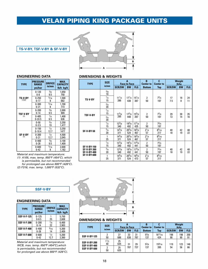
SIZE A B C WeightTYPE Face to Face Center to Center to lb/kg
in/mm SCR/SW BW FLG Bottom Top SCR/SW BW FLG
SSF-V-BY-1252 27 33 31 53/8 1611/16 198 198 20050 686 838 787 137 424 90 90 91
SSF-V-BY-200 11/2 25
SSF-V-BY-40040 635 31 29 53/8 159/16 119 123 146
SSF-V-BY-600 2 25 787 737 137 395 54 56 6650 635
DIMENSIONS & WEIGHTS
ENGINEERING DATA
PRESSUREORIFICE
MAX.TYPE RANGE CAPACITY
psi/bar in/mm lb/h kg/h0-120 3/8 1,6500-8 9.5 750
TS-V-BY 0-250 5/16 1,500(1)(2) 0-17 8 682
0-300 5/16 1,7000-21 8 7730-200 3/8 2,000
TSF-V-BY 0-14 9.5 909(1) 0-485 1/4 1,400
0-33.5 6.5 6360-50 3/4 3,2500-3.5 19 1,4770-150 1/2 3,2500-10.4 12.7 1477
SF-V-BY 0-300 1/2 4,500(1) 0-21 12.7 2,045
0-400 3/8 3,1000-28 9.5 1,4090-600 5/16 2,6000-42 8 1,182
SIZE A B C WeightTYPE Face to Face Center to Center to lb/kg
in/mm SCR/SW BW FLG Bottom Top SCR/SW BW FLG3/810
TS-V-BY1/2 111/4 171/4 151/4 2 73/4 17 18 2415 286 438 387 50 197 7.5 8 113/4201/2
TSF-V-BY15 115/8 175/8 155/8 2 73/4 29 30 353/4 295 448 397 50 197 13 14 16201/2 133/8 193/8 171/8 2 73/415 340 492 435 50 197
SF-V-BY-503/4 145/8 205/8 183/8 21/4 89/16 40 42 4820 371 524 467 57 217 18 19 221 145/8 205/8 183/8 21/4 89/1625 371 524 467 57 2171/2 133/8 193/8 173/8 2 73/4
SF-V-BY-150 15 340 492 441 50 197SF-V-BY-300 3/4 133/8 193/8 173/8 2 73/4 40 42 48SF-V-BY-400 20 340 492 441 50 197 18 19 22SF-V-BY-600 1 145/8 205/8 185/8 21/4 89/16
25 371 524 473 57 217
DIMENSIONS & WEIGHTS
B
C
TS-V-BY, TSF-V-BY & SF-V-BY
SSF-V-BY
A
B
C
A
ENGINEERING DATA
PRESSUREORIFICE
MAX.TYPE RANGE CAPACITY
psi/bar in/mm lb/h kg/hSSF-V-F-125 0-125 1 5,750
0-8.5 25 2,608SSF-V-F-200 0-200 7/8 6,400
0-14 22 2,903SSF-V-F-400 0-400 9/16 5,300
0-28 14 2,409SSF-V-F-600 0-600 1/2 5,200
0-42 12.7 2,360
Material and maximum temperature: WCB, max. temp. 850ºF (454ºC),whichis permissible, but not recommendedfor prolonged use above 800°F (426°C).
Material and maximum temperature: (1) A105, max. temp. 850°F (454°C), which
is permissible, but not recommendedfor prolonged use above 800°F (426°C).
(2) F316, max. temp. 1,000°F (532°C).

B
A
C
19
VELAN PIPING KING PACKAGE UNITS
SIZE A B C WeightTYPE Face to Face Center to Center to lb/kg
in/mm SCR/SW BW FLG Bottom Top SCR/SW BW FLG1/2 141/2 201/2 181/2 2 73/4 36 39 42
N-V-BY-67515 368 521 470 50 197 16 18 193/4 153/4 213/4 201/4 21/4 89/16 57 60 63
N-V-BY-900 20 400 552 514 57 217 26 27 29N-V-BY-1500
1 185/8 245/8 231/8 211/16 111/2 69 72 7525 473 625 587 68 292 31 33 341/2 181/2 241/2 24 27/8 91/8 96 100 110
N-V-BY-250015 470 622 610 73 232 43 45 50
N-V-BY-26003/4 213/8 273/8 267/8 3 121/4 120 125 14020 543 695 683 76 311 54 57 631 24 30 291/2 41/4 161/2 170 175 19025 610 762 749 108 419 77 79 86
DIMENSIONS & WEIGHTS
Material and maximum temperature: (1) A105/WCB, max. temp. 850°F (454°C) which
is permissible, but not recommended for prolonged use above 800°F (426°C).,
(2) F22, max. temp. 1,050°F (565°C),(3) F316, max. temp. 1,000°F (537°C),(4) F91, max. temp. 1,100°F (593°C).
Material and maximum temperature: (1) A105/WCB, max. temp. 850°F (454°C) which
is permissible, but not recommended forprolonged use above 800°F (426°C).,
(2) F22, max. temp. 1,050°F (565°C),(3) F316, max. temp. 1,000°F (537°C).
PRESSURE MAX.TYPE RANGE ORIFICE CAPACITY
psi/bar in/mm lb/h kg/h
N-V-BY-150 0-150 2,800(1)(2)(3) 0-10.5 1/2 1,272
N-V-BY-300 0-300 12.7 3,500(1)(2)(3) 0-21 1,590
N-V-BY-675 0-675 5/16 2,900(1)(2)(3) 0-46.5 8 1,315
N-V-BY-900 0-900 1,850(1)(2)(3) 0-62 1/4 8,41
N-V-BY-1500 0-1500 6.4 2,100(1)(2)(3) 0-103 955
N-V-BY-2500 500-2500 4,800(2) 34.5-172 5/16 2,182
N-V-BY-2600 500-2600 8 4,900(4) 34.5-179 2,227
ENGINEERING DATA
B
C
A
SIZE A B C WeightTYPE Face to Face Center to Center to lb/kg
in/mm SCR/SW BW FLG Bottom Top SCR/SW BW FLG
SPF0-V-BY 1 191/8 251/8 231/8(1) 211/16 111/2
SPF1-V-BY 25 486 638 587 68 292 90 93 118SPF2-V-BY 11/2 213/4 273/4 253/4(1) 53/8 159/16 41 42 63SPF3-V-BY(1) 40 552 705 654 137 395SPF4-V-BY 11/2 223/4 283/4 263/4(2) 53/8 159/16
SPF5-V-BY 40 578 730 679 137 395 167 170 217SPF6-V-BY 2 243/4 303/4 283/4(2) 53/8 1611/16 75 77 98SPF7-V-BY(2) 50 629 781 730 137 424
2 32 38 36(3)
SP6-V-BY50 813 965 914
21/2 38 38 38(3) 53/8 1611/16 275 275 286SP7-V-BY 65 965 965 965 137 424 125 125 130SP8-V-BY(3)
3 38 38 38(3)
80 965 965 965
DIMENSIONS & WEIGHTS
PRESSUREORIFICE
MAX.TYPE RANGE CAPACITY
psi/bar in/mm lb/h kg/hSPF0-V-BY 10-200 17,000
(1)(2)(3) 0.69-14 7,727SPF1-V-BY 10-350 19,000
(1)(2)(3) 0.69-24 7/8 8,636SPF2-V-BY 10-600 22 22,000
(1)(2)(3) 0.69-42 10,000SPF3-V-BY 10-1500 27,000
(1)(2)(3) 0.69-103 12,273SPF4-V-BY 10-200 38,000
(1)(3) 0.69-14 17,272SPF5-V-BY 10-350 43,000
(1)(3) 0.69-24 13/8 19,545SPF6-V-BY 10-600 35 49,000
(1)(3) 0.69-42 22,272SPF7-V-BY 10-1500 63,000
(1)(3) 0.69-103 28,636SP6-V-BY 10-200 90,000
(1) 0.69-14 40,909SP7-V-BY 10-600 2 130,000
(1) 0.69-42 51 59,090SP8-V-BY 10-1500 160,000
(1) 0.69-103 72,727
ENGINEERING DATA
(1) For SPF3-V-BY with Flanged Connection, A (face to face) for 1” is 23 5/8” (600 mm) and for 11/2” is 261/4” (669 mm).
(2) For SPF7-V-BY with Flanged Connection, A (face to face) for 11/2” is 271/4” (692 mm) and for 2” is 31 3/4” (806 mm).
(3) For SP8-V-BY with Flanged Connection, A (face to face) is 39” (991 mm) for all sizes.
SPF0-V-BY TO SPF7-V-BY
SP6-V-BY TO SP8-V-BY
N-V-BY-150, N-V-BY-300,
N-V-BY-675, N-V-BY-900,
N-V-BY-1500, N-V-BY-2500,
N-V-BY-2600ALSO AVAILABLE
WITH VELAN
POWER BALL VALVE:
• Two isolating valves
• Three bypass valves

TYPE MFT & MFTS DESIGN FEATURES
● Positive closing and condensate drainageThe bimetallic element is a function of thesaturated steam curve (pages 2 and 3) and it’ssensitivity to the temperature change assures animmediate reaction to both steam and condensatefor the entire pressure range. At saturated steamtemperature the valve is closed as on a standardbimetallic steam trap, however, in this type anycondensate build-up even at saturated steamtemperature is discharged at the same rate. As it reaches the trap, the float becomes buoyantand opens the valve mechanically (see page 5).
● Stainless Steel Float & Trim
● Simple InstallationMultiple inlet and outlet connections facilitateinstallation.
● Integral strainer Stainless steel screens are integral to protect thetrap operating mechanism from damage by dirt or scale. No extra fittings or installation costs arerequired. Free strainer area minimum 5 to 1.Perforation is 0.031” (0.8 mm).
● Integral check valve operationThe main valve acts as a check valve preventing back flow.
● Stainless steel pivotsAssure adequate protection against wear.
20
VELAN MONOVALVE FLOAT BIMETALLIC STEAM TRAPS
Type MFT1, 2, 3 & 4
Type MFT/MFTS For Positive Drainage of Unit Heaters & Process EquipmentA Complete Unit: Built-in Strainer, Check Valve,
Air Vent & Optional Bypass Shut-Off
Type MFT0
APPLICATIONS
Where positive drainage is essential andcondensate back-up cannot be tolerated. ● Unit Heaters, ● Laundry Presses, ● Calorifiers, ● Ironers, ● Calendars, ● Drying Cylinders and otherapplications where condensate has to bedischarged at steam temperature.
● Seat (J) stellite faced to increaseresistance to the high degree of wearthrough velocity of flow, dirt and scale.
● Guaranteed against water hammer.The down-stream valve acts as a releasevalve on the excess water pressurewithout damage to internal parts.
● Freezeproof installation without insulation – complete drainage when cold.
● Other options include: NPT blow down plug,strainer blowdown valve and Piping King Units.
(E) Float
(C) Bimetal element
(I) Ball valve
CAGE UNIT

PART MATERIALSMFT0-5 MFTS
A Body Cast iron Gr. 220(1) Cast steel WCBB Cover Same as body material C Bimetal element Truflex GB-14D Bimetal holder Stainless steelE Float Stainless steelF Cover gasket Stainless steel with non-asbestos filler G Cover screw(2) High tensile steel Gr. SH Strainer Stainless steelI Stem & ball Stainless steel, ball 58 RcJ Seat SS hardfaced with Stellite 6 K Self-lock
adjusting nut Stainless steel
L Pivot Plug Stainless steel
21
VELAN MONOVALVE FLOAT BIMETALLIC STEAM TRAPS
STANDARD MATERIALS
1 5 10 50 100 300
500
200
1000
5000
10,000
20,000
0.069 0.69 103.5 6 210.35
200
100
2000
1000
500400
300
3000
40005000
9000
bar
Capa
city
lb/h
Differential Pressure psi
kg/h
MFT4 15 psi
3/4*
MFT3 15 psi
5/8*
MFT2 15 p
si, M
FT4 50 psi
1/2*
MFT3 50 p
si 7/16*
MFT1 15 p
si, M
FT4 125 psi
3/8*
MFT2 50 p
si, M
FT3 125 psi,
MFT4 200 p
si 5/16*
MFT2 1
25 psi,
MFT3 200 p
si 1/4*
MFT1 50/1
25 psi, M
FT2 200 psi 7/32*
1 5 10 50 100 300
500
200
1000
5000
10,000
20,000
0.069 0.69 103.5 6 210.35
200
100
2000
1000
500400
300
3000
40005000
9000
bar
Capa
city
lb/h
Differential Pressure psi
kg/h
MFT5 15 psi
3/8*
MFT5 50/125 psi
7/32*MFTS 1
50 psi
5 /16*
MFTS 230/3
00 psi 7/32*
MFT0
7/32*
Type MFT5/MFTS
H A KF
B
I J L DC
TYPE MFT0, MFTS, MFT5
TYPE MFT1, 2, 3, 4
E
CONNECTIONS:
MFT0–5: ● Screwed
MFTS: ● Screwed ● Socketweld ● Buttweld ● Flanged
CAPACITYThe performance graphs indicate the continuous discharge capacities ofcondensate per hour at various pressure differentials across the trap.
* Fraction represents orifice size.
(1) MFT0: Material is Cast Iron Gr. 250.(2) MFTS: Material is B7.Note: Part “G” is not shown above for clarity.

22
DC
AB
VELAN MONOVALVE FLOAT BIMETALLIC STEAM TRAPS
DC
AB
B
A A C
Type MFT0
Type MFT1, 2, 3, & 4
Type MFTS, MFT5
SIZE A B C WeightTYPE Face to Face Center to
Lengthlb/kg
in/mm SCR/SW BW FLG Top SCR/SW BW FLG
MFT51/2 3/4 1 311/16
N/A N/A51/4 91/4 12
N/A N/A15 20 25 94 133 235 5.5
MFTS1/2 3/4 1 311/16 911/16 6 51/4 91/4 18 20 3015 20 25 94 246 152 133 235 8 9 14
DIMENSIONS & WEIGHTS
SIZE A(1) B(2) C(3) D WeightTYPE in/mm Face to Face Center to Center Center to Face Length lb/kg
MFT11/2 3/4 1 6 5/8 3 15/16 13/8 85/16 1215 20 25 168 100 35 211 5.5
3/4 1 711/16 43/4 17/16 9 3/8 15
MFT220 25 195 121 37 238 7
11/4 11/2 8 41/2 13/4 10 3/8 1732 40 203 114 44 264 8
11/2 9 51/2 13/4 12 3/4 33
MFT340 229 140 44 324 152 101/4 55/8 21/4 131/2 3550 260 143 57 343 16
MFT4 2 11 61/2 21/4 141/2 5150 279 165 57 368 23
DIMENSIONS & WEIGHTS
SIZE A B(1) C(2) D WeightTYPE in/mm Height Center to Face Center to Face Length lb/kg
MFT01/2 3/4 61/8 43/8 11/8 6 3/4 8.7515 20 156 111 29 171 4
DIMENSIONS & WEIGHTS
PRESSURE MAX.ORIFICE
MAX.TYPE RANGE MATERIAL TEMP. CAPACITY
psi/bar °F/°Cin/mm
lb/h kg/hMFT0 0-125 Cast Iron 428 7/32 1,650
0-8.5 Gr.250 220 5.5 7500-15 3/8 3,2500-1 9.5 1,477
MFT1 0-50 Cast 428 7/32 1,2500-3.5 Iron 220 5.5 5680-125 Gr.220 7/32 1,7000-8.5 5.5 7720-15 1/2 7,0000-1 12.7 3,1820-50 5/16 3,2000-3.5 Cast 8 1,455
MFT2 0-125 Iron 428 1/4 2,6000-8.5 Gr.220 220 6.4 1,1820-200 7/32 2,0000-14 5.5 9090-15 5/8 12,0000-1 16 5,455
MFT3 0-50 Cast 428 7/16 8,0000-3.5 Iron 220 11 3,6360-125 Gr.220 5/16 4,5000-8.5 8 2,0450-200 1/4 3,2000-14 6.4 1,4550-15 3/4 17,5000-1 19 7,9550-50 1/2 12,0000-3.5 Cast 12.7 5,455
MFT4 0-125 Iron 428 3/8 8,0000-8.5 Gr.220 220 9.5 3,6360-200 5/16 5,8000-14 8 2,6360-15 3/8 3,3000-1 9.5 1,477
MFT5 0-50 Cast 428 7/32 1,2500-3.5 Iron 220 5.5 5680-125 Gr.220 7/32 1,7000-8.5 5.5 7720-150 5/16 4,2000-10.5 Cast 8 1,909
MFTS 0-230 Carbon 650 7/32 1,9000-16 Steel 343 5.5 8630-300 WCB 7/32 2,1000-21 5.5 955
(1) Center of inlet to outlet face. (2) Center of outlet to inlet face.
(1) Vertical connection. (2) Horizontal connection. (3) Center of vertical outlet to face of horizontal outlet.
MFT1-4,
Screwed
connection
only.
MFT5: Screwed connection only.
MFTS: Screwed SocketweldButtweld & Flanged connections.
MFT0, Screwed
connection only.
ENGINEERING DATA

0.10.5
15
1050
100 600
100
60
200
500
1000
2000
3000
27
45
100
200
300
400
500
1000
0.035 0.069 0.69 3.5 6 10 21
1300
bar
Capa
city
lb/h
Differential Pressure psi
kg/h
ACF
SIZE A B C D WeightTYPE Face Center Center Center
in to to to to lbmm Face Plug Bottom Top kg
ACF 1/2 3 1/4 11/8 1 1/2 2 1.515 83 29 38 51 0.68
DESIGN FEATURES ● Positive closing. Every Velan trap closes tightly
at saturated steam temperature.
● Simple MaintenanceOperating parts are contained in one easilyaccessible unit for quick and easy maintenance.
● Stainless Steel Trim
● No bellows to be damaged by water hammer. An automatic release in Velan traps.
● Horizontal or vertical installation and dual outlet
● Freezeproof installationVelan traps drain completely when cold, and aretherefore freezeproof without insulation.
● Automatic air venting - good discharge capacityAir and cold condensate is discharged through a full orifice efficiently ensuring fast warm-up of equipment.
● Compact & efficient design. Operating parts arecontained in one unit – quick & easy access.
APPLICATIONS ● Natural draught convectors, ● Steam radiators, ● Hot tables & cupboards, ● Small coils, Tea kettles, ● Vacuum systems & Air venting.
23
VELAN SPACE HEATING STEAM TRAPS
C
A HIJ
B
E F G D
Type ACF Bimetallic Heating Trap For Radiators, Convectors, Low & High Pressure Heating Systems
PART MATERIALS
A Body Brass pressing (CZ122)B Cover Same as body material C Bimetal element Truflex GB-14D Cover gasket Wire reinforced graphite fillerE Cover bolts Chrome moly. alloyF Stem & ball Stainless steelG Self-lock
adjusting nutStainless steel
H Plug Carbon steelI Union nut BrassJ Male union Brass
STANDARD MATERIALS
DIMENSIONS & WEIGHTS
D
C
A B
PRESSURE MAX. MAX.RANGE MATERIAL TEMP. ORIFICE CAPACITYpsi/bar °F/°C in/mm lb/h kg/h
0-40 1,0000-3 Brass 388 3/8 455
0-120 Pressing 198 9.5 1,6000-8 CZ122 727
CAPACITYThe performance graph indicates the continuous discharge capacities ofcondensate per hour at various pressure differentials across the trap.
Dual Outlet
ENGINEERING DATA

24
VELAN THERMODYNAMIC STEAM TRAPS
● Freezeproof installationVelan traps do not require a reservoir of primingwater in the body to operate when installedvertically with inlet on top, they drain completelywhen cold, and are therefore freezeproof withoutinsulation.
● Positive condensate drainage for process work.
● Options for HPTD include: NPT blow down plug or blow-down valve and Piping King Unit.
APPLICATIONS
● HPTD, PTD & VTS
Multi-platen Presses, Garment Presses, Rubber and Plastic moulding equipment, Sterilizers and Laundry Ironers.
CONNECTIONS:
HPTD & VTS: ● Screwed ● Socketweld● Buttweld ● Flanged
PTD: ● Screwed
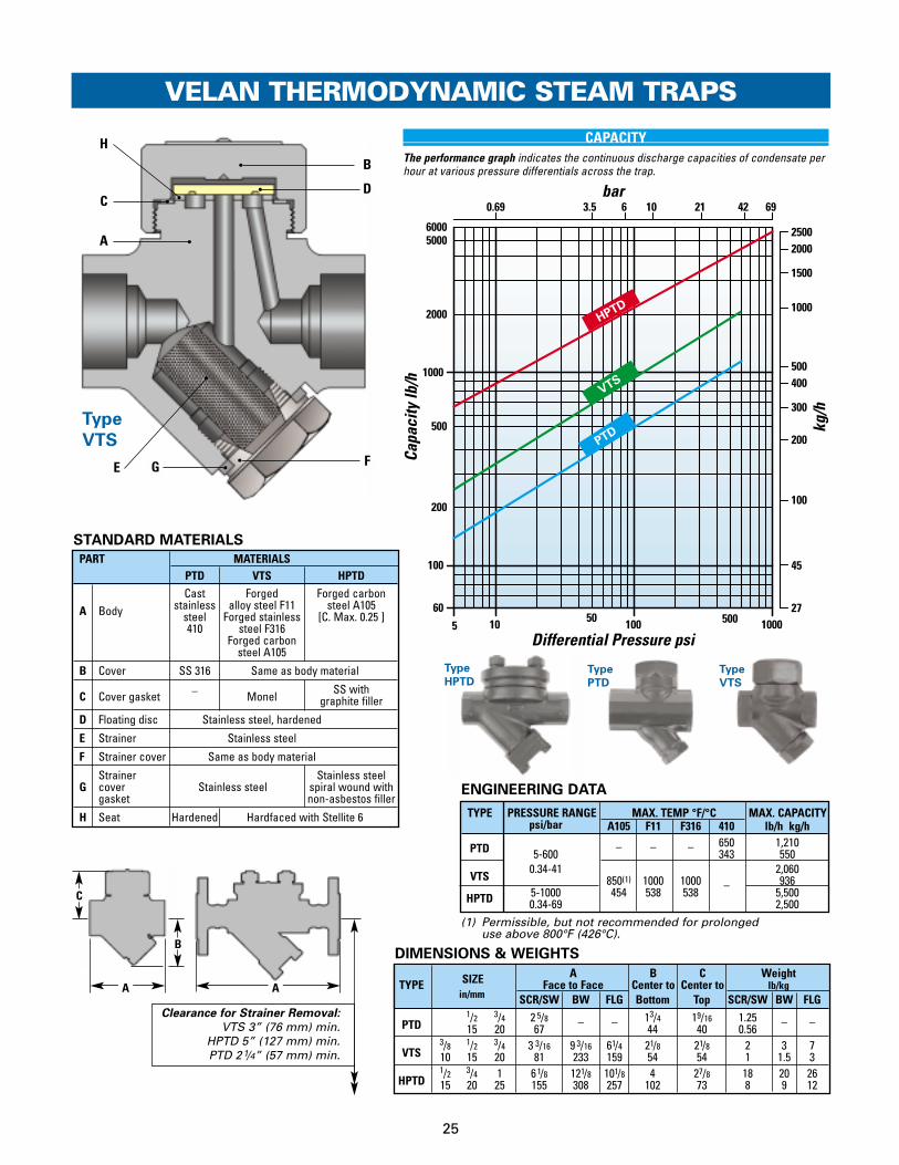
Type HPTD, PTD & VTS with Stainless Steel Hardened Floating Disc
TYPE VTS & HPTD DESIGN FEATURES
● Stainless steel hardened floating disc,ground and lapped with seat replaceable in line.
● Gaskets are spiral wound, stainless steel with graphite. Trim is stainless steel
● Valve seats StellitedMost Velan valve seats are Stellite faced toincrease their resistance to the high degree ofwear through velocity of flow, dirt and scale.
● Integral strainerStainless steel screens are integral in all threemodels to protect the trap operating mechanismfrom damage by dirt or scale. No extra fittings orinstallation costs are required. Free strainer areaminimum 5 to 1. Perforation is 0.031” (0.8 mm).
● Silent operation – no violent line shocks.
● Positive closingEvery Velan trap closes tightly on saturated steamtemperature. Positive closing for long periods ondry superheated steam lines has enormousadvantages in power plant and marine service.
● All-position installation simplifies piping layout.
Type
HPTD
Type
PTD
25
GE
D
B
F
C
H
A
Type
VTS
VELAN THERMODYNAMIC STEAM TRAPS
bar
Capa
city
lb/h
Differential Pressure psi
kg/h
VTS
PTD
HPTD
5 10 50 100 500 1000
500
100
60
200
1000
2000
200
100
45
27
2000
1500
1000
500400
300
0.69 103.5 6 21 42 69
60005000
2500
STANDARD MATERIALS
C
PART MATERIALSPTD VTS HPTDCast Forged Forged carbon
stainless alloy steel F11 steel A105A Body steel Forged stainless [C. Max. 0.25 ]410 steel F316
Forged carbon steel A105
B Cover SS 316 Same as body material
C Cover gasket – MonelSS with
graphite filler
D Floating disc Stainless steel, hardened
E Strainer Stainless steel
F Strainer cover Same as body material
Strainer Stainless steel G cover Stainless steel spiral wound with
gasket non-asbestos filler
H Seat Hardened Hardfaced with Stellite 6
A A
B
SIZE A B C WeightTYPE Face to Face Center to Center to lb/kg
in/mm SCR/SW BW FLG Bottom Top SCR/SW BW FLG
PTD1/2 3/4 2 5/8 _ _ 13/4 19/16 1.25 _ _15 20 67 44 40 0.56
VTS3/8 1/2 3/4 3 3/16 9 3/16 61/4 21/8 21/8 2 3 710 15 20 81 233 159 54 54 1 1.5 3
HPTD1/2 3/4 1 61/8 121/8 101/8 4 27/8 18 20 2615 20 25 155 308 257 102 73 8 9 12
DIMENSIONS & WEIGHTS
ENGINEERING DATA
TYPE PRESSURE RANGE MAX. TEMP °F/°C MAX. CAPACITYpsi/bar A105 F11 F316 410 lb/h kg/h
PTD – – – 650 1,2105-600 343 550
VTS0.34-41 2,060
850(1) 1000 1000 – 936HPTD 5-1000 454 538 538 5,500
0.34-69 2,500
CAPACITYThe performance graph indicates the continuous discharge capacities of condensate perhour at various pressure differentials across the trap.
Clearance for Strainer Removal:
VTS 3” (76 mm) min.HPTD 5” (127 mm) min.PTD 21/4” (57 mm) min.
(1) Permissible, but not recommended for prolonged use above 800°F (426°C).
Type
VTS
Type
PTD
Type
HPTD

H A KF
M
I J L DC
B E
26
COMPRESSED AIR DRAINAGE
In much the same way as steam, but for quitedifferent reasons, compressed air gives up moistureas it cools. The act of compression raises thetemperature of the air and even when passedthrough an after-cooler, it still has heat to loosebefore reaching the point at which it is used.
Water vapor carried in compressed air condensesand collects in the bottom of receivers, tanks orseparators, and in low points of compressed airlines. If such accumulations are not removed, thepassing air will pick up moisture, which may causerusting, sticking or spoiled work.
TYPE MFA & MFAS DESIGN FEATURES
The Velan Type MFA float trap automaticallyremoves accumulated water from compressed airsystems. Construction is similar to the Type MFTSteam Trap except that there is no thermostaticelement. A boss is provided on top of the cover,tapped for a 3/8” (10 mm) air circulating pipe whichis necessary unless the trap is fitted directly under and so close to the drain point that air entering the trap can escape back through the inlet.
● Stainless Steel Float & Trim
● Simple InstallationMultiple inlet and outlet connections facilitatehorizontal, vertical or angle installation.
VELAN COMPRESSED AIR DRAIN TRAPS
Type MFA1 & 2
Type MFA/MFAS For Pneumatic Use – Power Tools Blowing Moulds & PaintA Complete Unit: Built-In Strainer, Check Valve & Air Vent with
Dual Inlet & Outlet Connections
Type
MFA0
● Integral strainer Stainless steel screens are integral to protect thetrap operating mechanism from damage by dirt or scale. No extra fittings or installation costs arerequired. Free strainer area minimum 5 to 1.Perforation is 0.031” (0.8 mm).
● Integral check valve operationThe main valve acts as a check valve preventing back flow.
● Stainless steel pivotsAssure adequate protection against wear.
● Seat Stellite facedto increase resistance to the high degree of wearthrough velocity of flow, dirt and scale.
● Freezeproof installation Freezeproof without insulation – complete drainage when cold.
APPLICATIONS
Pneumatic power tool operation:● Air operated chucks, ● Air operated cutters
Pneumatic blowing operation: ● Foundry mould blowing, ● Paint shop spraying
Type MFAS

PRESSURE MAX. MAX.TYPE RANGE MATERIAL TEMP. ORIFICE CAPACITY
psi/bar °F/°C in/mm lb/h kg/h
MFA0 Cast Iron 4,5000-125 Gr.250 2,045
MFA1 0-8.5 428 4,500Cast Iron 220 2,045
MFA2 0-200 Gr.220 6,0000-14 7/32 2,7270-150 5.5 3,0000-10.5 Cast 1,364
MFAS 0-230 Carbon 650 3,5000-16 Steel 343 1,5900-300 WCB 4,0000-21 1,818
27
PART MATERIALSMFA-0,1,2 MFA-S
A Body Cast iron Gr. 220(1) Cast steel WCBB Cover Same as body material C Plate Stainless steel 1/8” thickD Holder Stainless steelE Float Stainless steelF Cover gasket Stainless steel with non-asbestos filler G Cover screw High tensile steel Gr. SH Strainer Stainless steelI Stem & ball Stainless steelJ Seat(2) SS hardfaced with Stellite 6 K Self-lock adjusting nut Stainless steelL Pivot Plug Stainless steel
MConnection
3/8” NPTfor balance pipe
VELAN COMPRESSED AIR DRAIN TRAPS
STANDARD MATERIALS
1 5 10 50 100 600
200
500
1000
5000
100
200
300
400
500
1000
1500
2000
0.069 0.69 3.5 6 10 21 42
10,000
3000
4000
bar
Capa
city
lb/h
Differential Pressure psi
kg/h
MFA
S
MFA
0, 1 &
2
(1) Cast Iron Gr. 250 for MFA0 (2) MFA0: hardened seat.
TYPE MFA0, 1, 2 & MFAS
ENGINEERING DATA
MFA0, 1, 2: Screwed connection only.
MFAS: Screwed, Socketweld, Buttweld & Flanged connections.
CAPACITYThe performance graph indicates the continuous discharge capacities ofcondensate per hour at various pressure differentials across the trap.
SIZE A B C WeightTYPE Face to Face Center to Overall lb/kg
in/mm SCR/SW BW FLG Top Length SCR/SW BW FLG
MFAS1/2 3/4 1 311/16 911/16 6 51/4 91/4 18 20 3015 20 25 94 246 152 133 235 8 9 14
DIMENSIONS & WEIGHTS
(1) Center of inlet to outlet face. (2) Center of outlet to inlet face.
SIZE A(1) B(2) C(3) D WeightTYPE in/mm Face to Face Center to Center Center to Face Length lb/kg
MFA11/2 3/4 1 6 5/8 3 15/16 13/8 85/16 1215 20 25 168 100 35 211 5.5
MFA2 3/4 1 711/16 43/4 17/16 9 3/8 1520 25 195 121 37 238 7
MFA2 11/4 11/2 8 41/2 13/4 10 3/8 1732 40 203 114 44 264 8
SIZE A B(1) C(2) D WeightTYPE in/mm Height Center to Face Center to Face Length lb/kg
MFA01/2 3/4 61/8 43/8 11/8 63/4 8.7515 20 156 111 29 171 4
(1) Vertical connection. (2) Horizontal connection. (3) Center of vertical outlet to face of horizontal outlet.
DC
AB
DC
AB
B
A A
C
Type MFAS
Type MFA1, 2Type MFA0

28
INCLINED STRAINERSDESIGN FEATURES ● Forged body (A)
offers the advantages of high strength, structural integrity and reliability that make it an ideal choice for steam service.
● Stainless steel screen (B)can withstand severe abrasive service and iscarefully fitted to prevent leakage betweenthe screen and body.
Screens are normally supplied in stainlesssteel with 0.031” (0.8 mm) holes (26% freearea) and are also available in F22.
● Easy internal maintenanceStrainers are extremely easy to clean. They may be blown down by simply removingthe optional blow down plug or via a suitablevalve fitted in its place.
APPLICATIONS
Velan strainers protect steam traps,pumps, temperature and pressureregulators, gauges, instruments, airmotors and other equipment fromdirt, scale and other debris.
A
B
Gaskettedend
construction
Buttweld ends
SIZE A B CFace to Face Butt Weld (stubs) Center to
in SCR/SW BW(1) & FLANGED Bottommm
1500 2500 1500 2500 1500 2500 1500 25001/2 35/8 41/4 35/8 41/4 81/2 10 3/8 5 515 92 108 92 108 216 264 127 1273/4 41/4 41/4 41/4 41/4 9 10 3/4 5 3/8 53/420 108 108 108 108 229 273 136 1461 511/16 55/16 511/16 55/16 10 121/8 7
25 144 135 144 135 254 308 17811/4 7 61/4 7 11 133/4 81/232 178 159 178 297 349 216
11/2 7 63/4 7 12 151/8 81/232 178 171 178 305 384 2162 8 8 8 141/2 17 3/4 121/250 203 203 203 368 451 318
DIMENSIONS & WEIGHTS
(1) These buttweld dimensions do not comply with ASME/ANSI B16.10 (BS 2080). Velan reserves the right to vary specification from time to time.
C
A
B
Socketweld ends
Screwedends
Buttweld endswith stub
OPTIONAL BLOWDOWNPLUG
Alternative seal weld

29
ACCESSORIES
THERMOMETERThe Velan Thermometer is actuated by a bimetallic helix shaped strip, which is enclosed in stainless steel. Its strong design will with-stand adverse conditions and combines reliability with accuracy. The thermometer can be recalibrated on the spot and can be supplied with the following scales and ranges of operation:
32°F – 572°F (0°C – 300°C)Case diameter: 13/4” (45 mm)Length: 11/2” (38 mm)Screwed Connection: 1/4” NPT
32°F – 932°F (0°C – 500°C)Case diameter: 23/4” (70 mm) Length: 33/4” (95 mm)Screwed Connection: 1/4” NPT
TEMPERATURE CONTROLLERAVAILABLE FOR SSF, SPF, SF & SP
Velan Steam Traps are factory set to dischargecondensate below saturated steam temperature, to saveenergy up to 30% and no further adjustment is requiredprovided the trap is properly selected based on capacity.To change the discharge temperature you must turn theregulating nut of the temperature controller towards thebottom of the trap to increase the differential temperatureor away from the bottom of the trap to decrease thedifferential temperature. The movement of the regulatingnut is transferred directly without friction to the trap valveand the free movement of the valve is increased ordecreased accordingly. The result of the setting can bedetermined by checking the condensate’s temperaturewith a Velan thermometer installed on the trap. Otheruses for the temperature controller are:
a) Excessive back pressure can becompensated for by turning thecontroller away from the trapbottom.
b) If condensate is backed up, afaster rate of discharge isobtained by turning thecontroller away from the trapbottom, increasing the valveclearance.
c) If the trap leaks steam, and theseating faces are not dirty ordamaged, turning the controllertowards the trap bottom willreduce the valve clearance thusslowing the trap response time,preventing steam loss.
Blowdownvalve
VACUUM BREAKERS
Vacuum breakers should beinstalled wherever vacuumis created in pipelines orother equipment to ensuretrouble free operation suchas in heating coils foruninterrupted productionand elimination of freezing.
The units are factory set to operate at 5 inHg(mercury) (0.17 bar) vacuum but can easily be reset to suit plantconditions.
Other applications include: unit heaters,cooking kettles, blast coilsand air-conditioningequipment.
STANDARD MATERIALS
PART MATERIALS SPECIFICATION
1 Body Stainless steel BS 970-410S212 Stem and
Stainless steelStem: BS 970-410S21
ball Ball: AISI 440C3 Compression spring Stainless steel BS 970-303S214 Adjusting nut Stainless steel BS 970-410S215 Self locking nut Stainless steel BS 970-304S15
1
2
3
4
5
STRAINERBLOWDOWNVALVE
A rugged stainlesssteel blowdown valvecan be installed belowthe strainer in VelanSteam Traps as anoptional extra. Bodyand valve are bothstainless steelhardened. A forgedsteel globe, stop orneedle valve can befitted for highpressure operation orwhere greaterintegrity is required.
Connections:Inlet: 3/8” (10 mm) male screwed BSP or NPTOutlet: 1/8” (3 mm) female screwed BSP or NPT
SIZEOrifice A B WEIGHTNPT Thread
in/mm in/mm in/mm in/mm oz/g
1/2 1/2 11/2 2 3/8 415 13 38 60 1123/4 5/8 111/16 2 3/4 820 16 43 70 2241 3/4 2 3/16 2 3/4 1125 19 56 70 308
ENGINEERING DATA
B
A
Seating face hardfaced with
Stellite 6 and lapped with ball.

250 psi(17.2 bar)
406°F(208°C)
180°F
82°C
30
Typical Example:Oil Storage Tank Heating Coil
Required Heat Input: 2,000,000 Btu/h (504,000 kcal/h)
Steam Supply:250 psi/406°F (17.2 bar/208°C)
ENERGY (STEAM) INPUT Using Velan Bimetallic Traps
When using Velan Bimetallic Steam Traps the dischargetemperature of condensate is adjusted by a temperaturecontroller and most of the sensible heat in the conden-sate is saved. Condensate is discharged at 180°F (82°C). 231.5 (129)* [381.5-150 (212-83)*] are available to re-evaporate part of lodged conden-sate 820 (456)* required per lb (kg). 231.5 (129)* will evaporate 29% into live steam. Heat is trans-ferred to the oil efficiently and the heating process with high pressure condensate approaches heating with live steam.
STEAM DEMAND
2,000,000 Btu/h 1,900 lb/h= –––––––––––––––––– = (820 + 231.5) Btu/lb of Steam
or504,000 kcal/h 861 kg/h= –––––––––––––––––– =
(456 + 129) kcal/kg of Steam
Input per lb (kg)*1201 (668)* 100%
1051 (584)* 89% used
ENERGY (STEAM) INPUT Using Conventional Bucket, Float,Thermodynamic and Bellows Traps
Condensate is discharged as soonas it forms. The latent heat isextracted which, in our example, is 820 (456)* per pound of con-densate. Most of the sensible heat contained in the condensate381.5 (212)* or 32% is wasted.
STEAM DEMAND
2,000,000 Btu/h 2,440 lb/h= –––––––––––––––– = 820 Btu/lb of Steam
or504,000 kcal/h 1,105 kg/h= –––––––––––––––– =
456 kcal/kg of Steam
Input per lb (kg)*1201 (668)* 100%
820 (456)* 67% used
SAVINGS
STEAM SAVINGS 540 lb/h (244kg/h) [2,440-1,900 or 22% (1,105-861 or 22%)] 4,730,400 lb/year9,460 US $ /year (at 2 US $ for 1000 lb (455 kg) of SteamSubmit your steam trapping systems to Velan for free energy savings analysis
VELAN STEAM TRAPS
SAVE UP TO30% ENERGY
*Thermal Units are in Btu/lb (kcal/kg)
820 (456)*
820 (456)*
381 (212)*
381 (212)*
150 (83)*Temperature
Controller

COMPARISON OF PRINCIPLES OF OPERATIONWhat design features to look for when selecting a steam trap
FACTS FOR Velan Universal Thermostatic Float Bucket Thermodynamic
ESTIMATINGTRAP VALUE
Discharge valve Heat of steam closes Only by heat. Buoyancy and Closed by steam Closed by flow of hot con-actuated by: valve. Pressure weight of float. pressure. Opened by densate flashing into vapor.
opens valve when bucket weight and Opened by flow of cold condensate cools down. high levelage. condensate, no flashing.
Perfect discharge Condensate Selected trap size exactly Selected trap size exactly Selected trap size exactly Condensate when: cools down conforms with working conforms with working conforms with working temperature low.
pressure and capacity. pressure and capacity. pressure and capacity.Trap selection: Universal sizes According to capacity Certain after trial only Certain after trial only According to capacity
with large range and temperature. due to small adaptability due to small adaptability and temperature.to pressure and to pressure and capacity variations. capacity variations.
Incorrect selection Universal sizes Low discharge Steam loss. Steam loss Low discharge effects: capacity. No flow or No flow or capacity.
continuous flow. continuous flow.Adjusting facilities for The only trap adjustable None. None. New size or type None. New size or type None. changed conditions: for specific conditions. New size required required. New valve required. New valve New size or
No change of parts required orifice eventually. orifice eventually. type required.Ability for air Automatically with Automatic air None. Additional cost Small. Extra cost Automatically. elimination: full trap capacity. elimination. for air-bypass valve for auxiliary No additional
No additional valve No additional of valve and its installation air-bypass valve check valveAbility to handle cold Automatic cold water Automatic cold Intermittent discharge Automatic cold Automatic cold initial peakloads: discharge with full capacity condensate discharge causes shocks condensate discharge condensate dischargeAbility to handle ordinary Integral strainer in all None. Extra cost for None. Extra cost for None. Extra cost for None. sediment and sludge, units. Low first cost and strainer, additional fittings strainer additional fittings strainer. Clogging of bucket Extra cost for strainer dirt conditions: cheapest installation and installation and installation hole results in steam waste. and its installationAbsence of strainer Integral strainer Smaller flow. Smaller flow. No flow. No flow. Continuous flow. often causes: in all units Steam loss. Steam loss. Buckets vent plugged Steam waste.
Dirt getting into work- Dirt getting into work- or trap filled with dirt. Dirt, scale clogging ing parts and orifice. ing parts and orifice. Steam waste. seats and valve orifice.
Ability to handle Good as bimetal Good as bellow Small. Pressure high: Small. Pressure high: Good. pressure variations: follows saturated function of no flow. New valve orifice no flow. New valve orifice Depending on conden-
steam curve saturated steam for raised pressure for raised pressure sate temperatureAbility to handle Good due to Depending on Small. Small. Depending on variations in load: oversized orifice size of trap Continuous discharge Continuous discharge size of trap
of trap too small. of trap too small.Ability to close valve Yes. If required for 100% Small None None Smallon hot water only to steam loss proof operation. prevent steam loss: Adjustability by temper-
ature controller (optional)Ability to handle Patented discharge valve None. Extra cost for None. Extra cost for None. Extra cost for None. Extra cost for back pressure: operates as check valve. check valve, additional check valve. Steam loss check valve. Steam loss check valve. Steam loss if
No extra cost for separate fittings and their if sudden or frequent if sudden or frequent sudden or frequent check valve involved installation frequent drop in pressure. frequent drop in pressure. drop in pressure.
Installation The only all-position Only one position. Only horizontal. Not Only vertical. Costly Only horizontal. position: straight way type Additional cost for fitting. suitable for marine service piping. Not suitable for Costly piping
(float). Costly piping marine service (float)Installation Lowest. Installed directly High additional High. High. Fair. Extra cost for cost: in pipe line without cost for strainer, Extra cost for additional Extra cost for additional
fittings. Integral strainer, check valve. fittings, strainer, fittings, strainer,check valve, air-bypass. check valve, air vent. check valve, air vent.
Maintenance Lowest. High. High. Fair. Fair. Cost: One size interchangeable. Many sizes, large Many sizes, large Many sizes. Many sizes.
all over the plant. No fittings. stock of spare parts, stock of spare parts, Large stock of Large stock ofConsiderably reduced spare fittings. Short life of fittings. Short life of spare parts, fittings. spare parts, fittings.parts stock. Element cheap. flexible element. valve due to shocks. Delicate valve
Size, weight: Small, light weight Fair Large, heavy. Medium. For high capacity FairWeight up to 80 lb (36 kg) weight up to 80 lb (36 kg)
Freezeproof 100% freezeproof in vertical Special types. Not when None None Yesoperation: position. Valve widely open. trap fails and closes valve.Ability to control Automatic temperature None Precautions Precautions Nonetemperature in control for specific necessary. necessary.heat process: requirements; optionalSuperheated Highly recommended Good only up to Fair. Danger of Fair. Danger of Fair but always small steam: up to 1100°F (593°C). 500°F (260°C). re-evaporation body- re-evaporation of body- steam escapes.
Valve tightly closed or Expensive stainless water and tremendous water and tremendous high temperature. steel bellows. loss of steam. loss of steam.
NOTE: The information on this page is general in nature and not intended to show the exact design or performance of any specific manufacturer. The technical comparisons are not intended to downgrade other trap types but to compare their features and operating principles with the Velan Steam Trap.
31

SELECTION – SIZING
32
To determine the discharge capacity of steam traps,the following factors must be taken intoconsideration:
● Pressure differential between inlet and outlet
● Diameter of orifice
● Discharge temperature of condensate
The condensate capacity charts given for each typeare based on tests under working conditions andrepresent the actual maximum performance withcondensate at 40°F (22°C) below saturated steamtemperature, which is the standard setting.
Traps will normally commence opening at 15°F (8°C)below saturated steam temperature, but this can bevaried if required.
If the condensate is cooler, when starting up fromcold for instance, the capacities will be increasedconsiderably. A small increase in the setting of thetrap will result in a closer temperature differentialand an increase in capacity.
A decrease in setting will provide an element oftemperature control, discharging cooler condensateat predetermined temperatures, with reduced flowrates.
DETERMINING THE CAPACITY OF STEAM TRAPS
Calculate or estimate the maximum amount of steam condensate in lb/h or kg/h and multiply by theappropriate safety factor shown in the Table of Safety Factors (see bottom page 33).
Ascertain the minimum pressure at the trapping point and the maximum pressure liable to occur at theoutlet side of the trap. The difference of these two gives the Pressure Differential.
There are four possible arrangements for the trap, with corresponding variations in the Pressure Differential(Example: with steam at 20 psi (1.38 bar)):
Imperial Metric(A) Trap discharging to atmosphere:
Pressure on outlet of trap 0 0The Pressure Differential = 20 psi 1.38 bar
(B) Trap discharging into a closed return main with a positive backpressure of 5 psi 0.34 barPressure at trap outlet 20 - 5 psi 1.38 - 0.34 barThe Pressure Differential = 15 psi 1.04 bar
(C) Trap discharging into overhead return main, open to atmosphere, 6ft (1.8m) above the trap. The condensate therefore has to be lifted and causes a back pressure of approximately 1 psi for every 2 ft of lift (0.11 bar per meter).
20 - 6/2 1.39 - 0.11 x1.820 - 3 1.38 - 0.198
The Pressure Differential = 17 psi 1.18 bar
(D) Trap discharge into a vacuum, such as a condenser. In this case, as the trap pressure is above atmospheric pressure the condenser pressure must beadded to obtain the Pressure Differential. Condenser pressures normally are given by vacuum gauges in inches of mercury (inHg) and/or bar. When calculating in imperial units the inHg should be converted to psi as follows: 2 inHg corresponds to approximately 1 psi. If the vacuum gauge reads 16 inHg (-0.54 bar):
20 + 16/2 1.38 + 0.5420 + 8 +1.92 bar
The Pressure Differential = 28 psi
Having calculated the Pressure Differential refer to the individual Performance Charts and select a trap suitable for the estimated discharge at the Pressure Differential.
HOW TO SELECT THE SIZE AND TYPE OF TRAP FOR A GIVEN DUTY

33
MODEL
ACFO - ACF MFA5 - MFA5 TSOO - TSHPTD - HPTD MFTS - MFTS TSFO - TSFMFTO - MFTO MFAS - MFAS VBOO - Vacuum BreakerMFT1 - MFT1 NOOO - N VTSO - VTSMFT2 - MFT2 PTDO - PTDMFT3 - MFT3 QOOO - QMFT4 - MFT4 SFOO - SFMFT5 - MFT5 SSFO - SSFMFAO - MFAO SPFA - SPF 0, 1, 2 & 3MFA1 - MFA1 SPFB - SPF 4, 5, 6 & 7MFA2 - MFA2 SPOO - SP 6, 7 & 8
END CONNECTION TYPE
BUTTWELD: FLANGED: FLANGED:AO - SCH.40 (Raised Face) FJ - BST “A”BO - SCH.80 FA - ASME 150 FK - BST “D”CO - SCH.160 FB - ASME 300 FL - BST “E”DO - Combination Ends FC - ASME 600 FM - BST “F”WO - Socket Weld FD - ASME 1500 FN - BST “H”XO - Special Ends FE - ASME 2500 FO - BST “J”
FF - PN 10/16 FP - BST “K”SCREWED: FG - PN 25/40 FQ - BST “R”NO - NPT FH - PN 64 FR - BST “S”SO - BSP.P FI - PN 100 FS - BST “T”TO - BSP.T FX - Special
END CONNECTION SIZE
0 - Special 3 - 1⁄2” (15 mm) 6 - 11⁄4” (32 mm) 9 - 21⁄2” (65 mm)1 - 1⁄4” (8 mm) 4 - 3⁄4” (20 mm) 7 - 11⁄2” (40 mm) 10 - 3” (80 mm)2 - 3⁄8” (10 mm) 5 - 1” (25 mm) 8 - 2” (50 mm)
C
A
B
WORKING PRESSURE psig (maximum)
A - 15 G - 200 N - 2500 U - 230B - 25 H - 300 P - 40 V - 485C - 50 J - 350 Q - 120 W - 1000D - 100 K - 400 R - 250 X - SpecialE - 125 L - 600 S - 900 Y - 30F - 150 M- 1500 T - 675 Z - 2600
TYPE
A - Steam Traps F - Vacuum BreakerB - Trap with Integral Bypass G- Freeze ProtectorC - Piping King (No Bypass) H - Piping King (Isolating Valve)D - Piping King (with Bypass) X - SpecialE - Air Trap
BODY MATERIAL
1 - Special 6 - Chr. Moly., Alloy Steel, F22/WC92 - Carbon Steel, A105/WCB 7- Cast Iron4 - Chr. Moly., Alloy Steel, F91/C12A 8 - Bronze5 - Chr. Moly., Alloy Steel, F11/WC6 9 - Stainless Steel
ACCESSORIES
0 - None 5 - Combination1 - Temperature Controller 6 - Special2 - Strainer Blowdown Valve 7 - Sight Glass3 - Test Valve 8 - Thermometer4 - Strainer Plug 9 - Separate Strainer
TRIM OPTIONS
A - Special Element D - CombinationB - Welded Seat R - TruflexC - Screwed Seat O - None
D
S P F A W O 7 J A 2 1 R
Above example: SPFA (0, 1, 2 & 3), 11/2”socket weld connection, maximum 350 psig, in carbon steel, with temperature controller, and Truflex trim.
The figure numbers shown on this key are designed to cover essential features of Velan Steam Traps. Please use figure numbers to ensure prompt and accurate processing of your order. A detailed description must accompany any special orders.
G
Accessories
F
BodyMaterial
E
Type
D
WorkingPressure
psig (max)
B
EndConnection
Type
EndConnection
Size
A
Model
C H
TrimOptions
HOW TO ORDER
TABLE OF SAFETY FACTORS
Note: For a more detailed list of available trims, contact the factory or visit our web site at www.velan.com
E
F
G
H
TYPE OF EQUIPMENT SAFETY FACTORCoils (Blast, Unit Heaters), Air Heaters, Dryers, AirConditioning Plant:(a) Using inside air . . . . . . . . . . . . . . . . . . . . . . . . . . . . . . . . . . . 2(b) Using outside air: . . . . . . . . . . . . . . . . . . . . . . . . . . . . . . . . . . 3Kilns, Drying Room Ovens, Steam Mains, Paper Machines, Drying Cylinders, Autoclaves, Platens,Laundry Ironers, Sterilisers . . . . . . . . . . . . . . . . . . . . . . . . . . . . 3 Heat Exchangers Calorifiers, Jacketted pans, Hot water Heaters, Temperature Control and where throttling steam controls are used . . . . . . . . . . . 3-4
Example: A trap is required for a heat exchanger which issupplied with steam at 100 psi (7 bar) and has a consumption
of 1500 lb (680 kg) steam per hour. The trap discharges toclosed return main at a pressure of 10 psi (0.7 bar). The safety factor for this type application is 2.
Imperial MetricTrap Inlet Pressure 100 psi 7 barTrap Outlet Pressure 10 psi 0.7 barDifferential Pressure 90 psi 6.2 barSteam Consumption 1,500 lb/h 680 kg/hApplying Safety factor of 2 3,000 lb/h 1,365 kg/h
Therefore select trap from the individual Performance chartscapable of discharging 3,000 lb/h (1,365 kg/h) at a Differential Pressure of 90 psi (6.3 bar).
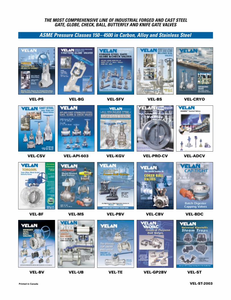
Printed in Canada VEL-ST-2003
ASME Pressure Classes 150– 4500 in Carbon, Alloy and Stainless Steel
THE MOST COMPREHENSIVE LINE OF INDUSTRIAL FORGED AND CAST STEEL GATE, GLOBE, CHECK, BALL, BUTTERFLY AND KNIFE GATE VALVES
VEL-PS VEL-BG VEL-SFV VEL-BS VEL-CRYO
VEL-BF VEL-MS VEL-PBV VEL-CBV VEL-BDC
VEL-CSV VEL-API-603 VEL-KGV VEL-PRO-CV VEL-ADCV
VEL-BV VEL-UB VEL-TE VEL-GP2BV VEL-ST