Embed Size (px)
Citation preview

www.white-rodgers.com
This thermostat is intended for use with a low voltage NEC Class II system. Do not use this thermostat with a line voltage system. If in doubt about whether your wiring is millivolt, line, or low voltage, have it inspected by a qualifi ed heating and air conditioning contractor or electrician.
Do not exceed the specifi cation ratings.
All wiring must conform to local and national electrical codes and ordinances.
This control is a precision instrument, and should be handled carefully. Rough handling or distorting components could cause the control to malfunction.
Blue 2” Single Stage ThermostatInstallation and Operating Instructions
Save these instructions for future use!
FAILURE TO READ AND FOLLOW ALL INSTRUCTIONS CAREFULLY BEFORE INSTALLING OR OPERATING THIS CONTROL COULD CAUSE PERSONAL INJURY AND/OR PROPERTY DAMAGE.
APPLICATIONS
For use with the following Class II systems:• Single Stage systems• Single-stage heat pump systems with no Aux heat
DO NOT USE WITH:• Systems exceeding 30 VAC and 1.5 amps• 3-wire zoned hydronic heating systems
1F80-0261 Thermostat
Model Programming Choices
1F80-0261 5/1/1 Day Programmable
SPECIFICATIONS Electrical Rating: Battery Power ................................................. mV to 30 VAC, 50/60 Hz or DC Input-Hardwire ................................................ 20 to 30 VACTerminal Load ........................................................ 1.0 A per terminal, 1.5A maximum all terminals combinedSetpoint Range ...................................................... 45° to 90°F (7° to 32°C)Differential (Single Stage) ...................................... Heat 0.6°F; Cool 1.2°F (adjustable)Differential (Heat Pump) ........................................ Heat 1.2°F; Cool 1.2°F (adjustable)Operating Ambient ................................................. 32° to +105°F (0° to +41°C)Operating Humidity ................................................ 90% non-condensing max.Shipping Temperature Range ................................ -40° to +150°F (-40° to +65°C)Dimensions Thermostat ......................................... 3-3/4”H x 4-3/4”W x 1-1/2”D
PRECAUTIONS
To prevent electrical shock and/or equipment damage, disconnect electric power to system at main fuse or circuit breaker box until installation is complete.
CAUTION!
Do not use on circuits exceeding specifi ed voltage. Higher voltage will damage control and could cause shock or fi re hazard.
Do not short out terminals on gas valve or primary control to test. Short or incorrect wiring will damage thermostat and could cause personal injury and/or property damage.
Thermostat installation and all components of the system shall conform to Class II (current limited) circuits per the NEC code. Failure to do so could cause a fi re hazard.
WARNING!
PART NO. 37-7009BReplaces 37-7009A
0917
2
INSTALLATION
REMOVE OLD THERMOSTAT1. Shut off electricity at the main fuse box until installation is
complete. Ensure that electrical power is disconnected.
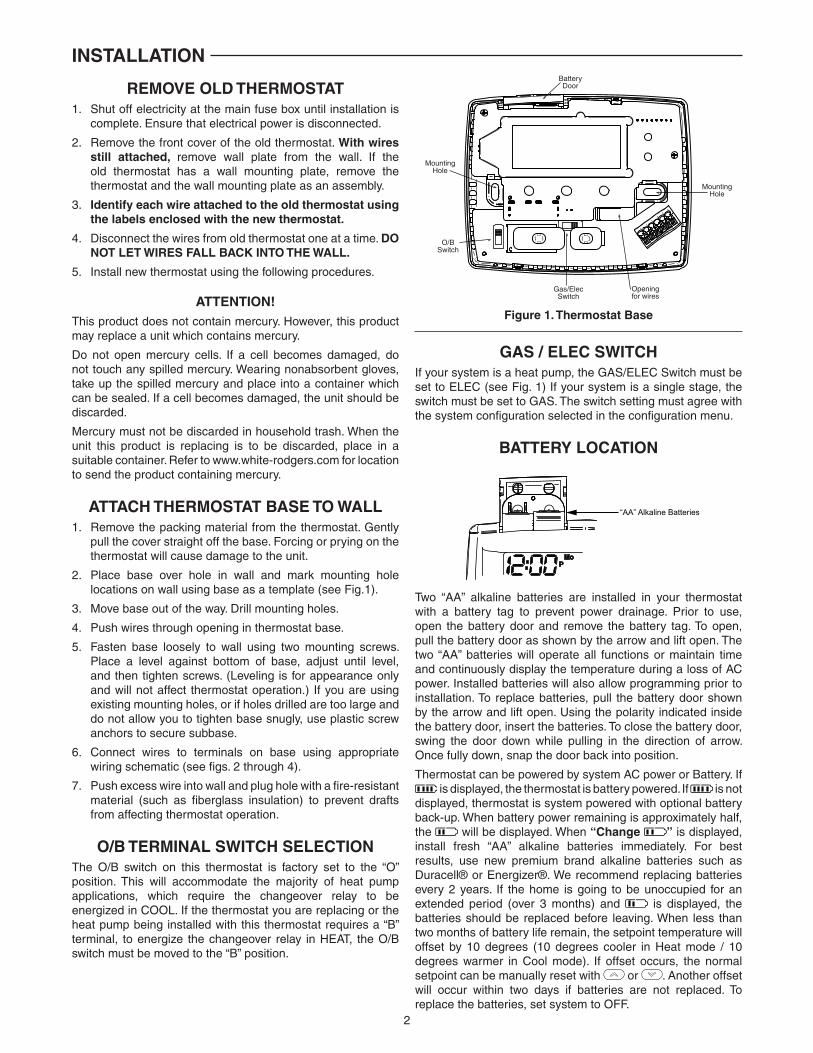
2. Remove the front cover of the old thermostat. With wires still attached, remove wall plate from the wall. If the old thermostat has a wall mounting plate, remove the thermostat and the wall mounting plate as an assembly.
3. Identify each wire attached to the old thermostat using the labels enclosed with the new thermostat.
4. Disconnect the wires from old thermostat one at a time. DO NOT LET WIRES FALL BACK INTO THE WALL.
5. Install new thermostat using the following procedures.
ATTENTION!This product does not contain mercury. However, this product may replace a unit which contains mercury.
Do not open mercury cells. If a cell becomes damaged, do not touch any spilled mercury. Wearing nonabsorbent gloves, take up the spilled mercury and place into a container which can be sealed. If a cell becomes damaged, the unit should be discarded.
Mercury must not be discarded in household trash. When the unit this product is replacing is to be discarded, place in a suitable container. Refer to www.white-rodgers.com for location to send the product containing mercury.
ATTACH THERMOSTAT BASE TO WALL1. Remove the packing material from the thermostat. Gently
pull the cover straight off the base. Forcing or prying on the thermostat will cause damage to the unit.
2. Place base over hole in wall and mark mounting hole locations on wall using base as a template (see Fig.1).
3. Move base out of the way. Drill mounting holes.
4. Push wires through opening in thermostat base.
5. Fasten base loosely to wall using two mounting screws. Place a level against bottom of base, adjust until level, and then tighten screws. (Leveling is for appearance only and will not affect thermostat operation.) If you are using existing mounting holes, or if holes drilled are too large and do not allow you to tighten base snugly, use plastic screw anchors to secure subbase.
6. Connect wires to terminals on base using appropriate wiring schematic (see fi gs. 2 through 4).
7. Push excess wire into wall and plug hole with a fi re-resistant material (such as fi berglass insulation) to prevent drafts from affecting thermostat operation.
O/B TERMINAL SWITCH SELECTIONThe O/B switch on this thermostat is factory set to the “O” position. This will accommodate the majority of heat pump applications, which require the changeover relay to be energized in COOL. If the thermostat you are replacing or the heat pump being installed with this thermostat requires a “B” terminal, to energize the changeover relay in HEAT, the O/B switch must be moved to the “B” position.
MountingHole
MountingHole
Openingfor wires
Gas/ElecSwitch
BatteryDoor
O/BSwitch
Figure 1. Thermostat Base
GAS / ELEC SWITCHIf your system is a heat pump, the GAS/ELEC Switch must be set to ELEC (see Fig. 1) If your system is a single stage, the switch must be set to GAS. The switch setting must agree with the system confi guration selected in the confi guration menu.
BATTERY LOCATION
“AA” Alkaline Batteries
Two “AA” alkaline batteries are installed in your thermostat with a battery tag to prevent power drainage. Prior to use, open the battery door and remove the battery tag. To open, pull the battery door as shown by the arrow and lift open. The two “AA” batteries will operate all functions or maintain time and continuously display the temperature during a loss of AC power. Installed batteries will also allow programming prior to installation. To replace batteries, pull the battery door shown by the arrow and lift open. Using the polarity indicated inside the battery door, insert the batteries. To close the battery door, swing the door down while pulling in the direction of arrow. Once fully down, snap the door back into position.
Thermostat can be powered by system AC power or Battery. If is displayed, the thermostat is battery powered. If is not
displayed, thermostat is system powered with optional battery back-up. When battery power remaining is approximately half, the will be displayed. When “Change ” is displayed, install fresh “AA” alkaline batteries immediately. For best results, use new premium brand alkaline batteries such as Duracell® or Energizer®. We recommend replacing batteries every 2 years. If the home is going to be unoccupied for an extended period (over 3 months) and is displayed, the batteries should be replaced before leaving. When less than two months of battery life remain, the setpoint temperature will offset by 10 degrees (10 degrees cooler in Heat mode / 10 degrees warmer in Cool mode). If offset occurs, the normal setpoint can be manually reset with or . Another offset will occur within two days if batteries are not replaced. To replace the batteries, set system to OFF.

3
ENERGY MANAGEMENT RECOVERY (EMR)
When the EMR feature is activated the thermostat’s microcomputer calculates the time it will take to change the room temperature to the next heat or cool program setting. Then the thermostat will start the system before the next programmed period so that the desired temperature is reached at or near the beginning of the period (the thermostat calculates 15 minutes for every 1°F temperature change). This feature provides better effi ciency by allowing gradual temperature changes.
For example: The thermostat is programmed to provide an overnight heating temperature of 66°F, and during the next program period, beginning at 6:00 AM, the programmed temperature is 70°F. With EMR activated, the thermostat will
automatically start the heating system at 5:00 AM, so that the programmed temperature of 70°F is reached by about 6:00 AM.
If the overnight room temperature drops only to 68°F, the thermostat will start the system at 5:30 to reach the programmed temperature of 70°F at 6:00.
The thermostat is shipped with the EMR feature active, which means that the thermostat will start the heating system before the beginning of the next program period.
To deactivate the EMR function, see the Confi guration menu on Page 5). The thermostat will then wait until the programmed time to start the system for a temperature change.
INSTALLATION
WIRING DIAGRAMS
RC
24 VAC 120 VAC
Hot
Neutral
THERMOSTAT
SYSTEMG W
Figure 2. Typical wiring diagram for single transformer single stage systems
TRANSFORMER
(Class II Current Limited)
ChangeoverRelay*
YO/B
CompressorContactor
* Changeover Relay is energized in COOL when O/B switch is in the “O” positionChangeover Relay is energized in HEAT when O/B switch is in the “B” position
Heat Relay
FanRelay Optional
Optional Jumper for Single Stage Heat Pump
RC
24 VAC 120 VAC
Hot
Neutral
THERMOSTAT
SYSTEMG W
Figure 3. Typical wiring diagram for two transformer single stage systems with NO safety circuits
TRANSFORMER
(Class II Current Limited)
ChangeoverRelay*
YO/B
CompressorContactor
* Changeover Relay is energized in COOL when O/B switch is in the “O” positionChangeover Relay is energized in HEAT when O/B switch is in the “B” position
Heat Relay
FanRelay Optional
Limit orSafety
Switches
TWO COMMONS MUSTBE JUMPERED TOGETHER!
HOT
NEUTRAL
120 VAC 24 VAC
CUT ANDTAPE OFF!
If safety circuits are in only one of the systems, remove the transformer of the system with NO safety circuits.
NOTE
Optional Jumper for Single Stage Heat Pump

4
WIRING DIAGRAMS
RCG W
Figure 4. Typical wiring diagram for two transformer single stage systems with safety circuits in BOTH systems
ChangeoverRelay*
YO/B
CompressorContactor
* Changeover Relay is energized in COOL when O/B switch is in the “O” positionChangeover Relay is energized in HEAT when O/B switch is in the “B” position
HeatRelay
FanRelay
Optional
TWO COMMONS MUSTBE JUMPERED TOGETHER!
24 VAC 120 VAC
HOT
NEUTRAL
THERMOSTAT
SYSTEM
HOT
NEUTRAL
120 VAC
Limit orSafety
Switches
Limit orSafety
Switches
Limit orSafety
Switches
24 VAC
Limit orSafety
Switches
COMMON
COMMON
AuxiliaryHeating
Transformer(Class II
Current Limited)
Heat Pump Transformer(Class II Current Limited)
24 VACACCESSORYRELAY N.O.CONTACT
Polarity must be observed. If the HOT side of the second transformer is jumpered to the COMMON side of the first transformer a short will be made. Damage to equipment will occur when power is restored.
NOTE
The accessory relay scheme is required when safety circuits exist in both systems.
NOTE
Optional Jumper for Single Stage Heat Pump
THERMOSTAT QUICK REFERENCE
Before you begin programming your thermostat, you should be familiar with its features and with the display and the location and operation of the thermostat buttons and switches (see fi g. 5). Your thermostat consists of two parts: the thermostat cover and the base. To remove the cover, pull it straight out from the base. To replace the cover, line up the cover with the base and press until the cover snaps onto the base.
The Thermostat Buttons and Switches1 Raises temperature setting.2 Lowers temperature setting.3 TIME button.4 SYSTEM switch (COOL, OFF, HEAT, EMER).5 PRGM (program) button.6 FAN switch (ON, AUTO).
7 RUN/HOLD (program) button.
The Display8 Indicates days of the week.9 Indicates setpoint temperature. This is blank when system
switch is in the OFF position. Setpoint temperature is displayed (fl ashing) if the thermostat is in lockout mode to prevent the compressor from cycling too quickly.
10 “Save” indicates the Cool Savings feature is enabled in the confi guration menu. “Save” (fl ashing) indicates Cool Savings feature is active.
11 Flame icon ( ) is displayed when the SYSTEM switch is in the HEAT position. Flame icon ( ) is displayed fl ashing when thermostat is calling for heat. Snowfl ake icon ( ) is displayed (non-fl ashing) when the SYSTEM switch is in the COOL position. Snowfl ake icon ( ) is displayed (fl ashing) if the thermostat is calling for cool.
12 Displays current temperature.
13 “Service” indicates a diagnostic fault in the heating/cooling system. It does not indicate a fault in the thermostat.
14 “Change Filter” is displayed when the system has run for the programmed fi lter time period as a reminder to change or clean your air fi lter.
15 “ ” indicates power level of batteries. “Change ” indicates batteries should be replaced.
16 Indicates time.
17 “A” “P” indicates time as Morning (A) Evening (P).
18 “Temp Hold” indicates temporary hold or “Hold” indicates hold mode.
Figure 5. Thermostat display, buttons, and switches
SYSTEM
2
1
3 4 5 6 7
816
9
10
111213
15
14
17 18

5
The confi guration menu allows you to set certain thermostat operating characteristics to your system or personal requirements. To enter the menu: Set your thermostat to OFF and press the and buttons simultaneously. The display will show the fi rst item in the confi guration menu. Press RUN/HOLD to change to the next menu item or press TIME to go backwards to the previous item in the menu. To exit the menu and return to the program operation, press PRGM. If no keys are pressed within fi fteen minutes, the thermostat will revert to normal operation.
Confi guration Menu
Menu Reference Number
PressKey
Displayed (FactoryDefault)
Press or to select from listed options
Comments
1 and SS HP Select Single Stage (SS) orHeat Pump (HP, 1 compressor)
2 RUN/HOLD* CS(OFF)
On Select Cool Savings Feature On or OFF
RUN/HOLD* CS(3)
1, 2, 3, 4, 5, 6 If CS selected On, selects Cool Savings value
3 RUN/HOLD* E(On)
OFF Select Energy Management Recovery On or OFF
4 RUN/HOLD* CR Heat(ME)
FA, SL Select Adjustable Anticipation, cycle rate, Heat Single Stage
5 RUN/HOLD* CR Cool(FA)
SL Select Adjustable Anticipation, cycle rate, Cool Single Stage
6 RUN/HOLD* CL(OFF)
On Select Compressor lockout OFF or On
7 RUN/HOLD* L(On)
OFF Select Display Light On or OFF
8 RUN/HOLD* Temp(0 HI)
4 LO to 4 HI
Select temperature display adjustment higher or lower
9 RUN/HOLD* oF oC Select oF / oC Display (temperature units in Fahrenheit or Celsius)
10 RUN/HOLD* Change Filter(OFF)
On Select fi lter replacement indicator OFF or On
RUN/HOLD* Change Filter(200 h)
25 to 1975 If Change Filter selected On, selects time interval for Change Filter Indicator. (in 25 hour increments)
11 RUN/HOLD* Returns to normal operation
*Press RUN/HOLD to advance to next item or TIME to move backwards to previous item
INSTALLER/CONFIGURATION MENU
1) System Confi guration - Selects SS (Single Stage) or HP (Heat Pump) operating mode. Default confi guration is SS. For Heat Pump operation choose HP.
2) Select CS (Cool Savings™) - With Cool Savings™ enabled, the thermostat will make small adjustments to the Setpoint temperature during periods of high demand to reduce cooling system running time and save energy. When the cooling system has been running for more than 20 minutes, humidity in the home will be lower and a higher setpoint temperature will feel comfortable. After 20 minutes of run time, the thermostat will start increasing the setpoint temperature in steps of less than one degree as the system continues to run. These adjustments will eventually cause the system to satisfy the thermostat and turn the system off to reduce the energy consumption. When the Cool Savings feature is active and making adjustments, the display will show “Save”. The amount of the adjustments to the setpoint temperature is dependent on the Cool Savings value that is set, 1 being the least adjustment and 6 being the most adjustment. With this feature set to OFF, no change will occur when the cooling system is continuously running during the periods of high demand. Periods of high demand will normally occur during the late afternoon and early evening on the hottest days of the summer.
3) Select Energy Management Recovery - Energy Management Recovery (E) On enables the thermostat to start heating or cooling early to make the building temperature reach the program setpoint at the time you specify. Heating will start 5 minutes early for every 1° of temperature required to reach setpoint. Example: E On is selected and your heating is programmed to 65o at night and 70o at 7AM. If the building temperature is 65o, the difference between 65o and 70o is 5o. Allowing 5 minutes per degree, the thermostat Setpoint will change to 70o at 6:35 AM. Cooling allows more time per degree, because it takes longer to reach set temperature.
4 & 5) Select Cycle Rate Selection - The factory default setting for Single Stage Heat is Medium Cycle (ME). For Single Stage Cool the default setting is fast (FA). To change cycle rate, press the and buttons.
The cycle rate differentials for different settings are:
MODE Fast Medium Slow
(FA) (ME) (SL)
SS Heat 0.6°F 0.8°F 1.2°F
SS Cool 1.2°F - 1.7°F

6
Cooling System
1. Move SYSTEM switch to COOL position.
2. Press to adjust thermostat setting below room temperature. The blower should come on immediately on high speed, followed by cold air circulation. However, if the setpoint temperature is fl ashing, the compressor lockout feature is operating (see Confi guration menu, item 6).
To prevent compressor and/or property damage, if the outdoor temperature is below 50oF, DO NOT operate the cooling system.
CAUTION!
Do not allow the compressor to run unless the compressor oil heaters have been operational for 6 hours and the system has not been operational for at least 5 minutes.
CAUTION!
6) Select Compressor Lockout CL OFF or ON - Selecting CL On will cause the thermostat to wait 5 minutes between cooling cycles. This is intended to help protect the compressor from short cycling. Some newer compressors already have a time delay built in and do not require this feature. Your compressor manufacturer can tell you if the lockout feature is already present in their system. When the thermostat compressor time delay occurs, it will fl ash the setpoint for up to fi ve minutes.
7) Select Backlight Display - The display backlight improves display contrast in low lighting conditions. When the “C” terminal is connected, selecting backlight CdL On will keep the light on continuously. Select backlight OFF will turn the light on momentarily when any key is pressed. When the “C” terminal is not connected, regardless of the backlight selection, the light will be on momentarily when any key is pressed.
INSTALLER/CONFIGURATION MENU
8) Select Temperature Display Adjustment 4 LO to 4 HI - Allows you to adjust the room temperature display up to 4° higher or lower. Your thermostat was accurately calibrated at the factory but you have the option to change the display temperature to match your previous thermostat. The current or adjusted room temperature will be displayed on the display.
9) Select F° or C° Readout - Changes the display readout to Celsius or Fahrenheit as required.
10) Select Filter Replacement Reminder and Set Run Time Select the “Change Filter” reminder On or OFF. If selected On, press RUN/HOLD to select the time period from 25 to 1975 hours in 25 hour increments. In a typical application, 200 hours (default) of run time is approximately 30 days. After the selected time of blower operation, the thermostat will display “Change Filter” as a reminder to change or clean your air fi lter. When “Change Filter” is displayed, press the RUN/HOLD button to clear the display and restart the time to the next fi lter change. A selection of OFF will cancel this feature.
OPERATION
CHECK THERMOSTAT OPERATIONIf at any time during testing your system does not operate properly, contact a qualifi ed service person.
Turn on power to the system.
Fan OperationIf your system does not have a G terminal connection, skip to Heating System.
1. Move fan switch to ON position. The blower should begin to operate.
2. Move fan switch to AUTO position. The blower should stop immediately.
Heating System1. Move SYSTEM switch to HEAT position. If the auxiliary
heating system has a standing pilot, be sure to light it.
2. Press to adjust thermostat setting to 1° above room temperature. The system should begin to operate.
3. Press to adjust temperature setting below room temperature. The heating system should stop operating.
MANUAL OPERATION• HOLD TEMPERATURE — With the SYSTEM switch set
to HEAT or COOL, momentarily press RUN/HOLD button. HOLD will be displayed. Use or to adjust the temperature. The thermostat will hold the room temperature at the selected setting until you press RUN/HOLD button to start program operation again.
• TEMPERATURE OVERRIDE (TEMPORARY HOLD) — Press or until the temperature you want is displayed. The thermostat will override current programming and keep the room temperature at the selected temperature for 2 hours or until the next program period begins. Then the thermostat will automatically revert to the program.
3. Press to adjust temperature setting above room temperature. The cooling system should stop operating.
7
PROGRAMMING
PROGRAMMING YOUR THERMOSTATThis section will help you plan your thermostat’s program to meet your needs. For maximum comfort and effi ciency, keep the following guidelines in mind when planning your program.
• When heating (cooling) your building, program the temperatures to be cooler (warmer) when the building is vacant or during periods of low activity.
• During early morning hours, the need for cooling is usually minimal.
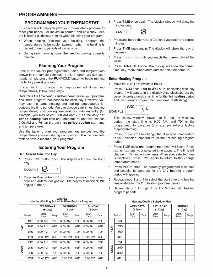
Planning Your ProgramLook at the factory preprogrammed times and temperatures shown in the sample schedule. If this program will suit your needs, simply press the RUN/HOLD button to begin running the factory preset program.
If you want to change the preprogrammed times and temperatures, follow these steps.
Determine the time periods and temperatures for your program. You must program four periods for each day. However, you may use the same heating and cooling temperatures for consecutive time periods. You can choose start times, heating temperatures, and cooling temperatures independently (for example, you may select 5:00 AM and 70° as the daily 1st period heating start time and temperature, and also choose 7:00 AM and 76° as the daily 1st period cooling start time and temperature).
Use the table to plan your program time periods and the temperatures you want during each period. Fill in the complete table to have a record of your programs.
Entering Your Program
Set Current Time and Day
1. Press TIME button once. The display will show the hour only.
EXAMPLE:
2. Press and hold either or until you reach the correct hour and AM/PM designation (AM begins at midnight; PM begins at noon).
3. Press TIME once again. The display window will show the minutes only.
EXAMPLE:
4. Press and hold either or until you reach the correct minutes.
5. Press TIME once again. The display will show the day of the week.
6. Press or until you reach the current day of the week.
7. Press RUN/HOLD once. The display will show the correct time, day, room temperature and set-point temperature.
Enter Heating Program1. Move the SYSTEM switch to HEAT.
2. Press PRGM once. “Mo Tu We Th Fr” (indicating weekday program) will appear in the display. Also displayed are the currently programmed start time for the 1st heating period and the currently programmed temperature (fl ashing).
EXAMPLE:
This display window shows that for the 1st weekday period, the start time is 6:00 AM, and 70° is the programmed temperature (this example refl ects factory preprogramming).
3. Press or to change the displayed temperature to your selected temperature for the 1st heating program period.
4. Press TIME once (the programmed time will fl ash). Press or until your selected time appears. The time will
change in 15 minute increments. When your selected time is displayed, press TIME again to return to the change temperature mode.
5. Press PRGM once. The currently programmed start time and setpoint temperature for the 2nd heating program period will appear.
6. Repeat steps 3 and 4 to select the start time and heating temperature for the 2nd heating program period.
7. Repeat steps 3 through 5 for the 3rd and 4th heating program periods.
SAMPLEHeating/Cooling Schedule Plan (Factory Program)
WEEKDAYS(5 Day)
SATURDAY(1 Day)
SUNDAY(1 Day)
StartTime Temp
StartTime Temp
StartTime Temp
1ST
2ND
3RD
4TH
1ST
2ND
3RD
4TH
Period
6:00 AM
8:00 AM
5:00 PM
10:00 PM
6:00 AM
8:00 AM
5:00 PM
10:00 PM
6:00 AM
8:00 AM
5:00 PM
10:00 PM
6:00 AM
8:00 AM
5:00 PM
10:00 PM
6:00 AM
8:00 AM
5:00 PM
10:00 PM
6:00 AM
8:00 AM
5:00 PM
10:00 PM
70F
62F
70F
62F
78F
85F
78F
82F
70F
62F
70F
62F
78F
85F
78F
82F
70F
62F
70F
62F
78F
85F
78F
82F
HE
AT
CO
OL
Heating/Cooling Schedule Plan
WEEKDAYS(5 Day)
SATURDAY(1 Day)
SUNDAY(1 Day)
StartTime Temp
StartTime Temp
StartTime Temp
1ST
2ND
3RD
4TH
1ST
2ND
3RD
4TH
Period
HE
AT
CO
OL

8
8. Press PRGM once. “SA” (indicating Saturday program) will appear in the display, along with the start time for the 1st heating period and the currently programmed temperature.
9. Repeat steps 3 through 7 to complete Saturday heating programming.
10. Press PRGM once to change to SU (Sunday) heating programming and repeat steps 3 through 7 to complete Sunday programming.
11. When you have completed entering your heating program, press RUN/HOLD.
Enter Cooling Program
1. Move SYSTEM switch to COOL position.
2. Follow Enter Heating Program for entering your cooling program, using your selected cooling times and temperatures.
PROGRAMMING
If the outside temperature is below 50oF, disconnect power to the cooling system before programming. Energizing the air conditioner compressor during cold weather may cause personal injury or property damage.
CAUTION!
CHECK YOUR PROGRAMMINGFollow these steps to check your thermostat programming one fi nal time before beginning thermostat operation.
1. Move SYSTEM switch to HEAT position.
2. Press PRGM to view the 1st weekday heating period time and temperature. Each time you press PRGM, the next heating period time and temperature will be displayed in sequence for weekday, then Saturday and Sunday program periods (you may change any time or temperature during this procedure).
3. Press RUN/HOLD.
4. Move SYSTEM switch to COOL position.
5. Repeat step 2 to check cooling program.
6. Move SYSTEM switch to HEAT or COOL and press RUN/HOLD to begin program operation.
YOUR THERMOSTAT IS NOW PROGRAMMED AND READY TO PROVIDE MAXIMUM COMFORT AND EFFICIENCY!

9
TROUBLESHOOTING
Reset OperationIf a voltage spike or static discharge blanks out the display or causes erratic thermostat operation, reset the thermostat by pressing the , and TIME buttons simultaneously.
If the thermostat has power, has been reset and still does not function correctly contact your heating/cooling service person or place of purchase.
Symptom Possible Cause Corrective Action
No Heat/No Cool/No Fan(common problems)
1. Blown fuse or tripped circuit breaker.2. Furnace power switch to OFF.3. Furnace blower compartment door or panel loose or not properly installed.
Replace fuse or reset breaker.Turn switch to ON.Replace door panel in proper position to engage safety interlock or door switch.
No Heat 1. System Switch not set to Heat.
2. Loose connection to thermostat or system3. Heating System requires service or thermostat requires replacement.
Set System Switch to Heat and raise setpoint above room temperature.Verify thermostat and system wires are securely attached.Diagnostic: Set System Switch to Heat and raise the setpoint above room temperature. Within a fi ve minutes the thermostat should make a soft slick sound. This sound usually indicates the thermostat is operating properly. If the thermostat does not click, try the reset operation listed above. If the thermostat does not click after being reset contact your heating and cooling service person or place of purchase for a replacement. If the thermostat clicks, contact the furnace manufac-turer or a service person to verify the heating system is operating correctly.
No Cool 1. System Switch not set to Cool.
2. Loose connection to thermostat or system.3. Cooling System requires service or thermostat requires replacement
Set System Switch to Cool and lower setpoint below room temperature.Verify thermostat and system wires are securely attached.Same procedures as diagnostic for No Heat condi-tion except set the thermostat to Cool and lower the setpoint below the room temperature. There may be up to a fi ve minute delay before the thermostat clicks in Cooling if the compressor lock-out option is selected in the confi guration menu (Item 6).
Heat, Cool or Fan Runs Constantly
1. Possible short in wiring.2. Possible short in thermostat.3. Possible short in Heat/Cool/Fan system.4. Fan Switch set to Fan On.
Check each wire connection to verify they are not shorted or touching together. No bare wire should stick out from under terminal screws. Try resetting the thermostat as described below. If the condition persists, the manufacturer of your system or service person can instruct you on how to test the Heat/Cool/ system for correct operation. If the system operates correctly, replace the thermostat.
Furnace Cycles Too Fast or Too Slow Cooling Cycles Too Fast or Too Slow (narrow or wide temperature swing)
1. The location of the thermostat and/ or the size of the Heating or Cooling System may be infl uencing the cycle rate.
Item 4 (CR Heat) or 5 (CR Cool) in the Confi guration Menu is the adjustment that controls the cycle rate. If an acceptable cycle rate is not achieved using the FA (Fast) or SL (Slow) adjustment contact a local service person for additional suggestions.
Thermostat Setting and Thermometer Disagree
1. Thermostat thermometer setting requires adjustment.
The thermometer can be adjusted +/- degrees as listed in item 8 of the Confi guration Menu. No other adjust-ment is possible.
Clock Loses or Gains Time 1. Loss of power to thermostat. The thermostat will maintain its program in memory even with no power but the clock time will be incorrect when power is restored. See No Heat/No Cool /No Fan (common problems) above for items to check in the system.
Heat or Cool Starts Early 1. EMR activated. See Confi guration Menu (Item 3)
Thermostat Does Not Follow Program
1. AM or PM set incorrectly in program.2. AM or PM set incorrectly on the clock.3. Voltage spike or static discharge.4. See “Heat or Cool Starts Early” above.
Check current clock and program settings including the AM or PM designations for each time period. If a voltage spike or static discharge occurs use the Reset Operation listed above.
Blank Display and/or Keypad Not Responding
1. Voltage Spike or Static Discharge. If a voltage spike or static discharge occurs use the Reset Operation listed above.

10
NOTES

11
NOTES

www.white-rodgers.com
White-Rodgers is a divisionof Emerson Electric Co.
The Emerson logo is a trademark and service markof Emerson Electric Co.
Homeowner Help Line: 1-800-284-2925