Embed Size (px)
Citation preview
SAUDI ARABIAN STANDARD SASO IEC 60669-2-1/2008
SAUDI STANDARD NO. SASO IEC 60669-2-1: 2008
SWITCHES FOR HOUSEHOLD AND SIMILAR FIXED ELECTRICAL INSTALLATIONS –
Part 2-1: Particular requirements –
Electronic switches
SAUDI ARABIAN STANDARDS ORGANIZATION THIS DOCUMENT IS A DRAFT SAUDI STANDARD CIRCULATED FOR COMMENTS. IT IS, THEREFORE, SUBJECT TO CHANGE AND MAY NOT BE REFERRED TO AS A SAUDI STANDARD UNTIL APPROVED BY THE BOARD OF DIRECTORS.

SAUDI ARABIAN STANDARD SASO IEC 60669-2-1/2008
1
CONTENTS FOREWORD ........................................................................................................................ 3 1 Scope ............................................................................................................................ 4 2 Normative references ..................................................................................................... 5 3 Definitions ...................................................................................................................... 6 4 General requirements ..................................................................................................... 9 5 General notes on tests ................................................................................................... 9 6 Rating .......................................................................................................................... 10 7 Classification ................................................................................................................ 10 8 Marking ........................................................................................................................ 11 9 Checking of dimensions ................................................................................................ 14 10 Protection against electric shock .................................................................................. 14 11 Provision for earthing ................................................................................................... 16 12 Terminals ..................................................................................................................... 16 13 Constructional requirements ......................................................................................... 17 14 Mechanism ................................................................................................................... 18 15 Resistance to ageing, protection provided by enclosures of switches,
and resistance to humidity ............................................................................................ 18 16 Insulation resistance and electric strength .................................................................... 18 17 Temperature rise .......................................................................................................... 19 18 Making and breaking capacity ....................................................................................... 22 19 Normal operation .......................................................................................................... 24 20 Mechanical strength ..................................................................................................... 27 21 Resistance to heat........................................................................................................ 27 22 Screws, current-carrying parts and connections ............................................................ 27 23 Creepage distances, clearances and distances through sealing compound ................... 27 24 Resistance of insulating material to abnormal heat, to fire and to tracking ..................... 29 25 Resistance to rusting .................................................................................................... 29 26 EMC requirements ........................................................................................................ 29 101 Abnormal conditions ..................................................................................................... 35 102 Components ................................................................................................................. 37 Annex A (normative) Survey of specimens needed for tests .............................................. 42 Annex B (normative) Additional requirements for switches having facilities for the outlet and retention of flexible cables .................................................................................. 43 Annex AA (informative) Examples of types of electronic switches and their functions ......... 44 Bibliography ....................................................................................................................... 45
SAUDI ARABIAN STANDARD SASO IEC 60669-2-1/2008
2
Figure 101 – Test pin for checking the protection against electric shock ................................ 9 Figure 102 – Circuit diagram for testing electronic switches according to 101.3 ................... 41 Table 101 – Number of specimens ...................................................................................... 10 Table 102 – Permissible temperature rise values (This table is based on table 3 of IEC 60065) ..................................................................................................................... 23 Table 103 – Relationship between rated current and capacitance ........................................ 26 Table 104 – Immunity tests ................................................................................................. 30 Table 105 – Voltage dip and short-interruption test values................................................... 30 Table 106 – Fast transient test values ................................................................................. 31 Table 107 – Capacitors ....................................................................................................... 39 Table B.1 – Maximum current and minimum cross-sectional area ........................................ 43
SAUDI ARABIAN STANDARD SASO IEC 60669-2-1/2008
3
FOREWORD
The Saudi Standards,Metrology and Quality Organization (SASO) has adopted the International Standard IEC 60669-2-1/2008 “SWITCHES FOR HOUSEHOLD AND SIMILAR FIXED ELECTRICAL INSTALLATIONS – Part 2-1: Particular requirements – Electronic switches ” issued by the International Electrotechnical Commission (IEC). It has been adopted without any technical modifications with a view to its approval as a Saudi standard.
SAUDI ARABIAN STANDARD SASO IEC 60669-2-1/2008
4
SWITCHES FOR HOUSEHOLD AND SIMILAR
FIXED ELECTRICAL INSTALLATIONS –
Part 2-1: Particular requirements – Electronic switches
1 Scope
This clause of part 1 applies except as follows.
Replacement:
This standard applies to electronic switches and to associated electronic extension units for household and similar fixed electrical installations either indoors or outdoors.
It applies to electronic switches for a.c. only, for the operation of lamp circuits and the control of the brightness of lamps (dimmers) as well as the control of the speed of motors (for example, those used in ventilating fans) and for other purposes (for example, heating controls), with a rated voltage not exceeding 250 V and a rated current not exceeding 16 A.
The operation and/or control as mentioned above are performed by a person via an actuating member, a sensing surface or a sensing unit, by means of touch, proximity, turn, optical, acoustic, thermal or any other influence.
This standard also applies to general purpose electronic switches with included automatic functions where the operation and/or the control is initiated by a change of a physical quantity, for example light, temperature, humidity, time, wind velocity, presence of persons, etc.
This standard also applies to boxes for electronic switches, with the exception of mounting boxes for flush-type electronic switches.
This standard also applies to electronic RCS and electronic TDS with a rated voltage not exceeding 440 V and a rated current not exceeding 25 A, intended for household and similar fixed electrical installations, either indoors or outdoors.
NOTE 1 Switches including only passive components such as resistors, capacitors, inductors, PTC and NTC components, varistors, printed wiring boards and connectors are not considered as electronic switches.
NOTE 2 Electronic switches may have control circuits with a.c. or d.c. rated control voltages.
Electronic switches complying with this standard are suitable for use at ambient temperature not normally exceeding 25 °C but occasionally reaching 35 °C.
In locations where special conditions prevail, such as in ships, vehicles and the like and in hazardous locations, for example, where explosions are liable to occur, special constructions may be required.
NOTE 3 This standard is not intended to cover devices which are designed to be incorporated in appliances or are intended to be delivered together with a specific appliance and which are within the scope of IEC 60730 or IEC 61058-1.
Examples of designs of electronic switches and functions are shown in annex AA.
SAUDI ARABIAN STANDARD SASO IEC 60669-2-1/2008
5
NOTE 4 Electronic switches without a mechanical switch in the main circuit do not provide a “full off-state”. Therefore, the circuit on the load side should be considered to be live.
SAUDI ARABIAN STANDARD SASO IEC 60669-2-1/2008
6
2 Normative references
This clause of part 1 applies except as follows.
Addition:
IEC 60065:2001, Audio, video and similar electronic apparatus – Safety requirements
IEC 60085:1984, Thermal evaluation and classification of electrical insulation
IEC 60127 (all parts), Miniature fuses
IEC 60227-5:1997, Polyvinyl chloride insulated cables of rated voltages up to and including 450/750 V – Part 5: Flexible cables (cords)1)
IEC 60317 (all parts), Specifications for particular types of winding wires
IEC 60317-0-1:1997, Specifications for particular types of winding wires – Part 0: General requirements – Section 1: Enamelled round copper wire1)
IEC 60384-14:1993, Fixed capacitors for use in electronic equipment – Part 14: Sectional specification: Fixed capacitors for electromagnetic interference suppression and connection to the supply mains
IEC 60664-1:2007, Insulation coordination for equipment within low-voltage systems – Part 1: Principles, requirements and tests
IEC 60664-3, Insulation coordination for equipment within low-voltage systems – Part 3: Use of coating, potting or moulding for protection against pollution
IEC 60669-2-2:2006, Switches for household and similar fixed electrical installations – Part 2-2: Particular requirements - Electromagnetic remote-control switches (RCS)
IEC 60669-2-3:2006, Switches for household and similar fixed electrical installations – Part 2-3: Particular requirements - Time-delay switches (TDS)
IEC 60730 (all parts), Automatic electrical controls for household and similar use
IEC 60998-2-1, Connecting devices for low-voltage circuits for household and similar purposes – Part 2-1: Particular requirements for connecting devices as separate entities with screw-type clamping units
IEC 61000-2-2:2002, Electromagnetic compatibility (EMC) – Part 2-2: Environment –Compatibility levels for low-frequency conducted disturbances and signalling in public low-voltage power supply systems
IEC 61000-3-2:2000, Electromagnetic compatibility (EMC) – Part 3-2: Limits – Limits for harmonic current emissions (equipment input current ≤ 16A per phase)1)
IEC 61000-3-3:1994, Electromagnetic compatibility (EMC) – Part 3: Limits – Section 3: Limitation of voltage fluctuations and flicker in low-voltage supply systems for equipment with rated current ≤ 16 A1)
IEC 61000-4-2:1995, Electromagnetic compatibility (EMC) − Part 4: Testing and measurement techniques − Section 2: Electrostatic discharge immunity test1)
IEC 61000-4-3:2002, Electromagnetic compatibility (EMC) − Part 4-3: Testing and measure-ment techniques − Radiated, radio-frequency, electromagnetic field immunity test
___________ 1) A consolidated version of this standard exists.
SAUDI ARABIAN STANDARD SASO IEC 60669-2-1/2008
7
IEC 61000-4-4:1995, Electromagnetic compatibility (EMC) − Part 4: Testing and measurement techniques − Section 4: Electrical fast transient/burst immunity test
IEC 61000-4-5:1995, Electromagnetic compatibility (EMC) − Part 4: Testing and measurement techniques − Section 5: Surge immunity test1)
IEC 61000-4-6:1996, Electromagnetic compatibility (EMC) − Part 4: Testing and measurement techniques − Section 6: Immunity to conducted disturbances, induced by radio-frequency fields1)
IEC 61000-4-8:1993, Electromagnetic compatibility (EMC) – Part 4: Testing and measurement techniques – Section 8: Power frequency magnetic field immunity test1)
IEC 61000-4-11:1994, Electromagnetic compatibility (EMC) − Part 4: Testing and measurement techniques − Section 11: Voltage dips, short interruptions and voltage variations immunity tests1)
IEC 61032, Protection of persons and equipment by enclosures – Probes for verification
IEC 61558-2-6, Safety of power transformers, power supply units and similar – Part 2: Particular requirements for safety isolating transformers for general use
CISPR 14 (all parts), Electromagnetic compatibility – Requirements for household appliances, electric tools and similar apparatus
CISPR 15:2000, Limits and methods of measurement of radio disturbance characteristics of electrical lighting and similar equipment
ISO 306:1994, Plastics – Thermoplastic materials – Determination of Vicat softening temperature (VST)
3 Definitions
This clause of part 1 applies with the following additions.
Addition, after the first paragraph: The term “electronic switch” is used as a general term to cover both electronic switching and control devices.
3.101 rated load load assigned to the electronic switch by the manufacturer
3.102 minimum load lowest load at which the electronic switch still operates correctly
3.103 minimum current lowest current at which the electronic switch still operates correctly
3.104 electromechanically operated contact mechanism component which operates the parts used to open and close the circuit electromechanically
___________ 1) A consolidated version of this standard exists.
SAUDI ARABIAN STANDARD SASO IEC 60669-2-1/2008
8
3.105 semiconductor switching device switching device designed to make or break the current in an electric circuit by means of the controlled conductivity of a semiconductor in that circuit
NOTE 1 In a circuit where the current passes through zero (periodically or otherwise) the effect of “not making” the current following such a zero value is equivalent to breaking the current.
NOTE 2 Typical examples of semiconductor switching devices are:
− electronic switching devices using the phase-cut-on principle to control the load by electronic switching on the current at any phase angle at or after zero crossing in each half-wave, for example, by a thyristor;
− electronic switches using the phase-cut-off principle to control the load by switching off the current at any phase angle after zero crossing in each half-wave, for example, by a transistor in a diode bridge.
3.106 electronic momentary contact switch electronic switch with an electromechanical switching mechanism or a semiconductor switching device which returns automatically to the initial state after operation
3.107 mechanical control unit unit directly adjustable by mechanical means (for example, potentiometer) which controls the output via electronic components
3.108 electronic output control unit unit adjustable by other than mechanical means (for example, sensing unit), containing electronic components and controlling the output via electronic components
3.109 electronic extension unit unit permitting the control of an electronic switch from a distance
3.110 protective impedance impedance connected between live parts and accessible conductive parts, of such value that the current, in normal use and under likely fault conditions in the electronic switch, is limited to a safe value, and which is so constructed that the reliability is maintained throughout the life of the electronic switch.
3.111 external flexible cable cable, a part of which is external to the electronic output control unit. NOTE Such cable may either be a supply cable or a connecting cable between separate parts of an accessory.
3.112 RCS remote controlled switch switch intended to be operated from a distance
3.112.1 electromagnetic RCS RCS provided with a coil which is operated by means of impulses or which may be permanently energized by means of a control circuit NOTE These devices are covered by IEC 60669-2-2.
SAUDI ARABIAN STANDARD SASO IEC 60669-2-1/2008
9
3.112.2 electronic RCS electronic switch providing the function, markings and connection configuration of an RCS according to IEC 60669-2-2, but containing electronic components and/or a combination of electronic components and a coil or coils, which is operated by means of an electronic extension unit or units NOTE This electronic RCS may for example be used as a look alike replacement for RCS according to IEC 60669-2-2.
3.113 rated control voltage the voltage assigned to the external control circuit by the manufacturer
3.114 switching circuit the circuit which contains the parts which allow the rated current to flow through the RCS or TDS
3.115 control circuit the circuit which includes electrical parts to actuate the switching mechanism
3.116 control mechanism mechanism which includes all the parts which are intended for the operation of the RCS or TDS
3.117 incorporated hand-operated device device incorporated in the switch which allows the switching circuit to be operated, directly or indirectly. This device is not intended for the normal operation of the RCS or TDS
3.118 rated control current current required for the initiation of the electronic RCS assigned to the control circuit by the manufacturer
3.119 bistable electronic RCS electronic RCS containing a control mechanism which, when not initiated electrically or actuated mechanically, remains stable in its operating position and will change its operating position on initiation or actuation
3.120 monostable electronic RCS electronic RCS containing a control mechanism which, on electrical initiation or mechanical actuation, changes the operating position of the switch which remains in this condition while the electronic RCS is initiated or actuated, and returns to the position prior to initiation or actuation of the electronic RCS after initiation or actuation is discontinued
3.121 priority electronic RCS electronic RCS used to operate directly or indirectly a first load circuit or group of load circuits the use of which at times can be dispensed with, and where the control circuit of the electronic RCS is influenced by or connected to a second circuit or group of circuits (priority or circuits) which when energized will thus initiate the control circuit of the electronic RCS to de-energize the first load circuit or circuits for the time during which the second circuit or group of circuits is energized
SAUDI ARABIAN STANDARD SASO IEC 60669-2-1/2008
10
NOTE The electronic RCS may have a means for adjusting the sensitivity of the electronic RCS control circuit to initiate the electronic RCS depending on the total load or current delivered to any part of the circuits (priority switch with current coil) or be sensitive to the voltage (priority switch with voltage coil) applied to the second load or group of loads.
3.122 TDS time delayed switch switch provided with a time-delay device which operates for a certain time (the delay time). It may be either manually actuated and/or remotely electrically initiated
3.123 electronic TDS electronic switch providing the function, markings and connection configuration of a TDS according to IEC 60669-2-3, but containing electronic components NOTE This electronic TDS may for example be used as a look alike replacement for TDS according to IEC 60669-2-3. 3.124 delay time period during which the switching circuit(s) is (are) kept closed. Any time taken for the decreasing of the voltage (e.g. to reduce the light) at the end of the delay period is included within the delay time
3.125 delay device all components which have an influence on the delay time. The delay time may be adjustable
4 General requirements
This clause of part 1 applies.
5 General notes on tests
This clause of part 1 applies except as follows.
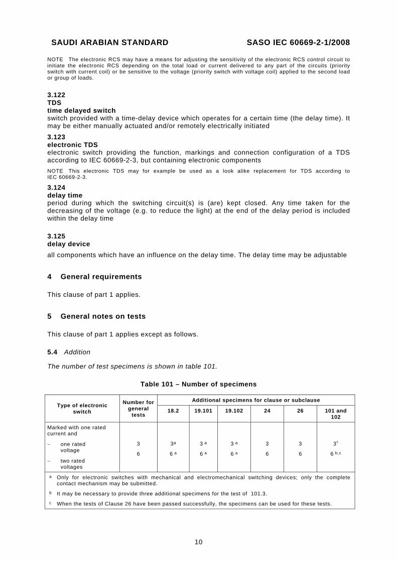
5.4 Addition
The number of test specimens is shown in table 101.
Table 101 – Number of specimens
Type of electronic switch
Number for general
tests
Additional specimens for clause or subclause
18.2 19.101 19.102 24 26 101 and 102
Marked with one rated current and
− one rated voltage
− two rated voltages
3
6
3a
6 a
3 a
6 a
3 a
6 a
3
6
3
6
3c
6 b,c
a Only for electronic switches with mechanical and electromechanical switching devices; only the complete contact mechanism may be submitted.
b It may be necessary to provide three additional specimens for the test of 101.3. c When the tests of Clause 26 have been passed successfully, the specimens can be used for these tests.
SAUDI ARABIAN STANDARD SASO IEC 60669-2-1/2008
11
5.101 All measurements shall be carried out by methods which are suitable for the purpose, which do not appreciably affect the values to be measured and which are not affected by factors such as waveform.
NOTE Care should be taken to use instruments giving true r.m.s. indications.
5.102 If the electronic circuitry is so enclosed that the short-circuiting or disconnecting of components is impossible or difficult, the manufacturer shall provide one additional test specimen with leads connected for measurements, short-circuiting, etc.
It is not necessary to connect leads to the interior of hybrid and monolith integrated circuits.
5.103 It may be necessary to disconnect electronic components for tests.
5.104 For electronic switches equipped with cut-outs, it may be necessary to provide three additional specimens for the test of 102.4.1.
5.105 If an electronic RCS or electronic TDS is provided with an incorporated hand-operated device, it shall be tested as specified in Clause 19.
NOTE 1 During the making and breaking capacity tests and the normal operation tests, switching at the same phase angle should be avoided, as this may give misleading results.
NOTE 2 Precautions should be taken when using combinations equipped with synchronous motors and similar operating devices.
5.106 In the case of an electronic TDS for which the control and the switching circuits have no common point, the test is made with the circuits supplied with the rated voltages which are declared by the manufacturer.
6 Rating
This clause of part 1 applies except as follows.
Replacement:
6.1 Preferred rated voltages are 110 V, 120 V, 130 V, 220 V, 230 V and 240 V.
6.2 This subclause of part 1 does not apply.
6.3 The preferred rated supply frequencies are 50 Hz and/or 60 Hz.
Addition:
For electronic RCS, Clause 6 of IEC 60669-2-2 is applicable.
For electronic TDS, Clause 6 of IEC 60669-2-3 is applicable.
7 Classification
7.1 This subclause of part 1 applies except as follows.
SAUDI ARABIAN STANDARD SASO IEC 60669-2-1/2008
12
7.1.1 Add the following new Addition:
Addition:
For electronic TDS, Subclause 7.1.1 of IEC 60669-2-3 applies.
7.1.5 Addition:
– touch; – proximity; – optical; – acoustic; – other external influences.
NOTE Actuating the electronic switch includes on/off operation, and/or regulating the brightness of lamps or speed of motors.
Addition:
For electronic RCS, Subclause 7.1.5 of IEC 60669-2-2 is applicable.
For electronic TDS, Subclause 7.1.5 of IEC 60669-2-3 is applicable.
7.1.6 Addition:
− electronic switches only intended to be mounted at a height greater than 1,7 m.
7.1.101 according to the kind of load intended to be controlled by the electronic switch:
− incandescent lamps; − fluorescent lamps; − motors; − declared load.
7.2 This subclause of part 1 does not apply.
7.101 For electronic RCS, Subclause 7.101 of IEC 60669-2-2 is applicable.
7.102 For electronic RCS, Subclause 7.102 of IEC 60669-2-2 is applicable.
7.103 Electronic RCS or electronic TDS having a SELV- or PELV-circuit.
8 Marking
This clause of part 1 applies except as follows.
8.1 Replacement:
Electronic switches shall be marked with
− rated voltage in volts; − rated current in amperes or rated load in volt-amperes or watts: − symbol for nature of supply;
SAUDI ARABIAN STANDARD SASO IEC 60669-2-1/2008
13
− manufacturer’s or responsible vendor’s name, trade mark or identification mark; − type reference, which may be a catalogue number; − symbol for mini-gap construction, if applicable; − symbol for micro-gap construction, if applicable; − symbol for semiconductor switching device, if applicable; − first characteristic numeral for the degree of protection against access to hazardous
parts and against harmful effects due to ingress of solid objects, if declared higher than 2, in which case the second characteristic numeral shall also be marked;
− second characteristic numeral for the degree of protection against harmful effects due to ingress of water, if declared higher than 0, in which case the first characteristic numeral shall also be marked.
NOTE 1 Marking of the pattern number given in 7.1.1 is recommended if the connections are not clear from an inspection of the electronic switch; this pattern number may be part of the type reference.
NOTE 2 If a base carries two or more electronic switches with separate operating devices, marking with the pattern numbers is recommended, for example 1+6 or 1+1+1.
NOTE 3 For electronic switches suitable for more than one type of rated load, see 8.3.
In addition, electronic switches shall be marked with
− rated frequency in hertz, unless the electronic switch is designed for both 50 Hz and 60 Hz;
− rating and type of any fuse incorporated in the electronic switch; − symbols for the kind of load (see 8.2); − the term “extension unit”, if applicable, or the relevant translation in the official
language(s) of the country in which the product is to be sold, followed by the identifying reference;
− the minimum height for mounting the electronic switch shall be indicated in the installation instruction of the manufacturer if there is a restriction (see 10.1).
In addition, electronic switches with screwless terminals shall be marked with an indication of the suitability to accept rigid conductors only, for those electronic switches having this restriction. This information may be put on the electronic switch and/or on the packaging unit.
For general purpose electronic switches with included automatic function the number of operations shall be stated in the accompanying instruction sheet when the manufacturer declares the number of operations is higher than indicated in Subclauses 19.101, 19.102 and 19.104.
In addition,
– for electronic RCS, Subclause 8.1 of IEC 60669-2-2 applies; – for electronic TDS, Subclause 8.1 of IEC 60669-2-3 applies.
8.2 Addition:
Volt-ampere .......................................................................................................... VA
Watt ................................................................................................................... W
Hertz ................................................................................................................... Hz
Terminal for regulated load ...................................................................................
Type of load:
Incandescent lamps ..............................................................................................
SAUDI ARABIAN STANDARD SASO IEC 60669-2-1/2008
14
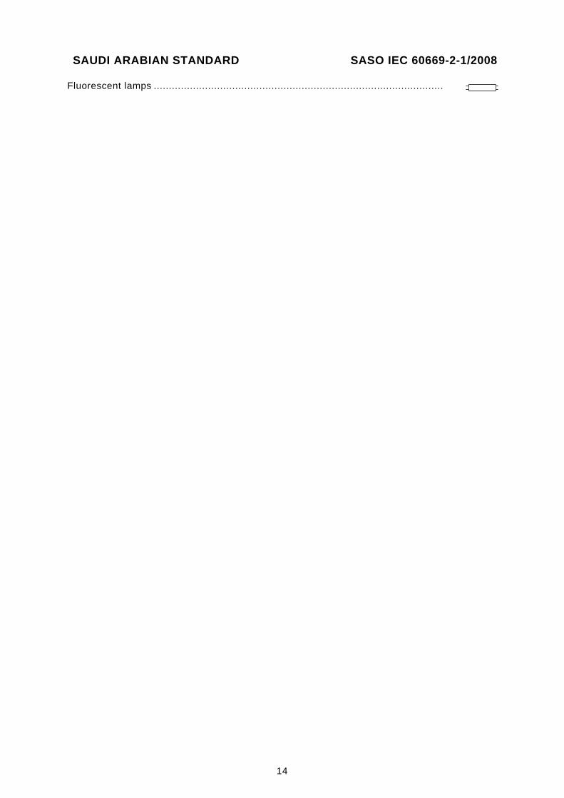
Fluorescent lamps ................................................................................................
SAUDI ARABIAN STANDARD SASO IEC 60669-2-1/2008
15
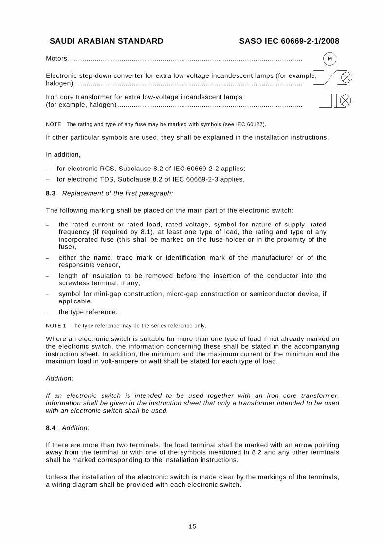
Motors ..................................................................................................................
Electronic step-down converter for extra low-voltage incandescent lamps (for example, halogen) ..............................................................................................................
Iron core transformer for extra low-voltage incandescent lamps (for example, halogen) ..........................................................................................
NOTE The rating and type of any fuse may be marked with symbols (see IEC 60127).
If other particular symbols are used, they shall be explained in the installation instructions.
In addition,
– for electronic RCS, Subclause 8.2 of IEC 60669-2-2 applies; – for electronic TDS, Subclause 8.2 of IEC 60669-2-3 applies.
8.3 Replacement of the first paragraph:
The following marking shall be placed on the main part of the electronic switch:
− the rated current or rated load, rated voltage, symbol for nature of supply, rated frequency (if required by 8.1), at least one type of load, the rating and type of any incorporated fuse (this shall be marked on the fuse-holder or in the proximity of the fuse),
− either the name, trade mark or identification mark of the manufacturer or of the responsible vendor,
− length of insulation to be removed before the insertion of the conductor into the screwless terminal, if any,
− symbol for mini-gap construction, micro-gap construction or semiconductor device, if applicable,
− the type reference.
NOTE 1 The type reference may be the series reference only.
Where an electronic switch is suitable for more than one type of load if not already marked on the electronic switch, the information concerning these shall be stated in the accompanying instruction sheet. In addition, the minimum and the maximum current or the minimum and the maximum load in volt-ampere or watt shall be stated for each type of load.
Addition:
If an electronic switch is intended to be used together with an iron core transformer, information shall be given in the instruction sheet that only a transformer intended to be used with an electronic switch shall be used.
8.4 Addition:
If there are more than two terminals, the load terminal shall be marked with an arrow pointing away from the terminal or with one of the symbols mentioned in 8.2 and any other terminals shall be marked corresponding to the installation instructions.
Unless the installation of the electronic switch is made clear by the markings of the terminals, a wiring diagram shall be provided with each electronic switch.
M
SAUDI ARABIAN STANDARD SASO IEC 60669-2-1/2008
16
In addition,
– for electronic RCS, Subclause 8.4 of IEC 60669-2-2 applies; – for electronic TDS, Subclause 8.4 of IEC 60669-2-3 applies.
8.6 Addition:
The off-state shall not be marked with an “O” if the circuit on the load side is considered as live, in accordance with clause 10.
8.6.101 It is recommended that the actual state of the electronic switch intended to control the brightness of lamps be indicated when used as intended. This can be achieved either
– with marking on the on-/off-state position, or – with an indicator lamp, or – by adjusting the lamp dimmer so that at the lowest control state and at rated voltage
minus 10 %, the light is still visible.
NOTE A test to verify that the light is still visible is under consideration.
When the indication of the electronic switch state is given only by the lamp, adjustment of the lamp at the lowest control state is made as specified in the following:
− for incandescent lamps, the adjustment of lamp dimmers shall be made by the manufacturer. It shall not be possible to reduce the lowest setting without a tool;
− for fluorescent lamps, the adjustment of lamp dimmers shall be made by the manufacturer. It may, however, be possible for the installer to alter the lowest setting if such an adjustment is indicated in an installation instruction.
8.8 Addition after the second paragraph:
If an electronic switch containing a viewing window (lens) for a sensing device is intended to be mounted at a height greater than 1,7 m, this information shall be stated in the instruction sheet.
Addition to note 2:
− information concerning external, directly associated fuses/current limiting devices, where applicable.
9 Checking of dimensions
This clause of part 1 applies except as follows.
Addition:
Electronic switches may be of dimensions other than those specified in the standard sheets (if any) provided they are supplied with suitable boxes.
10 Protection against electric shock
This clause of part 1 applies except as follows.
10.1 Addition:
NOTE 1 For the purpose of this standard, metal sensing surfaces which are connected to live parts by means of protective impedances (see 10.2) are not considered to be live parts.
SAUDI ARABIAN STANDARD SASO IEC 60669-2-1/2008
17
Replacement of the 6th and 7th paragraphs:
During this additional test, the electronic switches are subjected for 1 min to a force applied through the tip of test probe 11 of IEC 61032.
This probe, with an electrical indicator as described above, is applied with a force of 75 N to all places where yielding of the insulating material could impair the safety of the electronic switch, but is applied to thin-walled knock-outs with a force of 10 N.
Viewing windows or the like on electronic switches intended to be mounted at a height greater than 1,7 m are subjected to a force of 30 N.
The test probe is not applied to membranes and the like. These parts are tested according to 13.15.1.
NOTE 2 For the purposes of this standard, parts connected to a supply operating at SELV with a voltage up to and including 25 V a.c. or 60 V d.c. ripple free are not considered to be hazardous live parts.
10.2 Addition:
For touch sensitive electronic switches, the associated protective impedance does not have to comply with the requirements of clauses 16 and 23.
For electronic switches classified according to 7.1.4, first dash, accessible parts which are needed for the operation of electronic switches (for example, sensing surfaces) may be connected to live parts. If they are connected to live parts, it shall be by means of a protective impedance.
The protective impedance shall consist of at least two resistors or independent capacitors in series, of the same nominal value or a combination of both. The resistors shall comply with the requirements given in 102.3, and the capacitors shall comply with the requirements given in 102.2.
The removal of protective impedance shall only be possible by destruction of the electronic switch or by rendering it unusable.
Compliance is checked by inspection and by the following test.
The measurements are carried out between either a single accessible metal part or any combination of accessible metal parts and earth, through a non-inductive resistor of 2 kΩ at rated voltage (and rated load in on-state), in on- and off-state, and/or at lowest and highest setting values. During the measurements, each one of the resistors and all other components, if any, in the protective impedance, are alternatively short-circuited.
The current shall not exceed, in any measurement, 0,7 mA (peak value) for a.c. up to 1 kHz or 2 mA for d.c.
For frequencies above 1 kHz, the limit of 0,7 mA is multiplied by the value of the frequency in kilohertz, but shall not exceed 70 mA.
10.101 If a cover or cover-plate, or a fuse can be removed without the use of a tool, or if the installation instructions for the user indicate that, for the purpose of maintenance, when replacing the fuse, covers and cover-plates fastened by means of a tool have to be removed, the protection against contact with live parts shall be assured even after removal of the cover or cover-plate.
SAUDI ARABIAN STANDARD SASO IEC 60669-2-1/2008
18
This requirement does not apply when the electronic switch must be dismounted from its supporting means for the replacement of the fuse-link.
NOTE The conditions for the replacement of the fuse should be specified in the manufacturer’s instruction.
Compliance is checked by applying test probe B according to IEC 61032 with a force not exceeding 10 N. The test probe shall not touch live parts.
10.102 If an electronic switch is provided with a hole for adjusting the setting of the electronic and this hole is indicated as such, the adjustment shall not involve the risk of an electric shock.
Compliance is checked by applying a test pin according to figure 101 through the hole. The pin shall not touch live parts.
10.103 Ventilation openings over live parts shall be so designed that a foreign body introduced into these openings shall not come into contact with any live parts with the electronic switch installed as in normal use.
Compliance is checked by applying the test probe 13 of IEC 61032 through the openings. The pin of the test probe shall not touch live parts.
11 Provision for earthing
This clause of part 1 applies except as follows.
Addition:
This clause does not apply to SELV electronic switches.
12 Terminals
This clause of part 1 applies except as follows.
12.1 Addition to the end of the subclause:
NOTE The connecting capacity of terminals for other circuits than the main circuit (load circuit) is not in relation to the rated current of the electronic switch. That means that the terminals for the conductors to an external sensing unit may not necessarily have the same connecting capacity as the supply and load side terminals of the electronic switch.
Addition after the 3rd paragraph:
Terminals having screw clamping which are in compliance with IEC 60998-2-1 can be used.
Addition after the last paragraph:
Terminals having screw clamping complying with IEC 60998-2-1 are considered to be in compliance with the requirements and tests of Subclause 12.2, except those of 12.2.6 and 12.2.7 and 12.2.8, provided they are chosen according to Table 2.
12.2 Add the following new Addition:
Addition to note 2 of Table 2:
This requirement may be achieved using terminal(s) with two separate clamping units.
SAUDI ARABIAN STANDARD SASO IEC 60669-2-1/2008
19
13 Constructional requirements
This clause of part 1 applies except as follows.
13.4 Addition after the first paragraph:
Free openings according to 10.102 and 10.103 are accepted.
13.5 Replacement:
Knobs of electronic switches shall be securely fixed in a reliable manner so that they will not work loose in normal use, if loosening may result in a hazard.
If knobs are used to indicate the position of electronic switches, it shall not be possible to fix them in a wrong position, if this may result in a hazard.
Compliance is checked by inspection and by the following tests.
Where it is possible to apply an axial pull in normal use, an axial pull shall be applied for 1 min to try to pull off the knob.
The pull force to be applied is normally 15 N, but if the knob is intended to be pulled in normal use this is increased to 30 N.
An axial push of 30 N for 1 min is then applied to all knobs.
During and after these tests, the electronic switch shall show no damage, nor shall a knob have moved so as to impair compliance with this standard.
NOTE Sealing compound and the like, other than self-hardening resins are not considered to be adequate to prevent loosening.
13.15.1 Replacement: Membranes, lenses and the like shall be reliably fixed and shall not be displaced by the mechanical and thermal stresses occurring in normal use.
Compliance is checked by the following tests.
Membranes, lenses and the like are tested when assembled in the electronic switches.
First, the electronic switches are fitted with the membranes, lenses and the like which have been subjected to the treatment specified in 15.1.
The electronic switches are then placed for 2 h in a heating cabinet as described in 15.1, the temperature being maintained at (40 ± 2) °C.
Immediately after this period, a force of 30 N is applied for 5 s to various parts of the membranes, lenses and the like, by means of the tip of test probe 11 to IEC 61032.
During these tests, the membranes, lenses and the like shall not deform to such an extent that live parts become accessible.
For membranes, lenses and the like likely to be subjected to an axial pull in normal use, an axial pull of 30 N is applied for 5 s.
SAUDI ARABIAN STANDARD SASO IEC 60669-2-1/2008
20
During this test, the membranes, lenses and the like shall not come out.
The test is then repeated with membranes, lenses and the like which have not been subjected to any treatment.
13.101 Automatic protective devices incorporated in electronic switches for lamp circuits shall have at least micro-disconnection.
Cut-outs in electronic switches for motor speed control circuits shall be non-self-resetting.
Compliance is checked by inspection.
13.102 Electronic switches for the control of the voltage of iron core transformers for extra low- voltage incandescent lamps (for example, halogen) shall have a maximum tolerance of the phase-control angle between the positive and negative half-wave of ± 2°.
NOTE 1 Higher tolerances will generate a d.c. current influencing the temperature rise in the windings of the iron core transformer.
NOTE 2 The maximum tolerance between the phase-control angle of the positive and negative half-wave may be measured directly or as d.c. voltage in per cent of the rated voltage. This corresponds at 90° to 1,1 % of the peak value of the rated voltage.
Compliance is checked by measurement.
13.103 For electronic TDS, Subclause 13.101 of IEC 60669-2-3 applies.
14 Mechanism
This clause of part 1 only applies to electronic switches provided with mechanical switching devices.
14.101 For electronic RCS, Subclause 14.101 of IEC 60669-2-2 applies.
For electronic TDS, Subclause 14.101 of IEC 60669-2-3 applies.
15 Resistance to ageing, protection provided by enclosures of switches, and resistance to humidity
This clause of part 1 applies.
16 Insulation resistance and electric strength
This clause of part 1 applies except as follows.
Addition after the first paragraph:
Insulation resistance and electric strength are measured with the protective impedances according to 10.2 disconnected.
Addition to table 14:
NOTE 101 The test according to item 3 is carried out only on electronic switches combined with mechanical switches.
SAUDI ARABIAN STANDARD SASO IEC 60669-2-1/2008
21
Addition to Table 14:
9 Between switching circuit(s) and control circuit(s) if they are electrically separated 5 2 000 3 000
10 Between SELV/PELV circuits and other circuit(s) having a higher voltage than SELV/PELV 7 2 500 3 750
11 Between two SELV/PELV circuits 5 500 500
17 Temperature rise
This clause of part 1 applies except as follows.
Replacement:
Electronic switches shall be so constructed that the temperature rise in normal use is not excessive.
The metal and the design of the contacts, if any, shall be such that the operation of the electronic switch is not adversely affected by oxidation or any other deterioration.
The design and the material of the electronic switch shall be such that the material and the components in the electronic switch are not adversely affected by the temperature rise in normal use.
Compliance is checked by the following test, where applicable.
The electronic switches are fitted with the conductors as specified in table 15, the cross-sectional area being not less than 1,5 mm2; the terminal screws or nuts, if any, are tightened with a torque equal to two-thirds of that specified in 12.2.8.
Electronic switches for incandescent lamps (lamps rated for public supply voltage use) are loaded with lamps which have a rated value of 200 W (lamps of lower rated values and resistors, if any, may be used) so that, at rated voltage, the rated load will be obtained.
Electronic switches for fluorescent lamps and motors are loaded in accordance with the manufacturer's instructions.
Other electronic switches shall be loaded with the type of load as stated in the manufacturer’s instructions.
NOTE 1 The rated loads are verified with the electronic switch short-circuited.
For electronic TDS, Subclause 17.1 of IEC 60669-2-3 is applicable.
NOTE 2 If the electronic switch is intended to be loaded with different types of load, the test should be carried out with each type of load declared.
The electronic switches are loaded until steady-state temperature is reached at a voltage between 0,9 and 1,1 times rated voltage, whichever is the more unfavourable.
In lamp dimmers and speed controllers, the setting is adjusted such that the highest temperature rise will occur.
Flush-mounted electronic switches are mounted in flush-mounted boxes. The box is placed in a block of pinewood filled around the box with plaster, so that the front edge of the box does not protrude and is not more than 5 mm below the front surface of the pinewood block.
NOTE 3 The test assembly should be allowed to dry for at least seven days when first made.
SAUDI ARABIAN STANDARD SASO IEC 60669-2-1/2008
22
The size of the pinewood block, which may be fabricated from more than one piece, shall be such that there is at least 25 mm of wood surrounding the plaster, the plaster having a thickness between 10 mm and 15 mm around the maximum dimensions of the sides and rear of the box.
NOTE 4 The sides of the cavity in the pinewood block may have a cylindrical shape.
The cables connected to the electronic switch shall enter through the top of the box, the point(s) of entry being sealed to prevent the circulation of air. The length of each conductor within the box shall be (80 ± 10) mm.
Surface-type electronic switches shall be mounted as in normal use, centrally on the surface of a wooden block, which shall be at least 20 mm thick, 500 mm wide and 500 mm high.
The other types of electronic switches shall be mounted according to the manufacturer's instructions or, in the absence of such instructions, in the position of normal use considered to give the most onerous conditions.
The test assembly shall be placed in a draught-free environment for the test.
The temperature is determined by means of melting particles, colour-changing indicators or thermocouples, so chosen and positioned that they have negligible effect on the temperature being determined.
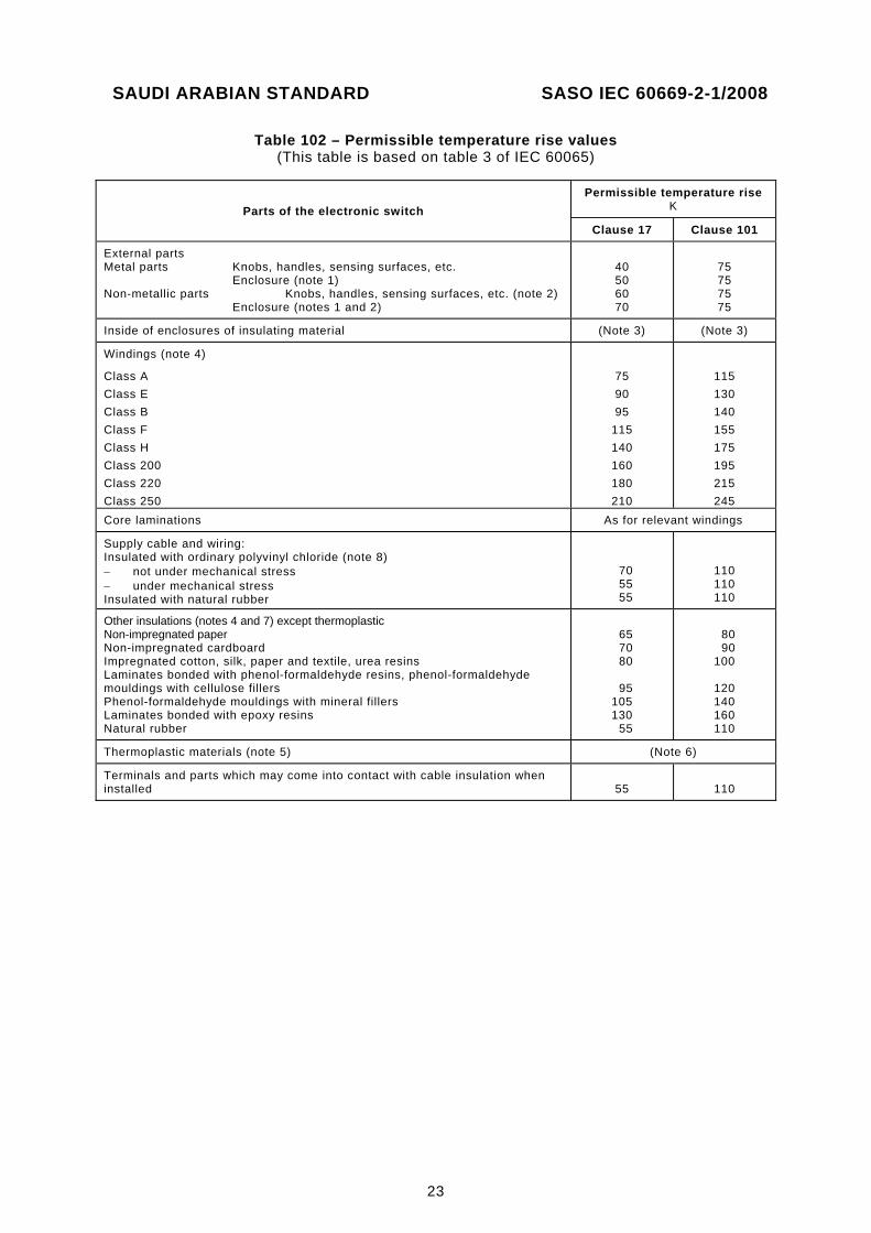
During the test, the electronic switch state shall not change, fuses and other protective devices shall not operate and the permissible temperature rises determined in table 102, column concerning clause 17, shall not be exceeded.
After this test, the electronic switch shall be in operating condition.
If sealing compounds are used, they shall not have flowed to such an extent that live parts are exposed.
Compliance is checked by inspection.
NOTE 5 For the purpose of the test of 21.3, the temperature rise of external parts of insulating material not necessary to retain current-carrying parts and parts of the earthing circuit in position, even though they are in contact with them, is also determined.
NOTE 6 Undue oxidation of contacts may be prevented by sliding action or by the use of silver or silver-faced contacts.
NOTE 7 Pellets of beeswax (melting-point 65 °C) with a diameter of 3 mm may be used as melting particles.
NOTE 8 In the case of combination of electronic switches, the test is carried out separately on each electronic switch.
For the purposes of the tests of 102.2, 102.3 and 102.4.1, the reference temperature surrounding a component in an electronic switch is the maximum temperature rise measured on the component during the test plus 25 °C.
SAUDI ARABIAN STANDARD SASO IEC 60669-2-1/2008
23
Table 102 – Permissible temperature rise values (This table is based on table 3 of IEC 60065)
Parts of the electronic switch Permissible temperature rise
K
Clause 17 Clause 101
External parts Metal parts Knobs, handles, sensing surfaces, etc. Enclosure (note 1) Non-metallic parts Knobs, handles, sensing surfaces, etc. (note 2) Enclosure (notes 1 and 2)
40 50 60 70
75 75 75 75
Inside of enclosures of insulating material (Note 3) (Note 3)
Windings (note 4)
Class A Class E Class B Class F Class H Class 200 Class 220 Class 250
75 90 95
115 140 160 180 210
115 130 140 155 175 195 215 245
Core laminations As for relevant windings
Supply cable and wiring: Insulated with ordinary polyvinyl chloride (note 8) − not under mechanical stress − under mechanical stress Insulated with natural rubber
70 55 55
110 110 110
Other insulations (notes 4 and 7) except thermoplastic Non-impregnated paper Non-impregnated cardboard Impregnated cotton, silk, paper and textile, urea resins Laminates bonded with phenol-formaldehyde resins, phenol-formaldehyde mouldings with cellulose fillers Phenol-formaldehyde mouldings with mineral fillers Laminates bonded with epoxy resins Natural rubber
65 70 80
95 105 130 55
80 90 100
120 140 160 110
Thermoplastic materials (note 5) (Note 6)
Terminals and parts which may come into contact with cable insulation when installed
55
110
SAUDI ARABIAN STANDARD SASO IEC 60669-2-1/2008
24
The values of the temperature rises are based on an ambient temperature of 25 °C, but the measurements are made under normal conditions.
NOTE 1 For areas not exceeding 5 cm2 and which are not likely to be touched in normal use, temperature rises up to 75 K are allowed under normal operating conditions.
NOTE 2 If these temperature rises are higher than those allowed by the class of the relevant insulating material, the nature of the material is the governing factor.
NOTE 3 The permissible temperature rises for the inside of enclosures of insulating material are those indicated for the relevant materials.
NOTE 4 For the purpose of this standard, the permissible temperature rises are based on the recommendations in IEC 60085. The materials quoted above are shown only as examples. If materials other than those listed in IEC 60085 are used, the maximum temperatures must not exceed those which have been proved to be satisfactory.
NOTE 5 Natural and synthetic rubbers are not considered as being thermoplastic materials.
NOTE 6 Due to their wide variety, it is not possible to specify permissible temperature rises for thermoplastic materials. While the matter is under consideration, the following method shall be used.
a) The softening temperature of the material is determined on a separate specimen, under the conditions specified in ISO 306, modified as follows:
− the depth of penetration is 0,1 mm;
− the total thrust of 10 N is applied before the dial gauge is set to zero or its initial reading noted.
b) The temperature limits to be considered for determining the temperature rises are:
− under normal operating conditions, a temperature 10 °C lower than the softening temperature as obtained under a);
− under fault conditions, the softening temperature itself.
NOTE 7 The table does not apply to components which comply with relevant IEC standards.
NOTE 8 The possibility of raising the values for wires and cables insulated with heat-resistant polyvinyl chloride is under consideration.
18 Making and breaking capacity
This clause of part 1 applies except as follows.
Replacement of the text before 18.1:
Electronic switches shall have adequate making and breaking capacity.
NOTE 1 Where the term “switch” is used in part 1, this term is replaced by “contact mechanism” as appropriate.
NOTE 2 In the case of electronic switches using relays, the relay is operated at the specified rate of operation with the appropriate load(s) as in normal use.
This test is carried out only on electronic switches provided with mechanically or electro-mechanically operated contact mechanisms.
Contact mechanisms shall have adequate making and breaking capacity.
The test is made on three separate specimens of the complete contact mechanism.
Compliance is checked by the following tests:
– for electronic switches for the control of fluorescent lamps loads, as specified in 18.1 of part 1;
– for electronic switches for the control of motor speed control circuits, as specified in 18.1 of part 1 and, additionally, in 18.101;
SAUDI ARABIAN STANDARD SASO IEC 60669-2-1/2008
25
– for electronic switches for the control of the voltage of iron core transformers for extra low-voltage incandescent lamps, as specified in 18.1, 18.2 of part 1 and 18.102;
– for electronic switches for the control of the voltage of electronic step-down converters for extra low-voltage incandescent lamps, as specified in 18.2 of part 1.
– for electronic switches for the control of other types of loads, as specified in 18.1 and 18.2 of part 1.
NOTE 3 For electronic switches whose cycle of operation is limited by their application (for example, passive infra-red, time delay electronic switches, etc.), the rate of operation during the tests may be specified by the manufacturer.
The tests are made by means of an apparatus the principle of which is shown in figure 12 and which is arranged to simulate normal operation.
The connections are as shown in figure 13.
Electronic switches are fitted with conductors as for the test of clause 17.
For electronic RCS, Clause 18 of IEC 60669-2-2 applies.
18.1 Addition after the second paragraph:
For electronic switches whose rate of operation is limited by their application (for example, heat or light sensors), the rate of operation is as follows. The electronic switch is set to the shortest cycle time possible. The electronic switch is re-activated at the end of each cycle within a time of (2 ± 0,5) s.
Addition:
For electronic TDS, Subclause 18.1, 2nd paragraph, of IEC 60669-2-3 applies at the following conditions:
For electronic TDS whose rate of operation is limited by their application (for example, heat or light sensors), the rate of operation is as follows. The electronic TDS is set to the shortest cycle time possible. The electronic switch is re-activated at the end of each cycle within a time of (2 ± 0,5) s.
All other electronic TDS are subjected to 200 operations at a uniform rate of
– 30 operations per minute if the rated current does not exceed 10 A; – 15 operations per minute if the rated current exceeds 10 A but is less than 25 A; – 7,5 operations per minute if the rated current is 25 A or more.
18.101 The contact mechanism is subjected to tests of 50 cycles of operation, each at rated voltage and at the rate of operations specified in 18.1 of part 1:
– the contact mechanism closes a circuit through which a current of 9 ln (cos ϕ = 0,8 ± 0,05) passes, this current being interrupted by means of an auxiliary switch 50 ms to 100 ms after each closure;
– the circuit through which a current of 6 ln (cos ϕ = 0,6 ± 0,05) passes is closed by an auxiliary switch and opened by the contact mechanism 300 ms to 500 ms after each closure.
NOTE 1 In is the rated current of the electronic switch.
NOTE 2 If the electronic switch has a rated load instead of a rated current, In is calculated under the assumption that the power factor (cos ϕ) of the motor load is 0,6.
During the tests, no sustained arcing shall occur.
After these tests, the specimens shall show no damage impairing their further use.
SAUDI ARABIAN STANDARD SASO IEC 60669-2-1/2008
26
18.102 Electronic switches for control of the voltage of iron core transformers for extra low-voltage incandescent lamps (for example, halogen) shall be subjected to the following test.
The test is made on three specimens.
The contact mechanism is subjected to 50 making operations, each at rated voltage and at the rate of operation as specified in 18.1 of part 1.
To simulate making, the test circuit shall be adjusted to a test current 10 times the rated current of the electronic switch for one half-cycle of the power supply frequency.
During the tests, no sustained arcing shall occur.
After the tests, the specimens shall show no damage impairing their further use.
NOTE Tests for electronic switches which can be operated with a transformer on no-load are under consideration.
19 Normal operation
This clause of part 1 applies except as follows.
Replacement:
Electronic switches shall withstand, without excessive wear or other harmful effect, the mechanical, electrical and thermal stresses occurring in normal use.
Compliance is checked by the tests of 19.101, 19.102, 19.103, 19.104 and 19.105, during which the electronic switches are tested at rated voltage and loaded as specified in clause 17, unless otherwise specified.
For general purpose electronic switches with included automatic function the number of operations for tests of Subclauses 19.101, 19.102 and 19.104 is that specified in the relevant subclause. If a manufacturer declares a number of operations higher than those indicated in the relevant subclause, the tests shall be made according to the declared value.
NOTE For the purpose of this test, the manufacturer can provide the specimens with a special circuit that simulates the automatic operations.
Electronic switches which are provided with connecting means for one or more electronic extension units are tested with one electronic extension unit connected, the connecting conductors being (1 ± 0,1) m long.
NOTE For electronic switches whose cycle of operation is limited by their applications (for example, passive infrared, time delay electronic switches, etc.), the rate of operation during the tests may be specified by the manufacturer.
For electronic RCS, Subclause 19.1 of IEC 60669-2-2 applies.
For electronic TDS, Subclause 19.1 of IEC 60669-2-3 applies.
During the test, the specimens shall function correctly.
After the tests, the specimen shall withstand the following:
− an electric strength test as specified in clause 16, the test voltage of 4 000 V being, however, reduced by 1 000 V and the other test voltages by 500 V, except for the specimens tested in 19.102 where no electric strength test is performed;
− a temperature rise test as specified in clause 17.
SAUDI ARABIAN STANDARD SASO IEC 60669-2-1/2008
27
The specimens shall then not show
– wear impairing their further use; – discrepancy between the position of the actuating member and that of the moving
contacts, if any, if the position of the actuating member is indicated; – deterioration of enclosures, insulating linings or barriers to such an extent that the
electronic switch cannot be further operated or that the requirements of clause 10 are no longer complied with;
– loosening of electrical or mechanical connections; – seepage of sealing compound; – relative displacement of the moving contacts of electronic switches of pattern number 2. NOTE 1 The humidity treatment according to 15.3 is not repeated before the electric strength test of this subclause.
NOTE 2 During the test, the specimens are not lubricated.
19.101 Contact mechanisms incorporated in electronic switches intended for incandescent lamp circuits are subjected to the following test.
The test is made on three separate specimens of the complete contact mechanism.
The circuit details and the manner of operation of the selector switch S are as described in 18.1, unless otherwise specified.
The number of operations is 40 000.
The rate of operation is as specified in 18.1.
For rotary electronic switches intended to be operated in either direction, the actuating member is turned in one direction for half the total number of operations and in the reverse direction for the remainder.
While testing one part, the other part is in the “off” position. The test is followed by the test of 14.3, if applicable.
Contact mechanisms incorporated in electronic switches intended for motor speed control circuits are tested as above, but they close a circuit through which a current of 6 × In (cos ϕ = 0,65 ± 0,05) passes and open a circuit through which a current of In (cos ϕ = 0,65 ± 0,05) passes, the ratio between recovery voltage Us and rated operational voltage Ue being 1,00 (±10 %).
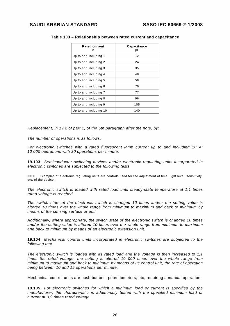
19.102 Contact mechanisms incorporated in electronic switches, intended for fluorescent lamp circuits or other capacitive loads (for example, electronic ballasts) are tested as in 19.2 of part 1 with the following modification.
This is not applicable to dimmers for step-down converters as these accessories are tested according to 19.101.
Replacement, in 19.2 of part 1, of the first dashed text by
– a capacitor bank C1, giving a capacitance according to table 103. The capacitors shall be connected with 2,5 mm² conductors having the shortest possible length;
SAUDI ARABIAN STANDARD SASO IEC 60669-2-1/2008
28
Table 103 – Relationship between rated current and capacitance
Rated current A
Capacitance µF
Up to and including 1 12
Up to and including 2 24
Up to and including 3 35
Up to and including 4 48
Up to and including 5 58
Up to and including 6 70
Up to and including 7 77
Up to and including 8 96
Up to and including 9 105
Up to and including 10 140
Replacement, in 19.2 of part 1, of the 5th paragraph after the note, by:
The number of operations is as follows.
For electronic switches with a rated fluorescent lamp current up to and including 10 A: 10 000 operations with 30 operations per minute.
19.103 Semiconductor switching devices and/or electronic regulating units incorporated in electronic switches are subjected to the following tests.
NOTE Examples of electronic regulating units are controls used for the adjustment of time, light level, sensitivity, etc, of the device.
The electronic switch is loaded with rated load until steady-state temperature at 1,1 times rated voltage is reached.
The switch state of the electronic switch is changed 10 times and/or the setting value is altered 10 times over the whole range from minimum to maximum and back to minimum by means of the sensing surface or unit.
Additionally, where appropriate, the switch state of the electronic switch is changed 10 times and/or the setting value is altered 10 times over the whole range from minimum to maximum and back to minimum by means of an electronic extension unit.
19.104 Mechanical control units incorporated in electronic switches are subjected to the following test.
The electronic switch is loaded with its rated load and the voltage is then increased to 1,1 times the rated voltage, the setting is altered 10 000 times over the whole range from minimum to maximum and back to minimum by means of its control unit, the rate of operation being between 10 and 15 operations per minute.
Mechanical control units are push buttons, potentiometers, etc, requiring a manual operation.
19.105 For electronic switches for which a minimum load or current is specified by the manufacturer, the characteristic is additionally tested with the specified minimum load or current at 0,9 times rated voltage.
SAUDI ARABIAN STANDARD SASO IEC 60669-2-1/2008
29
The switch state of the electronic switch is changed 10 times and/or the setting value is altered 10 times over the whole range from minimum to maximum and back to minimum.
In addition, where appropriate, the switch state of the electronic switch is changed 10 times and/or the setting value is altered 10 times over the whole range from minimum to maximum and back to minimum by means of an electronic extension unit.
19.106 For electronic RCS, Subclause 19.101 of IEC 60669-2-2 applies.
For electronic TDS, Subclause 19.101 of IEC 60669-2-3 applies.
19.107 For electronic TDS, Subclause 19.102 of IEC 60669-2-3 applies.
19.108 For electronic TDS, Subclause 19.103 of IEC 60669-2-3 applies.
20 Mechanical strength
This clause of part 1 applies.
21 Resistance to heat
This clause of part 1 applies.
22 Screws, current-carrying parts and connections
This clause of part 1 applies.
23 Creepage distances, clearances and distances through sealing compound
This clause of part 1 applies except as follows.
Addition:
The values given in items 1, 2, 6 and 7 of table 20 apply to terminals for external wiring and do not apply to other live parts which are protected by a directly associated fuse with adequate breaking capacity or other current-limiting means, under the provision that the requirements of clause 101 are fulfilled. If there is no directly associated fuse, or other current-limiting means, the electronic switch shall comply with table 20.
NOTE 1 Directly associated fuses and current-limiting means are devices inserted in the circuit whose primary function is to protect the electronic switch.
NOTE 2 A directly associated fuse and/or current-limiting means need not necessarily be incorporated in the electronic switch.
SAUDI ARABIAN STANDARD SASO IEC 60669-2-1/2008
30
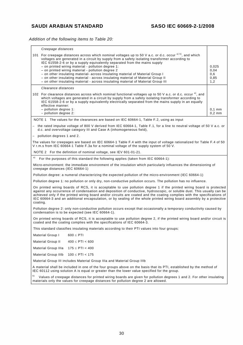
Addition of the following items to Table 20:
Creepage distances
101 For creepage distances across which nominal voltages up to 50 V a.c. or d.c. occur a) b), and which voltages are generated in a circuit by supply from a safety isolating transformer according to IEC 61558-2-6 or by a supply equivalently separated from the mains supply – on printed wiring material - pollution degree 1: – on printed wiring material - pollution degree 2 – on other insulating material- across insulating material of Material Group I – on other insulating material - across insulating material of Material Group II – on other insulating material - across insulating material of Material Group III
0,025 0,04 0,6 0,85 1,2
Clearance distances
102 For clearance distances across which nominal functional voltages up to 50 V a.c. or d.c. occur a), and which voltages are generated in a circuit by supply from a safety isolating transformer according to IEC 61558-2-6 or by a supply equivalently electrically separated from the mains supply in an equally effective manner: – pollution degree 1: – pollution degree 2:
0,1 mm 0,2 mm
NOTE 1 The values for the clearances are based on IEC 60664-1, Table F.2, using as input
– the rated impulse voltage of 800 V derived from IEC 60664-1, Table F.1, for a line to neutral voltage of 50 V a.c. or d.c. and overvoltage category III and Case A (inhomogeneous field),
– pollution degrees 1 and 2.
The values for creepages are based on IEC 60664-1 Table F.4 with the input of voltage rationalized for Table F.4 of 50 V r.m.s from IEC 60664-1 Table F.3a for a nominal voltage of the supply system of 50 V.
NOTE 2 For the definition of nominal voltage, see IEV 601-01-21. a) For the purposes of this standard the following applies (taken from IEC 60664-1):
Micro-environment: the immediate environment of the insulation which particularly influences the dimensioning of creepage distances (IEC 60664-1)
Pollution degree: a numeral characterizing the expected pollution of the micro-environment (IEC 60664-1)
Pollution degree 1: no pollution or only dry, non-conductive pollution occurs. The pollution has no influence.
On printed wiring boards of RCS, it is acceptable to use pollution degree 1 if the printed wiring board is protected against any occurrence of condensation and deposition of conductive, hydroscopic, or soluble dust. This usually can be achieved only if the printed wiring board and/or circuits are coated and the coating complies with the specifications of IEC 60664-3 and an additional encapsulation, or by sealing of the whole printed wiring board assembly by a protective coating.
Pollution degree 2: only non-conductive pollution occurs except that occasionally a temporary conductivity caused by condensation is to be expected (see IEC 60664-1).
On printed wiring boards of RCS, it is acceptable to use pollution degree 2, if the printed wiring board and/or circuit is coated and the coating complies with the specifications of IEC 60664-3.
This standard classifies insulating materials according to their PTI values into four groups:
Material Group I 600 ≤ PTI
Material Group II 400 ≤ PTI < 600
Material Group IIIa 175 ≤ PTI < 400
Material Group IIIb 100 ≤ PTI < 175
Material Group III includes Material Group IIIa and Material Group IIIb
A material shall be included in one of the four groups above on the basis that its PTI, established by the method of IEC 60112 using solution A is equal or greater than the lower value specified for the group. b) Values of creepage distances for printed wiring boards are given for pollution degrees 1 and 2. For other insulating materials only the values for creepage distances for pollution degree 2 are allowed.
SAUDI ARABIAN STANDARD SASO IEC 60669-2-1/2008
31
23.101 For electronic switches having a control circuit suitable for connection to a SELV supply, the switching circuit being supplied with a voltage greater than the SELV, creepage distances and clearances between control and switching circuits shall not be less than 5,5 mm.
In case of electronic RCS and electronic TDS classified according to 7.103, see the relevant requirements in IEC 60669-2-2 and IEC 60669-2-3 for clearance and creepage distances between SELV and mains.
23.102 If the enamel of the wire is at least grade 1 according to the IEC 60317 series, the clearances between the wire of the control coil, the live parts of different polarity and exposed conductive parts may be reduced to a value equal to two-thirds of the clearances required in the absence of enamel.
24 Resistance of insulating material to abnormal heat, to fire and to tracking
This clause of part 1 applies.
25 Resistance to rusting
This clause of part 1 applies.
26 EMC requirements
This clause of part 1 applies except as follows.
Replacement:
Electronic switches shall be designed to operate correctly under the conditions of electromagnetic environment in which they are intended to be used. This applies particularly for electronic switches intended to be connected to a.c. low-voltage public supply systems where the design shall take into account the normal disturbances on the supply system, as defined by the compatibility levels given in IEC 61000-2-2.
The tests are carried out with three new specimens (see table 101).
For electronic switches, the manufacturer shall specify all details related to the load.
Compliance is checked by the tests of 26.1 and 26.2.
26.1 Immunity
Electronic switches shall be designed so that the switch state (on or off) and/or the setting value are protected against interference.
For the following tests, the electronic switch is mounted as in normal use in the relevant box, if any, as specified by the manufacturer and is loaded as specified in clause 17 so that, at the rated voltage, the rated load will be obtained.
For the purpose of this test, the electronic switch is set to the measured or calculated value of the output power (r.m.s).
A variation of less than ± 10 % is not considered to be a change of the setting.
SAUDI ARABIAN STANDARD SASO IEC 60669-2-1/2008
32
Each electronic switch is tested, if applicable, in the following states:
a) in the on-state, highest setting, b) in the on-state, lowest setting, c) in the off-state.
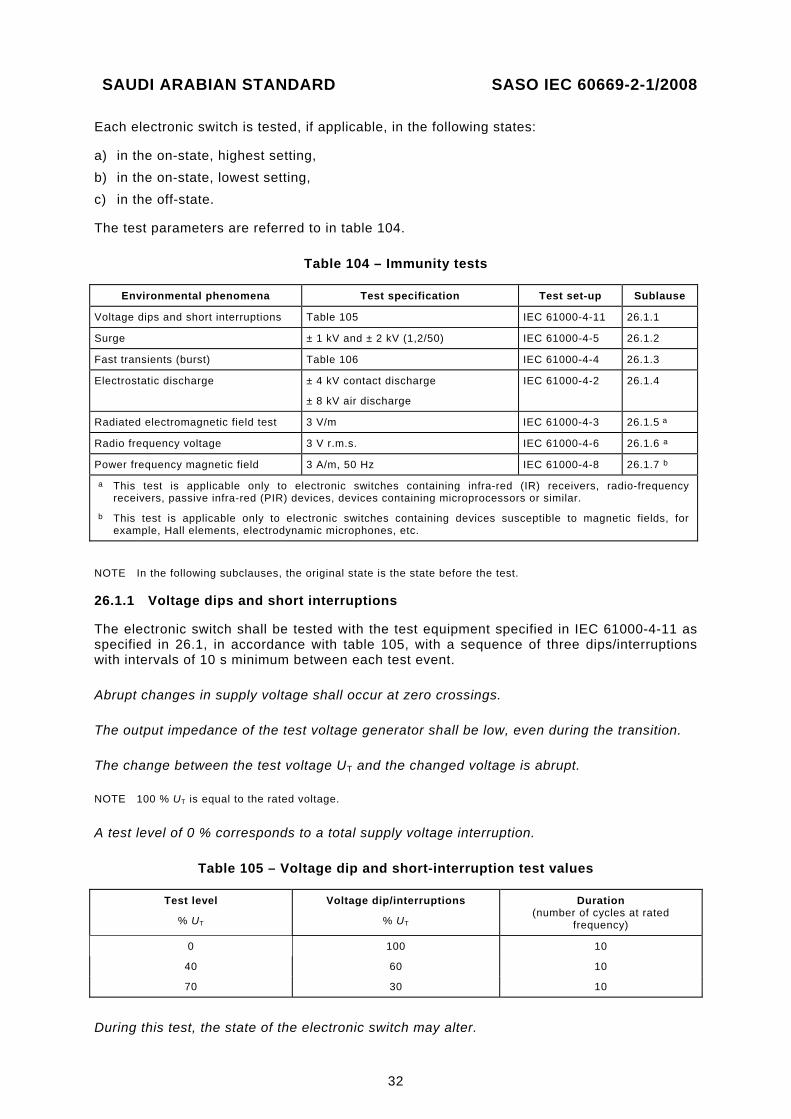
The test parameters are referred to in table 104.
Table 104 – Immunity tests
Environmental phenomena Test specification Test set-up Sublause
Voltage dips and short interruptions Table 105 IEC 61000-4-11 26.1.1
Surge ± 1 kV and ± 2 kV (1,2/50) IEC 61000-4-5 26.1.2
Fast transients (burst) Table 106 IEC 61000-4-4 26.1.3
Electrostatic discharge ± 4 kV contact discharge
± 8 kV air discharge
IEC 61000-4-2 26.1.4
Radiated electromagnetic field test 3 V/m IEC 61000-4-3 26.1.5 a
Radio frequency voltage 3 V r.m.s. IEC 61000-4-6 26.1.6 a
Power frequency magnetic field 3 A/m, 50 Hz IEC 61000-4-8 26.1.7 b
a This test is applicable only to electronic switches containing infra-red (IR) receivers, radio-frequency receivers, passive infra-red (PIR) devices, devices containing microprocessors or similar.
b This test is applicable only to electronic switches containing devices susceptible to magnetic fields, for example, Hall elements, electrodynamic microphones, etc.
NOTE In the following subclauses, the original state is the state before the test.
26.1.1 Voltage dips and short interruptions
The electronic switch shall be tested with the test equipment specified in IEC 61000-4-11 as specified in 26.1, in accordance with table 105, with a sequence of three dips/interruptions with intervals of 10 s minimum between each test event.
Abrupt changes in supply voltage shall occur at zero crossings.
The output impedance of the test voltage generator shall be low, even during the transition.
The change between the test voltage UT and the changed voltage is abrupt.
NOTE 100 % UT is equal to the rated voltage.
A test level of 0 % corresponds to a total supply voltage interruption.
Table 105 – Voltage dip and short-interruption test values
Test level
% UT
Voltage dip/interruptions
% UT
Duration (number of cycles at rated
frequency)
0 100 10
40 60 10
70 30 10
During this test, the state of the electronic switch may alter.
SAUDI ARABIAN STANDARD SASO IEC 60669-2-1/2008
33
Occasional flickering of lamps or irregular running of motors during the test is neglected.
After the test, the electronic switch shall be in the original state and the setting shall be unchanged.
After the test, the general purpose electronic switch with included automatic functions shall operate as intended.
26.1.2 Surge immunity test for 1,2/50 wave impulses
Electronic switches shall be tested for resistance to unidirectional surges caused by overvoltages from switching and lightning transients.
The test is carried out according to IEC 61000-4-5 by applying two positive discharges and two negative discharges at each of the following angles 0°, 90°, 270°, at a repetition rate of (60 ± 5) s with an open-circuit test voltage of 1 kV (level 2).
If the product has a metallic mounting surface when mounted as in normal use, the test is repeated between line and earth with a test voltage of 2 kV.
During the test, the state of the electronic switch may alter.
Occasional flickering of lamps or irregular running of motors during the test is neglected.
After the test, the electronic switch shall be in the original state and the setting shall be unchanged.
After the test, the general purpose electronic switch with included automatic functions shall operate as intended.
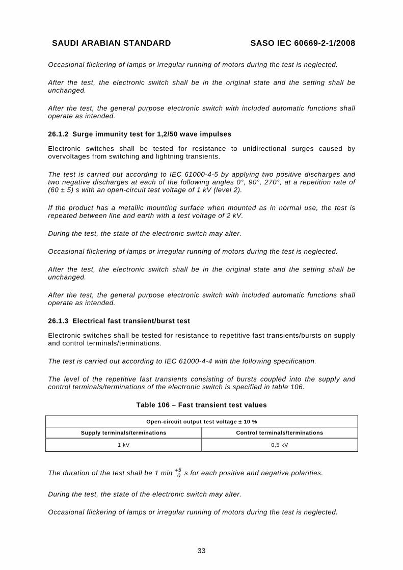
26.1.3 Electrical fast transient/burst test
Electronic switches shall be tested for resistance to repetitive fast transients/bursts on supply and control terminals/terminations.
The test is carried out according to IEC 61000-4-4 with the following specification.
The level of the repetitive fast transients consisting of bursts coupled into the supply and control terminals/terminations of the electronic switch is specified in table 106.
Table 106 – Fast transient test values
Open-circuit output test voltage ± 10 %
Supply terminals/terminations Control terminals/terminations
1 kV 0,5 kV
The duration of the test shall be 1 min 05+ s for each positive and negative polarities.
During the test, the state of the electronic switch may alter.
Occasional flickering of lamps or irregular running of motors during the test is neglected.
SAUDI ARABIAN STANDARD SASO IEC 60669-2-1/2008
34
After the test, the electronic switch shall be in the original state and the setting shall be unchanged.
After the test, the general purpose electronic switch with included automatic functions shall operate as intended.
26.1.4 Electrostatic discharge test
Electronic switches mounted as in normal use shall withstand electrostatic contact and air discharges. The test shall be carried out with incandescent lamps. If the electronic switch is not intended to operate incandescent lamps, the test shall be carried out with only one load of the loads specified within the manufacturer’s instructions.
The test is carried out according to IEC 61000-4-2 by applying 10 positive and 10 negative discharges in the following manner:
– contact discharge to the conductive surfaces and to coupling planes, – air discharge at insulating surfaces, if applicable.
The static electricity discharges shall be applied only to such points and surfaces of the electronic switch which are accessible in normal use.
The discharges are applied to the pre-selected points designated by the manufacturer, which shall include different material, if any.
The following levels apply:
– test voltage of contact discharge: 4 kV, – test voltage of air discharge: 8 kV.
During the test, the state of the electronic switch may alter.
Occasional flickering of lamps or irregular running of motors during the test is neglected.
After the test, the electronic switch shall be in its original state and the setting shall be unchanged.
After the test for electronic switches with a sensing surface intended to be operated by touch, the state and/or setting may be altered, but it shall be possible to operate the electronic switch as intended.
NOTE Certain electronic switches, for example, passive infra-red switches, PIR switches with an adjustable time delay device should be adjusted in such a way that the time delay is higher than the testing time.
After the test, the general purpose electronic switch with included automatic functions shall operate as intended.
26.1.5 Radiated electromagnetic field test
This test is applicable only to electronic switches containing infra-Rrd (IR) receivers, radio- frequency receivers, passive infra-red (PIR) devices, devices containing microprocessors or similar.
Electronic switches shall withstand the radiated electromagnetic field test.
The test is carried out according to IEC 61000-4-3 by applying a field strength of 3 V/m in the frequency range 80 MHz to 1 000 MHz.
SAUDI ARABIAN STANDARD SASO IEC 60669-2-1/2008
35
During the test, the state of the electronic switch shall not change.
Flickering of lamps or irregular running of motors during the test is not allowed. Flickering of lamps or irregular running of motors due to switching transients caused by frequency changes of the test equipment during the test procedure is neglected.
After the test, the electronic switch shall be in the original state and the setting shall be unchanged.
In case of electronic time delay switches, the switch shall be in the original state after the time delay.
After the test, the general purpose electronic switch with included automatic functions shall operate as intended.
26.1.6 Radio-frequency voltage test
This test is applicable only to electronic switches containing infra-red (IR) receivers, radio- frequency receivers, passive infra-red (PIR) devices, devices containing microprocessors or similar.
Electronic switches shall withstand the radio-frequency voltage test.
The test is carried out according to IEC 61000-4-6 by applying a conducted radio-frequency voltage of 3 V r.m.s. on supply lines and control lines.
During the test, the state of the electronic switch shall not change.
Flickering of lamps or irregular running of motors during the test is not allowed. Flickering of lamps or irregular running of motors due to switching transients caused by frequency changes of the test equipment during the test procedure is neglected.
After the test, the electronic switch shall be in the original state and the setting shall be unchanged.
After the test, the general purpose electronic switch with included automatic functions shall operate as intended.
26.1.7 Power-frequency magnetic field test
This test is applicable only to electronic switches containing devices susceptible to magnetic fields, for example, Hall elements, electrodynamic microphones, etc.
Electronic switches shall withstand the power frequency magnetic field test.
The test is carried out according to IEC 61000-4-8 by applying a magnetic field of 3 A/m, 50 Hz.
During the test, the state of the electronic switch shall not change.
Occasional flickering of lamps or irregular running of motors during the test is not allowed. Flickering of lamps or irregular running of motors due to switching transients caused by frequency changes of the test equipment during the test procedure is neglected.
SAUDI ARABIAN STANDARD SASO IEC 60669-2-1/2008
36
After the test, the electronic switch shall be in the original state and the setting shall be unchanged.
After the test, the general purpose electronic switch with included automatic functions shall operate as intended.
26.2 Emission
26.2.1 Low-frequency emission
Electronic switches shall be so designed that they do not cause excessive disturbances in the network.
Requirements are deemed to be met if the electronic switch complies with IEC 61000-3-2 and IEC 61000-3-3.
NOTE 1 Electronic switches other than those incorporating automatic controls giving rise to fluctuation of the firing angle, for example, automatic systems to be used in dance halls, discos and the like, are deemed to meet the requirements of IEC 61000-3-3 without need for testing.
NOTE 2 According to clause C.6 of IEC 61000-3-2, there is no need to test independent dimmers for incandescent lamps up to and including 1 000 W. Electronic switches with semiconductor switching for the load current are regarded as dimmers.
Electronic switches with electromechanically operated contact mechanism (for example, a relay), do not cause harmonic current emissions and are deemed to meet the requirements of IEC 61000-3-2 without need for testing.
26.2.2 Radio-frequency emission
Electronic switches shall be so designed that they do not cause excessive radio interference.
The electronic switch shall comply with the requirements of CISPR 14 or CISPR 15. For electronic switches used for electrical lighting application, CISPR 15 applies.
Subclauses 8.1.3.1 and 8.1.3.2 of CISPR 15 are applicable with the following modifications.
Compliance is checked as follows:
a) At the main terminals (8.1.3.1 of CISPR 15)
An initial survey or scan of the complete frequency range 9 kHz to 30 MHz shall be made in on-state at the highest setting. In addition, the following frequencies and at all frequencies at which there is a local maximum disturbances above the predetermined level of 6 dB below the limits given in CISPR 15, the control setting shall be varied for maximum disturbance while connected to the maximum load:
9 kHz, 50 kHz, 100 kHz, 150 kHz, 240 kHz, 550 kHz, 1 MHz, 1,4 MHz, 2 MHz, 3,5 MHz, 6 MHz, 10 MHz, 22 MHz and 30 MHz.
b) At the load and/or control terminals (8.1.3.2 of CISPR 15 ).
An initial survey or scan of the complete frequency range 150 kHz to 30 MHz shall be made in on-state at the highest setting. In addition, the following frequencies and at all frequencies at which there is a local maximum disturbances above the predetermined level of 6 dB below the limits given in CISPR 15, the control setting shall be varied for maximum disturbance while connected to the maximum load:
150 kHz, 240 kHz, 550 kHz, 1 MHz, 1,4 MHz, 2 MHz, 3,5 MHz, 6 MHz, 10 MHz, 22 MHz and 30 MHz.
SAUDI ARABIAN STANDARD SASO IEC 60669-2-1/2008
37
101 Abnormal conditions
Electronic switches shall not create hazard under abnormal conditions.
Compliance is checked by the tests specified in 101.1, 101.2 and 101.3.
NOTE For these tests, additional components of the electronic switch may be necessary.
101.1 When electronic switches are operated under abnormal conditions no part shall reach such a temperature that there is danger of fire to the surroundings of the electronic switches.
Compliance is checked by subjecting the electronic switches to a heating test under fault conditions, as described in 101.1.1.
During the test, the temperature rises shall not exceed the values given in table 102, column concerning clause 101.
101.1.1 Unless otherwise specified, the tests are made on electronic switches while they are mounted, connected and loaded as specified in clause 17.
Each of the abnormal conditions indicated in 101.1.1.1 and 101.1.1.2 is applied in turn.
NOTE Other faults may occur during the test, which are a direct consequence.
The abnormal conditions are applied in the order which is the most convenient for testing.
101.1.1.1 The following fault conditions shall be simulated:
– short circuit across creepage distances and clearances, other than those complying with the requirements in clause 23, if they are less than the values given in Figure 10 of IEC 60065;
– short circuit across insulating coating consisting, for example, of lacquer or enamel.
Such coatings are ignored in assessing the creepage distances and clearances.
If enamel forms the insulation of a conductor and withstands the voltage test prescribed for grade 2 in clause 13 of IEC 60317-0-1, it is considered as contributing 1 mm to those creepage distances and clearances.
NOTE 1 The change of grade 2 is under consideration.
– short circuit or interruption of semiconductor devices;
NOTE 2 Semiconductors (for example, microcontrollers, integrated circuits, etc.) used in the control circuit of an electronic switch are only short-circuited and interrupted at the supply pins.
– short circuit of electrolytic capacitors; – short circuit or interruption of capacitors or resistors which do not comply with the
requirements of clause 102; – short circuit of the terminals on the load side.
If a fault condition simulated during the test influences other fault conditions, all these fault conditions are applied simultaneously.
If the temperature of the electronic switch is limited by the operation of automatic protective devices (including fuses), the temperature is measured 2 min after the operation of the device.
If no temperature-limiting device operates, the temperature is measured after a steady state has been reached or after 4 h, whichever is the shorter time.
SAUDI ARABIAN STANDARD SASO IEC 60669-2-1/2008
38
If the temperature is limited by a fuse, in case of doubt, the following additional test is carried out: the fuse is short-circuited and the current under the relevant fault conditions is measured.
The electronic switch is then switched on for a duration corresponding to the maximum fusing time of the type of fuse as specified by IEC 60127 corresponding to the current measured above. The temperature is measured 2 min after the end of the period.
101.1.1.2 The following overload tests are carried out, where applicable.
The tripping current of the protective devices (e.g. fuses, automatic protective devices, etc.) to be used for the verification of electronic switches without incorporated temperature-limiting devices and without incorporated fuses shall be in relation with the rated current of protective device, specified by the manufacturer, intended to protect the electronic switch. The manufacturers should specify in their instruction sheets the information of the protective device which is intended to protect the electronic switch (see 8.8 of IEC 60669-1:1998).
Electronic switches without incorporated temperature-limiting devices and without incorporated fuses are loaded for 1 h with the conventional tripping current for the fuse which, in the installation, will protect the electronic switch.
Electronic switches protected by automatic protective devices (including fuses) are loaded in such a way that the current through the electronic switch is 0,95 times the current with which the protecting device releases after 1 h.
The temperature rise is measured after a steady state has been reached or after 4 h, whichever is the shorter time.
Electronic switches protected by incorporated fuses complying with IEC 60127 shall have those fuses replaced by links of negligible impedance and shall be loaded in such a manner that the current through the links shall be 2,1 times the rated current of the fuse.
The temperature rise is measured after the electronic switch has been loaded for 30 min.
Electronic switches protected both by enclosed fuses and by automatic protective devices are loaded either as described above with incorporated fuses or with another automatic protective device, choosing the test requiring the lower load.
Electronic switches protected by automatic protective devices which will short-circuit only in case of overload shall be tested both as electronic switches with automatic protective devices and as electronic switches without automatic protective devices.
101.2 Protection against electric shock is required, even though an electronic switch is being used or has been used during fault conditions.
Compliance is checked by carrying out the tests of clause 10 immediately following the test of 101.1.
101.3 Electronic switches shall, without endangering their surroundings, withstand the short circuits they may be subjected to in the load circuit.
Compliance is checked by the following test.
The electronic switch is tested in a substantially non-inductive circuit in series with a load impedance and a device for limiting the let-through I 2t.
SAUDI ARABIAN STANDARD SASO IEC 60669-2-1/2008
39
The prospective short-circuit current of the supply shall be 1 500 A r.m.s. at a voltage equal to the rated voltage of the electronic switch under test.
The prospective let-through I 2t value shall be 15 000 A2s.
NOTE 1 The prospective current is a current that would flow in the circuit if the electronic switch, the limitation device and the load impedance were replaced by links of negligible impedance without any other change in the circuit.
NOTE 2 The prospective I 2t value is a value that would be let through by the current limiting device if the electronic switch and the load impedance were replaced by links of negligible impedance. The I 2t value may be limited by using an open wire fuse, an ignitron or other suitable devices.
NOTE 3 The I 2t value of 15 000 A2s corresponds to an unfavourable let-through I 2t value of 16 A miniature circuit-breakers measured at 1 500 A prospective short-circuit current.
The diagram of the circuit in which the electronic switch is tested is shown in figure 102.
The impedance Z1 (short-circuit impedance) shall be adjustable to satisfy the specified prospective short-circuit current.
The impedance Z2 (load impedance) shall be so adjusted that the electronic switch is loaded with its minimum load or with approximately 10 % of the rated load, whichever is the higher.
NOTE 4 A load is necessary for the electronic switch to be in the on-state.
The circuit is calibrated with the following tolerances: current 05+ %, voltage 0
10+ %, frequency ±5 %, I2t value ± 10 %.
The incorporated fuse, if any, recommended by the manufacturer, is inserted into the electronic switch which is loaded. The variable control, if any, is set at the position of maximum output.
The short circuit is caused six times by the auxiliary switch A without any synchronizing with respect to the voltage wave.
NOTE 5 Six tests are made in view of the need to avoid the complication on point-on-wave timing.
NOTE 6 Experience shows that at least one of these tests will result in near maximum total I2t.
During the test, emission of flames or burning particles shall not occur.
After the test, accessible metal parts shall not be live.
It is not necessary for the specimens to remain in operating condition. However, the contacts of any incorporated automatic protective device shall not be welded, unless the electronic switch is obviously useless.
The six tests may be carried out on the same specimen provided that, with the replacement of an incorporated fuse, the electronic switch is still capable of operation. Otherwise, new specimens shall be used until a total of six tests have been completed.
101.4 For electronic RCS, Clause 101 of IEC 60669-2-2 applies.
For electronic TDS, Clause 101 of IEC 60669-2-3 applies.
102 Components
Components which, if they fail, may impair the safety of the electronic switch shall comply with the safety requirements specified in the relevant IEC standards as far as applicable.
SAUDI ARABIAN STANDARD SASO IEC 60669-2-1/2008
40
If components are marked with their operating characteristics, the conditions under which they are used in the electronic switch shall be in accordance with these markings, unless a specific exception is made in this standard.
The testing of components which have to comply with other standards is, in general, carried out separately, according to the relevant standard, as follows.
If the component is marked and used in accordance with its marking, the number of specimens is that required by the relevant standard.
Where no IEC standard exists, or where the component is not marked or is not used in accordance with its marking, the component is tested under the conditions occurring in the electronic switch, the number of specimens being, in general, that required by the relevant standard.
Components incorporated in the electronic switch are subjected to all the tests of this standard as parts of the electronic switch.
102.1 Fuses
Fuses, if any, shall comply with IEC 60127 or other relevant IEC publications and have a rated breaking capacity of 1 500 A, unless any fault current through the fuse is limited to 35 A.
102.2 Capacitors
Capacitors,
− the short-circuiting or disconnection of which would cause an infringement of the requirements under fault conditions with regard to shock or fire hazard,
− the short-circuiting of which would cause a current of 0,5 A or more through the terminals of the capacitor,
− for suppression of electromagnetic interference,
shall comply with IEC 60384-14 and shall be in accordance with table 107.
NOTE Capacitors passing the damp heat steady-state test specified in 4.12 of that standard with a duration of not less than 21 days are considered acceptable
These capacitors shall be marked with their rated voltage in volts (V), their rated capacitance in microfarads (µF) and their reference temperature in degrees Celsius (°C).
When determining the current, fuses and relevant capacitors are considered to be short-circuited.
For other protective devices, the resistive element is to be replaced by an equivalent impedance.
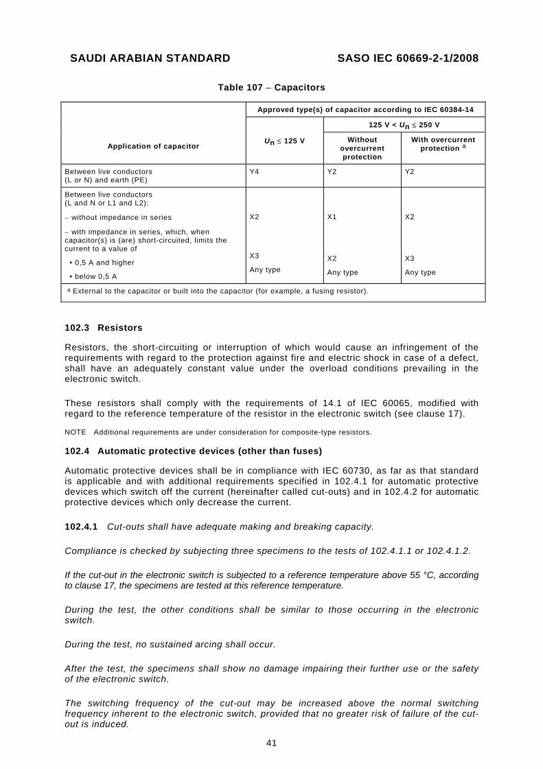
SAUDI ARABIAN STANDARD SASO IEC 60669-2-1/2008
41
Table 107 – Capacitors
Application of capacitor
Approved type(s) of capacitor according to IEC 60384-14
Un ≤ 125 V
125 V < Un ≤ 250 V
Without overcurrent protection
With overcurrent protection a
Between live conductors (L or N) and earth (PE)
Y4 Y2 Y2
Between live conductors (L and N or L1 and L2):
− without impedance in series
− with impedance in series, which, when capacitor(s) is (are) short-circuited, limits the current to a value of
• 0,5 A and higher
• below 0,5 A
X2
X3
Any type
X1
X2
Any type
X2
X3
Any type
a External to the capacitor or built into the capacitor (for example, a fusing resistor).
102.3 Resistors
Resistors, the short-circuiting or interruption of which would cause an infringement of the requirements with regard to the protection against fire and electric shock in case of a defect, shall have an adequately constant value under the overload conditions prevailing in the electronic switch.
These resistors shall comply with the requirements of 14.1 of IEC 60065, modified with regard to the reference temperature of the resistor in the electronic switch (see clause 17).
NOTE Additional requirements are under consideration for composite-type resistors.
102.4 Automatic protective devices (other than fuses)
Automatic protective devices shall be in compliance with IEC 60730, as far as that standard is applicable and with additional requirements specified in 102.4.1 for automatic protective devices which switch off the current (hereinafter called cut-outs) and in 102.4.2 for automatic protective devices which only decrease the current.
102.4.1 Cut-outs shall have adequate making and breaking capacity.
Compliance is checked by subjecting three specimens to the tests of 102.4.1.1 or 102.4.1.2.
If the cut-out in the electronic switch is subjected to a reference temperature above 55 °C, according to clause 17, the specimens are tested at this reference temperature.
During the test, the other conditions shall be similar to those occurring in the electronic switch.
During the test, no sustained arcing shall occur.
After the test, the specimens shall show no damage impairing their further use or the safety of the electronic switch.
The switching frequency of the cut-out may be increased above the normal switching frequency inherent to the electronic switch, provided that no greater risk of failure of the cut-out is induced.
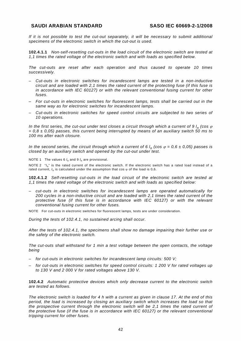
SAUDI ARABIAN STANDARD SASO IEC 60669-2-1/2008
42
If it is not possible to test the cut-out separately, it will be necessary to submit additional specimens of the electronic switch in which the cut-out is used.
102.4.1.1 Non-self-resetting cut-outs in the load circuit of the electronic switch are tested at 1,1 times the rated voltage of the electronic switch and with loads as specified below.
The cut-outs are reset after each operation and thus caused to operate 10 times successively.
– Cut-outs in electronic switches for incandescent lamps are tested in a non-inductive circuit and are loaded with 2,1 times the rated current of the protecting fuse (if this fuse is in accordance with IEC 60127) or with the relevant conventional fusing current for other fuses.
– For cut-outs in electronic switches for fluorescent lamps, tests shall be carried out in the same way as for electronic switches for incandescent lamps.
– Cut-outs in electronic switches for speed control circuits are subjected to two series of 10 operations.
In the first series, the cut-out under test closes a circuit through which a current of 9 ln (cos ϕ = 0,8 ± 0,05) passes, this current being interrupted by means of an auxiliary switch 50 ms to 100 ms after each closure.
In the second series, the circuit through which a current of 6 ln (cos ϕ = 0,6 ± 0,05) passes is closed by an auxiliary switch and opened by the cut-out under test.
NOTE 1 The values 6 ln and 9 ln are provisional.
NOTE 2 “In” is the rated current of the electronic switch. If the electronic switch has a rated load instead of a rated current, In is calculated under the assumption that cos ϕ of the load is 0,6.
102.4.1.2 Self-resetting cut-outs in the load circuit of the electronic switch are tested at 1,1 times the rated voltage of the electronic switch and with loads as specified below:
– cut-outs in electronic switches for incandescent lamps are operated automatically for 200 cycles in a non-inductive circuit and are loaded with 2,1 times the rated current of the protective fuse (if this fuse is in accordance with IEC 60127) or with the relevant conventional fusing current for other fuses.
NOTE For cut-outs in electronic switches for fluorescent lamps, tests are under consideration.
During the tests of 102.4.1, no sustained arcing shall occur.
After the tests of 102.4.1, the specimens shall show no damage impairing their further use or the safety of the electronic switch.
The cut-outs shall withstand for 1 min a test voltage between the open contacts, the voltage being
– for cut-outs in electronic switches for incandescent lamp circuits: 500 V; – for cut-outs in electronic switches for speed control circuits: 1 200 V for rated voltages up
to 130 V and 2 000 V for rated voltages above 130 V.
102.4.2 Automatic protective devices which only decrease current to the electronic switch are tested as follows.
The electronic switch is loaded for 4 h with a current as given in clause 17. At the end of this period, the load is increased by closing an auxiliary switch which increases the load so that the prospective current through the electronic switch will be 2,1 times the rated current of the protective fuse (if the fuse is in accordance with IEC 60127) or the relevant conventional tripping current for other fuses.
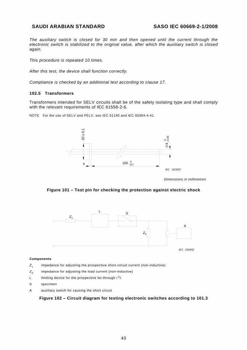
SAUDI ARABIAN STANDARD SASO IEC 60669-2-1/2008
43
The auxiliary switch is closed for 30 min and then opened until the current through the electronic switch is stabilized to the original value, after which the auxiliary switch is closed again.
This procedure is repeated 10 times.
After this test, the device shall function correctly.
Compliance is checked by an additional test according to clause 17.
102.5 Transformers
Transformers intended for SELV circuits shall be of the safety isolating type and shall comply with the relevant requirements of IEC 61558-2-6.
NOTE For the use of SELV and PELV, see IEC 61140 and IEC 60364-4-41.
100∅
4IEC 1523/02
20 ±
0,1
4 0 –0
,05
0–0,1
Dimensions in millimetres
Figure 101 – Test pin for checking the protection against electric shock
Z1
Z2
L S
A
IEC 1524/02
Components
Z1 impedance for adjusting the prospective short-circuit current (non-inductive)
Z2 impedance for adjusting the load current (non-inductive)
L limiting device for the prospective let-through I 2t
S specimen
A auxiliary switch for causing the short circuit
Figure 102 – Circuit diagram for testing electronic switches according to 101.3
SAUDI ARABIAN STANDARD SASO IEC 60669-2-1/2008
44
Annex A (normative)
Survey of specimens needed for tests
Annex A of part 1 applies.
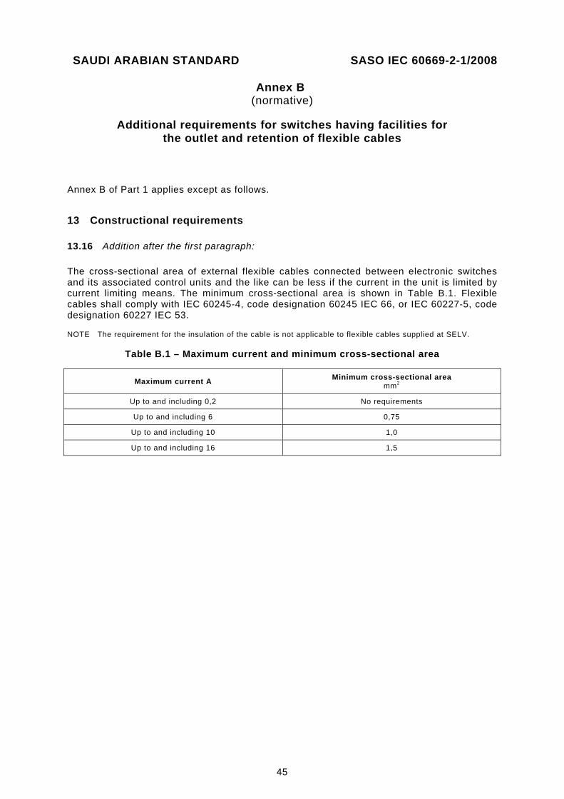
SAUDI ARABIAN STANDARD SASO IEC 60669-2-1/2008
45
Annex B (normative)
Additional requirements for switches having facilities for
the outlet and retention of flexible cables
Annex B of Part 1 applies except as follows.
13 Constructional requirements
13.16 Addition after the first paragraph:
The cross-sectional area of external flexible cables connected between electronic switches and its associated control units and the like can be less if the current in the unit is limited by current limiting means. The minimum cross-sectional area is shown in Table B.1. Flexible cables shall comply with IEC 60245-4, code designation 60245 IEC 66, or IEC 60227-5, code designation 60227 IEC 53.
NOTE The requirement for the insulation of the cable is not applicable to flexible cables supplied at SELV.
Table B.1 – Maximum current and minimum cross-sectional area
Maximum current A Minimum cross-sectional area mm2
Up to and including 0,2 No requirements
Up to and including 6 0,75
Up to and including 10 1,0
Up to and including 16 1,5
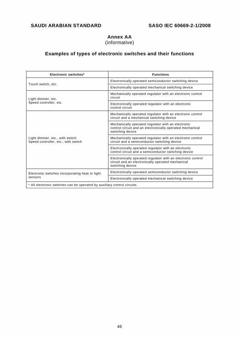
SAUDI ARABIAN STANDARD SASO IEC 60669-2-1/2008
46
Annex AA (informative)
Examples of types of electronic switches and their functions
Electronic switches* Functions
Touch switch, etc. Electronically operated semiconductor switching device
Electronically operated mechanical switching device
Light dimmer, etc. Speed controller, etc.
Mechanically operated regulator with an electronic control circuit
Electronically operated regulator with an electronic control circuit
Light dimmer, etc., with switch Speed controller, etc., with switch
Mechanically operated regulator with an electronic control circuit and a mechanical switching device
Mechanically operated regulator with an electronic control circuit and an electronically operated mechanical switching device
Mechanically operated regulator with an electronic control circuit and a semiconductor switching device
Electronically operated regulator with an electronic control circuit and a semiconductor switching device
Electronically operated regulator with an electronic control circuit and an electronically operated mechanical switching device
Electronic switches incorporating heat or light sensors
Electronically operated semiconductor switching device
Electronically operated mechanical switching device
* All electronic switches can be operated by auxiliary control circuits.
SAUDI ARABIAN STANDARD SASO IEC 60669-2-1/2008
47
Bibliography
IEC 60050-601:1985, International Electrotechnical Vocabulary – Chapter 601: Generation, transmission and distribution of electricity – General
IEC 60364-4-41, Low-voltage electrical installations – Part 4-41: Protection for safety – Protection against electric shock
IEC 61058-1, Switches for appliances – Part 1: General requirements
IEC 61140, Protection against electric shock – Common aspects for installation and equipment
___________


![DRAFT MALAYSIAN STANDARD - · PDF file4 Principles and practical application of the MS IEC 60664 series for insulation dimensioning of LV equipment ... [IEC 60664-1:2007, 3.20]](https://img.pdfslide.us/doc/110x75/5aa5ab9c7f8b9a2f048db7d6/draft-malaysian-standard-4-principles-and-practical-application-of-the-ms-iec.jpg)