Embed Size (px)
Citation preview
Engineering Standard
SAES-P-103 20 October 2008 UPS and DC Systems
UPS, DC Systems and Power Electronics Standards Committee Members Jofaish, Mohammed Abdullah, Chairman Masoud, Khalid Hasan, Vice Chairman Khouri, Edgar Lawandos Abboud, Brett Jeffrey Bishop, Tony C. Bamardouf, Lutfi Hussain Hamaqi, Saeed Mohammad Qahtani, Mohammad Marai Otaish, Naji Saleh Qahtani, Naser Hadi Dubaikel, Faisal Abdulhameed
Saudi Aramco DeskTop Standards Table of Contents 1 Scope............................................................. 2 2 Conflicts and Deviations................................. 3 3 References..................................................... 3 4 Systems' Descriptions.................................... 6 5 Battery Selection, Sizing and Load Determination......................... 6 6 Battery Installations...................................... 13 7 Battery Chargers/Rectifiers.......................... 22 8 Uninterruptible Power Supply (UPS) Systems..................................... 24 9 Photovoltaic (Solar) Systems....................... 30 10 Battery Tests and Records........................... 33 Attachment 1 – Battery Room Ventilation Calculations................................................. 34 Attachment 2 – Example of UPS Sizing............. 35 Attachment 3 – Example of Solar Photovoltaic System Sizing Calculations..... 36
Attachment 4 – Online Double Conversion UPS Configuration........................................ 38
Previous Issue: 2 June 2008 Next Planned Update: 1 January 2011 Revised paragraphs are indicated in the right margin Page 1 of 42 Primary contact: Masoud, Khalid Hasan on 966-3-8760292
Copyright©Saudi Aramco 2005. All rights reserved.
Document Responsibility: UPS, DC Systems and Power Electronics SAES-P-103 Issue Date: 20 October 2008 Next Planned Update: 1 January 2011 UPS and DC Systems
Page 2 of 42
Table of Contents (Cont'd) 1 Scope............................................................. 2 2 Conflicts and Deviations................................. 2 3 References..................................................... 2 4 Systems' Descriptions.................................... 5 5 Battery Selection, Sizing and Load Determination......................... 6 6 Battery Installations...................................... 12 7 Battery Chargers/Rectifiers.......................... 21 8 Uninterruptible Power Supply (UPS) Systems..................................... 23 9 Photovoltaic (Solar) Systems....................... 29 10 Battery Tests and Records........................... 32 Attachment 1 – Battery Room Ventilation Calculations................................................. 33 Attachment 2 – Example of UPS Sizing............. 34 Attachment 3 – Example of Solar Photovoltaic System Sizing Calculations..... 35
Attachment 4 – Online Double Conversion UPS Configuration........................................ 37
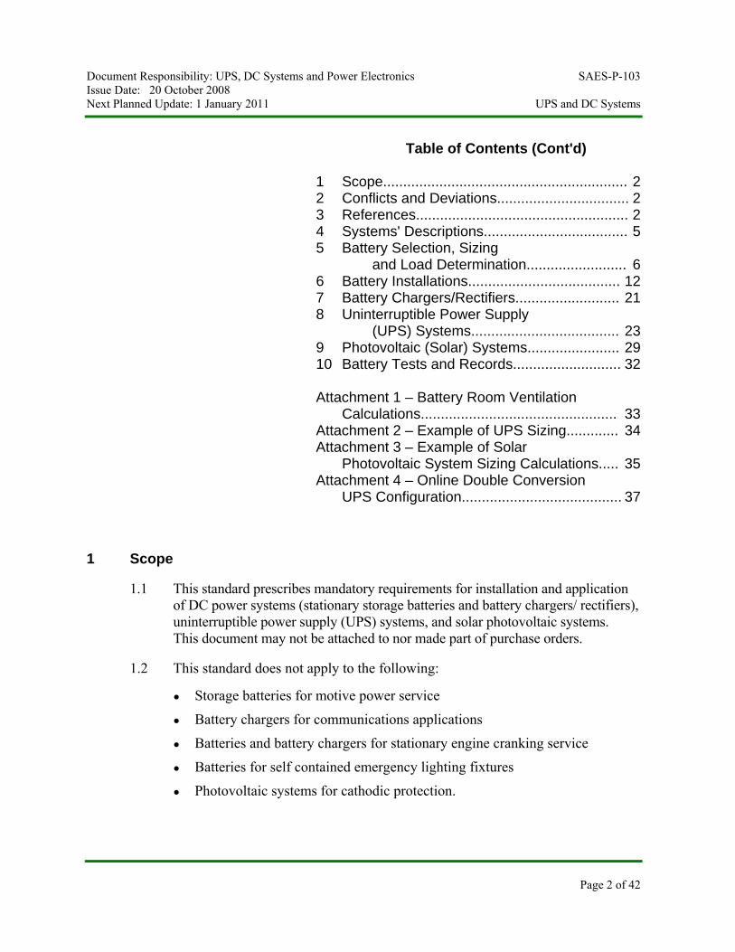
1 Scope
1.1 This standard prescribes mandatory requirements for installation and application of DC power systems (stationary storage batteries and battery chargers/ rectifiers), uninterruptible power supply (UPS) systems, and solar photovoltaic systems. This document may not be attached to nor made part of purchase orders.
1.2 This standard does not apply to the following:
● Storage batteries for motive power service
● Battery chargers for communications applications
● Batteries and battery chargers for stationary engine cranking service
● Batteries for self contained emergency lighting fixtures
● Photovoltaic systems for cathodic protection.
Document Responsibility: UPS, DC Systems and Power Electronics SAES-P-103 Issue Date: 20 October 2008 Next Planned Update: 1 January 2011 UPS and DC Systems
Page 3 of 42
2 Conflicts and Deviations
2.1 Any conflicts between this Standard and other Mandatory Saudi Aramco Engineering Requirements (MSAERs*) or referenced industry standards shall be identified to the Company or Buyer Representative who will request the Manager, Consulting Services Department of Saudi Aramco, Dhahran to resolve the conflict. This standard shall take precedence over any other project documents.
* Examples of MSAERs are Saudi Aramco Materials System Specifications (SAMSSs), Engineering Standards (SAESs) and Standard Drawings (SASDs).
2.2 Direct all requests to deviate from this standard in writing to the company or buyer representative, who shall follow internal company procedure SAEP-302 and forward such requests to the Manager, Consulting Services Department of Saudi Aramco, Dhahran.
2.3 The designation "Commentary" is used to label a sub-paragraph that contains comments that are explanatory or advisory. These comments are not mandatory, except to the extent that they explain mandatory requirements contained in this SAES.
3 References
All referenced standards, specifications, codes, forms, drawings and similar material shall be the latest issue (including all revisions, addenda and supplements) unless stated otherwise.
3.1 Saudi Aramco References
Saudi Aramco Engineering Procedures
SAEP-302 Instructions for Obtaining a Waiver of a Mandatory Saudi Aramco Engineering Requirement
SAEP-350 Regular Maintenance and Testing for Industrial Stationary Batteries
Saudi Aramco Engineering Standards
SAES-B-069 Emergency Eyewash and Showers
SAES-J-902 Electrical Systems for Instrumentation
SAES-P-100 Basic Power System Design Criteria
SAES-P-104 Wiring Methods and Materials
SAES-P-111 Grounding
Document Responsibility: UPS, DC Systems and Power Electronics SAES-P-103 Issue Date: 20 October 2008 Next Planned Update: 1 January 2011 UPS and DC Systems
Page 4 of 42
SAES-P-123 Lighting
SAES-S-060 Saudi Aramco Plumbing Code
Saudi Aramco Materials System Specifications
16-SAMSS-518 Low Voltage Panelboards
16-SAMSS-519 Indoor Switchboard – Low Voltage
16-SAMSS-521 Indoor Automatic Transfer Switch – Low Voltage
17-SAMSS-511 Stationary Storage Batteries
17-SAMSS-514 Battery Rectifier/charger
17-SAMSS-516 Uninterruptible Power Supply (UPS) Systems
Saudi Aramco Supply Chain Management (SCM) Manual
CU 22.03 Processing and Handling of Hazardous Material
3.2 Industry Codes and Standards
Institute of Electrical and Electronics Engineers, Inc.
IEEE 450 IEEE Recommended Practice for Maintenance Testing and Replacement of Vented Lead-Acid Batteries for Stationary Applications
IEEE 484 IEEE Recommended Practice for Installation Design and Installation of Vented Lead-Acid Batteries for Stationary Applications
IEEE 485 IEEE Recommended Practice for Sizing Lead-Acid Batteries for Stationary Applications
IEEE 1013 IEEE Recommended Practice for Sizing Lead-Acid Batteries for Photovoltaic (PV) Systems
IEEE 1106 Recommended Practice for Installation, Maintenance, Testing, and Replacement of Vented Nickel-Cadmium Batteries for Stationary Applications
IEEE 1115 Recommended Practice for Sizing Nickel-Cadmium Batteries for Stationary Applications
IEEE 1184 IEEE Guide for the Selection and Sizing of Batteries for Uninterruptible Power Systems
IEEE 1188 IEEE Recommended Practice for Maintenance Testing and Replacement of Valve-Regulated
Document Responsibility: UPS, DC Systems and Power Electronics SAES-P-103 Issue Date: 20 October 2008 Next Planned Update: 1 January 2011 UPS and DC Systems
Page 5 of 42
Lead-Acid (VRLA) Batteries for Stationary Applications
National Fire Protections Association
NFPA 10 Fire Protection System for Battery Rooms
NFPA 70 National Electrical Code
NFPA 75 Protection of Information Technology Equipment
NFPA 101 Life Safety Code
NFPA 496 Purged and Pressurized Enclosures for Electrical Equipment in Hazardous (Classified) Locations
Underwriters Laboratories, Inc.
UL 94 Tests for Flammability of Plastic Materials for Parts in Devices and Appliances: Vertical Burning Tests for Classifying Materials 94V-0, 94V-1, or 94V-2
UL 924 Emergency Lighting and Power Equipment
UL 1778 Uninterruptiple Power Systems
International Electrotechnical Commission
IEC 60726 Dry Type Power Transformers
IEC 60146 Semiconductor Converters - General Requirements and Line Commutated Converters: Parts 1 through 6
IEC 60478 Stabilized Power Supplies, D.C. Output: Parts 1 through 5
IEC 60529 Degree of Protection Provided by Enclosures (IP Code)
IEC 62040-2 UPS – Electromagnetic Compatibility Requirements
IEC 60623 Vented Nickel-Cadmium Prismatic Rechargeable Single cells
IEC 60707 Methods of Test for the Determination of the Flammability of Solid Electrical Insulating Materials When Exposed to an Igniting Source
Document Responsibility: UPS, DC Systems and Power Electronics SAES-P-103 Issue Date: 20 October 2008 Next Planned Update: 1 January 2011 UPS and DC Systems
Page 6 of 42
IEC 60896-11 Stationary Lead-Acid Batteries - General Requirements and Methods of Test, Part 1: Vented Types
IEC 60896-21 Stationary Lead-Acid Batteries - General Requirements and Methods of Test, Part 2: Valve
IEC 61427 Batteries for Photovoltaics
IEC 62259 Gas recombination Ni-Cd Battery
European Standard
EN 50091-2, Class A Uninterruptible Power Systems – Electromagnetic Compatibility Requirements
BS EN 50178 Electronic Equipment for Use in Power Installations
4 Systems' Descriptions
4.1 DC Power System shall consist of, but not limited to batteries, battery circuit breaker, battery rectifier/charger, DC/DC converter (if requested), output distribution panelboards (if requested) and management system.
4.2 Uninterruptible Power Supply (UPS) System shall consist of, but not limited to batteries, battery circuit breaker, battery rectifier/charger, inverter, static transfer switch, manual bypass line, bypass shielded isolation transformer, output distribution panelboards and management system.
4.3 Solar Photovoltaic (PV) Power System shall consist of, but not limited to batteries, photovoltaic panels, charge regulator and output distribution panelboards. If AC output is required, DC/AC converter shall be included.
5 Battery Selection, Sizing and Load Determination
5.1 General
Batteries shall comply with 17-SAMSS-511.
5.2 Battery selection shall be made according to the following guidelines. Other plate designs and alloys would be given consideration after their performance characteristics have been reviewed and approved by the Consulting Services Department for the intended application.
5.2.1 Lead-calcium or lead low antimony pasted flat plate batteries are generally most suitable for standby float service applications in an
Document Responsibility: UPS, DC Systems and Power Electronics SAES-P-103 Issue Date: 20 October 2008 Next Planned Update: 1 January 2011 UPS and DC Systems
Page 7 of 42
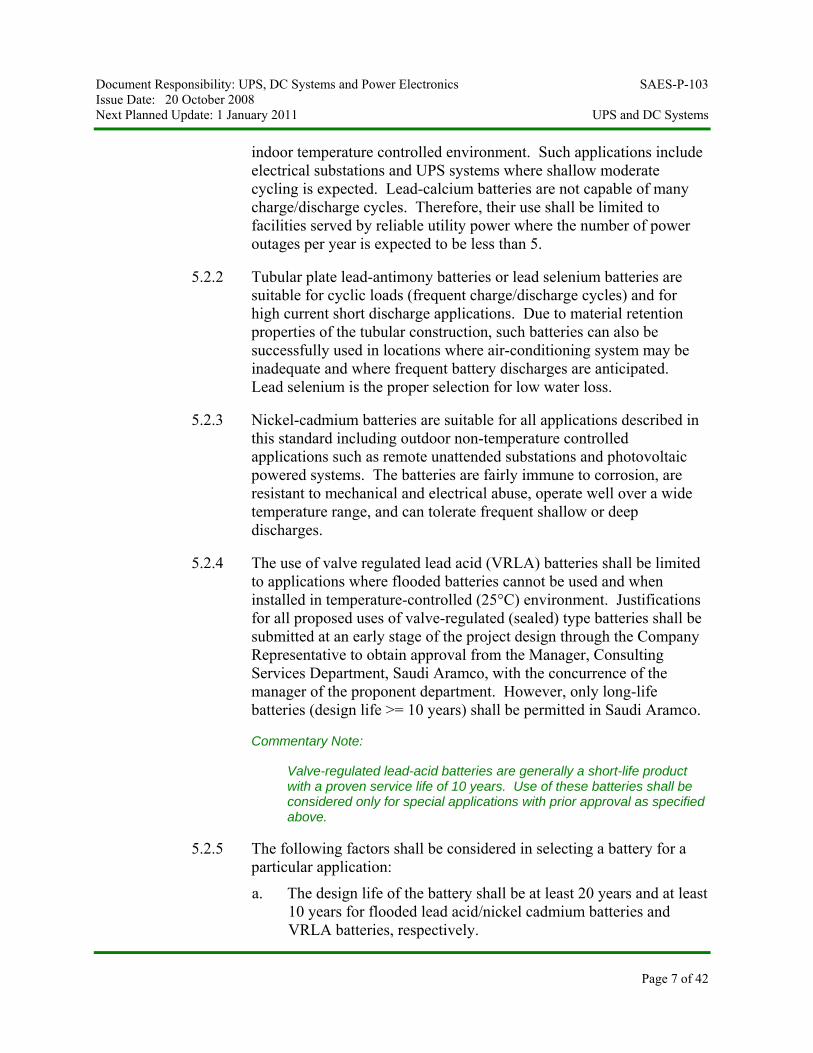
indoor temperature controlled environment. Such applications include electrical substations and UPS systems where shallow moderate cycling is expected. Lead-calcium batteries are not capable of many charge/discharge cycles. Therefore, their use shall be limited to facilities served by reliable utility power where the number of power outages per year is expected to be less than 5.
5.2.2 Tubular plate lead-antimony batteries or lead selenium batteries are suitable for cyclic loads (frequent charge/discharge cycles) and for high current short discharge applications. Due to material retention properties of the tubular construction, such batteries can also be successfully used in locations where air-conditioning system may be inadequate and where frequent battery discharges are anticipated. Lead selenium is the proper selection for low water loss.
5.2.3 Nickel-cadmium batteries are suitable for all applications described in this standard including outdoor non-temperature controlled applications such as remote unattended substations and photovoltaic powered systems. The batteries are fairly immune to corrosion, are resistant to mechanical and electrical abuse, operate well over a wide temperature range, and can tolerate frequent shallow or deep discharges.
5.2.4 The use of valve regulated lead acid (VRLA) batteries shall be limited to applications where flooded batteries cannot be used and when installed in temperature-controlled (25°C) environment. Justifications for all proposed uses of valve-regulated (sealed) type batteries shall be submitted at an early stage of the project design through the Company Representative to obtain approval from the Manager, Consulting Services Department, Saudi Aramco, with the concurrence of the manager of the proponent department. However, only long-life batteries (design life >= 10 years) shall be permitted in Saudi Aramco.
Commentary Note:
Valve-regulated lead-acid batteries are generally a short-life product with a proven service life of 10 years. Use of these batteries shall be considered only for special applications with prior approval as specified above.
5.2.5 The following factors shall be considered in selecting a battery for a particular application:
a. The design life of the battery shall be at least 20 years and at least 10 years for flooded lead acid/nickel cadmium batteries and VRLA batteries, respectively.
Document Responsibility: UPS, DC Systems and Power Electronics SAES-P-103 Issue Date: 20 October 2008 Next Planned Update: 1 January 2011 UPS and DC Systems
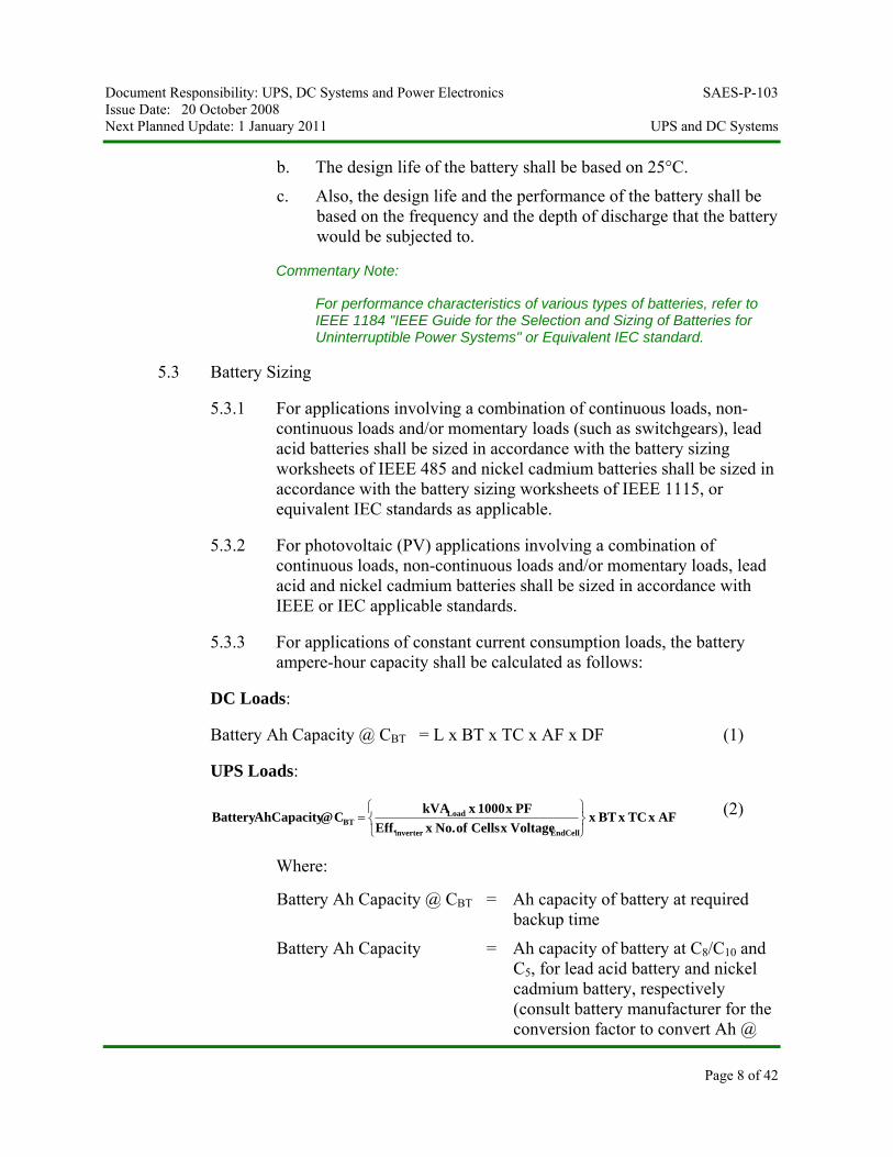
b. The design life of the battery shall be based on 25°C.
c. Also, the design life and the performance of the battery shall be based on the frequency and the depth of discharge that the battery would be subjected to.
Commentary Note:
For performance characteristics of various types of batteries, refer to IEEE 1184 "IEEE Guide for the Selection and Sizing of Batteries for Uninterruptible Power Systems" or Equivalent IEC standard.
5.3 Battery Sizing
5.3.1 For applications involving a combination of continuous loads, non-continuous loads and/or momentary loads (such as switchgears), lead acid batteries shall be sized in accordance with the battery sizing worksheets of IEEE 485 and nickel cadmium batteries shall be sized in accordance with the battery sizing worksheets of IEEE 1115, or equivalent IEC standards as applicable.
5.3.2 For photovoltaic (PV) applications involving a combination of continuous loads, non-continuous loads and/or momentary loads, lead acid and nickel cadmium batteries shall be sized in accordance with IEEE or IEC applicable standards.
5.3.3 For applications of constant current consumption loads, the battery ampere-hour capacity shall be calculated as follows:
DC Loads:
Battery Ah Capacity @ CBT = L x BT x TC x AF x DF (1)
UPS Loads:
AFxTCxBTxVoltagexCellsofNo.xEff.PFx1000xkVAC @ Capacity AhBattery
EndCellnverter
LoadBT
⎭⎬⎫
⎩⎨⎧
=i
(2)
Where:
Battery Ah Capacity @ CBT = Ah capacity of battery at required backup time
Battery Ah Capacity = Ah capacity of battery at C8/C10 and C5, for lead acid battery and nickel cadmium battery, respectively (consult battery manufacturer for the conversion factor to convert Ah @
Page 8 of 42
Document Responsibility: UPS, DC Systems and Power Electronics SAES-P-103 Issue Date: 20 October 2008 Next Planned Update: 1 January 2011 UPS and DC Systems
Page 9 of 42
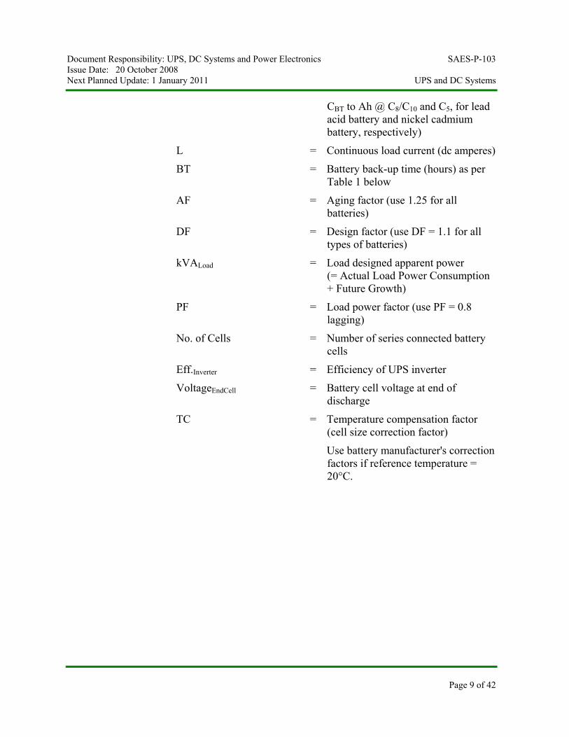
CBT to Ah @ C8/C10 and C5, for lead acid battery and nickel cadmium battery, respectively)
L = Continuous load current (dc amperes)
BT = Battery back-up time (hours) as per Table 1 below
AF = Aging factor (use 1.25 for all batteries)
DF = Design factor (use DF = 1.1 for all types of batteries)
kVALoad = Load designed apparent power (= Actual Load Power Consumption + Future Growth)
PF = Load power factor (use PF = 0.8 lagging)
No. of Cells = Number of series connected battery cells
Eff.Inverter = Efficiency of UPS inverter
VoltageEndCell = Battery cell voltage at end of discharge
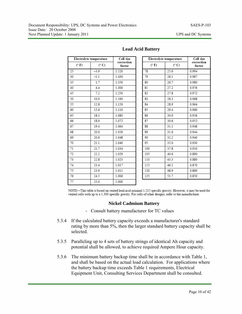
TC = Temperature compensation factor (cell size correction factor)
Use battery manufacturer's correction factors if reference temperature = 20°C.
Document Responsibility: UPS, DC Systems and Power Electronics SAES-P-103 Issue Date: 20 October 2008 Next Planned Update: 1 January 2011 UPS and DC Systems
Lead Acid Battery
Nickel Cadmium Battery - Consult battery manufacturer for TC values
5.3.4 If the calculated battery capacity exceeds a manufacturer's standard rating by more than 5%, then the larger standard battery capacity shall be selected.
5.3.5 Paralleling up to 4 sets of battery strings of identical Ah capacity and potential shall be allowed, to achieve required Ampere Hour capacity.
5.3.6 The minimum battery backup time shall be in accordance with Table 1, and shall be based on the actual load calculation. For applications where the battery backup time exceeds Table 1 requirements, Electrical Equipment Unit, Consulting Services Department shall be consulted.
Page 10 of 42
Document Responsibility: UPS, DC Systems and Power Electronics SAES-P-103 Issue Date: 20 October 2008 Next Planned Update: 1 January 2011 UPS and DC Systems
Page 11 of 42
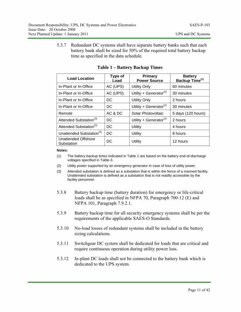
5.3.7 Redundant DC systems shall have separate battery banks such that each battery bank shall be sized for 50% of the required total battery backup time as specified in the data schedule.
Table 1 – Battery Backup Times
Load Location Type of Load
Primary Power Source
Battery Backup Time(1)
In-Plant or In-Office AC (UPS) Utility Only 60 minutes
In-Plant or In-Office AC (UPS) Utility + Generator(2) 30 minutes
In-Plant or In-Office DC Utility Only 2 hours
In-Plant or In-Office DC Utility + Generator(2) 30 minutes
Remote AC & DC Solar Photovoltaic 5 days (120 hours)
Attended Substation(3) DC Utility + Generator(2) 2 hours
Attended Substation(3) DC Utility 4 hours
Unattended Substation(3) DC Utility 8 hours Unattended Offshore Substation DC Utility 12 hours
Notes: (1) The battery backup times indicated in Table 1 are based on the battery end-of-discharge
voltages specified in Table-3. (2) Utility power supported by an emergency generator in case of loss of utility power. (3) Attended substation is defined as a substation that is within the fence of a manned facility.
Unattended substation is defined as a substation that is not readily accessible by the facility personnel.
5.3.8 Battery backup time (battery duration) for emergency or life-critical loads shall be as specified in NFPA 70, Paragraph 700-12 (E) and NFPA 101, Paragraph 7.9.2.1.
5.3.9 Battery backup time for all security emergency systems shall be per the requirements of the applicable SAES-O Standards.
5.3.10 No-load losses of redundant systems shall be included in the battery sizing calculations.
5.3.11 Switchgear DC system shall be dedicated for loads that are critical and require continuous operation during utility power loss.
5.3.12 In-plant DC loads shall not be connected to the battery bank which is dedicated to the UPS system.
Document Responsibility: UPS, DC Systems and Power Electronics SAES-P-103 Issue Date: 20 October 2008 Next Planned Update: 1 January 2011 UPS and DC Systems
Page 12 of 42
Commentary Note:
Connecting DC loads to the UPS battery affects the reliability of the UPS and should not be practiced.
5.3.13 Substation battery systems shall be dedicated to connected DC load and shall not be part of a plant UPS or other DC system.
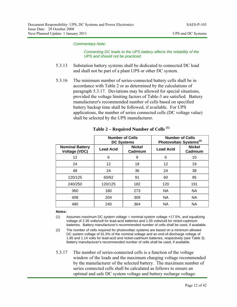
5.3.16 The minimum number of series-connected battery cells shall be in accordance with Table 2 or as determined by the calculations of paragraph 5.3.17. Deviations may be allowed for special situations, provided the voltage limiting factors of Table-3 are satisfied. Battery manufacturer's recommended number of cells based on specified battery backup time shall be followed, if available. For UPS applications, the number of series connected cells (DC voltage value) shall be selected by the UPS manufacturer.
Table 2 – Required Number of Cells (1)
Number of Cells DC Systems
Number of Cells Photovoltaic Systems(2)
Nominal Battery Voltage (VDC) Lead Acid Nickel
Cadmium Lead Acid Nickel Cadmium
12 6 9 6 10
24 12 18 12 19
48 24 36 24 38
120/125 60/62 91 60 95
240/250 120/125 182 120 191
360 180 273 NA NA
408 204 309 NA NA
480 240 364 NA NA
Notes: (1) Assumes maximum DC system voltage = nominal system voltage +17.5%, and equalizing
voltage of 2.35 volts/cell for lead-acid batteries and 1.55 volts/cell for nickel-cadmium batteries. Battery manufacturer's recommended number of cells shall be used, if available.
(2) The number of cells required for photovoltaic systems are based on a minimum allowed DC system voltage of 91.5% of the nominal voltage and an end-of-discharge voltage of 1.85 and 1.14 volts for lead-acid and nickel-cadmium batteries, respectively (see Table 3). Battery manufacturer's recommended number of cells shall be used, if available.
5.3.17 The number of series-connected cells is a function of the voltage window of the loads and the maximum charging voltage recommended by the manufacturer of the selected battery. The maximum number of series connected cells shall be calculated as follows to ensure an optimal and safe DC system voltage and battery recharge voltage:
Document Responsibility: UPS, DC Systems and Power Electronics SAES-P-103 Issue Date: 20 October 2008 Next Planned Update: 1 January 2011 UPS and DC Systems
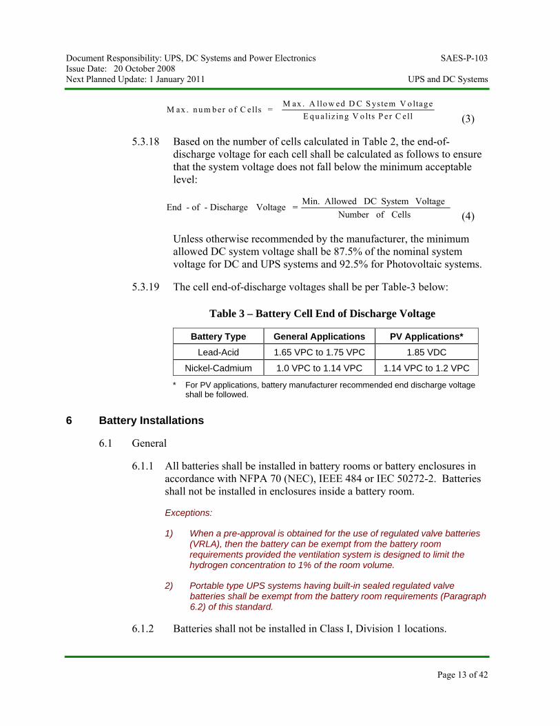
M ax . n u m b er o f C ells = M ax . A llo w ed D C S ystem V o ltage
E q u aliz in g V o lts P er C ell (3)
5.3.18 Based on the number of cells calculated in Table 2, the end-of-discharge voltage for each cell shall be calculated as follows to ensure that the system voltage does not fall below the minimum acceptable level:
Cells ofNumber Voltage System DC Allowed Min. = Voltage Discharge-of-End
(4)
Unless otherwise recommended by the manufacturer, the minimum allowed DC system voltage shall be 87.5% of the nominal system voltage for DC and UPS systems and 92.5% for Photovoltaic systems.
5.3.19 The cell end-of-discharge voltages shall be per Table-3 below:
Table 3 – Battery Cell End of Discharge Voltage
Battery Type General Applications PV Applications* Lead-Acid 1.65 VPC to 1.75 VPC 1.85 VDC
Nickel-Cadmium 1.0 VPC to 1.14 VPC 1.14 VPC to 1.2 VPC
* For PV applications, battery manufacturer recommended end discharge voltage shall be followed.
6 Battery Installations
6.1 General
6.1.1 All batteries shall be installed in battery rooms or battery enclosures in accordance with NFPA 70 (NEC), IEEE 484 or IEC 50272-2. Batteries shall not be installed in enclosures inside a battery room.
Exceptions:
1) When a pre-approval is obtained for the use of regulated valve batteries (VRLA), then the battery can be exempt from the battery room requirements provided the ventilation system is designed to limit the hydrogen concentration to 1% of the room volume.
2) Portable type UPS systems having built-in sealed regulated valve batteries shall be exempt from the battery room requirements (Paragraph 6.2) of this standard.
6.1.2 Batteries shall not be installed in Class I, Division 1 locations.
Page 13 of 42
Document Responsibility: UPS, DC Systems and Power Electronics SAES-P-103 Issue Date: 20 October 2008 Next Planned Update: 1 January 2011 UPS and DC Systems
Page 14 of 42
6.1.3 Batteries installed in Class I, Division 2, locations shall be in a building or enclosure made safe by pressurized air from a safe source. Loss of pressurization shall be monitored in accordance with NFPA 496.
6.1.4 Working space of at least 1 meter shall be provided in front of each battery rack or enclosure.
6.1.5 Batteries shall be supplied with covers for all inter-cell connecters and terminals or insulated copper busbars to enhance safety.
6.2 Battery Rooms
6.2.1 Battery room walls and floor shall be made of concrete construction.
6.2.2 Manned workstations shall not be located in battery rooms.
6.2.3 Battery rooms shall be provided with enclosed and gasketed (i.e., vapor tight) corrosion resistant lighting fixtures as specified in SAES-P-123. Battery room lighting shall be installed to provide a minimum level of illumination of 30-ft candles (300 lux). Emergency lighting with compatible illumination level shall be installed to operate in the event of loss of mains power supply.
6.2.4 Battery room doors shall open outward, away from the room, to the outside of the building, and be fitted with door closers and anti-panic (quick-release, quick-opening) hardware. No hasp, padlock, or other device shall be installed which will hinder operation of the emergency door opening devices.
6.2.5 Doors between battery rooms and other rooms shall not be permitted.
6.2.6 Portable water facilities shall be provided for rinsing spilled electrolyte in the battery room. Raw water shall not be used (as it is rich of minerals and dissolved solids that may react with the electrolyte). The amount of water supply shall be determined based on a risk assessment of the extreme scenario where the largest battery or electrolyte container gets spilled.
6.2.7 Provisions for neutralizing the battery electrolyte (acid or alkali) and caustic spillage shall be included in the battery room design.
6.2.8 Floor drains shall comply with SAES-S-060.
Exception:
Sealed valve-regulated batteries do not require floor drains.
Document Responsibility: UPS, DC Systems and Power Electronics SAES-P-103 Issue Date: 20 October 2008 Next Planned Update: 1 January 2011 UPS and DC Systems
Page 15 of 42
6.2.9 Emergency eyewash facilities shall be provided as required by SAES-B-069.
Exception:
Sealed valve-regulated batteries do not require eyewash facilities.
6.2.10 Battery room floor shall be covered with an electrolyte (acid or alkali) resistant, durable, antistatic and slip-resistant surface overall, to a height 100 mm on each wall. Where batteries are mounted against a wall, the wall behind and at each end of the battery shall be coated to a distance of 500 mm around the battery with an electrolyte resistant paint or tiles.
6.2.11 A dry chemical fire extinguisher shall be installed on the outside of the battery room.
6.2.12 Cabinets or racks shall be provided in the battery room for storing maintenance tools and safety equipment. These cabinets and racks shall be acid or alkaline resistant as applicable.
6.3 Ventilation of Battery Room
6.3.1 Battery rooms shall be vented to the outside air by forced ventilation to prevent accumulation of hydrogen and to maintain design temperature. The ventilation system is determined such that the hydrogen concentration shall be limited to less than 1% of the total air volume of the battery room.
Commentary Notes:
a. The maximum hydrogen evolution rate for all kinds of flooded batteries is 0.000457 m³/hour (0.016 ft³/hour), per charging ampere, per cell, at 25°C, at standard pressure. The worst condition (the maximum hydrogen evolution) occurs when current is forced into a fully charged battery (overcharge).
b. To determine the rate of hydrogen evolution for valve-regulated batteries, the battery manufacturer shall be consulted.
6.3.2 Interlock between the High-Rate Charge and Ventilation Operation
a) An interlock between the air-handling unit and the high-rate charging switch shall be provided, such that failure of the air-handling unit shall cause the high-rate charging of batteries to stop.
b) The ventilation system shall be 100% redundant. Only direct driven exhaust fans shall be used. An interlock with the
Document Responsibility: UPS, DC Systems and Power Electronics SAES-P-103 Issue Date: 20 October 2008 Next Planned Update: 1 January 2011 UPS and DC Systems
Page 16 of 42
ventilation system shall be provided to stop the high-rate battery charging if the exhaust fan stops.
Commentary Note:
There is difficulty in detection of a loose and/or broken belt of a belt driven exhaust fan.
c) An alternative to interlocking with either air-handling unit or exhaust fans is to interlock the high-rate battery charging system with either an air-flow or air-pressure measuring device, such that ventilation insufficient to the 1% hydrogen limit will cause the high-rate charge to stop.
Exception:
This eliminates the need for explosion proof equipment in battery room.
d) Audible and visual alarm shall be installed outside the battery room entrance to annunciate a failure in ventilation for immediate action.
6.3.3 Ventilation requirements, at the design room temperature, shall be calculated in accordance with Attachment 1. The minimum ventilation shall be one complete air change every 3 hours.
6.3.4 A battery area that meets the above ventilation requirements and the high-rate charge interlock shall be considered non-hazardous. Therefore special electrical equipment enclosures to prevent fire or explosions shall not be required.
6.3.5 Equipment with arcing contacts shall be located in such a manner as to avoid those areas where hydrogen pockets could form. Electrical equipment shall not be located directly above the batteries and, as a rule, shall have a minimum horizontal separation of 1.5 meters from the nearest cell.
Commentary Note:
It is recommended that all electrical devices with arching contacts (such as lighting switches) be installed outside the battery room as practically possible.
6.3.6 Temperature in a room that contains batteries shall not exceed 25°C.
Commentary Note:
If battery operating temperature increases by 10°C above the 25°C
Document Responsibility: UPS, DC Systems and Power Electronics SAES-P-103 Issue Date: 20 October 2008 Next Planned Update: 1 January 2011 UPS and DC Systems
Page 17 of 42
reference, battery design life will be reduced by 50% and 20% for lead acid and nickel cadmium batteries, respectively.
6.3.7 Return air-conditioning ducts from battery rooms shall be prohibited.
6.3.8 False ceiling shall not be permitted in battery rooms and ceiling shall be finished to avoid trapped pockets of hydrogen.
6.3.9 Lighting fixtures shall be installed at least 300 mm below the finished ceiling so that adequate free air space is allowed for hydrogen to disperse past the fixture.
6.3.10 Inlets of air-conditioning shall be no higher than the top of the battery cell and the outlets (exhaust) at the highest level in the room. Air inlets and outlets shall be located in such a manner to provide effective cross ventilation over the batteries.
6.3.11 If batteries are installed in a sealed passively cooled shelter, they shall be located in a separate compartment with a dedicated entrance. All battery cell vents shall be tubed so that hydrogen gas is vented outside the battery compartment.
6.4 Battery Racks
6.4.1 Battery racks shall be constructed in accordance with 17-SAMSS-511.
6.4.2 Battery racks installations shall meet NEC bonding and grounding requirements. Battery racks shall be bonded at both end points to a local supplementary grounding electrode per NEC 250 or EN 50178. Install lug and cable on the steel rack and tighten to ensure ohmmeter reading between each component and a common point on rack frame indicated continuity for proper grounding.
6.4.3 Stationary batteries shall be installed on open battery racks within a battery room to facilitate proper cooling, routine inspection, and maintenance.
6.4.4 Either covers for all inter-cell connecters and battery terminals or insulated copper busbars shall be supplied as part of the battery to enhance safety.
6.5 Battery Enclosures
For outdoor installations and some special indoor applications, batteries may be installed in an enclosure. Battery enclosures shall be in accordance with the following requirements:
Document Responsibility: UPS, DC Systems and Power Electronics SAES-P-103 Issue Date: 20 October 2008 Next Planned Update: 1 January 2011 UPS and DC Systems
Page 18 of 42
a. The enclosure design shall include a removable lid, secured by quick- release latches, type 316L stainless steel or equivalent. Hinged enclosures shall be designed to open at least 120 degrees to facilitate proper maintenance access.
b. The enclosure base shall be provided with cell supports designed to raise the cells a minimum of 5 cm above the enclosure floor.
c. For indoor use, the battery enclosures and cell supports shall be made of fiberglass reinforced material or steel, with provisions for anchoring to the floor and grounding. The ventilation requirements of paragraph 6.3 shall be complied with.
d. Valve regulated (sealed) lead acid (VRLA) batteries shall be mounted in ventilated indoors enclosures unless installed inside a dedicated battery room, where battery racks are sufficient. VRLA batteries shall not be used for outdoors applications.
e. For outdoor use, the battery enclosures shall be made of fiberglass-reinforced material.
Commentary Note:
Double-walled, insulated and passively cooled enclosures are recommended.
f. Battery enclosures for outdoor use shall be completely weatherproof, dust-tight, and rain-tight. The gasket shall be one-piece, heavy-duty black neoprene or buna nitrile rubber, mechanically attached to the enclosure lip and in continuous contact with the enclosure lid. Minimum protection Class for outdoors mounting shall be NEMA 250 Type 4 (or IEC 60529 IP65). But for offshore outdoors applications, corrosion resistance enclosure NEMA 250 Type 4X (or IEC 60529 IP65) shall be required.
g. The fiberglass material shall meet the flammability rating of UL 94 type V-0.
h. Steel enclosures and grounding lugs shall be coated with an acid-resistant or alkali-resistant (as applicable), chip and scratch resistant, baked powder epoxy or propylene.
i. All hardware shall be 316L stainless steel or equivalent.
j. The enclosure shall have an adequate number of drain openings at the bottom and a minimum of two ventilation openings at the top. The ventilation openings shall be fitted with breather-type plugs to release hydrogen gas without allowing sand/dust to enter the enclosure.
k. A minimum clearance of 15 cm shall be maintained above each cell to allow proper air circulation. A minimum clearance above the cells (when
Document Responsibility: UPS, DC Systems and Power Electronics SAES-P-103 Issue Date: 20 October 2008 Next Planned Update: 1 January 2011 UPS and DC Systems
Page 19 of 42
the enclosure lid is open) shall be 30 cm to permit filling, testing, and replacement of cells. Adequate clearance shall also be maintained in between cells. The minimum air space between cells and between cells and external walls of the enclosure shall be 1 cm.
l. Enclosures with front access only shall have no more than 2 rows of stepped cells. Enclosures with access from the front and back sides may have a maximum of 4 rows of stepped cells. In the stepped cell arrangement, cells shall be positioned in such a way that the electrolyte levels markings (both minimum and maximum) can be easily seen.
6.6 Electrical Requirements
6.6.1 Battery cables shall be sized for a total voltage drop of less than 3%.
6.6.2 Positive and negative battery cables shall be run in the same conduit to prevent inductive heating.
6.6.3 The positive and negative buses of batteries shall be isolated from earth ground.
Exception:
Instrumentation loads shall comply with SAES-J-902.
6.6.4 Each battery-based system shall be equipped with properly sized two-pole fused disconnect switch or circuit breaker with an undervoltage release feature to prevent battery discharge beyond the battery's end-of-discharge voltage. The undervoltage device shall disconnect the battery from the load when the battery voltage drops to the end-of-discharge voltage specified in Table-3.
Commentary Note:
The battery manufacturer can be consulted to the sizing of the battery short-circuit protection. Normally, Battery Short-circuit Current = Battery Voltage/Battery Internal resistance. If manufacturer data is not available, the protective fault level at the battery terminals can be considered to be twenty times the nominal battery capacity (AH).
6.7 Battery Alarms
6.7.1 An alarm to indicate the battery circuit breaker open condition (or fused disconnect switch open or blown fuse condition) shall be provided on the charger cabinet or the UPS cabinet. This alarm shall also be annunciated to the main control room DCS or to an area where operators are normally present.
Document Responsibility: UPS, DC Systems and Power Electronics SAES-P-103 Issue Date: 20 October 2008 Next Planned Update: 1 January 2011 UPS and DC Systems
Page 20 of 42
6.7.2 The battery circuit breaker open condition (or fused disconnect switch open or blown fuse condition) shall be routed via Standalone or the Supervisory Control and Data Acquisition (SCADA) system or Network Management System (NMS), whichever available, to the power control center.
6.7.3 Another alarm to indicate the battery room high temperature shall be annunciated to the main control room or to an area where operators are normally present.
6.8 Wiring Color Code
6.8.1 Ungrounded Systems for Industrial Facilities
Positive: Red
Negative: Black
Battery rack and other equipment grounding conductors: Green
6.8.2 Grounded Systems for Special Applications
6.8.2.1 Negative Grounded Systems
Positive: Red (ungrounded)
Negative: White (grounded)
Battery rack and other equipment grounding conductors: Green, or green with yellow stripes
6.8.2.2 Positive Grounded Systems
Positive: Black (grounded)
Negative: Red (ungrounded)
Battery rack and other equipment grounding conductors: Green, or green with yellow stripes
6.9 Safety Equipment
The following safety equipment shall be provided near stationary batteries:
a. Safety face shields and goggles (SAP Material #1000129345 for headgear, SAP Material 1000129364 for shield and SAP Material #1000129817 for goggles)
b. Safety aprons (SAP Material #1000128583 - neoprene; #1000128631 - vinyl)
Document Responsibility: UPS, DC Systems and Power Electronics SAES-P-103 Issue Date: 20 October 2008 Next Planned Update: 1 January 2011 UPS and DC Systems
Page 21 of 42
c. Acid resistant rubber gloves (SAP Material #1000129634 - PVC size 10.5; #1000129636 - nitrile rubber, large size)
d. Safety shoes (SAP Material nos.: Size 6 = 1000128955; Size 7 = 1000128958; Size 8 = 1000128971; Size 9 = 1000128975; Size 10 = 1000128978; Size 11 = 1000129031; Size 12 = 1000129035).
e. Eye washing facilities (refer to SAES-B-069)
f. Neutralizing agent:
- To neutralize lead acid battery:
Mix 0.1 kg bicarbonate of soda to one liter of water.
- To neutralize nickel cadmium battery spillage:
Mix 50 grams boric acid solution to one liter of water.
- Or use other suitable neutralizing agent recommended by the manufacturer for acid electrolyte spillage or the manufacturer of alkaline electrolyte spillage, whichever applicable.
6.10 Safety Signs
The following safety signs shall be permanently posted on battery room entrance at a visible location in Arabic and English languages:
a. Sign: "DANGER CAUSTIC/ACID"
b. Sign: "DANGER CAUSTIC/ALKALINE"
c. Sign: "DANGER NO SMOKING"
d. Sign: "EYE PROTECTION REQUIRED IN THIS AREA"
6.11 Battery Disposal
All batteries are considered hazardous wastes and shall be disposed per Saudi Aramco Supply Chain Management Manual CU 22.03 Processing and Handling of Hazardous Material. This manual reference to: Saudi Aramco Form 112-H shall be used to dispose (return to Reclamation) or to ship hazardous materials / chemicals.
Document Responsibility: UPS, DC Systems and Power Electronics SAES-P-103 Issue Date: 20 October 2008 Next Planned Update: 1 January 2011 UPS and DC Systems
Page 22 of 42
7 Battery Chargers/Rectifiers
7.1 General
7.1.1 Battery chargers/rectifiers for utility type applications shall comply with 17-SAMSS-514.
7.1.2 Parallel redundant battery chargers with dynamic load sharing capability shall be provided for all double-ended substations. Each battery rectifier/charger shall be fed from a different source, which could be separate buses from a double-ended system. However, a single battery rectifier/charger shall be provided for single-ended substations unless alternative power supply is available, in which case dual battery chargers/rectifier shall be required.
Commentary Note:
For critical systems, it is recommended that two parallel battery chargers be provided so that maintenance can be performed without loss of load supply.
7.1.3 Critical dc load(s) that are sensitive to high dc supply voltage, which can reach up to +18% of nominal, shall be supplied through a dc/dc stabilizer. Nevertheless, during loss of mains supply and fault clearances, the dc/dc stabilizer shall be automatically isolated (bypassed) and load(s) supply shall be directly from the batteries of the dc system to avoid over sizing. The dc/dc stabilizer shall secure supply voltage to sensitive critical load(s) within ±1% of nominal under all operating conditions; from boost charge to float charge. This actually improves system reliability and eliminates the risk of load(s) overheating. Voltage supply to sensitive load(s) through a dc/dc stabilizer shall be necessary during normal operating conditions only; for example during mains supply presence only.
7.1.4 Rectifier/charger enclosure for outdoors mounting shall be completely weather-proof, dust-tight and rain-tight. Enclosure minimum protection class shall be NEMA 250 Type 4 (or IEC 60529 IP65).
7.1.5 For marine applications, rectifier/charger enclosure shall have corrosion protection as follows:
a. Outdoors Mounting: NEMA 250 Type 4X (or IEC 60529 IP 65).
b. Indoors Mounting: NEMA 250 Type 12 (or IEC 60529 IP 55).
Document Responsibility: UPS, DC Systems and Power Electronics SAES-P-103 Issue Date: 20 October 2008 Next Planned Update: 1 January 2011 UPS and DC Systems
7.1.6 Rectifier/charger enclosure doors shall be hinged and designed to open at least 120 degrees to facilitate maintenance access.
7.2 Battery Rectifier/charger Output Current Determination
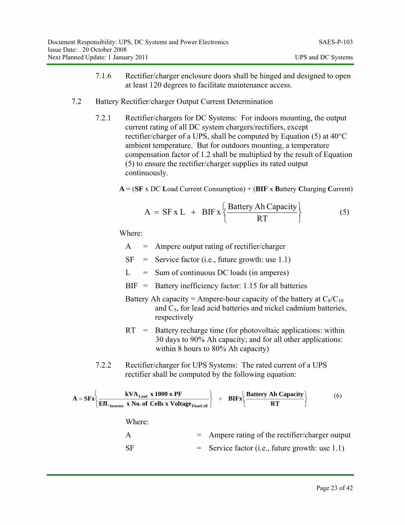
7.2.1 Rectifier/chargers for DC Systems: For indoors mounting, the output current rating of all DC system chargers/rectifiers, except rectifier/charger of a UPS, shall be computed by Equation (5) at 40°C ambient temperature. But for outdoors mounting, a temperature compensation factor of 1.2 shall be multiplied by the result of Equation (5) to ensure the rectifier/charger supplies its rated output continuously.
A = (SF x DC Load Current Consumption) + (BIF x Battery Charging Current)
⎭⎬⎫
⎩⎨⎧+=
RTCapacityAh Battery x BIF L x SF A (5)
Where:
A = Ampere output rating of rectifier/charger
SF = Service factor (i.e., future growth: use 1.1)
L = Sum of continuous DC loads (in amperes)
BIF = Battery inefficiency factor: 1.15 for all batteries
Battery Ah capacity = Ampere-hour capacity of the battery at C8/C10 and C5, for lead acid batteries and nickel cadmium batteries, respectively
RT = Battery recharge time (for photovoltaic applications: within 30 days to 90% Ah capacity; and for all other applications: within 8 hours to 80% Ah capacity)
7.2.2 Rectifier/charger for UPS Systems: The rated current of a UPS rectifier shall be computed by the following equation:
⎭⎬⎫
⎩⎨⎧+
⎭⎬⎫
⎩⎨⎧
=RT
CapacityAhBatteryBIFx
VoltagexCellsofNo.xEff.PFx1000xkVA
SFxAFloatCellInverter
Load (6)
Where:
A = Ampere rating of the rectifier/charger output
SF = Service factor (i.e., future growth: use 1.1)
Page 23 of 42
Document Responsibility: UPS, DC Systems and Power Electronics SAES-P-103 Issue Date: 20 October 2008 Next Planned Update: 1 January 2011 UPS and DC Systems
Page 24 of 42
kVALoad = Load designed apparent power (= Actual Load Power Consumption + Future Growth)
PF = Power factor of UPS load (use PF = 0.8 lagging)
Eff.Inverter = Efficiency of UPS inverter
No. of Cells = Number of series connected battery cells
VoltageFloatCell = Float voltage per battery cell
RT = Required recharge time of the system battery (use 8 hours for UPS applications)
BIF = Battery inefficiency factor (use 1.15 for all batteries)
Battery Ah Capacity = Ah capacity of battery at C8/C10 and C5, for lead acid battery and nickel cadmium battery, respectively
7.3 The Battery Charger /Rectifier shall be monitored remotely and be equipped with, but not limited to the following:
7.3.1 Battery charger / rectifier management software and hardware
7.3.2 Web-based monitoring facility
a) Card for network connection
b) Software for network management
c) Web/SNMP manager.
7.3.3 RS 232/RS 485 ports.
7.3.4 Battery management technology.
7.3.5 Environment sensor for SNMP/Web application (to monitor temperature and humidity).
8 Uninterruptible Power Supply (UPS) Systems
8.1 General
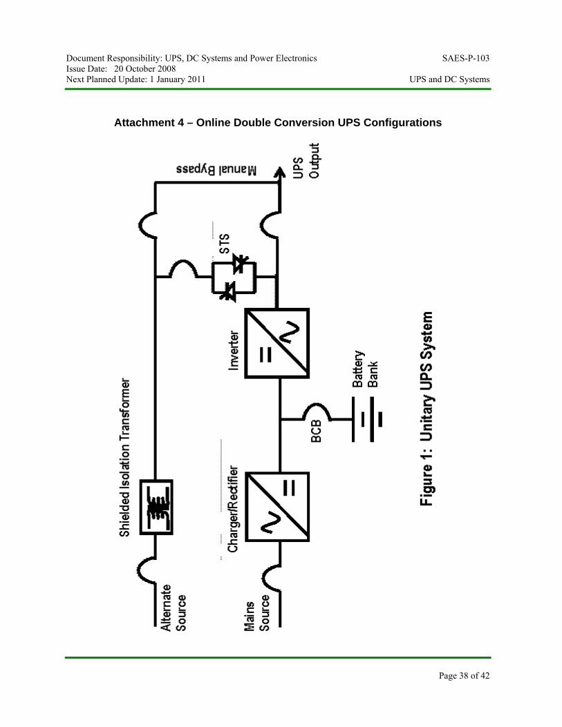
8.1.1 Based on the criticality of the load, either one of the following three online double conversion UPS configurations shall be specified (see Attachment 4):
Document Responsibility: UPS, DC Systems and Power Electronics SAES-P-103 Issue Date: 20 October 2008 Next Planned Update: 1 January 2011 UPS and DC Systems
Page 25 of 42
a. Single, non-redundant UPS configuration for critical loads (n); see Attachment 4 – Figure 1
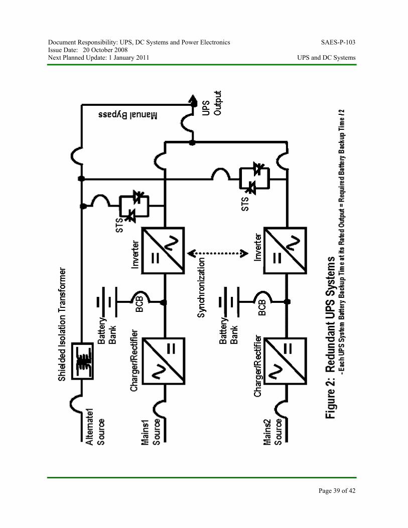
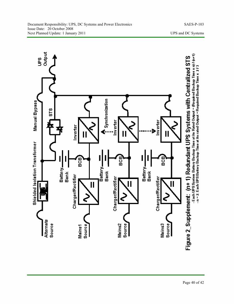
b. Parallel redundant UPS configuration for extremely critical loads (n+1); See Attachment 4 – Figure 2 and Figure2_Supplement
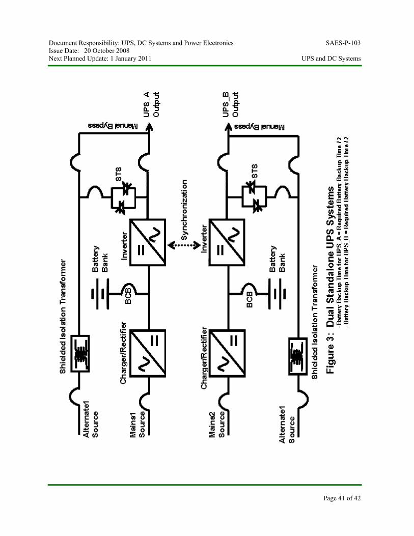
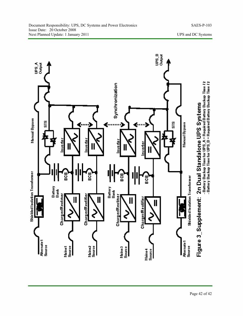
c. Dual standalone UPS configuration for loads that accept dual input feeders (2n); See Attachment 4 – Figure 3 and Figure3_Supplement
8.1.2 UPS rating larger than 10kVA shall comply with 17-SAMSS-516.
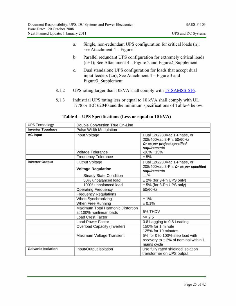
8.1.3 Industrial UPS rating less or equal to 10 kVA shall comply with UL 1778 or IEC 62040 and the minimum specifications of Table-4 below:
Table 4 – UPS Specifications (Less or equal to 10 kVA)
UPS Technology Double Conversion True On-Line Inverter Topology Pulse Width Modulation AC Input Input Voltage Dual 120/230Vac 1-Phase, or
208/400Vac 3-Ph, 50/60Hz Or as per project specified requirements
Voltage Tolerance -20% +15% Frequency Tolerance ± 5% Inverter Output Output Voltage
Voltage Regulation
Steady State Condition
Dual 120/230Vac 1-Phase, or 208/400Vac 3-Ph, Or as per specified requirements ±1%
50% unbalanced load ± 2% (for 3-Ph UPS only) 100% unbalanced load ± 5% (for 3-Ph UPS only) Operating Frequency 50/60Hz Frequency Regulations When Synchronizing ± 1% When Free Running ± 0.1% Maximum Total Harmonic Distortion
at 100% nonlinear loads 5% THDV
Load Crest Factor >= 2.5 Load Power Factor 0.8 Lagging to 0.8 Leading Overload Capacity (Inverter) 150% for 1 minute
125% for 10 minutes Maximum Voltage Transient 5% for 0 to 100% step load with
recovery to ± 2% of nominal within 1 mains cycle
Galvanic Isolation Input/Output isolation Use fully rated shielded isolation transformer on UPS output
Document Responsibility: UPS, DC Systems and Power Electronics SAES-P-103 Issue Date: 20 October 2008 Next Planned Update: 1 January 2011 UPS and DC Systems
Page 26 of 42
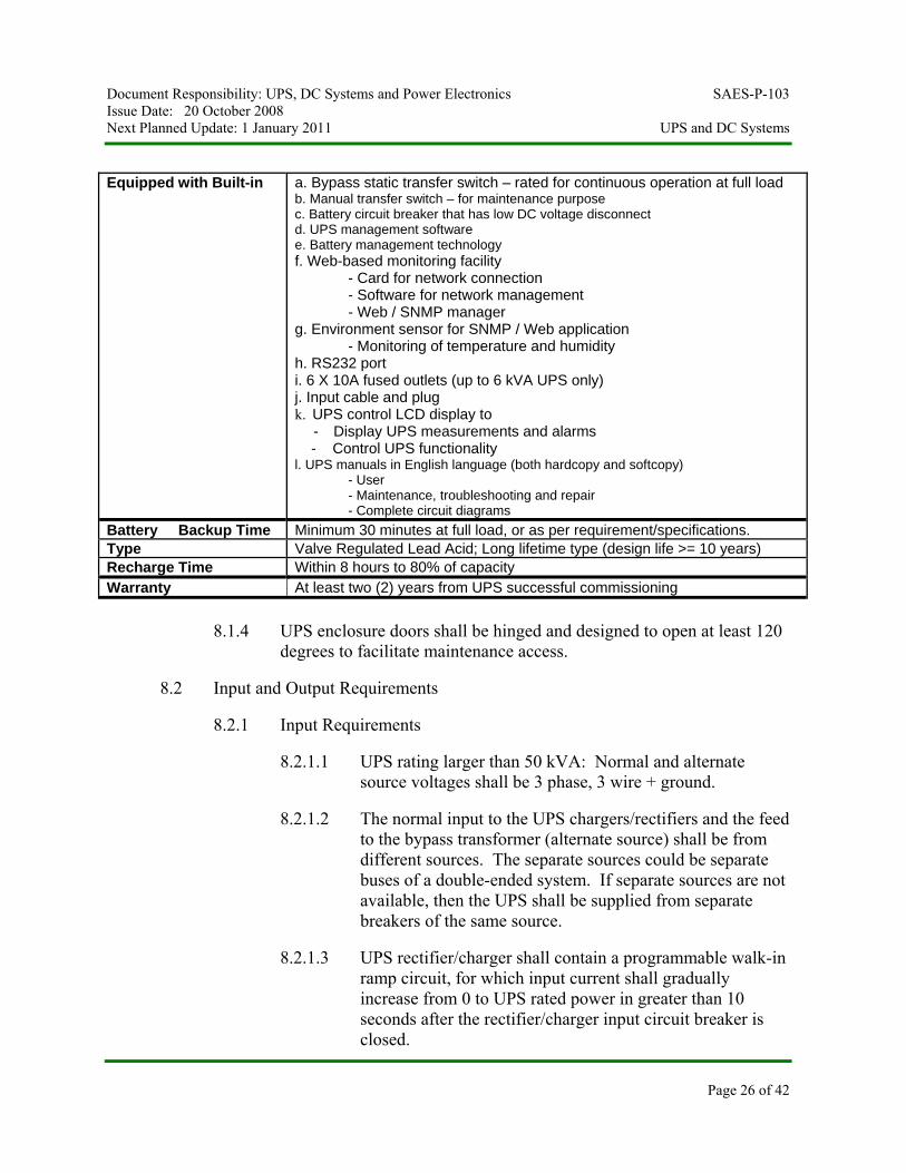
Equipped with Built-in a. Bypass static transfer switch – rated for continuous operation at full load
b. Manual transfer switch – for maintenance purpose c. Battery circuit breaker that has low DC voltage disconnect d. UPS management software e. Battery management technology f. Web-based monitoring facility
- Card for network connection - Software for network management - Web / SNMP manager
g. Environment sensor for SNMP / Web application - Monitoring of temperature and humidity
h. RS232 port i. 6 X 10A fused outlets (up to 6 kVA UPS only) j. Input cable and plug k. UPS control LCD display to
- Display UPS measurements and alarms - Control UPS functionality l. UPS manuals in English language (both hardcopy and softcopy)
- User - Maintenance, troubleshooting and repair - Complete circuit diagrams
Battery Backup Time Minimum 30 minutes at full load, or as per requirement/specifications. Type Valve Regulated Lead Acid; Long lifetime type (design life >= 10 years) Recharge Time Within 8 hours to 80% of capacity Warranty At least two (2) years from UPS successful commissioning
8.1.4 UPS enclosure doors shall be hinged and designed to open at least 120 degrees to facilitate maintenance access.
8.2 Input and Output Requirements
8.2.1 Input Requirements
8.2.1.1 UPS rating larger than 50 kVA: Normal and alternate source voltages shall be 3 phase, 3 wire + ground.
8.2.1.2 The normal input to the UPS chargers/rectifiers and the feed to the bypass transformer (alternate source) shall be from different sources. The separate sources could be separate buses of a double-ended system. If separate sources are not available, then the UPS shall be supplied from separate breakers of the same source.
8.2.1.3 UPS rectifier/charger shall contain a programmable walk-in ramp circuit, for which input current shall gradually increase from 0 to UPS rated power in greater than 10 seconds after the rectifier/charger input circuit breaker is closed.
Document Responsibility: UPS, DC Systems and Power Electronics SAES-P-103 Issue Date: 20 October 2008 Next Planned Update: 1 January 2011 UPS and DC Systems
Page 27 of 42
8.2.2 Output Requirements
8.2.2.1 UPS Systems Rating <= 50 kVA: 1 phase, 3 wire; or 3 phase, 4 wire, plus ground.
8.2.2.2 UPS Systems Rating > 50 kVA: 3 phase, 4 wire, plus ground.
8.3 Determination of kVA Rating
8.3.1 The power (kVA) rating of the UPS system shall be equal to or greater than the steady-state kVA of all the downstream loads plus a future load growth factor.
Commentary Note:
Because the UPS is current-limiting source, the UPS will not be capable of delivering inrush currents of large loads when starting during the utility power loss.
8.3.2 The load power factor (PF) of 0.8 lagging shall be considered in sizing the batteries for the UPS system. The UPS inverter shall be sized to deliver full rated power at 0.8 PF lagging without derating.
8.3.3 Every UPS system shall be equipped with the following inbuilt fully rated and designed for continuous operation: static bypass switch and maintenance (manual) bypass switch.
8.3.4 Steady-State Load Conditions: Determine the average power requirement of all downstream loads based on their operating duty cycle.
8.3.5 Transient Conditions: Determine the transient current peaks (inrush currents) and the time duration of such peaks which may occur during the start-up of all load devices. Analyze the UPS to determine if it can withstand the inrush current requirements of the loads based on the following overload capabilities:
a. UPS System Rating > 10 kVA: 150% for 1 minute (required by 17-SAMSS-516).
b. UPS System Rating <= 10 kVA: 150% for 1 minute (See Table-4 of this standard).
Commentary Note:
Refer to Attachment 2 for a typical example of UPS sizing with proper considerations for the inrush current requirement of loads.
Document Responsibility: UPS, DC Systems and Power Electronics SAES-P-103 Issue Date: 20 October 2008 Next Planned Update: 1 January 2011 UPS and DC Systems
Page 28 of 42
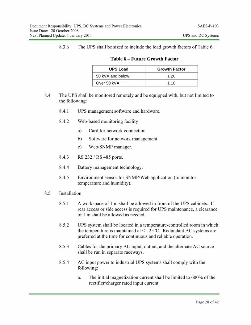
8.3.6 The UPS shall be sized to include the load growth factors of Table 6.
Table 6 – Future Growth Factor
UPS Load Growth Factor 50 kVA and below 1.20
Over 50 kVA 1.10
8.4 The UPS shall be monitored remotely and be equipped with, but not limited to the following:
8.4.1 UPS management software and hardware.
8.4.2 Web-based monitoring facility
a) Card for network connection
b) Software for network management
c) Web/SNMP manager.
8.4.3 RS 232 / RS 485 ports.
8.4.4 Battery management technology.
8.4.5 Environment sensor for SNMP/Web application (to monitor temperature and humidity).
8.5 Installation
8.5.1 A workspace of 1 m shall be allowed in front of the UPS cabinets. If rear access or side access is required for UPS maintenance, a clearance of 1 m shall be allowed as needed.
8.5.2 UPS system shall be located in a temperature-controlled room in which the temperature is maintained at <= 25°C. Redundant AC systems are preferred at the time for continuous and reliable operation.
8.5.3 Cables for the primary AC input, output, and the alternate AC source shall be run in separate raceways.
8.5.4 AC input power to industrial UPS systems shall comply with the following:
a. The initial magnetization current shall be limited to 600% of the rectifier/charger rated input current.
Document Responsibility: UPS, DC Systems and Power Electronics SAES-P-103 Issue Date: 20 October 2008 Next Planned Update: 1 January 2011 UPS and DC Systems
Page 29 of 42
b. The circuit breakers for both the primary and alternate AC sources shall be equipped with overcurrent protection while properly sized and coordinated with upstream and down stream protections (see paragraph 8.5.5).
Commentary Notes:
i) Include UPS overall efficiency and battery charging current on sizing rating of the primary feeder circuit breaker.
ii) Consider UPS inverter overload capability on sizing rating of the alternate feeder circuit breaker.
iii) Consult the UPS manufacturer on sizing of the input feeder circuit breaker if data is not available.
c. When a generator and automatic transfer switch arrangement is used to extend the protection time of a UPS system, it shall be connected to deliver power to the UPS rectifier and not directly to the critical load.
d. The UPS static switch shall be arranged to transfer the entire UPS load to the alternate AC source (bypass line) in the event of a malfunction of the inverter or to clear a load fault. After fault clearance, the load shall be transferred automatically from the mains supply to the UPS output supply.
e. The kVA rating of a backup generator used for supplying long term backup power to the UPS system shall be at least 2.25 times the rated kVA of the UPS.
Exception:
The emergency generator may be sized at 1.4 times the rated kVA of the UPS: Provided that the feedback injection of current harmonics by the UPS rectifier is limited to 5% THDI during all UPS operating conditions.
f. The UPS system shall automatically block (inhibit) the batteries charging during supply of power through the emergency generator.
8.5.5 UPS loads shall be distributed through panelboards. Protection for the outgoing circuits shall be accomplished through fast acting circuit breakers rated for continuous operation with capability to quickly open and clear short-circuit or overload conditions and have current limit feature.
Document Responsibility: UPS, DC Systems and Power Electronics SAES-P-103 Issue Date: 20 October 2008 Next Planned Update: 1 January 2011 UPS and DC Systems
Page 30 of 42
Commentary Note:
Panelboards specification does not allow the fuses to be within the panelboard enclosure. However, fast acting fuses type KTK or equivalent, if required to protect specific loads, would have to be installed in a separate enclosure.
8.5.6 Ratings of distribution panel's main feeder and branch circuits shall be coordinated with UPS and bypass ratings. The maximum current rating of the largest branch circuit breaker in the distribution panel shall be no greater than one-half the rated current output of the inverter. In the case of fuses, the largest load-side fuse shall be no greater than one-fourth the rated current output of the inverter. This is to ensure proper selectivity between the tripping of the load circuit protective devices and the inverter's internal protective devices.
8.5.7 The requirements of paragraph 8.5.6 shall not apply when the UPS is equipped with a static bypass switch for transferring to the bypass (alternate) line. In that case, the protective devices for the outgoing loads shall be selected to achieve selective coordination with the primary breaker on the line side of the bypass transformer.
8.5.8 Branch circuit breakers shall be coordinated with the load crest factor (in-rush current) as applicable.
8.5.9 A bolted fault test (three phases connected to ground) shall be conducted on the UPS distribution system to establish that proper fuse coordination has been achieved. Conduct the test by placing a bolted fault, by means of a contactor, on a typical branch circuit of the UPS distribution system. The branch circuit fuse shall clear the fault without affecting any upstream fuses and circuit breakers.
9 Photovoltaic (Solar) Systems
9.1 Installation
9.1.1 Solar photovoltaic systems shall be installed in accordance with NFPA 70, Article 690 or IEC equivalent standard, as applicable.
9.1.2 The metallic frames and support structures of photovoltaic panels shall be grounded in accordance with SAES-P-111.
9.1.3 Enclosures housing electronic equipment and batteries shall be shaded from direct sunlight regardless of the sun inclination angle. Minimum enclosure protection class for all outdoors mounting applications shall be NEMA 250 Type 4X (or IEC 60529 IP 65).
Document Responsibility: UPS, DC Systems and Power Electronics SAES-P-103 Issue Date: 20 October 2008 Next Planned Update: 1 January 2011 UPS and DC Systems
Page 31 of 42
9.1.4 Each solar photovoltaic module shall be equipped with a Shottky blocking diode to prevent reverse flow of power into the photovoltaic module.
9.1.5 Solar photovoltaic array shall be installed at a tilt (inclination) angle equal to the latitude of the location plus 10-15 degrees.
9.1.6 Solar photovoltaic array shall be directed toward the geographical south (± 5 degrees).
9.1.7 Battery shall be selected for minimum topping-up interval of 1 year, at 25°C operating temperature and float charging.
9.1.8 Battery shall be selected for photovoltaic application with a cycling life of at least 8000 cycles to a shallow cycle of 20% depth of discharge (DOD), and 1000 cycles to 80% DOD.
9.1.9 Batteries shall be photovoltaic-graded type to tolerate Saudi Arabia harsh weather conditions; the ambient temperature may reach 50°C.
9.2 Charge Regulator (Controller)
9.2.1 The charge regulator shall be designed to provide two-step (stage) charging for the batteries (float charging and boost charging) and to provide the power requirements of the load when the photovoltaic solar array is producing power. On-off type regulators, which simply disconnect the solar array from the entire system when the battery reaches a certain terminal voltage, are not acceptable.
9.2.2 The charge regulators shall be of the solid-state design.
9.2.3 The charge regulator shall be designed to operate continuously at full rate in ambient temperatures between 0 and 50°C.
9.2.4 The charge regulator shall be equipped with a Shottky blocking diode to prevent reverse flow of power into a faulty regulator.
9.2.5 The charge regulator shall be equipped with temperature compensation feature to adjust the charging voltage with temperature.
9.2.6 The charge regulator shall be equipped with a low-voltage battery disconnect which shall act to disconnect the load from the battery when the battery reaches the end-of-discharge voltage (1.85 Volts per cell for lead-acid batteries and1.14 Volts per cell for nickel-cadmium batteries) to prevent severe battery discharge. Battery manufacturer's recommended cell end of discharge voltage shall be followed.
Document Responsibility: UPS, DC Systems and Power Electronics SAES-P-103 Issue Date: 20 October 2008 Next Planned Update: 1 January 2011 UPS and DC Systems
Page 32 of 42
9.2.7 The charge regulator shall include the following instrumentation and alarms:
a. Battery voltage;
b. Battery current (charging or discharging);
c. Solar array current (for each array);
d. Load current;
e. Local indication of high and low battery voltage plus normally open and normally closed voltage free contacts for activating remote alarms;
f. All alarms shall be indicated on the charge regulator cabinet and a set of normally open and normally closed voltage free contacts shall be provided for annunciating the alarms to a central control room via Remote Terminal Units (RTUs) or similar facilities, where such facilities are available.
9.2.8 All controls and instrumentation shall be housed in a NEMA 250 Type 4X (or IEC 60529 IP 65) enclosure.
9.2.9 Surge protection shall be provided for the DC load bus.
9.3 Sizing
Solar photovoltaic power system shall be sized as follows:
9.3.1 Battery sizing shall be per paragraph 5.3. Maximum autonomy (backup) time shall be 5 days or as per application requirement.
9.3.2 Charge regulator shall be rated for the maximum array current plus 10% design margin.
9.3.3 Solar photovoltaic array shall be sized with the following factors:
9.3.3.1 The solar array shall be sized to fully recharge the battery to 90% state of charge in 30 days.
9.3.3.2 The array shall be sized based on 5 effective sun hours for all installations in Saudi Arabia.
9.3.3.3 The array size shall be derated 10% for dust accumulation.
9.3.3.4 The array size shall be derated 10% for aging over the array expected useful life.
Document Responsibility: UPS, DC Systems and Power Electronics SAES-P-103 Issue Date: 20 October 2008 Next Planned Update: 1 January 2011 UPS and DC Systems
Page 33 of 42
9.3.3.5 The array sizing shall include additional 10% capacity for future growth.
10 Battery Tests and Records
10.1 The initial battery capacity test and commissioning records are pertinent to the maintenance and optimum operational life of the battery. All commissioning data shall be dated, recorded, and maintained in a permanent file to facilitate required future maintenance and interpretation of the operating data. The following data shall be maintained in a permanent record file:
a. Initial battery capacity test performed in accordance with IEEE 450 (for lead acid), IEEE 1106 (for nickel cadmium), or IEEE 1188 (for VRLA) or the IEC equivalent standard, as applicable.
b. The initial resistance values of the intercell connections.
c. The initial individual cell voltages and specific gravity measurements.
10.2 Routine battery maintenance and testing shall be in accordance to SAEP-350. Revision Summary 7 December 2005 Major revision. 22 February 2006 Minor revision. 13 August 2007 Minor revision. 2 June 2008 Editorial revision. 20 October 2008 Editorial revision to replace UPS, DC Systems and Power Electronics Standards
Committee Chairman and Vice Chairman.
Document Responsibility: UPS, DC Systems and Power Electronics SAES-P-103 Issue Date: 20 October 2008 Next Planned Update: 1 January 2011 UPS and DC Systems
Page 34 of 42
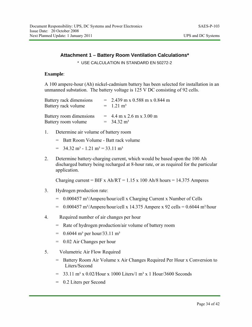
Attachment 1 – Battery Room Ventilation Calculations* * USE CALCULATION IN STANDARD EN 50272-2
Example:
A 100 ampere-hour (Ah) nickel-cadmium battery has been selected for installation in an unmanned substation. The battery voltage is 125 V DC consisting of 92 cells.
Battery rack dimensions = 2.439 m x 0.588 m x 0.844 m Battery rack volume = 1.21 m³
Battery room dimensions = 4.4 m x 2.6 m x 3.00 m Battery room volume = 34.32 m³
1. Determine air volume of battery room
= Batt Room Volume - Batt rack volume
= 34.32 m³ - 1.21 m³ = 33.11 m³
2. Determine battery-charging current, which would be based upon the 100 Ah discharged battery being recharged at 8-hour rate, or as required for the particular application.
Charging current = BIF x Ah/RT = 1.15 x 100 Ah/8 hours = 14.375 Amperes
3. Hydrogen production rate:
= 0.000457 m³/Ampere/hour/cell x Charging Current x Number of Cells
= 0.000457 m³/Ampere/hour/cell x 14.375 Ampere x 92 cells = 0.6044 m³/hour
4. Required number of air changes per hour
= Rate of hydrogen production/air volume of battery room
= 0.6044 m³ per hour/33.11 m³
= 0.02 Air Changes per hour
5. Volumetric Air Flow Required
= Battery Room Air Volume x Air Changes Required Per Hour x Conversion to Liters/Second
= 33.11 m³ x 0.02/Hour x 1000 Liters/1 m³ x 1 Hour/3600 Seconds
= 0.2 Liters per Second
Document Responsibility: UPS, DC Systems and Power Electronics SAES-P-103 Issue Date: 20 October 2008 Next Planned Update: 1 January 2011 UPS and DC Systems
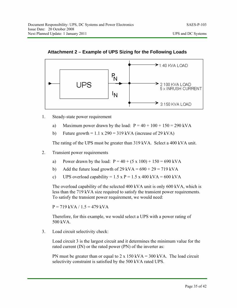
Attachment 2 – Example of UPS Sizing for the Following Loads
1. Steady-state power requirement
a) Maximum power drawn by the load: P = 40 + 100 + 150 = 290 kVA
b) Future growth = 1.1 x 290 = 319 kVA (increase of 29 kVA)
The rating of the UPS must be greater than 319 kVA. Select a 400 kVA unit.
2. Transient power requirements
a) Power drawn by the load: P = 40 + (5 x 100) + 150 = 690 kVA
b) Add the future load growth of 29 kVA = 690 + 29 = 719 kVA
c) UPS overload capability = 1.5 x P = 1.5 x 400 kVA = 600 kVA
The overload capability of the selected 400 kVA unit is only 600 kVA, which is less than the 719 kVA size required to satisfy the transient power requirements. To satisfy the transient power requirement, we would need:
P = 719 kVA / 1.5 = 479 kVA
Therefore, for this example, we would select a UPS with a power rating of 500 kVA.
3. Load circuit selectivity check:
Load circuit 3 is the largest circuit and it determines the minimum value for the rated current (IN) or the rated power (PN) of the inverter as:
PN must be greater than or equal to 2 x 150 kVA = 300 kVA. The load circuit selectivity constraint is satisfied by the 500 kVA rated UPS.
Page 35 of 42
Document Responsibility: UPS, DC Systems and Power Electronics SAES-P-103 Issue Date: 20 October 2008 Next Planned Update: 1 January 2011 UPS and DC Systems
Page 36 of 42
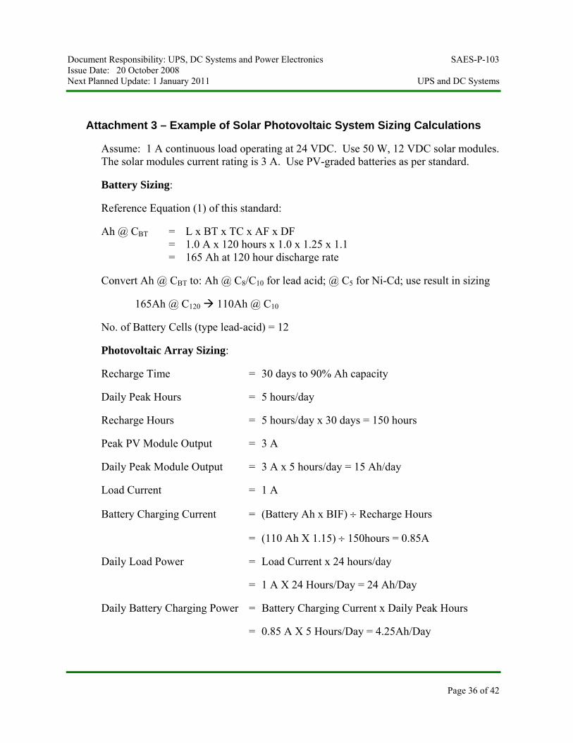
Attachment 3 – Example of Solar Photovoltaic System Sizing Calculations
Assume: 1 A continuous load operating at 24 VDC. Use 50 W, 12 VDC solar modules. The solar modules current rating is 3 A. Use PV-graded batteries as per standard.
Battery Sizing:
Reference Equation (1) of this standard:
Ah @ CBT = L x BT x TC x AF x DF = 1.0 A x 120 hours x 1.0 x 1.25 x 1.1 = 165 Ah at 120 hour discharge rate
Convert Ah @ CBT to: Ah @ C8/C10 for lead acid; @ C5 for Ni-Cd; use result in sizing
165Ah @ C120 110Ah @ C10
No. of Battery Cells (type lead-acid) = 12
Photovoltaic Array Sizing:
Recharge Time = 30 days to 90% Ah capacity
Daily Peak Hours = 5 hours/day
Recharge Hours = 5 hours/day x 30 days = 150 hours
Peak PV Module Output = 3 A
Daily Peak Module Output = 3 A x 5 hours/day = 15 Ah/day
Load Current = 1 A
Battery Charging Current = (Battery Ah x BIF) ÷ Recharge Hours
= (110 Ah X 1.15) ÷ 150hours = 0.85A
Daily Load Power = Load Current x 24 hours/day
= 1 A X 24 Hours/Day = 24 Ah/Day
Daily Battery Charging Power = Battery Charging Current x Daily Peak Hours
= 0.85 A X 5 Hours/Day = 4.25Ah/Day
Document Responsibility: UPS, DC Systems and Power Electronics SAES-P-103 Issue Date: 20 October 2008 Next Planned Update: 1 January 2011 UPS and DC Systems
Page 37 of 42
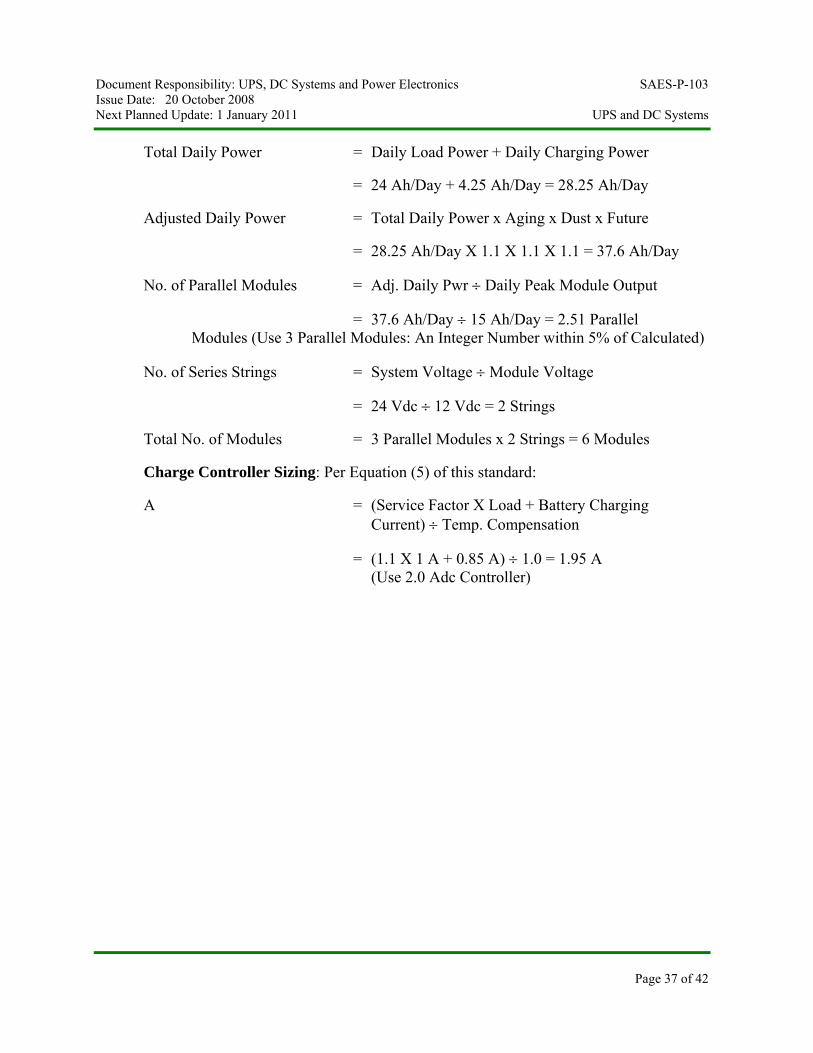
Total Daily Power = Daily Load Power + Daily Charging Power
= 24 Ah/Day + 4.25 Ah/Day = 28.25 Ah/Day
Adjusted Daily Power = Total Daily Power x Aging x Dust x Future
= 28.25 Ah/Day X 1.1 X 1.1 X 1.1 = 37.6 Ah/Day
No. of Parallel Modules = Adj. Daily Pwr ÷ Daily Peak Module Output
= 37.6 Ah/Day ÷ 15 Ah/Day = 2.51 Parallel Modules (Use 3 Parallel Modules: An Integer Number within 5% of Calculated)
No. of Series Strings = System Voltage ÷ Module Voltage
= 24 Vdc ÷ 12 Vdc = 2 Strings
Total No. of Modules = 3 Parallel Modules x 2 Strings = 6 Modules
Charge Controller Sizing: Per Equation (5) of this standard:
A = (Service Factor X Load + Battery Charging Current) ÷ Temp. Compensation
= (1.1 X 1 A + 0.85 A) ÷ 1.0 = 1.95 A (Use 2.0 Adc Controller)
Document Responsibility: UPS, DC Systems and Power Electronics SAES-P-103 Issue Date: 20 October 2008 Next Planned Update: 1 January 2011 UPS and DC Systems
Attachment 4 – Online Double Conversion UPS Configurations
Page 38 of 42
Document Responsibility: UPS, DC Systems and Power Electronics SAES-P-103 Issue Date: 20 October 2008 Next Planned Update: 1 January 2011 UPS and DC Systems
Page 39 of 42
Document Responsibility: UPS, DC Systems and Power Electronics SAES-P-103 Issue Date: 20 October 2008 Next Planned Update: 1 January 2011 UPS and DC Systems
Page 40 of 42
Document Responsibility: UPS, DC Systems and Power Electronics SAES-P-103 Issue Date: 20 October 2008 Next Planned Update: 1 January 2011 UPS and DC Systems
Page 41 of 42
Document Responsibility: UPS, DC Systems and Power Electronics SAES-P-103 Issue Date: 20 October 2008 Next Planned Update: 1 January 2011 UPS and DC Systems
Page 42 of 42