Embed Size (px)
Citation preview
Previous Issue: 15 August 2012 Next Planned Update: 15 August 2017
Page 1 of 17
Primary contact: Hamrani, Majed Muhsen on 966-3-8760282
Copyright©Saudi Aramco 2012. All rights reserved.
Engineering Standard
SAES-P-100 18 September 2012
Basic Power System Design Criteria
Document Responsibility: Electrical Systems Designs & Automation Standards Committee
Saudi Aramco DeskTop Standards
Table of Contents
1 Scope............................................................ 2
2 Conflicts and Deviations................................ 2
3 References.................................................... 2
4 Definitions...................................................... 3
5 General.......................................................... 6
6 Design Basis................................................. 8
7 System Studies........................................... 10
8 Electrical Area Classification Design........... 14
9 Environmental Conditions........................... 16
Document Responsibility: Electrical Systems Designs and Automation Standards Committee SAES-P-100
Issue Date: 18 September 2012
Next Planned Update: 15 August 2017 Basic Power System Design Criteria
Page 2 of 17
1 Scope
This SAES prescribes mandatory design bases and performance criteria of electrical
power systems. This SAES is intended to assist engineers and designers in those areas
not specifically referenced in other Saudi Aramco SAESs, SAMSSs, etc.
This document may not be attached to nor made a part of purchase orders.
2 Conflicts and Deviations
2.1 Any conflicts between this Standard and other Mandatory Saudi Aramco
Engineering Requirements (MSAERs*) or referenced industry standards shall be
identified to the Company or Buyer Representative who will request the
Manager, Consulting Services Department of Saudi Aramco, Dhahran to resolve
the conflict.
2.2 Direct all requests to deviate from this Standard in writing to the Company or
Buyer Representative, who shall follow internal company procedure SAEP-302
and forward Waiver Request to the Manager, Consulting Services Department
of Saudi Aramco, Dhahran requesting his approval.
2.3 The designation “Commentary” is used to label a sub-paragraph that contains
comments that are explanatory or advisory. These comments are not mandatory,
except to the extent that they explain mandatory requirements contained in this
SAES.
3 References
The selection of material and equipment, and the design, construction, maintenance, and
repair of equipment and facilities covered by this standard shall comply with the latest
edition of the references listed below, unless otherwise noted.
Saudi Aramco References
The following is a list of Mandatory Saudi Aramco Engineering Requirements
(MSAERs) which are specifically related to the design, specification, and installation
of electrical power systems and equipment. In addition, other MSAERs for related
disciplines shall be used in conjunction with those listed below as required.
o Saudi Aramco Engineering Procedure
SAEP-302 Instructions for Obtaining a Waiver of a Mandatory
Saudi Aramco Engineering Requirement
Document Responsibility: Electrical Systems Designs and Automation Standards Committee SAES-P-100
Issue Date: 18 September 2012
Next Planned Update: 15 August 2017 Basic Power System Design Criteria
Page 3 of 17
o Saudi Aramco Engineering Standards
SAES-A-112 Meteorological and Seismic Design Data
SAES-B-009 Fire Protection & Safety Requirements for Offshore
Production Facilities
SAES-B-014 Safety Requirements for Plant and Operations
Support Buildings
SAES-B-017 Fire Water System Design
SAES-B-064 Onshore and Nearshore Pipeline Safety
SAES-B-068 Electrical Area Classification
SAES-K-001 Heating, Ventilating and Air Conditioning (HVAC)
SAES-K-002 Air Conditioning Systems for Essential Operating
Facilities
SAES-O-202 Security Fencing
SAES-O-207 Power Supply for Security Systems
SAES-P-103 Batteries and U.P.S. Systems
SAES-P-111 Grounding
SAES-P-114 Power System and Equipment Protection
SAES-P-116 Switchgear and Control Equipment
SAES-P-123 Lighting
o Saudi Aramco General Instruction
GI-0002.717 Procedures and Guidelines for Handling
Polychlorinated Biphenyls (PCB's)
GI-0002.721 Electrical Arc Flash Hazard Mitigation
4 Definitions
Approval or Approved: Written approval of the ESD Coordinator.
Base Voltage: The bus voltage calculated by starting with the nominal voltage at the
swing bus and calculated for each bus based on the transformer turns ratios.
Bus Tie Breaker: A breaker used to connect the two busses of secondary-selective
system.
Captive Transformer: A transformer whose output is dedicated to a single piece of
utilization equipment.
Document Responsibility: Electrical Systems Designs and Automation Standards Committee SAES-P-100
Issue Date: 18 September 2012
Next Planned Update: 15 August 2017 Basic Power System Design Criteria
Page 4 of 17
Controlgear: Equipment manufactured to either 16-SAMSS-503 (Low Voltage
Controlgear), 16-SAMSS-506 (High Voltage Controlgear) or 16-SAMSS-507 (High
Voltage Motor Controller - Outdoor).
Critical Loads: Are loads:
a) Where a single contingency failure could cause a loss of power which would
create an immediate hazard to human life.
b) Security systems classified in SAES-O-207.
c) Which cannot be shut-down for a minimum of five consecutive days annually for
scheduled maintenance on upstream power supply equipment.
Examples of critical loads are: major computer centers, critical care areas in clinics and
hospitals, major office buildings, process units in gas plants and refineries.
Demand: Electrical load averaged over a specified time period.
Distribution Equipment: Equipment used to distribute power to utilization equipment
or other distribution equipment. For example switchgear, controlgear, panelboards,
switchracks, switchboards, etc.
ESD Coordinator: Coordinator, Electrical Systems Division, Consulting Services
Department.
High Voltage: Voltages 1000 V or greater unless otherwise designated in a specific
MSAER or referenced international standard.
Commentary Note:
The term medium voltage is no longer being used in most North American and essentially all European (IEC) standards. Where used, it generally refers to system voltages greater than 1 kV but less than 100 kV. As used in Saudi Aramco, medium voltage generally refers to voltages 2.4 kV and above but less than 34.5 kV.
Industrial Facilities: Includes the following:
a) Facilities directly associated with production, processing, or bulk distribution of
hydrocarbons. This includes, but is not limited to, facilities such as the following:
i) Pumping or compression facilities in GOSPs
ii) Water injection plants
iii) Refineries
iv) Bulk distribution plants
v) Pumping stations
Document Responsibility: Electrical Systems Designs and Automation Standards Committee SAES-P-100
Issue Date: 18 September 2012
Next Planned Update: 15 August 2017 Basic Power System Design Criteria
Page 5 of 17
vi) Gas plants.
b) Hospitals.
c) Office buildings exceeding three occupied floors.
d) Control buildings.
Inside-Plant: Facilities within the perimeter security fencing installed per the SAES-O
series of standards.
Low Voltage: Voltages less than 1000 V, unless otherwise designated in a specific
MSAER or referenced international standard.
MSAER: Mandatory Saudi Aramco Engineering Requirements.
Examples of MSAERs are Saudi Aramco Materials System Specifications (SAMSSs),
Engineering Standards (SAESs) and Standard Drawings (SASDs).
Nominal Voltage: Refer to Table 1.
Operating Load:
a) For new facilities: Anticipated one-hour demand based on plant or facility design
conditions.
b) For existing facilities: When data from metering equipment is available:
Maximum 60-minute demand measured over a minimum of one year.
Commentary Note:
Depending on the nature of the loads, the operating load may be substantially less than the total connected load.
Outside-Plant: Facilities outside of the perimeter security fencing installed per the
SAES-O series of standards.
PCB free: Containing less than 1 ppm Polychlorinated biphenyl.
Plant: Facility requiring perimeter security fencing installed per the SAES-O series of
standards.
SAMSS: Saudi Aramco Materials System Specification.
SBC: Saudi Building Code
Secondary-Selective: A switchgear assembly consisting of two buses connected
with a single bus tie breaker. Each bus has one breaker to receive incoming power.
(i.e., power flow into and between the two busses is controlled with three breakers).
Document Responsibility: Electrical Systems Designs and Automation Standards Committee SAES-P-100
Issue Date: 18 September 2012
Next Planned Update: 15 August 2017 Basic Power System Design Criteria
Page 6 of 17
These schemes are standardized. Refer to SAES-P-116 for standardized schemes.
Secondary-selective Substation: A substation fed by two independent power sources
(different transmission or distribution lines) which consists of one or more sets of two
transformers and associated secondary-selective switchgear. Also referred to as a
“double-ended” substation.
Severe Corrosive Environment: As described in Section 9 of this standard.
Switchgear: Equipment manufactured to either 16-SAMSS-502 (Low Voltage
Switchgear) or 16-SAMSS-504 (High Voltage Switchgear).
Switchrack: Equipment manufactured per 16-SAMSS-512.
UPS: Uninterruptible Power Supply.
Utilization device/equipment: Equipment whose primary function is to convert
electrical energy to another form or store electrical energy. Examples of utilization
equipment would be motors, heaters, lamps, batteries, etc. Equipment directly
feeding/controlling the utilization equipment is considered part of the utilization
equipment (e.g., AFDs, reduced voltage starters, battery chargers, etc.).
Vital Equipment: As defined by the Saudi Arabian Government High Commission for
Industrial Security. The definition is stated in Sections 4.9 of SAES-O-202.
5 General
5.1 Terms in bold font are defined within Section 4.
5.2 Basic Design Codes
Electrical power systems shall be designed and constructed in accordance with
the latest edition of Volume 4 of SBC, NFPA 70 (National Electrical Code),
NFPA 70 E (Standard for Electrical Safety in the Workplace) and ANSI C2
(National Electrical Safety Code), as supplemented or modified by the Saudi
Aramco Engineering Standards. In general, SBC supersedes other codes except
when specifically stated within any of the MSAER documents.
5.3 Low voltage AC distribution systems shall be protected by circuit breakers.
Fuses shall not be used.
Exception:
Molded case circuit breakers with integral current limiting fuses are permitted and fuses are permitted for protection of circuits fed from UPS systems.
Document Responsibility: Electrical Systems Designs and Automation Standards Committee SAES-P-100
Issue Date: 18 September 2012
Next Planned Update: 15 August 2017 Basic Power System Design Criteria
Page 7 of 17
5.4 All interrupting devices shall be fully rated for the short circuit duty. Refer to
SAES-P-116 for additional details and exceptions.
Commentary Note:
This means, for example, that designs based upon series-rated or cascade-rated equipment shall not be used.
5.5 Only secondary-selective switchgear shall be used to feed critical loads.
Exception:
Critical facilities or equipment fed from a single-ended substation bus which has a standby generator capable of automatically supplying the required power to the bus within 10 seconds after a power failure are permitted with approval.
5.6 Loads to be supplied by standby power or emergency power include the
following:
Commentary Note:
Regardless of how standby or emergency power is defined in other standards or codes, this section covers alternative continuous power supply when the normal power of a facility – typically received from power utility, third party IPPs, or in-house generation – is lost.
Security system loads specified in SAES-O-207.
Occupied rooms intended for use during emergencies such as emergency
control room or disaster response room.
HVAC and air handling control equipment for pressurized buildings as
specified in SAES-B-014 and SAES-K-002.
Emergency lighting as mandated in SAES-P-123, if DC power or UPS is not
sufficient for the intended purpose.
Essential loads that cannot be supplied from UPS or DC system when
approved by ESD Coordinator.
5.7 Sizing of the electrical system shall be based upon using 110% of the sum of the
operating load plus all known future loads.
5.8 Electrical equipment for fire pump installations shall meet the requirements of
NFPA 20 except as modified by the following MSAERs:
SAES-B-009 Fire Protection & Safety Requirements for
Offshore Production Facilities
SAES-B-017 Fire Water System Design
Document Responsibility: Electrical Systems Designs and Automation Standards Committee SAES-P-100
Issue Date: 18 September 2012
Next Planned Update: 15 August 2017 Basic Power System Design Criteria
Page 8 of 17
SAES-P-116 Switchgear and Control Equipment
5.9 Existing equipment containing PCB shall be handled in accordance with
GI-0002.717. Insulating materials, insulating liquids, etc., in new equipment
shall be PCB-free.
5.10 Interfaces with communications systems shall be in accordance with
SAES-T- and SAES-Z-Series.
5.11 “Approval” or “authority having jurisdiction” issues contained with the SBC or
other codes shall be referred to the Consulting Services Department / Electrical
Systems Division for resolution.
6 Design Basis
6.1 System Voltage and Frequency
6.1.1 The frequency of alternating current electrical power systems shall be
60 Hz.
Exception:
Existing facilities with 50 Hz power systems (including 50 Hz systems with nominal voltages which do not comply with Table 1) and additions, replacements, etc., to these systems that do not result in a requirement to add 50 Hz generation capacity, are permitted.
6.1.2 The primary distribution within industrial facilities shall be 13.8 kV,
three-phase, three-wire. Secondary distribution shall be either 4160 V,
three phase, three wire and/or 480 V, three phase three wire.
Exception:
A 4160 V primary distribution system is acceptable if derived from a transformer(s) fed at a nominal voltage of 69 kV or greater.
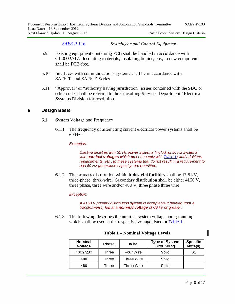
6.1.3 The following describes the nominal system voltage and grounding
which shall be used at the respective voltage listed in Table 1.
Table 1 – Nominal Voltage Levels
Nominal Voltage
Phase Wire Type of System
Grounding Specific Note(s)
400Y/230 Three Four Wire Solid S1
400 Three Three Wire Solid
480 Three Three Wire Solid
Document Responsibility: Electrical Systems Designs and Automation Standards Committee SAES-P-100
Issue Date: 18 September 2012
Next Planned Update: 15 August 2017 Basic Power System Design Criteria
Page 9 of 17
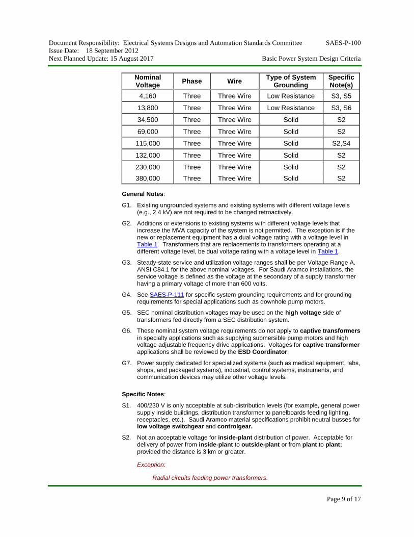
Nominal Voltage
Phase Wire Type of System
Grounding Specific Note(s)
4,160 Three Three Wire Low Resistance S3, S5
13,800 Three Three Wire Low Resistance S3, S6
34,500 Three Three Wire Solid S2
69,000 Three Three Wire Solid S2
115,000 Three Three Wire Solid S2,S4
132,000 Three Three Wire Solid S2
230,000 Three Three Wire Solid S2
380,000 Three Three Wire Solid S2
General Notes:
G1. Existing ungrounded systems and existing systems with different voltage levels (e.g., 2.4 kV) are not required to be changed retroactively.
G2. Additions or extensions to existing systems with different voltage levels that increase the MVA capacity of the system is not permitted. The exception is if the new or replacement equipment has a dual voltage rating with a voltage level in Table 1. Transformers that are replacements to transformers operating at a different voltage level, be dual voltage rating with a voltage level in Table 1.
G3. Steady-state service and utilization voltage ranges shall be per Voltage Range A, ANSI C84.1 for the above nominal voltages. For Saudi Aramco installations, the service voltage is defined as the voltage at the secondary of a supply transformer having a primary voltage of more than 600 volts.
G4. See SAES-P-111 for specific system grounding requirements and for grounding requirements for special applications such as downhole pump motors.
G5. SEC nominal distribution voltages may be used on the high voltage side of
transformers fed directly from a SEC distribution system.
G6. These nominal system voltage requirements do not apply to captive transformers
in specialty applications such as supplying submersible pump motors and high voltage adjustable frequency drive applications. Voltages for captive transformer applications shall be reviewed by the ESD Coordinator.
G7. Power supply dedicated for specialized systems (such as medical equipment, labs, shops, and packaged systems), industrial, control systems, instruments, and communication devices may utilize other voltage levels.
Specific Notes:
S1. 400/230 V is only acceptable at sub-distribution levels (for example, general power supply inside buildings, distribution transformer to panelboards feeding lighting, receptacles, etc.). Saudi Aramco material specifications prohibit neutral busses for low voltage switchgear and controlgear.
S2. Not an acceptable voltage for inside-plant distribution of power. Acceptable for delivery of power from inside-plant to outside-plant or from plant to plant;
provided the distance is 3 km or greater.
Exception:
Radial circuits feeding power transformers.
Document Responsibility: Electrical Systems Designs and Automation Standards Committee SAES-P-100
Issue Date: 18 September 2012
Next Planned Update: 15 August 2017 Basic Power System Design Criteria
Page 10 of 17
S3. Solidly grounded system shall be specified for feeders feeding overhead lines. If the system is feeding combination of overhead lines and other loads, dedicated transformer or special transformer shall be considered and approved by ESD Coordinator.
S4 This also includes system operating at 110 kV.
S5. 400 A, 10 second resistor.
S6. 400 A or 1000A, 10 second resistor.
6.2 Steady state voltage range, under all study conditions, shall be as follows:
6.2.1 Low Voltage Systems
i) At branch circuit/distribution equipment connection points
(e.g., switchgear, controlgear, panelboards, switchracks, etc.):
95% to 105% of nominal voltage.
ii) At light fixtures: 91.7% to 104.2% of nominal voltage.
iii) At utilization equipment other than lights: 90% to 104.2% of
nominal voltage.
6.2.2 High Voltage Systems
i) Originating and ending in the same plant:
a) At branch circuit/distribution equipment connection points
(e.g., switchgear, controlgear, etc.): 97.5% to 105% of
nominal voltage.
b) At the utilization device: 90% to 105% of nominal voltage.
ii) Originating and ending in different plants or facilities.
At main distribution equipment (e.g., switchgear): 95% to
105% of nominal voltage.
6.3 Voltage Drop associated with Motor Starting
6.3.1 When a motor is started, the voltage at every utilization device,
anywhere in the electrical system, shall not drop below 85% of the
nominal voltage. Where the utilization equipment is modeled as
lumped load at the distribution bus, the voltage at the distribution
equipment level shall not drop below 90% of the nominal voltage.
6.3.2 When a motor is started, the voltage at the terminals of the motor being
started shall not drop below 85% of the rated motor voltage.
Document Responsibility: Electrical Systems Designs and Automation Standards Committee SAES-P-100
Issue Date: 18 September 2012
Next Planned Update: 15 August 2017 Basic Power System Design Criteria
Page 11 of 17
Exception:
For high voltage motors, when approved, a drop to 80% of rated motor voltage is permitted at the terminals of the motor being started.
6.4 Direct Current Systems
Maximum total voltage drop for main, feeder, and branch circuits shall not
exceed 5%. The average voltage drop in branch circuits shall not exceed 2%
with a maximum of 4% at the most distant load.
7 System Studies
System studies are required for new facilities and major additions to existing facilities.
If uncertain whether the additions to existing facilities are “major,” contact the ESD
Coordinator. The Electrical Transient Analyzer Program (ETAP) shall be used to
conduct the studies outlined in Section 7.5. Input and output data files shall be
furnished to the facility proponent's engineering organization for new facilities and any
(major or minor) addition to existing facilities. Alternative software may be used
without a need for waiver or approval if the network database (load flow, dynamic
data, and network diagrams) can be read directly by ETAP without a need for any
middleware tools. Written statement by the contractor or design office shall be
provided indicating that data files are directly inter-faceable with ETAP.
7.1 Actual system data and constraints shall be used for all studies.
Commentary Note:
The ultimate, maximum, and minimum short circuit levels at utility interface point should be obtained prior of commencing system studies.
7.2 When modeling the system for different studies, it is acceptable to assume that
the off-load transformer taps can be set one step off the neutral position. In this
case, all studies shall use the same transformer tap position.
7.3 It is acceptable to use on-load tap changer, which will automatically regulate the
voltage level to the nominal voltage, as long as the tap position does not exceed
mid-range on either side of the neutral position.
7.4 Unless the actual impedance of a transformer is known from the transformer
tests, 7.5% transformer impedance tolerance shall be used so that the specified
design impedance is increased by 7.5% for load flow and motor starting
calculations and decreased by 7.5% for short circuit calculations.
7.5 The following studies shall be performed to verify proper design of the electrical
power systems and equipment:
Document Responsibility: Electrical Systems Designs and Automation Standards Committee SAES-P-100
Issue Date: 18 September 2012
Next Planned Update: 15 August 2017 Basic Power System Design Criteria
Page 12 of 17
7.5.1 Load-Flow
7.5.1.1 Maximum system voltage levels shall be determined, assuming
all motor loads are disconnected, and in the case of secondary-
selective substations that both transformers are operational, and
the bus tie breaker is in its normal state.
7.5.1.2 Normal system voltage levels shall be based upon operating
load.
7.5.1.3 Minimum voltage of each circuit shall be based on the normal
operating load plus the operating load of the largest spare
(standby) motor if the spare motor is not interlocked to prevent
starting while the primary motor is running. Minimum voltages
downstream of secondary-selective substations shall be
calculated assuming that one transformer is out of service and
the bus tie breaker is closed.
7.5.2 Short-Circuit
7.5.2.1 For short circuit studies, the maximum ultimate 3-phase short
circuit fault-current shall be used with a pre-fault voltage of
102% of the bus base voltage.
7.5.2.2 Short-circuit ratings of buses and interrupting devices shall not
be less than 105% of the calculated fault current at the point of
application. The calculated fault current shall include future
planned conditions, which are identified on the engineering
documents (e.g., future motor loads, generation, etc.).
The fault current shall be computed using the procedures set
forth in ANSI C37.13 for equipment rated 600 V and below
and ANSI C37.010 for equipment rated above 600 V.
Similarly, IEC method shall be used for IEC equipment.
7.5.2.3 Short circuit studies for secondary-selective substations shall
be evaluated assuming:
One incomer breaker is open and the bus tie breaker is
closed (i.e., one transformer is supplying the entire load).
With the normal operating load plus the operating load of
the largest spare (standby) motor if the spare motor is not
interlocked to prevent starting while the primary motor is
running.
Document Responsibility: Electrical Systems Designs and Automation Standards Committee SAES-P-100
Issue Date: 18 September 2012
Next Planned Update: 15 August 2017 Basic Power System Design Criteria
Page 13 of 17
For existing normally close system, all incomers and bus tie
breakers are closed (i.e., normal system configuration).
7.5.3 Arc Flash Analysis
The design of all new electrical distribution equipment rated up to 38 kV
shall include an arc flash hazard analysis in accordance with IEEE 1584,
to determine the Arc Flash Protection Boundary and the incident energy
a worker may be subject to. For DC equipment the Arc Flash Hazard
Analysis shall be based on NFPA 70E. Personal protective equipment
(PPE) to be worn shall be based on NFPA 70E.
The maximum allowable incident energy shall not exceed 8 Cal./cm². The analysis shall be performed in conjunction with both short-circuit
and protective relay coordination analysis during the detailed design
phase. However, a preliminary analysis shall be conducted at early stage
to identify the scope and possible mitigations strategies.
Commentary Notes:
Equipment operating at less than 240 V and fed from 125 kVA or less transformer is designated to Hazard Risk Category (HRC) 0.
The analysis should include minimum and maximum utility fault contribution as well as no load and full load motor contribution.
7.5.4 Motor Starting
7.5.4.1 The maximum source impedance (i.e., minimum available
short circuit current at the utility and the scenario described in
paragraph 7.5.1.3 if applicable) shall be used to calculate the
associated voltage drops and acceleration requirements during
motor-starting studies.
7.5.4.2 Motor starting studies shall be performed on the following
high voltage motors:
Largest motor on each switchgear.
Largest motor on each controlgear. If there are more than
one controlgear fed from one switchgear, then only one
study is sufficient for the largest motor connected to any of
these controlgears.
7.5.4.3 When a new high voltage motor is added to an existing plant,
the motor starting study requirements apply to both existing and
new motors connected to the same bus or at the upstream bus.
Document Responsibility: Electrical Systems Designs and Automation Standards Committee SAES-P-100
Issue Date: 18 September 2012
Next Planned Update: 15 August 2017 Basic Power System Design Criteria
Page 14 of 17
Commentary Note:
Impact on the distribution system due to motor start is the intention of this study. Motor acceleration performance based on actual loads and motor dynamic parameters are the responsibility of the supplier of the motor and/or driven equipment.
7.6 The following additional studies shall be performed on a case-by-case basis.
The ESD Coordinator should be contacted early enough in the project cycle to
assist in determining the need to conduct these studies and the criteria for the
analysis.
7.6.1 Transient Stability
For facilities with generation greater than 10 MW, transient stability
study shall include the following scenarios:
- Load rejection in terms of close by faults in main buses.
- Load rejection in terms of transmission line trip while exporting
power.
- Load rejection in terms of loss of major load or major load center.
- Load shedding scenarios such as loosing utility line while importing
or loss of generation.
- Major upgrade to the network, transmission line additions, etc.
- Specific system simulations stated in Section 12 of SAES-P-114.
7.6.2 Harmonic Analysis
If significant non-linear load (e.g., AFD, Power Convertors, etc.) is
added to the power system, ETAP or other softwares may be used for
this study provided that the condition of Section 7 on compatibility with
ETAP is satisfied. A frequency scan analysis shall be conducted in order
to discover potential harmonic resonance issues. Consequently,
recommendations shall be made to avoid any harmonic resonance in the
system.
Baseline measurements shall be conducted at each bus and feeder where
a harmonic load to be added. Initial study shall be conducted to validate
the model using the baseline measurements.
Harmonic distortion results shall be within the harmonic limits stated in
the latest revision of IEEE 519. The Point of Common Coupling shall be
considered at the switchgear bus feeding multiple MCCs or controlgears.
Document Responsibility: Electrical Systems Designs and Automation Standards Committee SAES-P-100
Issue Date: 18 September 2012
Next Planned Update: 15 August 2017 Basic Power System Design Criteria
Page 15 of 17
Commentary Note:
With HV AFDs, the AFD manufacturer is responsible to provide harmonic mitigation.
7.6.3 Insulation Coordination and Switching Transient Analysis including
TRV (Transient Recovery Voltage).
If supply is significantly affected by induced capacitive switching
transients which includes:
- Shunt capacitor banks
- 34.5 kV and above systems.
- Motors fed from autotransformers or captive transformers
- Large motors.
Acceptable softwares for this study shall have the ability to model
electromagnetic and electromechanical systems in the time domain.
7.6.4 Relay Coordination Study as mandated in Section 4 of SAES-P-114.
7.6.5 Induced voltage and touch potential study as mandated in Section 7.6 of
SAES-B-064.
7.6.6 Ground Grid and Lightening Protection Studies as mandated in
SAES-P-111.
8 Electrical Area Classification Design
8.1 Hazardous area classification shall be in accordance with the requirements of
SAES-B-068.
8.2 In hazardous (classified) areas, electrical equipment shall be labeled, listed or
certified by any of the agencies in the Approved IECEx Certification Bodies
(ExCBs) under the IECEx Certified Equipment Scheme.
8.3 Installations in hazardous locations shall be per the National Electrical Code,
with the following additions and exceptions:
8.3.1 IEC or Ex labeled equipment meeting requirement of IEC 60079 and
certified by one of the agencies in the Approved IECEx Certification
Bodies (ExCBs) under IECEx Certified Equipment Scheme is
acceptable. Class and Zone markings are not required on Ex marked
equipment but method of protection must be marked and must
correspond with NEC Article 505 requirements for suitable protection
Document Responsibility: Electrical Systems Designs and Automation Standards Committee SAES-P-100
Issue Date: 18 September 2012
Next Planned Update: 15 August 2017 Basic Power System Design Criteria
Page 16 of 17
method(s) for the hazardous area where the equipment is applied.
Markings based on other schemes or directives such as ATEX are not
acceptable.
8.3.2 Equipment suitable for Class 1, Zone 0 locations may be used in Class 1,
Division 1 locations.
8.3.3 Increased safety (protection type “e”) motors and terminal boxes are not
permitted in Zone 1 locations.
Commentary Note:
The “e” protection method is acceptable if it is used in combination with the “d” protection method, if d” is the primary protection method.
8.3.4 Flameproof enclosures EEx d II are permitted in Class I, Division 1
locations as meeting the NEC requirements for approved enclosures,
provided:
i) NEC requirements for cable entry are met;
ii) the overall enclosure is flameproof EEx d II (explosion-proof) as a
whole (not only its components);
iii) the enclosure is constructed of a conductive metal or has an integral
metal bonding device that ensures a positive low-resistance bond
between conduits or/and cable armors entering or terminating at the
enclosure; and
iv) if used outdoors, the enclosure is rated a minimum of IP54.
8.3.5 The equipment selection, approval and labeling requirements in the NEC
for Division 2 installations also apply to Zone 2 installations.
9 Environmental Conditions
9.1 The following locations shall be deemed as “severe corrosive environments” for
the purposes of selection of electrical equipment:
9.1.1 Outdoor offshore locations
9.1.2 Outdoor onshore locations within one kilometer from the shoreline of the
Arabian Gulf
9.1.3 Outdoor onshore locations within three kilometers from the shoreline of
the Red Sea.
Document Responsibility: Electrical Systems Designs and Automation Standards Committee SAES-P-100
Issue Date: 18 September 2012
Next Planned Update: 15 August 2017 Basic Power System Design Criteria
Page 17 of 17
9.1.4 All of the Ras Tanura Refinery and Terminal.
9.1.5 Location where chlorine or other corrosive chemicals are being handled
(e.g., sulfur plants, waste water treatment, water treatment, R.O. facilities).
9.2 Electrical equipment shall be rated in accordance with the requirements of the
SAES-P or SAMSS specific to the equipment and its installation. When not
covered in these documents:
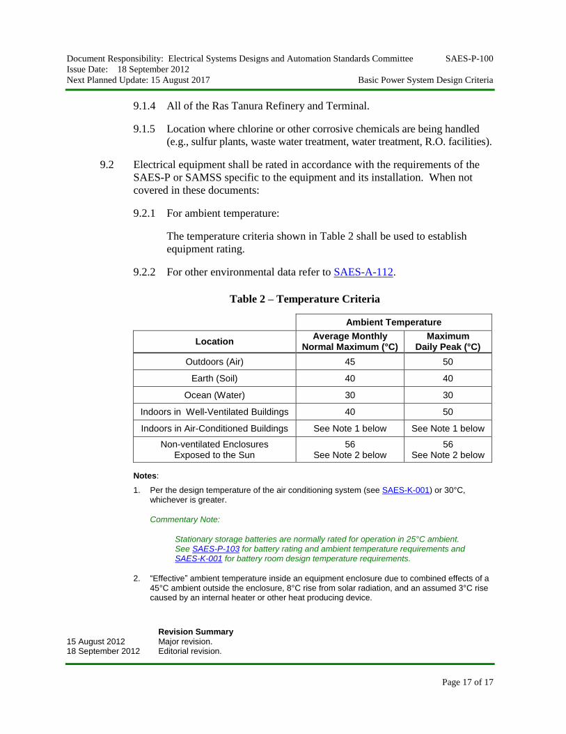
9.2.1 For ambient temperature:
The temperature criteria shown in Table 2 shall be used to establish
equipment rating.
9.2.2 For other environmental data refer to SAES-A-112.
Table 2 – Temperature Criteria
Ambient Temperature
Location Average Monthly
Normal Maximum (°C) Maximum
Daily Peak (°C)
Outdoors (Air) 45 50
Earth (Soil) 40 40
Ocean (Water) 30 30
Indoors in Well-Ventilated Buildings 40 50
Indoors in Air-Conditioned Buildings See Note 1 below See Note 1 below
Non-ventilated Enclosures Exposed to the Sun
56 See Note 2 below
56 See Note 2 below
Notes:
1. Per the design temperature of the air conditioning system (see SAES-K-001) or 30°C, whichever is greater.
Commentary Note:
Stationary storage batteries are normally rated for operation in 25°C ambient. See SAES-P-103 for battery rating and ambient temperature requirements and SAES-K-001 for battery room design temperature requirements.
2. “Effective” ambient temperature inside an equipment enclosure due to combined effects of a 45°C ambient outside the enclosure, 8°C rise from solar radiation, and an assumed 3°C rise caused by an internal heater or other heat producing device.
Revision Summary
15 August 2012 Major revision. 18 September 2012 Editorial revision.