Embed Size (px)
Citation preview

satspeed V7621-A1 User’s Manual
1
satspeed V7621-A1
VDSL2/ADSL2+ IAD
User’s Manual
satspeed V7621-A1 VDSL2/ADSL2+ IAD
satspeed V7621-A1 User’s Manual
2
Table of Contents
1 Introduction ................................................................................................................. 9
Features ................................................................................................................................................... 9
Device Requirements .............................................................................................................................. 9
Using this Document ............................................................................................................................. 10
Notational conventions ..................................................................................................................... 10
Typographical conventions .............................................................................................................. 10
Special messages ............................................................................................................................ 10
Getting Support ...................................................................................................................................... 10
2 Getting to know the device ....................................................................................... 11
Computer / System requirements ........................................................................................................ 11
Package Contents ................................................................................................................................. 11
For Annex-B Integrated Access Device .......................................................................................... 11
For Annex-A Integrated Access Device .......................................................................................... 11
Installation & Setup ................................................................................................................................ 12
LED meanings & activations ................................................................................................................. 14
Back Panel Connectors .................................................................................................................... 15
3 Computer configurations under different OS, to obtain IP address automatically ................................................................................................................ 16
4 Utility CD execution .................................................................................................. 27
Connecting the Hardware ..................................................................................................................... 27
VDSL WAN Configuration (VDSL Line User) ...................................................................................... 28
DSL WAN Configuration (ADSL Line User) ........................................................................................ 38
VoIP PHONE 1 Configuration .............................................................................................................. 49
VoIP PHONE 2 Configuration .............................................................................................................. 51
Wireless Configuration .......................................................................................................................... 53
Wireless Connection ............................................................................................................................. 58
5 USB 3G Configuration (This function may vary depending on model) ................... 60
Connecting the Hardware ..................................................................................................................... 60
USB 3G Configuration ........................................................................................................................... 61
Wireless Configuration .......................................................................................................................... 63
6 SAMBA- File Sharing with USB Host ....................................................................... 68
7 Getting Started with the Web pages ........................................................................ 70
Accessing the Web pages .................................................................................................................... 70
Testing your Setup ................................................................................................................................ 72
Default device settings .......................................................................................................................... 73
8 Overview ................................................................................................................... 75
Internet access settings ........................................................................................................................ 76
About Wireless VDSL2 Router ............................................................................................................. 76
9 Status ........................................................................................................................ 77
Device Info ............................................................................................................................................. 77
IPv6 ......................................................................................................................................................... 78

satspeed V7621-A1 User’s Manual
3
10 Local Network Configuration .................................................................................. 79
Changing the LAN IP address and subnet mask ................................................................................ 79
Adding the Secondary LAN IP address and subnet mask ................................................................. 81
Change IP Pool Range and Subnet mask........................................................................................... 82
11 Wireless Network .................................................................................................... 84
Basic Settings ........................................................................................................................................ 84
Advanced Settings ................................................................................................................................ 86
Security................................................................................................................................................... 89
WEP + Encryption Key ..................................................................................................................... 91
WEP + Use 802.1x Authentication .................................................................................................. 92
WPA/WPA2/WPA2 Mixed + Personal (Pre-Shared Key).............................................................. 93
WPA/WPA2/WPA2 Mixed + Enterprise (RADIUS) ........................................................................ 94
Access Control ....................................................................................................................................... 96
Allow Listed ....................................................................................................................................... 97
Deny Listed ....................................................................................................................................... 97
WPS ....................................................................................................................................................... 99
Introduction of WPS .......................................................................................................................... 99
Supported WPS features ................................................................................................................. 99
AP mode .......................................................................................................................................... 100
AP as Enrollee ................................................................................................................................ 100
AP as Registrar ............................................................................................................................... 100
AP as Proxy .................................................................................................................................... 100
Infrastructure-Client mode .............................................................................................................. 100
Instructions of AP’s and Client’s operations ................................................................................. 101
Operations of AP - AP being an enrollee ........................................................................................... 103
Operations of AP - AP being a registrar............................................................................................. 111
AP mode .......................................................................................................................................... 111
Push Button method ....................................................................................................................... 115
Wireless Multiple BSSID Settings ...................................................................................................... 119
Wireless Status .................................................................................................................................... 120
12 PTM WAN ............................................................................................................. 121
Configuring PTM WAN IPoE Static IP connection ............................................................................ 124
Configuring PTM WAN IPoE DHCP Client connection .................................................................... 128
Configuring PTM WAN PPPoE connection ....................................................................................... 129
Configuring PTM WAN DS-Lite connection ...................................................................................... 131
Configuring PTM WAN 6rd connection .............................................................................................. 132
13 ATM WAN ............................................................................................................. 134
Types of DSL WAN Internet Access .................................................................................................. 135
Configuring your PPPoE DSL connection ......................................................................................... 136
Configuring your PPPoA DSL connection ......................................................................................... 138
Configuring your Bridged DSL connection ........................................................................................ 140
Configuring your 1483 MER by DHCP .............................................................................................. 141
Configuring your 1483 MER by Fixed IP ........................................................................................... 142

satspeed V7621-A1 User’s Manual
4
ATM Settings ....................................................................................................................................... 144
DSL Settings ........................................................................................................................................ 146
14 3G Settings ........................................................................................................... 148
15 DHCP Settings ...................................................................................................... 150
DHCP Server Configuration ............................................................................................................... 150
DHCP Relay Configuration ................................................................................................................. 152
DHCP None Configuration.................................................................................................................. 153
16 DHCPv6 Settings .................................................................................................. 154
DHCP Server (Manual) Configuration ............................................................................................... 154
DHCP Server (Auto) Configuration .................................................................................................... 157
DHCP Relay Configuration ................................................................................................................. 158
DHCP None Configuration.................................................................................................................. 159
17 DNS Configuration ................................................................................................ 160
DHCP Server Configuration - Attain DNS Automatically .................................................................. 160
DHCP Server Configuration - Set DNS Manually ............................................................................. 161
18 Dynamic DNS Configuration ................................................................................ 163
Overview of Dynamic DNS ................................................................................................................. 163
Dynamic DNS Configuration – DynDNS.org ..................................................................................... 165
Dynamic DNS Configuration – TZO ................................................................................................... 166
19 IP/Port Filtering ..................................................................................................... 168
IP/Port Filtering .................................................................................................................................... 168
20 MAC Filtering ........................................................................................................ 170
Configuring MAC filtering to Deny for outgoing access .................................................................... 170
21 Port Forwarding .................................................................................................... 172
Port Forwarding for TCP with specified IP ......................................................................................... 174
Port Forwarding for UDP with specified IP ........................................................................................ 176
22 URL Blocking ........................................................................................................ 178
Configuring URL Blocking of FQDN ................................................................................................... 178
Configuring URL Blocking of Keyword ............................................................................................... 180
23 Domain Blocking ................................................................................................... 182
Configuring Domain Blocking ............................................................................................................. 182
24 DMZ ...................................................................................................................... 184
Configuring DMZ ................................................................................................................................. 184
25 UPnP ..................................................................................................................... 186
Configuring UPnP ................................................................................................................................ 187
UPnP Control Point Software on Windows ME................................................................................. 188
UPnP Control Point Software on Windows XP with Firewall ........................................................... 188
SSDP requirements ........................................................................................................................ 189
26 RIP ........................................................................................................................ 192
27 Samba ................................................................................................................... 194
Samba .................................................................................................................................................. 194
28 VoIP Configuration ............................................................................................... 195

satspeed V7621-A1 User’s Manual
5
Port 1/ Port 2 configurations ............................................................................................................... 201
SIP Account .................................................................................................................................... 207
SIP Advanced ................................................................................................................................. 209
Forward Mode ................................................................................................................................. 210
Speed Dial ....................................................................................................................................... 211
Abbreviated (Phonebook) Dial ....................................................................................................... 212
Dial plan ........................................................................................................................................... 214
PSTN Routing Prefix ...................................................................................................................... 214
Codec .............................................................................................................................................. 214
V.152 ............................................................................................................................................... 215
T.38(FAX) ........................................................................................................................................ 215
T.38(customize parameters) .......................................................................................................... 216
Hot Line ........................................................................................................................................... 216
DND (Don't Disturb) ........................................................................................................................ 217
Authentication ................................................................................................................................. 217
Alarm ............................................................................................................................................... 218
DSP ................................................................................................................................................. 219
Tone Settings ....................................................................................................................................... 223
Select Country ................................................................................................................................ 224
Select Custom Tone and Tone Parameters ................................................................................. 224
Ring Settings ........................................................................................................................................ 226
Other Settings ...................................................................................................................................... 227
Auto Provision Settings ....................................................................................................................... 228
Network Settings.................................................................................................................................. 229
29 ARP Table ............................................................................................................. 230
ARP Table ............................................................................................................................................ 230
30 Bridging ................................................................................................................. 231
Bridging ................................................................................................................................................ 231
31 Routing .................................................................................................................. 232
Static Route .......................................................................................................................................... 232
32 SNMP .................................................................................................................... 234
SNMP ................................................................................................................................................... 234
33 IP QoS ................................................................................................................... 236
QoS Policy ........................................................................................................................................... 236
QoS Classification ............................................................................................................................... 237
Traffic Shaping ..................................................................................................................................... 240
34 Remote Access .................................................................................................... 242
Remote Access ................................................................................................................................... 242
35 Others ................................................................................................................... 243
Others ................................................................................................................................................... 243
36 IPv6 ....................................................................................................................... 244

satspeed V7621-A1 User’s Manual
6
IPv6 ....................................................................................................................................................... 244
RADVD ................................................................................................................................................. 244
DHCPv6 ............................................................................................................................................... 245
MLD Proxy ........................................................................................................................................... 245
MLD Snooping ..................................................................................................................................... 246
IPv6 Routing ........................................................................................................................................ 247
IP/Port Filtering .................................................................................................................................... 248
37 Diagnostic ............................................................................................................. 249
Ping ....................................................................................................................................................... 249
ATM Loopback .................................................................................................................................... 250
DSL Tone Diagnostics ........................................................................................................................ 251
ADSL Connection Diagnostics ........................................................................................................... 252
38 Commit/Reboot ..................................................................................................... 253
Commit and Reboot ............................................................................................................................ 253
39 Backup/Restore .................................................................................................... 254
Backup settings ................................................................................................................................... 254
Restore settings ................................................................................................................................... 255
Resetting to Defaults ........................................................................................................................... 255
40 System Log ........................................................................................................... 257
System Log .......................................................................................................................................... 257
41 Password .............................................................................................................. 259
Setting your username and password ............................................................................................... 259
42 Firmware Update .................................................................................................. 261
About firmware versions ..................................................................................................................... 261
Manually updating firmware ................................................................................................................ 261
43 ACL Configuration ................................................................................................ 265
ACL Config ........................................................................................................................................... 265
44 Time Zone ............................................................................................................. 266
SNTP Server and SNTP Client Configuration settings ..................................................................... 266
45 TR-069 .................................................................................................................. 271
TR-069 Configuration .......................................................................................................................... 271
46 Statistics ................................................................................................................ 273
Statistics - Interface ............................................................................................................................. 273
Statistics - DSL .................................................................................................................................... 274
A Configuring your Computers .................................................................................. 275
Configuring Ethernet PCs ................................................................................................................... 275
Before you begin ............................................................................................................................. 275
Windows® XP PCs ......................................................................................................................... 275
Windows 2000 PCs ........................................................................................................................ 275
Windows Me PCs ........................................................................................................................... 277
Windows 95, 98 PCs ...................................................................................................................... 277
Windows NT 4.0 workstations ....................................................................................................... 278
Assigning static Internet information to your PCs ......................................................................... 279

satspeed V7621-A1 User’s Manual
7
B IP Addresses, Network Masks, and Subnets ........................................................ 280
IP Addresses ........................................................................................................................................ 280
Structure of an IP address ............................................................................................................. 280
Network classes .............................................................................................................................. 280
Subnet masks ...................................................................................................................................... 281
C Troubleshooting ..................................................................................................... 283
Troubleshooting Suggestions ............................................................................................................. 283
Diagnosing Problem using IP Utilities ................................................................................................ 285
ping .................................................................................................................................................. 285
nslookup .......................................................................................................................................... 286
D Glossary ................................................................................................................. 287

satspeed V7621-A1 User’s Manual
8

satspeed V7621-A1 User’s Manual
9
1 Introduction
Congratulations on becoming the owner of the Wireless VDSL2 Router. You will now be able to access the Internet using your high-speed DSL connection.
This User Guide will show you how to connect your Wireless VDSL2 Router, and how to customize its configuration to get the most out of your new product.
Features
The list below contains the main features of the device and may be useful to users with knowledge of networking protocols. If you are not an experienced user, the chapters throughout this guide will provide you with enough information to get the most out of your device.
Features include:
Internal DSL modem for high-speed Internet access
10/100Base-T Ethernet Router to provide Internet connectivity to all computers on your LAN
Network address translation (NAT) functions to provide security for your LAN
Network configuration through DHCP Server and DHCP Client
Services including IP route and DNS configuration, RIP, and IP and DSL performance monitoring
User-friendly configuration program accessed via a web browser
User-friendly configuration program accessed via EasySetup program
Device Requirements
In order to use the Wireless VDSL2 Router, you must have the following:
DSL service up and running on your telephone line
Instructions from your ISP on what type of Internet access you will be using, and the addresses needed to set up access
One or more computers each containing an Ethernet card (10Base-T/100Base-T network interface card (NIC))
For system configuration using the supplied a. web-based program: a web browser such as Internet Explorer, Google Chrome, Firefox, etc b. EasySetup program: Graphical User Interface
You do not need to use a hub or switch in order to connect more than one Ethernet PC to your device. Instead, you can connect

satspeed V7621-A1 User’s Manual
10
Note
up to four Ethernet PCs directly to your device using the ports labeled Ethernet on the rear panel.
Using this Document
Notational conventions
Acronyms are defined the first time they appear in the text and also in the glossary.
For brevity, the Wireless VDSL2 Router is referred to as “the device”.
The term LAN refers to a group of Ethernet-connected computers at one site.
Typographical conventions
Italic text is used for items you select from menus and drop-down lists and the names of displayed web pages.
Bold text is used for text strings that you type when prompted by the program, and to emphasize important points.
Special messages
This document uses the following icons to draw your attention to specific instructions or explanations.
Note
Provides clarifying or non-essential information on the current topic.
Definition
Explains terms or acronyms that may be unfamiliar to many readers. These terms are also included in the Glossary.
WARNING
Provides messages of high importance, including messages relating to personal safety or system integrity.
Getting Support
Supplied by: Helpdesk Number: Website:

satspeed V7621-A1 User’s Manual
11
2 Getting to know the device
Computer / System requirements
1. Pentium 200MHZ processor or above
2. Windows 98SE, Windows Me, Windows 2000, Windows XP, Windows Vista, Windows 7 and Windows 8
3. 64MB of RAM or above
4. 25MB free disk space
Package Contents
For Annex-B Integrated Access Device
1. Integrated Access Device
2. CD-ROM (Software & Manual)
3. Quick Installation Guide
4. 1 x Telephone Cable (RJ-11)
5. Ethernet Cable (RJ-45)
6. Power Adaptor
7. Annex-B Splitter (Optional, with an extra RJ-11 Telephone cable)
For Annex-A Integrated Access Device
1. Integrated Access Device
2. CD-ROM (Software & Manual)
3. Quick Installation Guide
4. 1 x Telephone Cable (RJ-11)
5. Ethernet Cable (RJ-45)
6. Power Adaptor
7. Annex-A Splitter (Optional, with an extra RJ-11 Telephone cable)

satspeed V7621-A1 User’s Manual
12
Installation & Setup
Follow each STEP carefully and only go to the next step once you have complete the previous STEP. Connection of Integrated Access Device
If you have an ISDN telephone line connect the modem router as shown below:
1. Connect the supplied RJ45 Ethernet cable from your PC's Ethernet port to any of the 4
Integrated Access Device's LAN Ports. 2. Connect the supplied RJ11 telephone cable from your home's telephone jack to the
“LINE” port of the supplied splitter. Connect another RJ11 telephone cable to the “MODEM” port of the splitter and connect the other end of this cable to the LINE port of your Integrated Access Device. (If there is no option Splitter, please connect the supplied RJ11 telephone cable from your home's telephone jack to the “LINE” port of your Integrated Access Device.)
3. Connect a RJ11 telephone cable to the “PHONE” port of the splitter and connect the other
end to your telephone. 4. Connect the power adapter to the power inlet “POWER” of the Integrated Access Device
and turn the “ON/OFF SWITCH” switch of your Integrated Access Device on.

satspeed V7621-A1 User’s Manual
13
If you have a PSTN telephone line (normal analog line) connect the router as shown below:
1. Connect the supplied RJ45 Ethernet cable from your PC's Ethernet port to any of the 4 Integrated Access Device's LAN Ports.
2. Connect the supplied RJ11 telephone cable from your home's telephone jack to the
“LINE” port of the supplied splitter. Connect the other supplied RJ11 telephone cable to the “DSL” port of the splitter and connect the other end of this cable to the “LINE” port of your Integrated Access Device. (If there is no option Splitter, please connect the supplied RJ11 telephone cable from your home's telephone jack to the “LINE” port of your Integrated Access Device.)
3. Connect a RJ11 telephone cable to the “PHONE” port of the splitter and connect the other
end to your telephone. 4. Connect the power adapter to the power inlet “POWER” of the Integrated Access Device
and turn the “ON/OFF SWITCH” switch of your Integrated Access Device on.

satspeed V7621-A1 User’s Manual
14
LED meanings & activations
Your Integrated Access Device has indicator lights on the front side. Please see below for an explanation of the function of each indicator light.
Power indicator
Internet Active indicator
Ethernet Active indicator
WPS Active indicator
Wireless Active indicator
DSL Link indicator
The phone is in use and VoIP link indicator
Table1. LED function
Label Color On Flash Off
Red N/A N/A N/A
Green Ready Waiting for device ready Power Off
Green Ethernet Connected Transmit / Receive Data
Ethernet Disconnected
Green WLAN Ready Transmit / Receive Data WLAN Off
Green Connect to DSLAM Disconnect to DSLAM N/A
Green The device has a WAN IP
address from ISP Transmit / Receive Data N/A
Red N/A N/A N/A
Green N/A
Start WPS peer within 2 minutes
WPS Idle
Green VoIP link established The phone is in use
No VoIP link established
The icons appear on the products are for application indication only.
The trademark or intellectual property is belonging to their respective owners.

satspeed V7621-A1 User’s Manual
15
Back Panel Connectors
Table 2 shows the function of each connector and switch of the device.
Table 2. Function / Description of Connectors
Connector Description
POWER Connects to your Integrated Access Device 12Vdc power adaptor
SWITCH Power Switch
LAN1~4 RJ-45 Jack (Ethernet Cable) connection to your PC, or HUB
PHONE 1 / PHONE 2
Connects the device to a regular telephone
LINE Connects to your VDSL2 line – for VDSL2 Line input
RESET Reset button. RESET the Integrated Access Device to its default settings. Press this button for at least 5 full seconds to start to reset it to its default settings.
WPS
Press this button for at least 3 full seconds and the WPS LED will flash to start WPS. Now go to the wireless adapter or device and press its WPS button. Make sure to press the button within 120 seconds (2 minutes) after pressing the router's WPS button.
WLAN Press this button for at least 3 full second to turn off/on wireless signals
USB Connect to a 3G Dongle or PEN Drive
Figure1. Rear View of the Integrated Access Device
Figure2. WPS and WLAN button

satspeed V7621-A1 User’s Manual
16
3 Computer configurations under different OS, to obtain IP address automatically
Before starting the Integrated Access Device configuration, please kindly configure the PC computer as below, to have automatic IP address / DNS Server.
For Windows 98SE / ME / 2000 / XP
1. Click on “Start” -> “Control Panel” (in Classic View). In the Control Panel, double click on “Network Connections” to continue.
2. Single RIGHT click on “Local Area connection”, then click “Properties”.

satspeed V7621-A1 User’s Manual
17
3. Double click on "Internet Protocol (TCP/ IP)".
4. Check "Obtain an IP address automatically" and “Obtain DNS server address automatically” then click on "OK" to continue.
5. Click "Show icon in notification area when connected" (see screen
image in 3. above) then Click on "OK" to complete the setup procedures.

satspeed V7621-A1 User’s Manual
18
For Windows Vista-32/64 1. Click on “Start” -> “Control Panel” -> “View network status and tasks”.
2. In the Manage network connections, click on “Manage network connections” to continue.

satspeed V7621-A1 User’s Manual
19
3. Single RIGHT click on “Local Area connection", then click "Properties".
4. The screen will display the information “User Account Control” and click “Continue” to continue.
5. Double click on "Internet Protocol Version 4 (TCP/IPv4)".

satspeed V7621-A1 User’s Manual
20
6. Check "Obtain an IP address automatically" and “Obtain DNS server address automatically” then click on "OK" to continue.
For Windows 7-32/64 1. Click on “Start” -> “Control Panel” (in Category View) -> “View network
status and tasks”.

satspeed V7621-A1 User’s Manual
21
2. In the Control Panel Home, click on “Change adapter settings” to continue.
3. Single RIGHT click on “Local Area connection", then click "Properties".

satspeed V7621-A1 User’s Manual
22
4. Double click on "Internet Protocol Version 4 (TCP/IPv4)".
5. Check "Obtain an IP address automatically" and “Obtain DNS server address automatically” then click on "OK" to continue.

satspeed V7621-A1 User’s Manual
23
For Windows 8-32/64 1. Move the mouse or tap to the upper right corner and click on “Settings”.
2. Click on “Control Panel”.

satspeed V7621-A1 User’s Manual
24
3. Click on “View network status and tasks”.
4. In the Control Panel Home, click on “Change adapter settings” to continue.

satspeed V7621-A1 User’s Manual
25
5. Single RIGHT click on “Ethernet", then click "Properties".
6. Double click on "Internet Protocol Version 4 (TCP/IPv4)".

satspeed V7621-A1 User’s Manual
26
7. Check "Obtain an IP address automatically" and “Obtain DNS server address automatically” then click on "OK" to continue.

satspeed V7621-A1 User’s Manual
27
4 Utility CD execution
Connecting the Hardware
This section describes how to connect the device to the wall phone port, the power outlet and your computer(s) or network.
1. Before you begin to execute utility CD Installations, please ensure the Integrated Access Device has been powered on.
2. Please insert the supplied CD into your CD-ROM drive.
3. The CD should auto-start, displaying the window shown in 4. below. If your CD does not start automatically, go to Windows Explorer, Select your CD drive and double click "Autorun.exe".
4. To configure the Internet and Wireless configuration, please click the " Advanced Configuration ".
satspeed V7621-A1 User’s Manual
28
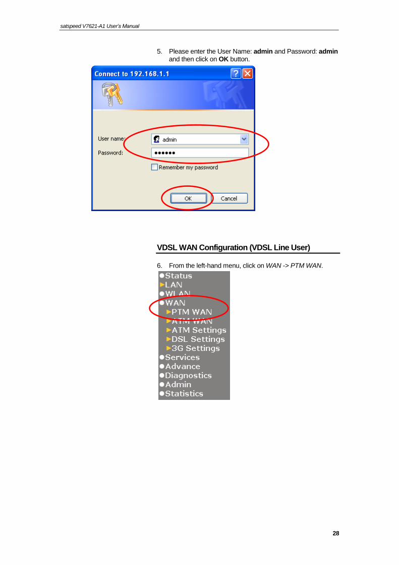
5. Please enter the User Name: admin and Password: admin and then click on OK button.
VDSL WAN Configuration (VDSL Line User)
6. From the left-hand menu, click on WAN -> PTM WAN.

satspeed V7621-A1 User’s Manual
29
Examples
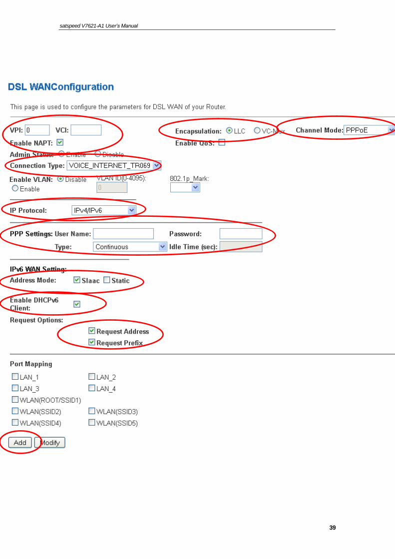
8-1. PPPoE
From the Channel Mode drop-down list, select PPPoE setting.
Enable Enable NAPT
From the Connection Type drop-down list, select VOICE_INTERNET_TR069 setting.
From the IP Protocol drop-down list, select the IP Protocol, IPv4, IPv6 or dual stacks IPv4/IPv6 determined by your ISP.
Enter User Name/Password provided by your ISP. Type them in the relevant boxes.
Configure IPv6 WAN setting determined by your ISP if any.
If you are happy with your settings, click Apply Changes

satspeed V7621-A1 User’s Manual
30

satspeed V7621-A1 User’s Manual
31
8-2. Bridged
From the Channel Mode drop-down list, select Bridged setting.
From the Connection Type drop-down list, select VOICE_INTERNET_TR069 setting.
If you are happy with your settings, click Apply Changes
Now you can load your PPPoE Client Software onto your PC.
Now you can load your PPPoE Client Software with user name and password which determined by your ISP onto your PC.

satspeed V7621-A1 User’s Manual
32
8-3. IPoE by DHCP
From the Channel Mode drop-down list, select IPoE
Enable Enable NAPT
From the Connection Type drop-down list, select VOICE_INTERNET_TR069 setting.
From the IP Protocol drop-down list, select the IP Protocol, IPv4, IPv6 or dual stacks IPv4/IPv6 determined by your ISP.
From the Type ratio, click DHCP.
Configure IPv6 WAN setting determined by your ISP if any.
If you are happy with your settings, click Apply Changes

satspeed V7621-A1 User’s Manual
33

satspeed V7621-A1 User’s Manual
34
8-4. IPoE by Fixed IP
From the Channel Mode drop-down list, select IPoE setting.
Enable Enable NAPT
From the Connection Type drop-down list, select VOICE_INTERNET_TR069 setting.
From the IP Protocol drop-down list, select the IP Protocol, IPv4, IPv6 or dual stacks IPv4/IPv6 determined by your ISP.
From the Type ratio, click Fixed IP.
Enter Local IP Address, Subnet Mask and Remote IP Address which was given by Telecom or by your Internet Service Provider (ISP).
Configure IPv6 WAN setting determined by your ISP if any.
If you are happy with your settings, click Apply Changes

satspeed V7621-A1 User’s Manual
35

satspeed V7621-A1 User’s Manual
36
From the left-hand Service menu, click on Services -> DHCP.
From the Type ratio, click Set Manually.
Enter DNS setting determined by your ISP.
If you are happy with your settings, click Apply Changes

satspeed V7621-A1 User’s Manual
37
Click OK
7. From the left-hand menu, click on Admin -> Commit/Reboot.
8. Click on Commit and Reboot.
9. Click on OK.

satspeed V7621-A1 User’s Manual
38
10. System rebooting, Please wait ...
DSL WAN Configuration (ADSL Line User)
11. From the left-hand menu, click on WAN -> ATM WAN.
Examples
8-1. PPPoE
Enter VCI and VPI setting determined by your ISP.
Select the Encapsulation determined by your ISP.
From the Channel Mode drop-down list, select PPPoE setting.
Enable Enable NAPT
From the Connection Type drop-down list, select VOICE_INTERNET_TR069 setting.
From the IP Protocol drop-down list, select the IP Protocol, IPv4, IPv6 or dual stacks IPv4/IPv6 determined by your ISP.
Enter User Name/Password provided by your ISP. Type them in the relevant boxes.
Configure IPv6 WAN setting determined by your ISP if any.
If you are happy with your settings, click Add
satspeed V7621-A1 User’s Manual
39

satspeed V7621-A1 User’s Manual
40
8-2. PPPoA
Enter VCI and VPI setting determined by your ISP.
Select the Encapsulation determined by your ISP.
From the Channel Mode drop-down list, select PPPoA setting.
Enable Enable NAPT
From the Connection Type drop-down list, select VOICE_INTERNET_TR069 setting.
From the IP Protocol drop-down list, select the IP Protocol, IPv4, IPv6 or dual stacks IPv4/IPv6 determined by your ISP.
Enter User Name/Password provided by your ISP. Type them in the relevant boxes.
Configure IPv6 WAN setting determined by your ISP if any.
If you are happy with your settings, click Add

satspeed V7621-A1 User’s Manual
41

satspeed V7621-A1 User’s Manual
42
8-3. Bridged
Enter VCI and VPI setting determined by your ISP.
Select the Encapsulation determined by your ISP.
From the Channel Mode drop-down list, select 1483 Bridged setting.
From the Connection Type drop-down list, select VOICE_INTERNET_TR069 setting.
If you are happy with your settings, click Add
Now you can load your PPPoE Client Software onto your PC.
Now you can load your PPPoE Client Software with user name and password which determined by your ISP onto your PC.

satspeed V7621-A1 User’s Manual
43
8-4. 1483 MER by DHCP
Enter VCI and VPI setting determined by your ISP.
Select the Encapsulation determined by your ISP.
From the Channel Mode drop-down list, select 1483 MER
Enable Enable NAPT
From the Connection Type drop-down list, select VOICE_INTERNET_TR069 setting.
From the IP Protocol drop-down list, select the IP Protocol, IPv4, IPv6 or dual stacks IPv4/IPv6 determined by your ISP.
From the Type ratio, click DHCP.
Configure IPv6 WAN setting determined by your ISP if any.
If you are happy with your settings, click Add

satspeed V7621-A1 User’s Manual
44

satspeed V7621-A1 User’s Manual
45
8-5. 1483 MER by Fixed IP
Enter VCI and VPI setting determined by your ISP.
Select the Encapsulation determined by your ISP.
Enable Enable NAPT
From the Connection Type drop-down list, select VOICE_INTERNET_TR069 setting.
From the Channel Mode drop-down list, select 1483 MER setting.
From the IP Protocol drop-down list, select the IP Protocol, IPv4, IPv6 or dual stacks IPv4/IPv6 determined by your ISP.
From the Type ratio, click Fixed IP.
Enter Local IP Address, Subnet Mask and Remote IP Address which was given by Telecom or by your Internet Service Provider (ISP).
Configure IPv6 WAN setting determined by your ISP.
If you are happy with your settings, click Add

satspeed V7621-A1 User’s Manual
46

satspeed V7621-A1 User’s Manual
47
From the left-hand Service menu, click on Services -> DHCP.
From the Type ratio, click Set Manually.
Enter DNS setting determined by your ISP.
If you are happy with your settings, click Apply Changes

satspeed V7621-A1 User’s Manual
48
Click OK
12. From the left-hand menu, click on Admin -> Commit/Reboot.
13. Click on Commit and Reboot.
14. Click on OK.

satspeed V7621-A1 User’s Manual
49
15. System rebooting, Please wait ...
VoIP PHONE 1 Configuration
16. From the left-hand menu, click on VoIP -> Port1.

satspeed V7621-A1 User’s Manual
50
17. Enter Display Name, Number, Login ID and Password.
18. Enable Proxy.
19. Enter Proxy Server Address and Proxy Server Port of SIP Server for example 192.168.10.101 and 5060.
20. Enter SIP Domain Address of SIP Server for example 192.168.10.101.
21. Enable Outbound Proxy.
22. Enter Outbound Proxy Address and Outbound Proxy Port of SIP Server for example 192.168.10.101 and 5060.
23. Click " Apply " button.

satspeed V7621-A1 User’s Manual
51
VoIP PHONE 2 Configuration
24. From the left-hand menu, click on VoIP -> Port2.

satspeed V7621-A1 User’s Manual
52
25. Enter Display Name, Number, Login ID and Password.
26. Enable Proxy.
27. Enter Proxy Server Address and Proxy Server Port of SIP Server for example 192.168.10.101 and 5060.
28. Enter SIP Domain Address of SIP Server for example 192.168.10.101.
29. Enable Outbound Proxy.
30. Enter Outbound Proxy Address and Outbound Proxy Port of SIP Server for example 192.168.10.101 and 5060.
31. Click " Apply " button.

satspeed V7621-A1 User’s Manual
53
Wireless Configuration
32. From the left-hand menu, click on WLAN -> Basic Settings.

satspeed V7621-A1 User’s Manual
54
33. From the Band drop-down list, select a Band.
34. From the Mode drop-down list, select AP setting.
35. Enter SSID for example VDSL-8673. (the default settings Radio On/Off = On, Network Name(SSID) = IAD-xxxx which could be found on the sticker of the bottom side of the device).
36. From the Channel Width drop-down list, select a Channel Width.
37. From the Control Sideband drop-down list, select a Control Sideband.
38. From the Channel Number drop-down list, select a Channel Number.
39. Click Apply Changes.
40. Change setting successfully!
41. Click OK.

satspeed V7621-A1 User’s Manual
55
42. From the left-hand menu, click on WLAN -> Security.
43. From the Encryption list, choose the Encryption type if necessary, as None / WEP / WPA / WPA2 and WPA2 Mixed Mode (the default settings Security Mode = WPA2 and passphrase is xxxxxxxx which could be found on the sticker of the bottom side of the device). For example, the Encryption you choose is None.
44. Click Apply Changes.
45. Warning : security is not set! This may be dangerous!
46. Click OK.

satspeed V7621-A1 User’s Manual
56
47. Change setting successfully!
48. Click OK.
49. From the left-hand menu, click on Admin -> Commit/Reboot.
50. Click on Commit and Reboot.
51. Click on OK.

satspeed V7621-A1 User’s Manual
57
52. System rebooting, Please wait ...
53. Click on " Exit " to exit this program.
54. Now, the Integrated Access Device has been configured completely, and suitable for Wireless and Internet Connections.

satspeed V7621-A1 User’s Manual
58
Wireless Connection
For easy installation it is saved to keep the settings. You can later change the wireless settings via the wireless configuration menu. (see user manual on the CD – Chapter 11 and other).
55. Double click on the wireless icon on your computer and search for the wireless network that you enter SSID name.
56. Click on the wireless network that you enter SSID name (the default setting SSID = IAD-xxxx) to connect.

satspeed V7621-A1 User’s Manual
59
57. If the wireless network isn’t encrypted, click on "Connect Anyway" to connect.
58. If the wireless network is encrypted, enter the network key that belongs to your authentication type and key. (the default settings Security Mode = Disable). You can later change this network key via the wireless configuration menu. (see user manual on the CD – Chapter 11 and other).
59. Click on "Connect" or "Apply".
60. Now you are ready to use the Wireless Network to Internet or intranet.

satspeed V7621-A1 User’s Manual
60
5 USB 3G Configuration (This function may vary depending on model)
Connecting the Hardware
This section describes how to connect the device to the wall phone port, the power outlet and your computer(s) or network.
WARNING
Before you begin, turn the power off for all devices. These include your computer(s), your LAN hub/switch (if applicable), and the Wireless Gateway.
The diagram below illustrates the hardware connections. The layout of the ports on your device may vary from the layout shown. Refer to the steps that follow for specific instructions.
Step 1. Connect the 3G USB Modem to USB Port
Connect the 3G USB Modem to 802.11n WLAN Router's USB Port.
Step 2. Connect the Ethernet cable to LAN Port
Connect the supplied RJ45 Ethernet cable from your PC's Ethernet port to any of the 4 802.11n WLAN Router's LAN Ports.
Step 3. Attach the power connector
Connect the power adapter to the power inlet “POWER” of the 802.11n WLAN Router and turn the power switch “ON/OFF SWITCH” of your 802.11n WLAN Router on.
* Actual ANTENNA may vary depending on model

satspeed V7621-A1 User’s Manual
61
USB 3G Configuration
61. Visit web page http://192.168.1.1 and then enter the Login User Name: admin and Login Password: admin and then click on OK button.
62. From the left-hand menu, click on WAN -> 3G Settings.
satspeed V7621-A1 User’s Manual
62
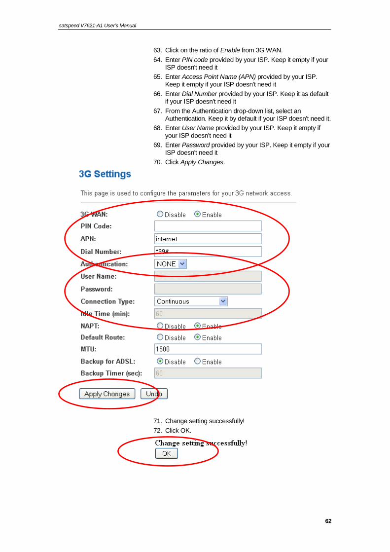
63. Click on the ratio of Enable from 3G WAN.
64. Enter PIN code provided by your ISP. Keep it empty if your ISP doesn't need it
65. Enter Access Point Name (APN) provided by your ISP. Keep it empty if your ISP doesn't need it
66. Enter Dial Number provided by your ISP. Keep it as default if your ISP doesn't need it
67. From the Authentication drop-down list, select an Authentication. Keep it by default if your ISP doesn't need it.
68. Enter User Name provided by your ISP. Keep it empty if your ISP doesn't need it
69. Enter Password provided by your ISP. Keep it empty if your ISP doesn't need it
70. Click Apply Changes.
71. Change setting successfully!
72. Click OK.

satspeed V7621-A1 User’s Manual
63
Wireless Configuration
73. From the left-hand menu, click on WLAN -> Basic Settings.

satspeed V7621-A1 User’s Manual
64
74. From the Band drop-down list, select a Band.
75. From the Mode drop-down list, select AP setting.
76. Enter SSID for example VDSL-8673. (the default settings Radio On/Off = On, Network Name(SSID) = IAD-xxxx which could be found on the sticker of the bottom side of the device).
77. From the Channel Width drop-down list, select a Channel Width.
78. From the Control Sideband drop-down list, select a Control Sideband.
79. From the Channel Number drop-down list, select a Channel Number.
80. Click Apply Changes.
81. Change setting successfully!
82. Click OK.

satspeed V7621-A1 User’s Manual
65
83. From the left-hand menu, click on WLAN -> Security.
84. From the Encryption list, choose the Encryption type if necessary, as None / WEP / WPA / WPA2 and WPA2 Mixed Mode (the default settings Security Mode = WPA2 and passphrase is xxxxxxxx which could be found on the sticker of the bottom side of the device). For example, the Encryption you choose is None.
85. Click Apply Changes.
86. Warning: security is not set! This may be dangerous!
87. Click OK.

satspeed V7621-A1 User’s Manual
66
88. Change setting successfully!
89. Click OK.
90. From the left-hand menu, click on Admin -> Commit/Reboot.
91. Click on Commit and Reboot.
92. Click on OK.

satspeed V7621-A1 User’s Manual
67
93. System rebooting, Please wait ...
94. Now you are ready to use the USB 3G to Internet.

satspeed V7621-A1 User’s Manual
68
6 SAMBA- File Sharing with USB Host
The device includes a USB Host let you sharing, read and write files on PEN Drive.
You can have read and write access for FAT16/FAT32 format of PEN Drive.
You can have only read access for NTFS format of PEN Drive.
95. Connect the PEN Drive into the USB Host.
96. Click on Start Menu -> My Computer.
.

satspeed V7621-A1 User’s Manual
69
97. Fill in \\192.168.1.1\mnt\sda1 in Address field and then press Enter key. You will see the Samba Server below.
98. You can access the PEN Drive for reading and or writing files now.

satspeed V7621-A1 User’s Manual
70
7 Getting Started with the Web pages
The Wireless VDSL2 Router includes a series of Web pages that provide an interface to the software installed on the device. It enables you to configure the device settings to meet the needs of your network. You can access it through your web browser from any PC connected to the device via the LAN ports.
Accessing the Web pages
To access the Web pages, you need the following:
A PC or laptop connected to the LAN port on the device.
For the best display quality, use latest version of Internet Explorer, Chrome, Firefox.From any of the LAN computers, launch your web browser, type the following URL in the web address (or location) box, and press [Enter] on your keyboard:
http://192.168.1.1
The Status homepage for the web pages is displayed:

satspeed V7621-A1 User’s Manual
71
Figure 1: Homepage
The first time that you click on an entry from the left-hand menu, a login box is displayed. You must enter your username and password to access the pages.
A login screen is displayed:

satspeed V7621-A1 User’s Manual
72
Figure 2: Login screen
99. Enter your user name and password. The first time you log into the program, use these defaults:
User Name: admin
Password: admin
Note
You can change the password at any time or you can configure your device so that you do not need to enter a password. See Password.
100. Click on OK. You are now ready to configure your device.
This is the first page displayed each time you log in to the Web pages. This page contains links to the following pages:
Addressing; links to the Addressing page that controls your device’s network address. See Addressing.
Internet Access; links to the Internet Access page that controls how your device connects to the Internet. See Internet Access.
Note
If you receive an error message or the Welcome page is not displayed, see Troubleshooting Suggestions.
Testing your Setup
Once you have connected your hardware and configured your PCs, any computer on your LAN should be able to use the device’s DSL connection to access the Internet.
To test the connection, turn on the device, wait for 30 seconds and then verify that the LEDs are illuminated as follows:

satspeed V7621-A1 User’s Manual
73
Table 1. LED Indicators
LED Behavior
POWER Solid green to indicate that the device is turned on. If this light is not on, check the power cable attachment.
ETH Flashing on/off while the device is booting. After about 10-15 seconds, solid green to indicate that the device can communicate with your LAN.
Link Flashing on/off while data is being transmitted. Solid green to indicate that the device has successfully established a connection with your ISP.
INTERNET Flashing on/off while data is being transferred. Solid green when a valid IP address has been assigned to the device by the ISP.
If the LEDs illuminate as expected, test your Internet connection from a LAN computer. To do this, open your web browser, and type the URL of any external website (such as http://www.yahoo.com). The LED labeled INTERNET should blink rapidly and then appear solid as the device connects to the site.
If the LEDs do not illuminate as expected, you may need to configure your Internet access settings using the information provided by your ISP. For details, see Internet Access. If the LEDs still do not illuminate as expected or the web page is not displayed, see Troubleshooting Suggestions or contact your ISP for assistance.
Default device settings
In addition to handling the DSL connection to your ISP, the DSL Modem can provide a variety of services to your network. The device is preconfigured with default settings for use with a typical home or small office network.
The table below lists some of the most important default settings; these and other features are described fully in the subsequent chapters. If you are familiar with network configuration, review these settings to verify that they meet the needs of your network. Follow the instructions to change them if necessary. If you are unfamiliar with these settings, try using the device without modification, or contact your ISP for assistance.
WARNING
We strongly recommend that you contact your ISP prior to changing the default configuration.
Option Default Setting Explanation/Instructions
LINE Port IP Address
Unnumbered interface:
192.168.1.1
Subnet mask:
255.255.255.255
This is the temporary public IP address of the WAN port on the device. It is an unnumbered interface that is replaced as soon as your ISP assigns a ‘real’ IP address. See Internet Access.

satspeed V7621-A1 User’s Manual
74
Option Default Setting Explanation/Instructions
LAN Port IP Address
Assigned static IP address: 192.168.1.1
Subnet mask: 255.255.255.0
This is the IP address of the LAN port on the device. The LAN port connects the device to your Ethernet network. Typically, you will not need to change this address. See LAN.
DHCP (Dynamic Host Configuration Protocol)
DHCP server enabled with the following pool of addresses:
192.168.1.33 through 192.168.1.254
The Wireless VDSL2 Router maintains a pool of private IP addresses for dynamic assignment to your LAN computers. To use this service, you must have set up your computers to accept IP information dynamically, as described in Services -> DHCP Settings.
NAT (Network Address Translation)
NAT enabled Your computers’ private IP addresses (see DHCP above) will be translated to your public IP address whenever the PCs access the Internet. See Services -> Firewall.

Satspeed V7621-A1 User’s Manual Configuring your Computers
75
8 Overview
The Overview page displays useful information about the setup of your device, including:
details of the device’s Internet access settings
version information about your device
To display this page:
From the left menu, click on Status - Device. The following page is displayed:
Figure 3: Overview page
The information displayed on this page is explained in detail in the following sections.

Satspeed V7621-A1 User’s Manual Configuring your Computers
76
Internet access settings
This section displays details of the settings that allow your device to access the Internet. These details include:
IP address and subnet mask:
The IP address and subnet mask assigned to your WAN interface. This address is used temporarily until your ISP assigns a real IP address (via DHCP or PPP – see Internet Access.
Default gateway: The address of the ISP server through which your Internet connection will be routed.
DNS servers: The Domain Name System (DNS) servers used by your ISP to map domain names to IP addresses.
Your ISP assigns all of these settings. In most cases, you will not need to make changes to these settings in order for your Internet connection to work. If your ISP does ask you to change any of these settings, follow the instructions for manually configuring your device in Internet Access.
About Wireless VDSL2 Router
This section displays details of your device’s hardware and firmware versions. If you need to contact your ISP’s support team, they may need to know which hardware/firmware versions you are using in order to answer your query.
Your hardware version details contain information about the make and model of your device and its exact hardware components.
Your firmware version details contain information about the software program running on your device. They then make the latest updated version available to you via the Internet. For details of how to update your firmware, see Admin -> Upgrade Firmware.

Satspeed V7621-A1 User’s Manual Configuring your Computers
77
9 Status
You can view statistics on the processing of IP packets on the networking interfaces. You will not typically need to view this data, but you may find it helpful when working with your ISP to diagnose network and Internet data transmission problems.
Device Info
This page shows the current status and some basic settings of the device.
101. From the left Status menu, click on Device. The following page is displayed:
102. To display updated statistics showing any new data since you opened this page, click Refresh.
Satspeed V7621-A1 User’s Manual Configuring your Computers
78
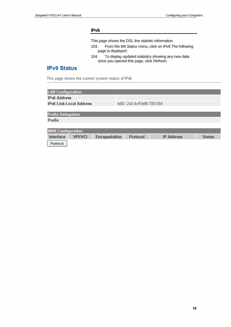
IPv6
This page shows the DSL line statistic information.
103. From the left Status menu, click on IPv6 The following page is displayed:
104. To display updated statistics showing any new data since you opened this page, click Refresh.

Satspeed V7621-A1 User’s Manual Configuring your Computers
79
10 Local Network Configuration
The Addressing page displays information about your LAN IP address and allows you to change the address and subnet mask assigned to your device.
Note
You should only change the addressing details if your ISP asks you to, or if you are familiar with network configuration. In most cases, you will not need to make any changes to this configuration.
Changing the LAN IP address and subnet mask
105. From the left menu, click on LAN. The following page is displayed:

Satspeed V7621-A1 User’s Manual Configuring your Computers
80
106. From the left-hand LAN menu, click on LAN.
107. Type a new IP Address and Subnet Mask.
108. Click Apply Changes.
109. The primary IP address is being changed to 10.0.0.2 netmask 255.255.255.0. Then please go to http://10.0.0.2 to continue. Your browser communicates with the web server via the LAN connection, and changing the IP address may disrupt this.
You may also need to renew your DHCP lease:
Windows 95/98
a. Select Run... from the Start menu.
b. Enter winipcfg and click OK.
c. Select your ethernet adaptor from the pull-down menu
d. Click Release All and then Renew All.
e. Exit the winipcfg dialog.
Windows NT/Windows 2000/Windows XP
a. Bring up a command window.
b. Type ipconfig /release in the command window.
c. Type ipconfig /renew.
d. Type exit to close the command window.
Linux
a. Bring up a shell.
b. Type pump -r to release the lease.
c. Type pump to renew the lease.

Satspeed V7621-A1 User’s Manual Configuring your Computers
81
Note
If you change the LAN IP address of the device while connected through your Web browser, you will be disconnected. You must open a new connection by entering your new LAN IP address as the URL.
Adding the Secondary LAN IP address and subnet mask
110. From the left-hand LAN menu, click on LAN.
111. Check on Secondary IP.
112. Type the Secondary IP Address and Subnet Mask.
113. Click Apply Changes.
114. Change setting successfully!
115. Click OK.

Satspeed V7621-A1 User’s Manual Configuring your Computers
82
Change IP Pool Range and Subnet mask
116. From the left-hand Services menu, click on DHCP.

Satspeed V7621-A1 User’s Manual Configuring your Computers
83
117. Change the IP Pool Range/Subnet Mask and then click Apply Changes button.
118. Change setting successfully!
119. Click OK.

Satspeed V7621-A1 User’s Manual Configuring your Computers
84
11 Wireless Network
This chapter assumes that you have already set up your Wireless PCs and installed a compatible Wireless card on your device. See Configuring Wireless PCs.
Basic Settings
This page contains all of the wireless basic settings. Most users will be able to configure the wireless portion and get it working properly using the setting on this screen.
The Wireless Network page allows you to configure the Wireless features of your device. To access the Wireless Network Basic Settings page:
From the left WLAN menu, click on Basic Settings. The following page is displayed:
Figure 4: Wireless Network page
Satspeed V7621-A1 User’s Manual Configuring your Computers
85
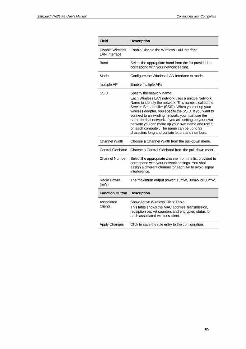
Field Description
Disable Wireless LAN Interface
Enable/Disable the Wireless LAN Interface.
Band Select the appropriate band from the list provided to correspond with your network setting.
Mode Configure the Wireless LAN Interface to mode
multiple AP Enable multiple APs
SSID Specify the network name.
Each Wireless LAN network uses a unique Network Name to identify the network. This name is called the Service Set Identifier (SSID). When you set up your wireless adapter, you specify the SSID. If you want to connect to an existing network, you must use the name for that network. If you are setting up your own network you can make up your own name and use it on each computer. The name can be up to 32 characters long and contain letters and numbers.
Channel Width Choose a Channel Width from the pull-down menu.
Control Sideband Choose a Control Sideband from the pull-down menu.
Channel Number Select the appropriate channel from the list provided to correspond with your network settings. You shall assign a different channel for each AP to avoid signal interference.
Radio Power (mW)
The maximum output power: 15mW, 30mW or 60mW.
Function Button Description
Associated Clients
Show Active Wireless Client Table
This table shows the MAC address, transmission, receiption packet counters and encrypted status for each associated wireless client.
Apply Changes Click to save the rule entry to the configuration.

Satspeed V7621-A1 User’s Manual Configuring your Computers
86
Advanced Settings
These settings are only for more technically advanced users who have a sufficient knowledge about wireless LAN. These settings should not be changed unless you know what effect the changes will have on your Access Point. To access the Wireless Network Advanced Settings page:
120. From the left-hand WLAN menu, click on Advanced. The following page is displayed:
Satspeed V7621-A1 User’s Manual Configuring your Computers
87
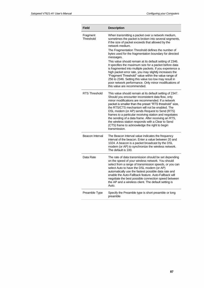
Field Description
Fragment Threshold
When transmitting a packet over a network medium, sometimes the packet is broken into several segments, if the size of packet exceeds that allowed by the network medium.
The Fragmentation Threshold defines the number of bytes used for the fragmentation boundary for directed messages.
This value should remain at its default setting of 2346. It specifies the maximum size for a packet before data is fragmented into multiple packets. If you experience a high packet error rate, you may slightly increases the “Fragment Threshold” value within the value range of 256 to 2346. Setting this value too low may result in poor network performance. Only minor modifications of this value are recommended.
RTS Threshold This value should remain at its default setting of 2347. Should you encounter inconsistent data flow, only minor modifications are recommended. If a network packet is smaller than the preset “RTS threshold” size, the RTS/CTS mechanism will not be enabled. The DSL modem (or AP) sends Request to Send (RTS) frames to a particular receiving station and negotiates the sending of a data frame. After receiving an RTS, the wireless station responds with a Clear to Send (CTS) frame to acknowledge the right to begin transmission.
Beacon Interval The Beacon Interval value indicates the frequency interval of the beacon. Enter a value between 20 and 1024. A beacon is a packet broadcast by the DSL modem (or AP) to synchronize the wireless network. The default is 100.
Data Rate The rate of data transmission should be set depending on the speed of your wireless network. You should select from a range of transmission speeds, or you can select Auto to have the DSL modem (or AP) automatically use the fastest possible data rate and enable the Auto-Fallback feature. Auto-Fallback will negotiate the best possible connection speed between the AP and a wireless client. The default setting is Auto.
Preamble Type Specify the Preamble type is short preamble or long preamble

Satspeed V7621-A1 User’s Manual Configuring your Computers
88
Field Description
Broadcast SSID Broadcast or Hide SSID to your Network.
Default: Enabled
Relay Blocking Disable or Enable Relay Blocking
Protection A protection mechanism prevents collisions among 802.11g nodes.
Aggregation Disable or Enable Aggregation
Short GI Disable or Enable Short GI
WMM Support Enable/disable the Wi-Fi Multimedia (WMM) support.
Function Button Description
Apply Changes Click to save the rule entry to the configuration.

Satspeed V7621-A1 User’s Manual Configuring your Computers
89
Security
This page allows you setup the wireless security. Turn on WEP or WPA by using Encryption Keys could prevent any unauthorized access to your wireless network. To access the Wireless Network Security page:
From the left-hand WLAN menu, click on Security. The following page is displayed:
Satspeed V7621-A1 User’s Manual Configuring your Computers
90
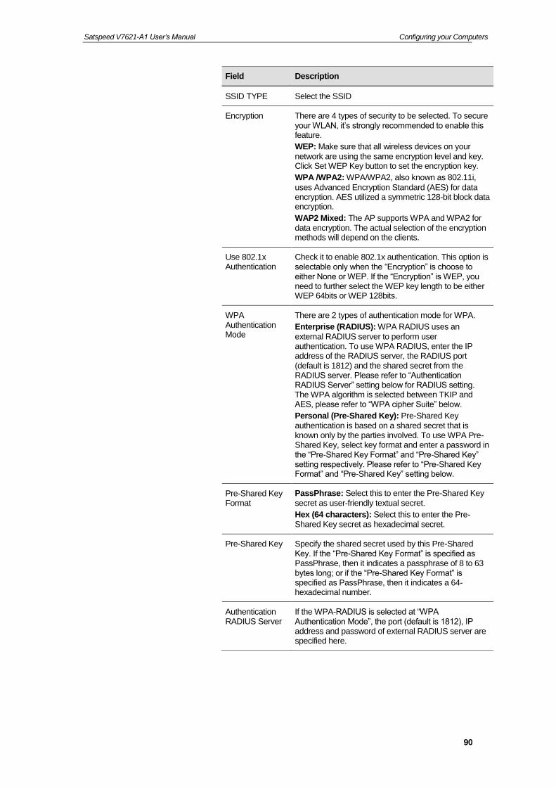
Field Description
SSID TYPE Select the SSID
Encryption There are 4 types of security to be selected. To secure your WLAN, it’s strongly recommended to enable this feature.
WEP: Make sure that all wireless devices on your
network are using the same encryption level and key. Click Set WEP Key button to set the encryption key.
WPA /WPA2: WPA/WPA2, also known as 802.11i,
uses Advanced Encryption Standard (AES) for data encryption. AES utilized a symmetric 128-bit block data encryption.
WAP2 Mixed: The AP supports WPA and WPA2 for
data encryption. The actual selection of the encryption methods will depend on the clients.
Use 802.1x Authentication
Check it to enable 802.1x authentication. This option is selectable only when the “Encryption” is choose to either None or WEP. If the “Encryption” is WEP, you need to further select the WEP key length to be either WEP 64bits or WEP 128bits.
WPA Authentication Mode
There are 2 types of authentication mode for WPA.
Enterprise (RADIUS): WPA RADIUS uses an
external RADIUS server to perform user authentication. To use WPA RADIUS, enter the IP address of the RADIUS server, the RADIUS port (default is 1812) and the shared secret from the RADIUS server. Please refer to “Authentication RADIUS Server” setting below for RADIUS setting. The WPA algorithm is selected between TKIP and AES, please refer to “WPA cipher Suite” below.
Personal (Pre-Shared Key): Pre-Shared Key
authentication is based on a shared secret that is known only by the parties involved. To use WPA Pre-Shared Key, select key format and enter a password in the “Pre-Shared Key Format” and “Pre-Shared Key” setting respectively. Please refer to “Pre-Shared Key Format” and “Pre-Shared Key” setting below.
Pre-Shared Key Format
PassPhrase: Select this to enter the Pre-Shared Key
secret as user-friendly textual secret.
Hex (64 characters): Select this to enter the Pre-Shared Key secret as hexadecimal secret.
Pre-Shared Key Specify the shared secret used by this Pre-Shared Key. If the “Pre-Shared Key Format” is specified as PassPhrase, then it indicates a passphrase of 8 to 63 bytes long; or if the “Pre-Shared Key Format” is specified as PassPhrase, then it indicates a 64-hexadecimal number.
Authentication RADIUS Server
If the WPA-RADIUS is selected at “WPA Authentication Mode”, the port (default is 1812), IP address and password of external RADIUS server are specified here.

Satspeed V7621-A1 User’s Manual Configuring your Computers
91
WEP + Encryption Key
WEP aims to provide security by encrypting data over radio waves so that it is protected as it is transmitted from one end point to another. However, it has been found that WEP is not as secure as once believed.
121. From the Encryption drop-down list, select WEP setting.
122. From the Key Length drop-down list, select 64-bit or 128-bit setting.
123. From the Key Format drop-down list, select ASCII (5 characters), Hex (10 characters), ASCII (13 characters) or Hex (26 characters) setting.
124. Enter the Encryption Key value depending on selected ASCII or Hexadecimal.
125. Click Apply Changes button.
126. Click OK button.
Function Button Description
Apply Changes Click to save the rule entry to the configuration.

Satspeed V7621-A1 User’s Manual Configuring your Computers
92
127. Change setting successfully!
128. Click OK.
WEP + Use 802.1x Authentication
WEP aims to provide security by encrypting data over radio waves so that it is protected as it is transmitted from one end point to another. However, it has been found that WEP is not as secure as once believed.
129. From the Encryption drop-down list, select WEP setting.
130. Check the option of Use 802.1x Authentication.
131. Click on the ratio of WEP 64bits or WEP 128bits.
132. Enter the Port, IP Address and Password of RADIUS Server.
133. Click Apply Changes button.
134. Click OK button.

Satspeed V7621-A1 User’s Manual Configuring your Computers
93
135. Change setting successfully!
136. Click OK.
WPA/WPA2/WPA2 Mixed + Personal (Pre-Shared Key)
Wi-Fi Protected Access (WPA) is a class of systems to secure wireless (Wi-Fi) computer networks. WPA/WPA2 implements the full standard, but will not work with some older network cards. Both provide good security, with two significant issues:
WPA/WPA2 must be enabled and chosen in preference to WEP. WEP is usually presented as the first security choice in most installation instructions.
In the "Personal" mode, the most likely choice for homes and small offices, a pass phrase is required that, for full security, must be longer than the typical 6 to 8 character passwords users are taught to employ.
137. From the Encryption drop-down list, select WPA, WPA2 or WPA2 Mixed setting.
138. Click on the ratio of Personal (Pre-Shared Key).
139. Check on the WPA Cipher Suite.
140. From the Pre-Shared Key Format drop-down list, select Passphrase or Hex (64 characters) setting.

Satspeed V7621-A1 User’s Manual Configuring your Computers
94
141. Enter the Pre-Shared Key depending on selected Passphrase or Hex (64 characters).
142. Click on Apply Changes button to confirm.
143. Click OK button.
144. Change setting successfully!
145. Click OK.
WPA/WPA2/WPA2 Mixed + Enterprise (RADIUS)
Wi-Fi Protected Access (WPA) is a class of systems to secure wireless (Wi-Fi) computer networks. WPA/WPA2 implements the full standard, but will not work with some older network cards. Both provide good security, with two significant issues:
WPA/WPA2 must be enabled and chosen in preference to WEP. WEP is usually presented as the first security choice in most installation instructions.
In the "Personal" mode, the most likely choice for homes and small offices, a pass phrase is required that, for full security, must be longer than the typical 6 to 8 character passwords users are taught to employ.
146. From the Encryption drop-down list, select WPA, WPA2 or WPA2 Mixed setting.
147. Click on the ratio of Enterprise (RADIUS).

Satspeed V7621-A1 User’s Manual Configuring your Computers
95
148. Check on the WPA Cipher Suite.
149. Enter the Port, IP Address and Password of RADIUS Server).
150. Click on Apply Changes button to confirm.
151. Click OK button.
152. Change setting successfully!
153. Click OK.
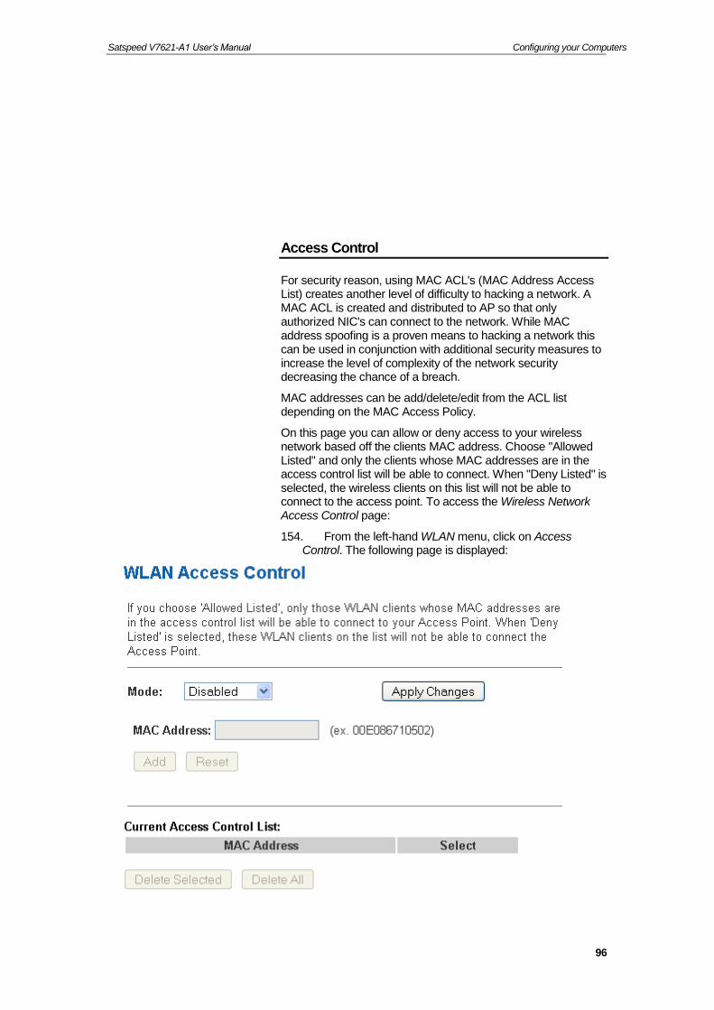
Satspeed V7621-A1 User’s Manual Configuring your Computers
96
Access Control
For security reason, using MAC ACL's (MAC Address Access List) creates another level of difficulty to hacking a network. A MAC ACL is created and distributed to AP so that only authorized NIC's can connect to the network. While MAC address spoofing is a proven means to hacking a network this can be used in conjunction with additional security measures to increase the level of complexity of the network security decreasing the chance of a breach.
MAC addresses can be add/delete/edit from the ACL list depending on the MAC Access Policy.
On this page you can allow or deny access to your wireless network based off the clients MAC address. Choose "Allowed Listed" and only the clients whose MAC addresses are in the access control list will be able to connect. When "Deny Listed" is selected, the wireless clients on this list will not be able to connect to the access point. To access the Wireless Network Access Control page:
154. From the left-hand WLAN menu, click on Access Control. The following page is displayed:

Satspeed V7621-A1 User’s Manual Configuring your Computers
97
Allow Listed
If you choose 'Allowed Listed', only those clients whose wireless MAC addresses are in the access control list will be able to connect to your Access Point.
155. From the Mode drop-down list, select Allowed Listed setting.
156. Change setting successfully!
157. Click OK.
158. Enter the MAC Address.
159. Click Add button.
160. Change setting successfully!
161. Click OK.
162. The MAC Address that you created has been added in the Current Access Control List.
Deny Listed
When 'Deny Listed' is selected, these wireless clients on the list will not be able to connect the Access Point.
163. From the Mode drop-down list, select Deny Listed setting.
164. Change setting successfully!

Satspeed V7621-A1 User’s Manual Configuring your Computers
98
165. Click OK.
166. Enter the MAC Address.
167. Click Add button.
168. Change setting successfully!
169. Click OK.
170. The MAC Address that you created has been added in the Current Access Control List.

Satspeed V7621-A1 User’s Manual Configuring your Computers
99
WPS
Introduction of WPS
Although home Wi-Fi networks have become more and more popular, users still have trouble with the initial set up of network. This obstacle forces users to use the open security and increases the risk of eavesdropping. Therefore, WPS is designed to ease set up of security-enabled Wi-Fi networks and subsequently network management (Wi-Fi Protected Setup Specification 1.0h.pdf, p. 8).
The largest difference between WPS-enabled devices and legacy devices is that users do not need the knowledge about SSID, channel and security settings, but they could still surf in a security-enabled Wi-Fi network. For examples, in the initial network set up, if users want to use the PIN configuration, the only thing they need to do is entering the device PIN into registrar, starting the PIN method on that device and simply wait until the device joins the network. After the PIN method is started on both sides, a registration protocol will be initiated between the registrar and the enrollee. Typically, a registrar could be an access point or other device that is capable of managing the network. An enrollee could be an access point or a station that will join the network. After the registration protocol has been done, the enrollee will receive SSID and security settings from the registrar and then join the network. In other words; if a station attempts to join a network managed by an access point with built-in internal registrar, users will need to enter station’s PIN into the web page of that access point. If the device PIN is correct and valid and users start PIN on station, the access point and the station will automatically exchange the encrypted information of the network settings under the management of AP’s internal registrar. The station then uses this information to perform authentication algorithm, join the secure network, and transmit data with the encryption algorithm. More details will be demonstrated in the following sections.
Supported WPS features
Currently, Wireless Gateway supports WPS features for AP mode, AP+WDS mode, Infrastructure-Client mode, and the wireless root interface of Universal Repeater mode.
Other modes such as WDS mode, Infrastructure-Adhoc mode, and the wireless virtual interface of Universal Repeater mode are not implemented with WPS features.
If those unsupported modes are enforced by users, WPS will be disabled. Under the configuration of every WPS-supported mode, Wireless Gateway has Push Button method and PIN method. For each method, Wireless Gateway offers different security levels included in network credential, such as

Satspeed V7621-A1 User’s Manual Configuring your Computers
100
open security, WEP 64 bits, WEP 128 bits, WPA2-Personal TKIP, and WPA2-Personal AES. Users could choose either one of the methods at their convenience.
AP mode
For AP mode, Wireless Gateway supports three roles, registrar, proxy, and enrollee in registration protocol. At different scenarios, Wireless Gateway will automatically switch to an appropriate role depending on the other device’s role or a specific configuration.
AP as Enrollee
If users know AP’s PIN and enter it into external registrar, the external registrar will configure AP with a new wireless profile such as new SSID and new security settings. The external registrar does this job either utilizing the in-band EAP (wireless) or out-of-band UPnP (Ethernet). During the WPS handshake, a wireless profile is encrypted and transmitted to AP. If the handshake is successfully done, AP will be re-initialized with the new wireless profile and wait for legacy stations or WPS stations to join its network.
AP as Registrar
Wireless Gateway also has a built-in internal registrar. Whenever users enter station’s PIN into AP’s webpage, click “Start PBC”, or push the physical button, AP will switch to registrar automatically. If users apply the same method on station side and the WPS handshake is successfully done, SSID and security settings will be transmitted to that station without the risk of eavesdropping. And then the station will associate with AP in a security-enabled network.
AP as Proxy
At this state, AP is transparent to users. If users want to configure a station or any device that is capable of being an enrollee, they have to enter device’s PIN into an external registrar and choose an appropriate wireless profile. After the PIN is entered, the external registrar will inform AP this event. AP then conveys the encrypted wireless profile between the device and the external registrar. Finally, the device will use the wireless profile and associate with AP. However, the device may connect to other APs if the wireless profile does not belong to the proxy AP. Users must carefully choose the wireless profile or create a wireless profile on an external registrar.
Infrastructure-Client mode
In Infrastructure-Client mode, Wireless Gateway only supports enrollee’s role. If users click “Start PIN”, click “Start PBC”, or press the physical button on Wireless Gateway, it will start to seek WPS AP. Once users apply the same method on registrar side, Wireless Gateway will receive the wireless profile upon

Satspeed V7621-A1 User’s Manual Configuring your Computers
101
successfully doing the registration protocol. Then Wireless Gateway will associate with an AP.
Instructions of AP’s and Client’s operations
At this state, AP is transparent to users. If users want to configure a station or any device that is capable of being an enrollee, they have to enter device’s PIN into an external registrar and choose an appropriate wireless profile. After the PIN is entered, the external registrar will inform AP this event. AP then conveys the encrypted wireless profile between the device and the external registrar. Finally, the device will use the wireless profile and associate with AP. However, the device may connect to other APs if the wireless profile does not belong to the proxy AP. Users must carefully choose the wireless profile or create a wireless profile on an external registrar.
This device supports Push Button method and PIN method for WPS. The following sub-paragraphs will describe the function of each item. The webpage is as below. To access the Wireless Network WPS page:
From the left-hand WLAN menu, click on WPS. The following page is displayed:

Satspeed V7621-A1 User’s Manual Configuring your Computers
102
Field Description
Disable WPS Check to disable the Wi-Fi protected Setup.
WPS Status When AP’s settings are factory default (out of box), it is set to open security and un-configured state. “WPS Status” will display it as “UnConfigured”. If it already shows “Configured”, some registrars such as Vista WCN will not configure AP. Users will need to go to the “Backup/Restore” page and click “Reset” to reload factory default settings.
Self-PIN Number “Self-PIN Number” is AP’s PIN. Whenever users want to change AP’s PIN, they could click “Regenerate PIN” and then click “ Apply Changes”. Moreover, if users want to make their own PIN, they could enter four-digit PIN without checksum and then click “ Apply Changes”. However, this would not be recommended since the registrar side needs to be supported with four-digit PIN.
Push Button Configuration
“Self-PIN Number” is AP’s PIN. Whenever users want to change AP’s PIN, they could click “Regenerate PIN” and then click “ Apply Changes”. Moreover, if users want to make their own PIN, they could enter four-digit PIN without checksum and then click “ Apply Changes”. However, this would not be recommended since the registrar side needs to be supported with four-digit PIN.
Push Button Configuration
Clicking this button will invoke the PBC method of WPS. It is only used when AP acts as a registrar.
Client PIN Number
It is only used when users want their station to join AP’s network. The length of PIN is limited to four or eight numeric digits. If users enter eight-digit PIN with checksum error, there will be a warning message popping up. If users insist on this PIN, AP will take it.
Function Button Description
Regenerate PIN Click to regenerate the Self-PIN Number.
Start PBC Click to start the Push Button method of WPS.
Apply Changes Click to commit changes.
Reset It restores the original values.
Start PIN Click to start the PIN method of WPS.

Satspeed V7621-A1 User’s Manual Configuring your Computers
103
Operations of AP - AP being an enrollee
In this case, AP will be configured by any registrar either through in-band EAP or UPnP. Here, users do not need to do any action on AP side. They just need AP’s device PIN and enter it into registrar. An example from Vista WCN will be given.
171. From the left-hand WLAN -> WPS menu. The following page is displayed:
172. Make sure AP is in un-configured state.
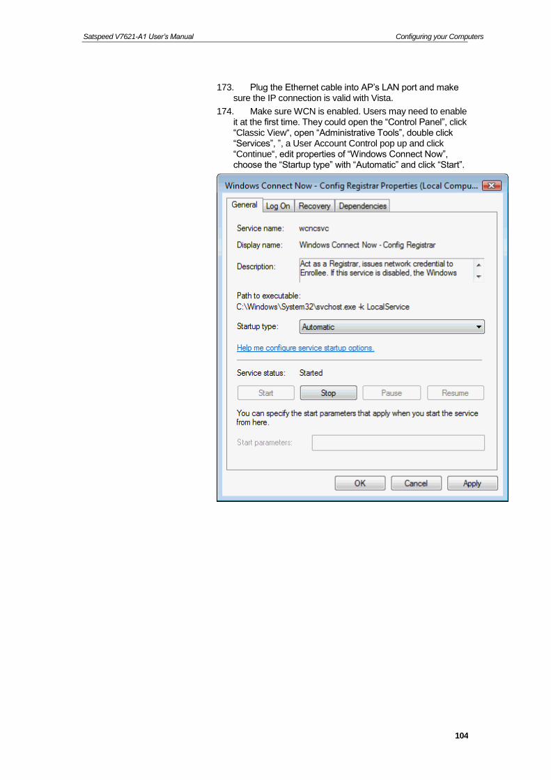
Satspeed V7621-A1 User’s Manual Configuring your Computers
104
173. Plug the Ethernet cable into AP’s LAN port and make sure the IP connection is valid with Vista.
174. Make sure WCN is enabled. Users may need to enable it at the first time. They could open the “Control Panel”, click “Classic View“, open “Administrative Tools”, double click “Services”, ”, a User Account Control pop up and click “Continue“, edit properties of “Windows Connect Now”, choose the “Startup type” with “Automatic” and click “Start”.

Satspeed V7621-A1 User’s Manual Configuring your Computers
105
175. If the previous steps are done, open Windows Explorer. Go to the Network section.
176. Click on “Network discovery and file sharing are turned off. Network computers and devices are not visible. Click to Change…“

Satspeed V7621-A1 User’s Manual Configuring your Computers
106
177. Click on “Turn on network discovery and file sharing“
178. Click on “No, make the network that I am connected to a private network“

Satspeed V7621-A1 User’s Manual Configuring your Computers
107
179. AP’s icon will show up. Double click on it.
180. Users could also Click “Add a wireless device” if the icon is not there. Click “next”.

Satspeed V7621-A1 User’s Manual Configuring your Computers
108
181. Enter AP’s Self-PIN Number and click “next”.
182. Choose a name that people who connect to your network will recognize.
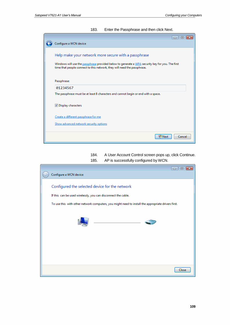
Satspeed V7621-A1 User’s Manual Configuring your Computers
109
183. Enter the Passphrase and then click Next.
184. A User Account Control screen pops up, click Continue.
185. AP is successfully configured by WCN.

Satspeed V7621-A1 User’s Manual Configuring your Computers
110
186. Finally, AP will become configured (see WPS Status). The authentication algorithm, encryption algorithm, and key assigned by WCN will be displayed below “Current Key Info”.
187. The SSID field of Wireless Basic Settings page will also be modified with the value assigned by WCN.

Satspeed V7621-A1 User’s Manual Configuring your Computers
111
Operations of AP - AP being a registrar
AP mode
Whenever users enter station’s PIN into AP’s Wi-Fi Protected Setup page and click “Start PIN”, AP will become a registrar. Users must start the PIN method on the station side within two minutes.
188. From the left-hand WLAN -> WPS menu. The following page is displayed:
189. Make sure AP is in un-configured state.
190. Enter the Client PIN Number.
191. Click Start PIN.
192. Users must start the PIN method on the station side within two minutes.
193. Users must start the PIN method on the station side within two minutes.

Satspeed V7621-A1 User’s Manual Configuring your Computers
112

Satspeed V7621-A1 User’s Manual Configuring your Computers
113
194. If the device PIN is correct and the WPS handshake is successfully done on the station side, User’s Wi-Fi Protected status will be shown as below.

Satspeed V7621-A1 User’s Manual Configuring your Computers
114
195. If the device PIN is correct and the WPS handshake is successfully done, AP’s Wi-Fi Protected Setup page will be shown as below.
Other pages such as Wireless Basic Settings page and Wireless Security Setup page will also be updated appropriately as described in previous sections. In this case, AP is in un-configured state before the station initiates the WPS handshake. According to the WPS spec, AP will create a wireless profile with WPA2-mixed mode and a random-generated key upon successfully doing the WPS handshake. However, AP will use the original wireless profile and give it to the station if AP is already in configured state. That means all settings of AP will not change. Hence, all WPS related pages keep the same.

Satspeed V7621-A1 User’s Manual Configuring your Computers
115
Push Button method
Wireless Gateway supports a virtual button “Start PBC” on the Wi-Fi Protected Setup page for Push Button method. If users push a virtual button “Start PBC”, AP will initiate a WPS session and wait for any station to join. At this moment, AP will detect whether there is more than one station that starts the PBC method. When multiple PBC sessions occur, users should try PIN method.
After users push AP’s virtual button “Start PBC”, they must go to station side to push its button within two minutes. If the WPS is successfully done, AP will give its wireless profile to that station. The station could use this profile to associate with AP.
196. From the left-hand WLAN -> WPS menu. The following page is displayed:
197. Make sure AP is in un-configured state.
198. Click Start PBC.
199. Users must start the PBC method on the station side within two minutes.

Satspeed V7621-A1 User’s Manual Configuring your Computers
116
200. Users must start the PBC method on the station side within two minutes.

Satspeed V7621-A1 User’s Manual Configuring your Computers
117
201. If the device PCB and the WPS handshake is successfully done on the station side, User’s Wi-Fi Protected status will be shown as below.

Satspeed V7621-A1 User’s Manual Configuring your Computers
118
202. If the device PIN is correct and the WPS handshake is successfully done, AP’s Wi-Fi Protected Setup page will be shown as below.
Other pages such as Wireless Basic Settings page and Wireless Security Setup page will also be updated appropriately as described in previous sections. In this case, AP is in un-configured state before the station initiates the WPS handshake. According to the WPS spec, AP will create a wireless profile with WPA2-mixed mode and a random-generated key upon successfully doing the WPS handshake. However, AP will use the original wireless profile and give it to the station if AP is already in configured state. That means all settings of AP will not change. Hence, all WPS related pages keep the same.

Satspeed V7621-A1 User’s Manual Configuring your Computers
119
Wireless Multiple BSSID Settings
This page allows you to set Virtual Access Points (VAP). Here you can enable/disable virtual APs and set the SSID and authentication type. Click "Apply Changes" for these settings to take effect.
To access the MBSSID Settings page:
203. From the left-hand WLAN menu, click on Basic Settings - Multiple AP. The following page is displayed:

Satspeed V7621-A1 User’s Manual Configuring your Computers
120
Wireless Status
This page shows the WLAN current status.
To access the Wireless Status page:
204. From the left-hand WLAN menu, click on Status The following page is displayed:

Satspeed V7621-A1 User’s Manual Configuring your Computers
121
12 PTM WAN
This chapter describes how to configure the way that your device connects to the Internet. Your ISP determines what type of Internet access you should use and provides you with any information that you need in order to configure the Internet access to your device.
The device supports four methods of obtaining the WAN IP address:
Option Description
Bridged Choose this option to have the device to be a AP
IPoE Fixed IP
Choose this option if you are a leased line user with a fixed IP address.
IpoE DHCP Client
Choose this option if you are connected to the Internet through a Cable modem line.
PPPoE Choose this option if you are connected to the Internet through a DSL line
DS-Lite Choose this option if you are connected to the DS-Lite Server
6rd Choose this option if you are connected to the 6rd Server
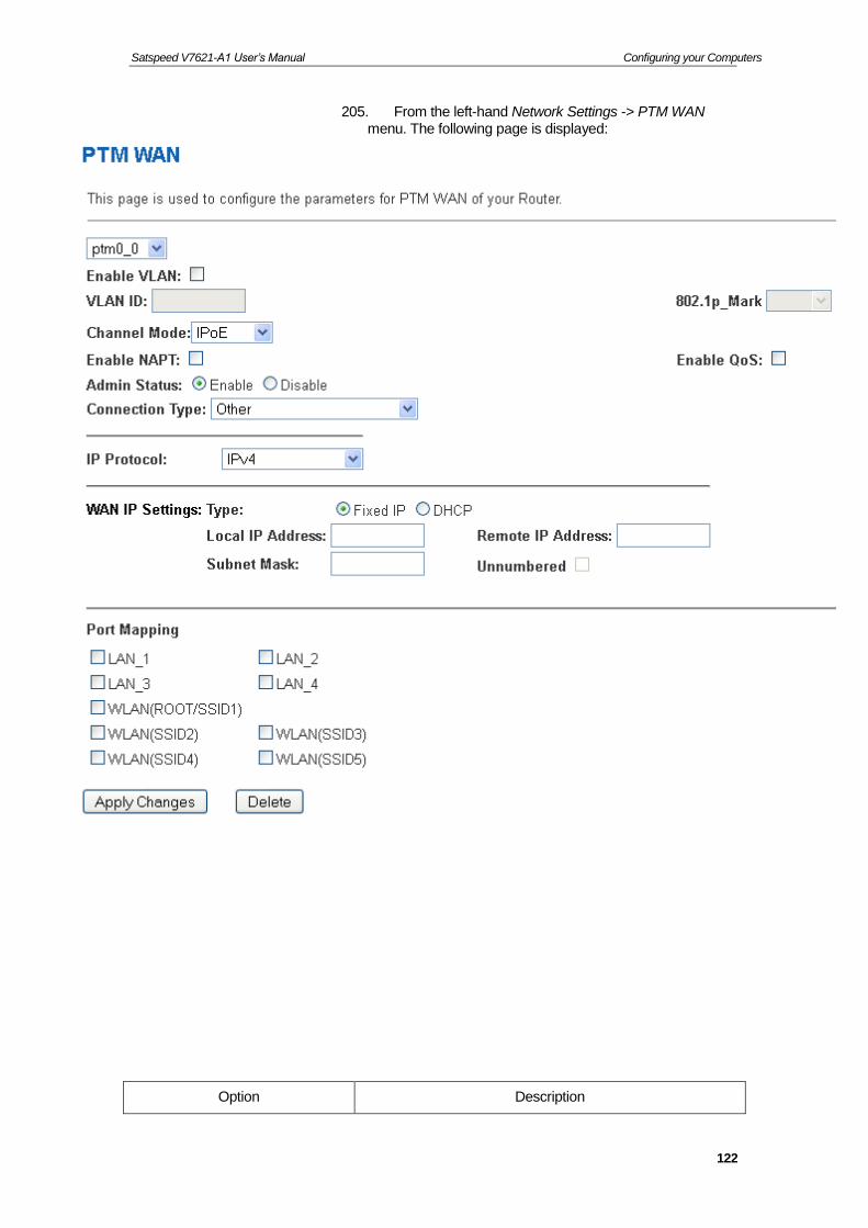
Satspeed V7621-A1 User’s Manual Configuring your Computers
122
205. From the left-hand Network Settings -> PTM WAN menu. The following page is displayed:
Option Description

Satspeed V7621-A1 User’s Manual Configuring your Computers
123
Enable VLAN Enable or disable VLAN
VLAN ID Enter the VLAN ID
802.1p_Mark Choose the 802.1p_Mark
Channel Mode
Bridged Choose this option to have the device to be a AP
IPoE Fixed IP Choose this option if you are a leased line user with a fixed IP address.
IPoE DHCP Client Choose this option if you are connected to the Internet through a Cable modem line.
PPPoE Choose this option if you are connected to the Internet through a DSL modem line
DS-Lite Choose this option if you are connected to the DS-Lite Server
6rd Choose this option if you are connected to the 6rd Server
Enable NAPT Enable or disable NAPT
Enable IGMP Enable or disable IGMP
Enable Default Route Enable or disable Default Route
Enable Admin Status Enable or disable Admin Status
IP Protocol IPv4/IPv6, IPv4 or IPv6
Local IP Address Check with your ISP provider
Subnet Mask Check with your ISP provider
Remote IP Address Check with your ISP provider
User Name User name for PPPoE registration recognized by the Internet service provider
Password Password for PPPoE registration recognized by the Internet service provider
Connection Type
Continuous The connection is always on
Connect on Demand
Enter the minutes after which the session must be disconnected, if no activity takes place
Manual Manually connect
Idle Time Enter the minutes after which the session must be disconnected
IPv6 WAN Address Mode Check with your ISP provider
Enable DHCPv6 Client Check with your ISP provider
Port Mapping Port Mapping configuration

Satspeed V7621-A1 User’s Manual Configuring your Computers
124
Configuring PTM WAN IPoE Static IP connection
If you are a leased line user with a fixed IP address, enter in the IP address, subnet mask, gateway address, and DNS (domain name server) address(es) provided to you by your ISP.
If your ISP wants you to connect to the Internet using Static IP, follow the instructions below.
206. From the left-hand WAN Settings -> PTM WAN menu. The following page is displayed:
207. From the Channel Mode drop-down list, select IPoE setting.
208. Enable Enable NAPT
209. Select proper Connection Type
210. Enable Fixed IP
211. Enter Local IP Address, WAN Subnet Mask and Remote IP Address which was given by Telecom or by your Internet Service Provider (ISP).
212. Click Apply Changes.

Satspeed V7621-A1 User’s Manual Configuring your Computers
125

Satspeed V7621-A1 User’s Manual Configuring your Computers
126
213. From the left-hand menu, click on Services -> DHCP.

Satspeed V7621-A1 User’s Manual Configuring your Computers
127
214. From the Type ratio, click Set Manually.
215. Enter DNS setting determined by your ISP.
216. If you are happy with your settings, click Apply Changes
217. Click OK.

Satspeed V7621-A1 User’s Manual Configuring your Computers
128
Configuring PTM WAN IPoE DHCP Client connection
Dynamic Host Configuration Protocol (DHCP), Dynamic IP (Get WAN IP Address automatically). If you are connected to the Internet through a Cable modem line, then a dynamic IP will be assigned.
If your ISP wants you to connect to the Internet using DHCP Client, follow the instructions below.
218. From the left-hand WAN Settings -> PTM WAN menu. The following page is displayed:
219. From the Channel Mode drop-down list, select IPoE setting.
220. Enable Enable NAPT
221. Select proper Connection Type
222. Enable DHCP
223. Click Apply Changes.

Satspeed V7621-A1 User’s Manual Configuring your Computers
129
Configuring PTM WAN PPPoE connection
If your ISP’s Internet service uses PPPoE you need to set up a PPP login account. The first time that you login to the Internet, your ISP will ask you to enter a username and password so they can check that you are a legitimate, registered Internet service user. Your device stores these authentication details, so you will not have to enter this username and password every time you login.
If your ISP wants you to connect to the Internet using PPP, follow the instructions below.
224. From the left-hand WAN Settings -> PTM WAN menu. The following page is displayed:
225. From the Channel Mode drop-down list, select PPPoE setting.
226. Enable Enable NAPT
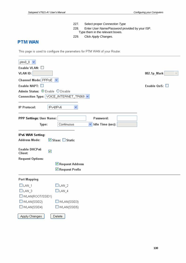
Satspeed V7621-A1 User’s Manual Configuring your Computers
130
227. Select proper Connection Type
228. Enter User Name/Password provided by your ISP. Type them in the relevant boxes.
229. Click Apply Changes.

Satspeed V7621-A1 User’s Manual Configuring your Computers
131
Configuring PTM WAN DS-Lite connection
If you are a leased line with DS-Lite user with a fixed IP address, enter in the IP address, subnet mask, gateway address, and DNS (domain name server) address(es) provided to you by your ISP.
If your ISP wants you to connect to the Internet using DS-Lite, follow the instructions below.
230. From the left-hand WAN Settings -> PTM WAN menu. The following page is displayed:
231. From the Channel Mode drop-down list, select DS-Lite setting.
232. Enable Enable NAPT
233. Select proper Connection Type
234. Enter Local IPv6 Address, Remote IPv6 End point Address and Gateway IPv6 Address which was given by Telecom or by your Internet Service Provider (ISP).
235. Click Apply Changes.

Satspeed V7621-A1 User’s Manual Configuring your Computers
132
Configuring PTM WAN 6rd connection
If you are a leased line with 6rd user with a fixed IP address, enter in the IP address, subnet mask, gateway address, and DNS (domain name server) address(es) provided to you by your ISP.
If your ISP wants you to connect to the Internet using 6rd, follow the instructions below.
236. From the left-hand WAN Settings -> PTM WAN menu. The following page is displayed:
237. From the Channel Mode drop-down list, select 6rd setting.
238. Enable Enable NAPT
239. Select proper Connection Type
240. Enter Board Router v4 Address, 6rd IPv4 Mask Len, 6rd Prefix (EX:"2001:db8::") and 6rd Prefix length which was given by Telecom or by your Internet Service Provider (ISP).
241. Click Apply Changes.
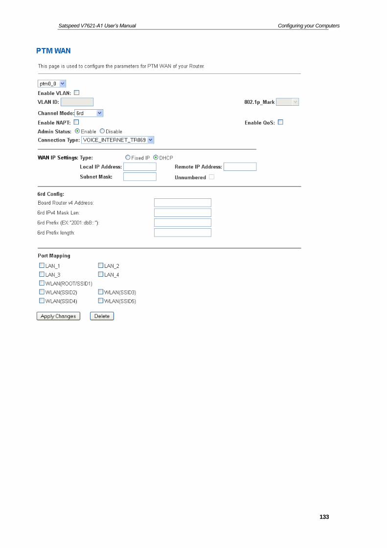
Satspeed V7621-A1 User’s Manual Configuring your Computers
133

Satspeed V7621-A1 User’s Manual Configuring your Computers
134
13 ATM WAN
This chapter describes how to configure the way that your device connects to the Internet. Your ISP determines what type of Internet access you should use and provides you with any information that you need in order to configure the Internet access to your device.
Your device needs the following address information in order to access the Internet:
ATM PVC To configure ATM PVC, enter the VPI and VCI provided by ISP. Select the Service Type Index, Service Category and enter the following information:
Peak Cell Rate
Sustainable Cell Rate
Maximum Burst Size
Channel Mode To configure the connection type, select the protocol and encapsulation type as indicated by ISP. Supported Protocol types are:
RFC1483 Bridged
RFC1483 MER
PPPoE
PPPoA
RFC1483 Routed
Supported Encapsulation types are:
VCMUX
LLC/SNAP
WAN IP Settings To configure WAN IP settings, enter the information as indicated by ISP. Enable/Disable the Access Concentrator option. Either enter the WAN IP or select the option to automatically obtain IP address.
Check as applicable the following two options:
Enable NAT
Add default Route
Broadband Username and Password
To configure Broadband Username and Password, enter the user name and password details. Also set the session establishment condition as one of the following:
Continuous

Satspeed V7621-A1 User’s Manual Configuring your Computers
135
Connect on demand. Enter the minutes after which the session must be disconnected, if no activity takes place.
Manual. Enter the minutes after which the session must be disconnected, if no activity takes place.
In most cases, you will not need to configure your device with these addresses because your ISP is likely to use an Internet access type which automatically assigns addresses to your device. For more information, see Types of Internet Access.
Types of DSL WAN Internet Access
The types of DSL WAN Internet access available are as follows:
PPP Internet access – your device uses a Point to Point Protocol (PPP) to carry data between your ISP and your computer. To use PPP Internet access, you must enter a PPP login username and password the first time to log on. The IP addresses required to access your ISP’s Internet service are automatically configured.
Your device supports PPPoE (over Ethernet).
PPP Internet access – your device uses a Point to Point Protocol (PPP) to carry data between your ISP and your computer. To use PPP Internet access, you must enter a PPP login username and password the first time to log on. The IP addresses required to access your ISP’s Internet service are automatically configured.
Your device supports PPPoA (over ATM).
Bridged Internet access – your device uses a Bridge mode with your PPPoE Client Software to carry data between your ISP and your computer. To use Bridged Internet access with your PPPoE Client Software, you must enter a PPP login username and password the first time to log on. The IP addresses required to access your ISP’s Internet service are automatically configured.
Your device supports RFC 1483 Bridged Mode).

Satspeed V7621-A1 User’s Manual Configuring your Computers
136
Configuring your PPPoE DSL connection
If your ISP’s Internet service uses PPPoE you need to set up a PPP login account. The first time that you login to the Internet, your ISP will ask you to enter a username and password so they can check that you are a legitimate, registered Internet service user. Your device stores these authentication details, so you will not have to enter this username and password every time you login.
Your ISP may also tell you to set unique path and circuit numbers (called VPI and VCI) in order to connect your device to the ISP’s Internet service. In most cases, your device will use default settings, so you may not need to enter these values.
Note
Your ISP will provide you with the login details and VPI/VCI values necessary to set up a PPP login account.
If your ISP wants you to connect to the Internet using PPP, follow the instructions below.

Satspeed V7621-A1 User’s Manual Configuring your Computers
137
242. From the left WAN menu, click on ATM WAN. The following page is displayed:
243. Enter VCI and VPI setting determined by your ISP.
244. Select the Encapsulation determined by your ISP.
245. From the Channel Mode drop-down list, select PPPoE setting.
246. Enable Enable NAPT
247. Select proper Connection Type
248. From the IP Protocol drop-down list, select the IP Protocol, IPv4, IPv6 or dual stacks IPv4/IPv6 determined by your ISP.
249. Enter User Name/Password provided by your ISP. Type them in the relevant boxes.
250. Configure IPv6 WAN setting determined by your ISP.
251. If you are happy with your settings, click Add
252. Your configuration is complete.
Satspeed V7621-A1 User’s Manual Configuring your Computers
138
253. Now you are ready to Surf the Internet !!!
Configuring your PPPoA DSL connection
If your ISP’s Internet service uses PPPoA you need to set up a PPP login account. The first time that you login to the Internet, your ISP will ask you to enter a username and password so they can check that you are a legitimate, registered Internet service user. Your device stores these authentication details, so you will not have to enter this username and password every time you login.
Your ISP may also tell you to set unique path and circuit numbers (called VPI and VCI) in order to connect your device to the ISP’s Internet service. In most cases, your device will use default settings, so you may not need to enter these values.
Note
Your ISP will provide you with the login details and VPI/VCI values necessary to set up a PPP login account.
If your ISP wants you to connect to the Internet using PPP, follow the instructions below.

Satspeed V7621-A1 User’s Manual Configuring your Computers
139
254. From the left WAN menu, click on ATM WAN. The following page is displayed:
255. Enter VCI and VPI setting determined by your ISP.
256. Select the Encapsulation determined by your ISP.
257. From the Channel Mode drop-down list, select PPPoA setting.
258. Enable Enable NAPT
259. Select proper Connection Type
260. From the IP Protocol drop-down list, select the IP Protocol, IPv4, IPv6 or dual stacks IPv4/IPv6 determined by your ISP.
261. Enter User Name/Password provided by your ISP. Type them in the relevant boxes.
262. Configure IPv6 WAN setting determined by your ISP.
263. If you are happy with your settings, click Add
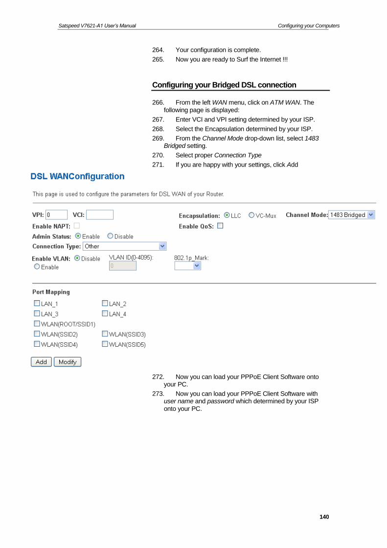
Satspeed V7621-A1 User’s Manual Configuring your Computers
140
264. Your configuration is complete.
265. Now you are ready to Surf the Internet !!!
Configuring your Bridged DSL connection
266. From the left WAN menu, click on ATM WAN. The following page is displayed:
267. Enter VCI and VPI setting determined by your ISP.
268. Select the Encapsulation determined by your ISP.
269. From the Channel Mode drop-down list, select 1483 Bridged setting.
270. Select proper Connection Type
271. If you are happy with your settings, click Add
272. Now you can load your PPPoE Client Software onto your PC.
273. Now you can load your PPPoE Client Software with user name and password which determined by your ISP onto your PC.

Satspeed V7621-A1 User’s Manual Configuring your Computers
141
Configuring your 1483 MER by DHCP
274. From the left WAN menu, click on ATM WAN. The following page is displayed:
275. Enter VCI and VPI setting determined by your ISP.
276. Select the Encapsulation determined by your ISP.
277. From the Channel Mode drop-down list, select 1483 MER setting.
278. Enable Enable NAPT
279. Select proper Connection Type
280. From the IP Protocol drop-down list, select the IP Protocol, IPv4, IPv6 or dual stacks IPv4/IPv6 determined by your ISP.
281. From the Type ratio, click DHCP.
282. IPv6 WAN setting determined by your ISP.
283. If you are happy with your settings, click Add
284. Your configuration is complete.

Satspeed V7621-A1 User’s Manual Configuring your Computers
142
285. Now you are ready to Surf the Internet !!!
Configuring your 1483 MER by Fixed IP
286. From the left WAN menu, click on ATM WAN. The following page is displayed:
287. Enter VCI and VPI setting determined by your ISP.
288. Select the Encapsulation determined by your ISP.
289. From the Channel Mode drop-down list, select 1483 MER setting.
290. Enable Enable NAPT
291. Select proper Connection Type
292. From the IP Protocol drop-down list, select the IP Protocol, IPv4, IPv6 or dual stacks IPv4/IPv6 determined by your ISP.
293. From the Type ratio, click Fixed IP.
294. Enter Local IP Address, Subnet Mask and Remote IP Address which was given by Telecom or by your Internet Service Provider (ISP).
295. IPv6 WAN setting determined by your ISP.
296. If you are happy with your settings, click Add

Satspeed V7621-A1 User’s Manual Configuring your Computers
143
297. From the left Service menu, click on DHCP.
298. Check on Set Manually ratio.
299. Enter DNS setting determined by your ISP.
300. Click Apply Changes button.
301. Click OK button.
302. Your configuration is complete.
303. Now you are ready to Surf the Internet !!!

Satspeed V7621-A1 User’s Manual Configuring your Computers
144
ATM Settings
The page is for ATM PVC QoS parameters setting. The DSL device support 4 QoS mode —CBR/rt-VBR/nrt-VBR/UBR.
304. From the left-hand WAN menu, click on ATM. The following page is displayed:

Satspeed V7621-A1 User’s Manual Configuring your Computers
145
Field Description
VPI Virtual Path Identifier. This is read-only field and is selected on the Select column in the Current ATM VC Table.
VCI Virtual Channel Identifier. This is read-only field and is selected on the Select column in the Current ATM VC
Table. The VCI, together with VPI, is used to identify the next destination of a cell as it passes through to the ATM switch.
QoS Quality of Server, a characteristic of data transmission that measures how accurately and how quickly a message or data is transferred from a source host to a destination host over a network. The four QoS options are:
−UBR (Unspecified Bit Rate): When UBR is selected, the SCR and MBS fields are disabled.
−CBR (Constant Bit Rate): When CBR is selected, the SCR and MBS fields are disabled.
−nrt-VBR (non-real-time Variable Bit Rate): When nrt-VBR is selected, the SCR and MBS fields are enabled.
−rt-VBR (real-time Variable Bit Rate): When rt-VBR is selected, the SCR and MBS fields are enabled.
PCR Peak Cell Rate, measured in cells/sec., is the cell rate which the source may never exceed.
SCR Sustained Cell Rate, measured in cells/sec., is the average cell rate over the duration of the connection.
MBS Maximum Burst Size, a traffic parameter that specifies the maximum number of cells that can be transmitted at the peak cell rate.
Function Button Description
Apply Changes Set new PVC OoS mode for the selected PVC. New parameters will take effect after save into flash memory and reboot the system. See section “Admin” for save details.
Undo Discard your settings.

Satspeed V7621-A1 User’s Manual Configuring your Computers
146
DSL Settings
The DSL setting page allows you to select any combination of DSL training modes.
305. From the left-hand WAN menu, click on DSL Settings. The following page is displayed:
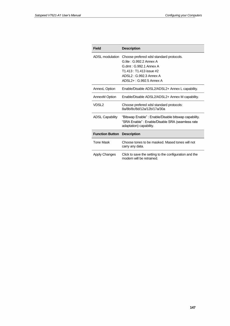
Satspeed V7621-A1 User’s Manual Configuring your Computers
147
Field Description
ADSL modulation Choose prefered xdsl standard protocols.
G.lite : G.992.2 Annex A
G.dmt : G.992.1 Annex A
T1.413 : T1.413 issue #2
ADSL2 : G.992.3 Annex A
ADSL2+ : G.992.5 Annex A
AnnexL Option Enable/Disable ADSL2/ADSL2+ Annex L capability.
AnnexM Option Enable/Disable ADSL2/ADSL2+ Annex M capability.
VDSL2 Choose prefered xdsl standard protocols: 8a/8b/8c/8d/12a/12b/17a/30a
ADSL Capability “Bitswap Enable” : Enable/Disable bitswap capability.
“SRA Enable” : Enable/Disable SRA (seamless rate adaptation) capability.
Function Button Description
Tone Mask Choose tones to be masked. Mased tones will not carry any data.
Apply Changes Click to save the setting to the configuration and the modem will be retrained.

Satspeed V7621-A1 User’s Manual Configuring your Computers
148
14 3G Settings
Please enter the APN, PIN code, user name, and password provided by your ISP. (Please note that some information might not be needed.)
306. From the left WAN menu, click on 3G Settings. The following page is displayed:
307. Enter PIN code determined by your ISP. Keep it empty if your ISP doesn't need it
308. Enter Access Point Name (APN) determined by your ISP. Keep it empty if your ISP doesn't need it
309. Enter Dial Number determined by your ISP. Keep it as default if your ISP doesn't need it
310. Enter User Name determined by your ISP. Keep it empty if your ISP doesn't need it
311. Enter Password determined by your ISP. Keep it empty if your ISP doesn't need it
312. Click Apply Changes button.

Satspeed V7621-A1 User’s Manual Configuring your Computers
149
313. Click OK button.
314. Your configuration is complete.
315. Now you are ready to Surf the Internet !!!
Option Description
3G WAN Enable or Disable 3G WAN
PIN code Enter PIN code determined by your ISP. Keep it empty if your ISP doesn't need it
APN Enter Access Point Name (APN) determined by your ISP. Keep it empty if your ISP doesn't need it
Dial Number Enter Dial Number determined by your ISP. Keep it as default if your ISP doesn't need it
Authentication Choose the proper Authentication
User Name Enter User Name determined by your ISP. Keep it empty if your ISP doesn't need it
Password Enter Password determined by your ISP. Keep it empty if your ISP doesn't need it
Connection Type Choose the proper Connection Type
Idle Time (min) Choose the proper Idle Time
NAPT Enable or Disable NAPT
Default Route Enable or Disable Default Route
Backup for ADSL Enable or Disable 3G WAN Backup
Backup Timer (sec) Configure the proper Backup Timer
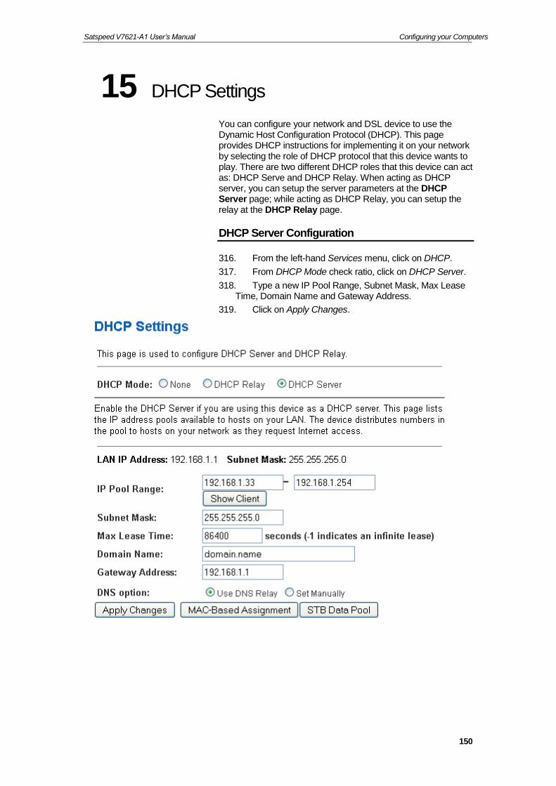
Satspeed V7621-A1 User’s Manual Configuring your Computers
150
15 DHCP Settings
You can configure your network and DSL device to use the Dynamic Host Configuration Protocol (DHCP). This page provides DHCP instructions for implementing it on your network by selecting the role of DHCP protocol that this device wants to play. There are two different DHCP roles that this device can act as: DHCP Serve and DHCP Relay. When acting as DHCP server, you can setup the server parameters at the DHCP Server page; while acting as DHCP Relay, you can setup the relay at the DHCP Relay page.
DHCP Server Configuration
316. From the left-hand Services menu, click on DHCP.
317. From DHCP Mode check ratio, click on DHCP Server.
318. Type a new IP Pool Range, Subnet Mask, Max Lease Time, Domain Name and Gateway Address.
319. Click on Apply Changes.

Satspeed V7621-A1 User’s Manual Configuring your Computers
151
320. Click OK button.
Field Description
IP Pool Range Specify the lowest and highest addresses in the pool.
Max Lease Time The Lease Time is the amount of time that a network user is allowed to maintain a network connection to the device using the current dynamic IP address. At the end of the Lease Time, the lease is either renewed or a new IP is issued by the DHCP server. The amount of time is in units of seconds. The default value is 86400 seconds (1 day). The value –1 stands for the infinite lease.
Domain Name A user-friendly name that refers to the group of hosts (subnet) that will be assigned addresses from this pool.
Function Button Description
Apply Changes Set new DHCP server configuration. New parameters will take effect after save into flash memory and reboot the system. See section “Admin” for save details.
MAC-Based Assignment
Configure the static IP base on MAC Address. You can assign/delete the static IP.

Satspeed V7621-A1 User’s Manual Configuring your Computers
152
DHCP Relay Configuration
321. From the left-hand Services menu, click on DHCP.
322. From DHCP Mode check ratio, click on DHCP Relay.
323. Type DHCP server IP Addresses.
324. Click on Apply Changes.
325. Click OK button.
326. You need to renew your DHCP lease:
Windows 95/98
a. Select Run... from the Start menu.
b. Enter winipcfg and click OK.
c. Select your ethernet adaptor from the pull-down menu
d. Click Release All and then Renew All.
e. Exit the winipcfg dialog.
Windows NT/Windows 2000/Windows XP
a. Bring up a command window.
Field Description
DHCP Server Address
Specify the IP address of your ISP’s DHCP server. Requests for IP information from your LAN will be passed to the default gateway, which should route the request appropriately.
Function Button Description
Apply Changes Set new DHCP server configuration. New parameters will take effect after save into flash memory and reboot the system. See section “Admin” for save details.

Satspeed V7621-A1 User’s Manual Configuring your Computers
153
b. Type ipconfig /release in the command window.
c. Type ipconfig /renew.
d. Type exit to close the command window.
Linux
a. Bring up a shell.
b. Type pump -r to release the lease.
c. Type pump to renew the lease.
DHCP None Configuration
327. From the left-hand Services menu, click on DHCP.
328. From DHCP Mode check ratio, click on None.
329. Click on Apply Changes.
330. Click OK button.
Function Button Description
Apply Changes Set new DHCP server configuration. New parameters will take effect after save into flash memory and reboot the system. See section “Admin” for save details.

Satspeed V7621-A1 User’s Manual Configuring your Computers
154
16 DHCPv6 Settings
You can configure your network and DSL device to use the Dynamic Host Configuration Protocol (DHCP). This page provides DHCP instructions for implementing it on your network by selecting the role of DHCP protocol that this device wants to play. There are two different DHCP roles that this device can act as: DHCP Serve and DHCP Relay. When acting as DHCP server, you can setup the server parameters at the DHCP Server page; while acting as DHCP Relay, you can setup the relay at the DHCP Relay page.
DHCP Server (Manual) Configuration
331. From the left-hand Advance menu, click on IPv6 - DHCPv6.
332. From DHCPv6 Mode check ratio, click on DHCP Server (Manual).
333. Type a new IP Pool Range and Prefix Length.
334. Click on Apply Changes.

Satspeed V7621-A1 User’s Manual Configuring your Computers
155

Satspeed V7621-A1 User’s Manual Configuring your Computers
156
335. Click OK button.
Field Description
IP Pool Range Specify the lowest and highest addresses in the pool.
Prefix Length Configure Prefix Length
Valid Lifetime Configure Valid Lifetime
Preferred Lifetime
Configure Preferred Lifetime
Renew Time Configure Renew Time
Rebind Time Configure Rebind Time
Client DUID Configure Client DUID
Domain Name A user-friendly name that refers to the group of hosts (subnet) that will be assigned addresses from this pool.
Function Button Description
Apply Changes Set new DHCP server configuration. New parameters will take effect after save into flash memory and reboot the system. See section “Admin” for save details.

Satspeed V7621-A1 User’s Manual Configuring your Computers
157
DHCP Server (Auto) Configuration
336. From the left-hand Services menu, click on DHCPv6.
337. From DHCPv6 Mode check ratio, click on DHCP Server (Auto).
338. Click on Apply Changes.
339. Click OK button.
Function Button Description
Apply Changes Set new DHCP server configuration. New parameters will take effect after save into flash memory and reboot the system. See section “Admin” for save details.

Satspeed V7621-A1 User’s Manual Configuring your Computers
158
DHCP Relay Configuration
340. From the left-hand Services menu, click on DHCP.
341. From DHCPv6 Mode check ratio, click on DHCP Relay.
342. Configure the Upper Interface (server link).
343. Click on Apply Changes.
344. Click OK button.
345. You need to renew your DHCP lease:
Windows 95/98
a. Select Run... from the Start menu.
b. Enter winipcfg and click OK.
c. Select your ethernet adaptor from the pull-down menu
d. Click Release All and then Renew All.
e. Exit the winipcfg dialog.
Windows NT/Windows 2000/Windows XP
Field Description
Upper Interface Configure the upper interface (server link)
Function Button Description
Apply Changes Set new DHCP server configuration. New parameters will take effect after save into flash memory and reboot the system. See section “Admin” for save details.

Satspeed V7621-A1 User’s Manual Configuring your Computers
159
a. Bring up a command window.
b. Type ipconfig /release in the command window.
c. Type ipconfig /renew.
d. Type exit to close the command window.
Linux
a. Bring up a shell.
b. Type pump -r to release the lease.
c. Type pump to renew the lease.
DHCP None Configuration
346. From the left-hand Services menu, click on DHCP.
347. From DHCPv6 Mode check ratio, click on None.
348. Click on Apply Changes.
349. Click OK button.
Function Button Description
Apply Changes Set new DHCP server configuration. New parameters will take effect after save into flash memory and reboot the system. See section “Admin” for save details.

Satspeed V7621-A1 User’s Manual Configuring your Computers
160
17 DNS Configuration
This page is used to configure the DNS server ip addresses for DNS Relay.
DHCP Server Configuration - Attain DNS Automatically
350. From the left Services menu, click on DNS -> DNS Server.
351. From check ratio, click on Attain DNS Automatically.
352. Click on Apply Changes.
353. Click OK button.
Field Description
Attain DNS Automatically
Select this item if you want to use the DNS servers obtained by the WAN interface via the auto-configuration mechanism.
Set DNS Manually
Select this item to configure up to three DNS IP addresses.
Function Button Description
Apply Changes Set new DNS relay configuration. New parameters will take effect after save into flash memory and reboot the system. See section “Admin” for save details.

Satspeed V7621-A1 User’s Manual Configuring your Computers
161
DHCP Server Configuration - Set DNS Manually
354. From the left Services menu, click on DNS -> DNS Server.
355. From check ratio, click on Set DNS Manually.
356. Enter the IP Address of DNS.
357. Click on Apply Changes.
Field Description
IPv4 WAN Interface Binding
Enable or disable IPv4 WAN Interface Binding
DNSv4 1/2/3 Select this item to configure up to three DNSv4 IP addresses.
IPv6 WAN Interface Binding
Enable or disable IPv6 WAN Interface Binding
DNSv6 1/2/3 Select this item to configure up to three DNSv6 IP addresses.
Function Button Description
Apply Changes Set new DNS relay configuration. New parameters will take effect after save into flash memory and reboot the system. See section “Admin” for save details.

Satspeed V7621-A1 User’s Manual Configuring your Computers
162
358. Click OK button.

Satspeed V7621-A1 User’s Manual Configuring your Computers
163
18 Dynamic DNS Configuration
Overview of Dynamic DNS
If some host has a dynamic IP address that keeps changing frequently, it is difficult to keep updating the IP record that is associated with the domain name of this host in the zone files. This will result in non-accessibility of this host on the Internet. Dynamic DNS service allows to keep mapping of a dynamic IP address of such host to a static hostname. Dynamic DNS services are provided by many websites. The host needs to register with some website and get a domain name. When the IP address of the host changes, it just needs to send a message to the website that's providing dynamic DNS service to this host. For this to work, an automated update client needs to be implemented. These update clients send update messages to the servers whenever there is some change in the IP address of that host. Then, the server updates the entries for that host and replies back with some return code.
Above Figure explains one such scenario in which a host gets a dynamic IP address for itself from a DHCP server. As the host has registered with one of the dynamic DNS service providers on the Internet, it sends an update message to the service provider with host name and changed IP address. The service provider updates the new IP address of the host in the zone files that have entry for that host name and replies back with some return code. The return code communicates the success or failure of the update message. This process is repeated every time the host's IP address changes.
If the dynamic DNS service provider is notified of the same IP address again and again, then it considers it an abuse and might block the host name. To avoid this scenario, the IP address that was successfully updated to the ISP is stored on the unit. Whenever we receive an IP address change notification, the new IP address is compared with the IP address that was stored on the last update. If they differ, then only an

Satspeed V7621-A1 User’s Manual Configuring your Computers
164
update request is sent. However, when the system comes up there is no way of knowing what was the IP address on last successful update before the system went down. You need to give the command “system config save“ periodically to save this IP address on Flash.
Registering With Dynamic DNS Service Provider
Currently, Wireless VDSL2 Router supports two Dynamic DNS service providers, www.tzo.com and www.dyndns.com. To use their Dynamic DNS service, you first need to visit the Web site of a service provider and register. While registering, you need to provide your username, password, and hostname as mandatory parameters. A service provider may also prompt you to fill some optional parameters.
Configuring IP Interfaces
You need to create a Dynamic DNS interface per IP interface and can only create one Dynamic DNS interface service on one IP interface. For more information on creating IP interfaces, refer to section Creating IP interfaces.
Note
www.dyndns.org provides three kinds of services - Dynamic DNS, Custom DNS and Static DNS. You can create different domains in these systems. Custom DNS service is a full DNS solution for newly purchased domains or domains you already own. A web-based interface provides complete control over resource records and your entire domain, including support for dynamic IPs and automated updates. Static DNS service points a DNS hostname in some domain owned by dyndns.org to the user's ISP-assigned static or pseudo-static IP address.
DynDNS service points a fixed hostname in some domain owned by dyndns.org to the user's ISP-assigned dynamic IP address. This allows more frequent update of IP addresses, than allowed by Static DNS.

Satspeed V7621-A1 User’s Manual Configuring your Computers
165
Dynamic DNS Configuration – DynDNS.org
359. From the left Services menu, click on DNS -> Dynamic DNS.
360. Check the Enable check box.
361. From DDNS provider drop-down list, select DynDNS.org.
362. Enter the Hostname.
363. Enter the Username.
364. Enter the Password.
365. Click Add button.
Field Description
Enable Check this item to enable this registration account for the DNS server.
DDNS provider There are two DDNS providers to be selected in order to register your device with: DynDNS and TZO. A charge may occur depends on the service you select.
Hostname Domain name to be registered with the DDNS server.
Username User-name assigned by the DDNS service provider.
Password Password assigned by the DDNS service provider.

Satspeed V7621-A1 User’s Manual Configuring your Computers
166
366. Configure Dynamic DNS setting successfully!
Dynamic DNS Configuration – TZO
367. From the left-hand Services menu, click on DNS -> Dynamic DNS.
368. From DDNS provider drop-down list, select TZO.
369. Enter the Hostname.
370. From Interface drop-down list, select proper one.
371. Check the Enable check box.
372. Enter the Hostname, Email and Password.
373. Click Add button.
Function Button Description
Add Click Add to add this registration into the configuration.
Remove Select an existing DDNS registration by clicking the radio button at the Select column of the Dynamic DNS Table. Click Remove button to remove the selected registration from the configuration.

Satspeed V7621-A1 User’s Manual Configuring your Computers
167
374. Configure Dynamic DNS setting successfully!
Field Description
Enable Check this item to enable this registration account for the DNS server.
DDNS provider There are two DDNS providers to be selected in order to register your device with: DynDNS and TZO. A charge may occurs depends on the service you select.
Hostname Domain name to be registered with the DDNS server.
Email Email that applied for the DDNS service provider.
Key Key assigned by the DDNS service provider.
Function Button Description
Add Click Add to add this registration into the configuration.
Modify Click Modify to modify this registration into the configuration.
Remove Select an existing DDNS registration by clicking the radio button at the Select column of the Dynamic DNS Table. Click Remove button to remove the selected registration from the configuration.

Satspeed V7621-A1 User’s Manual Configuring your Computers
168
19 IP/Port Filtering
Firewall contains several features that are used to deny or allow traffic from passing through the device.
The IP/Port filtering feature allows you to deny/allow specific services or applications in the forwarding path.
IP/Port Filtering
375. From the left Services menu, click on Firewall -> IP/Port Filtering.
Fields on the first setting block
Description
Outgoing Default Action
Specify the default action on the LAN to WAN forwarding path.
Incoming Default Action
Specify the default action on the WAN to LAN forwarding path.
Function Button Description
Apply Changes Click to save the setting of default actions to the configuration.
Fields on the second setting block
Description

Satspeed V7621-A1 User’s Manual Configuring your Computers
169
Rule Action Deny or allow traffic when matching this rule.
Direction Traffic forwarding direction.
Protocol There are 3 options available: TCP, UDP and ICMP.
Source IP Address
The source IP address assigned to the traffic on which filtering is applied.
Source Subnet Mask
Subnet-mask of the source IP.
Source Port Starting and ending source port numbers.
Destination IP Address
The destination IP address assigned to the traffic on which filtering is applied.
Destination Subnet Mask
Subnet-mask of the destination IP.
Destination Port Starting and ending destination port numbers.
Function Button Description
Add Click to save the rule entry to the configuration.
Delete Selected Delete selected filtering rules from the filter table. You can click the checkbox at the Select column to select the filtering rule.
Delete All Delete all filtering rules from the filter table.

Satspeed V7621-A1 User’s Manual Configuring your Computers
170
20 MAC Filtering
The MAC filtering feature allows you to define rules to allow or deny frames through the device based on source MAC address, destination MAC address, and traffic direction.
Configuring MAC filtering to Deny for outgoing access
376. From the left Services menu, click on Firewall -> MAC Filtering.
377. From the Direction drop-down list, select Outing setting
378. From the Rule Action check ratio, select Deny
379. Enter the MAC Address that you want to deny for outgoing access in the Source MAC Address
380. Click Add
381. Configure MAC filtering setting successfully!

Satspeed V7621-A1 User’s Manual Configuring your Computers
171
Fields on the first setting block
Description
Outgoing Default Action
Specify the default action on the LAN to WAN bridging/forwarding path.
Incoming Default Action
Specify the default action on the WAN to LAN bridging/forwarding path.
Function Button Description
Apply Changes Click to change the setting of default actions to the configuration.
Fields on the second setting block
Description
Rule Action Deny or allow traffic when matching this rule.
Direction Traffic bridging/forwarding direction.
Source MAC Address
The source MAC address. It must be xxxxxxxxxxxx format. Blanks can be used in the MAC address space and are considered as don’t care.
Destination MAC Address
The destination MAC address. It must be xxxxxxxxxxxx format. Blanks can be used in the MAC address space and are considered as don’t care.
Function Button Description
Delete Selected Delete selected filtering rules from the filter table. You can click the checkbox at the Select column to select
the filtering rule.
Delete All Delete all filtering rules from the filter table.

Satspeed V7621-A1 User’s Manual Configuring your Computers
172
21 Port Forwarding
Entries in this table allow you to automatically redirect common network services to a specific machine behind the NAT firewall. These settings are only necessary if you wish to host some sort of server like a web server or mail server on the private local network behind your Gateway's NAT firewall.
Your device has built in advanced Security features that protect your network by blocking unwanted traffic from the Internet.
If you simply want to connect from your local network to the Internet, you do not need to make any changes to the default Security configuration. You only need to edit the configuration if you wish to do one or both of the following:
allow Internet users to browse the user pages on your local network (for example, by providing an FTP or HTTP server)
play certain games which require accessibility from the Internet
This chapter describes how to configure Security to suit the needs of your network.
By default, the IP addresses of your LAN PCs are hidden from the Internet. All data sent from your LAN PCs to a PC on the Internet appears to come from the IP address of your device.
In this way, details about your LAN PCs remain private. This security feature is called Port Forwarding.
382. From the left Services menu, click on Firewall -> Port Forwarding.

Satspeed V7621-A1 User’s Manual Configuring your Computers
173

Satspeed V7621-A1 User’s Manual Configuring your Computers
174
Port Forwarding for TCP with specified IP
Please follow example below to configure the Port Forwarding to Specified IP with TCP.
383. From the left Services menu, click on Firewall -> Port Forwarding.

Satspeed V7621-A1 User’s Manual Configuring your Computers
175
384. Check the option Enable Port Forwarding to enable the Enable Port Forwarding.
385. Click Apply Changes.
386. Enter any comment in Comment field.
387. Enter the IP Address and port you want to be forwarded in IP Address / Local Port from / Local Port to field.
388. From the Protocol drop-down list, select TCP setting.
389. Click Add.
390. Now the IP Address and port range that you created has been added and listed in the Current Filter Table.
391. Now the port range of the IP Address in the Current Filter Table can be access from Internet by TCP protocol.
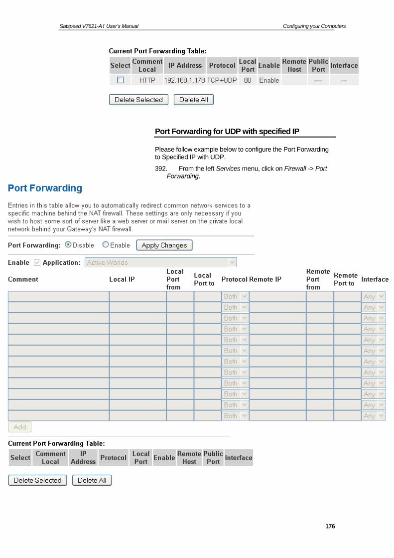
Satspeed V7621-A1 User’s Manual Configuring your Computers
176
Port Forwarding for UDP with specified IP
Please follow example below to configure the Port Forwarding to Specified IP with UDP.
392. From the left Services menu, click on Firewall -> Port Forwarding.

Satspeed V7621-A1 User’s Manual Configuring your Computers
177
393. Check the option Enable Port Forwarding to enable the Enable Port Forwarding.
394. Click Apply Changes.
395. Enter any comment in Comment field.
396. Enter the IP Address and port you want to be forwarded in IP Address / Local Port from / Local Port to field.
397. From the Protocol drop-down list, select UDP setting.
398. Click Add.
399. Now the IP Address and port range that you created has been added and listed in the Current Filter Table.
400. Now the port range of the IP Address in the Current Filter Table can be access from Internet by UDP protocol.

Satspeed V7621-A1 User’s Manual Configuring your Computers
178
22 URL Blocking
The URL Blocking is the web filtering solution. The firewall includes the ability to block access to specific web URLs based on string matches. This can allow large numbers of URLs to be blocked by specifying a Keyword. The URL Blocking enforce a Web usage policy to control content downloaded from, and uploaded to, the Web.
Configuring URL Blocking of FQDN
401. From the left Services menu, click on Firewall -> URL Blocking.
Fields on the first setting block
Description
URL Blocking Check this item to enable the URL Blocking feature.
Keyword The filtered keyword such as yahoo. If the URL includes this keyword, the URL will be blocked to access.
Function Button Description

Satspeed V7621-A1 User’s Manual Configuring your Computers
179
402. From the URL Blocking check ratio, check on Enable
403. Click Apply Changes
404. Type the FQDN in the FQDN field.
405. Click Add
406. Configure URL Blocking of FQDN setting successfully!
Apply Changes Click to disable/enable the URL Blocking capability
Add FQDN Add FQDN into URL Blocking table.
Delete Selected FQDN
Delete the selected FQDN from the URL Blocking table. You can click the checkbox at the Select column to select the Blocked FQDN.
Add Filtered Keyword
Add filtered keyword into Keyword Filtering table.
Delete Selected Keyword
Delete the selected keyword from the keyword Filtering table. You can click the checkbox at the Select column to select the filtered keyword.

Satspeed V7621-A1 User’s Manual Configuring your Computers
180
Configuring URL Blocking of Keyword
407. From the left Services menu, click on Firewall -> URL Blocking.
Fields on the first setting block
Description
URL Blocking Check this item to enable the URL Blocking feature.
Keyword The filtered keyword such as yahoo. If the URL includes this keyword, the URL will be blocked to access.
Function Button Description
Apply Changes Click to disable/enable the URL Blocking capability
Add FQDN Add FQDN into URL Blocking table.
Delete Selected FQDN
Delete the selected FQDN from the URL Blocking table. You can click the checkbox at the Select column to select the Blocked FQDN.
Add Filtered Keyword
Add filtered keyword into Keyword Filtering table.
Delete Selected Keyword
Delete the selected keyword from the keyword Filtering table. You can click the checkbox at the Select column to select the filtered keyword.

Satspeed V7621-A1 User’s Manual Configuring your Computers
181
408. From the URL Blocking check ratio, check on Enable
409. Click Apply Changes
410. Type the Keyword in the Keyword field.
411. Click Add
412. Configure URL Blocking of Keyword setting successfully!

Satspeed V7621-A1 User’s Manual Configuring your Computers
182
23 Domain Blocking
This page is used to configure the Blocked domain. Here you can add/delete the blocked domain.
Configuring Domain Blocking
413. From the left Services menu, click on Firewall -> Domain Blocking.
Fields on the first setting block
Description
Domain Blocking Check this item to enable the Domain Blocking feature.
Domain The Domain such as www.yahoo.com. If the URL includes this domain, the domain will be blocked to access.
Function Button Description
Apply Changes Click to disable/enable the URL Blocking capability
Add FQDN Add FQDN into URL Blocking table.
Delete Selected Delete the selected Domain Blocking from the Domain Blocking table. You can click the checkbox at the Select column to select the Blocked Domain.

Satspeed V7621-A1 User’s Manual Configuring your Computers
183
414. From the Domain Blocking check ratio, check on Enable
415. Click Apply Changes
416. Type the Domain in the Domain field.
417. Click Add
418. Configure URL Blocking of FQDN setting successfully!
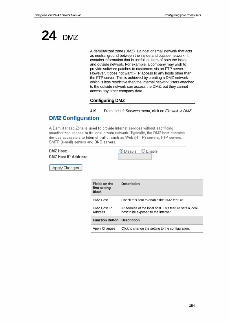
Satspeed V7621-A1 User’s Manual Configuring your Computers
184
24 DMZ
A demilitarized zone (DMZ) is a host or small network that acts as neutral ground between the inside and outside network. It contains information that is useful to users of both the inside and outside network. For example, a company may wish to provide software patches to customers via an FTP server. However, it does not want FTP access to any hosts other than the FTP server. This is achieved by creating a DMZ network which is less restrictive than the internal network.Users attached to the outside network can access the DMZ, but they cannot access any other company data.
Configuring DMZ
419. From the left Services menu, click on Firewall -> DMZ.
Fields on the first setting block
Description
DMZ Host Check this item to enable the DMZ feature.
DMZ Host IP Address
IP address of the local host. This feature sets a local host to be exposed to the Internet.
Function Button Description
Apply Changes Click to change the setting to the configuration.
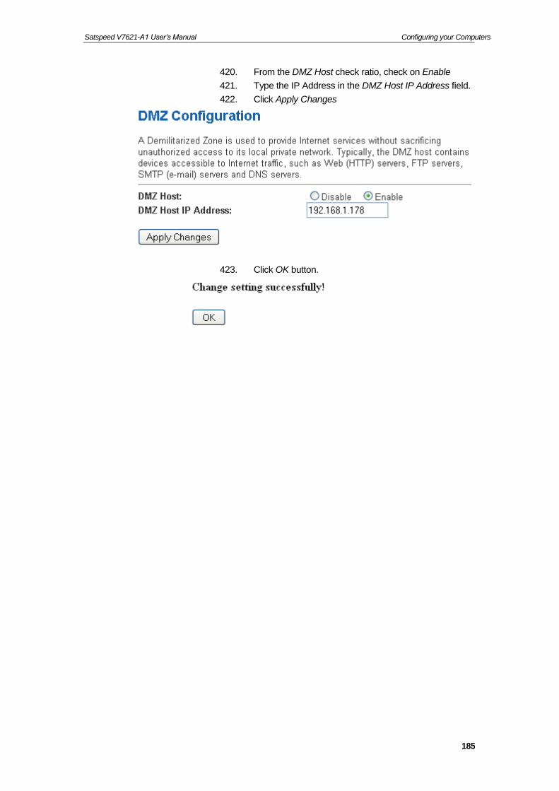
Satspeed V7621-A1 User’s Manual Configuring your Computers
185
420. From the DMZ Host check ratio, check on Enable
421. Type the IP Address in the DMZ Host IP Address field.
422. Click Apply Changes
423. Click OK button.

Satspeed V7621-A1 User’s Manual Configuring your Computers
186
25 UPnP
UPnP is an architecture for pervasive peer-to-peer network connectivity of intelligent appliances, Wireless devices, and PCs of all form factors. It is designed to bring easy-to-use, flexible, standards-based connectivity to ad-hoc or unmanaged networks whether in the home, in a small business, public spaces, or attached to the Internet. UPnP is a distributed, open networking architecture that leverages TCP/IP and the Web technologies to enable seamless proximity networking in addition to control and data transfer among networked devices in the home, office, and public spaces.
UPnP is more than just a simple extension of the plug and play peripheral model. It is designed to support zero-configuration, "invisible" networking, and automatic discovery for a breadth of device categories from a wide range of vendors. This means a device can dynamically join a network, obtain an IP address, convey its capabilities, and learn about the presence and capabilities of other devices. DHCP and DNS servers are optional and are used only if available on the network. Finally, a device can leave a network smoothly and automatically without leaving any unwanted state behind.
The DSL device supports a control point for Universal Plug and Play (UPnP) version 1.0, and supports two key features: NAT Traversal and Device Identification. This feature requires one active WAN interface. In addition, the host should support this feature. In the presence of multiple WAN interfaces, select an interface on which the incoming traffic is present.
With NAT Traversal, when an UPnP command is received to open ports in NAT, the application translates the request into system commands to open the ports in NAT and the firewall. The interface to open the ports on is given to UPnP when it starts up and is part of the configuration of the application.
For Device Identification, the application will send a description of the DSL device as a control point back to the host making the request.

Satspeed V7621-A1 User’s Manual Configuring your Computers
187
From the web page you can enable or disable UPnP.
Configuring UPnP
424. From the left Services menu, click on UPnP. The following page is displayed:
425. From the UPnP check ratio, check on Enable
426. Select a WAN Interface from the WAN Interface drop-down list.
427. Click Apply Changes
Fields on the first setting block
Description
UPnP Enable/disable UPnP feature.
WAN Interface Select WAN interface that will use UPnP from the drop-down lists.
Function Button Description
Apply Changes Click to save the setting to the configuration.

Satspeed V7621-A1 User’s Manual Configuring your Computers
188
428. Click OK button.
UPnP Control Point Software on Windows ME
To install the control point software on Windows ME:
1. In the Control Panel, select "Add/Remove Programs".
2. In the "Add/Remove Programs Properties" dialog box, select the "Windows Setup" tab. In the "Components" list, double click on the "Communications" entry.
3. In the "Communications" dialog box, scroll down the "Components" list to display the UPnP entry. Select the entry, click "OK".
4. Click "OK" to finish the "Add/Remove Programs" dialog.
5. Reboot your system.
Once you have installed the UPnP software and you have rebooted (and your network includes the IGD system), you should be able to see the IGD controlled device on your network.
UPnP Control Point Software on Windows XP with Firewall
On Windows XP versions earlier than SP2, Firewall support is provided by the Windows XP Internet Connection Firewall. You cannot use the Windows XP Internet Connection Firewall support on a system that you intend to use as a UPnP control point. If this feature is enabled, although the control point system may display controlled devices in the list of network devices, the control point system cannot participate in UPnP communication. (This restriction also applies to controlled devices running on Windows XP systems earlier than SP2.)
On Windows XP SP2 and later, Firewall support is provided by Windows Firewall. Unlike earlier versions, Windows XP SP2 can be used on a system that you intend to use as a UPnP control point.
To turn off the Firewall capability on any version of Windows XP, follow the steps below:
1. In the Control Panel, select "Network and Internet Connections".
2. In the "Network and Internet Connections" dialog box, select "Network Connections".
3. In the "Network Connections" dialog box, right-click on the local area connection entry for your network; this will display a menu. Select the "Properties" menu entry.

Satspeed V7621-A1 User’s Manual Configuring your Computers
189
4. In the "Local Area Connection Properties" dialog box, select the "Advanced" tab. Disable the Internet Connection Firewall by de-selecting the entry with the following label:
"Protect my computer and network by limiting or preventing access to the computer from the Internet".
5. Click "OK".
SSDP requirements
You must have SSDP Discovery Service enabled on your Windows XP system to use the UPnP Control point software.
SSDP Discovery Service is enabled on a default installation of Windows XP. To check if it is enabled on your system, look in Control Panel > Administrative Tools > Services).

Satspeed V7621-A1 User’s Manual Configuring your Computers
190
Installation procedure
To install the Control point software on Windows XP, follow the steps below:
1. In the Control Panel, select "Add/Remove Programs".
2. In the "Add or Remove Programs" dialog box, click the "Add / Remove Windows Components" button.
3. In the "Windows Component Wizard" dialog box, scroll down the list to display the "Networking Services" entry. Highlight (select) the entry, and click on the "Details" button.
4. The “Networking Services” window is displayed.
The subcomponents shown in the Networking Services window will be different depending on if you are using Windows XP, Windows XP (SP1), or Windows XP (SP2).
If you are using Windows XP SP2, the Networking Services window will display the following list of sub-components:
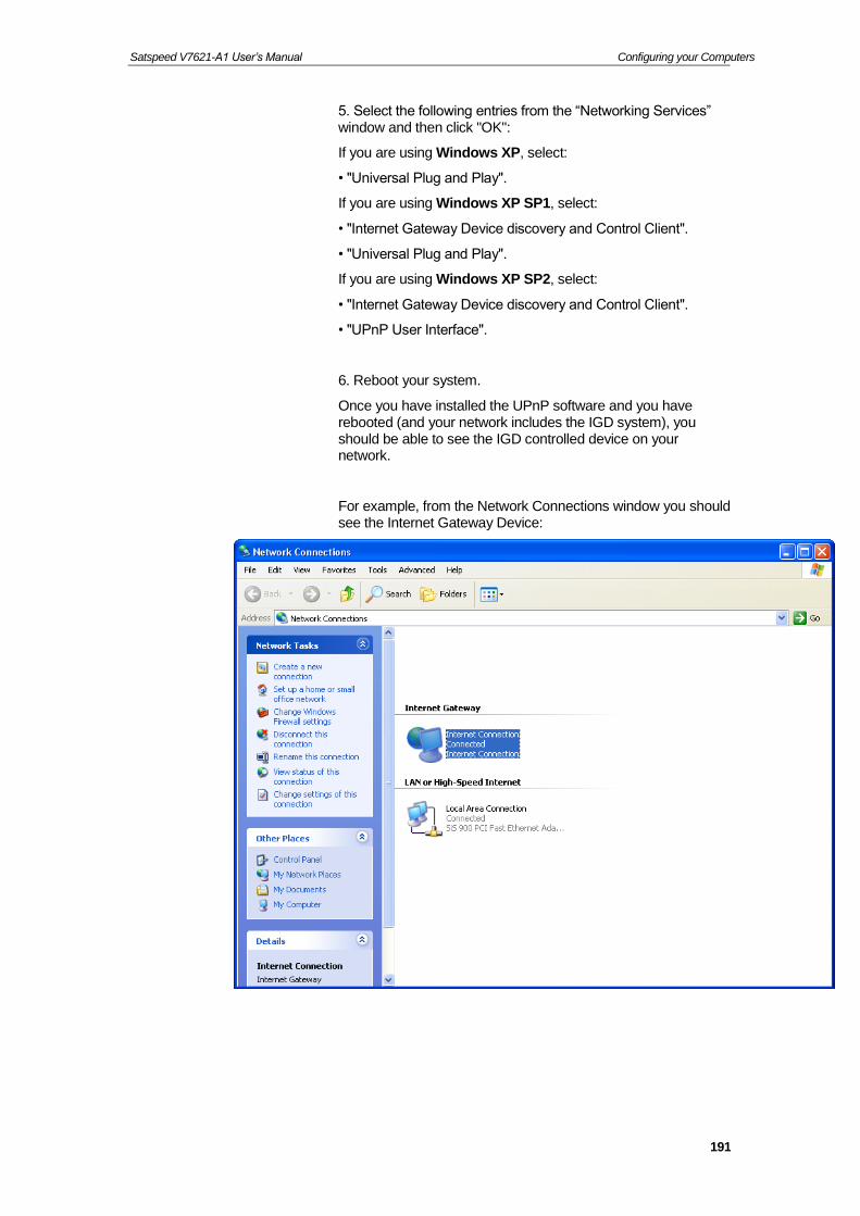
Satspeed V7621-A1 User’s Manual Configuring your Computers
191
5. Select the following entries from the “Networking Services” window and then click "OK":
If you are using Windows XP, select:
• "Universal Plug and Play".
If you are using Windows XP SP1, select:
• "Internet Gateway Device discovery and Control Client".
• "Universal Plug and Play".
If you are using Windows XP SP2, select:
• "Internet Gateway Device discovery and Control Client".
• "UPnP User Interface".
6. Reboot your system.
Once you have installed the UPnP software and you have rebooted (and your network includes the IGD system), you should be able to see the IGD controlled device on your network.
For example, from the Network Connections window you should see the Internet Gateway Device:

Satspeed V7621-A1 User’s Manual Configuring your Computers
192
26 RIP
RIP is an Internet protocol you can set up to share routing table information with other routing devices on your LAN, at your ISP’s location, or on remote networks connected to your network via the DSL line.
Most small home or office networks do not need to use RIP; they have only one Router,such as the DSL Router, and one path to an ISP. In these cases, there is no need to share routes, because all Internet data from the network is sent to the same ISP gateway.
You may want to configure RIP if any of the following circumstances apply to your network:
−Your home network setup includes an additional Router or RIP-enabled PC (other than the DSL Router). The DSL Router and the Router will need to communicate via RIP to share their routing tables.
−Your network connects via the DSL line to a remote network, such as a corporate network. In order for your LAN to learn the routes used within your corporate network, they should both be configured with RIP.
−Your ISP requests that you run RIP for communication with devices on their network.
429. From the left Advance menu, click on Route -> RIP. The following page is displayed:

Satspeed V7621-A1 User’s Manual Configuring your Computers
193
Fields on the first setting block
Description
RIP Enable/disable RIP feature.
Fields on the second setting block:
Description
Interface The name of the interface on which you want to enable RIP.
Receive Mode Indicate the RIP version in which information must be passed to the DSL device in order for it to be accepted into its routing table.
Send Mode Indicate the RIP version this interface will use when it sends its route information to other devices.
Function buttons for the second setting block in this page
Description
Add Add a RIP entry and the new RIP entry will be display in the table
Delete Selected Entry
Delete a selected RIP entry. The RIP entry can be selected on the Select column of the RIP Config Table.
Delete All Entry Delete All RIP entry.

Satspeed V7621-A1 User’s Manual Configuring your Computers
194
27 Samba
This page let user to config Samba.
Samba
430. From the left Services menu, click on Samba.
431. Click OK button.
Fields on the first setting block
Description
Digital Media Server
Enable/disable the Digital Media Server
Function buttons
Description
Apply Changes Save this bridge configuration. New configuration will take effect after saving into flash memory and rebooting the system. See section “Admin” for details.

Satspeed V7621-A1 User’s Manual Configuring your Computers
195
28 VoIP Configuration
Introduction
The Wireless VoIP Gateway Voice software release provides a software architecture for telephony applications. The software consists of real-time voice and signal processing software that perform many of the required telephony data processing functions.
VoIP enables telephone calls to be made over an IP network.
Voice Terminology
FXS refers to the low-cost phone ports (digitally connected on the board to VoIP).
The product provides Internet access using Ethenet for the LAN computers.
The phones connected to the Voice-Wireless VoIP Gateway system are standard analog phones that are identical to the other telephones connected to the Home telephone wiring system. The phones can use DTMF dialing to make VoIP calls.
The Voice-Wireless VoIP Gateway system will route or receive calls over VoIP depending on the dialed telephone number or the way in which an incoming call is received.
QoS (Quality of Service) is also used to ensure voice calls are placed at a higher priority than data traffic routed between the LAN and WAN interface.
Voice Terminology
Low Density Voice
The term used to refer to a build of the Wireless VoIP Gateway Voice Processing software with support for one FXS port.
FXS
Telephones, fax machines, and modems are examples of telephony devices. These devices typically connect (via telephone lines) to RJ11-jack Foreign Exchange Station (FXS) interfaces on telephony hardware. The FXS interface provides battery, signalling and an audio connection for the devices.
SLIC
For voltage control to the telephone line, a special hardware interface, a Subscriber Line Interface Circuit (SLIC), is required. The SLIC contains circuitry for detecting telephone line events.

Satspeed V7621-A1 User’s Manual Configuring your Computers
196
For FXS ports the SLIC generates FXS signalling.
For example, telephone line events are generated when picking up or hanging up a telephone.
Commanding a phone to ring is an example of telephone line signalling. SLIC integrated circuits may handle single or multiple FXS ports.
Codec
Audio data from the FXS port is sampled via an analog-to-digital converter, and audio data to the FXS port is generated via a digital-to-analog converter. These functions are integrated into a single circuit, the codec (short for coder-decoder, since typically, codecs encode/decode audio samples using 8-bit or 16-bit PCM encoding). Codec integrated circuits may handle bi-directional audio data on single or multiple FXS ports.
The codec produces a constant stream of audio data in a Time Division Multiplexed (TDM) fashion, which places the audio data from each port into time slots. The TDM transmission is synchronized into ‘frames’ of audio data by aligning with the codec's ‘frame sync’ signal. An FXS port's time slot is referred to as an ‘audio channel.’
In a typical Voice-Wireless VoIP Gateway system the Codec is a separate chip but it is more accurate to view the codec as an integral component of the overall SLIC chipset functionality.
Note
The algorithms used to encode/decode data on the Voice DSP are also called Codecs - eg. G.711, G.726 codecs.
Voice DSP
A Voice DSP accepts serial data from the SLIC/Codec chipset via an integrated peripheral serial port that selects the proper audio channel in hardware.
Audio data format
The audio data for digital signal processing performed internally in the DSP must be in linear data format; that is, audio data must be signed, 14-bit quantized audio samples. Wireless VoIP Gateway Voice software processing for compression and tone detection is always performed on linear data, and processing for decompression always produces linear data.
The codecs used in the Voice reference designs and Evaluation boards are programmed to encode audio data into a-Law and μ -Law data (8-bits per sample) if required. This is data is then converted to linear data for processing by the Voice DSP. The Voice DSP, after processing, converts the audio from 14-bit linear data into either G.711, G.726 or G.729ab compressed data so that it uses a lower bit-rate when sent over IP.

Satspeed V7621-A1 User’s Manual Configuring your Computers
197
Voice processing software
Voice protocol software
• Health Monitor to monitor the state of the IP connection and indicate this status to on-board LEDs.
Telephony data processing features
The main telephony data processing functions supported in the Wireless VoIP Gateway Voice software release are listed below:
• Voice codec support:
• G.711 (A-Law and μ−Law),
• G.726 (32kb) and
• G.729ab
The codecs can be dynamically changed during a call.
• Echo cancellation (G.168, 32ms echo-tail (configurable))
• Silence suppression (Voice Activity Detection (VAD)) and Comfort Noise Generation (CNG).
• Dynamic Packet Loss Compensation.
• Configurable Adaptive Jitter buffer.
• Telephony timing synchronization with Time Division Multiplexed (TDM) audio data.
• Fax and Modem tone detection.
• DTMF generation and detection.
• Highly configurable and versatile Tone generator for call progress tones and special information tones.
Voice protocol software
The following protocols are supported:
• SIP (Session Initiation Protocol). See RFC 3261.
SIP uses a peer-to-peer model, which has several advantages, including scalability. With SIP the call control is performed in the devices that terminate the call, not in some central Call Agent. The control of the call is performed directly between the two ends of the call. There can be intermediate nodes, which are used in call establishment, these are known as proxies (or proxy servers). The use of proxies in the network is not mandatory but has advantages for modularity and scalability.

Satspeed V7621-A1 User’s Manual Configuring your Computers
198
SIP features
SIP stands for Session Initiation Protocol (SIP), an application-layer control (signalling) protocol for creating, modifying, and terminating sessions with one or more participants.
These sessions can include Internet telephone calls, multimedia distribution, and multimedia conferences.
SIP invitations carry session descriptions that allow participants to agree on a set of compatible media types. SIP makes use of network elements called proxy servers to help route requests to the user's current location, authenticate and authorize users for services, implement provider call-routing policies, and provide features to users. SIP also provides a registration function that allows users to upload their current locations for use by proxy servers. SIP can be configured to run on top of several different transport protocols such as TCP or UDP. When a call is set up using SIP, the two SIP agents use RTP (Real-time Transport Protocol, RFC 3550) packets to send voice samples to each other directly.
The following table defines the current Wireless VoIP Gateway VoIP Caller ID behavior for different call scenarios:
3 Way Conferencing
This feature enables the Wireless VoIP Gateway endpoint to initiate 3 party conferencing. It is provided SIP and can be achieved through three hook flash events. However for SIP, it can only be enabled if the underlying DSP has audio mixing support.
SIP Features
SIP Features supported
SIP is implemented according to RFC3261. The list below provides a summary of the main features:
• Act as a UAC (User Agent Client) and UAS (User Agent Server).
• Bi-directional authentication between UAC and UAS.
• Authentication between UAC and Proxy server.
• Simple call establishment and termination.
• Caller ID display (Type 1 and Type 2). The phone number and Caller name is configured in the SIP node.
• Silence Suppression, Echo Cancellation and Digit Map are configured in the SIP node.
• IPv4 Addressing only.
• SIP DNS (as defined by RFC3263).
• SIP information from DHCP
• SIP QoS support

Satspeed V7621-A1 User’s Manual Configuring your Computers
199
SIP Features not supported
As SIP is an emerging standard, it is also worth noting the features which are not supported in the current Wireless VoIP Gateway implementation of SIP.
• Dynamic mapping of users to endpoints.
• Support for SIP-B (SIP for Business phones).
• Act as a Proxy Registration Server or Redirection server.
In particular, there are a number of RFCS which outline extensions to SIP which are not supported in the current Wireless VoIP Gateway implementation of SIP:
• Reliability of provisional responses (as defined by RFC 3262).
• Specific event notification (as defined by RFC 3265).
• The SIP Update method (as defined by RFC 3311).
• The ‘Reason’ extension header field (as defined by RFC 3326).
• The ‘Path’ extension header field (as defined by RFC 3327).
• The Refer method to enable call forwarding and call transfer (as described in RFC 3515) to enable call forwarding and call transfer.
Call Features for SIP
The table below summarizes the call features and defines whether the features have been implemented for SIP:
Direct VoIP Call Dial number directly
ex: dial 1000#, to dial the VoIP phone number 1000
Direct IP Call Pick up the phone and then dial 192*168*1*91**5061# is to dial the IP Address 192.168.1.91 with port 5061.
Call Hold/Resume a. Two-way voice path is established between A party and the B party
b. A party press hook flash button to put B party on hold and then A party get a second dial tone
c. A party press hook flash button again to resume the call, Two-way voice path is re-established between A party and the B party
Call Waiting a. Two-way voice path is established between A party and the B party
b. C party dials the A party, A party receives a call waiting tone/indication and C party receives ringback
c. A party press hook flash button to answers the call, Two-way voice path is established between A party and the C party and B party is on hold
d. A party is able to switch back to the original call.
3 way conference a. Two-way voice path is established between A party and the B party
b. A party press hook flash button to put B party on hold and then A party get a second dial tone

Satspeed V7621-A1 User’s Manual Configuring your Computers
200
c. A party dials the C party, C party receives a ring tone and A party receives ringback
d. A party press hook flash button to complete the conference, each of the three parties can hear the other two parties in the conference
e. A party hangs up, all calls are released
Call Transfer - Blind Transfer
In a Blind Transfer the call is transferred directly to a third-party with no consultation with the third-party
a. Two-way voice path is established between A party and the B party
b. A party press *1 to put B party on hold and then A party get a second dial tone
c. A party dials the C party, C party receives a ring tone and A party receives ringback
d. A party hangs up, the ring tone of C party disappeared about 0.5 Seconds and the ring tone of C party appears again and then A party receives ringback
e. C party answers the call, Two-way voice path is established between C party and the B party
Call Transfer - Attended Transfer
In a Attended transfer the call is transferred to a third-party following a discussion with the third-party to check that they wish to accept the call.
a. Two-way voice path is established between A party and the B party
b. A party press *1 to put B party on hold and then A party get a second dial tone
c. A party dials the C party, C party receives a ring tone and A party receives ringback
d. C party answers the call, Two-way voice path is established between A party and the C party
e. A party hangs up, Two-way voice path is established between C party and the B party
Speed dialling for SIP
<x># where <x> is a number between 0 and 9, and <number> is the number to dial.
The following sections describe the call features which are supported in the table above for SIP.
These features are implemented within the SIP stack running on the Voice-Wireless VoIP Gateway system.
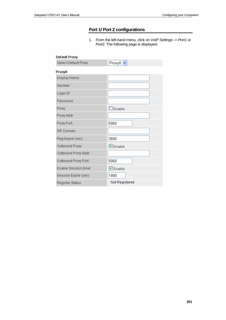
Satspeed V7621-A1 User’s Manual Configuring your Computers
201
Port 1/ Port 2 configurations
1. From the left-hand menu, click on VoIP Settings -> Port1 or Port2. The following page is displayed:

Satspeed V7621-A1 User’s Manual Configuring your Computers
202

Satspeed V7621-A1 User’s Manual Configuring your Computers
203

Satspeed V7621-A1 User’s Manual Configuring your Computers
204

Satspeed V7621-A1 User’s Manual Configuring your Computers
205

Satspeed V7621-A1 User’s Manual Configuring your Computers
206

Satspeed V7621-A1 User’s Manual Configuring your Computers
207
SIP Account
Set account for the port (lines) individually.
Option Description
Display Name Enter user name to be displayed.
Number Enter user name (or phone number) of the user.
Login ID Enter user name for authentication, maximum 39 characters.
Password Enter user password for authentication, maximum 39 characters.
Proxy Enable/Disable Proxy.
Default: Disable

Satspeed V7621-A1 User’s Manual Configuring your Computers
208
Option Description
Proxy Addr The IP address of SIP proxy
Proxy Port The port number used by SIP Proxy
Default: 5060
SIP Domain Assign domain name for the URL to be registered.
Reg Expire (sec)
SIP registration expired time. Assigns the time interval from 1 – 65535, default setting is 3600 seconds.
Outbound Proxy
Enable: All outgoing requests will be sent to this outbound proxy.
Default: Disabled
Outbound Proxy Addr
Specify the IP Address of SIP Outbound Proxy server.
This field contains the URI string or the IP of the outbound proxy.
Outbound Proxy Port
The port number of Outbound Proxy Server, assign a number from 1024 to 65535, default setting is 5060.
Register Status
The Status of Register

Satspeed V7621-A1 User’s Manual Configuring your Computers
209
SIP Advanced
Prompts for SIP Advanced Setting
Option Description
SIP Port Assign the SIP port number of terminal adapter. Its range is 1024 to 65535, default setting is 5060 for FX0 and 5061 for FXS1.
Media Port Enter the port for RTP Port number for initial of sending RTP packet. Its range is 1024 to 65535.
Default: 9000.
DMTF Relay DTMFs are the tones generated by your telephone's keypad. Select the DTMF relay method. ATA supports 4 methods:
SIP INFO
RFC 2833
In-band pass through mode
Default: In-band pass through mode.

Satspeed V7621-A1 User’s Manual Configuring your Computers
210
Option Description
RFC2833 Payload Type
Specify the Out-band 2833 payload type value.
Default: 96
SIP INFO Duration (ms)
The Duration (ms) SIP INFO
Call Waiting Enable/Disable Call Waiting.
Default: Enable
Call Waiting Caller ID
Enable/Disable Call Waiting Caller ID.
Default: Disable
Reject Direct IP Call
Enable/Disable Reject Direct IP Call.
Default: Disable
Forward Mode
Prompts for Call Forward Mode Setting
Option Description
Immediate Forward to
Enable/Disable Immediate Forward to.
Default: Disable
Immediate Number
Assigns a phone number; if you want all incoming calls of the port always be redirected.
Or You can specify a phone URI in this field. A URI look like SIP:[email protected] or SIP:PHONENUMBR@PROXYSERVER
Busy Forward to
Enable/Disable Busy Forward to.
Default: Disable
Busy Number When the port is busy, the incoming call will be redirected to the specified phone number.
Or You can specify a phone URI in this field. A URI look like SIP:[email protected] or SIP:PHONENUMBR@PROXYSERVER

Satspeed V7621-A1 User’s Manual Configuring your Computers
211
Option Description
No Answer Forward to
Enable/Disable No Answer Forward to.
Default: Disable
No Answer Number
When the port is no answer, the incoming call will be redirected to the specified phone number.
Or You can specify a phone URI in this field. A URI look like SIP:[email protected] or SIP:PHONENUMBR@PROXYSERVER
No Answer Time (sec)
When the phone is ring a long time, the incoming call will timeout and redirected to the specified phone number. Default setting is 0 seconds.
Speed Dial
Speed Dial lets you define a button or a set of buttons to link to a specific number defined in Speed Dial.
The speed dial is used to set up a list of telephone numbers and SIP addresses for the frequently called callee. In this list, a shorter number is assigned to the called party instead of original phone numbers or addresses. The module supports up to 10 speed dial numbers.

Satspeed V7621-A1 User’s Manual Configuring your Computers
212
Option Description
Position There are 10 Speed Dial number from 0 to 9.
Just pick up the phone and dial the speed dial number for example 5 and then dial # to make the call for the Phone Number in Speed dial number 5.
Name Enter the Name of the called party.
Phone Number
Assigns a phone number.
Or You can specify a phone URI in this field. A URI look like SIP:[email protected] or SIP:PHONENUMBR@PROXYSERVER
Select Delete a specified entry.
Abbreviated (Phonebook) Dial
In Abbreviated Dial (Phone Book) contains Speed Dial Settings. You can setup the Speed Dial number. If you want to use Speed Dial you just dial the speed dial number then press “#”.
You can add/delete Speed Dial number. You can input maximum 5 entries speed dial list.
If you need to add a phone number into the Speed Dial list, you need to input the Abbreviated Name (Speed Dial Number) and the phone number (by URL type). When you finished a new phone list, just click the “Apply” button.
Option Description
Abbreviated Name Enter the Speed Dial Number
Phone Number Enter the URL, VoIP Phone Number, Remote WAN IP Address of VoIP Gateway

Satspeed V7621-A1 User’s Manual Configuring your Computers
213
Examples
Example 1: Abbreviated Name: 001, Phone Number: 2222
When the user dials the Abbreviated Number 001, it will dial to the VoIP User whose phone number is 2222.
Example 2: Abbreviated Name: 002, Phone Number: 192.168.10.222
When the user dials the Number 002, it will dial to the VoIP Device whose WAN IP Address is 192.168.10.222.
Example 3: Abbreviated Name: 003, Phone Number: 192.168.10.222:5061
When the user dials the Number 003, it will dial to the VoIP Device whose WAN IP Address is 192.168.10.232 with the port 5061.
Example 4: Abbreviated Name: 004, Phone Number: [email protected]
When the user dials the Number 004, it will dial to the VoIP User test who registers to the SIP Server 192.168.10.101.
Be noted that you need also register to the then same SIP Server. If you register to the different SIP Server, please make sure that the SIP Server allows you dial to other SIP Server.

Satspeed V7621-A1 User’s Manual Configuring your Computers
214
Example 5: Abbreviated Name: 005, Phone Number: voipuser
When the user dials the Number 005, it will dial to the VoIP User whose phone number is voipuser.
Dial plan
Dial plan Configuration.
PSTN Routing Prefix
Base on the Routing rule to auto routing/dialing to PSTN
Codec
The Codec is used to compress the voice signal into data packets. Each Codec has different bandwidth requirement.
Option Description
Precedence The Codec is used to compress the voice signal into data packets. Each Codec has different bandwidth requirement. ATA supports 9 kinds of codec. To determine the priority, selects one codec algorithm from the check box individually.

Satspeed V7621-A1 User’s Manual Configuring your Computers
215
V.152
V.152 Configuration.
T.38(FAX)
The T.38 FAX procedure is used for the changeover from VoIP to fax mode during a call. The SIP will establish a normal VoIP call using INVITEs with SDP field to support T.38 detail.
T.38 is an ITU standard for sending fax communications across IP networks in a real-time mode. Fax messages are sent as UDP or TCP/IP packets. Choose this option can transfer FAX message and transfer FAX message with T.38.
Option Description
T.38 Enable/Disable T.38.
Default: Disable
T.38 Port Enter the port for T.38 Port number for initial of sending T.38 packet.
Fax Modem Detection
Mode
Enable/Disable FAX, Modem or AUTO detection mode.
Default: AUTO

Satspeed V7621-A1 User’s Manual Configuring your Computers
216
T.38(customize parameters)
T.38(customize parameters) Configuration.
Hot Line
Hot Line provides a way for a user to call a designated phone number without dialing any number. Once the user picks up the handset of the line which is setup as a “Hot Line”, the system will automatically dial the pre-set number and connect the caller to the pre-set place. For example, assuming that the station number 101 in the factory is set as hotline to Warehouse A.
Option Description
Use Hot Line Enable/Disable Use Hot Line.
Default: Disable
Hot Line Number
Enter the Hot Line Number.

Satspeed V7621-A1 User’s Manual Configuring your Computers
217
DND (Don't Disturb)
The Do Not Disturb function allows a caller to listen to a standard voicemail message, which simply states you are away from your desk or the office at this time. The caller is never aware that you have Do Not Disturb activated on your phone, so they will not be offended. You can later return the phone calls when it is more convenient for you.
Option Description
DND Mode Always/Enable/Disable DND Mode.
Always: When it was On. All incoming call will be blocked and the caller will hear the busy tone any time when place a call until disable this feature.
Default: Disable
From Input the start time of the time period. (24 hours format, hh:mm)
To Input the end time of the time period. (24 hours format, hh:mm)
Authentication
Once it was configured, you need to enter the Off-Hook Password to get the dial tone for dialing a phone number.
Example 1: Off-Hook Password: 1234
a. After you pick up the phone, the IVR will ask you to enter the password.
b. If you enter the correct Password, the IVR will ask you to dial the phone number to be reached.
c. If you enter the wrong password, the IVR will ask you again and again until you entered the correct one.
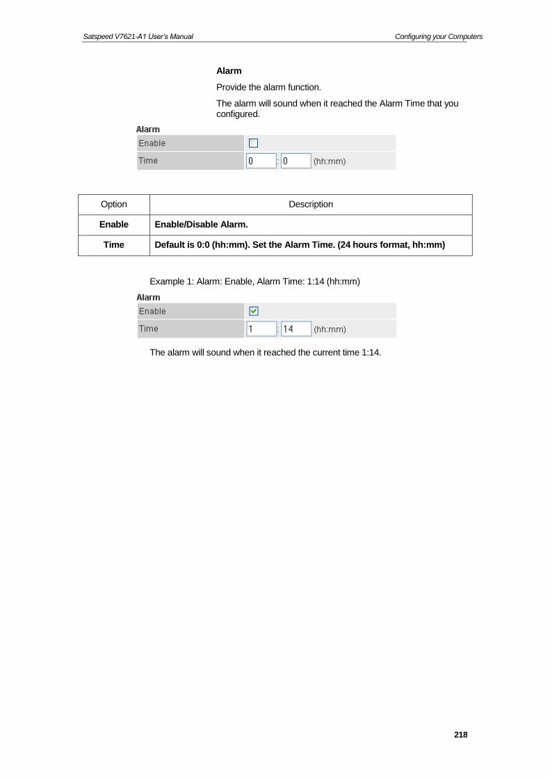
Satspeed V7621-A1 User’s Manual Configuring your Computers
218
Alarm
Provide the alarm function.
The alarm will sound when it reached the Alarm Time that you configured.
Option Description
Enable Enable/Disable Alarm.
Time Default is 0:0 (hh:mm). Set the Alarm Time. (24 hours format, hh:mm)
Example 1: Alarm: Enable, Alarm Time: 1:14 (hh:mm)
The alarm will sound when it reached the current time 1:14.

Satspeed V7621-A1 User’s Manual Configuring your Computers
219
DSP
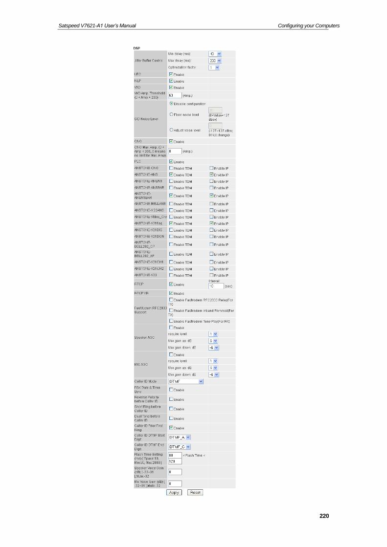
Satspeed V7621-A1 User’s Manual Configuring your Computers
220

Satspeed V7621-A1 User’s Manual Configuring your Computers
221
Option Description
Jitter Buffer Control
Min delay (ms): 40-100.
Max delay (ms): 130-300.
Optimization factor: 1-13
Vad Enable/Disable this function. There are three types of silence suppression:
Silence Suppression Enabled - NO CNG
Silence Suppression Enabled - Only G.711 Annex II type
Silence Suppression Enabled - Codec Specific CN.
Default: Disable.
Speaker AGC Set a specific sound intensity for receiving sound. Select a level from 1 to 9. The “gain” means increase in the power of electrical signal, measures by decibel.
MIC AGC Set a specific sound intensity for transmitting sound. Select a level from 1 to 9. The “gain” means increase in the power of electrical signal, measures by decibel.
Caller ID Mode
There are five Call ID modes:
FSK_BELLCORE: The Bellcore standard is used in United States, Australia, China, Hong Kong and Singapore. It uses the 1200 baud Bell 202 tone modulation and the first bit of data is transferred after receiving the first ring tone.
FSK_ETSI: The European Telecommunications -1 and -2, and ES 200 778-1 and -2, the latter replacing ETS 300 778-1 & -2) allows 3 physical transport layers (Bellcore, BT and CCA) combined with 2 data formats (MDMF & SDMF), plus the DTMF system and a no-ring mode for meter-reading and the like. It's more of a recognition that the different types exist than an attempt to define a single "standard".
FSK_BT: British Telecom developed their own standard, which wakes up the display with a line reversal, then sends the data as CCITT V23 modem tones in a format similar to MDMF. It is used by BT, wireless networks like the late Ionica, and some cable companies.
FSK_NTT: Japanese Caller ID
DTMF: DTMF is an example of a multi-frequency shift keying (MFSK) system. Today DTMF is used for most call setup to the telephone exchange, at least in developed regions of the world, and trunk signaling is now done out of band using the SS7 signaling system.
FSK Date & Time Sync
Enable/Disable this function.
Default: Disable.

Satspeed V7621-A1 User’s Manual Configuring your Computers
222
Option Description
Reverse Polarity
before Caller ID
Polarity Reversal is enabled to inform the charge/billing system.
Enable/Disable this function.
Default: Disable.
Short Ring before Caller
ID
Enable/Disable this function.
Default: Disable.
Dual Tone before Caller
ID
Enable/Disable this function.
Default: Disable.
Caller ID Prior First Ring
Enable/Disable this function.
Default: Enable.
Caller ID DTMF Start
Digit
There are four Caller ID DTMF Start Digit:
DTMF_A/ DTMF_B/DTMF_C/DTMF_D
Caller ID DTMF End
Digit
There are four Caller ID DTMF End Digit:
DTMF_A/ DTMF_B/DTMF_C/DTMF_D
Caller ID Soft FSK Gen
Enable/Disable this function.
Default: Enable.
Flash Time Setting (ms) [
Space:10, Min:30,
Max:2000 ]
Min: 30 < Flash Time < Max:900
Speaker Voice Gain (dB) [ -
32~31 ],Mute:-32
Configure the Speaker Voice Gain.
Mic Voice Gain (dB) [ -
32~31 ],Mute:-32
Configure the Mic Voice Gain.

Satspeed V7621-A1 User’s Manual Configuring your Computers
223
Tone Settings
This page is used to configure the parameters for tone settings.
1. From the left-hand menu, click on VoIP Settings -> Tone. The following page is displayed:

Satspeed V7621-A1 User’s Manual Configuring your Computers
224
Select Country
Wireless VoIP Gateway supports configuration of pre-configured audible tones based on the geographical location. Adjust the tone frequency according to each country.
Telephony developers working in VoIP, PBXs, VoIP gateways, phones, modems and other PSTN technologies that are developing products internationally have to know the varying international call progress tones that differ from country-to-country.
1. To prompts for Tone setting. Select a Country from the pull-down menu.
2. Click Apply.
Select Custom Tone and Tone Parameters
To custom the call progress tones, you should search on a specific call progress tone (e.g. dial tone, busy tone, call waiting tone..etc.) for their frequency, wavelength, period, amplitude, speed, and candence.
3. Select a Custom Tone from the pull-down menu. The following page is displayed:
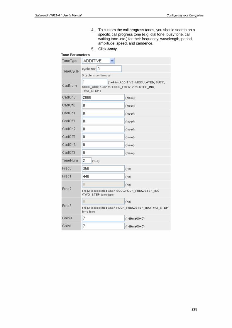
Satspeed V7621-A1 User’s Manual Configuring your Computers
225
4. To custom the call progress tones, you should search on a specific call progress tone (e.g. dial tone, busy tone, call waiting tone..etc.) for their frequency, wavelength, period, amplitude, speed, and candence.
5. Click Apply.

Satspeed V7621-A1 User’s Manual Configuring your Computers
226
Ring Settings
This page is used to configure the parameters for ring settings.
1. From the left-hand menu, click on VoIP Settings -> Ring. The following page is displayed:
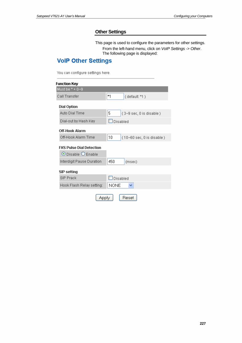
Satspeed V7621-A1 User’s Manual Configuring your Computers
227
Other Settings
This page is used to configure the parameters for other settings.
From the left-hand menu, click on VoIP Settings -> Other. The following page is displayed:

Satspeed V7621-A1 User’s Manual Configuring your Computers
228
Auto Provision Settings
This page is used to configure the parameters for Auto Provision and Firmware update.
2. From the left-hand menu, click on VoIP Settings -> Config. The following page is displayed:
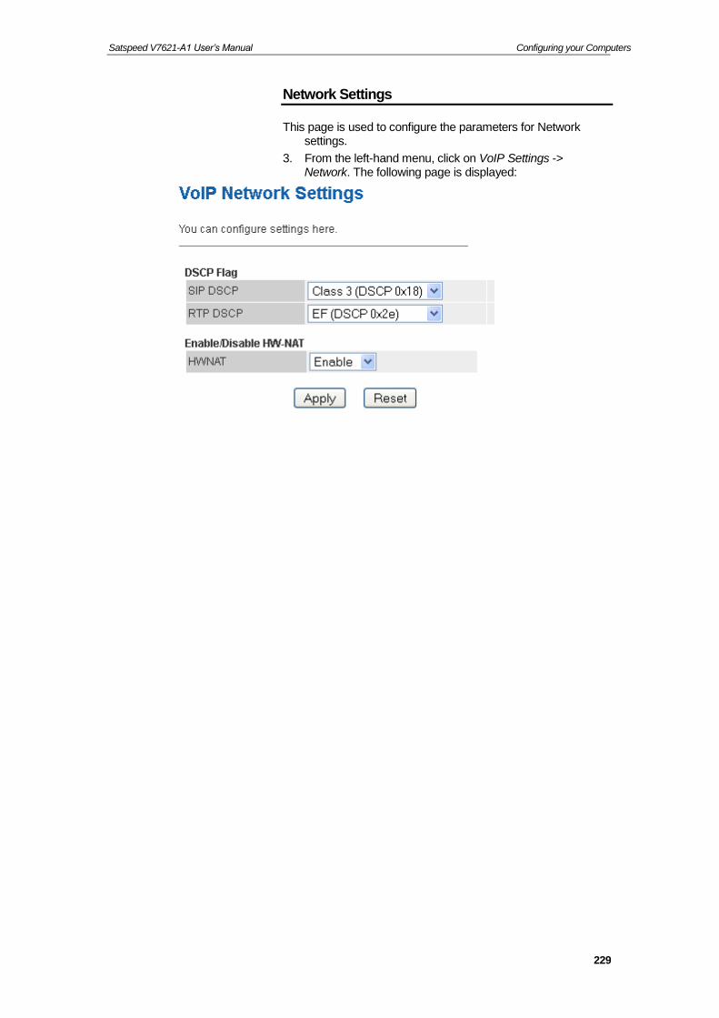
Satspeed V7621-A1 User’s Manual Configuring your Computers
229
Network Settings
This page is used to configure the parameters for Network settings.
3. From the left-hand menu, click on VoIP Settings -> Network. The following page is displayed:

Satspeed V7621-A1 User’s Manual Configuring your Computers
230
29 ARP Table
This ARP Table shows a list of learned MAC addresses.
ARP Table
4. From the left Advance menu, click on ARP Table.

Satspeed V7621-A1 User’s Manual Configuring your Computers
231
30 Bridging
You can enable/disable Spanning Tree Protocol and set MAC address aging time in this page.
Bridging
5. From the left Advance menu, click on Bridging.
Fields on the first setting block
Description
Ageing Time Set the Ethernet address ageing time, in seconds. After [Ageing Time] seconds of not having seen a frame coming from a certain address, the bridge will time out (delete) that address from Forwarding DataBase (fdb).
802.1d Spanning Tree
Enable/disable the spanning tree protocol
Function buttons
Description
Apply Changes Save this bridge configuration. New configuration will take effect after saving into flash memory and rebooting the system. See section “Admin” for details.
Show MACs List MAC address in forwarding table.

Satspeed V7621-A1 User’s Manual Configuring your Computers
232
31 Routing
The Routing page enables you to define specific route for your Internet and network data.
Most users do not need to define routes. On a typical small home or office LAN, the existing routes that set up the default gateways for your LAN hosts and for the DSL device provide the most appropriate path for all your Internet traffic.
−On your LAN hosts, a default gateway directs all Internet traffic to the LAN port(s) on the DSL device. Your LAN hosts know their default gateway either because you assigned it to them when you modified your TCP/IP properties, or because you configured them to receive the information dynamically from a server whenever they access the Internet.
−On the DSL device itself, a default gateway is defined to direct all outbound Internet traffic to a route at your ISP. The default gateway is assigned either automatically by your ISP whenever the device negotiates an Internet access, or manually by user to setup through the configuration.
You may need to define routes if your home setup includes two or more networks or subnets, if you connect to two or more ISP services, or if you connect to a remote corporate LAN.
Static Route
6. From the left Advance menu, click on Routing. The following page is displayed:

Satspeed V7621-A1 User’s Manual Configuring your Computers
233
Fields on the first setting block
Description
Enable Check to enable the selected route or route to be added.
Destination The network IP address of the subnet. The destination can be specified as the IP address of a subnet or a specific host in the subnet. It can also be specified as all zeros to indicate that this route should be used for all destinations for which no other route is defined (this is the route that creates the default gateway).
Subnet Mask The network mask of the destination subnet. The default gateway uses a mask of 0.0.0.0.
Next Hop The IP address of the next hop through which traffic will flow towards the destination subnet.
Metric Defines the number of hops between network nodes that data packets travel. The default value is 0, which means that the subnet is directly one hop away on the local LAN network.
Interface The WAN interface to which a static routing subnet is to be applied.
Function buttons
Description
Add Route Add a user-defined destination route.
Update Update the selected destination route on the Static Route Table.
Delete Selected Delete a selected destination route on the Static Route Table.
Show Routes Click this button to view the DSL device’s routing table. The IP Route Table displays, as shown in Figure.

Satspeed V7621-A1 User’s Manual Configuring your Computers
234
32 SNMP
Simple Network Management Protocol (SNMP) is a troubleshooting and management protocol that uses the UDP protocol on port 161 to communicate between clients and servers. The DSL device can be managed locally or remotely by SNMP protocol.
SNMP
7. From the left Advance menu, click on SNMP. The following page is displayed:

Satspeed V7621-A1 User’s Manual Configuring your Computers
235
Fields on the first setting block
Description
System Description
System description of the DSL device.
System Contact Contact person and/or contact information for the DSL device.
System Name An administratively assigned name for the DSL device.
System Location The physical location of the DSL device.
Trap IP Address Destination IP address of the SNMP trap.
Community name (read-only)
Name of the read-only community. This read-only community allows read operation to all objects in the MIB.
Community name (write-only)
Name of the write-only community. This write-only community allows write operation to the objects defines as read-writable in the MIB.
Function buttons
Description
Apply Changes Save SNMP configuration. New configuration will take effect after saving into flash memory and rebooting the system. See section “Admin” for details.
Reset Reset the configuration.

Satspeed V7621-A1 User’s Manual Configuring your Computers
236
33 IP QoS
Entries in this table are used to assign the precedence for each incoming packet based on specified policy.
Config Procedure:
1: set traffic rule.
2: assign the precedence or add marker for different stream.
QoS Policy
8. From the left Advance menu, click on IP QoS -> QoS Policy. The following page is displayed:

Satspeed V7621-A1 User’s Manual Configuring your Computers
237
9. Click on Enable. The following page is displayed:
This page is used to configure the QoS policy and Queue. If select PRIO of policy, the lower numbers imply greater precedence. If select WRR of policy, please input the weight of this queue. Default is 40:30:20:10. After configuration, please click 'Apply Changes'
QoS Classification
10. From the left Advance menu, click on IP QoS -> QoS Classification. The following page is displayed:
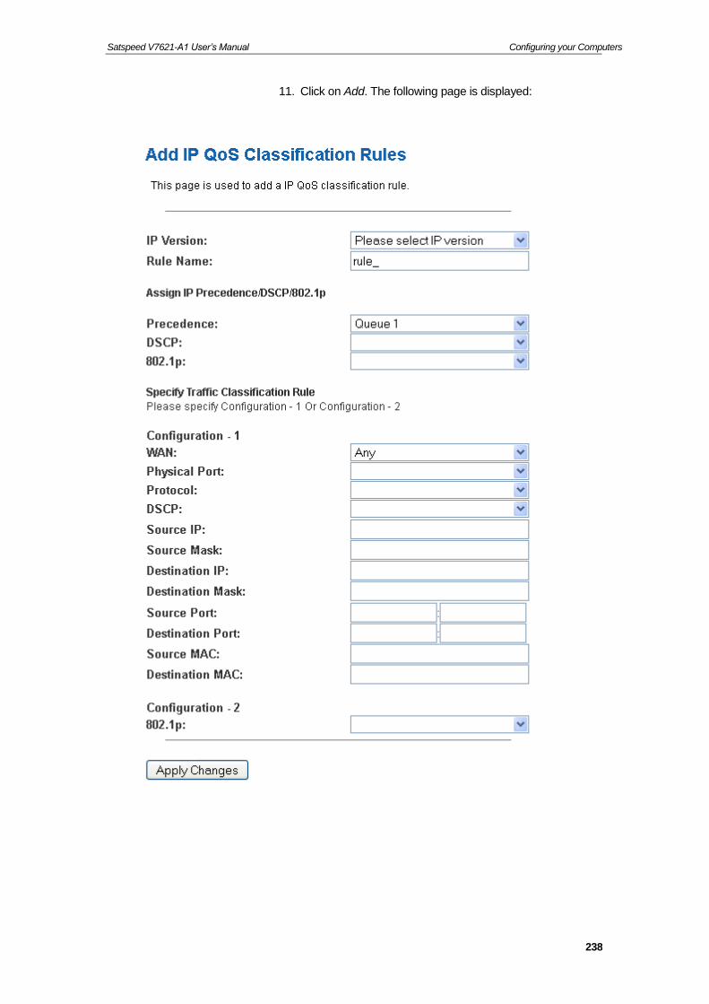
Satspeed V7621-A1 User’s Manual Configuring your Computers
238
11. Click on Add. The following page is displayed:

Satspeed V7621-A1 User’s Manual Configuring your Computers
239
Fields on the first setting block
Description
IP Version Select the IP Version
Rule Name Configure the Rule Name
Precedence Select this field to mark the IP precedence bits in the packet that match this classification rule.
DSCP Select the DSCP
802.1p Select this field to mark the 3-bit user-priority field in the 802.1p header of the packet that match this classification rule. Note that this 802.1p marking is workable on a given PVC channel only if the VLAN tag is enabled in this PVC channel.
WAN Select the WAN Interface
Physical Port The incoming ports. The selections include LAN ports, and the blank for not applicable.
Protocol The selections are TCP, UDP, ICMP and the blank for none. This field is required if the source port or destination port has been entered.
DSCP Select the DSCP
Source IP The IP address of the traffic source.
Source Netmask The source IP netmask. This field is required if the source IP has been entered.
Destination IP The IP address of the traffic destination.
Destination Netmask
The destination IP netmask. This field is required if the destination IP has been entered.
Source Port The source port of the selected protocol. You cannot configure this field without entering the protocol first.
Destination Port The destination port of the selected protocol. You cannot configure this field without entering the protocol first.
Source MAC The MAC of the traffic source.
Destination MAC The MAC of the traffic destination.
802.1p Select this field to mark the 3-bit user-priority field in the 802.1p header of the packet that match this classification rule. Note that this 802.1p marking is workable on a given PVC channel only if the VLAN tag is enabled in this PVC channel.
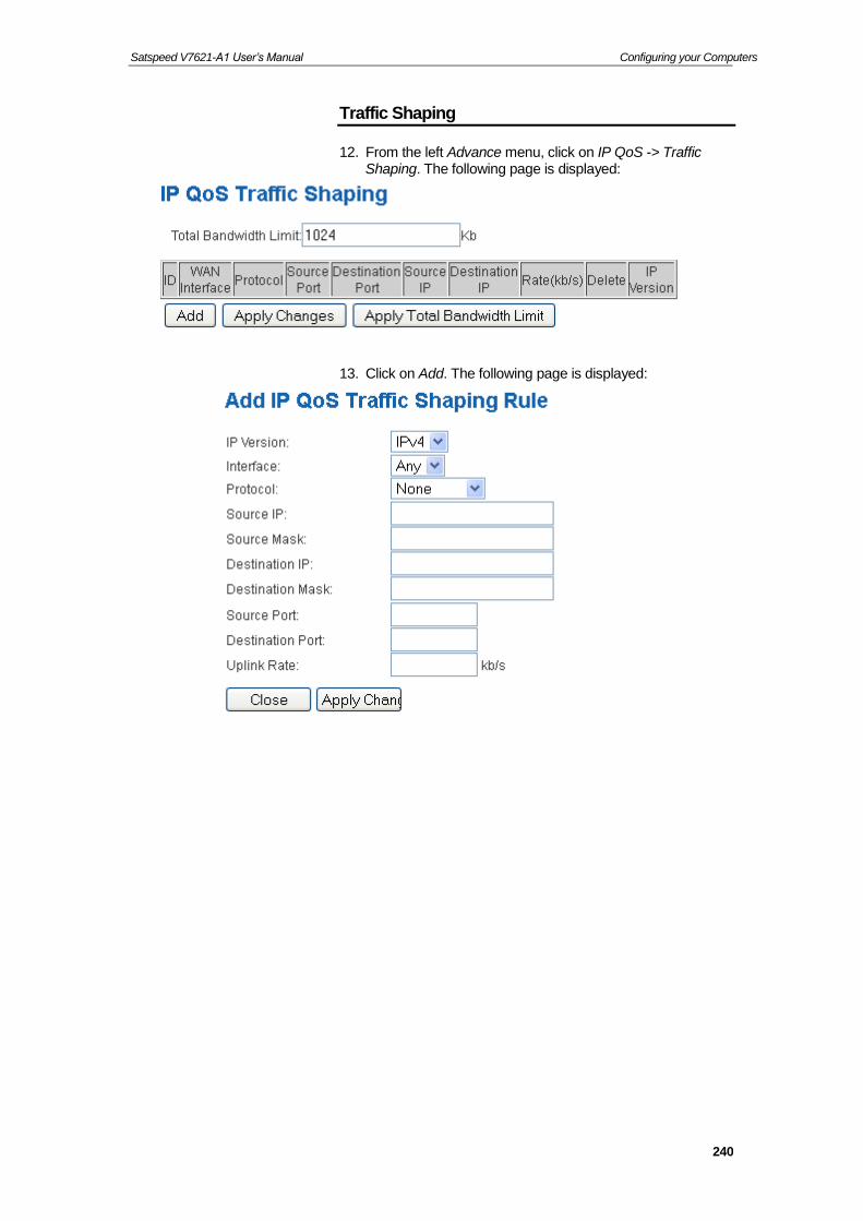
Satspeed V7621-A1 User’s Manual Configuring your Computers
240
Traffic Shaping
12. From the left Advance menu, click on IP QoS -> Traffic Shaping. The following page is displayed:
13. Click on Add. The following page is displayed:

Satspeed V7621-A1 User’s Manual Configuring your Computers
241
Fields on the first setting block
Description
IP Version Select the IP Version
Interface Select the Interface
Protocol The selections are TCP, UDP, ICMP and the blank for none. This field is required if the source port or destination port has been entered.
Source IP The IP address of the traffic source.
Source Mask The source IP netmask. This field is required if the source IP has been entered.
Destination IP The IP address of the traffic destination.
Destination Mask The destination IP netmask. This field is required if the destination IP has been entered.
Source Port The source port of the selected protocol. You cannot configure this field without entering the protocol first.
Destination Port The destination port of the selected protocol. You cannot configure this field without entering the protocol first.
Uplink Rate Configure the Uplink Rate

Satspeed V7621-A1 User’s Manual Configuring your Computers
242
34 Remote Access
This page is used to enable/disable management services for the LAN and WAN.
Remote Access
14. From the left Advance menu, click on Remote Access. The following page is displayed:

Satspeed V7621-A1 User’s Manual Configuring your Computers
243
35 Others
Here you can set some other advanced settings.
Others
15. From the left Advance menu, click on Others. The following page is displayed:
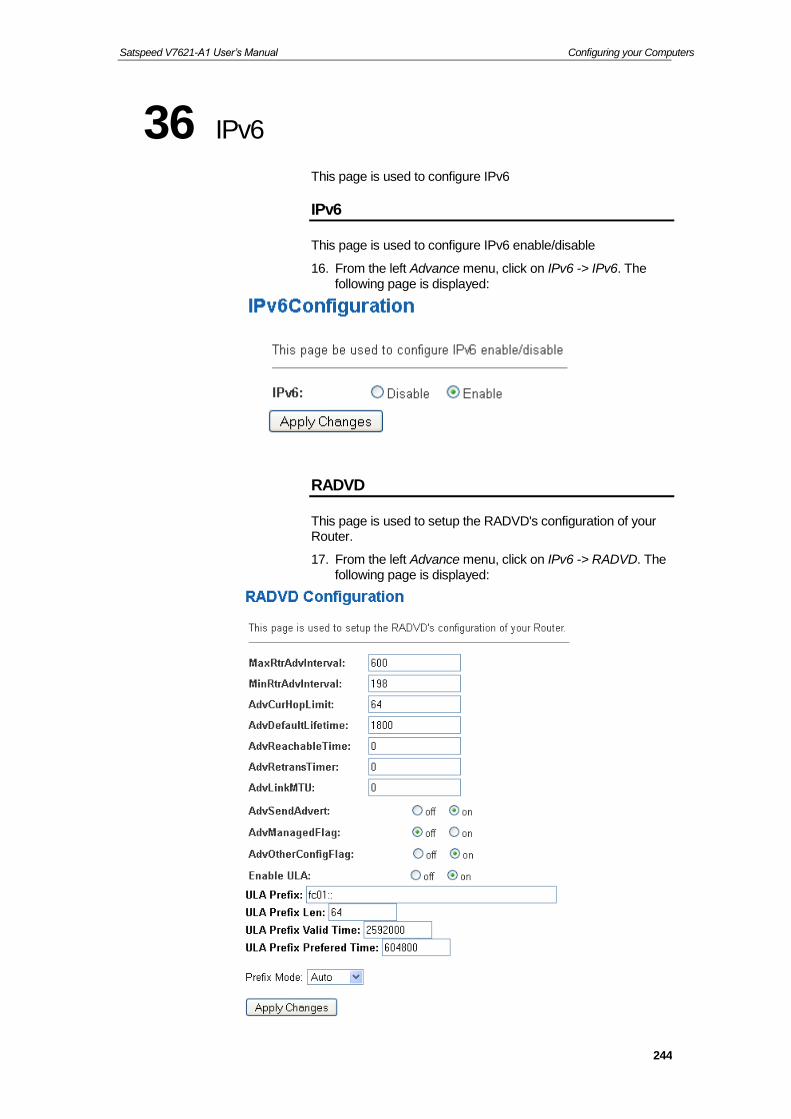
Satspeed V7621-A1 User’s Manual Configuring your Computers
244
36 IPv6
This page is used to configure IPv6
IPv6
This page is used to configure IPv6 enable/disable
16. From the left Advance menu, click on IPv6 -> IPv6. The following page is displayed:
RADVD
This page is used to setup the RADVD's configuration of your Router.
17. From the left Advance menu, click on IPv6 -> RADVD. The following page is displayed:

Satspeed V7621-A1 User’s Manual Configuring your Computers
245
DHCPv6
This page is used to configure DHCPv6 Server and DHCPv6 Relay.
18. From the left Advance menu, click on IPv6 -> DHCPv6. The following page is displayed:
MLD Proxy
This page is used to configure MLD Proxy.
19. From the left Advance menu, click on IPv6 -> MLD Proxy.
Fields on the first setting block
Description
MLD Proxy Enable/disable the MLD Proxy
WAN Interface Select a WAN Interface
Function buttons
Description
Apply Changes Save this bridge configuration. New configuration will take effect after saving into flash memory and rebooting the system. See section “Admin” for details.

Satspeed V7621-A1 User’s Manual Configuring your Computers
246
20. Click OK button.
MLD Snooping
This page is used to configure MLD Snooping.
21. From the left Advance menu, click on IPv6 -> MLD Snooping.
22. Click OK button.
Fields on the first setting block
Description
MLD Snooping Enable/disable the MLD Snooping
Function buttons
Description
Apply Changes Save this bridge configuration. New configuration will take effect after saving into flash memory and rebooting the system. See section “Admin” for details.

Satspeed V7621-A1 User’s Manual Configuring your Computers
247
IPv6 Routing
This page is used to configure the IPv6 static routing information. Here you can add/delete static IP routes.
23. From the left Advance menu, click on IPv6 -> IPv6 Routing.

Satspeed V7621-A1 User’s Manual Configuring your Computers
248
IP/Port Filtering
Entries in this table are used to restrict certain types of data packets through the Gateway. Use of such filters can be helpful in securing or restricting your local network.
24. From the left Advance menu, click on IPv6 -> IP/Port Filtering.

Satspeed V7621-A1 User’s Manual Configuring your Computers
249
37 Diagnostic
The DSL device supports some useful diagnostic tools.
Ping
Once you have your DSL device configured, it is a good idea to make sure you can ping the network. A ping command sends a message to the host you specify. If the host receives the message, it sends messages in reply. To use it, you must know the IP address of the host you are trying to communicate with and enter the IP address in the Host Address field. Click Go! To start the ping command, the ping result will then be shown in this page.
25. From the left Maintenance menu, click on Diagnostic -> Ping. The following page is displayed:
26. Type the IP Address in the Host field.
27. Click Ping
Fields Description
Host Address The IP address you want to ping.
Function buttons
Description
Go! To start the ping command

Satspeed V7621-A1 User’s Manual Configuring your Computers
250
28. Now you could see the result below:
ATM Loopback
In order to isolate the ATM interface problems, you can use ATM OAM loopback cells to verify connectivity between VP/VC endpoints, as well as segment endpoints within the VP/VC. ATM uses F4 and F5 cell flows as follows:
−F4: used in VPs
−F5: used in VCs
An ATM connection consists of a group of points. This OAM implementation provides management for the following points:
−Connection endpoint: the end of a VP/VC connection where the ATM cell are terminated
−Segment endpoint: the end of a connection segment
This page allows you to use ATM ping, which generates F5 segment and end-to-end loop-back cells to test the reachability of a segment endpoint or a connection endpoint.
29. From the left Maintenance menu, click on Diagnostic -> ATM Loopback. The following page is displayed:

Satspeed V7621-A1 User’s Manual Configuring your Computers
251
DSL Tone Diagnostics
This page displays the DSL Tone Diagnostic performance. Click Start button to start the DSL diagnostic.
30. From the left Maintenance menu, click on Diagnostic -> DSL Tone. The following page is displayed:
31. Click Start button to start the DSL diagnostic.
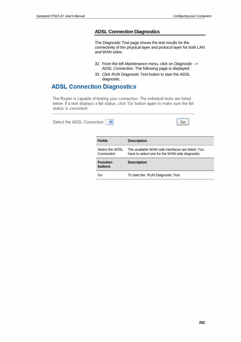
Satspeed V7621-A1 User’s Manual Configuring your Computers
252
ADSL Connection Diagnostics
The Diagnostic Test page shows the test results for the connectivity of the physical layer and protocol layer for both LAN and WAN sides.
32. From the left Maintenance menu, click on Diagnostic -> ADSL Connection. The following page is displayed:
33. Click RUN Diagnostic Test button to start the ADSL diagnostic.
Fields Description
Select the ADSL Connection
The available WAN side interfaces are listed. You have to select one for the WAN side diagnostic.
Function buttons
Description
Go To start the RUN Diagnostic Test

Satspeed V7621-A1 User’s Manual Configuring your Computers
253
38 Commit/Reboot
Whenever you use the web console to change system settings, the changes are initially placed in temporary storage. To save your changes for future use, you can use the Commit/Reboot function. This function saves your changes from RAM to flash memory and reboot the system.
IMPORTANT! Do not turn off your modem or press the Reset button while this procedure is in progress.
Commit and Reboot
34. From the left Admin menu, click on Commit/Reboot. The following page is displayed:
35. Click on Commit and Reboot.
36. Click on OK.
37. System rebooting, Please wait ... 60 seconds.

Satspeed V7621-A1 User’s Manual Configuring your Computers
254
39 Backup/Restore
You can save the current configuration of your Router to a file on your computer. This is highly recommended before you change any configuration settings on the Router or before you upgrade your firmware.
Backup settings
38. From the left Maintenance menu, click on Admin -> Backup/Restore. The following page is displayed:
Figure 5: Backup & Restore page
39. Click on Save.
40. Choose the Save option and select a suitable location and filename to save your backup file to.
41. Press Save

Satspeed V7621-A1 User’s Manual Configuring your Computers
255
Restore settings
42. From the left Maintenance menu, click on Update -> Backup/Restore. The following page is displayed:
43. Click Browse... and browse to the location of your backup file
44. Click Upload
Figure 6: Backup & Restore page
45. Restore settings from config file successful!.
46. The System is Restarting ...
Resetting to Defaults
This page allows you to reset your device to its default factory settings.
The configuration settings of your device are stored in a configuration file. When you set up your device and access the web pages for the very first time, the configuration file contains a default factory configuration..
If you do make changes to the default configuration but then wish to revert back to the original factory configuration, you can do so by resetting the device to factory defaults.
Note
If you reset your device to factory defaults, all previous configuration changes that you have made are overwritten by the factory default configuration.

Satspeed V7621-A1 User’s Manual Configuring your Computers
256
Software Reset:
47. From the left Admin menu, click on Commit/Reboot. The following page is displayed:
48. Click on Reset.
49. Click on OK.
50. System rebooting, Please wait ... 60 seconds.

Satspeed V7621-A1 User’s Manual Configuring your Computers
257
40 System Log
This page can be used to set remote log server and show the system log.
System Log
51. From the left-hand Admin menu, click on System Log. The following page is displayed:
Option Description
Enable Log Enable/Disable the feature.
Default: Disable
Log Level Select one Log Level
Display Level Select one Display Level
Mode Select one Mode
Enable Remote Log
Enable: Send the system log to remote log server. To do this, make sure a secure syslog server is available. Default: Disable
Log Server IP Address
Enter the IP Address of remote log server.
Server UDP Port
Enter the UDP Port of remote log server.
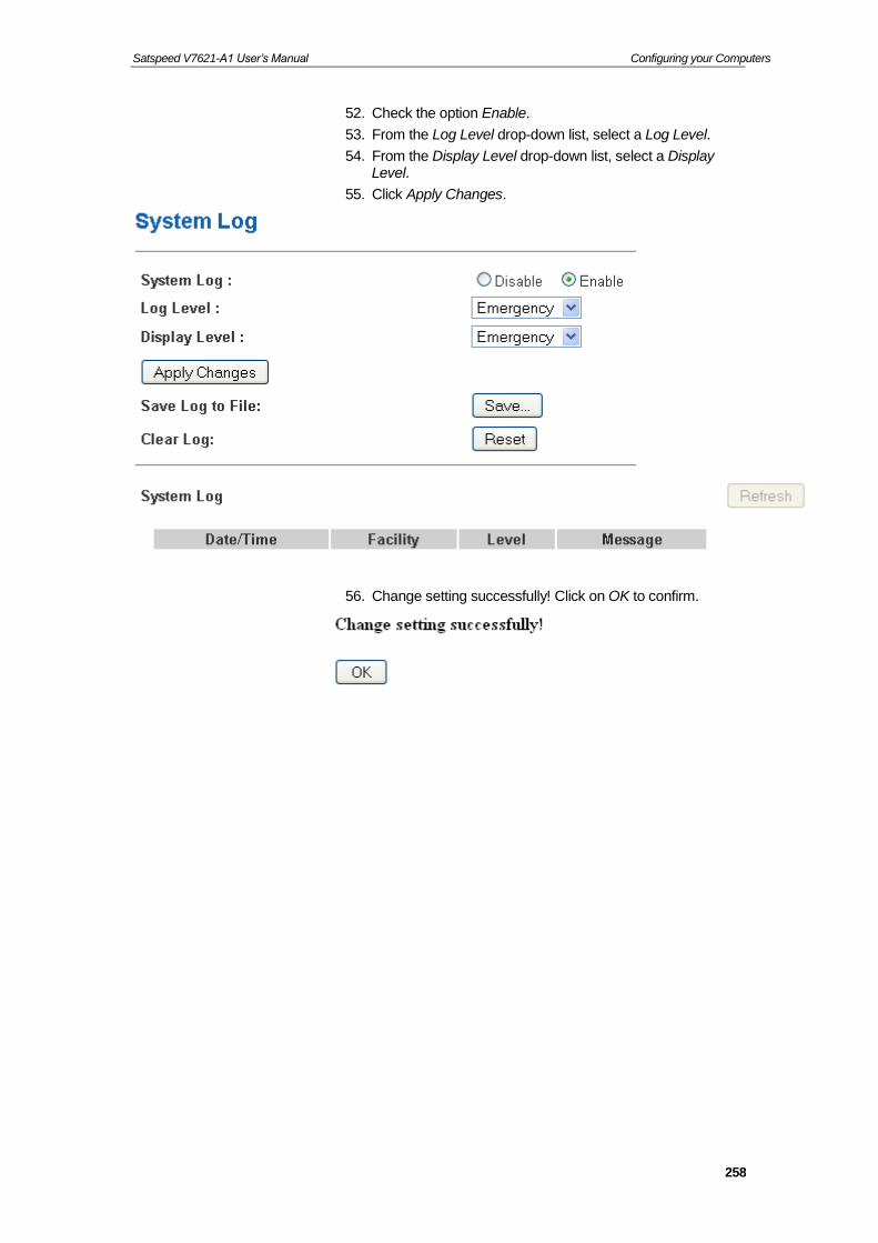
Satspeed V7621-A1 User’s Manual Configuring your Computers
258
52. Check the option Enable.
53. From the Log Level drop-down list, select a Log Level.
54. From the Display Level drop-down list, select a Display Level.
55. Click Apply Changes.
56. Change setting successfully! Click on OK to confirm.

Satspeed V7621-A1 User’s Manual Configuring your Computers
259
41 Password
You can restrict access to your device’s web pages using password protection. With password protection enabled, users must enter a username and password before gaining access to the web pages.
By default, password protection is enabled on your device, and the username and password set are as follows:
Username: admin
Password: admin
Username: user
Password: user
Setting your username and password
Note
Non-authorized users may try to access your system by guessing your username and password. We recommend that you change the default username and password to your own unique settings.
To change the default password:
57. From the left Admin menu, click on Password. The following page is displayed:
Figure 7: Currently Defined Administration Password: Setup page

Satspeed V7621-A1 User’s Manual Configuring your Computers
260
58. This page displays the current username and password settings. Change your own unique password in the relevant boxes. They can be any combination of letters or numbers with a maximum of 30 characters. The default setting uses admin for the username and admin for password.
59. If you are happy with these settings, click Apply Changes. You will see following page that the new user has been displayed on the Currently Defined Users. You need to login to the web pages using your new username and new password.
Figure 8: Administration Password
60. Click OK.
61. Enter User name and new Password.
62. Click OK.

Satspeed V7621-A1 User’s Manual Configuring your Computers
261
42 Firmware Update
The Firmware Update page allows you to:
manually download the latest firmware version from website and manually update your firmware. See Manually updating firmware.
About firmware versions
Firmware is a software program. It is stored as read-only memory on your device.
Your device can check whether there are later firmware versions available. If there is a later version, you can download it via the Internet and install it on your device.
Note
If there is a firmware update available you are strongly advised to install it on your device to ensure that you take full advantage of any new feature developments.
Manually updating firmware
You can manually download the latest firmware version from website to your PC’s file directory.
Once you have downloaded the latest firmware version to your PC, you can manually select and install it as follows:
63. From the left Admin menu, click on Firmware Upgrade. The following page is displayed:
64. Click on the Browse… button.
Figure 9: Manual Update Installation section
(Note that if you are using certain browsers (such as Opera 7) the Browse button is labeled Choose.)

Satspeed V7621-A1 User’s Manual Configuring your Computers
262
65. Use the Choose file box to navigate to the relevant directory where the firmware version is saved.
66. Once you have selected the file to be installed, click Open. The file’s directory path is displayed in the Select File: text box.
67. Click Upload. The device checks that the selected file contains an updated version of firmware. A screen pops up, please click OK.
68. Firmware upgrading, Please wait …. 250 seconds.
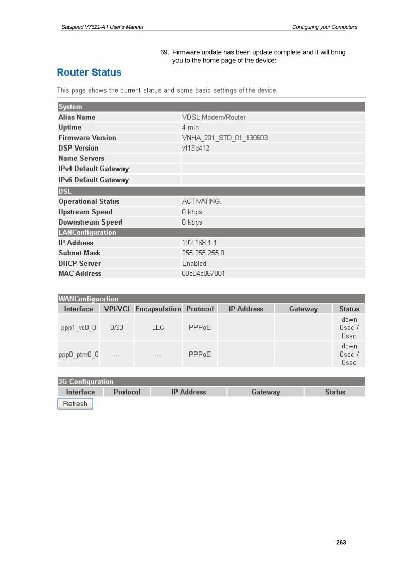
Satspeed V7621-A1 User’s Manual Configuring your Computers
263
69. Firmware update has been update complete and it will bring you to the home page of the device:

Satspeed V7621-A1 User’s Manual Configuring your Computers
264
70. From the left Admin menu, click on Commit/Reboot. The following page is displayed:
71. Click on Reset.
72. Click on OK.
73. System rebooting, Please wait ... 60 seconds.

Satspeed V7621-A1 User’s Manual Configuring your Computers
265
43 ACL Configuration
You can specify which services are accessable form LAN or WAN side.
Entries in this ACL table are used to permit certain types of data packets from your local network or Internet network to the Gateway.
Using of such access control can be helpful in securing or restricting the Gateway management.
ACL Config
74. From the left Firewall menu, click on ACL. The following page is displayed:
Figure 10: ACL Configuration page

Satspeed V7621-A1 User’s Manual Configuring your Computers
266
44 Time Zone
Certain systems may not have a date or time mechanism or may be using inaccurate time/day information. the Simple Network Time Protocol feature provides a way to synchronize the device’s own time of day setting with a remote time server as described in RFC 2030 (SNTP) and RFC 1305 (NTP).
SNTP Server and SNTP Client Configuration settings
75. From the left Maintenance menu, click on Time. The following page is displayed:

Satspeed V7621-A1 User’s Manual Configuring your Computers
267
76. Select proper Time Zone from Time Zone Select drop-down list.
77. Check on Enable SNTP Client Update.
78. Add NTP Server using IP Address.
79. Click on Apply Changes.
Figure 11: SNTP Server Configuration page
80. Click on OK.
Fields Description
Current Time The current time of the specified time zone. You can set the current time by yourself or configured by SNTP.
Interval The Interval of SNTP client to update the system clock
Time Zone Select
The time zone in which the DSL device resides.
SNTP server The IP address or the host name of the SNTP server. You can select from the list or set it manually.
Function Button Description
Apply Changes Click to save the setting of default actions to the configuration.

Satspeed V7621-A1 User’s Manual Configuring your Computers
268
Time
Zone
GMT +/-
offset
Description Daylight Saving Start
Daylight Saving End
IDLW -1200 International Date Line West Not applicable Not applicable
NT -1100 Nome Not applicable Not applicable
HST -1000 Hawaii Standard Not applicable Not applicable
AKST -900 Alaska Standard First Sunday of April at 2:00am
Last Sunday of October at 2:00am
YST -900 Yukon Standard First Sunday of April at 2:00am
Last Sunday of October at 2:00am
PST -800 US Pacific Standard First Sunday of April at 2:00am
Last Sunday of October at 2:00am
MST -700 US Mountain Standard First Sunday of April at 2:00am
Last Sunday of October at 2:00am
CST -600 US Central Standard First Sunday of April at 2:00am
Last Sunday of October at 2:00am
EST -500 US Eastern Standard First Sunday of April at 2:00am
Last Sunday of October at 2:00am
AST -400 Atlantic Standard First Sunday of April at 2:00am
Last Sunday of October at 2:00am
NFST -330 Newfoundland Standard First Sunday of April at 2:00am
Last Sunday of October at 2:00am
NFT -330 Newfoundland First Sunday of April at 2:00am
Last Sunday of October at 2:00am
BRA -300 Brazil Standard First Sunday of February at 2:00 am
Third Sunday of February at 2:00am
AT -200 Azores Not applicable Not applicable
WAT -100 West Africa Last Sunday March at 1:00am
Last Sunday October at 1:00am
GMT +000 Greenwich Mean Last Sunday March at 1:00am
Last Sunday October at 1:00am
UTC +000 Universal (Coordinated) Last Sunday March at 1:00am
Last Sunday October at 1:00am
WET +000 Western European Last Sunday March at 1:00am
Last Sunday October at 1:00am

Satspeed V7621-A1 User’s Manual Configuring your Computers
269
Time
Zone
GMT +/-
offset
Description Daylight Saving Start
Daylight Saving End
CET +100 Central European Last Sunday March at 2:00am
Last Sunday October at 2:00am
MET
+100 Middle European Last Sunday March at 2:00am
Last Sunday October at 2:00am
MEWT +100 Middle European Winter Last Sunday March at 2:00am
Last Sunday October at 2:00am
SWT +100 Swedish Winter Last Sunday March at 2:00am
Last Sunday October at 2:00am
BST +100 British Summer Last Sunday March at 2:00am
Last Sunday October at 2:00am
EET +200 Eastern Europe, Russia Zone 1
Last Sunday March at 2:00am
Last Sunday October at 2:00am
FST +200 French Summer Last Sunday March at 2:00am
Last Sunday October at 2:00am
MEST +200 Middle European Summer Last Sunday March at 2:00am
Last Sunday October at 2:00am
SST +200 Swedish Summer Last Sunday March at 2:00am
Last Sunday October at 2:00am
IST +200 Israeli Standard First Friday April at 2:00am
First Friday September at 2:00am
IDT +300 Israeli Daylight 1st April at 2:00am First Friday of September at 2:00am
BT +300 Baghdad 1st April at 2:00am 1st October at 2:00am
IT +330 Iran 21st March 23rd September
USZ3 +400 Russian Volga Last Sunday March at 2:00am
Last Sunday in October at 2:00am
USZ4 +500 Russian Ural Last Sunday of March at 2:00am
Last Sunday October at 2:00am
INST +530 Indian Standard Not applicable Not applicable
USZ5 +600 Russian West-Siberian Last Sunday March at 2:00am
Last Sunday October at 2:00am
NST +630 North Sumatra Not applicable Not applicable
WAST +700 West Australian Standard Not applicable Not applicable
USZ6 +700 Russia Yenisei Last Sunday March at 2:00am
Last Sunday October at 2:00am
JT +730 Java Not applicable Not applicable
CCT +800 China Coast Not applicable Not applicable
ROK +900 Korean Standard Not applicable Not applicable

Satspeed V7621-A1 User’s Manual Configuring your Computers
270
Time
Zone
GMT +/-
offset
Description Daylight Saving Start
Daylight Saving End
KST +900 Korean Standard Not applicable Not applicable
JST +900 Japan Standard Not applicable Not applicable
CAST +930 Central Australian Standard Last Sunday October at 2:00am
Last Sunday March at 2:00am
KDT +1000 Korean Daylight Not applicable Not applicable
EAST +1000 Eastern Australian Standard Last Sunday October at 2:00am
Last Sunday March at 3:00am
GST +1000 Guam Standard Last Sunday March at 2:00am
Last Sunday October at 2:00am
CADT +1030 Central Australian Daylight Last Sunday October at 2:00am
Last Sunday March at 3:00am
IDLE +1200 International Date Line East Not applicable Not applicable
NZST +1200 New Zealand Standard Last Sunday October at 2:00am
Last Sunday March at 2:00am
NZT +1200 New Zealand Last Sunday October at 2:00am
Last Sunday March at 2:00am
Time Zone abbreviations

Satspeed V7621-A1 User’s Manual Configuring your Computers
271
45 TR-069
TR-069 is a protocol for communication between a CPE and Auto-Configuration Server (ACS). The CPE TR-069 configuration should be well defined to be able to communicate with the remote ACS.
TR-069 Configuration
81. From the left Admin menu, click on TR-069. The following page is displayed:

Satspeed V7621-A1 User’s Manual Configuring your Computers
272
Figure 12: TR-069 Configuration page
ACS Field Description
URL ACS URL. For example, http://10.0.0.1:80
https://10.0.0.1:443
User Name The username the DSL device should use when connecting to the ACS.
Password The password the DSL device should use when connecting to the ACS.
Periodic Inform When this field is enabled, the DSL device will send an Inform RPC to the ACS server at the system startup, and will continue to send it periodically at an interval defined in Periodic Inform Interval field; When this
field is disabled, the DSL device will only send Inform RPC to the ACS server once at the system startup.
Periodic Inform Interval
Time interval in second to send Inform RPC.
Connection Request Field
Description
User Name The username the remote ACS should use when connecting to this device.
Password The password the remote ACS should use when connecting to this device.
Path The path of the device ConnectionRequestURL. The device ConnectionRequestURL should be configured based on the Device_IP, Path and Port as follows:
http://Device_IP:Port/Path
Port The port of the device ConnectionRequestURL.
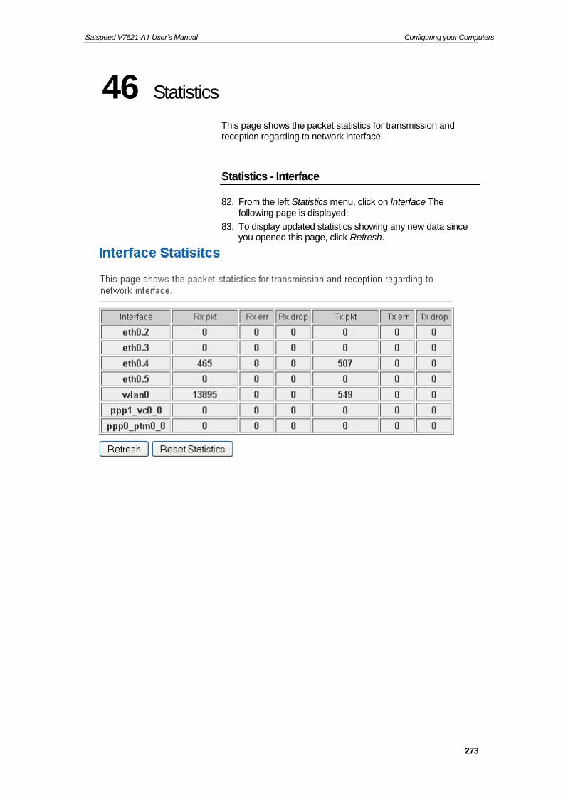
Satspeed V7621-A1 User’s Manual Configuring your Computers
273
46 Statistics
This page shows the packet statistics for transmission and reception regarding to network interface.
Statistics - Interface
82. From the left Statistics menu, click on Interface The following page is displayed:
83. To display updated statistics showing any new data since you opened this page, click Refresh.

Satspeed V7621-A1 User’s Manual Configuring your Computers
274
Statistics - DSL
This page shows the packet statistics for transmission and reception regarding to network interface.
84. From the left Statistics menu, click on DSL The following page is displayed:
85. To display updated statistics showing any new data since you opened this page, click Refresh.
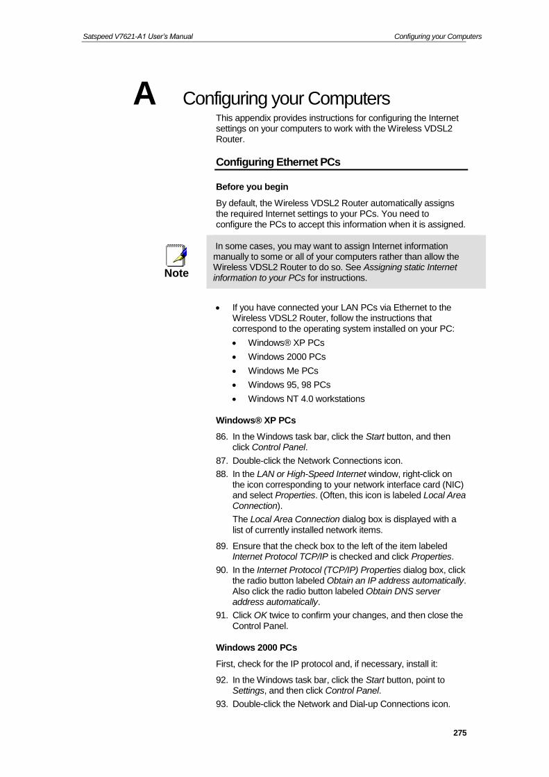
Satspeed V7621-A1 User’s Manual Configuring your Computers
275
A Configuring your Computers This appendix provides instructions for configuring the Internet settings on your computers to work with the Wireless VDSL2 Router.
Configuring Ethernet PCs
Before you begin
By default, the Wireless VDSL2 Router automatically assigns the required Internet settings to your PCs. You need to configure the PCs to accept this information when it is assigned.
Note
In some cases, you may want to assign Internet information manually to some or all of your computers rather than allow the Wireless VDSL2 Router to do so. See Assigning static Internet information to your PCs for instructions.
If you have connected your LAN PCs via Ethernet to the
Wireless VDSL2 Router, follow the instructions that correspond to the operating system installed on your PC:
Windows® XP PCs
Windows 2000 PCs
Windows Me PCs
Windows 95, 98 PCs
Windows NT 4.0 workstations
Windows® XP PCs
86. In the Windows task bar, click the Start button, and then click Control Panel.
87. Double-click the Network Connections icon.
88. In the LAN or High-Speed Internet window, right-click on the icon corresponding to your network interface card (NIC) and select Properties. (Often, this icon is labeled Local Area Connection).
The Local Area Connection dialog box is displayed with a list of currently installed network items.
89. Ensure that the check box to the left of the item labeled Internet Protocol TCP/IP is checked and click Properties.
90. In the Internet Protocol (TCP/IP) Properties dialog box, click the radio button labeled Obtain an IP address automatically. Also click the radio button labeled Obtain DNS server address automatically.
91. Click OK twice to confirm your changes, and then close the Control Panel.
Windows 2000 PCs
First, check for the IP protocol and, if necessary, install it:
92. In the Windows task bar, click the Start button, point to Settings, and then click Control Panel.
93. Double-click the Network and Dial-up Connections icon.

Satspeed V7621-A1 User’s Manual Configuring your Computers
276
94. In the Network and Dial-up Connections window, right-click the Local Area Connection icon, and then select Properties.
The Local Area Connection Properties dialog box is displayed with a list of currently installed network components. If the list includes Internet Protocol (TCP/IP), then the protocol has already been enabled. Skip to step 10.
95. If Internet Protocol (TCP/IP) does not display as an installed component, click Install…
96. In the Select Network Component Type dialog box, select Protocol, and then click Add…
97. Select Internet Protocol (TCP/IP) in the Network Protocols list, and then click OK.
You may be prompted to install files from your Windows 2000 installation CD or other media. Follow the instructions to install the files.
98. If prompted, click OK to restart your computer with the new settings.
Next, configure the PCs to accept IP information assigned by the Wireless VDSL2 Router:
99. In the Control Panel, double-click the Network and Dial-up Connections icon.
100. In the Network and Dial-up Connections window, right-click the Local Area Connection icon, and then select Properties.
101. In the Local Area Connection Properties dialog box, select Internet Protocol (TCP/IP), and then click Properties.
102. In the Internet Protocol (TCP/IP) Properties dialog box, click the radio button labeled Obtain an IP address automatically. Also click the radio button labeled Obtain DNS server address automatically.
103. Click OK twice to confirm and save your changes, and then close the Control Panel.

Satspeed V7621-A1 User’s Manual Configuring your Computers
277
Windows Me PCs
104. In the Windows task bar, click the Start button, point to Settings, and then click Control Panel.
105. Double-click the Network and Dial-up Connections icon.
106. In the Network and Dial-up Connections window, right-click the Network icon, and then select Properties.
The Network Properties dialog box displays with a list of currently installed network components. If the list includes Internet Protocol (TCP/IP), then the protocol has already been enabled. Skip to step 11.
107. If Internet Protocol (TCP/IP) does not display as an installed component, click Add…
108. In the Select Network Component Type dialog box, select Protocol, and then click Add…
109. Select Microsoft in the Manufacturers box.
110. Select Internet Protocol (TCP/IP) in the Network Protocols list, and then click OK.
You may be prompted to install files from your Windows Me installation CD or other media. Follow the instructions to install the files.
111. If prompted, click OK to restart your computer with the new settings.
Next, configure the PCs to accept IP information assigned by the Wireless VDSL2 Router:
112. In the Control Panel, double-click the Network and Dial-up Connections icon.
113. In Network and Dial-up Connections window, right-click the Network icon, and then select Properties.
114. In the Network Properties dialog box, select TCP/IP, and then click Properties.
115. In the TCP/IP Settings dialog box, click the radio button labeled Server assigned IP address. Also click the radio button labeled Server assigned name server address.
116. Click OK twice to confirm and save your changes, and then close the Control Panel.
Windows 95, 98 PCs
First, check for the IP protocol and, if necessary, install it:
117. In the Windows task bar, click the Start button, point to Settings, and then click Control Panel.
118. Double-click the Network icon.
The Network dialog box displays with a list of currently installed network components. If the list includes TCP/IP, and then the protocol has already been enabled. Skip to step 9.
119. If TCP/IP does not display as an installed component, click Add…
The Select Network Component Type dialog box displays.
120. Select Protocol, and then click Add…
The Select Network Protocol dialog box displays.

Satspeed V7621-A1 User’s Manual Configuring your Computers
278
121. Click on Microsoft in the Manufacturers list box, and then click TCP/IP in the Network Protocols list box.
122. Click OK to return to the Network dialog box, and then click OK again.
You may be prompted to install files from your Windows 95/98 installation CD. Follow the instructions to install the files.
123. Click OK to restart the PC and complete the TCP/IP installation.
Next, configure the PCs to accept IP information assigned by the Wireless VDSL2 Router:
124. Open the Control Panel window, and then click the Network icon.
125. Select the network component labeled TCP/IP, and then click Properties.
If you have multiple TCP/IP listings, select the listing associated with your network card or adapter.
126. In the TCP/IP Properties dialog box, click the IP Address tab.
127. Click the radio button labeled Obtain an IP address automatically.
128. Click the DNS Configuration tab, and then click the radio button labeled Obtain an IP address automatically.
129. Click OK twice to confirm and save your changes.
You will be prompted to restart Windows.
130. Click Yes.
Windows NT 4.0 workstations
First, check for the IP protocol and, if necessary, install it:
131. In the Windows NT task bar, click the Start button, point to Settings, and then click Control Panel.
132. In the Control Panel window, double click the Network icon.
133. In the Network dialog box, click the Protocols tab.
The Protocols tab displays a list of currently installed network protocols. If the list includes TCP/IP, then the protocol has already been enabled. Skip to step 9.
134. If TCP/IP does not display as an installed component, click Add…
135. In the Select Network Protocol dialog box, select TCP/IP, and then click OK.
You may be prompted to install files from your Windows NT installation CD or other media. Follow the instructions to install the files.
After all files are installed, a window displays to inform you that a TCP/IP service called DHCP can be set up to dynamically assign IP information.
136. Click Yes to continue, and then click OK if prompted to restart your computer.
Next, configure the PCs to accept IP information assigned by the Wireless VDSL2 Router:

Satspeed V7621-A1 User’s Manual Configuring your Computers
279
137. Open the Control Panel window, and then double-click the Network icon.
138. In the Network dialog box, click the Protocols tab.
139. In the Protocols tab, select TCP/IP, and then click Properties.
140. In the Microsoft TCP/IP Properties dialog box, click the radio button labeled Obtain an IP address from a DHCP server.
141. Click OK twice to confirm and save your changes, and then close the Control Panel.
Assigning static Internet information to your PCs
If you are a typical user, you will not need to assign static Internet information to your LAN PCs because your ISP automatically assigns this information for you.
In some cases however, you may want to assign Internet information to some or all of your PCs directly (often called “statically”), rather than allowing the Wireless VDSL2 Router to assign it. This option may be desirable (but not required) if:
You have obtained one or more public IP addresses that you want to always associate with specific computers (for example, if you are using a computer as a public web server).
You maintain different subnets on your LAN (subnets are described in Appendix B).
Before you begin, you must have the following information available:
The IP address and subnet mask of each PC
The IP address of the default gateway for your LAN. In most cases, this is the address assigned to the LAN port on the Wireless VDSL2 Router. By default, the LAN port is assigned the IP address 192.168.1.1. (You can change this number or another number can be assigned by your ISP. See Addressing for more information.)
The IP address of your ISP’s Domain Name System (DNS) server.
On each PC to which you want to assign static information, follow the instructions relating only to checking for and/or installing the IP protocol. Once it is installed, continue to follow the instructions for displaying each of the Internet Protocol (TCP/IP) properties. Instead of enabling dynamic assignment of the IP addresses for the computer, DNS server and default gateway, click the radio buttons that enable you to enter the information manually.
Note
Your PCs must have IP addresses that place them in the same subnet as the Wireless VDSL2 Router’s LAN port. If you manually assign IP information to all your LAN PCs, you can follow the instructions in Addressing to change the LAN port IP address accordingly.
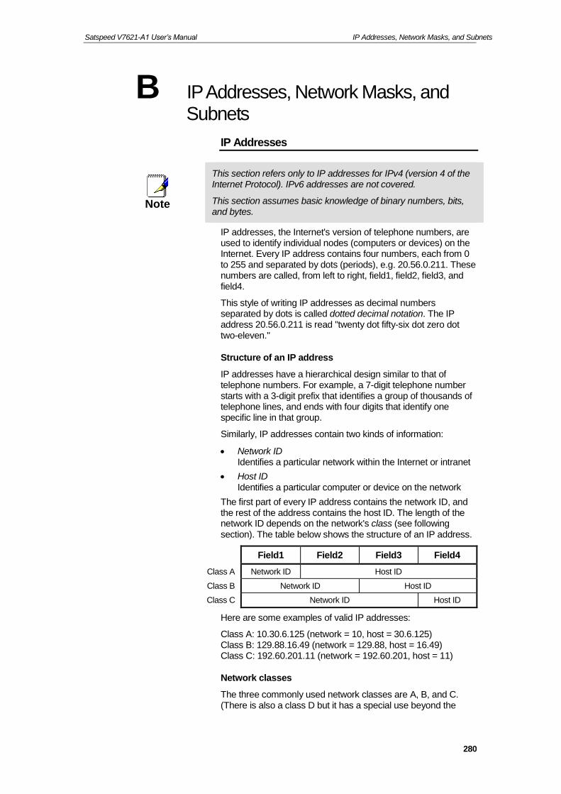
Satspeed V7621-A1 User’s Manual IP Addresses, Network Masks, and Subnets
280
B IP Addresses, Network Masks, and Subnets
IP Addresses
Note
This section refers only to IP addresses for IPv4 (version 4 of the Internet Protocol). IPv6 addresses are not covered.
This section assumes basic knowledge of binary numbers, bits, and bytes.
IP addresses, the Internet's version of telephone numbers, are used to identify individual nodes (computers or devices) on the Internet. Every IP address contains four numbers, each from 0 to 255 and separated by dots (periods), e.g. 20.56.0.211. These numbers are called, from left to right, field1, field2, field3, and field4.
This style of writing IP addresses as decimal numbers separated by dots is called dotted decimal notation. The IP address 20.56.0.211 is read "twenty dot fifty-six dot zero dot two-eleven."
Structure of an IP address
IP addresses have a hierarchical design similar to that of telephone numbers. For example, a 7-digit telephone number starts with a 3-digit prefix that identifies a group of thousands of telephone lines, and ends with four digits that identify one specific line in that group.
Similarly, IP addresses contain two kinds of information:
Network ID Identifies a particular network within the Internet or intranet
Host ID Identifies a particular computer or device on the network
The first part of every IP address contains the network ID, and the rest of the address contains the host ID. The length of the network ID depends on the network's class (see following section). The table below shows the structure of an IP address.
Field1 Field2 Field3 Field4
Class A Network ID Host ID
Class B Network ID Host ID
Class C Network ID Host ID
Here are some examples of valid IP addresses:
Class A: 10.30.6.125 (network = 10, host = 30.6.125) Class B: 129.88.16.49 (network = 129.88, host = 16.49) Class C: 192.60.201.11 (network = 192.60.201, host = 11)
Network classes
The three commonly used network classes are A, B, and C. (There is also a class D but it has a special use beyond the

Satspeed V7621-A1 User’s Manual IP Addresses, Network Masks, and Subnets
281
scope of this discussion.) These classes have different uses and characteristics.
Class A networks are the Internet's largest networks, each with room for over 16 million hosts. Up to 126 of these huge networks can exist, for a total of over 2 billion hosts. Because of their huge size, these networks are used for WANs and by organizations at the infrastructure level of the Internet, such as your ISP.
Class B networks are smaller but still quite large, each able to hold over 65,000 hosts. There can be up to 16,384 class B networks in existence. A class B network might be appropriate for a large organization such as a business or government agency.
Class C networks are the smallest, only able to hold 254 hosts at most, but the total possible number of class C networks exceeds 2 million (2,097,152 to be exact). LANs connected to the Internet are usually class C networks.
Some important notes regarding IP addresses:
The class can be determined easily from field1: field1 = 1-126: Class A field1 = 128-191: Class B field1 = 192-223: Class C (field1 values not shown are reserved for special uses)
A host ID can have any value except all fields set to 0 or all fields set to 255, as those values are reserved for special uses.
Subnet masks
Definition
mask
A mask looks like a regular IP address, but contains a pattern of bits that tells what parts of an IP address are the network ID and what parts are the host ID: bits set to 1 mean "this bit is part of the network ID" and bits set to 0 mean "this bit is part of the host ID."
Subnet masks are used to define subnets (what you get after dividing a network into smaller pieces). A subnet's network ID is created by "borrowing" one or more bits from the host ID portion of the address. The subnet mask identifies these host ID bits.
For example, consider a class C network 192.168.1. To split this into two subnets, you would use the subnet mask:
255.255.255.128
It's easier to see what's happening if we write this in binary:
11111111. 11111111. 11111111.10000000
As with any class C address, all of the bits in field1 through field3 are part of the network ID, but note how the mask specifies that the first bit in field4 is also included. Since this extra bit has only two values (0 and 1), this means there are two subnets. Each subnet uses the remaining 7 bits in field4 for its host IDs, which range from 1 to 126 hosts (instead of the usual 0 to 255 for a class C address).
Similarly, to split a class C network into four subnets, the mask is:

Satspeed V7621-A1 User’s Manual IP Addresses, Network Masks, and Subnets
282
255.255.255.192 or 11111111. 11111111. 11111111.11000000
The two extra bits in field4 can have four values (00, 01, 10, 11), so there are four subnets. Each subnet uses the remaining six bits in field4 for its host IDs, ranging from 1 to 62.
Note
Sometimes a subnet mask does not specify any additional network ID bits, and thus no subnets. Such a mask is called a default subnet mask. These masks are:
Class A: 255.0.0.0 Class B: 255.255.0.0 Class C: 255.255.255.0
These are called default because they are used when a network is initially configured, at which time it has no subnets.

User’s Guide Troubleshooting
C Troubleshooting This appendix suggests solutions for problems you may encounter in installing or using the Wireless VDSL2 Router, and provides instructions for using several IP utilities to diagnose problems.
Contact Customer Support if these suggestions do not resolve the problem.
Troubleshooting Suggestions
Problem Troubleshooting Suggestion
LEDs
Power LED does not illuminate after product is turned on.
Verify that you are using the power cable provided with the device and that it is securely connected to the Wireless VDSL2 Router and a wall socket/power strip.
Internet LED does not illuminate after phone cable is attached.
Verify that a standard telephone cable (called an RJ-11 cable) like the one provided is securely connected to the DSL port and your wall phone port. Allow about 30 seconds for the device to negotiate a connection with your ISP.
LINK LAN LED does not illuminate after Ethernet cable is attached.
Verify that the Ethernet cable is securely connected to your LAN hub or PC and to the Wireless VDSL2 Router. Make sure the PC and/or hub is turned on. Verify that your cable is sufficient for your network requirements. A 100 Mbit/sec network (10BaseTx) should use cables labeled CAT 5. A 10Mbit/sec network may tolerate lower quality cables.
Internet Access
My PC cannot access the Internet
Use the ping utility (discussed in the following section) to check whether your PC can communicate with the device’s LAN IP address (by default 192.168.1.1). If it cannot, check the Ethernet cabling. If you statically assigned a private IP address to the computer, (not a registered public address), verify the following:
Check that the gateway IP address on the computer is your public IP address (see Current Status for instructions on viewing the IP information.) If it is not, correct the address or configure the PC to receive IP information automatically.
Verify with your ISP that the DNS server specified for the PC is valid. Correct the address or configure the PC to receive this information automatically.

Satspeed V7621-A1 User’s Manual Troubleshooting
284
Problem Troubleshooting Suggestion
My LAN PCs cannot display web pages on the Internet.
Verify that the DNS server IP address specified on the PCs is correct for your ISP, as discussed in the item above. If you specified that the DNS server be assigned dynamically from a server, then verify with your ISP that the address configured on the Wireless VDSL2 Router is correct, then You can use the ping utility, to test connectivity with your ISP’s DNS server.
Web pages
I forgot/lost my user ID or password.
If you have not changed the password from the default, try using “admin” the user ID and “admin “ as password. Otherwise, you can reset the device to the default configuration by pressing the Reset Default button on the Rare panel of the device (see Rare Panel). Then, type the default User ID and password shown above. WARNING:
Resetting the device removes any custom settings and returns all settings to their default values.
I cannot access the web pages from my browser.
Use the ping utility, discussed in the following section, to check whether your PC can communicate with the device’s LAN IP address (by default 192.168.1.1). If it cannot, check the Ethernet cabling.
Verify that you are using your Browser
Verify that the PC’s IP address is defined as being on the same subnet as the IP address assigned to the LAN port on the Wireless VDSL2 Router.
My changes to the web pages are not being retained.
Be sure to use the Confirm Changes/Apply function after any changes.

Satspeed V7621-A1 User’s Manual Troubleshooting
285
Diagnosing Problem using IP Utilities
ping
Ping is a command you can use to check whether your PC can recognize other computers on your network and the Internet. A ping command sends a message to the computer you specify. If the computer receives the message, it sends messages in reply. To use it, you must know the IP address of the computer with which you are trying to communicate.
On Windows-based computers, you can execute a ping command from the Start menu. Click the Start button, and then click Run. In the Open text box, type a statement such as the following:
ping 192.168.1.1
Click OK. You can substitute any private IP address on your LAN or a public IP address for an Internet site, if known.
If the target computer receives the message, a Command Prompt window is displayed:
Figure 13: Using the ping Utility
If the target computer cannot be located, you will receive the message Request timed out.
Using the ping command, you can test whether the path to the Wireless VDSL2 Router is working (using the preconfigured default LAN IP address 192.168.1.1) or another address you assigned.
You can also test whether access to the Internet is working by typing an external address, such as that for www.yahoo.com (216.115.108.243). If you do not know the IP address of a particular Internet location, you can use the nslookup command, as explained in the following section.
From most other IP-enabled operating systems, you can execute the same command at a command prompt or through a system administration utility.

Satspeed V7621-A1 User’s Manual Troubleshooting
286
nslookup
You can use the nslookup command to determine the IP address associated with an Internet site name. You specify the common name, and the nslookup command looks up the name in on your DNS server (usually located with your ISP). If that name is not an entry in your ISP’s DNS table, the request is then referred to another higher-level server, and so on, until the entry is found. The server then returns the associated IP address.
On Windows-based computers, you can execute the nslookup command from the Start menu. Click the Start button, and then click Run. In the Open text box, type the following:
Nslookup
Click OK. A Command Prompt window displays with a bracket prompt (>). At the prompt, type the name of the Internet address that you are interested in, such as www.microsoft.com.
The window will display the associate IP address, if known, as shown below:
Figure 14: Using the nslookup Utility
There may be several addresses associated with an Internet name. This is common for web sites that receive heavy traffic; they use multiple, redundant servers to carry the same information.
To exit from the nslookup utility, type exit and press [Enter] at the command prompt.
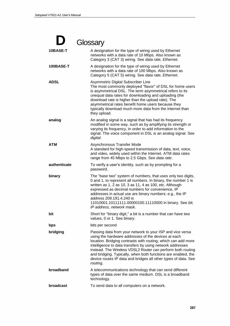
Satspeed V7621-A1 User’s Manual
287
D Glossary 10BASE-T A designation for the type of wiring used by Ethernet
networks with a data rate of 10 Mbps. Also known as Category 3 (CAT 3) wiring. See data rate, Ethernet.
100BASE-T A designation for the type of wiring used by Ethernet networks with a data rate of 100 Mbps. Also known as Category 5 (CAT 5) wiring. See data rate, Ethernet.
ADSL Asymmetric Digital Subscriber Line The most commonly deployed "flavor" of DSL for home users is asymmetrical DSL. The term asymmetrical refers to its unequal data rates for downloading and uploading (the download rate is higher than the upload rate). The asymmetrical rates benefit home users because they typically download much more data from the Internet than they upload.
analog An analog signal is a signal that has had its frequency modified in some way, such as by amplifying its strength or varying its frequency, in order to add information to the signal. The voice component in DSL is an analog signal. See digital.
ATM Asynchronous Transfer Mode A standard for high-speed transmission of data, text, voice, and video, widely used within the Internet. ATM data rates range from 45 Mbps to 2.5 Gbps. See data rate.
authenticate To verify a user’s identity, such as by prompting for a password.
binary The "base two" system of numbers, that uses only two digits, 0 and 1, to represent all numbers. In binary, the number 1 is written as 1, 2 as 10, 3 as 11, 4 as 100, etc. Although expressed as decimal numbers for convenience, IP addresses in actual use are binary numbers; e.g., the IP address 209.191.4.240 is 11010001.10111111.00000100.11110000 in binary. See bit, IP address, network mask.
bit Short for "binary digit," a bit is a number that can have two values, 0 or 1. See binary.
bps bits per second
bridging Passing data from your network to your ISP and vice versa using the hardware addresses of the devices at each location. Bridging contrasts with routing, which can add more intelligence to data transfers by using network addresses instead. The Wireless VDSL2 Router can perform both routing and bridging. Typically, when both functions are enabled, the device routes IP data and bridges all other types of data. See routing.
broadband A telecommunications technology that can send different types of data over the same medium. DSL is a broadband technology.
broadcast To send data to all computers on a network.

Satspeed V7621-A1 User’s Manual
288
DHCP Dynamic Host Configuration Protocol DHCP automates address assignment and management. When a computer connects to the LAN, DHCP assigns it an IP address from a shared pool of IP addresses; after a specified time limit, DHCP returns the address to the pool.
DHCP relay Dynamic Host Configuration Protocol relay A DHCP relay is a computer that forwards DHCP data between computers that request IP addresses and the DHCP server that assigns the addresses. Each of the Wireless VDSL2 Router's interfaces can be configured as a DHCP relay. See DHCP.
DHCP server Dynamic Host Configuration Protocol server A DHCP server is a computer that is responsible for assigning IP addresses to the computers on a LAN. See DHCP.
digital Of data, having a form based on discrete values expressed as binary numbers (0's and 1's). The data component in DSL is a digital signal. See analog.
DNS Domain Name System The DNS maps domain names into IP addresses. DNS information is distributed hierarchically throughout the Internet among computers called DNS servers. For example, www.yahoo.com is the domain name associated with IP address 216.115.108.243. When you start to access a web site, a DNS server looks up the requested domain name to find its corresponding IP address. If the DNS server cannot find the IP address, it communicates with higher-level DNS servers to determine the IP address. See domain name.
domain name A domain name is a user-friendly name used in place of its associated IP address. Domain names must be unique; their assignment is controlled by the Internet Corporation for Assigned Names and Numbers (ICANN). Domain names are a key element of URLs, which identify a specific file at a web site. See DNS.
download To transfer data in the downstream direction, i.e., from the Internet to the user.
DSL Digital Subscriber Line A technology that allows both digital data and analog voice signals to travel over existing copper telephone lines.
encryption keys See network keys
Ethernet The most commonly installed computer network technology, usually using twisted pair wiring. Ethernet data rates are 10 Mbps and 100 Mbps. See also 10BASE-T, 100BASE-T, twisted pair.
FTP File Transfer Protocol A program used to transfer files between computers connected to the Internet. Common uses include uploading new or updated files to a web server, and downloading files from a web server.
Gbps Abbreviation of Gigabits per second, or one billion bits per second. Internet data rates are often expressed in Gbps.
host A device (usually a computer) connected to a network.

Satspeed V7621-A1 User’s Manual
289
HTTP Hyper-Text Transfer Protocol HTTP is the main protocol used to transfer data from web sites so that it can be displayed by web browsers. See web browser, web site.
Hub A hub is a place of convergence where data arrives from one or more directions and is forwarded out in one or more directions. It connects an Ethernet bridge/Router to a group of PCs on a LAN and allows communication to pass between the networked devices.
ICMP Internet Control Message Protocol An Internet protocol used to report errors and other network-related information. The ping command makes use of ICMP.
IEEE The Institute of Electrical and Electronics Engineers is a technical professional society that fosters the development of standards that often become national and international standards.
Internet The global collection of interconnected networks used for both private and business communications.
intranet A private, company-internal network that looks like part of the Internet (users access information using web browsers), but is accessible only by employees.
IP See TCP/IP.
IP address Internet Protocol address The address of a host (computer) on the Internet, consisting of four numbers, each from 0 to 255, separated by periods, e.g., 209.191.4.240. An IP address consists of a network ID that identifies the particular network the host belongs to, and a host ID uniquely identifying the host itself on that network. A network mask is used to define the network ID and the host ID. Because IP addresses are difficult to remember, they usually have an associated domain name that can be specified instead. See domain name, network mask.
ISP Internet Service Provider A company that provides Internet access to its customers, usually for a fee.
LAN Local Area Network A network limited to a small geographic area, such as a home or small office.
LED Light Emitting Diode An electronic light-emitting device. The indicator lights on the front of the Wireless VDSL2 Router are LEDs.
MAC address Media Access Control address The permanent hardware address of a device, assigned by its manufacturer. MAC addresses are expressed as six pairs of hex characters, with each pair separated by colons. For example; NN:NN:NN:NN:NN:NN.
mask See network mask.
Mbps Abbreviation for Megabits per second, or one million bits per second. Network data rates are often expressed in Mbps.
NAT Network Address Translation A service performed by many Routers that translates your network’s publicly known IP address into a private IP address for each computer on your LAN. Only your Router and your

Satspeed V7621-A1 User’s Manual
290
LAN know these addresses; the outside world sees only the public IP address when talking to a computer on your LAN.
network A group of computers that are connected together, allowing them to communicate with each other and share resources, such as software, files, etc. A network can be small, such as a LAN, or very large, such as the Internet.
network mask A network mask is a sequence of bits applied to an IP address to select the network ID while ignoring the host ID. Bits set to 1 mean "select this bit" while bits set to 0 mean "ignore this bit." For example, if the network mask 255.255.255.0 is applied to the IP address 100.10.50.1, the network ID is 100.10.50, and the host ID is 1. See binary, IP address, subnet.
NIC Network Interface Card An adapter card that plugs into your computer and provides the physical interface to your network cabling. For Ethernet NICs this is typically an RJ-45 connector. See Ethernet, RJ-45.
packet Data transmitted on a network consists of units called packets. Each packet contains a payload (the data), plus overhead information such as where it came from (source address) and where it should go (destination address).
ping Packet Internet (or Inter-Network) Groper A program used to verify whether the host associated with an IP address is online. It can also be used to reveal the IP address for a given domain name.
port A physical access point to a device such as a computer or Router, through which data flows into and out of the device.
PPP Point-to-Point Protocol A protocol for serial data transmission that is used to carry IP (and other protocol) data between your ISP and your computer. The WAN interface on the Wireless VDSL2 Router uses two forms of PPP called PPPoA and PPPoE. See PPPoA, PPPoE.
PPPoA Point-to-Point Protocol over ATM One of the two types of PPP interfaces you can define for a Virtual Circuit (VC), the other type being PPPoE. You can define only one PPPoA interface per VC.
PPPoE Point-to-Point Protocol over Ethernet One of the two types of PPP interfaces you can define for a Virtual Circuit (VC), the other type being PPPoA. You can define one or more PPPoE interfaces per VC.
protocol A set of rules governing the transmission of data. In order for a data transmission to work, both ends of the connection have to follow the rules of the protocol.
remote In a physically separate location. For example, an employee away on travel who logs in to the company’s intranet is a remote user.
RIP Routing Information Protocol The original TCP/IP routing protocol. There are two versions of RIP: version I and version II.
RJ-11 Registered Jack Standard-11 The standard plug used to connect telephones, fax

Satspeed V7621-A1 User’s Manual
291
machines, modems, etc. to a telephone port. It is a 6-pin connector usually containing four wires.
RJ-45 Registered Jack Standard-45 The 8-pin plug used in transmitting data over phone lines. Ethernet cabling usually uses this type of connector.
routing Forwarding data between your network and the Internet on the most efficient route, based on the data’s destination IP address and current network conditions. A device that performs routing is called a Router.
SDNS Secondary Domain Name System (server) A DNS server that can be used if the primary DSN server is not available. See DNS.
subnet A subnet is a portion of a network. The subnet is distinguished from the larger network by a subnet mask that selects some of the computers of the network and excludes all others. The subnet's computers remain physically connected to the rest of the parent network, but they are treated as though they were on a separate network. See network mask.
subnet mask A mask that defines a subnet. See network mask.
TCP See TCP/IP.
TCP/IP Transmission Control Protocol/Internet Protocol The basic protocols used on the Internet. TCP is responsible for dividing data up into packets for delivery and reassembling them at the destination, while IP is responsible for delivering the packets from source to destination. When TCP and IP are bundled with higher-level applications such as HTTP, FTP, Telnet, etc., TCP/IP refers to this whole suite of protocols.
Telnet An interactive, character-based program used to access a remote computer. While HTTP (the web protocol) and FTP only allow you to download files from a remote computer, Telnet allows you to log into and use a computer from a remote location.
TFTP Trivial File Transfer Protocol A protocol for file transfers, TFTP is easier to use than File Transfer Protocol (FTP) but not as capable or secure.
TKIP Temporal Key Integrity Protocol (TKIP) provides WPA with a data encryption function. It ensures that a unique master key is generated for each packet, supports message integrity and sequencing rules and supports re-keying mechanisms.
triggers Triggers are used to deal with application protocols that create separate sessions. Some applications, such as NetMeeting, open secondary connections during normal operations, for example, a connection to a server is established using one port, but data transfers are performed on a separate connection. A trigger tells the device to expect these secondary sessions and how to handle them.
Once you set a trigger, the embedded IP address of each incoming packet is replaced by the correct host address so that NAT can translate packets to the correct destination. You can specify whether you want to carry out address replacement, and if so, whether to replace addresses on TCP packets only, UDP packets only, or both.

Satspeed V7621-A1 User’s Manual
292
twisted pair The ordinary copper telephone wiring used by telephone companies. It contains one or more wire pairs twisted together to reduce inductance and noise. Each telephone line uses one pair. In homes, it is most often installed with two pairs. For Ethernet LANs, a higher grade called Category 3 (CAT 3) is used for 10BASE-T networks, and an even higher grade called Category 5 (CAT 5) is used for 100BASE-T networks. See 10BASE-T, 100BASE-T, Ethernet.
unnumbered interfaces
An unnumbered interface is an IP interface that does not have a local subnet associated with it. Instead, it uses a Router-id that serves as the source and destination address of packets sent to and from the Router. Unlike the IP address of a normal interface, the Router-id of an unnumbered interface is allowed to be the same as the IP address of another interface. For example, the WAN unnumbered interface of your device uses the same IP address of the LAN interface (192.168.1.1).
The unnumbered interface is temporary – PPP or DHCP will assign a ‘real’ IP address automatically.
upstream The direction of data transmission from the user to the Internet.
VC Virtual Circuit A connection from your DSL Router to your ISP.
VCI Virtual Circuit Identifier Together with the Virtual Path Identifier (VPI), the VCI uniquely identifies a VC. Your ISP will tell you the VCI for each VC they provide. See VC.
VPI Virtual Path Identifier Together with the Virtual Circuit Identifier (VCI), the VPI uniquely identifies a VC. Your ISP will tell you the VPI for each VC they provide. See VC.
WAN Wide Area Network Any network spread over a large geographical area, such as a country or continent. With respect to the Wireless VDSL2 Router, WAN refers to the Internet.
Web browser A software program that uses Hyper-Text Transfer Protocol (HTTP) to download information from (and upload to) web sites, and displays the information, which may consist of text, graphic images, audio, or video, to the user. Web browsers use Hyper-Text Transfer Protocol (HTTP). Popular web browsers include Internet Explorer, Chrome, Firefox, etc. See HTTP, web site, WWW.
Web page A web site file typically containing text, graphics and hyperlinks (cross-references) to the other pages on that web site, as well as to pages on other web sites. When a user accesses a web site, the first page that is displayed is called the home page. See hyperlink, web site.
Web site A computer on the Internet that distributes information to (and gets information from) remote users through web browsers. A web site typically consists of web pages that contain text, graphics, and hyperlinks. See hyperlink, web page.

Satspeed V7621-A1 User’s Manual
293
WWW World Wide Web
Also called (the) Web. Collective term for all web sites anywhere in the world that can be accessed via the Internet.


![Welcome [] · VDSL2 with weak FEXT VDSL2 with strong FEXT VDSL2, theoretical with Vectoring Dämpfung FEXT. Downstream [Mbps] – VDSL2 Profile 17a Reichweite Mit Vectoring kann fast](https://img.pdfslide.us/doc/110x75/5e1e042510f3b012214f201d/welcome-vdsl2-with-weak-fext-vdsl2-with-strong-fext-vdsl2-theoretical-with.jpg)