Embed Size (px)
Citation preview
DESIGN & MODELING OF A SINGLE MACHINE FLOW RACK AS/RS
Zaki SARI
Manufacturing Engineering Laboratory of Tlemcen (MELT), University of Tlemcen, Algeria
[email protected], [email protected]
Nadir Hakim BESSNOUCI Manufacturing Engineering Laboratory of Tlemcen (MELT),
University of Tlemcen, Algeria [email protected], [email protected]
Abstract
In this paper, we aim to introduce a new variation of the flow rack automated storage and retrieval system (AS/RS) using a single machine for storage and retrieval operations instead of two machines. Also, analytical expressions are derived for expected single and dual cycle times of the storage and retrieval machine. For that, randomized storage assignment, and Tchebychev travel are assumed. Two dwell point positions are investigated and compared to determine the best one. Finally an experimental validation using simulation is conducted to verify the quality of the developed.
Nomenclature:
)(SCE expected storage time )(DCE expected dual cycle travel time )(RCE expected retrieval cycle travel time )(TBE expected travel time between any two storage bins
)( 1VE expected travel time from P/D station to any storage bin )( 2VE expected travel time from the center of rack face to any storage bin
l, h, d length, height, and depth of a storage segment M number of storage segments in a bin (i.e. number of layers in the rack) m layer rank (0 ≤ m ≤ M-1) N storage capacity (i.e. total number of storage segments)

Nl number of bins on each row Nh number of bins on each column sh horizontal speed of storage/retrieval machine sv vertical speed of storage/retrieval machine T normalization factor th horizontal travel time from the pickup/drop-off point to the farthest column tv vertical travel time from the pickup/drop-off point to the farthest row t’h horizontal travel-time between two consecutive bins ends (it should be noticed
that horizontally, if a bin end is dedicated for storage, the next one is dedicated for retrieval).
t’v vertical travel-time between two consecutive bins (it should be noticed that vertically, all bin ends are either dedicated for storage, for retrieval)
ρ load rate b shape factor t’p travel time from storage to retrieval ends of a bin: t’p = max(t’h, t’v) 1 Introduction Automated Storage and Retrieval Systems (AS/RS) have been widely used not only as alternatives to traditional warehouses but also as a part of advanced manufacturing systems [1]. Improved inventory management and control, increased storage capacity to meet long-range plans, quick response to locate/store/retrieve items, reduced labor cost due to automation are among the major advantages provided by AS/RS [2].
In today’s manufacturing environments, inventories are maintained at lower levels than in the past. These reduced inventories have led to smaller storage systems, which, in turn, have created the need for quick access to the material being held in storage. Hence AS/RS used in manufacturing, warehousing, and distribution applications must be designed to provide quick response times to service requests as well as minimum space utilization.
AS/R systems composed mainly of storage racks, storage/retrieval (S/R) machines and pickup/delivery (P/D) stations, are used for all kind of products, from the very small electronic components to the large car coaches, all over the industrial chain, from the raw material warehousing to the distribution applications. AS/RS cannot be of the same type in all these warehousing conditions. During the three last decades many types of AS/RS have been developed to embrace all area of their operation. There exist several types of AS/RS that can handle items of different size and weight. These several types include unit-load, mini-load, man-on-board, deep-lane, automated item-retrieval system, and flow-rack systems.
In this paper, we aim to introduce a new variation of the flow rack AS/RS using a single machine for storage and retrieval operations instead of two machines. Also, analytical expressions are derived for expected storage and retrieval single and dual cycle times of the S/R machine. For that, randomized storage assignment, and Tchebychev

travel (simultaneous travel in the horizontal and vertical directions) are assumed. Two dwell point positions are investigated and compared to determine the best one. Finally an experimental validation using simulation is conducted to verify the quality of the developed models.
The closed form expected travel time model, presented in this work, can be used to : establish performance standards and evaluate throughput performance for single machine flow rack AS/RS design configurations as well as comparison with other types of AS/RS for choice decision. Also, they can be used as a basis of comparison for evaluating performance improvements of different storage techniques. 2 Literature Review Since the fifties where the first one was introduced, AS/RS are more and more used in industry, warehousing and supply chain. Many researchers all over the world investigated their performances beginning from the early bird works in the seventies [3]-[6]. Since that time, hundreds of papers were dedicated to AS/RS. Some literature reviews have been performed during the last two decades like [7]-[13].
There is extensive research in the area of dwell point of S/R machine. Bozer and White [14] suggest static dwell point rules, although they provide no quantitative comparison of their performance. Egbelu [15] presents a model for dynamic positioning of S/R machines with the objective of minimizing the expected travel-time. Peters et al. [16] develop a closed form solution for dwell point location under a variety of AS/RS configurations. Park [17] developed an optimal dwell point policy for automated storage/retrieval systems with uniformly distributed racks. He proposed, for non-square-in-time racks, closed form solution for the optimal dwell point in terms of the probability of the next transaction demand type: storage or retrieval. Van den Berg [18] developed analytic expressions that determine the optimal dwell point of the S/R machine in an AS/RS. Meller and Mungwattana [19] used a simulation study to investigate the magnitude of the benefit of different strategies in selection of dwell-point for a high utilization AS/RS. Hale et al. [20] proposed a closed form models for dwell point locations in automated storage carousel systems.
Development of expected travel-time (i.e. average travel-time) models for S/R machine is another research area. Based on a continuous rack approximation approach, Bozer and White [14] present expressions for expected cycle’s times of an AS/RS performing single and dual command cycles. Hwang and Lee [21] present travel-time models, which include constant acceleration and deceleration rates with a maximum-velocity restriction. Chang et al. [22] propose travel-time models that consider various travel speeds with known acceleration and deceleration rates. Dallari et al. [23], investigated the performance evaluation of a man-on-board AS/RS under different storage policies. The S/R machine travel time is derived for each storage policy as a function of the shape of the storage area, the number of picking points and the sequencing algorithm used. Van Den Berg and Gademann [24] presented a simulation study of an

automated storage/retrieval system and examined a wide variety of control policies. For the class-based storage policy, they applied an algorithm which enables evaluation of the trade-off between storage space requirements and travel times. Ashayeri et al. [25] presented an exact geometry-based analytical model which can be used to compute the expected cycle time for a storage/retrieval (S/R) machine, executing single-commands, dual-commands, or both, in a rack structure which has been laid out in pre-specified storage zones for classes of goods. Park [26] and Park et al. [27] studied performances of different AS/RS with class based storage policy. De Koster et al., [28] and Yugang and de Koster [29] studied the design of optimal rack of 3D compact storage under different storage policies. Fukunari and Malmborg [30] developed a heuristic model using closest open location load dispatching in order to determine travel time for random storage system. Ghomri et al. [31] Presented new models for single and dual cycle time of multi-aisle AS/RS. Their study was based on a continuous rack face and aisle approximation. The closed form models they developed were compared to more complicated models for validation. Kouloughli et al., [32] [33] determined optimal dimensions of multi aisle AS/RS that minimize single and dual cycle time. Parikh and Meller [34] investigate on person-onboard order picking system, for that they developed a travel time model. Chen et al. [35] studied the storage location assignment and interleaving problem in an AS/RS with shared storage. Using queuing theory, Ma et al. [36] investigated the performance of an AS/RS under stochastic demand. Tanaka and Araki [37] studied the routing problem for a multi input output point unit-load AS/RS under shared storage policy. Autonomous vehicle storage retrieval system, a new variation of classical AS/RS, was investigated using simulation for rack configuration [38], performance evaluation [39] and deadlock control [40]. Lerher et al. [41] proposed travel time models for double-deep AS/RS.
Flow rack AS/RS is high density storage system that aims to optimize space utilization. Sari et al. [42] developed travel times models for flow rack AS/RS. In [43] the authors investigates the effect of P/D station and restoring conveyor positions on the travel time models. They gave a classification of the best positions that minimize storage and retrieval expected times. Sari [44] conducted a comparative study between flow rack and unit load AS/RS. He considered two comparison parameters: space utilization and travel time. Bessnouci et al. [45] considered metaheuristics based control of flow rack AS/RS, they investigate the scheduling of retrieval request to minimize system response. Meghelli-Gaouar and Sari [46] considered a two class-based storage policy for the flow rack AS/RS in order to reduce the retrieval time. Cardin et al. [47] considered an in-deep class based storage for the flow rack AS/RS, the noticed that this technique gives better result than classical class based storage. 3 Problem Description A flow-rack AS/RS consists of a deep rack composed of a matrix of horizontal and vertical sloping bins, where each bin consists of several segments and each segment can store a single item. Each sloping bin is equipped with a gravitational conveyor consisting of free rolling wheels or cylinders on its base. A storage machine and a retrieval machine

are placed on the rear and the front of the rack, respectively. A restoring gravitational conveyor, which is placed on one side of the rack, is used to link the retrieval machine to the storage machine. The products are stored in sloping bins from the rear of the rack and they slide toward the front of the rack on the gravitational conveyor inside the bin until they reach the end of the queue of previously stored items. When an item is to be retrieved, if it is stored in the first segment of the bin (i.e., the nearest segment to the retrieval machine), retrieval operation simply consists of picking the item from the bin and depositing it in the delivery station. If the desired item is not stored in the first segment, then the retrieval operation consists of two phases: First, all items stored in front of the desired item are retrieved and delivered to the restoring conveyor. These items are transported on the restoring conveyor until they reach the storage face of the rack where they are picked up by the storage machine and stored back in the rack. Second, when the desired item reaches the first storage segment, it is then picked up by the retrieval machine and delivered to the deposit station (see figure 1).
As stated above, the retrieval time of a flow rack AS/RS is composed of two components: time to retrieve the needed item and time to restore all items preceding it. In previous works [42] [43], it was noticed that this latter time was responsible of a large amount of total retrieval time in a flow rack AS/RS. This is caused by: (i) in random storage, many items to restore precede the needed one, and (ii) the restoring conveyor was far from the retrieval bins. To overcome the first reason, heuristics and metaheuristics were developed to store items intelligently so that retrieval times will lower by minimizing the number of restored items [45]-[47]. The main objective of this study is to try to lower the retrieval times by overcoming the second reason stated above. If restoring items is done in an adjacent bin, travel time will be lowered to it minimum value. Another drawback of AS/RS is the high initial investment. On the other hand, a large percentage of this investment is committed to storage and retrieval (S/R) machines. The second objective of this work is to lower the capital investment by reducing the number of S/R machines. Based on these objectives, we aim, in this work, to explore a variation of the flow rack AS/RS where a single machine is used for storage and retrieval,
Pickupstation
Retrievalmachine
Storagemachine
Drop-offstation
RacksD
L
Res
torin
g co
nvey
or
w
Pickupstation
RetrievalmachineRetrievalmachine
StoragemachineStoragemachine
Drop-offstation
RacksD
L
Res
torin
g co
nvey
or
w Retrieval Machine
Storage Machine
Restoring Conveyor
Drop-off Station
Pickup Station
Storage BinStorage
Segment
01
2
M-1
1
L
H
D
2 Nl Nl+1
2
Nh
3
1
Storage Layer #3
3
l
hd
x
y
Retrieval Machine
Storage Machine
Restoring Conveyor
Drop-off Station
Pickup Station
Storage BinStorage
Segment
01
2
M-1
1
L
H
D
2 Nl Nl+1
2
Nh
3
1
Storage Layer #3
3
l
hd
x
y
Figure 1: Configuration of a typical flow-rack AS/RS (top view and 3-D schematics)

the storage bin are designed in a narrow u shape so that its two ends are in the same face near each other. This type of gravitational flow storage bin has been proposed by De Koster et al., [28]. But in their work they used a lifting mechanism at the opposite face of the S/R machine. In this paper, to avoid lifting mechanism at each bin, S/R machine is placed at the opposite face as compared to the work in [28]. By doing this the S/R machine will play the role of lifting mechanism (see figure 2). Consequently, the travel strategy and travel times models developed in [28] will no more be usable for this new configuration of the AS/RS, and it is necessary to develop new models.
In industry, flow-rack AS/RS is typically used for one or very few types of items, where each bin is dedicated to a particular item and the system operates based on the first-in-first-out rule. This paper aims to investigate the performance of flow-rack AS/RS configurations considering a large mix of different product types. For a large mix of different product types, each bin can no more be dedicated to a particular item and first-in-first-out rule cannot be used. Instead, a random storage policy can be adopted; this is the case in this paper. In random storage, each bin on the storage rack has equal probability of usage for storage.
4 Travel Times Models According to Peters et al. [16], the best S/R machines dwell points positions are P/D station in case where the incoming operation is a storage, and center of the rack if the incoming operation is retrieval. For our travel time models development, the two dwell points are considered.
gravity conveyors
P/D station
h
Storage segment
L
D
H
S/R machine
P/D station
Figure 2: Configuration of a single machine flow-rack AS/RS (top view, a series of vertically arranged bins and 3-D schematics)

4.1 Dwell Point at the P/D Station 4.1.1 Single Cycle Figure 3 represents the different displacements of the S/R machine for either a storage (a) or a retrieval (b) operation. From this figure, we notice that the storage is performed in the same way as for a unit load AS/RS. Hence, the storage travel time is the same as the one derived by Bozer & White [14]:
⎟⎟⎠
⎞⎜⎜⎝
⎛+== 1
3)(2)(
2
1bTVESCE (1)
For retrieval operation, the S/R machine will travel to the desired bin retrieval end, retrieve and reshuffle (from the bin storage end) all items preceding the desired one before loading the latter, travelling to P/D station and unloading the desired product. Sari et al. [42] proposed a model for flow rack AS/RS. In the following, we will use the same procedure as they used to derive the retrieval cycle time. They considered two cases, either the needed product is immediately reachable, or it is behind some other products. They showed that the first case stands when the load rate is smaller or equal to 1/M; and since there is no reshuffling, single and dual cycle expected time derived by Bozer & White [14] will stand. In the remaining of this paper we will consider only the second case (ρ>1/M), figure 3(b) shows that a retrieval time is composed of three components as follows:
pm mtVERCE '2)(2)( 1 +=
with: pt ' being the mean travel time between the bin retrieval and reshuffling ends and m being the number of items preceding the needed one.
E(V1) E(V1) E(V1)
E(V1)
t’p
Figure 3: Single cycle of S/R machine (dwell point at P/D station). (a) Storage (b) Retrieval
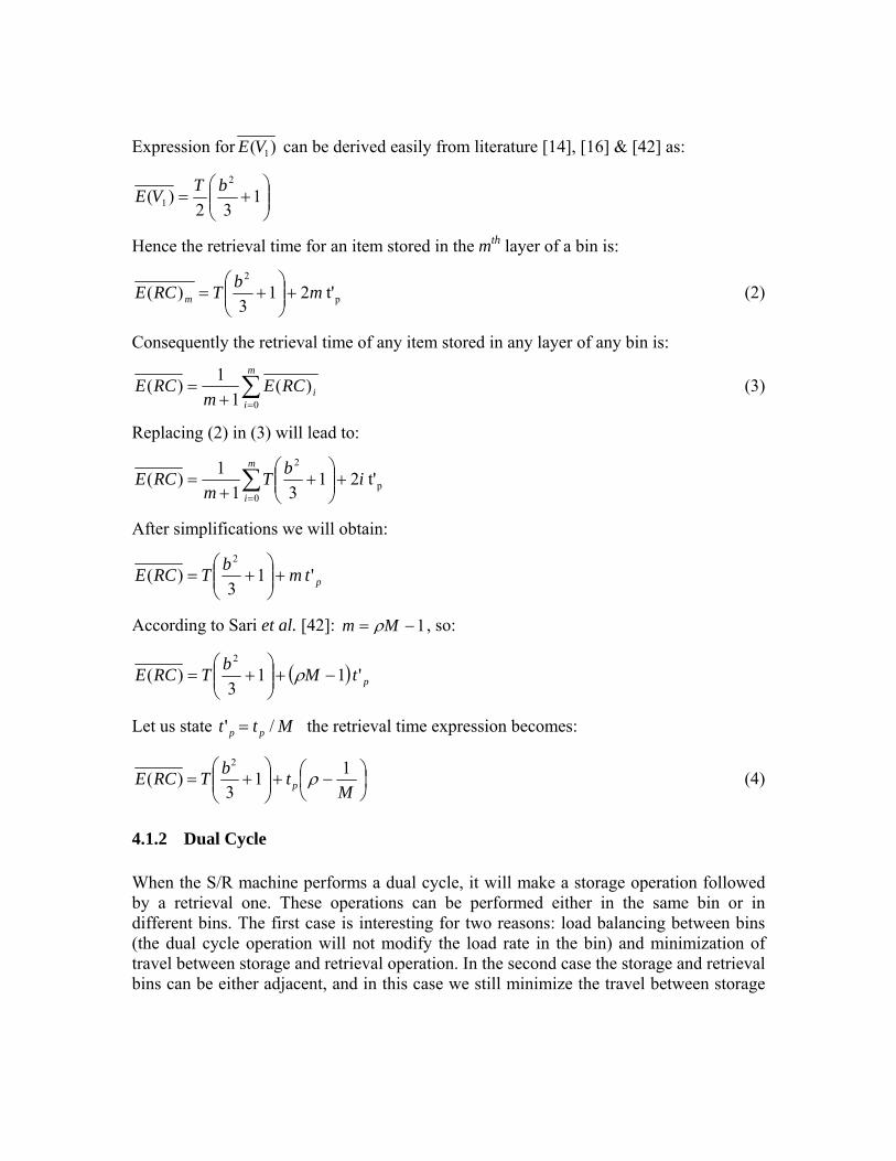
Expression for )( 1VE can be derived easily from literature [14], [16] & [42] as:
⎟⎟⎠
⎞⎜⎜⎝
⎛+= 1
32)(
2
1bTVE
Hence the retrieval time for an item stored in the mth layer of a bin is:
p
2
t'213
)( mbTRCE m +⎟⎟⎠
⎞⎜⎜⎝
⎛+= (2)
Consequently the retrieval time of any item stored in any layer of any bin is:
∑=+
=m
iiRCE
mRCE
0)(
11)( (3)
Replacing (2) in (3) will lead to:
∑=
+⎟⎟⎠
⎞⎜⎜⎝
⎛+
+=
m
iibT
mRCE
0p
2
t'2131
1)(
After simplifications we will obtain:
ptmbTRCE ' 13
)(2
+⎟⎟⎠
⎞⎜⎜⎝
⎛+=
According to Sari et al. [42]: 1−= Mm ρ , so:
( ) ptMbTRCE ' 113
)(2
−+⎟⎟⎠
⎞⎜⎜⎝
⎛+= ρ
Let us state /' Mtt pp = the retrieval time expression becomes:
⎟⎠⎞
⎜⎝⎛ −+⎟⎟
⎠
⎞⎜⎜⎝
⎛+=
MtbTRCE p
113
)(2
ρ (4)
4.1.2 Dual Cycle When the S/R machine performs a dual cycle, it will make a storage operation followed by a retrieval one. These operations can be performed either in the same bin or in different bins. The first case is interesting for two reasons: load balancing between bins (the dual cycle operation will not modify the load rate in the bin) and minimization of travel between storage and retrieval operation. In the second case the storage and retrieval bins can be either adjacent, and in this case we still minimize the travel between storage

and retrieval bins; or far from each other’s which represent the most general case. Consequently, we will consider to scenarios in our study: first storage and retrieval are made in the same or two adjacent bins; second these operations are made in any to bins of the system rack. These two scenarios are schematized in figure 4.
In the case where the storage and retrieval are made in the same or two adjacent bins (figure 4(a)), we add to expression (4), pt ' : the time necessary to go from the bin storing end to the retrieval one (see figure 3(b) and 4(a)):
ptRCEDCE ')()( +=
After simplifications we will obtain:
ptbTDCE 13
)(2
ρ+⎟⎟⎠
⎞⎜⎜⎝
⎛+= (5)
In the case where the storage and retrieval are made in two different bins (figure 4(b)), we add to expression (4) )(TBE , the time necessary to travel from the storing bin to the retrieval one:
)()()( TBERCEDCE += (6)
According to Bozer and White [14]: ⎟⎟⎠
⎞⎜⎜⎝
⎛−+=
30631)(
32 bbTTBE (7)
Replacing (4) and (7) in (6) will lead to:
⎟⎠⎞
⎜⎝⎛ −+⎟⎟
⎠
⎞⎜⎜⎝
⎛−+=
MtbbTDCE p
13023
4)(32
ρ (8)
E(V1)
E(V1)
t’1
t’1 E(V1)
E(V1)
t’1 E(TB)
Figure 4: Dual cycle of S/R machine (dwell point at P/D station). (a) Storage & retrieval in adjacent bins (b) Storage & retrieval in any bins

4.2 Dwell Point at the Center of the Rack Face In this section, let us investigate the single and dual cycle travel time’s models of the single machine flow rack AS/RS when the S/R machine dwell point is at the center of the rack face. 4.2.1 Single Cycle For storage operation, as stated in figure 5(a), the S/R machine will first travel from its dwell point (center of rack face) to the P/D station; this travel is equal to T/2. It will load the product and then travel from P/D station to storage bin where it will unload the product and finally from storage bin to dwell point. These travels are represented by the following expression
2)()()( 21
TVEVESCE ++= (9)
Similarly to )( 1VE , expression for )( 2VE can be derived easily from literature [14] [16] [42] as:
⎟⎟⎠
⎞⎜⎜⎝
⎛+=
21
62)(
2
2bTVE
Replacing )( 1VE , and )( 2VE in (9) by their respective expressions will lead to:
⎟⎟⎠
⎞⎜⎜⎝
⎛+=
45
4)(
2bTSCE
For Retrieval operation, as stated in figure 5(b), the S/R machine will first travel from its dwell point (center of rack face) to the retrieval bin where it will load the products preceding the desired one and travel to the nearest bin storage end to unload them (one round trip for each product). Then it will load the desired product and travel to P/D station where it will unload it and finally return to dwell point. However, this last travel (dashed arrows in figures 5 and 6) might not be taken into account in the retrieval expected travel time, as the retrieval operation is satisfied once the product reaches the P/D station. Also, it should not be taken into account in the computation of the throughput of the S/R machine as this travel is done only if there is no storage or retrieval request; which means that the machine is going to be idle for a while. Nevertheless, if travel times models are used to determine the total workload of the S/R machine as in the case of energy evaluation, or maintenance planning it is necessary to include this last travel. On the other hand, this travel is perfectly constant and well known to be equal to T/2 and can be added a posteriori to the final equation. Consequently, we will not take

T/2
E(V1)
E(V2)
t’1
Figure 5: Single cycle of S/R machine (dwell point at rack face center). (a) Storage (b) Retrieval
E(V2)
T/2
E(V1)
into account this travel time in the following. The expected retrieval time can be written as:
pm mtVEVERCE '2)()()( 21 ++=
Derivations are similar to those presented in section 4.1.1. Finally the expected retrieval time when the dwell point position of the S/R machine is at the center of the rack can be written as:
⎟⎠⎞
⎜⎝⎛ −+⎟⎟
⎠
⎞⎜⎜⎝
⎛+=
MtbTRCE p
143
4)(
2
ρ
4.2.2 Dual Cycle Figure 6 depicts the different displacements of the S/R machine in case of a dual cycle and a dwell point position at the rack face center. When schematics of figure 4 and 6 are compared, it can be noticed that the difference in travel time between the two cases is constant and equals T/2. Consequently, dual cycle travel time will be equal to:
ptbTDCE 23
3)(
2
ρ+⎟⎟⎠
⎞⎜⎜⎝
⎛+=
In the case where the storage and retrieval are made in the same or two adjacent bins and:
⎟⎠⎞
⎜⎝⎛ −+⎟⎟
⎠
⎞⎜⎜⎝
⎛−+=
MtbbTDCE p
13026
11)(32
ρ
In the case where the storage and retrieval are made in any bins,

4.3 Dwell Point strategies comparison In this section we will compare the developed travel time models for the two dwell point position to establish which position will minimize the time response to a storage or a retrieval request (single cycle) or both of them (dual cycle).
Table 1: travel time models comparison Dwell point
position )(SCE )(RCE
)(DCE storage & retrieval
in adjacent bins
)(DCE storage & retrieval in any bins
P/D station ⎟⎟
⎠
⎞⎜⎜⎝
⎛+1
3
2bT ⎟⎠⎞
⎜⎝⎛ −+⎟⎟
⎠
⎞⎜⎜⎝
⎛+
MtbT p
113
2
ρ ptbT 13
2
ρ+⎟⎟⎠
⎞⎜⎜⎝
⎛+ ⎟
⎠⎞
⎜⎝⎛ −+⎟⎟
⎠
⎞⎜⎜⎝
⎛−+
MtbbT p
13023
4 32
ρ
Rack face
center ⎟⎟⎠
⎞⎜⎜⎝
⎛+
45
4
2bT ⎟⎠⎞
⎜⎝⎛ −+⎟⎟
⎠
⎞⎜⎜⎝
⎛+
MtbT p
143
4
2
ρ ptbT 23
3
2
ρ+⎟⎟⎠
⎞⎜⎜⎝
⎛+ ⎟
⎠⎞
⎜⎝⎛ −+⎟⎟
⎠
⎞⎜⎜⎝
⎛−+
MtbbT p
13026
11 32
ρ
Diff 1 ⎟⎟⎠
⎞⎜⎜⎝
⎛−
41
12
2bT ⎟⎟⎠
⎞⎜⎜⎝
⎛+
41
12
2bT 2T
− 2T
−
Diff 2 ⎟⎟⎠
⎞⎜⎜⎝
⎛−
41
12
2bT ⎟⎟⎠
⎞⎜⎜⎝
⎛−−
1241 2bT T− T−
The two first rows of table 1 one summarize the travel time’s models development
presented in sections 4.1 & 4.2. The two last rows present the difference between these models as follows:
Figure 6: Dual cycle of S/R machine (dwell point at rack face center). (a) Storage & retrieval in adjacent bins (b) Storage & retrieval in any bins
E(V1) t’1
E(V1)
t’1
T/2 T/2
E(TB)
T/2
E(V1)
E(V1) T/2 t’1
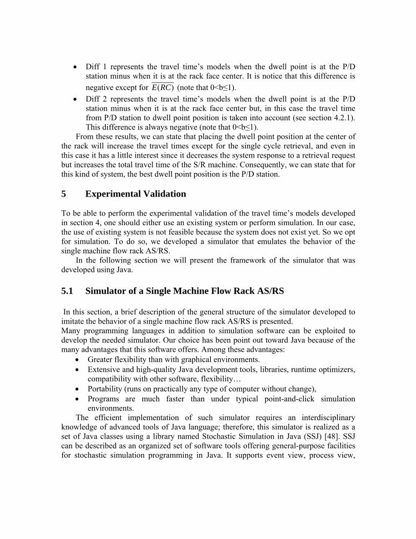
• Diff 1 represents the travel time’s models when the dwell point is at the P/D station minus when it is at the rack face center. It is notice that this difference is negative except for )(RCE (note that 0<b≤1).
• Diff 2 represents the travel time’s models when the dwell point is at the P/D station minus when it is at the rack face center but, in this case the travel time from P/D station to dwell point position is taken into account (see section 4.2.1). This difference is always negative (note that 0<b≤1).
From these results, we can state that placing the dwell point position at the center of the rack will increase the travel times except for the single cycle retrieval, and even in this case it has a little interest since it decreases the system response to a retrieval request but increases the total travel time of the S/R machine. Consequently, we can state that for this kind of system, the best dwell point position is the P/D station. 5 Experimental Validation To be able to perform the experimental validation of the travel time’s models developed in section 4, one should either use an existing system or perform simulation. In our case, the use of existing system is not feasible because the system does not exist yet. So we opt for simulation. To do so, we developed a simulator that emulates the behavior of the single machine flow rack AS/RS.
In the following section we will present the framework of the simulator that was developed using Java. 5.1 Simulator of a Single Machine Flow Rack AS/RS In this section, a brief description of the general structure of the simulator developed to imitate the behavior of a single machine flow rack AS/RS is presented. Many programming languages in addition to simulation software can be exploited to develop the needed simulator. Our choice has been point out toward Java because of the many advantages that this software offers. Among these advantages:
• Greater flexibility than with graphical environments. • Extensive and high-quality Java development tools, libraries, runtime optimizers,
compatibility with other software, flexibility… • Portability (runs on practically any type of computer without change), • Programs are much faster than under typical point-and-click simulation
environments. The efficient implementation of such simulator requires an interdisciplinary
knowledge of advanced tools of Java language; therefore, this simulator is realized as a set of Java classes using a library named Stochastic Simulation in Java (SSJ) [48]. SSJ can be described as an organized set of software tools offering general-purpose facilities for stochastic simulation programming in Java. It supports event view, process view,

Figure 7 : General framework of the single machine flow rack AS/RS simulator.
Event
ArriverProduit
+ Actions() :void
EndOfsimulation
+ Actions() :void
ArriverCommande
+ Actions() :void
DeplaceMachine
+ Actions() :void
SimulateOnRun
+ melangeTab() :ArrayList <<create>>+SimulateOnRun(): SimulateOnRun + raport() :void + simulateOnRun () :void
∼ Tempdestockage :double=0 + raport :String ∼ positionInit :int=-1 ∼ inter_commande: double ∼ inter_produit: double ∼ tempsExe :double ∼ rang :double=0 ∼ Ercsim :double=0 ∼ Tempsimmax :double
ASRS ∼ Stock :ArrayList[] + distance :int[][] − b: double − l,h,d: double − M : int − ro : float − Nl, Nh : int − th,tv,tp :double − T :double <<create>>+ASRS() :ASRS + Stocker() :void + Destocher() :int
continuous simulation, and arbitrary mixtures of these views. SSJ is an organized collection of Java packages whose purpose is to facilitate simulation programming in the general purpose Java language. An early version was described by L’Ecuyer, Meliani, and Vaucher [49].
In order to modelize our system we have created six subclasses: ”ASRS”,
“ArriverCommande”, “ArriverProduit”, “DeplaceMachine”, “EndOfsimulation”, and “simulatOnRun”, which are defined as subclasses of the abstract class Event. Following the event class structure, for each sub-class, an action method is defined and is executed each time the event occurs. Figure 7 depicts the constitution of each of these classes and the relationship between them. These classes can be described as:
The class “ASRS” represents a flow-rack AS/RS and its proprieties (number of vertical and horizontal bins, number of storage segments in a bin, length; height; and depth of a storage segment, number of bins on each row and each column, normalization factor, load rate, shape factor…).
The class “ArriverCommande” represents a request for item to be retrieved, when the “ArriverCommande” event happens, it schedules another event “ArriverCommande” after a time specified at the initialization of the program.
The class “ArriverProduit” represents an arrival of item to P/D Station, when the “ArriverProduit” event occurs, it schedules another event “ArriverProduit” after a time specified at the initialization of the program.
The class “DeplaceMachine” represents the move of the S/R machine, this event is triggered by the "Arrivercommande" event or "ArriverProduit" event, when this event takes place, the S/R machine moves to store or retrieve item in or from the flow-rack AS/RS.
The class “EndOfsimulation”, will trigger the end of simulation. The class “simulatOnRun”: in this class we initialize the simulation and schedule
an event “EndOfsimulation” after a desired time of simulation, it schedules the first “ArriverCommande” event and the first “ArriverProduit” event, and start the simulation.
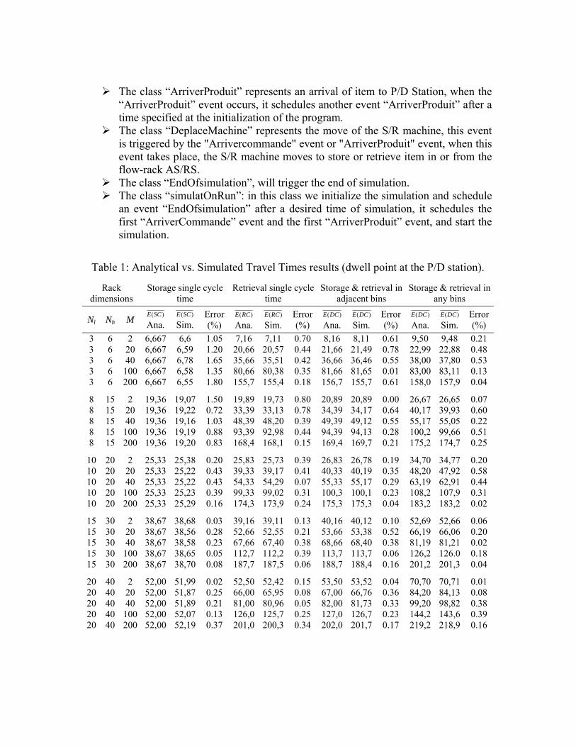
Table 1: Analytical vs. Simulated Travel Times results (dwell point at the P/D station).
Rack dimensions
Storage single cycle time
Retrieval single cycle time
Storage & retrieval in adjacent bins
Storage & retrieval in any bins
Nl Nh M )(SCE
Ana. )(SCE
Sim. Error (%)
)(RCE Ana.
)(RCE Sim.
Error (%)
)(DCE Ana.
)(DCE Sim.
Error (%)
)(DCE Ana.
)(DCE Sim.
Error (%)
3 6 2 6,667 6,6 1.05 7,16 7,11 0.70 8,16 8,11 0.61 9,50 9,48 0.21 3 6 20 6,667 6,59 1.20 20,66 20,57 0.44 21,66 21,49 0.78 22,99 22,88 0.48 3 6 40 6,667 6,78 1.65 35,66 35,51 0.42 36,66 36,46 0.55 38,00 37,80 0.53 3 6 100 6,667 6,58 1.35 80,66 80,38 0.35 81,66 81,65 0.01 83,00 83,11 0.13 3 6 200 6,667 6,55 1.80 155,7 155,4 0.18 156,7 155,7 0.61 158,0 157,9 0.04
8 15 2 19,36 19,07 1.50 19,89 19,73 0.80 20,89 20,89 0.00 26,67 26,65 0.07 8 15 20 19,36 19,22 0.72 33,39 33,13 0.78 34,39 34,17 0.64 40,17 39,93 0.60 8 15 40 19,36 19,16 1.03 48,39 48,20 0.39 49,39 49,12 0.55 55,17 55,05 0.22 8 15 100 19,36 19,19 0.88 93,39 92,98 0.44 94,39 94,13 0.28 100,2 99,66 0.51 8 15 200 19,36 19,20 0.83 168,4 168,1 0.15 169,4 169,7 0.21 175,2 174,7 0.25
10 20 2 25,33 25,38 0.20 25,83 25,73 0.39 26,83 26,78 0.19 34,70 34,77 0.20 10 20 20 25,33 25,22 0.43 39,33 39,17 0.41 40,33 40,19 0.35 48,20 47,92 0.58 10 20 40 25,33 25,22 0.43 54,33 54,29 0.07 55,33 55,17 0.29 63,19 62,91 0.44 10 20 100 25,33 25,23 0.39 99,33 99,02 0.31 100,3 100,1 0.23 108,2 107,9 0.31 10 20 200 25,33 25,29 0.16 174,3 173,9 0.24 175,3 175,3 0.04 183,2 183,2 0.02
15 30 2 38,67 38,68 0.03 39,16 39,11 0.13 40,16 40,12 0.10 52,69 52,66 0.06 15 30 20 38,67 38,56 0.28 52,66 52,55 0.21 53,66 53,38 0.52 66,19 66,06 0.20 15 30 40 38,67 38,58 0.23 67,66 67,40 0.38 68,66 68,40 0.38 81,19 81,21 0.02 15 30 100 38,67 38,65 0.05 112,7 112,2 0.39 113,7 113,7 0.06 126,2 126.0 0.18 15 30 200 38,67 38,70 0.08 187,7 187,5 0.06 188,7 188,4 0.16 201,2 201,3 0.04
20 40 2 52,00 51,99 0.02 52,50 52,42 0.15 53,50 53,52 0.04 70,70 70,71 0.01 20 40 20 52,00 51,87 0.25 66,00 65,95 0.08 67,00 66,76 0.36 84,20 84,13 0.08 20 40 40 52,00 51,89 0.21 81,00 80,96 0.05 82,00 81,73 0.33 99,20 98,82 0.38 20 40 100 52,00 52,07 0.13 126,0 125,7 0.25 127,0 126,7 0.23 144,2 143,6 0.39 20 40 200 52,00 52,19 0.37 201,0 200,3 0.34 202,0 201,7 0.17 219,2 218,9 0.16

5.2 Simulation Results and Discussion Simulation has been performed using the simulator presented in section 5.1, on a PC. Rack dimensions have been varied from very small system (36 storage segments) to very large systems (160000 storage segments). The other characteristics of the considered AS/RS have been taken as follows: the travel times t’h=t’v=t’p=1 and load rate ρ =0.75.
Table 2: Analytical vs. Simulated Travel Times results (dwell point at rack face center).
Rack dimensions
Storage single cycle time
Retrieval single cycle time
Storage & retrieval in adjacent bins
Storage & retrieval in any bins
Nl Nh M )(SCE
Ana. )(SCE
Sim. Error (%)
)(RCE Ana.
)(RCE Sim.
Error (%)
)(DCE Ana.
)(DCE Sim.
Error (%)
)(DCE Ana.
)(DCE Sim.
Error (%)
3 6 2 7.5 7.36 1.87 5.5 5.51 0.18 10.66 10.62 0.38 12 11.97 0.25 3 6 20 7.5 7.42 1.07 19.00 18.95 0.26 24.16 24.03 0.54 25.5 25.38 0.47 3 6 40 7.5 7.37 1.73 33.99 33.86 0.38 39.16 39.1 0.15 40.49 40.3 0.47 3 6 100 7.5 7.32 2.4 79 79.19 0.24 84.16 84.07 0.11 85.5 85.61 0.13 3 6 200 7.5 7.34 2.13 154 154 0.02 159.2 159 0.13 160.5 160.4 0.04
8 15 2 22.04 21.54 2.27 15.04 14.57 3.13 28.39 27.83 1.97 34.17 33.36 2.37 8 15 20 22.04 21.72 1.45 28.54 28.32 0.77 41.89 41.78 0.26 47.67 47.42 0.52 8 15 40 22.04 21.7 1.54 43.54 43.33 0.48 56.89 56.69 0.35 62.67 62.45 0.35 8 15 100 22.04 21.73 1.41 88.54 88.03 0.58 101.9 101.8 0.12 107.7 107.2 0.47 8 15 200 22.04 21.78 1.18 163.5 163.1 0.26 176.9 176.8 0.06 182.7 182.2 0.24
10 20 2 28.5 28.35 0.53 19.5 19.45 0.26 36.33 36.32 0.03 44.19 44.17 0.05 10 20 20 28.5 28.23 0.95 32.99 32.7 0.88 49.83 49.63 0.4 57.7 57.51 0.33 10 20 40 28.5 28.28 0.77 48 47.69 0.65 64.83 64.84 0.02 72.69 72.55 0.19 10 20 100 28.5 28.27 0.81 92.99 92.66 0.35 109.8 109.8 0.07 117.7 117.5 0.15 10 20 200 28.5 28.3 0.7 168 168.1 0.03 184.8 184.6 0.13 192.7 192.3 0.19
15 30 2 43.49 43.32 0.39 29.5 29.4 0.34 54.66 54.62 0.07 67.19 67.21 0.03 15 30 20 43.49 43.26 0.53 42.99 42.82 0.4 68.16 68.07 0.13 80.69 80.67 0.02 15 30 40 43.49 43.3 0.44 58 57.92 0.14 83.16 83.04 0.14 95.69 95.44 0.26 15 30 100 43.49 43.32 0.39 103 102.7 0.27 128.2 128.1 0.09 140.7 140.6 0.06 15 30 200 43.49 43.36 0.3 178 177.4 0.37 203.2 204 0.41 215.7 215.5 0.1
20 40 2 58.5 58.33 0.29 39.5 39.41 0.23 73 72.98 0.03 90.19 90.31 0.13 20 40 20 58.5 58.31 0.32 53 52.86 0.26 86.5 86.24 0.3 103.7 103.4 0.27 20 40 40 58.5 58.28 0.38 67.99 67.7 0.43 101.5 101.4 0.11 118.7 118.4 0.29 20 40 100 58.5 58.38 0.21 113 112.8 0.2 146.5 146.7 0.11 163.7 163.5 0.13 20 40 200 58.5 58.36 0.24 188 187.7 0.19 221.5 223.1 0.74 238.7 238.7 0.01
The aim of this section is to evaluate and compare the analytical expected retrieval
times of a single machine flow rack AS/RS, to the one obtained by simulation. For this, we conducted 200 simulations (each one replicated ten times) by varying the AS/RS rack dimensions. Tables 2 and 3 summarize the simulation results. These results have been obtained using random storage and retrieval methods. Column 1, 2 and 3 of these tables represent respectively the number of bins on each row (Nl) and each column (Nh) and number of storage segments in a bin (M). While the other columns present storage and

retrieval single cycles times, and dual cycle times for storage and retrieval in adjacent bins as well as in any two bins. For each of these cycle times, analytical and simulated models and the error between them are provided. According to the results presented in tables 2 and 3 one can notice the following:
• The errors between analytical and simulated results are in most of cases less than one percent.
• For each model the error between analytical and the simulation decrease when the dimension of system increase. This is foreseeable since the analytical model use a continuous approximation of the real system.
• In some cases, the error can increase to more than 3%. But this error still be reasonable. All the simulations have been performed for square in time systems, further investigations should be done to verify the developed model performances in non square in time systems
6 Conclusion
In this paper, we developed analytical travel times models for a single machine flow rack AS/RS. These models stand for storage and retrieval single and dual cycle travel times. For dual cycle, two strategies were investigated: store and retrieve in adjacent bins or in any two bins of the rack. Two dwell point positions were considered. These concerns led us to eight models that have been compared to find the best dwell point position. These models have been developed on the basis of a continuous rack face approximation.
An experimental validation through computer simulation has been conducted to verify the ability of the developed models to predict the real behavior of the system. For that, a simulator based on Java programming language was developed to emulate the functioning of a real single machine flow rack AS/RS. The computer simulation showed that the error, of the continuous approximate models relative to simulated models, is acceptable for most cases when the system is square in time. However, more investigations should be carried out for non square in time systems.
The closed form expected travel time model, presented in this work, can be used to : establish performance standards and evaluate throughput performance for single machine flow rack AS/RS design configurations as well as comparison with other types of AS/RS for choice decision. Also, they can be used as a basis of comparison for evaluating performance improvements of different storage techniques. References [1] Lee, H.F., “Performance analysis for automated storage and retrieval systems,” IIE
Transactions, 29, 15-28 (1997). [2] Allen, S.L., “A selection guide to AS/R systems,” Industrial Engineering, 24, 28-
31(1992).

[3] Hausman, W.H., Schwarz, L.B., and Graves, S.C., “Optimal storage assignment in automatic warehousing systems,” Management Science, 22, 629-638 (1976).
[4] Sand, G. M., “Stacker crane product handling systems,” Eastman Kodak Company
(1976). [5] Barrett, B.G., “An empirical comparison of high-rise warehouse policies for
operator-controlled stacker cranes,” Logistics Research and Analysis, Eastman Kodak Company (1977).
[6] Graves, S.C., Hausman, W.H., and Schwarz, L.B., “Storage retrieval interleaving in
automatic warehousing systems,” Management Science, 23, 935-945 (1977). [7] Sarker, B.R., Babu, P.S., “Travel time models in automated storage/retrieval
systems: a critical review,” International Journal of Production Economics, 40, 173-184 (1995).
[8] Rouwenhorst, B., Reuter, B., Stockrahm, V., van Houtum, G.J., Mantel, R.J., Zijm,
W.H.M., “Warhouse design and control: Framework and literature review,” European Journal of Operational Research, 122, 3, 515-533 (2000).
[9] Gu, J.X., Goetschalckx, M., and McGinnis, L.F., “Research on warehouse
operation: A comprehensive review,” European Journal of Operational Research, 177, 1, 1-21 (2007).
[10] De koster, R., Le-Duc, T., and Roodbergen, K.J., “Design and control of warehouse
order picking: A literature review,” European Journal of Operational Research, 182, 2, 481-501 (2007).
[11] Roodbergen, K.J., and Vis, I.F.A., “A survey of literature on automated storage and
retrieval systems,” European Journal of Operational Research, 194, 343–362 (2009).
[12] Gu, J.X., Goetschalckx, M., and McGinnis, L.F., “Research on warehouse design
and performance evaluation: A comprehensive review,” European Journal of Operational Research, 203, 3, 539-549 (2010).
[13] Gagliardi, J.P., renaud, J., and Ruiz, A., “Models for automated storage and
retrieval systems:A literature review, ” International Journal of Production Research, (2011). DOI:10.1080/00207543.2011.633234.
[14] Bozer, Y.A., and White, J.A., “Travel-time models for automated storage/retrieval
systems,” IIE Transactions, 16, 329-338 (1984). [15] Egbelu, P.J., “Framework for dynamic positioning of storage/retrieval machines in
an automated storage/retrieval system,” International Journal of Production Research, 29, 17-37 (1991).

[16] Peters, B.A., Smith, J.S., and Hale, T.S., “Closed form models for determining the
optimal dwell point location in automated storage and retrieval systems,” International Journal of Production Research, 34, 1757-1771 (1996).
[17] Park, B.C., “An optimal dwell point for automated storage/retrieval systems with
uniformly distributed, rectangular racks,” International Journal of Production Research, 39, 1469-1480 (2001).
[18] Van Den Berg, J.P., “Analytic expressions for the optimal dwell point in an
automated storage/retrieval system,” International Journal of Production Economics, 76, 1, 13-25 (2002).
[19] Meller, R.D., and Mungwattana, A., “AS/RS dwell-point strategy selection at high
system utilization: a simulation study to investigate the magnitude of the benefit,” International Journal of Production Research, 43, 24, 5217-5227 (2005).
[20] Hale, T.S., Huq, F., and Pujari, N.A., “Closed form models for dwell point
locations in automated storage carousel systems,” International Journal of Production Research, 46, 4, 1089-1098 (2008).
[21] Hwang, H., and Lee, S.B., “Travel-time models considering the operating
characteristics of the storage and retrieval machine,” International Journal of Production Research, 28, 1779-1789 (1990).
[22] Chang, D.T., Wen, U.P., and Lin, J.T., “The impact of acceleration/deceleration on
travel-time models for automated storage retrieval systems,” IIE Transactions, 27, 108-111 (1995).
[23] Dallari, F., Marchet, G., Ruggeri, R., “Optimisation of man-on-board automated
storage/retrieval systems,” Integrated Manufacturing Systems, 11, 87-93 (2000). [24] Van Den Berg, J.P., and Gademann, A.J.R.M., “Simulation study of an automated
storage/retrieval system,” International Journal of Production Research, 38, 1339-1356 (2000).
[25] Ashayeri, J., and Heuts, R.M., “A geometrical approach to computing expected
cycle times for zone-based storage layouts in AS/RS,” International Journal of Production Research, 40, 4467-4483 (2002).
[26] Park, B.C., “Performance of automated storage/retrieval systems with non-square-
in-time racks and two-class storage,” International Journal of Production Research, 44, 1107–1123 (2006).
[27] Park, B.C., Foley, R.D. and Frazelle, E.H., “Performance of miniload systems with
two-class storage,” European Journal of Operational Research, 170, 144–155 (2006).

[28] De koster, M.B.M., Le-Anh, T., and Yu, Y., “Optimal storage rack design for a 3-
dimensional compact AS/RS,” International journal of production research, 46, 6, 1495–1514 (2008).
[29] Yu, y., and De koster, M. B. M., “Designing an optimal turnover-based storage rack
for a 3D compact automated storage and retrieval system,” International Journal of Production Research, 47, 6, 1551-1571 (2009).
[30] Fukunari, M., Malmborg, C.J., “A heuristic travel time model for random storage
systems using closest open location load dispatching,” International Journal of Production Research, 46, 8, 2215-2228 (2008).
[31] Ghomri, L., Sari Z., Guezzen, A.H., and Sari, T., “Continuous Models for Single
and Dual Cycle Times of a Multi Aisle Automated Storage and Retrieval System,” INCOM’09, Moscow, Russia (2009).
[32] Kouloughli, S., Sari, Z., and Sari, T., “Optimisation des dimensions d’un AS/RS
multi allées pour un temps de double cycle minimal,” CPI’09, Fez, Morrocco, (2009).
[33] Kouloughli, S., Sari, Z., and Sari, T., “Optimisation des dimensions d'un AS/RS
multi-allée basée sur un modèle analytique du temps de simple cycle, ” Journal Européen des Systèmes Automatisés (JESA), 44, 2, 135-159 (2010).
[34] Parikh, P.J., and Meller, R.D., “A travel-time model for person-onboard order
picking system,” European Journal of Operational Research, 200, 2, 385-394 (2010).
[35] Chen, L., Langevin, A., Riopel, D., “The storage location assignment and
interleaving problem in an automated storage/retrieval system with shared storage,” International Journal of Production Research, 48, 4, 991-1011 (2010).
[36] Ma, X.L., Zhao, L.D., and Schulze, L., “Performance of automated storage/retrieval
systems under stochastic demand using queueing theory,” International Journal of Innovative Computing Information and Control, 5, 12A, 4469-4477 (2009).
[37] Tanaka, S., and Araki, M., “Routing problem under the shared storage policy for
unit-load automated storage and retrieval systems with separate input and output point,” International Journal of Production Research, 47, 9, 2391-2408 (2009).
[38] Ekren, B.Y., and Heragu, S.S., “Simulation-based regression analysis for the rack
configuration of an autonomous vehicule storage and retrieval system,” International Journal of Production Research, 48, 21, 6257-6274 (2010).

[39] Ekren, B.Y., and Heragu, S.S., Krishnamurthy, A., and Malmborg, C.J., “Simulation based experimental design to identify factors affecting performance of AVS/RS,” Computers and Industrial Engineering, 58, 1, 175-185 (2010).
[40] He, S.J., and Luo, J., “Deablock control of autonomous vehicule storage and
systems timed Petri nets and digraph tools,” International Journal of Production Research, 47, 12, 3253-3263 (2009).
[41] Lerher, T., Sraml, M., Potrc, I., and Tollazzi, T., “Travel time models for double-
deep automated storage and retrieval systems,” International Journal of Production Research, 48, 11, 3151-3172 (2010).
[42] Sari, Z., Saygin, C., and Ghouali, N., “Travel Time Models for Flow-Rack
Automated Storage and Retrieval Systems,” International Journal of Advanced Manufacturing Technology, 25, 9-10, 979-987, (2005).
[43] Sari, Z., Grassman, S., and Ghouali, N., “ Impact of Pickup/Dropoff Stations and
Restoring Conveyor Locations on Retrieval Time Models of Flow-rack Automated Storage and Retrieval Systems ,” Production Planning and Control, 18, 2, 105-116 (2007).
[44] Sari, Z., “Performance evaluation of flow-rack and unit load Automated storage &
retrieval systems” Proceedings of ISTEC 2010, 605-615 (2010). Famagusta, Cyprus,
[45] Bessenouci, H.N., Sari, Z., and Ghomri, L., “Metaheuristic based control of a flow
rack automated storage retrieval system,” Journal of Intelligent Manufacturing, (2010). DOI 10.1007/s10845-010-0432-1.
[46] Meghelli-Gaouar, N., and Sari, Z., “ Assessment of Performance of a Class-Based
Storage in a Flow-Rack AS/RS ,” Journal of Studies on Manufacturing, 1, 2-3, 100-107 (2010).
[47] Cardin, O., Castagna, P., Sari, Z., and Meghelli, N., “Performance evaluation of In-
Deep Class Storage for Flow-Rack AS/RS,” International Journal of Production Research, (2012). DOI:10.1080/00207543.2011.624561
[48] L’Ecuyer, P. and Buist, E., “simulation in Java with SSJ,” Proceedings of the
Winter Simulation Conference, 611-620 (2005). [49] L’Ecuyer, P., Meliani, L. and Vaucher. J., “A framework for stochastic simulation
in Java,” Proceedings of the Winter Simulation Conference, 234-242 (2002).