Embed Size (px)
Citation preview
635
From: Handbook of Environmental Engineering, Volume 3: Physicochemical Treatment ProcessesEdited by: L. K. Wang, Y.-T. Hung, and N. K. Shammas © The Humana Press Inc., Totowa, NJ
16Physicochemical Treatment Processes
for Water Reuse
Saravanamuthu Vigneswaran, Huu Hao Ngo, Durgananda Singh Chaudhary, and Yung Tse Hung
CONTENTS
INTRODUCTION
CONVENTIONAL PHYSICOCHEMICAL TREATMENT PROCESSES
MEMBRANE PROCESSES
REFERENCES
1. INTRODUCTION
The continuing processes of industrialization and urbanization coupled with uncon-trolled population growth, deforestation, and water pollution are exerting pressure onthe planet’s limited freshwater resources. The need to recycle and reuse wastewater hasbeen more and more realized, as the global supplies of clean water diminish anddemand for water rises. Advanced wastewater treatment is becoming an internationalfocus for the rational use of scarce water resources, and as means of safeguardingaquatic environments from the harm caused by wastewater disposal. Conventionally,wastewater was discharged into the environment after removing the majority of sus-pended solids in primary treatment and biodegradable organic substance in secondarytreatment. These treatments are not sufficient to produce effluent of reusable quality.Now the trend is changing toward the total water recycle approach, which promotesecological sustainability by managing the treated wastewater as a resource instead of awaste and, at the same time, reducing the demand for water from the existing waterresources. Tertiary wastewater treatment is therefore required to remove most of theremaining organics, solids, and pathogenic microorganisms.
The advanced treatment processes utilized in the polishing wastewater-treatment sys-tem are physicochemical in nature. Coagulation–flocculation, filtration, and sedimentationfollowed by chlorination are the standard form of advanced treatment scheme that ismostly utilized in practice. In coagulation–flocculation processes, chemicals such asalum, ferric chloride, and some advanced forms of flocculant are added to neutralize thecharge on particles and to agglomerate the colloidal particles into settleable and filterableparticles. In these processes, most of the organic pollutants are destabilized and are
subsequently removed in sedimentation and/or filtration processes. In the treatmentplant, a mechanical mixer can be provided to disperse coagulant chemicals uniformly(by rapid mixing) and bring the destabilized colloidal particles together to form flocs(by slow mixing). Sedimentation is the solid–liquid separation process that makes useof the gravitational settling principle. The sedimentation tank is provided to collect thesettleable particles destabilized and agglomerated in coagulation–flocculation pro-cesses and to pass relatively clear effluent to the filtration process. Filtration is the processwhereby the impurities are removed by a combination of different processes such assedimentation, interception, adsorption, and straining. Straining removes those suspendedparticles that are too large to pass through the pores of the filter bed. Sedimentationremoves fine suspended solids as they are deposited onto the surface of the filter mediagrains. Adsorption occurs as a result of electrostatic attraction of particles toward thefilter media particles of the filter bed. The organics substances accumulated on the fil-ter medium due to all these actions may undergo biochemical and bacterial activity andthus organics are biodegradated.
When the filtrate contains an excessive amount of dissolved organic substances,then it is further treated by adsorption and ion-exchange processes. The effluent isfinally disinfected with chlorine or UV and discharged into waterways for variousreuse purposes.
With technological advances and the ever-increasing stringency of water-quality cri-teria, membrane processes are becoming a more attractive solution to the challenge ofwater reuse. The use of membrane technology, particularly in wastewater treatment andreuse, has received increased attention since early 1990s. Membrane technologiescurrently being used in different industries include microfiltration (MF), ultrafiltration(UF), nanofiltration (NF), reverse osmosis (RO), pervaporation, dialysis, and electro-dialysis. Although membrane processes such as reverse osmosis and nanofiltrationcould in theory remove all pollutants, including dissolved organics, their operationalcosts are high because of high-energy requirements and membrane fouling. Micro- andultrafiltration are cost-effective options, but they cannot remove dissolved organic matterdue to their relatively larger pore sizes. Therefore, in water-reuse applications, ultrafil-tration or microfiltration needs to be combined with biological processes. For example,in a water-mining project in Canberra, Australia, biological filtration is combined withcontinuous microfiltration. Microfiltration is preferable choice in wastewater treatmentand reuse applications because it can be operated at very low pressure (1 bar) comparedto ultrafiltration (100–500 kPa) and reverse osmosis (2000–8000 kPa).
2. CONVENTIONAL PHYSICOCHEMICAL TREATMENT PROCESSES
2.1. Principle2.1.1. Coagulation–Flocculation
The principal use of coagulation and flocculation is to agglomerate particles intosettleable or filterable flocs prior to sedimentation or filtration. Coagulation consists ofadding chemicals to the colloidal suspensions. This results in particle destabilization by areduction in the repulsive forces, which tend to keep particles apart. The colloidal parti-cles then agglomerate to form settleable or filterable solids by the process of flocculation.
636 Saravanamuthu Vigneswaran et al.
Coagulation involves the reduction of surface charges and the formation of complexhydrous oxides. The process forms either flocculant suspensions of compounds, whichentrap desired pollutants and carry them out of solution, or insoluble precipitates of thepollutants themselves. The coagulation phase is practically instantaneous and the particlesare usually submicroscopic in size. The chemistry involved is very complex and theknown major interactions that occur are (a) the reduction of the zeta potential to adegree where the attractive van der Waals’ forces and the agitation provided cause theparticles to coalesce; (b) the aggregation of particles by interparticulate bridgingbetween reactive groups of colloids; and (c) the enmeshment of particles in the precip-itate floc that is formed. The interparticulate forces acting on a colloidal particle arerepulsive forces, due to the electrostatic zeta potential, and attractive forces, due to vander Waals’ forces acting between the particles. The net resultant force is attractive to acertain distance. Beyond this distance, the net resultant is repulsive. When a coagulantsalt is added to a water, it dissociates, and the metallic ion undergoes hydrolysis and cre-ates positive hydroxometallic ion complexes. There are a number of species of hydrox-ometallic complexes formed because the complexes, which are hydrolysis products,tend to polymerize. These complexes are polyvalent with high positive charges, and areadsorbed onto the surface of the negative colloids. This results in a reduction of the zetapotential to a level where the colloids are destabilized. The coagulation of colloids byorganic polymers occurs by a chemical interaction or bridging. The polymers haveignitable groups such as carboxyl, amino, and sulfonic, and these groups bind with reac-tive sites or groups on the surfaces of the colloids. In this manner, several colloids arebound to a simple polymer molecule to form a bridging structure. Bridging betweenparticles is optimum when the colloids are about one-half covered with adsorbedsegments of the polymers.
Collisions of destabilized particles lead to agglomeration. The collisions can occurby three separate mechanisms:
(a) Aggregation resulting from random Brownian movement of fluid molecules (perikineticflocculation). When submicron particles move in water under Brownian motion, they col-lide with other particles. On contact, they form large particles and continue to do so untilthey become too large to be affected by Brownian motion. Perikinetic flocculation is pre-dominant for submicron particles. The higher the initial concentration of particles in thesuspension, the faster is the floc formation, because the opportunity for collision is higher.
(b) Aggregation induced by velocity gradient in the fluid (orthokinetic flocculation).Orthokinetic flocculation that involves particle movement with gentle motion of water con-siders that particles will agglomerate if they collide and become close enough to be withina zone of influence of one another. It also considers that particles have negligible settlingvelocity; hence, there is a need for agitation of the water, or a velocity gradient to promotethe collisions. The rate of flocculation is proportional to the velocity (shear) gradient, thevolume of the zone of influence, and the concentration of particles.
(c) Differential settling, where flocculation is due to the different rates of settling of particlesof different sizes. Larger particles settle faster than smaller particles, which makes therelative velocities between the particles different. This also helps in orthokinetic flocculationas because velocity gradients are produced, causing further agglomeration.
The two main modes of process operations used in flocculation (i.e., creation ofvelocity gradients) are hydraulic flocculator and mechanical flocculator. Mechanical
Physicochemical Treatment Processes for Water Reuse 637
638 Saravanamuthu Vigneswaran et al.
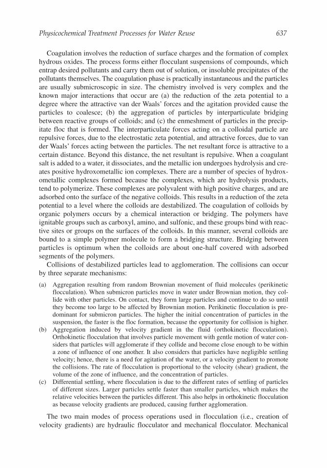
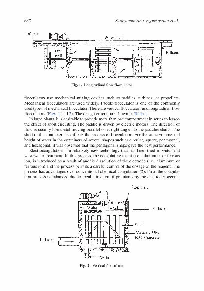
flocculators use mechanical mixing devices such as paddles, turbines, or propellers.Mechanical flocculators are used widely. Paddle flocculator is one of the commonlyused types of mechanical flocculator. There are vertical flocculators and longitudinal-flowflocculators (Figs. 1 and 2). The design criteria are shown in Table 1.
In large plants, it is desirable to provide more than one compartment in series to lessonthe effect of short circuiting. The paddle is driven by electric motors. The direction offlow is usually horizontal moving parallel or at right angles to the paddles shafts. Theshaft of the container also affects the process of flocculation. For the same volume andheight of water in the containers of several shapes such as circular, square, pentagonal,and hexagonal, it was observed that the pentagonal shape gave the best performance.
Electrocoagulation is a relatively new technology that has been tried in water andwastewater treatment. In this process, the coagulating agent (i.e., aluminum or ferrousion) is introduced as a result of anodic dissolution of the electrode (i.e., aluminum orferrous ion) and the process permits a careful control of the dosage of the reagent. Theprocess has advantages over conventional chemical coagulation (2). First, the coagula-tion process is enhanced due to local attraction of pollutants by the electrode; second,
Fig. 1. Longitudinal flow flocculator.
Fig. 2. Vertical flocculator.
Physicochemical Treatment Processes for Water Reuse 639
the cathode generates hydrogen bubbles promoting the growth of precipitate flocs foreasier separation; and third, the strength of the flocs formed during electrocoagulationis higher than that formed during chemical coagulation.
2.1.2. Sedimentation
Sedimentation is a solid–liquid process, which is based on the gravitational settlingprinciple. In wastewater-treatment plants, sedimentation is used to remove settleablesolids. The efficiency of the sedimentation process is related to various factors such asloading rate, water quality, particle/floc size and weight, tank geometry, and so on. Asedimentation tank can be designed for optimum efficiency (90–95% floc removal) orcan be designed to operate at lower efficiencies, allowing the filters to remove most ofthe remaining solids. Usually the latter approach leads to a total plant optimization.Particles settle from suspension in different ways, depending on the characteristics andconcentration of the particles. Four distinct types of sedimentation have been classified,reflecting the influence of the concentration of the suspension and flocculating propertiesof the particles:
(a) First-class clarification: Settling of dilute suspensions that have little or no tendency to floc-culate.
(b) Second-class clarification: Settling of dilute suspensions with flocculation taking place duringthe settling process.
(c) Zone settling: Particles settle as a mass and not as discrete particles. Interparticle forceshold the particles (which are sufficiently close) in a fixed position, so that the settlementtakes place in a zone.
(d) Compression settling: settlement takes place over the resistance provided by the compactingmass resulting from particles that are in contact with each other.
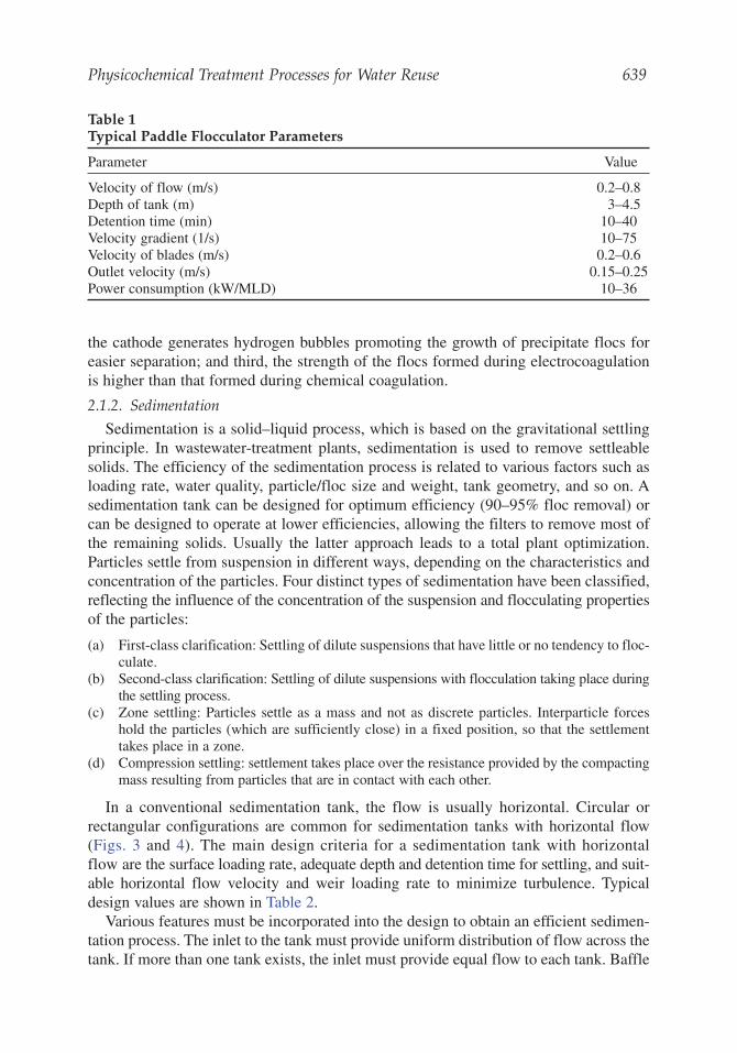
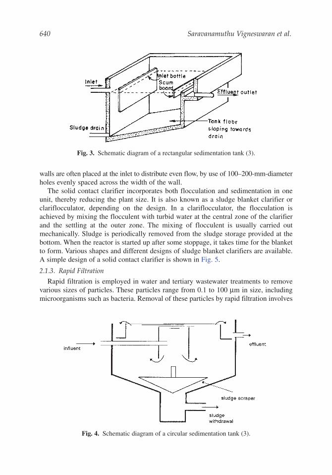
In a conventional sedimentation tank, the flow is usually horizontal. Circular orrectangular configurations are common for sedimentation tanks with horizontal flow(Figs. 3 and 4). The main design criteria for a sedimentation tank with horizontalflow are the surface loading rate, adequate depth and detention time for settling, and suit-able horizontal flow velocity and weir loading rate to minimize turbulence. Typicaldesign values are shown in Table 2.
Various features must be incorporated into the design to obtain an efficient sedimen-tation process. The inlet to the tank must provide uniform distribution of flow across thetank. If more than one tank exists, the inlet must provide equal flow to each tank. Baffle
Table 1Typical Paddle Flocculator Parameters
Parameter Value
Velocity of flow (m/s) 0.2–0.8Depth of tank (m) 3–4.5Detention time (min) 10–40Velocity gradient (1/s) 10–75Velocity of blades (m/s) 0.2–0.6Outlet velocity (m/s) 0.15–0.25Power consumption (kW/MLD) 10–36
640 Saravanamuthu Vigneswaran et al.
walls are often placed at the inlet to distribute even flow, by use of 100–200-mm-diameterholes evenly spaced across the width of the wall.
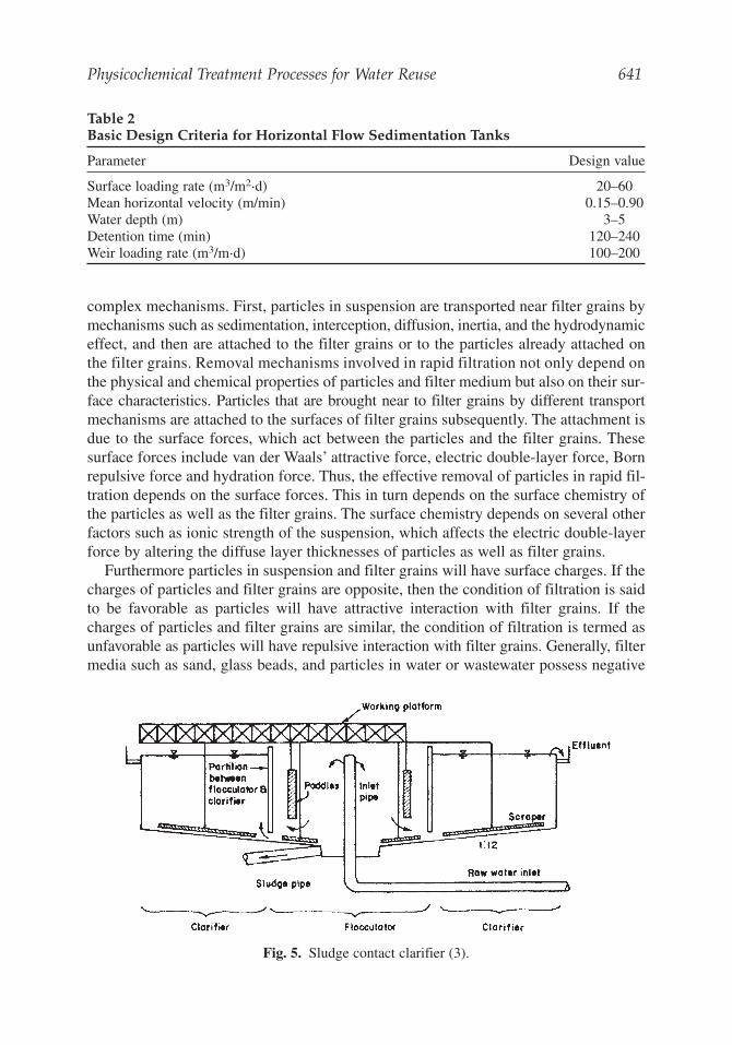
The solid contact clarifier incorporates both flocculation and sedimentation in oneunit, thereby reducing the plant size. It is also known as a sludge blanket clarifier orclariflocculator, depending on the design. In a clariflocculator, the flocculation isachieved by mixing the flocculent with turbid water at the central zone of the clarifierand the settling at the outer zone. The mixing of flocculent is usually carried outmechanically. Sludge is periodically removed from the sludge storage provided at thebottom. When the reactor is started up after some stoppage, it takes time for the blanketto form. Various shapes and different designs of sludge blanket clarifiers are available.A simple design of a solid contact clarifier is shown in Fig. 5.
2.1.3. Rapid Filtration
Rapid filtration is employed in water and tertiary wastewater treatments to removevarious sizes of particles. These particles range from 0.1 to 100 μm in size, includingmicroorganisms such as bacteria. Removal of these particles by rapid filtration involves
Fig. 3. Schematic diagram of a rectangular sedimentation tank (3).
Fig. 4. Schematic diagram of a circular sedimentation tank (3).
Physicochemical Treatment Processes for Water Reuse 641
complex mechanisms. First, particles in suspension are transported near filter grains bymechanisms such as sedimentation, interception, diffusion, inertia, and the hydrodynamiceffect, and then are attached to the filter grains or to the particles already attached onthe filter grains. Removal mechanisms involved in rapid filtration not only depend onthe physical and chemical properties of particles and filter medium but also on their sur-face characteristics. Particles that are brought near to filter grains by different transportmechanisms are attached to the surfaces of filter grains subsequently. The attachment isdue to the surface forces, which act between the particles and the filter grains. Thesesurface forces include van der Waals’ attractive force, electric double-layer force, Bornrepulsive force and hydration force. Thus, the effective removal of particles in rapid fil-tration depends on the surface forces. This in turn depends on the surface chemistry ofthe particles as well as the filter grains. The surface chemistry depends on several otherfactors such as ionic strength of the suspension, which affects the electric double-layerforce by altering the diffuse layer thicknesses of particles as well as filter grains.
Furthermore particles in suspension and filter grains will have surface charges. If thecharges of particles and filter grains are opposite, then the condition of filtration is saidto be favorable as particles will have attractive interaction with filter grains. If thecharges of particles and filter grains are similar, the condition of filtration is termed asunfavorable as particles will have repulsive interaction with filter grains. Generally, filtermedia such as sand, glass beads, and particles in water or wastewater possess negative
Table 2Basic Design Criteria for Horizontal Flow Sedimentation Tanks
Parameter Design value
Surface loading rate (m3/m2.d) 20–60Mean horizontal velocity (m/min) 0.15–0.90Water depth (m) 3–5Detention time (min) 120–240Weir loading rate (m3/m.d) 100–200
Fig. 5. Sludge contact clarifier (3).
642 Saravanamuthu Vigneswaran et al.
surface charge; thus, most of the time filtration will occur under unfavorable conditions,if no chemicals are added to alter the conditions
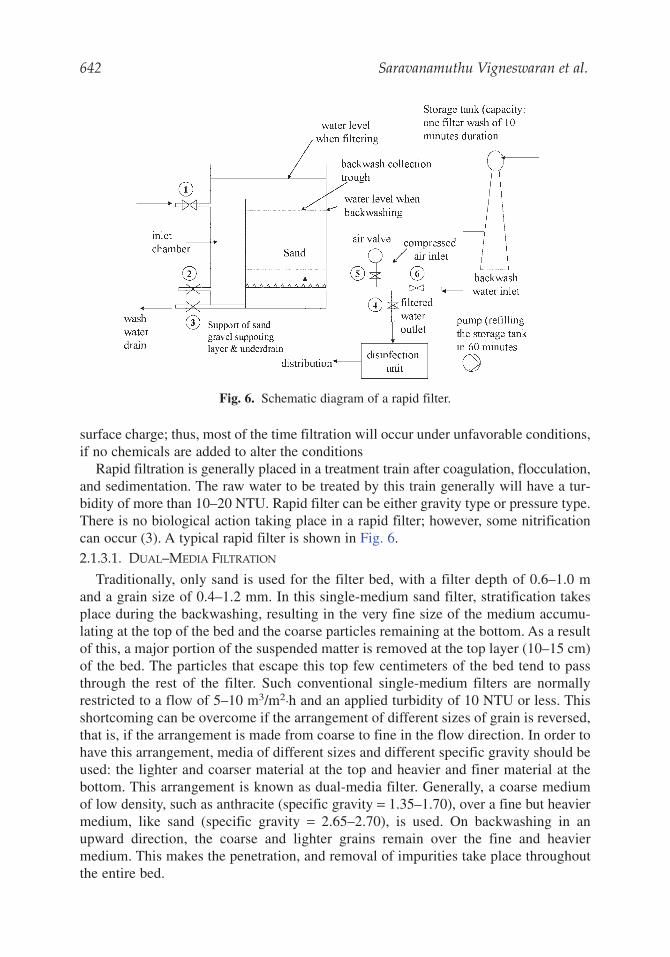
Rapid filtration is generally placed in a treatment train after coagulation, flocculation,and sedimentation. The raw water to be treated by this train generally will have a tur-bidity of more than 10–20 NTU. Rapid filter can be either gravity type or pressure type.There is no biological action taking place in a rapid filter; however, some nitrificationcan occur (3). A typical rapid filter is shown in Fig. 6.2.1.3.1. DUAL–MEDIA FILTRATION
Traditionally, only sand is used for the filter bed, with a filter depth of 0.6–1.0 mand a grain size of 0.4–1.2 mm. In this single-medium sand filter, stratification takesplace during the backwashing, resulting in the very fine size of the medium accumu-lating at the top of the bed and the coarse particles remaining at the bottom. As a resultof this, a major portion of the suspended matter is removed at the top layer (10–15 cm)of the bed. The particles that escape this top few centimeters of the bed tend to passthrough the rest of the filter. Such conventional single-medium filters are normallyrestricted to a flow of 5–10 m3/m2.h and an applied turbidity of 10 NTU or less. Thisshortcoming can be overcome if the arrangement of different sizes of grain is reversed,that is, if the arrangement is made from coarse to fine in the flow direction. In order tohave this arrangement, media of different sizes and different specific gravity should beused: the lighter and coarser material at the top and heavier and finer material at thebottom. This arrangement is known as dual-media filter. Generally, a coarse mediumof low density, such as anthracite (specific gravity = 1.35–1.70), over a fine but heaviermedium, like sand (specific gravity = 2.65–2.70), is used. On backwashing in anupward direction, the coarse and lighter grains remain over the fine and heaviermedium. This makes the penetration, and removal of impurities take place throughoutthe entire bed.
Fig. 6. Schematic diagram of a rapid filter.
Physicochemical Treatment Processes for Water Reuse 643
2.1.3.2. FLOATING–MEDIUM FILTER
Filtration technology has been used for centuries in water treatment. Its use is becom-ing increasingly important as water reuse is envisaged. There have been a number ofmodifications made during the last two decades. The two main objectives to upgradethis technology are (a) to make the system compact and energy efficient to reduce thecapital and operating costs and (b) to meet stringent water-quality standards for waterreuse. There have been many designs, namely, high-rate multimedia filter, mobile-bedfilter. The major problem of these designs is the high energy requirement for cleaningof the filter. The floating-medium filter developed overcomes these short comings.Generally, a large quantity of water for backwash is required to fluidize the highlydense filter media such as sand on anthracite. Backwash requirements become veryhigh in the case of direct filtration (more specifically in contact flocculation/filtration). Indirect filtration, the entire solid–liquid separation is within the filter bed itself. With theobjective of reducing the backwash requirement, the use of synthetic buoyant filtermaterials (less dense than water) such as polypropylene, polystyrene, etc., are used. Asaturated/unsaturated downflow buoyant-medium packed-bed filtration system within-line flocculation arrangement has been successfully developed for water and tertiarywastewater treatment (4,5).
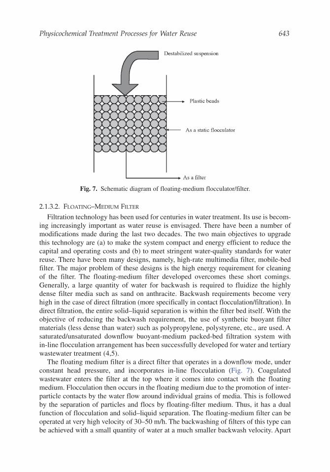
The floating medium filter is a direct filter that operates in a downflow mode, underconstant head pressure, and incorporates in-line flocculation (Fig. 7). Coagulatedwastewater enters the filter at the top where it comes into contact with the floatingmedium. Flocculation then occurs in the floating medium due to the promotion of inter-particle contacts by the water flow around individual grains of media. This is followedby the separation of particles and flocs by floating-filter medium. Thus, it has a dualfunction of flocculation and solid–liquid separation. The floating-medium filter can beoperated at very high velocity of 30–50 m/h. The backwashing of filters of this type canbe achieved with a small quantity of water at a much smaller backwash velocity. Apart
Fig. 7. Schematic diagram of floating-medium flocculator/filter.
644 Saravanamuthu Vigneswaran et al.
from this advantage, floating-filter media are also found to have a high solids retentioncapacity and low head loss development.
Ngo and Vigneswaran (6) found that the most suitable backwash method for a floating-medium filter was a combination air (30 kPa) and water (20–30 m3/m2.h) in the upwarddirection for 30 s followed with upward flow of water (20–30 m3/m2.h) for another 30 s.The backwash frequency of 90–120 min was found to be suitable for a long filter run.The consumption of backwash water was only 1.2–1.8% of filtered water production. Inthis backwash method, no air is necessary and the water requirement can be reduced byanother 35%. An option of mechanical backwash using rotating paddles, followed bydownflow water backwash could be the cheapest backwash method.
2.1.4. Adsorption
Adsorption is a surface phenomenon by which molecules of pollutants (adsorbates)are attracted to the surface of adsorbent by intermolecular forces of attraction. It takesplace when atoms of surface functional groups of adsorbent (activated carbon) donateelectrons to the adsorbate molecules (usually organic pollutants). The position of thefunctional groups (which are generated during activation process) of the adsorbentdetermines the type of adsorbent–adsorbate bond, and thus the type of adsorption. Thephysical adsorption is mainly caused by van der Waals’ and electrostatic bonds betweenthe adsorbate molecules and the atoms of the functional groups. The process is reversible,and thus desorption of the adsorbed solute can occur. The physical adsorption takesplace at lower temperature (in the neighborhood of room temperature), and it is not site-specific. The adsorption can occur over the entire surface of the adsorbent at multilayers.On the other hand, the chemical adsorption involves ionic or covalent bond formationbetween the adsorbate molecules and the atoms of the functional groups of the adsor-bent. The chemical adsorption is irreversible, and the heat of adsorption is typicallyhigh. The chemical adsorption process is site-specific and it occurs only at certain sitesof the adsorbent at only one layer (monolayer).
Because the wastewater contains a large amount of organic and inorganic substances,it is possible that both physical and chemical adsorption takes place when it comes intocontact with an adsorbent (usually activated carbon). However, for simplicity, only thephysical adsorption process is discussed, as most of the adsorption-separation processesdepend on physical adsorption.
The adsorption process with wastewater is competitive in nature. The extent ofcompetition depends on the strength of adsorption of the competing molecules, theconcentrations of these molecules, and the characteristics of the adsorbent (activatedcarbon). In a competitive adsorption environment, desorption of a compound maytakes place by displacement by other compounds, as the adsorption process isreversible in nature. It sometimes results in an effluent concentration of an adsorbategreater than the influent concentration (7).
There are basically four steps an adsorbate passes through to get adsorbed onto theporous adsorbent. First, the adsorbate must be transported from bulk solution to theboundary layer of the wastewater surrounding the adsorbent (bulk solution trans-port). The transport occurs by diffusion if the adsorbent is in a quiescent state. Inthe fixed-bed or in the turbulent mixing batch reactors, the bulk solution transport
Physicochemical Treatment Processes for Water Reuse 645
occurs by turbulent mixing. Second, the adsorbate must be transported by moleculardiffusion through the boundary layer surrounding the adsorbent particles (film dif-fusion transport). Third, after passing through the boundary layer, the adsorbate mustbe transported through the pores of the adsorbent to the available adsorption sites(pore transport). The intraparticle transport may occur by molecular diffusionthrough the wastewater solution in the pores (pore diffusion) of by diffusion alongthe surface of the adsorbent (surface diffusion). Finally, when the adsorbate reaches theadsorption site, the adsorption bond is formed between the adsorbate and the adsor-bent. This step is very rapid for physical adsorption (8). Thus, it is either the bulksolution transport or film diffusion transport or pore transport that controls the rateof organic removal from the wastewater. In turbulent mixing condition (in fixed-bedor in batch reactor), it is most likely that a combination of film diffusion and porediffusion controls the rate of adsorption of organics. At the initial stage, the film dif-fusion may control the adsorption rate but after the accumulation of adsorbateswithin the pore of the adsorbent, it is possible that the adsorption rate is controlledby the pore transport.2.1.4.1. DESIGN OF ADSORPTION SYSTEMS
The adsorption processes used in practice are either batch mode or fixed bed modedepending on the characteristics of the adsorbent. In the batch mode, adsorbent is addedto the tank containing wastewater. The pollutants such as persisting organics, pesticides,herbicides, and heavy metals are adsorbed onto the adsorbent surface and are subse-quently removed by sedimentation–filtration processes. In fixed–bed mode, adsorbentsare packed in a column, and the wastewater is passed through the column either fromthe top or from the bottom (fluidized mode). The pollutants are adsorbed on the adsorbentsurface and thus the effluent of better quality is achieved.
Activated carbons, both granular activated carbon (GAC) and powdered activatedcarbon (PAC), are the oldest and most widely used adsorbents commercially as well asin the laboratory. They can be used in wastewater effluent treatment, potable watertreatment, solvent recovery, air treatment, decolorizing, and many more other appli-cations. The GAC is used as a fixed filter bed whereas the PAC is used directly in theaeration tank.
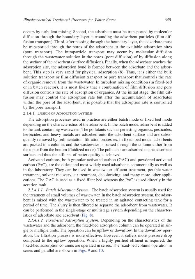
2.1.4.1.1. Batch Adsorption System. The batch adsorption system is usually used forthe treatment of small volumes of wastewater. In the batch adsorption system, the adsor-bent is mixed with the wastewater to be treated in an agitated contacting tank for aperiod of time. The slurry is then filtered to separate the adsorbent from wastewater. Itcan be performed in the single-stage or multistage system depending on the character-istics of adsorbate and adsorbent (Fig. 8).
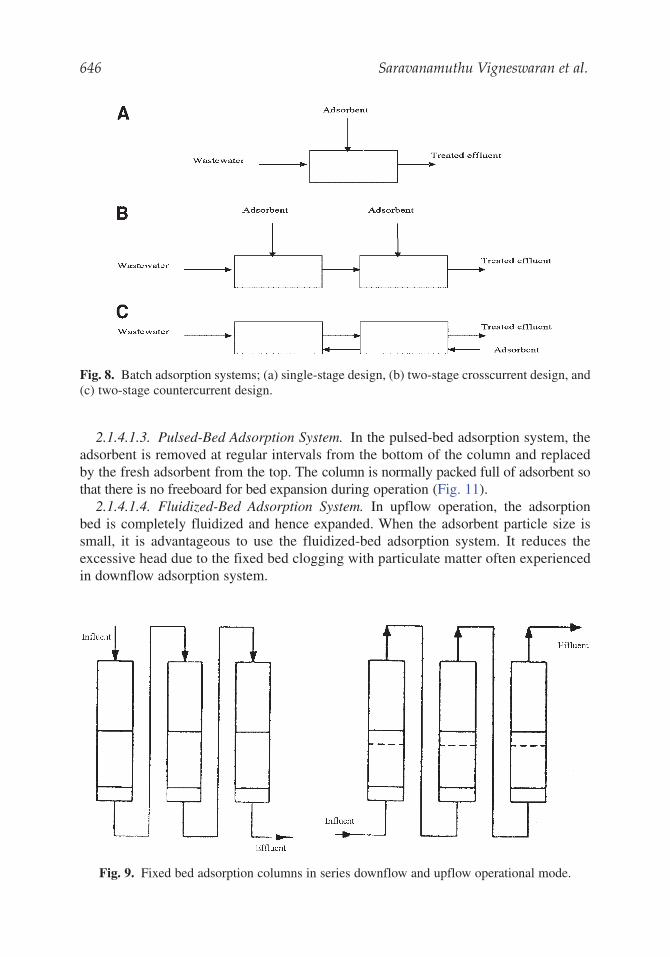
2.1.4.1.2. Fixed-Bed Adsorption System. Depending on the characteristics of thewastewater and the adsorbent, the fixed-bed adsorption column can be operated in sin-gle or multiple units. The operation can be upflow or downflow. In the downflow oper-ation, the filtration process is more effective. However, it suffers more pressure dropcompared to the upflow operation. When a highly purified effluent is required, thefixed-bed adsorption columns are operated in series. The fixed-bed column operation inseries and parallel are shown in Figs. 9 and 10.
646 Saravanamuthu Vigneswaran et al.
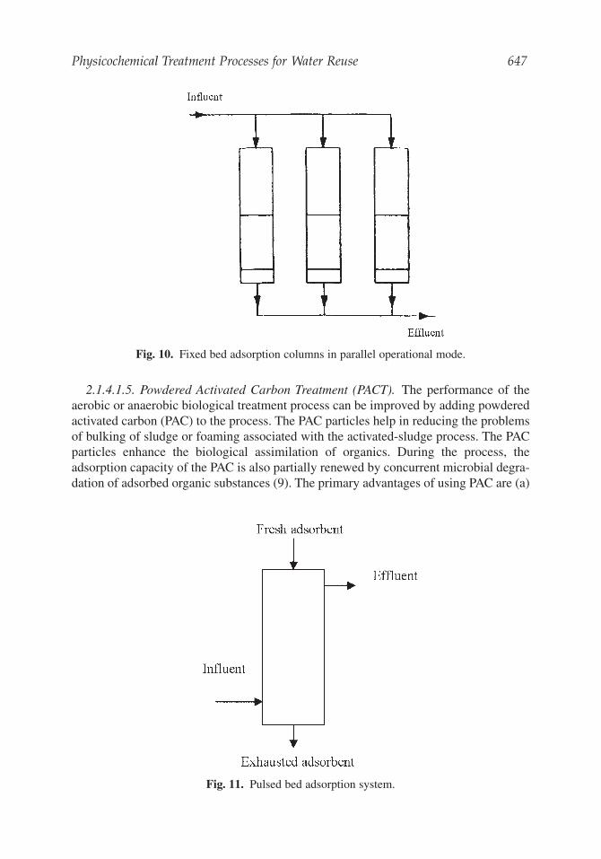
2.1.4.1.3. Pulsed-Bed Adsorption System. In the pulsed-bed adsorption system, theadsorbent is removed at regular intervals from the bottom of the column and replacedby the fresh adsorbent from the top. The column is normally packed full of adsorbent sothat there is no freeboard for bed expansion during operation (Fig. 11).
2.1.4.1.4. Fluidized-Bed Adsorption System. In upflow operation, the adsorptionbed is completely fluidized and hence expanded. When the adsorbent particle size issmall, it is advantageous to use the fluidized-bed adsorption system. It reduces theexcessive head due to the fixed bed clogging with particulate matter often experiencedin downflow adsorption system.
Fig. 8. Batch adsorption systems; (a) single-stage design, (b) two-stage crosscurrent design, and(c) two-stage countercurrent design.
Fig. 9. Fixed bed adsorption columns in series downflow and upflow operational mode.
Physicochemical Treatment Processes for Water Reuse 647
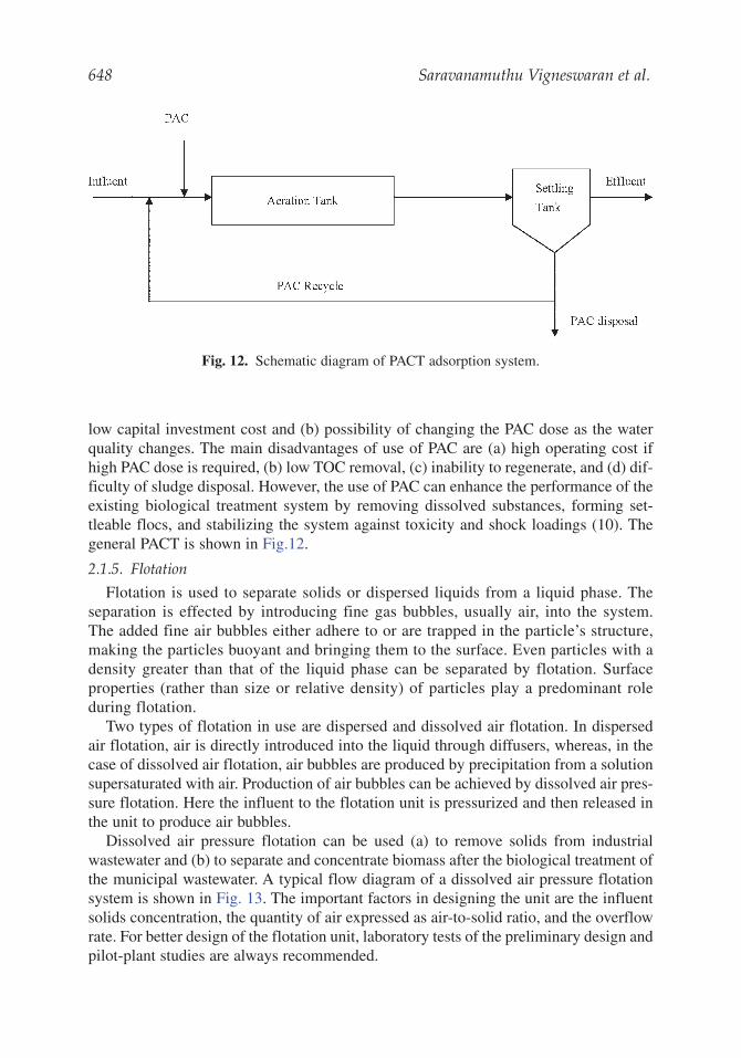
2.1.4.1.5. Powdered Activated Carbon Treatment (PACT). The performance of theaerobic or anaerobic biological treatment process can be improved by adding powderedactivated carbon (PAC) to the process. The PAC particles help in reducing the problemsof bulking of sludge or foaming associated with the activated-sludge process. The PACparticles enhance the biological assimilation of organics. During the process, theadsorption capacity of the PAC is also partially renewed by concurrent microbial degra-dation of adsorbed organic substances (9). The primary advantages of using PAC are (a)
Fig. 10. Fixed bed adsorption columns in parallel operational mode.
Fig. 11. Pulsed bed adsorption system.
648 Saravanamuthu Vigneswaran et al.
low capital investment cost and (b) possibility of changing the PAC dose as the waterquality changes. The main disadvantages of use of PAC are (a) high operating cost ifhigh PAC dose is required, (b) low TOC removal, (c) inability to regenerate, and (d) dif-ficulty of sludge disposal. However, the use of PAC can enhance the performance of theexisting biological treatment system by removing dissolved substances, forming set-tleable flocs, and stabilizing the system against toxicity and shock loadings (10). Thegeneral PACT is shown in Fig.12.
2.1.5. Flotation
Flotation is used to separate solids or dispersed liquids from a liquid phase. Theseparation is effected by introducing fine gas bubbles, usually air, into the system.The added fine air bubbles either adhere to or are trapped in the particle’s structure,making the particles buoyant and bringing them to the surface. Even particles with adensity greater than that of the liquid phase can be separated by flotation. Surfaceproperties (rather than size or relative density) of particles play a predominant roleduring flotation.
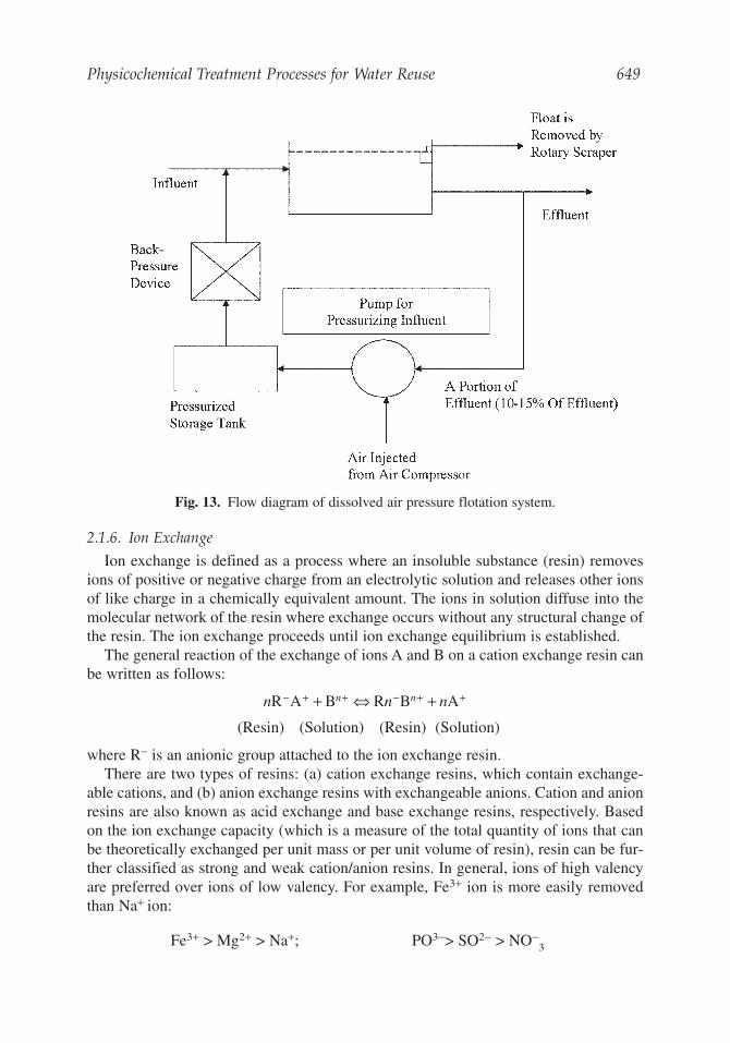
Two types of flotation in use are dispersed and dissolved air flotation. In dispersedair flotation, air is directly introduced into the liquid through diffusers, whereas, in thecase of dissolved air flotation, air bubbles are produced by precipitation from a solutionsupersaturated with air. Production of air bubbles can be achieved by dissolved air pres-sure flotation. Here the influent to the flotation unit is pressurized and then released inthe unit to produce air bubbles.
Dissolved air pressure flotation can be used (a) to remove solids from industrialwastewater and (b) to separate and concentrate biomass after the biological treatment ofthe municipal wastewater. A typical flow diagram of a dissolved air pressure flotationsystem is shown in Fig. 13. The important factors in designing the unit are the influentsolids concentration, the quantity of air expressed as air-to-solid ratio, and the overflowrate. For better design of the flotation unit, laboratory tests of the preliminary design andpilot-plant studies are always recommended.
Fig. 12. Schematic diagram of PACT adsorption system.
Physicochemical Treatment Processes for Water Reuse 649
2.1.6. Ion Exchange
Ion exchange is defined as a process where an insoluble substance (resin) removesions of positive or negative charge from an electrolytic solution and releases other ionsof like charge in a chemically equivalent amount. The ions in solution diffuse into themolecular network of the resin where exchange occurs without any structural change ofthe resin. The ion exchange proceeds until ion exchange equilibrium is established.
The general reaction of the exchange of ions A and B on a cation exchange resin canbe written as follows:
(Resin) (Solution) (Resin) (Solution)
where R− is an anionic group attached to the ion exchange resin.There are two types of resins: (a) cation exchange resins, which contain exchange-
able cations, and (b) anion exchange resins with exchangeable anions. Cation and anionresins are also known as acid exchange and base exchange resins, respectively. Basedon the ion exchange capacity (which is a measure of the total quantity of ions that canbe theoretically exchanged per unit mass or per unit volume of resin), resin can be fur-ther classified as strong and weak cation/anion resins. In general, ions of high valencyare preferred over ions of low valency. For example, Fe3+ ion is more easily removedthan Na+ ion:
Fe3+ > Mg2+ > Na+; PO3−> SO2− > NO−3
n n nn nR A B R B A− + + − + ++ ⇔ +
Fig. 13. Flow diagram of dissolved air pressure flotation system.
650 Saravanamuthu Vigneswaran et al.
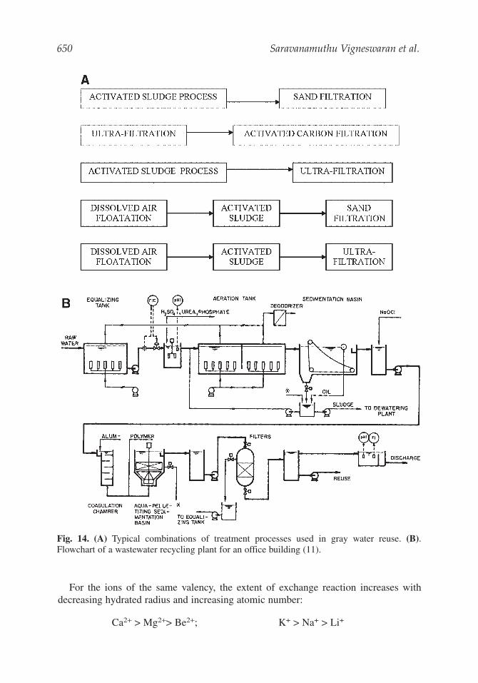
Fig. 14. (A) Typical combinations of treatment processes used in gray water reuse. (B).Flowchart of a wastewater recycling plant for an office building (11).
For the ions of the same valency, the extent of exchange reaction increases withdecreasing hydrated radius and increasing atomic number:
Ca2+ > Mg2+> Be2+; K+ > Na+ > Li+
Physicochemical Treatment Processes for Water Reuse 651
2.2. Application of the Physicochemical Processes in Wastewater Treatmentand Reuse
The physicochemical processes have extensively been used in treating domestic andindustrial wastewater, in combination with other biological treatment processes. In thissection, the application of the physicochemical processes in wastewater treatment andreuse are discussed with some design data.
Different combinations of treatment processes that can be used in grey water recycleare presented in Fig. 14A. The schematic flow diagram of the treatment process used inthe recycle of wastewater in office buildings is shown in Fig. 14B. The general designcriteria of different units that can be used in treatment and reuse of wastewater fromoffice building is shown in Table 3.
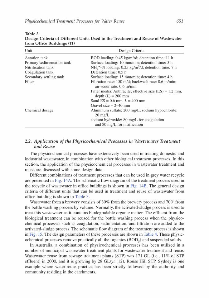
Wastewater from a brewery consists of 30% from the brewery process and 70% fromthe bottle washing process by volume. Normally, the activated-sludge process is used totreat this wastewater as it contains biodegradable organic matter. The effluent from thebiological treatment can be reused for the bottle washing process when the physico-chemical processes such as coagulation, sedimentation, and filtration are added to theactivated-sludge process. The schematic flow diagram of the treatment process is shownin Fig. 15. The design parameters of these processes are shown in Table 4. These physic-ochemical processes remove practically all the organics (BOD5) and suspended solids.
In Australia, a combination of physicochemical processes has been utilized in anumber of municipal wastewater-treatment plants for wastewater treatment and reuse.Wastewater reuse from sewage treatment plants (STP) was 171 GL (i.e., 11% of STPeffluent) in 2000, and it is growing by 28 GL/yr (12). Rouse Hill STP, Sydney is oneexample where water-reuse practice has been strictly followed by the authority andcommunity residing in the catchments.
Table 3Design Criteria of Different Units Used in the Treatment and Reuse of Wastewaterfrom Office Buildings (11)
Unit Design Criteria
Aeration tank BOD loading: 0.45 kg/m3/d; detention time: 11 hPrimary sedimentation tank Surface loading: 10 mm/min; detention time: 5 hNitrification tank NH4
+–N loading: 0.25 kg/m3/d; detention time: 7 hCoagulation tank Detention time: 0.5 hSecondary settling tank Surface loading: 15 mm/min; detention time: 4 hFilter Filtration rate: 150 m/d; backwash rate: 0.6 m/min;
air-scour rate: 0.6 m/minFilter media: Anthracite; effective size (ES) = 1.2 mm,
depth (L) = 200 mmSand ES = 0.6 mm, L = 400 mmGravel size = 2–40 mm
Chemical dosage Aluminum sulfate: 200 mg/L; sodium hypochlorite:20 mg/L
sodium hydroxide: 80 mg/L for coagulationand 80 mg/L for nitrification
652 Saravanamuthu Vigneswaran et al.
The Rouse Hill STP in Sydney, Australia, for example, uses multistage biologicalnutrient removal technology with chemical polishing for phosphorus removal. Thecapacity of the plant is nominally 25,000 equivalent population (EP) (6.75 MLD), butthe capacity of individual processes varies from 25,000 to 100,000 EP. The STP hasbeen designed to achieve the effluent standards shown in Table 5.
The sewage delivered to the plant first undergoes fine screening through fine contin-uous belt screens. Screenings are automatically transported, dewatered and discharged
Fig. 15. Flowchart of a brewery wastewater treatment plant (11).
Table 4Design Criteria of Different Units Used in the Treatment of Beer FactoryWastewater (11)
Unit Design Criteria
Neutralizing basin Detention time: 8 minAeration tank BOD loading: 1.2 kg/m3/d; detention time: 22 hSedimentation basin Surface loading: 10 m/d; detention time: 9 hCoagulated Sedimentation basin Surface loading: 50 m/d; detention time: 2.5 hActivated carbon filter Linear velocity: 5–20 m/hFilter Filtration rate: 200 m/d; backwash rate: 1.0 m/min;
air-scour rate: 1.0 m/min; filter run: 12 h;Filter media
Anthracite: effective size (ES) = 1.2 mm;depth (L) = 200 mm
Sand: ES = 0.6 mm; L = 500 mm
Physicochemical Treatment Processes for Water Reuse 653
into 240 L garbage bins for land fill disposal. Screened sewage flows to a vortex-typegrit trap. The grit from this trap is pumped to cyclone separators and then grit classi-fiers. Grit from this system is loaded into garbage bins for disposal. Sewage is thenchanneled via a flow-measuring flume to the solids separation tank where solids areconcentrated via settling processes. Settled solids are recirculated in the tank, pumpedaway for disposal, or transferred to the biological reactor prefermenter. Flow less thanthree times average dry weather flow (DWF) goes from the solids separation tank to thebiological reactor and the flow greater than three times average DWF is by-passed tochlorine contact tank.
Settled sewage is directed to a multistage biological reactor for organic and nutrientremoval. The reactor includes a prefermenter, denitrification tank having anaerobic,anoxic, and aeration zones. Mixed liquor is recycled from the aeration zone back to theanoxic zones. Aeration is achieved using mechanical aerators. The mixed liquor fromthe biological reactor is settled in circular outward flow steel clarifiers. These areequipped with scum-withdrawal facilities. The return activated sludge is withdrawnfrom each clarifier individually by variable speed pumps at specified rates.
Secondary effluent gravitates to a rapid mix tank for chemical addition and a floccu-lation chamber for floc formation. Flow is then directed to a tertiary clarifier where thesludge is drawn off and recirculated or wasted to the digester. After final clarification,the effluent is filtered through shallow bed sand filters. Effluent is then chlorinated and thechlorinated effluent is then either directed to the wetlands for further polishing or to therecycle system. The treated effluent that meets the turbidity and pH requirements ispumped to another set of chlorine contact tanks. Here chlorine is dosed to give a resid-ual of 0.5 mg/L after 1-h detention as required by the recycled-water specifications(Table 6).
The chlorinated recycle water is then checked for pH and adjusted if required.Recycled water that fully meets the specification is stored in holding tanks and isavailable for delivery to the distribution system. If it does not fully meet specifica-tion, it can be re-worked by directing it back for re-chlorination. Off-specificationwater is drained to a pumping station and passed through the treatment processes. Toreduce the chlorine residual from that required for initial disinfection, each recycled-water reservoir is provided with a dechlorination facility using sodium bi-sulfite. Toguarantee the integrity of the supply, the recycled-water reservoirs are cross con-nected to the potable water reservoirs. Connection to recycled water is mandatory for
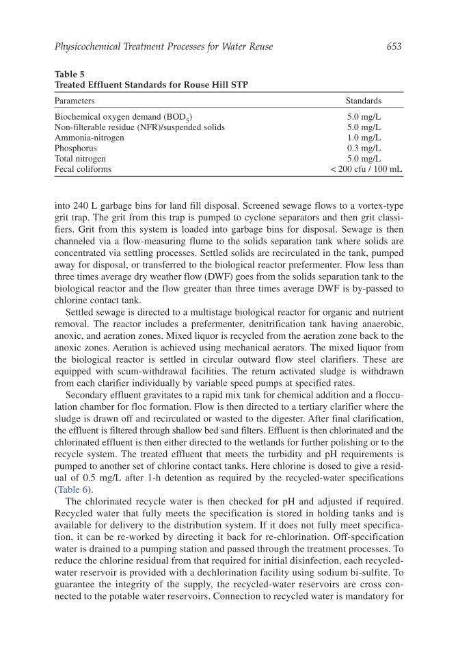
Table 5Treated Effluent Standards for Rouse Hill STP
Parameters Standards
Biochemical oxygen demand (BOD5) 5.0 mg/LNon-filterable residue (NFR)/suspended solids 5.0 mg/LAmmonia-nitrogen 1.0 mg/LPhosphorus 0.3 mg/LTotal nitrogen 5.0 mg/LFecal coliforms < 200 cfu / 100 mL
654 Saravanamuthu Vigneswaran et al.
toilet flushing and outside (yard) uses throughout the new development areas in thecatchments.
The recycled water, however, is not permitted for: (a) drinking, cooking, or kitchenpurposes; (b) bath, showers, hand basins, or personal washing; (c) clothes washing; (d)swimming pools; (e) water-contact recreation; and (f) irrigation of crops for human con-sumption that are neither processed nor cooked.
2.2.1. Semi-Pilot-Scale Application of High-Rate Floating-Medium Filter
2.2.1.1. FLOATING MEDIUM IN DOMESTIC WASTEWATER TREATMENT
The performance of the filter system was studied at a filtration velocity of30 m3/m2.hr using ferric chloride (FeCl3) and polysilicato-iron (PSI) as flocculants. Theeffluent from the diversion chamber of a sewage treatment plant in Sydney, Australiaafter screening was sent to the filter system. The specific characteristics of wastewaterused are summarized in Table 7. The optimum dose of FeCl3 and PSI was found to be15 mg/L and 2.5 mg/L, respectively. The filter was operated with frequent (once in 2 h)but very short backwash (30 s) during the filter runs.
The system was extremely effective in removing phosphorus and a majority of bac-teria from the secondary sewage effluent. During the 16 h of filter run, the number offecal streptococci (FS) and fecal coliform (FC) in the treated effluent were much lowerthan the effluent discharge standard of 200 No./100 mL. The chlorine dose requiredcan thus be significantly reduced. The phosphorus (as orthophosphate) was alsoremoved up to 90%. Head loss development was very low when FeCl3 was used asflocculant (e.g., < 20 cm after 16 h of filtration time). In both cases, the average turbidityand COD of treated effluent were less than 1 NTU and 20 mg/L, respectively. Thephosphorus removal efficiency was 93% at the filtration rate of 15 m3/m2.h and 80%at 45 m3/m2.hr. The head loss development was lower than 24 cm for all cases. Theresults also indicated that the variation in filtration rates had no significant effect on
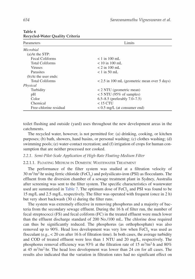
Table 6Recycled-Water Quality Criteria
Parameters Limits
Microbial(a)At the STP:
Fecal Coliforms < 1 in 100 mLTotal Coliforms < 10 in 100 mLViruses < 2 in 100 mLParasites < 1 in 50 mL
(b)At the user ends:Total Coliforms < 2.5 in 100 mL (geometric mean over 5 days)
PhysicalTurbidity < 2 NTU (geometric mean)pH < 5 NTU (95% of samples)Color 6.5–8.5 (preferably 7.0–7.5)Chemical < 15 CTUFree-chlorine residual < 0.5 mg/L (at consumer end)
Physicochemical Treatment Processes for Water Reuse 655
the fecal coliform and fecal streptococci removal (up to 30 m3/m2.h) (Table 8). The fil-ter system was just as effective in removing bacteria when operated at a filtrationvelocity of 15 m3/m2.h, as it was when operated at 30 m3/m2.h. However, a lot morenumbers of FC and FS escaped through the filter bed when the filtration rate wasincreased to 45 m3/m2.h. The total backwash water for the filter run was less than 1%of water production when using air and water backwash or combined mechanical andwater backwash.
2.2.1.2. FLOATING MEDIUM IN SHRIMP FARM WASTEWATER TREATMENT AND RECYCLE
Pilot-scale studies were also conducted with the effluent from a shrimp farm inQueensland, Australia. In this study, the floating-medium filter was used as a floccula-tor/prefilter in the filter system together with sand filter as a subsequent polishing filter.The system was operated at 15 m3/m2.h with in-line polyaluminum chloride (WAC-HB)addition arrangement. The depth of floating medium (3.8 mm polypropylene beads) andsand (effective size, ES = 1.7 mm) was 60 cm each. The characteristics of prawn farmeffluent used are summarized in Table 9.
The effluent quality from this combined filter system was acceptable for dischargingin terms of turbidity (2.4 NTU), SS (5 mg/L), and PO4-P (0.04 mg/L). The head lossdevelopment was less than 20 cm after a 180 min filter run. A trial was also conductedwith the same conditions but without addition of WAC-HB. The removal efficiency wasabout 50%. A comparative study conducted on backwash showed that 1 min wash perevery 90 min could maintain high effluent quality for a long filter run. It is noted thatthe consumption of backwash water was about 1% of filtered water production. Thequantity of backwash water was even smaller when a mechanical backwash method was
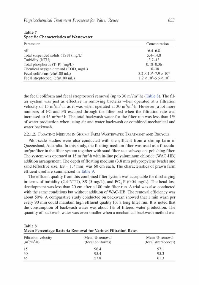
Table 7Specific Characteristics of Wastewater
Parameter Concentration
pH 6.4–6.8Total suspended solids (TSS) (mg/L) 5.4–14.8Turbidity (NTU) 3.7–13Total phosphorus (T- P) (mg/L) 0.18–0.36Chemical oxygen demand (COD, mg/L) 10–38Fecal coliforms (cfu/100 mL) 3.2 × 10³–7.9 × 10⁴
Fecal streptococci (cfu/100 mL) 1.2 × 10²-6.6 × 10³
Table 8Mean Percentage Bacteria Removal for Various Filtration Rates
Filtration velocity Mean % removal Mean % removal(m3/m2.h) (fecal coliforms) (fecal streptococci)
15 96.4 97.130 95.4 95.345 57.8 61.3
656 Saravanamuthu Vigneswaran et al.
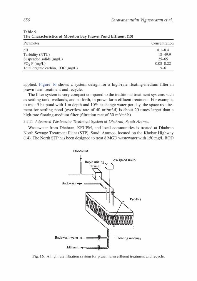
applied. Figure 16 shows a system design for a high-rate floating-medium filter inprawn farm treatment and recycle.
The filter system is very compact compared to the traditional treatment systems suchas settling tank, wetlands, and so forth, in prawn farm effluent treatment. For example,to treat 5 ha pond with 1 m depth and 10% exchange water per day, the space require-ment for settling pond (overflow rate of 40 m3/m2.d) is about 20 times larger than ahigh-rate floating-medium filter (filtration rate of 30 m3/m2.h)
2.2.2. Advanced Wastewater Treatment System at Dhahran, Saudi Aramco
Wastewater from Dhahran, KFUPM, and local communities is treated at DhahranNorth Sewage Treatment Plant (STP), Saudi Aramco, located on the Khobar Highway(14). The North STP has been designed to treat 8 MGD wastewater with 150 mg/L BOD
Table 9The Characteristics of Moreton Bay Prawn Pond Effluent (13)
Parameter Concentration
pH 8.1–8.4Turbidity (NTU) 18–49.9Suspended solids (mg/L) 25–65PO4-P (mg/L) 0.08–0.22Total organic carbon, TOC (mg/L) 5–6
Fig. 16. A high rate filtration system for prawn farm effluent treatment and recycle.
Physicochemical Treatment Processes for Water Reuse 657
(biochemical oxygen demand). The treatment processes include bar screen, grit cham-ber, Parshall flume, activated-sludge aeration tank with 13 h hydraulic detention time,final setting tank, effluent holding tank, and chlorine contact tank with residual chlorineof 2 mg/L. Sludge is treated at aerobic sludge digesters and digested sludge is pumpedto sludge drying beds for drying by sun. Since Saudi Arabia is very hot country with alot of sunshine, drying beds are ideal for sludge treatment. Dried sludge is disposed ata landfill. The effluent from treatment plant is pumped to percolation field by a 9 milepipeline. The treatment processes at the percolation filed consist of percolation, evapo-transpiration, and advanced wastewater-treatment system.
The flow to the advanced wastewater-treatment plant is 3.3 MGD. The plant is usedto upgrade secondary effluent produced from Dhahran North Sewage Treatment Plantto meet unrestricted effluent standards for irrigation. The treatment processes includecoagulation with alum and are followed by flocculation, sedimentation tank, rapid sandfilters, and disinfection with chlorine with free chlorine residual of 1 mg/L. The treatedeffluent is reused for irrigation for watering lawns of homes, common greenbelt areas,recreational grounds, and roadside medians.
2.2.3. Application of Ion-Exchange Process
Ion-exchange process is commonly used to remove hardness (polyvalent cations),iron, and manganese from drinking water supply. It can be used to remove and/orrecover many different types of ionic chemical species from the industrial wastewater(such as chromium and nickel from metal-plating wastewater). Ion-exchange processcan also be used in municipal wastewater-treatment system to remove nutrients (nitro-gen and phosphorus) and to demineralize the effluent for reuse purpose.
The ion-exchange system can be operated in one of the following modes: (a) batch,(b) fixed bed, (c) fluidized bed, and (d) continuous feed. Of these four modes, the fixed-bed system is the most commonly used.
A typical fixed-bed operating cycle consists of four steps: (a) service, (b) back-wash, (c) regeneration, and (d) rinse. The service life of the fixed-bed ion-exchangesystem can be evaluated from the effluent curve or breakthrough curve. Backwash isprovided to break up resin clumps and to remove finely divided suspended materialsentrapped in the resin. It also eliminates gas pockets and restratifies the resin bed toensure a uniform distribution of flow during service. Regeneration is provided to dis-place ion exchanged during the service run and to return the resin to its initialexchange capacity or to any other desired level depending on the amount of regen-erant used. In general, mineral acids and alkalies are used to regenerate cationexchange resins and anion exchange resins, respectively. After the regeneration step,the ion-exchange resin must be rinsed free of excess regenerant before being putback into service
Ion exchange is preferable to chemical precipitation for the water-softening processwhen raw water contains low color and turbidity level, hardness is largely not associ-ated with alkalinity (i.e., noncarbonate hardness is substantial), and hardness levelsvary. Most widely used system for water softening is a continuous-flow fixed-bed col-umn using a strong cationic resin in the sodium form, and the regeneration is done byNaCl (salt) solution.
Typical design criteria for a water softening resin system are:
Service flow rate: 12.5–20 m3/m2.hBackwash rate: 50–70% expansion of resin bedRegeneration: Regeneration solution concentration: 2–10 %; contact time: 30 min(2.5–5 m3/m2.h)Rinsing: 1.5–3 m3 of water/m3 of resin volumeBed depth: 75 cm minimumFree board: 50–75% of bed depth
3. MEMBRANE PROCESSES
3.1. Principle3.1.1. General
Membrane processes used in wastewater treatment can be categorized into fourclasses according to the size of particles that can be retained, namely, reverse osmosis(RO), ultrafiltration (UF), microfiltration (MF), and electrodialysis (ED). ED is aproven process for desalting brackish water. RO is also used extensively in desaltingapplications. It has an added advantage of being able to remove many organic com-pounds in addition to ionic species and microorganisms. The UF and MF techniques areuseful in removing macromolecules, colloids, and suspended solids.
Filters and membranes differ in the mechanism by which the solute is retained.Filters, such as paper, rely on having the particles trapped within the fibrous networkcomposing them, which eventually results in a decreasing flux rate due to plugging.Sand filters separate the solid particles through particle transport and attachment ontothe filter grain. Membranes, on the other hand, rely on the discreteness of the pore sizeopening in contact with the feed solution and the porous substructure under the thinskin. It is unlikely that particles will become trapped within the membranes. The abil-ity of membranes to reject macromolecules is based on the sieve mechanism. The sizeand shape of the macromolecule are important factors that determine whether themolecule will pass through the membrane.
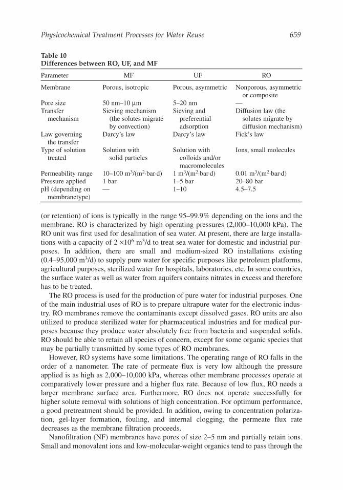
The ability of membranes to separate ions from water depends not only on the poresize, but also on the surface adsorption phenomena. For instance, it is observed thatabove 97% of salt is rejected in RO membrane processes, although there is no majormolecular size difference between water and common ions found in sea water. The highrejection occurs, in this case, due to the repulsion of ions away from the membranes,and the preferential adsorption of water molecules on the membrane surface. The pres-sure applied on the feed forces water through the membrane while retaining the solutein the bulk solution. Membrane processes are chosen according to the size range ofsolutes in the solution. Table 10 shows the operating conditions of membrane processes.
3.1.2. Reverse Osmosis and Nanofiltration
Reverse osmosis (RO) is based on the well-known phenomenon of osmosis, whichoccurs when two solutions of different concentrations are separated by a semipermeablemembrane. In this process, pressure is applied on the side of the concentrated solutionto reverse the natural osmotic flow. The thin RO membranes are essentially nonporous,and they preferentially pass water and retain most solutes including ions. The rejection
658 Saravanamuthu Vigneswaran et al.
Physicochemical Treatment Processes for Water Reuse 659
(or retention) of ions is typically in the range 95–99.9% depending on the ions and themembrane. RO is characterized by high operating pressures (2,000–10,000 kPa). TheRO unit was first used for desalination of sea water. At present, there are large installa-tions with a capacity of 2 ×10⁶ m3/d to treat sea water for domestic and industrial pur-poses. In addition, there are small and medium-sized RO installations existing(0.4–95,000 m3/d) to supply pure water for specific purposes like petroleum platforms,agricultural purposes, sterilized water for hospitals, laboratories, etc. In some countries,the surface water as well as water from aquifers contains nitrates in excess and thereforehas to be treated.
The RO process is used for the production of pure water for industrial purposes. Oneof the main industrial uses of RO is to prepare ultrapure water for the electronic indus-try. RO membranes remove the contaminants except dissolved gases. RO units are alsoutilized to produce sterilized water for pharmaceutical industries and for medical pur-poses because they produce water absolutely free from bacteria and suspended solids.RO should be able to retain all species of concern, except for some organic species thatmay be partially transmitted by some types of RO membranes.
However, RO systems have some limitations. The operating range of RO falls in theorder of a nanometer. The rate of permeate flux is very low although the pressureapplied is as high as 2,000–10,000 kPa, whereas other membrane processes operate atcomparatively lower pressure and a higher flux rate. Because of low flux, RO needs alarger membrane surface area. Furthermore, RO does not operate successfully forhigher solute removal with solutions of high concentration. For optimum performance,a good pretreatment should be provided. In addition, owing to concentration polariza-tion, gel-layer formation, fouling, and internal clogging, the permeate flux ratedecreases as the membrane filtration proceeds.
Nanofiltration (NF) membranes have pores of size 2–5 nm and partially retain ions.Small and monovalent ions and low-molecular-weight organics tend to pass through the
Table 10Differences between RO, UF, and MF
Parameter MF UF RO
Membrane Porous, isotropic Porous, asymmetric Nonporous, asymmetricor composite
Pore size 50 nm–10 μm 5–20 nm —Transfer Sieving mechanism Sieving and Diffusion law (the
mechanism (the solutes migrate preferential solutes migrate by by convection) adsorption diffusion mechanism)
Law governing Darcy’s law Darcy’s law Fick’s lawthe transfer
Type of solution Solution with Solution with Ions, small moleculestreated solid particles colloids and/or
macromoleculesPermeability range 10–100 m3/(m2.bar.d) 1 m3/(m2.bar.d) 0.01 m3/(m2.bar.d)Pressure applied 1 bar 1–5 bar 20–80 barpH (depending on — 1–10 4.5–7.5
membranetype)
660 Saravanamuthu Vigneswaran et al.
membrane. NF membranes usually have significantly higher water permeability thanRO membranes and operate at lower pressures, typically 700–3,000 kPa (15).
2.1.3. Ultrafiltration
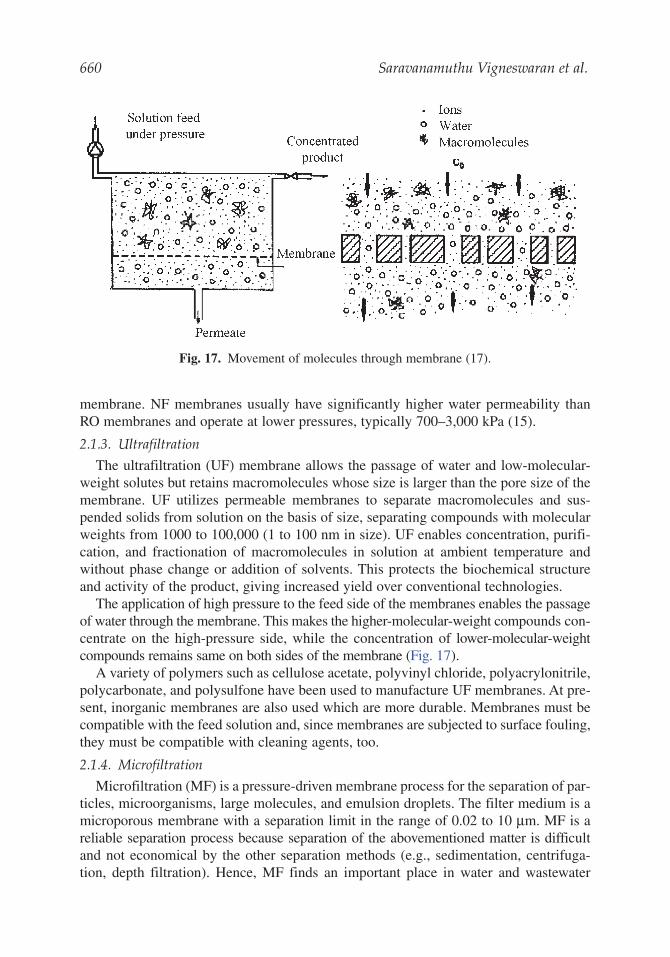
The ultrafiltration (UF) membrane allows the passage of water and low-molecular-weight solutes but retains macromolecules whose size is larger than the pore size of themembrane. UF utilizes permeable membranes to separate macromolecules and sus-pended solids from solution on the basis of size, separating compounds with molecularweights from 1000 to 100,000 (1 to 100 nm in size). UF enables concentration, purifi-cation, and fractionation of macromolecules in solution at ambient temperature andwithout phase change or addition of solvents. This protects the biochemical structureand activity of the product, giving increased yield over conventional technologies.
The application of high pressure to the feed side of the membranes enables the passageof water through the membrane. This makes the higher-molecular-weight compounds con-centrate on the high-pressure side, while the concentration of lower-molecular-weightcompounds remains same on both sides of the membrane (Fig. 17).
A variety of polymers such as cellulose acetate, polyvinyl chloride, polyacrylonitrile,polycarbonate, and polysulfone have been used to manufacture UF membranes. At pre-sent, inorganic membranes are also used which are more durable. Membranes must becompatible with the feed solution and, since membranes are subjected to surface fouling,they must be compatible with cleaning agents, too.
2.1.4. Microfiltration
Microfiltration (MF) is a pressure-driven membrane process for the separation of par-ticles, microorganisms, large molecules, and emulsion droplets. The filter medium is amicroporous membrane with a separation limit in the range of 0.02 to 10 μm. MF is areliable separation process because separation of the abovementioned matter is difficultand not economical by the other separation methods (e.g., sedimentation, centrifuga-tion, depth filtration). Hence, MF finds an important place in water and wastewater
Fig. 17. Movement of molecules through membrane (17).
Physicochemical Treatment Processes for Water Reuse 661
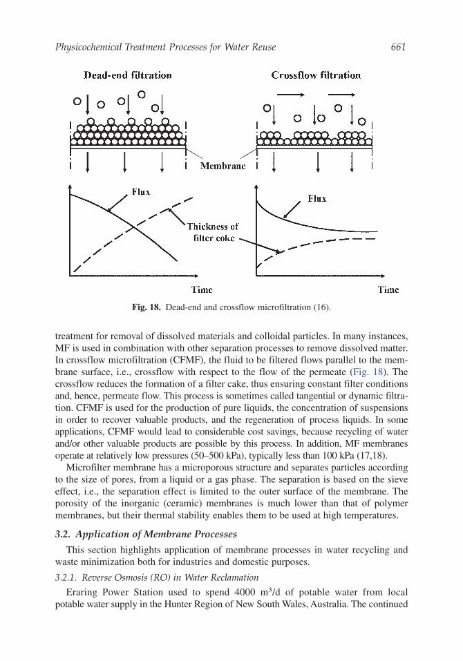
treatment for removal of dissolved materials and colloidal particles. In many instances,MF is used in combination with other separation processes to remove dissolved matter.In crossflow microfiltration (CFMF), the fluid to be filtered flows parallel to the mem-brane surface, i.e., crossflow with respect to the flow of the permeate (Fig. 18). Thecrossflow reduces the formation of a filter cake, thus ensuring constant filter conditionsand, hence, permeate flow. This process is sometimes called tangential or dynamic filtra-tion. CFMF is used for the production of pure liquids, the concentration of suspensionsin order to recover valuable products, and the regeneration of process liquids. In someapplications, CFMF would lead to considerable cost savings, because recycling of waterand/or other valuable products are possible by this process. In addition, MF membranesoperate at relatively low pressures (50–500 kPa), typically less than 100 kPa (17,18).
Microfilter membrane has a microporous structure and separates particles accordingto the size of pores, from a liquid or a gas phase. The separation is based on the sieveeffect, i.e., the separation effect is limited to the outer surface of the membrane. Theporosity of the inorganic (ceramic) membranes is much lower than that of polymermembranes, but their thermal stability enables them to be used at high temperatures.
3.2. Application of Membrane Processes
This section highlights application of membrane processes in water recycling andwaste minimization both for industries and domestic purposes.
3.2.1. Reverse Osmosis (RO) in Water Reclamation
Eraring Power Station used to spend 4000 m3/d of potable water from localpotable water supply in the Hunter Region of New South Wales, Australia. The continued
Fig. 18. Dead-end and crossflow microfiltration (16).
662 Saravanamuthu Vigneswaran et al.
residential growth required an expansion of potable water infrastructure. But, there wereenvironmental issues, as construction of pipelines would have disturbed surroundingenvironmentally sensitive areas. Therefore, the expansion of potable water supplyinfrastructure was offset by replacing the potable water requirement of the EraringPower Station with the reclaimed water from a nearby Sewage Treatment Plant locatedat Dora Creek.
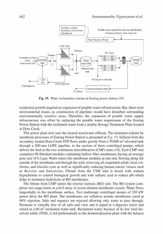
This power plant now uses the treated-wastewater effluent. The treatment scheme bymembrane processes of Eraring Power Station is presented in Fig. 19. Influent from thesecondary treated Dora Creek STP flows under gravity from a 70,000 m3 elevated tankthrough a 500 mm LDPE pipeline, to the suction of three centrifugal pumps, whichdeliver the feed to the two continuous microfiltration (CMF) units (19). Each CMF unitcomprises 90 filtration modules containing hollow fiber membranes having an averagepore size of 0.2 μm. Water enters the membrane modules at one end, flowing along theoutside of the membrane and through the wall, removing all suspended solids, fecal col-iforms, and Giardia cysts as well as significantly reducing human enteric viruses suchas Reovirus and Enterovirus. Filtrate from the CMF unit is dosed with sodiumhypochlorite to control biological growth and with sulfuric acid to reduce pH whichhelps to minimize hydrolysis of RO membranes.
The filtrate from CMF enters the reverse osmosis (RO) unit. The RO system com-prises two-stage trains in a 6×3 array of seven-element membrane vessels. Water flowstangentially to the membrane surface. Two multistage centrifugal pumps of 150 kWpower drive the RO plant. The membranes are cellulose acetate membranes rated at98% rejection. Salts and organics are rejected allowing only water to pass through.Permeate is virtually free of all salts and virus and is piped to a degasser tower andstored in a 60 m3 reclaimed water tank. Reclaimed water, because of its low total dis-solved solids (TDS), is fed preferentially to the demineralization plant with the balance
Fig. 19. Water reclamation scheme at Eraring power station (19).
Physicochemical Treatment Processes for Water Reuse 663
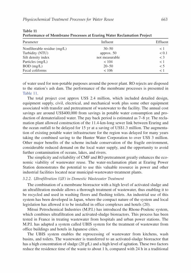
of water used for non-potable purposes around the power plant. RO rejects are disposedto the station’s ash dam. The performance of the membrane processes is presented inTable 11.
The total project cost approx US$ 2.4 million, which included detailed design,equipment supply, civil, electrical, and mechanical work plus some other equipmentassociated with transfer and pretreatment of wastewater to the facility. The annual costsavings are around US$400,000 from savings in potable water consumption and pro-duction of dematerialized water. The pay back period is estimated as 7–8 yr. The recla-mation plant allowed construction of the 11.4-km-long sewer link between Eraring andthe ocean outfall to be delayed for 15 yr at a saving of US$1.3 million. The augmenta-tion of existing potable water infrastructure for the region was delayed for many yearstaking the combined saving to the Hunter Water Corporation to over US$ 3 million.Other major benefits of the scheme include conservation of the fragile environment,considerable reduced demand on the local water supply, and the opportunity to avoidfurther contamination of oceans, lakes, and rivers.
The simplicity and reliability of CMF and RO pretreatment greatly enhances the eco-nomic viability of wastewater reuse. The water-reclamation plant at Eraring PowerStation demonstrates the potential to use this valuable resource in power and otherindustrial facilities located near municipal-wastewater-treatment plants.
3.2.2. Ultrafiltration (UF) in Domestic Wastewater Treatment
The combination of a membrane bioreactor with a high level of activated sludge andan ultrafiltration module allows a thorough treatment of wastewater, thus enabling it tobe recycled and used in washing floors and flushing toilets. An industrial use of thissystem has been developed in Japan, where the compact nature of the system and locallegislation has allowed it to be installed in office complexes and hotels (20).
Mitsui Petrochemical Industries (M.P.I.) has introduced the Rhone-Poulenc system,which combines ultrafiltration and activated-sludge bioreactors. This process has beentested in France in treating wastewater from hospitals and urban power stations. TheM.P.I. has adapted a system called UBIS system for the treatment of wastewater fromoffice buildings and hotels in Japanese cities.
The UBIS system enables the reprocessing of wastewater from kitchens, washbasins, and toilets. The wastewater is transferred to an activated-sludge bioreactor thathas a high concentration of sludge (20 g/L) and a high level of agitation. These two factorsreduce the residence time of the waste to about 1 h, compared with 24 h in a traditional
Table 11Performance of Membrane Processes at Eraring Water Reclamation Project
Parameter Influent Effluent
Nonfilterable residue (mg/L) 30–50 < 1Turbidity (NTU) approx. 50 < 0.1Silt density index not measurable < 3Particles (mg/L) < 104 < 1BOD (mg/L) 20–50 < 5Fecal coliforms < 106 < 1
system. Water passing through the membrane is free of suspended solids, viruses, andbacteria. This water is stored in a buffer tank where a small amount of sodium hypochlo-rite is added. It is then reused for flushing toilets.
The design of an ultrafiltration module using turbulence promoters allows very highfluxes over long periods. The flux varies between 100 and 120 L/m2 of membrane overa period of 45 d. Normal chemical cleaning is performed every 45 d and this cleaningprocedure requires approx 1–2 h. Electrical consumption is about 3 kwh/m3 of treatedwater. For instance, to treat 100 m3/d, a plant requires 45 m2 of floor space, and a mod-ule with 34 m2 of membrane area and a 6 m3 bioreactor. Compared to the conventionalprocess the UBIS system is very compact. The UBIS 20 system (capacity of 20 m3/d)has a bioreactor of 2.2 m3, buffer tank of 0.4 m3, wash tank 0.3 m3, and a membranearea of 7 m2; the overall dimensions are 2.0 m (high) × 4.5 m (long) × 2.0 m. The smallfoot-print allows installation in the basement of commercial or residential buildings. Forinstance, in treating 100 m3/d, the floor space saved is equivalent to 25 parking spaces.Operation and maintenance of the system is very simple and the system easily with-stands the change in load levels. The treated water is of very high quality and can bereused. Energy consumption and running costs together are low compared with tradi-tional processes because the treated water can be reused.
3.2.3. Ultrafiltration (UF) in Industrial Wastewater Treatment
Waste minimization at the source of waste generation point, is the correct approachand long-term solution to industrial pollution. It can be achieved by recycling wastes,process modification, product modification, substitution of raw and process materials,by-product recovery, etc. Membrane technology plays an important role in waste mini-mization. This section presents the membrane applications in industries such as paperand pulp, metal plating, cutting oil, textiles, and red meat abattoir industries. Many ofthese applications are examples of waste minimization with economic benefit.3.2.3.1. RECOVERY OF LIGNOSULFONATES FROM PULP INDUSTRY
Conventionally, an evaporator is used to recover lignosulfonates of all molecularweight fractions from black liquor. This material has little economical value.Ultrafiltration can be used to separate the high-molecular-weight lignosulfonates(which remain in the concentrate) from low-molecular-weight lignosulfonates (whichescape into the permeate). The recovery of high-molecular-weight lignosulfonates fromthe concentrate is not only economical but also eliminates part of the pollution problem.This material can be used to produce industrial products like dispersing agents and spin-ning solvent for polyacrylonlitrile fibers. The low-molecular-weight lignosulfonates caneasily be treated by conventional biological treatment. A pilot-scale study conductedusing inorganic ultrafilters of carbon zircona indicated that this process is technologi-cally and economically feasible. Operating conditions include temperatures in therange 90–140ºC and pressure of 750 kPa. Cleaning with acid/alkali was done onmonthly basis.3.2.3.2. RECOVERY OF PAINTS FROM METAL-PAINTING WASTEWATER
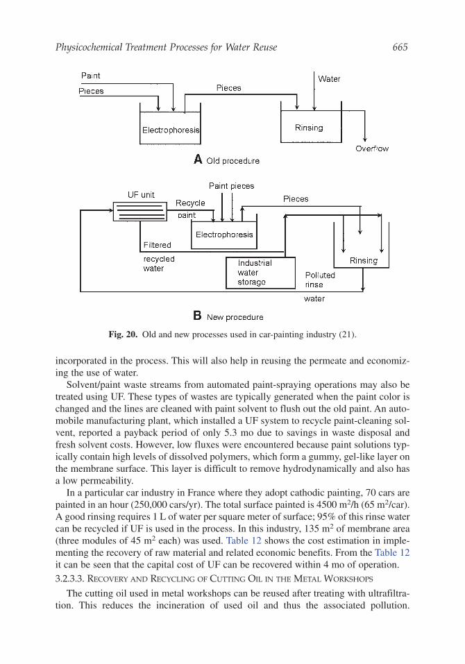
The ultrafiltration (UF) is used in the car painting industry especially where elec-trophoretic method of painting is adopted (Fig. 20). Around 25–45% of paint consumedgoes into the wastewater stream. This can be completely recovered if a UF system is
664 Saravanamuthu Vigneswaran et al.
Physicochemical Treatment Processes for Water Reuse 665
incorporated in the process. This will also help in reusing the permeate and economiz-ing the use of water.
Solvent/paint waste streams from automated paint-spraying operations may also betreated using UF. These types of wastes are typically generated when the paint color ischanged and the lines are cleaned with paint solvent to flush out the old paint. An auto-mobile manufacturing plant, which installed a UF system to recycle paint-cleaning sol-vent, reported a payback period of only 5.3 mo due to savings in waste disposal andfresh solvent costs. However, low fluxes were encountered because paint solutions typ-ically contain high levels of dissolved polymers, which form a gummy, gel-like layer onthe membrane surface. This layer is difficult to remove hydrodynamically and also hasa low permeability.
In a particular car industry in France where they adopt cathodic painting, 70 cars arepainted in an hour (250,000 cars/yr). The total surface painted is 4500 m2/h (65 m2/car).A good rinsing requires 1 L of water per square meter of surface; 95% of this rinse watercan be recycled if UF is used in the process. In this industry, 135 m2 of membrane area(three modules of 45 m2 each) was used. Table 12 shows the cost estimation in imple-menting the recovery of raw material and related economic benefits. From the Table 12it can be seen that the capital cost of UF can be recovered within 4 mo of operation.3.2.3.3. RECOVERY AND RECYCLING OF CUTTING OIL IN THE METAL WORKSHOPS
The cutting oil used in metal workshops can be reused after treating with ultrafiltra-tion. This reduces the incineration of used oil and thus the associated pollution.
Fig. 20. Old and new processes used in car-painting industry (21).
666 Saravanamuthu Vigneswaran et al.
Furthermore, energy savings can be made by the elimination of incineration. The relia-bility and longevity of the ultrafiltration membranes are satisfactory (they last more than2 yr if they are maintained properly). Table 13 shows the benefits of using ultrafiltrationto recover cutting oil in metal workshops. From the table, it is evident that, (a) pollutantdischarge is decreased by 95% due to the incorporation of ultrafiltration and (b) the rawmaterial requirement is reduced by 50%.3.2.3.4. RECOVERY OF BLUE COLORANT IN DYEING INDUSTRY
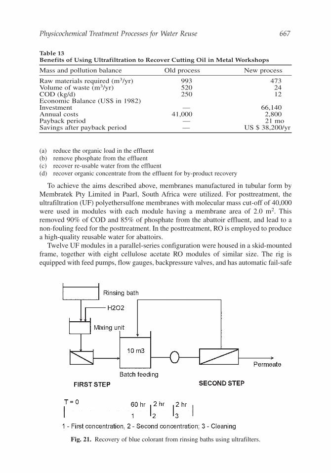
Recovery of blue colorant (indigo) from rinsing baths of jeans production units isanother example for waste minimization using ultrafiltration. Figure 21 shows the pro-cesses used to recover blue colorant from rinsing baths. With rinsing water, 10–20% ofthe color input is taken away. This corresponds to a color concentration of 0.1–0.8 g/L.By using an ultrafilter at 60ºC, this color can be concentrated up to 50 g/L and can berecycled directly.
As a first step, wastewater from the rinsing bath is mixed with hydrogen peroxide andpassed through the first ultrafilter continuously. When this process is carried out for 60h at the rate of 5 m3/h (permeate flux of 0.2 m /m2.h), 300 m3 of dye is treated at 0.5g/L concentration and 10 m3 of concentrate can be obtained with color concentration of15 g/L. In the second step, the 10 m3 of concentrate with 15 g/L concentration is passedthrough an ultrafilter for 2 h (permeate flux of 3.5 m3/h = 0.15 m /m2.h) and 3 m3 ofconcentrate is obtained at 50 g/L concentration. Thus every 60 hr, 150 kg of indigo isrecovered. The payback period for the ultrafiltration system is about 1 yr and, after this,the savings every year will be around US $ 400,000.3.2.3.5. UF AS A PRETREATMENT FOR RO IN THE RED MEAT ABATTOIR INDUSTRY
In South Africa, there are more than 300 registered abattoirs. They consume a sig-nificant quantity (>7,000,000 m3) of potable quality water every year and generate morethan 6,000,000 m3 of effluent per year, which generally goes into the municipal sewers.Therefore, an effluent treatment system was developed to:
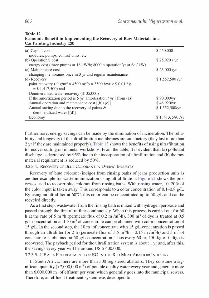
Table 12Economic Benefit in Implementing the Recovery of Raw Materials in aCar Painting Industry (20)
(a) Capital cost $ 450,000modules, pumps, control units, etc.
(b) Operational cost $ 25,920 / yrenergy cost (three pumps at 18 kW/h; 8000 h operation/yr at 6c / kW)
(c) Maintenance cost $ 23,000 /yrchanging membranes once in 3 yr and regular maintenance
(d) Recovery $ 1,552,500 /yrpaint recovery ( 9 g/m2 × 4500 m2/h × 3500 h/yr × $ 0.01 / g
= $ 1,417,500) andDemineralized water recovery ($135,000)If the amortization period is 5 yr, amortization / yr [ from (a)] $ 90,000/yrAnnual operation and maintenance cost [(b)+(c)] $ 48,920/yrAnnual saving due to the recovery of paints & $ 1,552,500/yr
demineralized water [(d)]Economy $ 1, 413, 580 /yr
Physicochemical Treatment Processes for Water Reuse 667
(a) reduce the organic load in the effluent(b) remove phosphate from the effluent(c) recover re-usable water from the effluent(d) recover organic concentrate from the effluent for by-product recovery
To achieve the aims described above, membranes manufactured in tubular form byMembratek Pty Limited in Paarl, South Africa were utilized. For posttreatment, theultrafiltration (UF) polyethersulfone membranes with molecular mass cut-off of 40,000were used in modules with each module having a membrane area of 2.0 m2. Thisremoved 90% of COD and 85% of phosphate from the abattoir effluent, and lead to anon-fouling feed for the posttreatment. In the posttreatment, RO is employed to producea high-quality reusable water for abattoirs.
Twelve UF modules in a parallel-series configuration were housed in a skid-mountedframe, together with eight cellulose acetate RO modules of similar size. The rig isequipped with feed pumps, flow gauges, backpressure valves, and has automatic fail-safe
Table 13Benefits of Using Ultrafiltration to Recover Cutting Oil in Metal Workshops
Mass and pollution balance Old process New process
Raw materials required (m3/yr) 993 473Volume of waste (m3/yr) 520 24COD (kg/d) 250 12Economic Balance (US$ in 1982)Investment — 66,140Annual costs 41,000 2,800Payback period — 21 moSavings after payback period — US $ 38,200/yr
Fig. 21. Recovery of blue colorant from rinsing baths using ultrafilters.
668 Saravanamuthu Vigneswaran et al.
cutouts on temperature, pressure, and pH (for RO). The capacity of UF train was 1000L filtrate/h and the capacity of RO train was 300–350 L of permeate/h. Table 14 sum-marizes the performance of the membrane system.
A cost comparison made based on a daily flow of 820 m3 indicated that UF and ROtreatment (capital cost of US$ 0.6 million and operating and maintenance cost of US$0.55 million) is more economical compared to the conventional treatment of anaerobicdigestion (capital cost of US$ 0.75 million and operating and maintenance cost of US$0.85 million). Apart from the cost considerations, membrane processes lead to highquality effluent.
3.2.4. Microfiltration (MF) in Domestic Wastewater Treatment
Wastewater treatment and reuse are important parts of our aqueous environmentalmanagement, and they provide huge opportunities for the use of membranes. Table 15presents water contaminants and typical removal range for membranes hybrid processes.3.2.4.1. WATER MINING PLANT AT CANBERRA, AUSTRALIA
The first Water Mining plant was opened in 1995 at Southwell Park in Canberra,Australia (Fig. 22). The project was to demonstrate the feasibility of effluent reuse inurban public access areas and to establish community acceptance. Although non-potable treated wastewater is used widely for landscape irrigation and golf courses, thiswas the first time it would irrigate public access land within urban Canberra. Thus theplant design focused on health issues, noise and odor control, and preservation of neigh-borhood amenity.
Table 14Performance of the Membrane System
Parameter (mg/L) Influent UF Effluent RO Effluent
COD 6000 42–60 2–3Soluble phosphorus 40 6 0.3
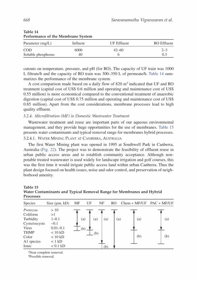
Table 15Water Contaminants and Typical Removal Range for Membranes and HybridProcesses
Species Size (μm, kD) MF UF NF RO Chem + MF/UF PAC + MF/UF
Protozoa > 10Coliform >1Turbidity 1–0.1 (a) (a) (a) (a) (a) (a)Cysts/oocysts ~0.1Virus 0.01–0.1 (b)THMP < 10 kD (b)Color < 10 kD (b) (b)A1 species < 1 kDIonic < 0.1 kD (b)
aNear complete removal.bPossible removal.
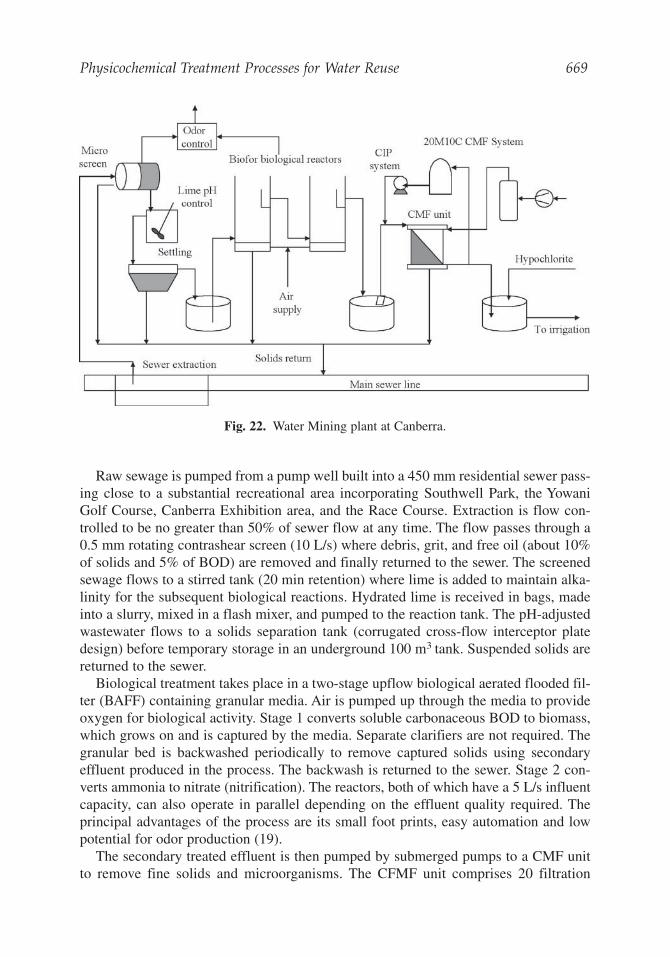
Physicochemical Treatment Processes for Water Reuse 669
Raw sewage is pumped from a pump well built into a 450 mm residential sewer pass-ing close to a substantial recreational area incorporating Southwell Park, the YowaniGolf Course, Canberra Exhibition area, and the Race Course. Extraction is flow con-trolled to be no greater than 50% of sewer flow at any time. The flow passes through a0.5 mm rotating contrashear screen (10 L/s) where debris, grit, and free oil (about 10%of solids and 5% of BOD) are removed and finally returned to the sewer. The screenedsewage flows to a stirred tank (20 min retention) where lime is added to maintain alka-linity for the subsequent biological reactions. Hydrated lime is received in bags, madeinto a slurry, mixed in a flash mixer, and pumped to the reaction tank. The pH-adjustedwastewater flows to a solids separation tank (corrugated cross-flow interceptor platedesign) before temporary storage in an underground 100 m3 tank. Suspended solids arereturned to the sewer.
Biological treatment takes place in a two-stage upflow biological aerated flooded fil-ter (BAFF) containing granular media. Air is pumped up through the media to provideoxygen for biological activity. Stage 1 converts soluble carbonaceous BOD to biomass,which grows on and is captured by the media. Separate clarifiers are not required. Thegranular bed is backwashed periodically to remove captured solids using secondaryeffluent produced in the process. The backwash is returned to the sewer. Stage 2 con-verts ammonia to nitrate (nitrification). The reactors, both of which have a 5 L/s influentcapacity, can also operate in parallel depending on the effluent quality required. Theprincipal advantages of the process are its small foot prints, easy automation and lowpotential for odor production (19).
The secondary treated effluent is then pumped by submerged pumps to a CMF unitto remove fine solids and microorganisms. The CFMF unit comprises 20 filtration
Fig. 22. Water Mining plant at Canberra.
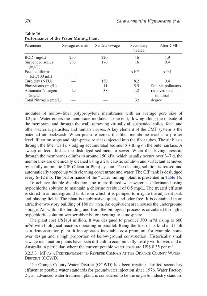
670 Saravanamuthu Vigneswaran et al.
modules of hollow-fiber polypropylene membranes with an average pore size of0.2 μm. Water enters the membrane modules at one end, flowing along the outside ofthe membrane and through the wall, removing virtually all suspended solids, fecal andother bacteria, parasites, and human viruses. A key element of the CMF system is thepatented air backwash. When pressure across the fiber membrane reaches a pre-setlevel, filtration stops and high-pressure air is injected into the fiber tubes. The air blaststhrough the fiber wall dislodging accumulated sediments sitting on the outer surface. Asweep of feed flushes the dislodged sediment to sewer. When the driving pressurethrough the membranes climbs to around 150 kPa, which usually occurs over 3–7 d, themembranes are chemically cleaned using a 2% caustic solution and surfactant achievedby a fully automatic CIP (Clean-in-Pipe) system. The cleaning solution is reused andautomatically topped up with cleaning concentrate and water. The CIP tank is desludgedevery 6–12 mo. The performance of the “water mining” plant is presented in Table 16.
To achieve double disinfection, the microfiltered wastewater is chlorinated usinghypochlorite solution to maintain a chlorine residual of 0.5 mg/L. The treated effluentis stored in an underground tank from which it is pumped to irrigate the adjacent parkand playing fields. The plant is unobtrusive, quiet, and odor free. It is contained in anattractive two-story building of 180 m2 area. An equivalent area houses the undergroundstorage. Air within the building and from the biological process is circulated through ahypochlorite solution wet scrubber before venting to atmosphere.
The plant cost US$1.4 million. It was designed to produce 300 m3/d rising to 600m3/d with biological reactors operating in parallel. Being the first of its kind and builtas a demonstration plant, it incorporates inevitable cost premium, for example, someover design and a high proportion of below-ground construction. Historically smallsewage reclamation plants have been difficult to economically justify world over, and inAustralia in particular, where the current potable water costs are US$ 0.35 per m3.3.2.3.3. MF AS A PRETREATMENT TO REVERSE OSMOSIS AT THE ORANGE COUNTY WATER
DISTRICT (OCWD)
The Orange County Water District (OCWD) has been treating clarified secondaryeffluent to potable water standards for groundwater injection since 1976. Water Factory21, an advanced water-treatment plant, is considered to be the de facto industry standard
Table 16Performance of the Water Mining Plant
Parameter Sewage ex-main Settled sewage Secondary After CMFtreated
BOD (mg/L) 250 220 16 1.9Suspended solids 230 170 16 0.4
(mg/L)Fecal coliforms — — <106 < 0.1
(cfu/100 mL)Turbidity (NTU) — 130 8.2 0.4Phosphorus (mg/L) — 11 5.5 Soluble pollutantsAmmonia-Nitrogen 29 38 1.2 removed to a
(mg/L) minimalTotal Nitrogen (mg/L) — — 32 degree
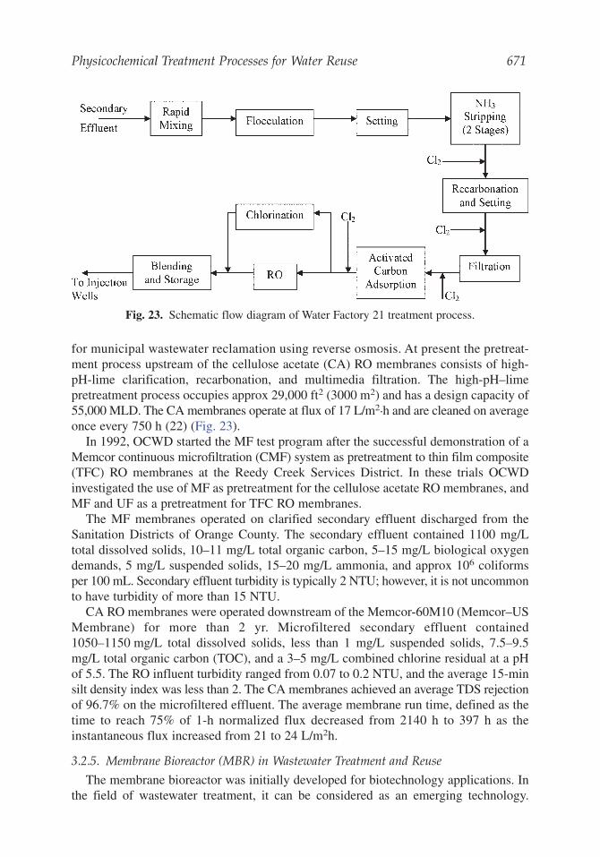
Physicochemical Treatment Processes for Water Reuse 671
for municipal wastewater reclamation using reverse osmosis. At present the pretreat-ment process upstream of the cellulose acetate (CA) RO membranes consists of high-pH-lime clarification, recarbonation, and multimedia filtration. The high-pH–limepretreatment process occupies approx 29,000 ft2 (3000 m2) and has a design capacity of55,000 MLD. The CA membranes operate at flux of 17 L/m2.h and are cleaned on averageonce every 750 h (22) (Fig. 23).
In 1992, OCWD started the MF test program after the successful demonstration of aMemcor continuous microfiltration (CMF) system as pretreatment to thin film composite(TFC) RO membranes at the Reedy Creek Services District. In these trials OCWDinvestigated the use of MF as pretreatment for the cellulose acetate RO membranes, andMF and UF as a pretreatment for TFC RO membranes.
The MF membranes operated on clarified secondary effluent discharged from theSanitation Districts of Orange County. The secondary effluent contained 1100 mg/Ltotal dissolved solids, 10–11 mg/L total organic carbon, 5–15 mg/L biological oxygendemands, 5 mg/L suspended solids, 15–20 mg/L ammonia, and approx 106 coliformsper 100 mL. Secondary effluent turbidity is typically 2 NTU; however, it is not uncommonto have turbidity of more than 15 NTU.
CA RO membranes were operated downstream of the Memcor-60M10 (Memcor–USMembrane) for more than 2 yr. Microfiltered secondary effluent contained1050–1150 mg/L total dissolved solids, less than 1 mg/L suspended solids, 7.5–9.5mg/L total organic carbon (TOC), and a 3–5 mg/L combined chlorine residual at a pHof 5.5. The RO influent turbidity ranged from 0.07 to 0.2 NTU, and the average 15-minsilt density index was less than 2. The CA membranes achieved an average TDS rejectionof 96.7% on the microfiltered effluent. The average membrane run time, defined as thetime to reach 75% of 1-h normalized flux decreased from 2140 h to 397 h as theinstantaneous flux increased from 21 to 24 L/m2h.
3.2.5. Membrane Bioreactor (MBR) in Wastewater Treatment and Reuse
The membrane bioreactor was initially developed for biotechnology applications. Inthe field of wastewater treatment, it can be considered as an emerging technology.
Fig. 23. Schematic flow diagram of Water Factory 21 treatment process.
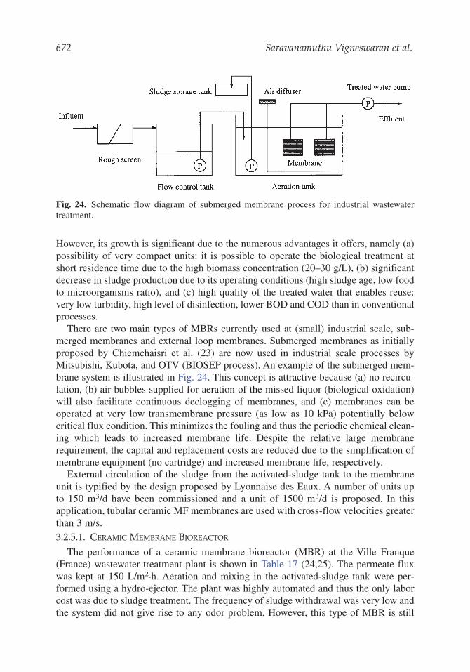
672 Saravanamuthu Vigneswaran et al.
However, its growth is significant due to the numerous advantages it offers, namely (a)possibility of very compact units: it is possible to operate the biological treatment atshort residence time due to the high biomass concentration (20–30 g/L), (b) significantdecrease in sludge production due to its operating conditions (high sludge age, low foodto microorganisms ratio), and (c) high quality of the treated water that enables reuse:very low turbidity, high level of disinfection, lower BOD and COD than in conventionalprocesses.
There are two main types of MBRs currently used at (small) industrial scale, sub-merged membranes and external loop membranes. Submerged membranes as initiallyproposed by Chiemchaisri et al. (23) are now used in industrial scale processes byMitsubishi, Kubota, and OTV (BIOSEP process). An example of the submerged mem-brane system is illustrated in Fig. 24. This concept is attractive because (a) no recircu-lation, (b) air bubbles supplied for aeration of the missed liquor (biological oxidation)will also facilitate continuous declogging of membranes, and (c) membranes can beoperated at very low transmembrane pressure (as low as 10 kPa) potentially belowcritical flux condition. This minimizes the fouling and thus the periodic chemical clean-ing which leads to increased membrane life. Despite the relative large membranerequirement, the capital and replacement costs are reduced due to the simplification ofmembrane equipment (no cartridge) and increased membrane life, respectively.
External circulation of the sludge from the activated-sludge tank to the membraneunit is typified by the design proposed by Lyonnaise des Eaux. A number of units upto 150 m3/d have been commissioned and a unit of 1500 m3/d is proposed. In thisapplication, tubular ceramic MF membranes are used with cross-flow velocities greaterthan 3 m/s.3.2.5.1. CERAMIC MEMBRANE BIOREACTOR
The performance of a ceramic membrane bioreactor (MBR) at the Ville Franque(France) wastewater-treatment plant is shown in Table 17 (24,25). The permeate fluxwas kept at 150 L/m2.h. Aeration and mixing in the activated-sludge tank were per-formed using a hydro-ejector. The plant was highly automated and thus the only laborcost was due to sludge treatment. The frequency of sludge withdrawal was very low andthe system did not give rise to any odor problem. However, this type of MBR is still
Fig. 24. Schematic flow diagram of submerged membrane process for industrial wastewatertreatment.
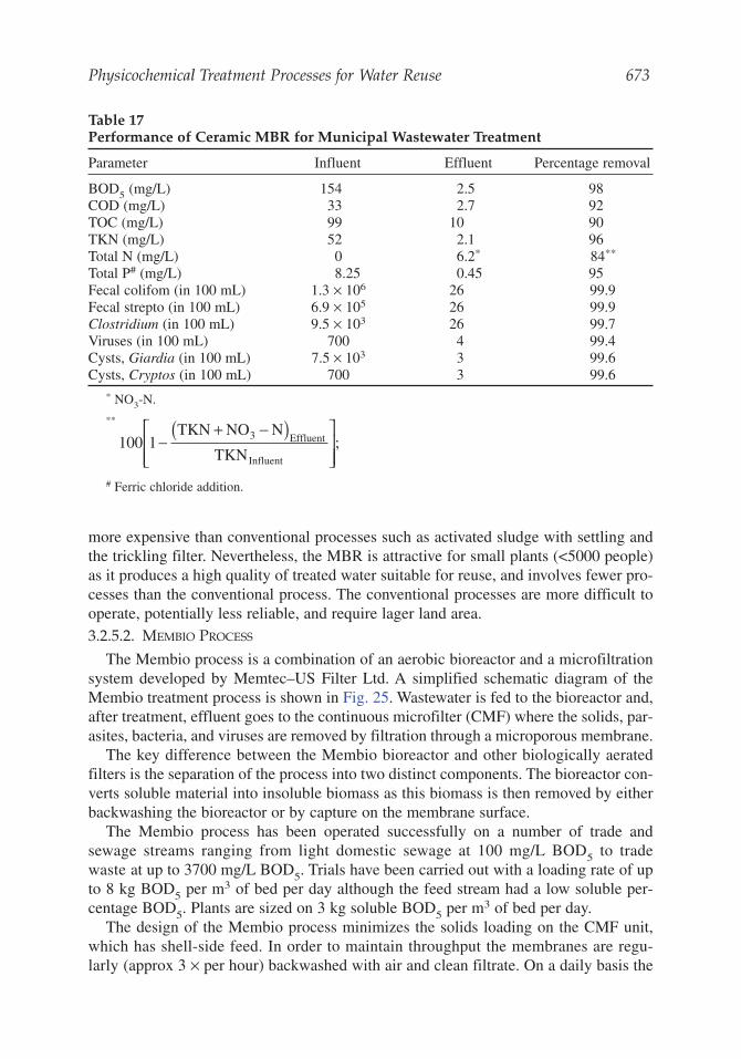
Physicochemical Treatment Processes for Water Reuse 673
more expensive than conventional processes such as activated sludge with settling andthe trickling filter. Nevertheless, the MBR is attractive for small plants (<5000 people)as it produces a high quality of treated water suitable for reuse, and involves fewer pro-cesses than the conventional process. The conventional processes are more difficult tooperate, potentially less reliable, and require lager land area.3.2.5.2. MEMBIO PROCESS
The Membio process is a combination of an aerobic bioreactor and a microfiltrationsystem developed by Memtec–US Filter Ltd. A simplified schematic diagram of theMembio treatment process is shown in Fig. 25. Wastewater is fed to the bioreactor and,after treatment, effluent goes to the continuous microfilter (CMF) where the solids, par-asites, bacteria, and viruses are removed by filtration through a microporous membrane.
The key difference between the Membio bioreactor and other biologically aeratedfilters is the separation of the process into two distinct components. The bioreactor con-verts soluble material into insoluble biomass as this biomass is then removed by eitherbackwashing the bioreactor or by capture on the membrane surface.
The Membio process has been operated successfully on a number of trade andsewage streams ranging from light domestic sewage at 100 mg/L BOD5 to tradewaste at up to 3700 mg/L BOD5. Trials have been carried out with a loading rate of upto 8 kg BOD5 per m3 of bed per day although the feed stream had a low soluble per-centage BOD5. Plants are sized on 3 kg soluble BOD5 per m3 of bed per day.
The design of the Membio process minimizes the solids loading on the CMF unit,which has shell-side feed. In order to maintain throughput the membranes are regu-larly (approx 3 × per hour) backwashed with air and clean filtrate. On a daily basis the
Table 17Performance of Ceramic MBR for Municipal Wastewater Treatment
Parameter Influent Effluent Percentage removal
BOD5 (mg/L) 154 2.5 98COD (mg/L) 33 2.7 92TOC (mg/L) 99 10 90TKN (mg/L) 52 2.1 96Total N (mg/L) 0 6.2* 84**
Total P# (mg/L) 8.25 0.45 95Fecal colifom (in 100 mL) 1.3 × 10⁶ 26 99.9Fecal strepto (in 100 mL) 6.9 × 10⁵ 26 99.9Clostridium (in 100 mL) 9.5 × 10³ 26 99.7Viruses (in 100 mL) 700 4 99.4Cysts, Giardia (in 100 mL) 7.5 × 10³ 3 99.6Cysts, Cryptos (in 100 mL) 700 3 99.6
* NO3-N.
**
# Ferric chloride addition.
100 1−+ −( )⎡
⎣⎢⎢
⎤
⎦⎥⎥
TKN NO N
TKN3 Effluent
Influent
;
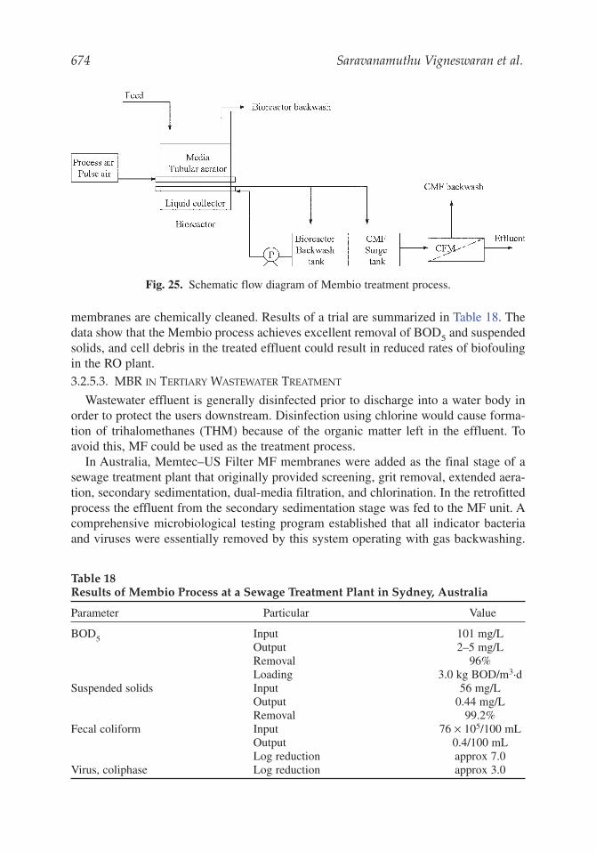
674 Saravanamuthu Vigneswaran et al.
membranes are chemically cleaned. Results of a trial are summarized in Table 18. Thedata show that the Membio process achieves excellent removal of BOD5 and suspendedsolids, and cell debris in the treated effluent could result in reduced rates of biofoulingin the RO plant.3.2.5.3. MBR IN TERTIARY WASTEWATER TREATMENT
Wastewater effluent is generally disinfected prior to discharge into a water body inorder to protect the users downstream. Disinfection using chlorine would cause forma-tion of trihalomethanes (THM) because of the organic matter left in the effluent. Toavoid this, MF could be used as the treatment process.
In Australia, Memtec–US Filter MF membranes were added as the final stage of asewage treatment plant that originally provided screening, grit removal, extended aera-tion, secondary sedimentation, dual-media filtration, and chlorination. In the retrofittedprocess the effluent from the secondary sedimentation stage was fed to the MF unit. Acomprehensive microbiological testing program established that all indicator bacteriaand viruses were essentially removed by this system operating with gas backwashing.
Fig. 25. Schematic flow diagram of Membio treatment process.
Table 18Results of Membio Process at a Sewage Treatment Plant in Sydney, Australia
Parameter Particular Value
BOD5 Input 101 mg/LOutput 2–5 mg/LRemoval 96%Loading 3.0 kg BOD/m3.d
Suspended solids Input 56 mg/LOutput 0.44 mg/LRemoval 99.2%
Fecal coliform Input 76 × 105/100 mLOutput 0.4/100 mLLog reduction approx 7.0
Virus, coliphase Log reduction approx 3.0
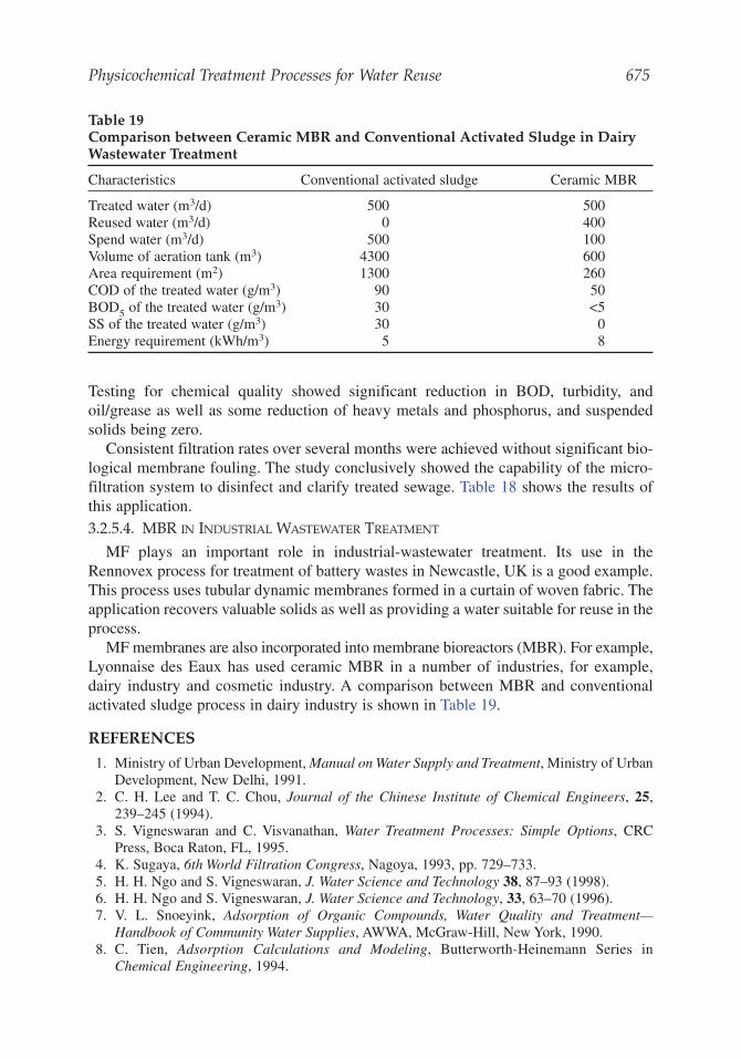
Physicochemical Treatment Processes for Water Reuse 675
Testing for chemical quality showed significant reduction in BOD, turbidity, andoil/grease as well as some reduction of heavy metals and phosphorus, and suspendedsolids being zero.
Consistent filtration rates over several months were achieved without significant bio-logical membrane fouling. The study conclusively showed the capability of the micro-filtration system to disinfect and clarify treated sewage. Table 18 shows the results ofthis application.3.2.5.4. MBR IN INDUSTRIAL WASTEWATER TREATMENT
MF plays an important role in industrial-wastewater treatment. Its use in theRennovex process for treatment of battery wastes in Newcastle, UK is a good example.This process uses tubular dynamic membranes formed in a curtain of woven fabric. Theapplication recovers valuable solids as well as providing a water suitable for reuse in theprocess.
MF membranes are also incorporated into membrane bioreactors (MBR). For example,Lyonnaise des Eaux has used ceramic MBR in a number of industries, for example,dairy industry and cosmetic industry. A comparison between MBR and conventionalactivated sludge process in dairy industry is shown in Table 19.
REFERENCES
1. Ministry of Urban Development, Manual on Water Supply and Treatment, Ministry of UrbanDevelopment, New Delhi, 1991.
2. C. H. Lee and T. C. Chou, Journal of the Chinese Institute of Chemical Engineers, 25,239–245 (1994).
3. S. Vigneswaran and C. Visvanathan, Water Treatment Processes: Simple Options, CRCPress, Boca Raton, FL, 1995.
4. K. Sugaya, 6th World Filtration Congress, Nagoya, 1993, pp. 729–733.5. H. H. Ngo and S. Vigneswaran, J. Water Science and Technology 38, 87–93 (1998).6. H. H. Ngo and S. Vigneswaran, J. Water Science and Technology, 33, 63–70 (1996).7. V. L. Snoeyink, Adsorption of Organic Compounds, Water Quality and Treatment—
Handbook of Community Water Supplies, AWWA, McGraw-Hill, New York, 1990.8. C. Tien, Adsorption Calculations and Modeling, Butterworth-Heinemann Series in
Chemical Engineering, 1994.
Table 19Comparison between Ceramic MBR and Conventional Activated Sludge in DairyWastewater Treatment
Characteristics Conventional activated sludge Ceramic MBR
Treated water (m3/d) 500 500Reused water (m3/d) 0 400Spend water (m3/d) 500 100Volume of aeration tank (m3) 4300 600Area requirement (m2) 1300 260COD of the treated water (g/m3) 90 50BOD5 of the treated water (g/m3) 30 <5SS of the treated water (g/m3) 30 0Energy requirement (kWh/m3) 5 8
9. G. McKay, Use of Adsorbents for the Removal of Pollutants from Wastewaters, CRC Press,Boca Raton, FL, 1995.
10. D. Cooney, Adsorption Design for Wastewater Treatment, Lewis Publishers, Boca Raton,FL, 1998.
11. S. Vigneswaran and R. Ben Aim (eds.), Water, Wastewater and Sludge Filtration, CRCPress, Boca Raton, FL, 1989.
12. P. Dillon, Water: Journal of Australian Water Association, 28, 18–21 (2001).13. S. Vigneswaran, H. H. Ngo, J. Hu, and D. Y. Kwon, AIT Civil and Environmental
Engineering Conference, New Frontiers & Challenges, Bangkok, 1999, Vol.1, pp. 1–7.14. Y. T. Hung, OCEESA J, 19, 48–53 (2002).15. J. S. Taylor and E. P. Jacobs, Water Treatment Membrane Processes (Mallevialle, J. Odendaal
P. E., and Wiesner M. R. (eds.)), McGraw-Hill, New York, 1996, pp. 9.1–9.70.16. S. Rippenger, Water, Wastewater, and Sludge Filtration,(Vigneswaran, S. and Ben Aim, R.
eds.), CRC Press, Boca Raton, FL, 1989, pp. 173–190.17. S. Vigneswaran, B. Vigneswaran, and R. Ben Aim, Environmental Sanitation Reviews 31,
5–46 (1991).18. J. G. Jacangelo and C. A. Buckley, Water Treatment Membrane Processes (Mallevialle,
J., Odendaal, P. E., and Weisner, M. R., eds.). Mc Graw-Hill., New York, 1996, pp. 11.1–11.39.19. Bulletins A 2047, A 2051, A 2052, A 2056, and A 2069, Memtec-US Filter Technical
Bulletins.20. M. Roulet, Selected Topics on Clean Technology, (Vigneswaran, S., Mino, T., and
Polprasert, C. eds.), Asian Institute of Technology, Bangkok, 1989, pp. 171–17821. M. R. Overcash, Techniques for Industrial Pollution Prevention—A Compendium for
Hazardous and Non-hazardous Waste Minimization, Lewis Publishers, Inc., Chelsea, MI,1986.
22. G. L. Leslie, W. R. Dunivin, P. Gabillet, S. R. Conklin, W. R. Mills, and R. G. Sudar, Pilottesting of microfiltration and ultrafiltration upstream of reverse osmosis during reclamationof municipal wastewater, 1996 Technical Report (unpublished paper), 1996.
23. C. Chiemchaisri, K. Yamamoto, and S. Vigneswaran, J. Water Science and Technology 27,171–178 (1993).
24. E. Trouve, L. Detons, G. Greaugey, and J. Manem, Station d’epuration BRM de ville-granque. Actes des 12emes Jounees Information Eaux - JIE 96, Portiers, 60-1–60-2, 1996.
25. V. Urbain, E. Trouve, and J. Manem, Proceedings of the 67thAnnual Conference andExposition WEFTEC 94, Chicago, IL, 1994, pp. 317–323.
676 Saravanamuthu Vigneswaran et al.


![[BLM14] BIC_Pham Huu Tam](https://img.pdfslide.us/doc/110x75/558cf44fd8b42a830f8b4671/blm14-bicpham-huu-tam.jpg)