Embed Size (px)
Citation preview

ENVIRONMENTAL EFFECTS ON AN INTEGRAL BRIDGE IN SOUTH AFRICA
Sarah Skorpen & Mohamed Parak
• South African National Roads Agency
• Project Engineer - Structures

ACKNOWLEDGEMENTS
• Client: SANRAL
• Consultant: Mott MacDonald
• PHD Research: Ms. Sarah Skorpen, PrEng
University of Pretoria
• Contractor: Aveng Grinaker-LTA

*
Reinforced Concrete
Length: 90m
Width: 14.5m
5 Spans: 20.7m
Height: 5m
VAN ZYLSPRUIT BRIDGE
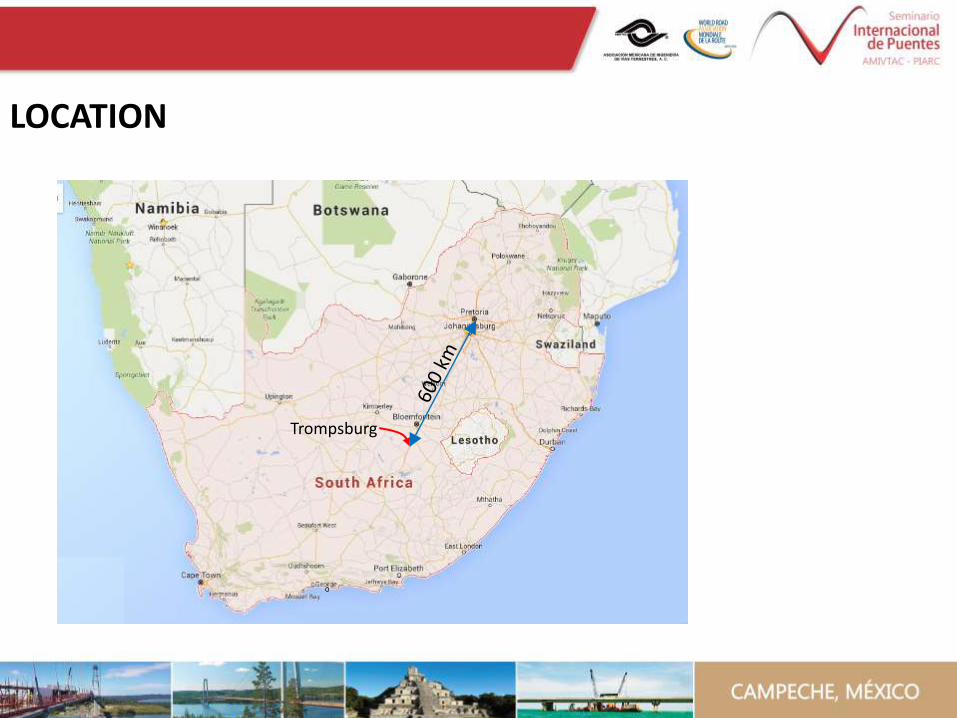
LOCATION
Trompsburg

PURPOSE OF THE BRIDGE MONITORING
• Integral bridge behaviour in a South African context.
• Environmental factors on the behaviour of long integral bridge taking the South African climate (hot and dry) into account.
• Earth pressure response behind the abutment over time.
• Compare assumed bridge behaviour (i.e. bridge analysis) to actual measured behaviour and note trends / behaviour patterns.
*
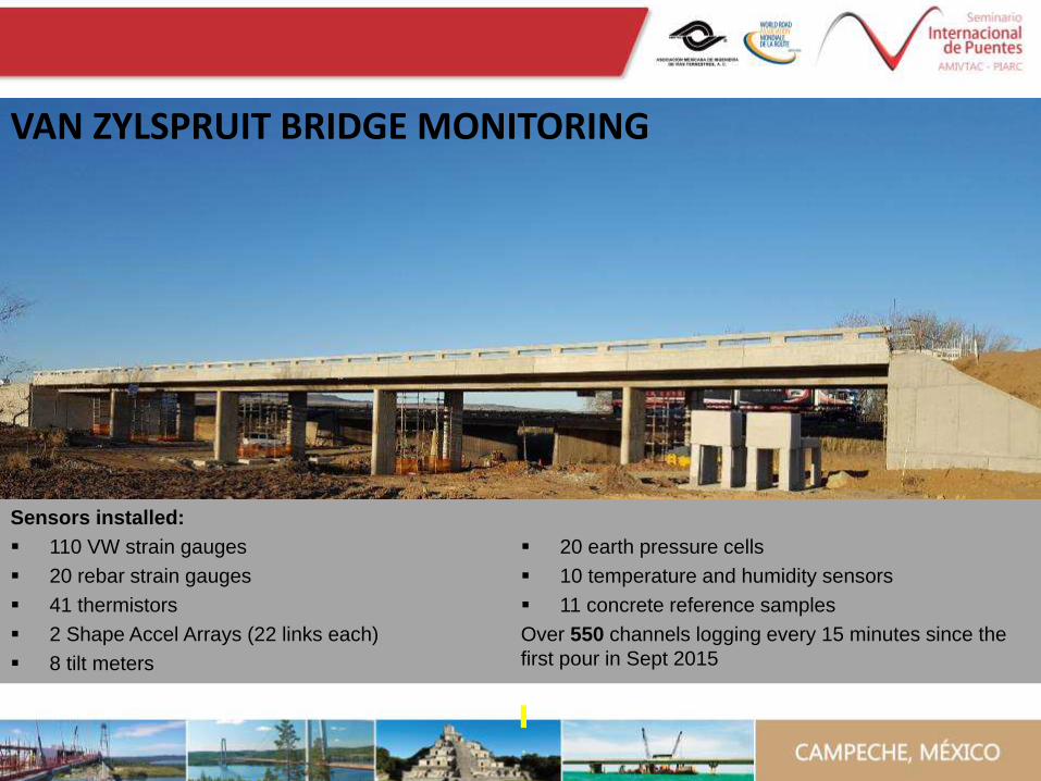
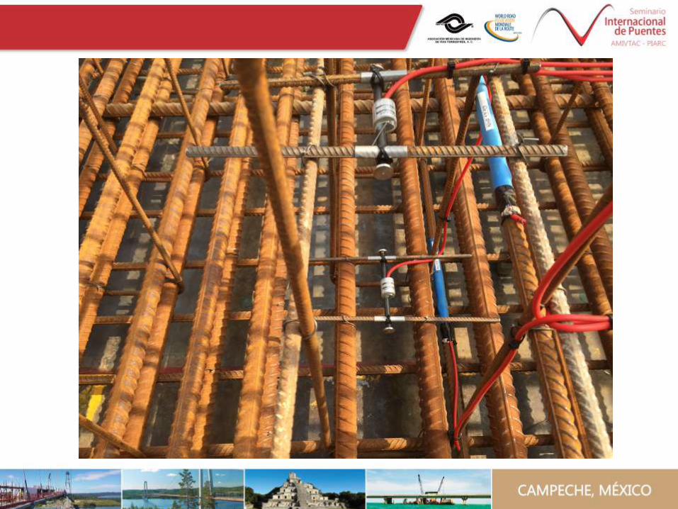
Sensors installed:
110 VW strain gauges
20 rebar strain gauges
41 thermistors
2 Shape Accel Arrays (22 links each)
8 tilt meters
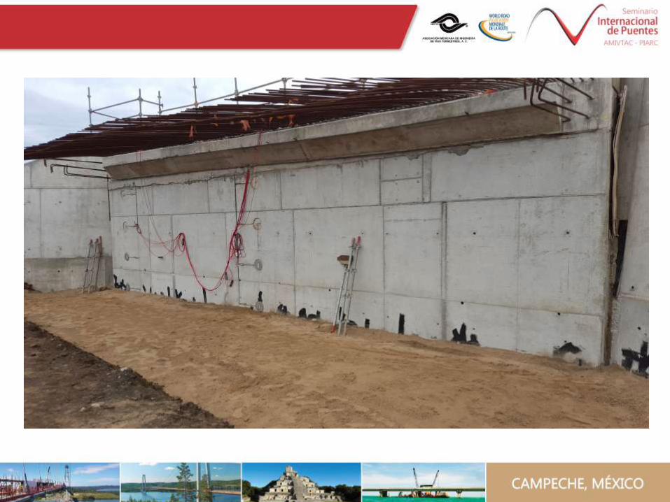
20 earth pressure cells
10 temperature and humidity sensors
11 concrete reference samples
Over 550 channels logging every 15 minutes since the
first pour in Sept 2015
.
VAN ZYLSPRUIT BRIDGE MONITORING
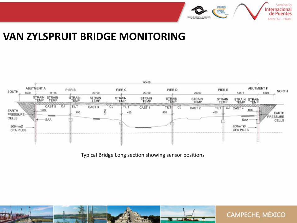
Typical Bridge Long section showing sensor positions
VAN ZYLSPRUIT BRIDGE MONITORING
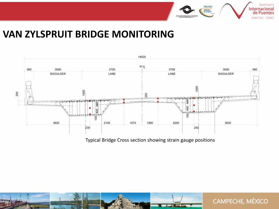
VAN ZYLSPRUIT BRIDGE MONITORING
Typical Bridge Cross section showing strain gauge positions
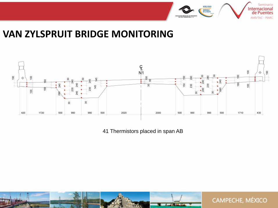
41 Thermistors placed in span AB
VAN ZYLSPRUIT BRIDGE MONITORING

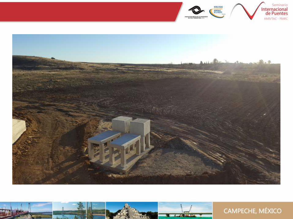

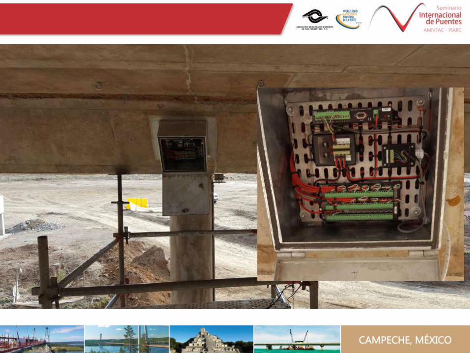

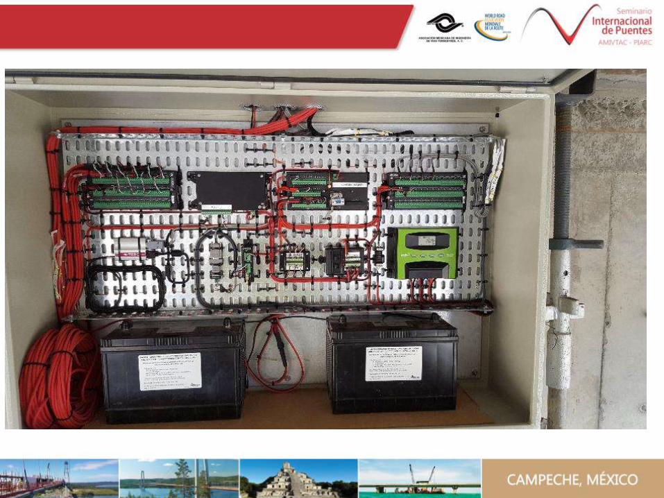
Loggers
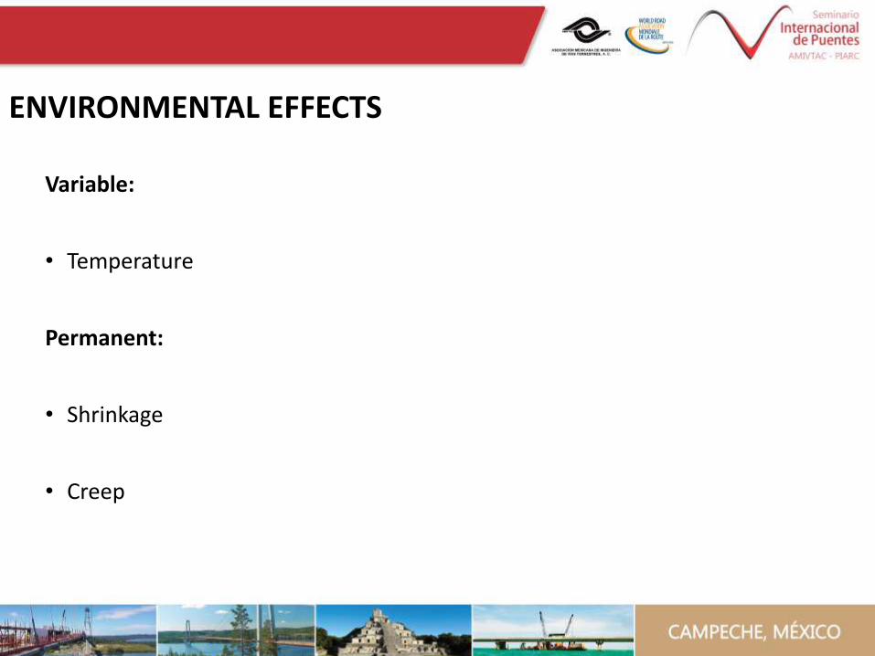
Variable:
• Temperature
Permanent:
• Shrinkage
• Creep
ENVIRONMENTAL EFFECTS
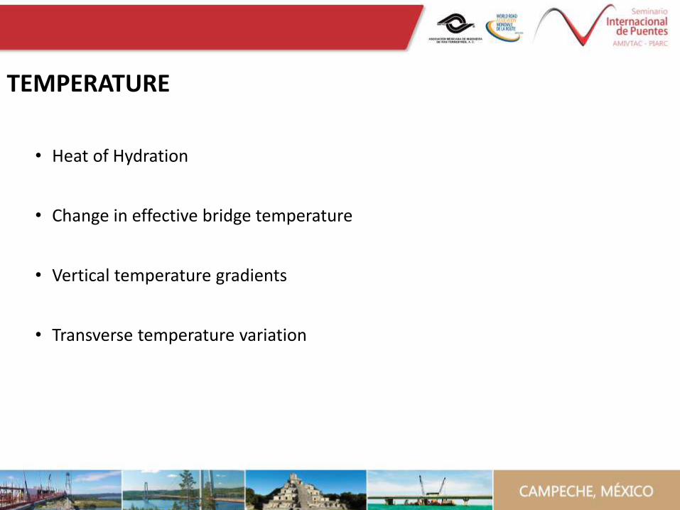
• Heat of Hydration
• Change in effective bridge temperature
• Vertical temperature gradients
• Transverse temperature variation
TEMPERATURE
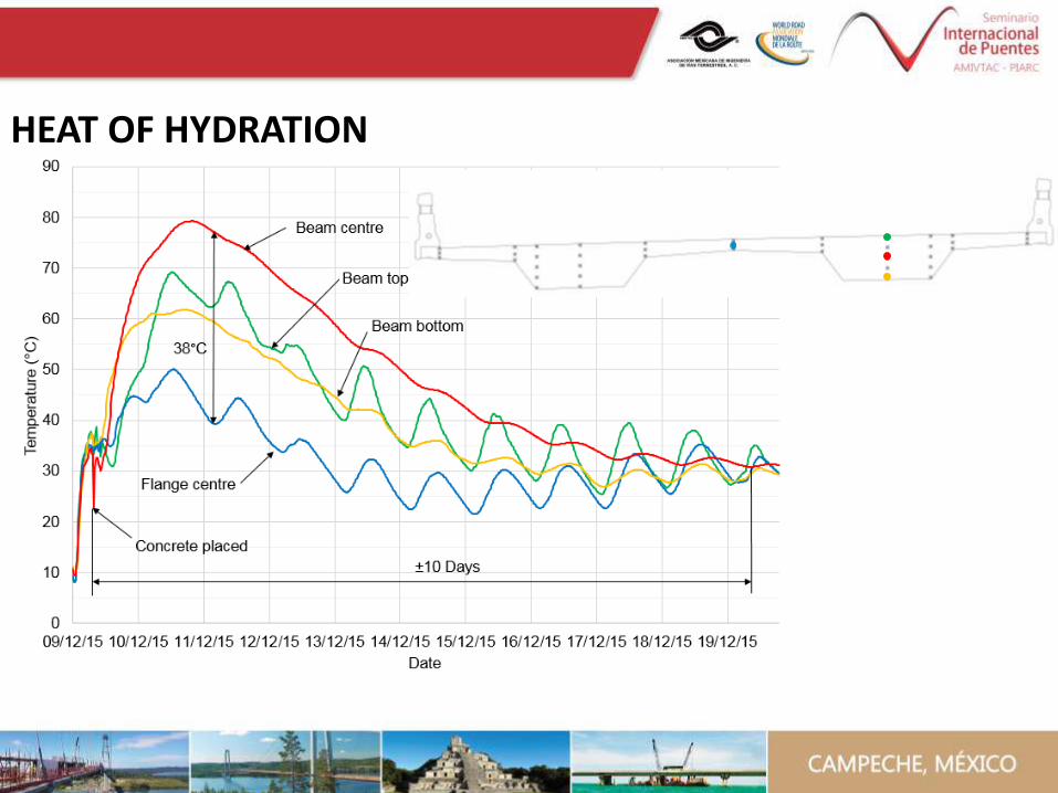
HEAT OF HYDRATION
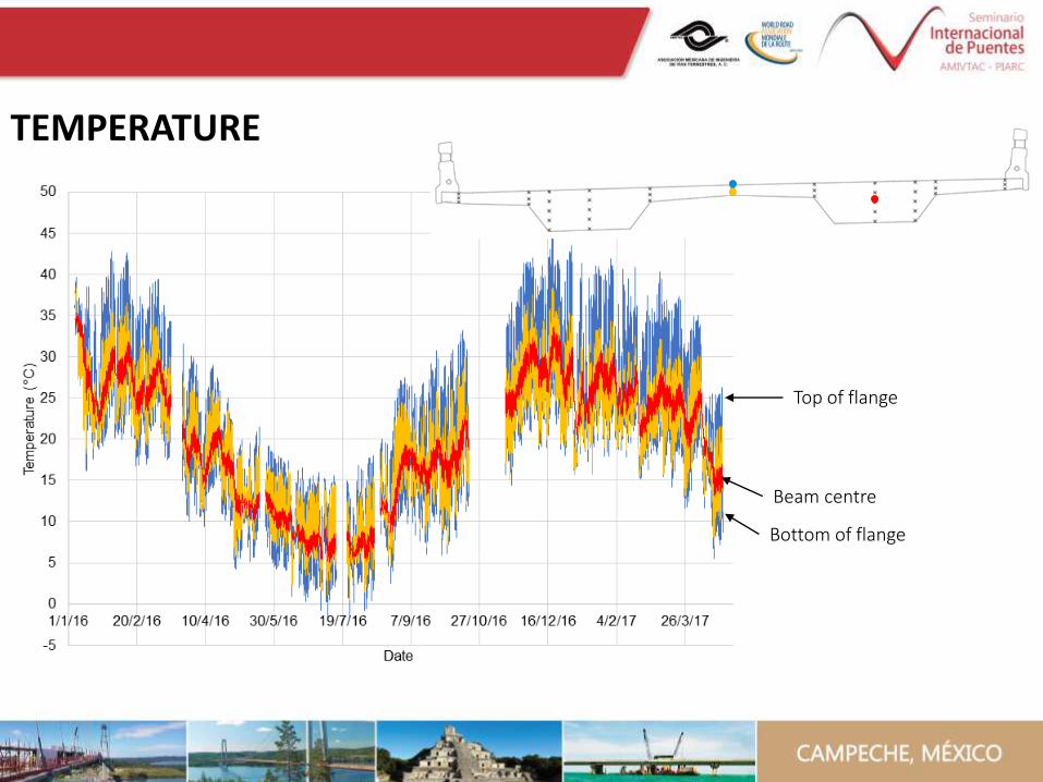
Beam centre
Top of flange
Bottom of flange
TEMPERATURE
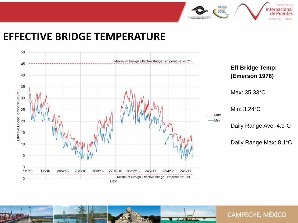
Eff Bridge Temp:
(Emerson 1976)
Max: 35.33°C
Min: 3.24°C
Daily Range Ave: 4.9°C
Daily Range Max: 8.1°C
EFFECTIVE BRIDGE TEMPERATURE
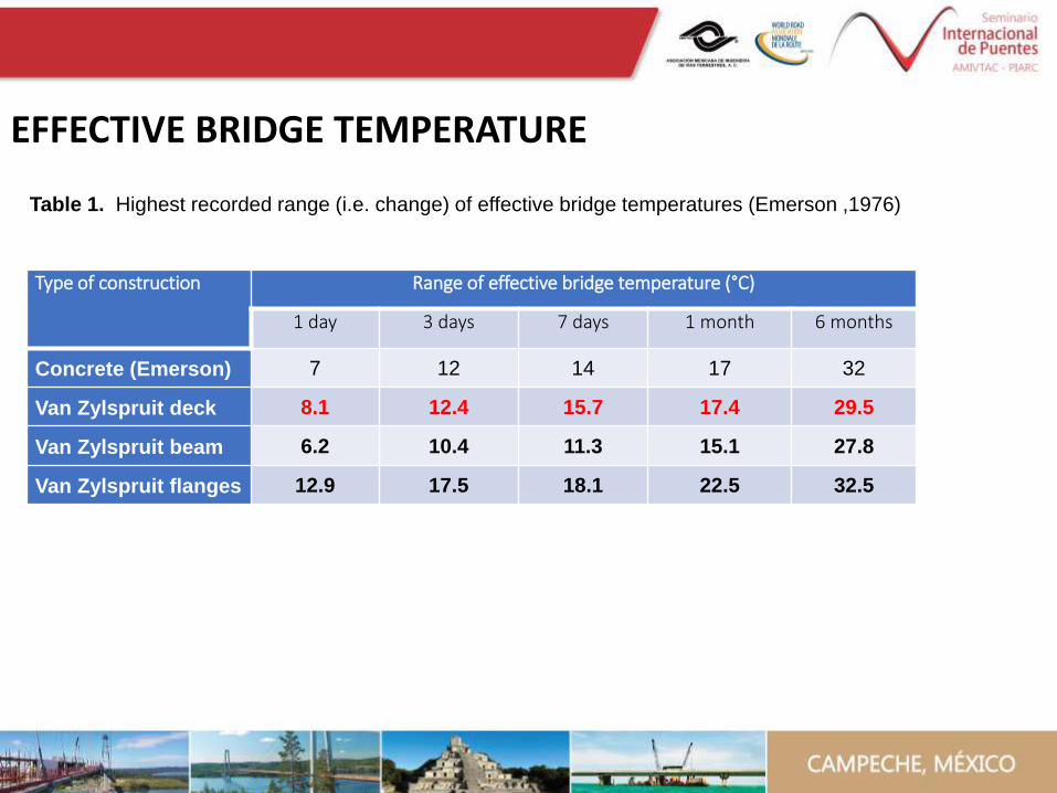
Type of construction Range of effective bridge temperature (°C)
1 day 3 days 7 days 1 month 6 months
Concrete (Emerson) 7 12 14 17 32
Van Zylspruit deck 8.1 12.4 15.7 17.4 29.5
Van Zylspruit beam 6.2 10.4 11.3 15.1 27.8
Van Zylspruit flanges 12.9 17.5 18.1 22.5 32.5
Table 1. Highest recorded range (i.e. change) of effective bridge temperatures (Emerson ,1976)
EFFECTIVE BRIDGE TEMPERATURE
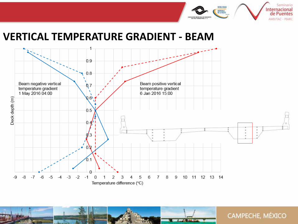
VERTICAL TEMPERATURE GRADIENT - BEAM
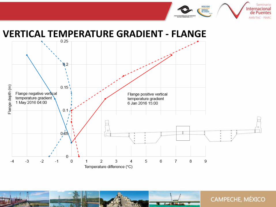
VERTICAL TEMPERATURE GRADIENT - FLANGE
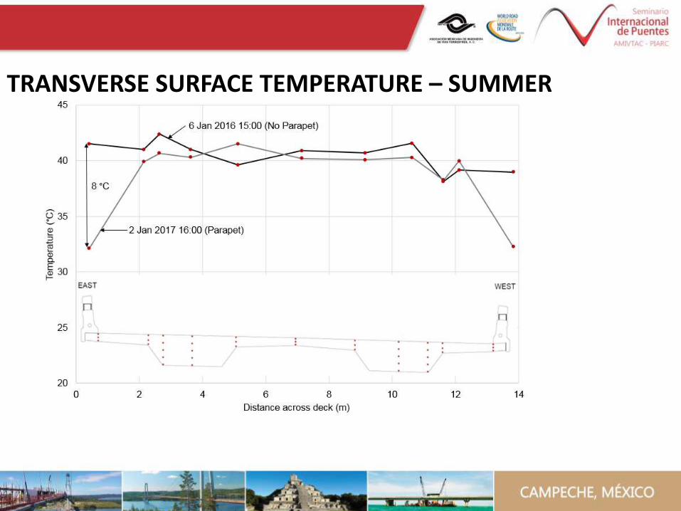
TRANSVERSE SURFACE TEMPERATURE – SUMMER
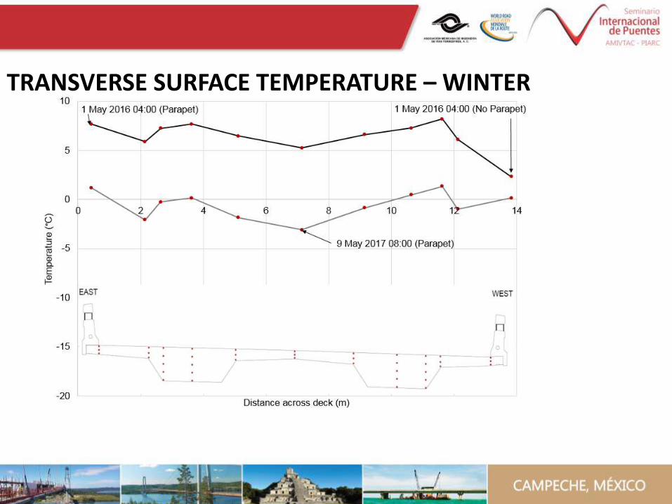
TRANSVERSE SURFACE TEMPERATURE – WINTER
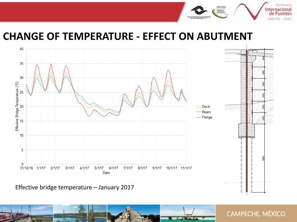
Effective bridge temperature – January 2017
CHANGE OF TEMPERATURE - EFFECT ON ABUTMENT
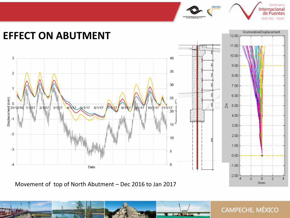
Movement of top of North Abutment – Dec 2016 to Jan 2017
EFFECT ON ABUTMENT
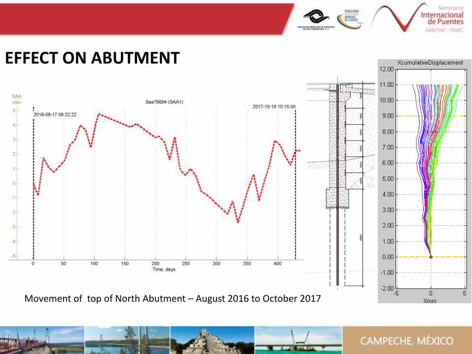
Movement of top of North Abutment – August 2016 to October 2017
EFFECT ON ABUTMENT
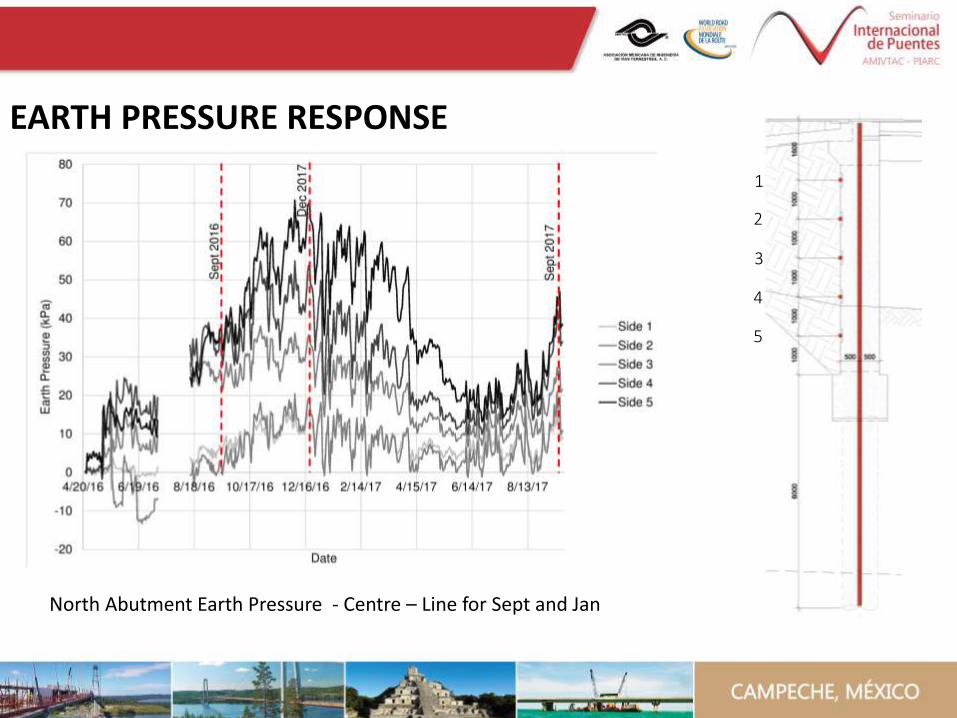
North Abutment Earth Pressure - Centre – Line for Sept and Jan
1
4
3
2
5
EARTH PRESSURE RESPONSE

Earth pressure distribution – Frame Abutment
k*= (d/0.05H)0.4 Kp
d= displacement of the top of the abutment
EARTH PRESSURE – BA 42/96
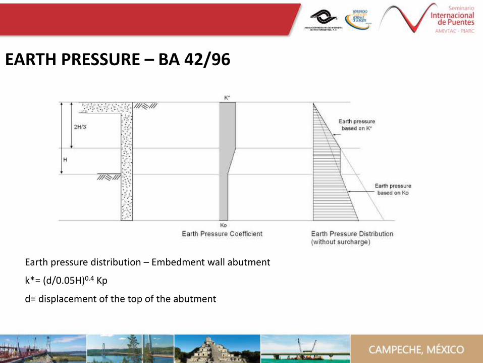
Earth pressure distribution – Embedment wall abutment
k*= (d/0.05H)0.4 Kp
d= displacement of the top of the abutment
EARTH PRESSURE – BA 42/96
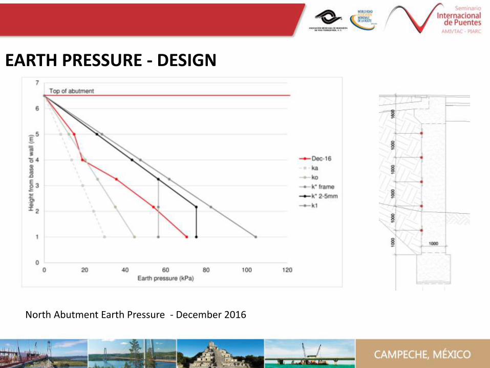
North Abutment Earth Pressure - December 2016
EARTH PRESSURE - DESIGN

Ratcheting effect
EARTH PRESSURE - RATCHETING
• Heat of hydration can’t be ignored
• Thermal movement is significantly size dependent
• Large beam dampens the thermal effects
• Earth Pressures larger than soil at rest
• Ratcheting effect observed
• Calculation of k* needs to be clarified
SUMMARY BASED ON TRENDS OBSERVED IN DATA THUS FAR

What is the effective bridge deck temperature?
Can we use Emerson’s effective bridge temperature calculations?
Response of flanges vs beams to strain?
What earth pressures must we design for?
What would the most effective deck cross section be?
Effective temperature
Shrinkage
Force on abutment
SOME OF THE DESIGN QUESTIONS TO BE ANSWERED