Embed Size (px)
Citation preview
...with people in mind
0086
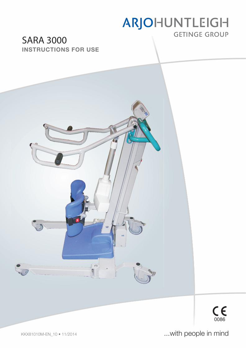
SARA 3000INSTRUCTIONS FOR USE
© ArjoHuntleigh
ArjoHuntleigh products are patented or patent pending. Patent information is available by contacting ArjoHuntleigh.
The policy of ArjoHuntleigh is one of continuous development and we therefore reserve the right to make technical alterations without notice. The content of this publication may not be copied either whole or in part without the consent of ArjoHuntleigh.
This product has been manufactured for ArjoHuntleigh by:
ArjoHuntleigh ABHans Michelsensgatan 10211 20 Malmö, Sweden
‘SARA 3000’, ArjoHuntleigh’ and ‘ARJO’ are registered trademarks of GETINGE AB.The SARA 3000 is produced in Poland by ArjoHuntleigh AB for GETINGE AB and sold underthe ArjoHuntleigh brand.
Contents
Safety Instructions . . . . . . . . . . . . . . . . . . . . . . . . . . . . . . . . . . . . . . . . 3Intended use . . . . . . . . . . . . . . . . . . . . . . . . . . . . . . . . . . . . . . . . . . . . . . . . . . 3General Safety Instructions . . . . . . . . . . . . . . . . . . . . . . . . . . . . . . . . . . . . . . . 3Symbols and Definitions used in this document . . . . . . . . . . . . . . . . . . . . . . . 4Product Lifetime . . . . . . . . . . . . . . . . . . . . . . . . . . . . . . . . . . . . . . . . . . . . . . . . 4
Foreword . . . . . . . . . . . . . . . . . . . . . . . . . . . . . . . . . . . . . . . . . . . . . . . . 5
Parts designation / legend . . . . . . . . . . . . . . . . . . . . . . . . . . . . . . . . . . 6
Product Description and Handling Instructions. . . . . . . . . . . . . . . . . 7Installation Instructions. . . . . . . . . . . . . . . . . . . . . . . . . . . . . . . . . . . . . . . . . . . 7Features and functions . . . . . . . . . . . . . . . . . . . . . . . . . . . . . . . . . . . . . . . . . . 7Control handset . . . . . . . . . . . . . . . . . . . . . . . . . . . . . . . . . . . . . . . . . . . . . . . . 7Dual control switch. . . . . . . . . . . . . . . . . . . . . . . . . . . . . . . . . . . . . . . . . . . . . . 7Emergency Stop Button . . . . . . . . . . . . . . . . . . . . . . . . . . . . . . . . . . . . . . . . . . 7Power on / Reset Button . . . . . . . . . . . . . . . . . . . . . . . . . . . . . . . . . . . . . . . . . 7Power off button. . . . . . . . . . . . . . . . . . . . . . . . . . . . . . . . . . . . . . . . . . . . . . . . 7Automatic Cut Out - for use when Raising. . . . . . . . . . . . . . . . . . . . . . . . . . . . 7Automatic Stop Function - for use when Lowering . . . . . . . . . . . . . . . . . . . . . 8System failure lower override. . . . . . . . . . . . . . . . . . . . . . . . . . . . . . . . . . . . . . 8Battery Discharge Indicator . . . . . . . . . . . . . . . . . . . . . . . . . . . . . . . . . . . . . . . 8Hour Meter . . . . . . . . . . . . . . . . . . . . . . . . . . . . . . . . . . . . . . . . . . . . . . . . . . . . 8Chassis Castor Brakes . . . . . . . . . . . . . . . . . . . . . . . . . . . . . . . . . . . . . . . . . . 8Foot Support . . . . . . . . . . . . . . . . . . . . . . . . . . . . . . . . . . . . . . . . . . . . . . . . . . 8Lower Leg Straps. . . . . . . . . . . . . . . . . . . . . . . . . . . . . . . . . . . . . . . . . . . . . . . 8Adjustable Width Chassis Legs . . . . . . . . . . . . . . . . . . . . . . . . . . . . . . . . . . . . 9Check list before use . . . . . . . . . . . . . . . . . . . . . . . . . . . . . . . . . . . . . . . . . . . . 9Preparation before transfer . . . . . . . . . . . . . . . . . . . . . . . . . . . . . . . . . . . . . . . 9Using Standing Sling or using Transfer Sling . . . . . . . . . . . . . . . . . . . . . . . . . 9
Scale. . . . . . . . . . . . . . . . . . . . . . . . . . . . . . . . . . . . . . . . . . . . . . . . . . . 13Resident scale (if fitted) . . . . . . . . . . . . . . . . . . . . . . . . . . . . . . . . . . . . . . . . . 13Verification labels/seals E.C. Units only. . . . . . . . . . . . . . . . . . . . . . . . . . . . . 13Re-verification . . . . . . . . . . . . . . . . . . . . . . . . . . . . . . . . . . . . . . . . . . . . . . . . 13Display symbols/functions . . . . . . . . . . . . . . . . . . . . . . . . . . . . . . . . . . . . . . . 14Method ‘A’ - Weighing before the resident is standing on the footrest. . . . . . 15Method ‘B’- Weighing with the resident already standing on the footrest. . . . 15Scale battery installation/change . . . . . . . . . . . . . . . . . . . . . . . . . . . . . . . . . . 16Care of your scale . . . . . . . . . . . . . . . . . . . . . . . . . . . . . . . . . . . . . . . . . . . . . 16
Battery Charging . . . . . . . . . . . . . . . . . . . . . . . . . . . . . . . . . . . . . . . . . 17
Disinfection, Cleaning and Maintenance . . . . . . . . . . . . . . . . . . . . . 19General Equipment Cleaning and Care . . . . . . . . . . . . . . . . . . . . . . . . . . . . . 19Daily checks. . . . . . . . . . . . . . . . . . . . . . . . . . . . . . . . . . . . . . . . . . . . . . . . . . 19Servicing Advice . . . . . . . . . . . . . . . . . . . . . . . . . . . . . . . . . . . . . . . . . . . . . . 19Parts lists and circuit diagrams . . . . . . . . . . . . . . . . . . . . . . . . . . . . . . . . . . . 20Periodic Testing . . . . . . . . . . . . . . . . . . . . . . . . . . . . . . . . . . . . . . . . . . . . . . . 20Environmental Advice . . . . . . . . . . . . . . . . . . . . . . . . . . . . . . . . . . . . . . . . . . 20
1
Slings . . . . . . . . . . . . . . . . . . . . . . . . . . . . . . . . . . . . . . . . . . . . . . . . . . . . . . . 20
Care and Preventive Maintenance. . . . . . . . . . . . . . . . . . . . . . . . . . . 21Preventive Maintenance Schedule . . . . . . . . . . . . . . . . . . . . . . . . . . . . . . . . 21
Labels. . . . . . . . . . . . . . . . . . . . . . . . . . . . . . . . . . . . . . . . . . . . . . . . . . 22
Technical Specification . . . . . . . . . . . . . . . . . . . . . . . . . . . . . . . . . . . 23Component Weights . . . . . . . . . . . . . . . . . . . . . . . . . . . . . . . . . . . . . . . . . . . 23Electrical . . . . . . . . . . . . . . . . . . . . . . . . . . . . . . . . . . . . . . . . . . . . . . . . . . . . 23Environment. . . . . . . . . . . . . . . . . . . . . . . . . . . . . . . . . . . . . . . . . . . . . . . . . . 24Maximum sound power level . . . . . . . . . . . . . . . . . . . . . . . . . . . . . . . . . . . . . 24Scale . . . . . . . . . . . . . . . . . . . . . . . . . . . . . . . . . . . . . . . . . . . . . . . . . . . . . . . 24Abb.Dimensions. . . . . . . . . . . . . . . . . . . . . . . . . . . . . . . . . . . . . . . . . . . . . . . 25
Problem Solving / Troubleshooting Guide . . . . . . . . . . . . . . . . . . . . 26
Electromagnetic Compatibility (EMC) . . . . . . . . . . . . . . . . . . . . . . . . 27
2
Safety Instructions
Intended use
SARA 3000 is a mobile raising aid, with a Safe Working Load of 200 kg (440 lbs), intended to be used on a horizontal surface for raising to a standing position and short transfer of residents (e.g. raising from bed and transit to wheelchair, or from wheelchair to toilet) in hospitals, nursing homes or other health care facilities where the resident has been clinically assessed to correspond to the following categories;
Category C- Sits in a wheelchair- Is able to partially bear weight on at least one leg.- Has some trunk stability- Dependent on carer in most situations- Physically demanding for carer.- Stimulation of remaining abilities is important.
SARA 3000 shall always be handled by a trained caregiver, continuously attending to the resident, and in accordance with the instructions outlined in these Operating and Product Care Instructions.
SARA 3000 is intended to be used with clip slings only -except for the ‘Transfer Slings’ which also have loops for attachment of the leg flaps to the central lug situated on the resident support arms.Use slings that are designed for SARA 3000.
General Safety Instructions
Any references made to the ‘resident’ or ‘patient’ in this document, means the person being raised.
These Instructions for use are mandatory for the safe and effective handling of SARA 3000, including the safety of the resident and the caregiver.
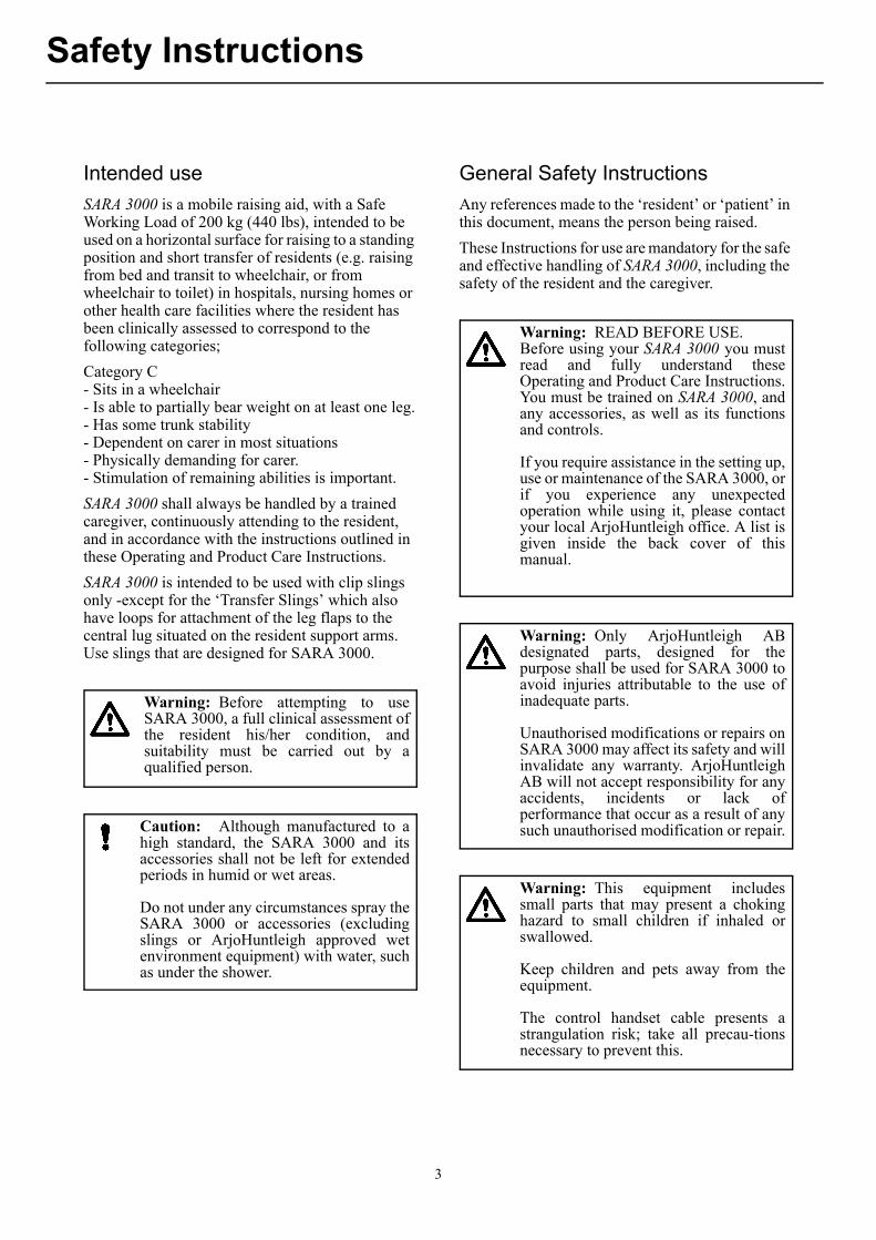
Warning: Before attempting to useSARA 3000, a full clinical assessment ofthe resident his/her condition, andsuitability must be carried out by aqualified person.
Caution: Although manufactured to ahigh standard, the SARA 3000 and itsaccessories shall not be left for extendedperiods in humid or wet areas.
Do not under any circumstances spray theSARA 3000 or accessories (excludingslings or ArjoHuntleigh approved wetenvironment equipment) with water, suchas under the shower.
Warning: READ BEFORE USE.Before using your SARA 3000 you mustread and fully understand theseOperating and Product Care Instructions.You must be trained on SARA 3000, andany accessories, as well as its functionsand controls.
If you require assistance in the setting up,use or maintenance of the SARA 3000, orif you experience any unexpectedoperation while using it, please contactyour local ArjoHuntleigh office. A list isgiven inside the back cover of thismanual.
Warning: Only ArjoHuntleigh ABdesignated parts, designed for thepurpose shall be used for SARA 3000 toavoid injuries attributable to the use ofinadequate parts.
Unauthorised modifications or repairs onSARA 3000 may affect its safety and willinvalidate any warranty. ArjoHuntleighAB will not accept responsibility for anyaccidents, incidents or lack ofperformance that occur as a result of anysuch unauthorised modification or repair.
Warning: This equipment includessmall parts that may present a chokinghazard to small children if inhaled orswallowed.
Keep children and pets away from theequipment.
The control handset cable presents astrangulation risk; take all precau-tionsnecessary to prevent this.
3
Safety Instructions
Symbols and Definitions used in this document
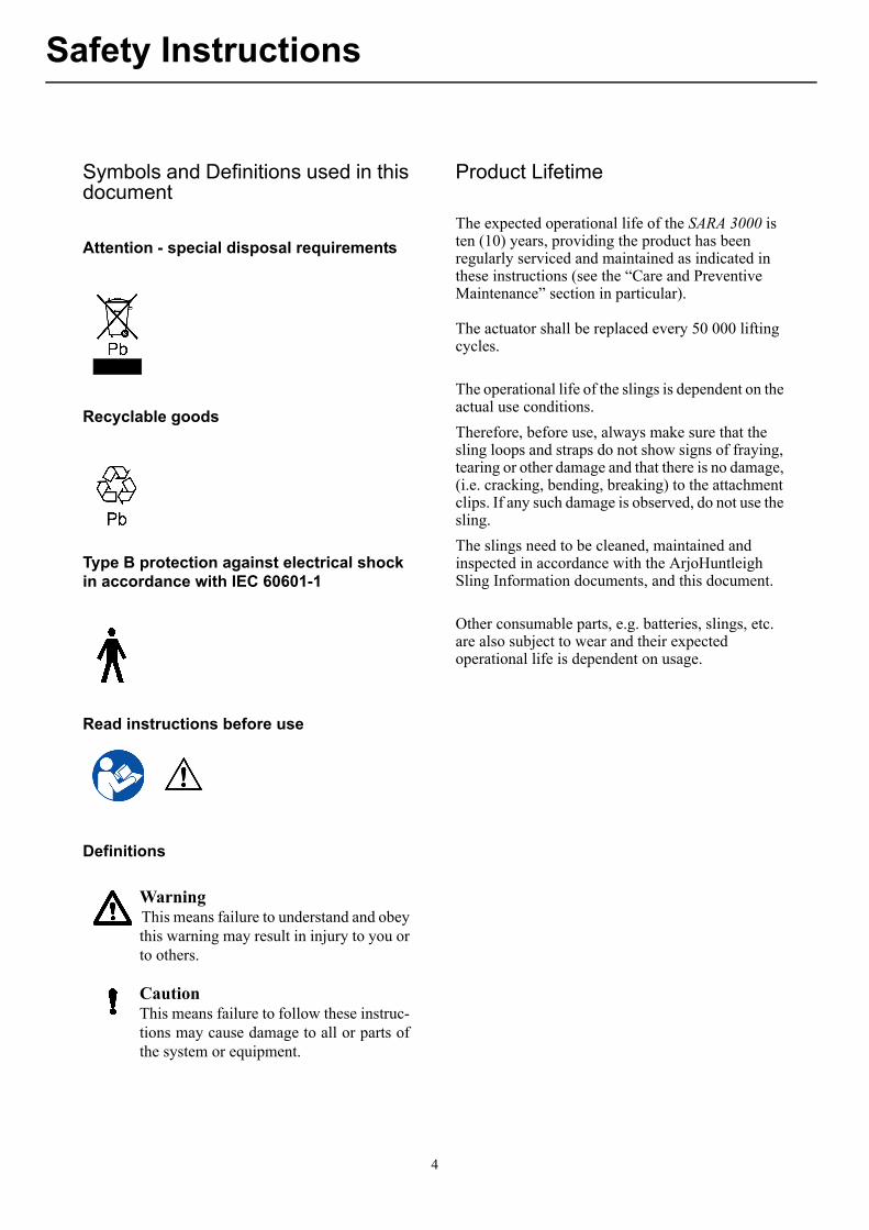
Attention - special disposal requirements
Recyclable goods
Type B protection against electrical shock in accordance with IEC 60601-1
Read instructions before use
Definitions
Product Lifetime
The expected operational life of the SARA 3000 is ten (10) years, providing the product has been regularly serviced and maintained as indicated in these instructions (see the “Care and Preventive Maintenance” section in particular).
The actuator shall be replaced every 50 000 lifting cycles.
The operational life of the slings is dependent on the actual use conditions.
Therefore, before use, always make sure that the sling loops and straps do not show signs of fraying, tearing or other damage and that there is no damage, (i.e. cracking, bending, breaking) to the attachment clips. If any such damage is observed, do not use the sling.
The slings need to be cleaned, maintained and inspected in accordance with the ArjoHuntleigh Sling Information documents, and this document.
Other consumable parts, e.g. batteries, slings, etc. are also subject to wear and their expected operational life is dependent on usage.
WarningThis means failure to understand and obeythis warning may result in injury to you orto others.
CautionThis means failure to follow these instruc-tions may cause damage to all or parts ofthe system or equipment.
4
Foreword
Thank you for using SARA 3000.
If you would require information, further to these Operating and Product Care Instructions, or replacement parts, please contact your local ArjoHuntleigh representative who can provide comprehensive support and service programs to maximize the long-term safety, reliability and value of your SARA 3000.
If there is anything in these Operating and Product Care Instructions that is confusing or difficult to understand, please contact your local ArjoHuntleigh representative.
Contact details appear on the back cover of this document.
Should any other information (e.g. a video or abbreviated Guidelines For Use) accompany these Operating and Product Care Instructions, please note that they do not replace the information in this booklet as the latter also contains important safety instructions. Any abridged guidelines are not a replacement of the full instructions for SARA 3000, its parts and ArjoHuntleigh sling. Before operating SARA 3000 be sure that you read, understand and follow all the instructions and guidelines for both SARA 3000 and the ArjoHuntleigh sling.
5
Parts designation / legend
Parts referred to in this manual
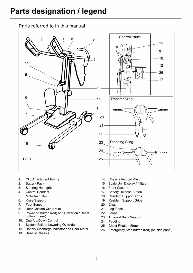
1. Clip Attachment Points2. Battery Pack3. Steering Handgrips4. Control Handset5. Motor/Actuator6. Knee Support7. Foot Support8. Rear Castors with Brake9. Power off button (red) and Power on / Reset
button (green)10. Dual Up/Down Control11. System Failure Lowering Override12. Battery Discharge Indicator and Hour Meter 13. Base of Chassis
14. Chassis Vertical Mast15. Scale Unit Display (if fitted)16. Front Castors17. Battery Release Button18. Resident Support Arms19. Resident Support Grips20. Clips21. Leg Flaps22. Loops23. Anti-skid Back Support24. Padding25. Chest Fixation Strap26. Emergency Stop button (red) (on side panel)
Fig. 1
Control Panel
Transfer Sling
Standing Sling
1
2
3
4
5
6
7
8
9
1011
12
13
14
15
16
17
18 19
20
21
22
23
24
25
26
6
Product Description and Handling Instructions
Installation Instructions.
The SARA 3000 is delivered to you in fully assembled state.
Unpack the battery pack supplied, and fully charge it for a minimum of 24 hours, see “Battery Charging” section.
When the battery pack is fully charged, disconnect the electric power, remove the pack from the charger, and insert it fully back into the SARA 3000 battery compartment located at the rear of the mast.
Features and functions
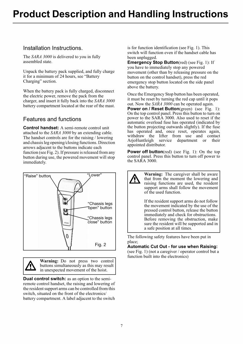
Control handset: A semi-remote control unit attached to the SARA 3000 by an extending cable. The handset controls are for the raising / lowering and chassis leg opening/closing functions. Direction arrows adjacent to the buttons indicate each function (see Fig. 2). If pressure is released from any button during use, the powered movement will stop immediately.
Dual control switch: as an option to the semi-remote control handset, the raising and lowering of the resident support arms can be controlled from this switch, situated on the front of the electronics/battery compartment. A label adjacent to the switch
is for function identification (see Fig. 1). This switch will function even if the handset cable has been unplugged.Emergency Stop Button(red) (see Fig. 1): If you have to immediately stop any powered movement (other than by releasing pressure on the button on the control handset), press the red emergency stop button located on the side panel above the battery.
Once the Emergency Stop button has been operated, it must be reset by turning the red cap until it pops out. Now the SARA 3000 can be operated again.Power on / Reset Button(green) (see Fig. 1):On the top control panel. Press this button to turn onpower to the SARA 3000. Also used to reset if theautomatic overload fuse has operated (indicated bythe button projecting outwards slightly). If the fusehas operated and, once reset, operates again,withdraw the lifter from use and contactArjoHuntleigh service department or theirappointed distributor.
Power off button(red) (see Fig. 1): On the topcontrol panel. Press this button to turn off power tothe SARA 3000.
The following safety features have been put in place;Automatic Cut Out - for use when Raising: (see Fig. 1) (not a caregiver / operator control but a function built into the electronics)
“Raise” button “Lower”
“Chassis legs open” button
“Chassis legs close” button
Fig. 2
Warning: Do not press two controlbuttons simultaneously as this may resultin unexpected movement of the hoist.
Warning: The caregiver shall be awarethat from the moment the lowering andraising functions are used, the residentsupport arms shall follow the movementof the used function.
If the resident support arms do not followthe movement indicated by the use of thepressed control button, release the buttonimmediately and check for obstructions.Before removing the obstruction, makesure the resident will be supported and ina safe position at all times.
7
Product Description and Handling Instructions
If the equipment is inadvertently overloaded (trying to raise a resident heavier than permitted), an automatic ‘cut out’ operates to prevent the SARA 3000 lifting a load in excess of the safe working load; this will stop the lift motion automatically. If this automatic cut out occurs, the electronics will reset when the button on the handset is released. After this, the resident can be lowered, by pressing the “lower” function button on the handset. Remove the resident from the equipment.
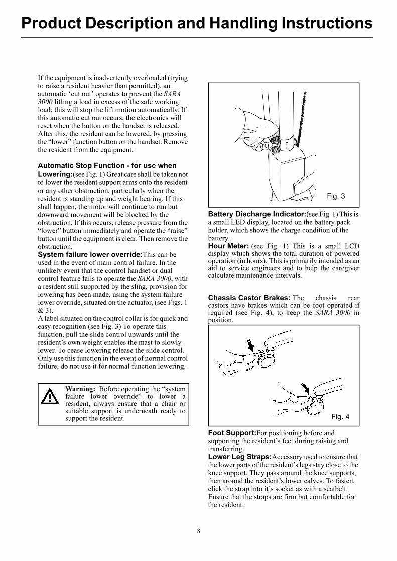
Automatic Stop Function - for use when Lowering:(see Fig. 1) Great care shall be taken not to lower the resident support arms onto the resident or any other obstruction, particularly when the resident is standing up and weight bearing. If this shall happen, the motor will continue to run but downward movement will be blocked by the obstruction. If this occurs, release pressure from the “lower” button immediately and operate the “raise” button until the equipment is clear. Then remove the obstruction.System failure lower override:This can be used in the event of main control failure. In the unlikely event that the control handset or dual control feature fails to operate the SARA 3000, with a resident still supported by the sling, provision for lowering has been made, using the system failure lower override, situated on the actuator, (see Figs. 1 & 3). A label situated on the control collar is for quick and easy recognition (see Fig. 3) To operate this function, pull the slide control upwards until the resident’s own weight enables the mast to slowly lower. To cease lowering release the slide control. Only use this function in the event of normal control failure, do not use it for normal function lowering.
Battery Discharge Indicator:(see Fig. 1) This is a small LED display, located on the battery pack holder, which shows the charge condition of the battery.Hour Meter: (see Fig. 1) This is a small LCDdisplay which shows the total duration of poweredoperation (in hours). This is primarily intended as anaid to service engineers and to help the caregivercalculate maintenance intervals.
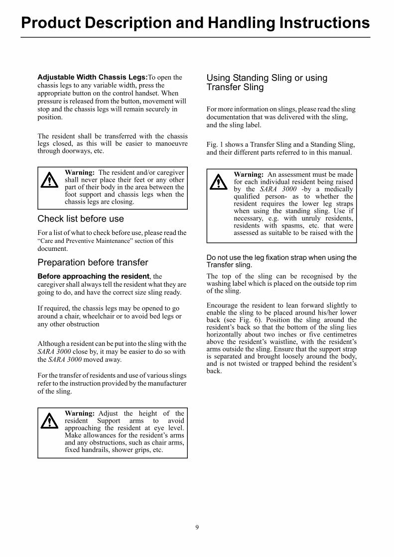
Chassis Castor Brakes: The chassis rearcastors have brakes which can be foot operated ifrequired (see Fig. 4), to keep the SARA 3000 inposition.
Foot Support:For positioning before and supporting the resident’s feet during raising and transferring.Lower Leg Straps:Accessory used to ensure that the lower parts of the resident’s legs stay close to the knee support. They pass around the knee supports, then around the resident’s lower calves. To fasten, click the strap into it’s socket as with a seatbelt. Ensure that the straps are firm but comfortable for the resident.
Warning: Before operating the “systemfailure lower override” to lower aresident, always ensure that a chair orsuitable support is underneath ready tosupport the resident.
Fig. 3
Fig. 4
8
Product Description and Handling Instructions
Adjustable Width Chassis Legs:To open the chassis legs to any variable width, press the appropriate button on the control handset. When pressure is released from the button, movement will stop and the chassis legs will remain securely in position.
The resident shall be transferred with the chassislegs closed, as this will be easier to manoeuvrethrough doorways, etc.
Check list before use
For a list of what to check before use, please read the “Care and Preventive Maintenance” section of this document.
Preparation before transfer
Before approaching the resident, the caregiver shall always tell the resident what they are going to do, and have the correct size sling ready.
If required, the chassis legs may be opened to go around a chair, wheelchair or to avoid bed legs or any other obstruction
Although a resident can be put into the sling with the SARA 3000 close by, it may be easier to do so with the SARA 3000 moved away.
For the transfer of residents and use of various slings refer to the instruction provided by the manufacturer of the sling.
Using Standing Sling or using Transfer Sling
For more information on slings, please read the sling documentation that was delivered with the sling, and the sling label.
Fig. 1 shows a Transfer Sling and a Standing Sling, and their different parts referred to in this manual.
Do not use the leg fixation strap when using theTransfer sling.
The top of the sling can be recognised by thewashing label which is placed on the outside top rimof the sling.
Encourage the resident to lean forward slightly toenable the sling to be placed around his/her lowerback (see Fig. 6). Position the sling around theresident’s back so that the bottom of the sling lieshorizontally about two inches or five centimetresabove the resident’s waistline, with the resident’sarms outside the sling. Ensure that the support strapis separated and brought loosely around the body,and is not twisted or trapped behind the resident’sback.
Warning: The resident and/or caregivershall never place their feet or any otherpart of their body in the area between thefoot support and chassis legs when thechassis legs are closing.
Warning: Adjust the height of theresident Support arms to avoidapproaching the resident at eye level.Make allowances for the resident’s armsand any obstructions, such as chair arms,fixed handrails, shower grips, etc.
Warning: An assessment must be madefor each individual resident being raisedby the SARA 3000 -by a medicallyqualified person- as to whether theresident requires the lower leg strapswhen using the standing sling. Use ifnecessary, e.g. with unruly residents,residents with spasms, etc. that wereassessed as suitable to be raised with the
9
Product Description and Handling Instructions
When applying the transfer sling, take each leg section of the sling in turn and slide under each leg, (see Fig. 5).
To fasten the support strap securely, press thebuckles (if available) or velcro (if available)together. The strap shall be tight, but comfortablefor the resident. See fig 9. Remember to tighten thestrap once the resident becomes raised from thechair.
The sling may be applied before or after the SARA 3000 is brought into position.
The sling support strap will help to support the resident in the sling during the raising procedure. The strap also retains the sling in the correct position around the resident.
If the SARA 3000 is not already close to the resident, bring it to the resident.
Apply the clips to the attachment points, and secure them for safety by pulling the clips as shown in Fig. 7.
When using the transfer sling; identify the attachment loop on each leg-side -left and right- of the sling and attach them on the central lug located in between the resident support arms, positioned towards the resident. (see Fig 8)
Fig. 5
Fig. 6
Warning: The sling chest support strapmust always be applied and fastenedwhen using the sling.
Fig. 7
Fig. 8
10
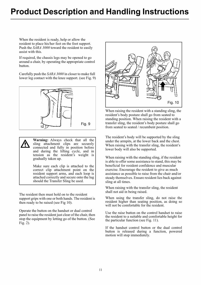
Product Description and Handling Instructions
When the resident is ready, help or allow the resident to place his/her feet on the foot support. Push the SARA 3000 toward the resident to easily assist with this.
If required, the chassis legs may be opened to go around a chair, by operating the appropriate control button.
Carefully push the SARA 3000 in closer to make full lower leg contact with the knee support. (see Fig. 9)
The resident then must hold on to the resident support grips with one or both hands. The resident is then ready to be raised (see Fig 10).
Operate the button on the handset or dual control panel to raise the resident just clear of the chair, then stop the equipment by letting go of the button. (See Fig. 2).
When raising the resident with a standing sling, the resident’s body posture shall go from seated to standing position. When raising the resident with a transfer sling, the resident’s body posture shall go from seated to seated / recumbent position.
The resident’s body will be supported by the sling under the armpits, at the lower back and the chest. When raising with the transfer sling, the resident’s lower body will also be supported.
When raising with the standing sling, if the resident is able to offer some assistance to stand, this may be beneficial for resident confidence and muscular exercise. Encourage the resident to give as much assistance as possible to raise from the chair and/or steady themselves. Ensure resident lies back against sling at all times.
When raising with the transfer sling, the resident shall not aid in being raised.
When using the transfer sling, do not raise theresident higher than seating position, as doing sowill not be comfortable for the resident.
Use the raise button on the control handset to raisethe resident to a suitable and comfortable height forthe particular function (see Fig. 11).
If the handset control button or the dual controlbutton is released during a function, poweredmotion will stop immediately.
Fig. 9
Warning: Always check that all thesling attachment clips are securelyconnected and fully in position beforeand during the lifting cycle, and intension as the resident’s weight isgradually taken up.
Make sure each clip is attached to thecorrect clip attachment point on theresident support arms, and each loop isattached correctly and secure onto the lugshould the Transfer Sling be used.
Fig. 10
11
Product Description and Handling Instructions
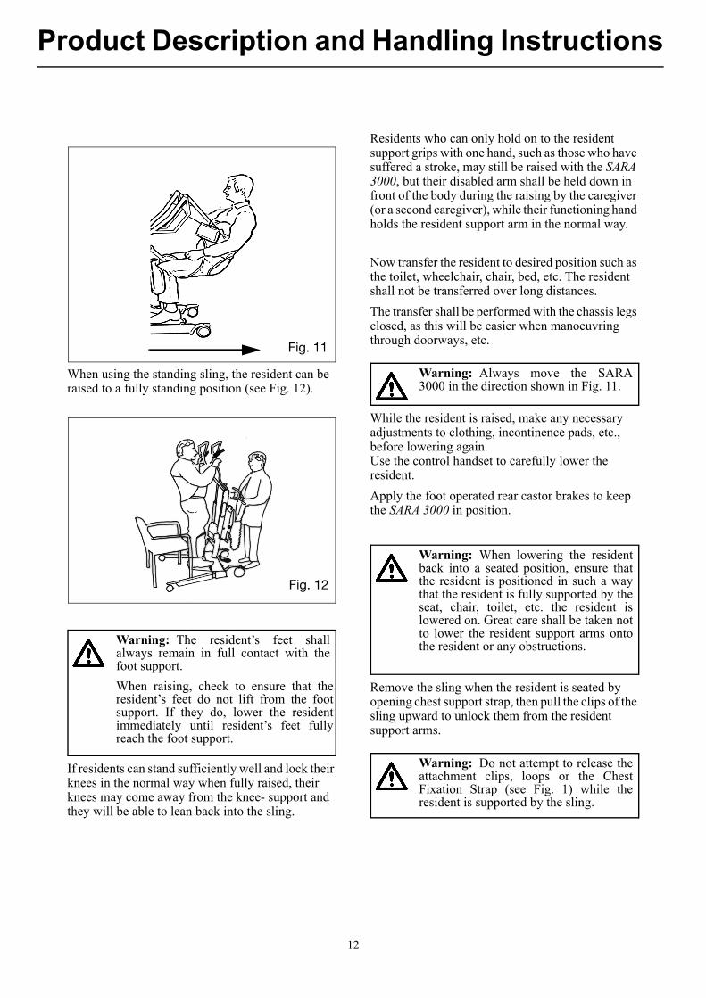
When using the standing sling, the resident can be raised to a fully standing position (see Fig. 12).
If residents can stand sufficiently well and lock their knees in the normal way when fully raised, their knees may come away from the knee- support and they will be able to lean back into the sling.
Residents who can only hold on to the resident support grips with one hand, such as those who have suffered a stroke, may still be raised with the SARA 3000, but their disabled arm shall be held down in front of the body during the raising by the caregiver (or a second caregiver), while their functioning hand holds the resident support arm in the normal way.
Now transfer the resident to desired position such as the toilet, wheelchair, chair, bed, etc. The resident shall not be transferred over long distances.
The transfer shall be performed with the chassis legs closed, as this will be easier when manoeuvring through doorways, etc.
While the resident is raised, make any necessary adjustments to clothing, incontinence pads, etc., before lowering again. Use the control handset to carefully lower the resident.
Apply the foot operated rear castor brakes to keep the SARA 3000 in position.
Remove the sling when the resident is seated by opening chest support strap, then pull the clips of the sling upward to unlock them from the resident support arms.
Fig. 11
Fig. 12
Warning: The resident’s feet shallalways remain in full contact with thefoot support.
When raising, check to ensure that theresident’s feet do not lift from the footsupport. If they do, lower the residentimmediately until resident’s feet fullyreach the foot support.
Warning: Always move the SARA3000 in the direction shown in Fig. 11.
Warning: When lowering the residentback into a seated position, ensure thatthe resident is positioned in such a waythat the resident is fully supported by theseat, chair, toilet, etc. the resident islowered on. Great care shall be taken notto lower the resident support arms ontothe resident or any obstructions.
Warning: Do not attempt to release theattachment clips, loops or the ChestFixation Strap (see Fig. 1) while theresident is supported by the sling.
12
Scale
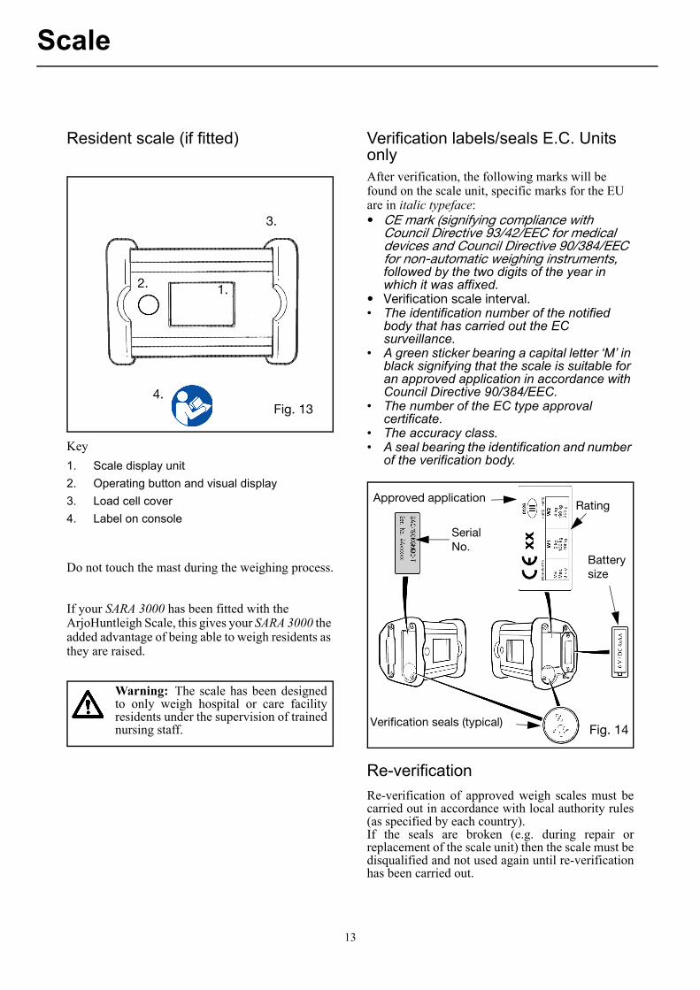
Resident scale (if fitted)
Key
1. Scale display unit
2. Operating button and visual display
3. Load cell cover
4. Label on console
Do not touch the mast during the weighing process.
If your SARA 3000 has been fitted with the ArjoHuntleigh Scale, this gives your SARA 3000 the added advantage of being able to weigh residents as they are raised.
Verification labels/seals E.C. Units onlyAfter verification, the following marks will be found on the scale unit, specific marks for the EU are in italic typeface: • CE mark (signifying compliance with
Council Directive 93/42/EEC for medical devices and Council Directive 90/384/EEC for non-automatic weighing instruments, followed by the two digits of the year in which it was affixed.
• Verification scale interval.• The identification number of the notified
body that has carried out the EC surveillance.
• A green sticker bearing a capital letter ‘M’ in black signifying that the scale is suitable for an approved application in accordance with Council Directive 90/384/EEC.
• The number of the EC type approval certificate.
• The accuracy class.• A seal bearing the identification and number
of the verification body.
Re-verification
Re-verification of approved weigh scales must becarried out in accordance with local authority rules(as specified by each country). If the seals are broken (e.g. during repair orreplacement of the scale unit) then the scale must bedisqualified and not used again until re-verificationhas been carried out.
1.2.
3.
4.Fig. 13
Warning: The scale has been designedto only weigh hospital or care facilityresidents under the supervision of trainednursing staff.
Approved application
SerialNo.
Verification seals (typical)
Batterysize
Rating
Fig. 14
13
Scale
Display symbols/functions
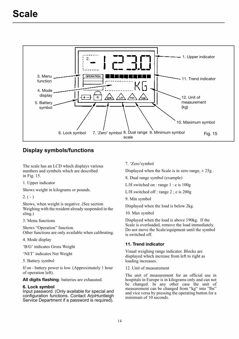
The scale has an LCD which displays various numbers and symbols which are described in Fig. 15.
1. Upper indicator
Shows weight in kilograms or pounds.
2. ( - )
Shows, when weight is negative. (See section Weighing with the resident already suspended in the sling.)
3. Menu functions
Shows “Operation” function.Other functions are only available when calibrating.
4. Mode display
‘B/G’ indicates Gross Weight
‘NET’ indicates Net Weight
5. Battery symbol
If on - battery power is low. (Approximately 1 hour of operation left).
All digits flashing- batteries are exhausted.
6. Lock symbolInput password. (Only available for special andconfiguration functions. Contact ArjoHuntleighService Department if a password is required).
7. ‘Zero’symbol
Displayed when the Scale is in zero range, ± 25g .
8. Dual range symbol (example)
L/H switched on : range 1 : e is 100g
L/H switched off : range 2 ; e is 200g
9. Min symbol
Displayed when the load is below 2kg.
10. Max symbol
Displayed when the load is above 190kg. If the Scale is overloaded, remove the load immediately. Do not move the Scale/equipment until the symbol is switched off.
11. Trend indicator
Visual weighing range indicator. Blocks are displayed which increase from left to right as loading increases.
12. Unit of measurement
The unit of measurement for an official use inhospitals in Europe is in kilograms only and can notbe changed. In any other case the unit ofmeasurement can be changed from “kg“ into ”lbs”and vice versa by pressing the operating button for aminimum of 10 seconds.
3. Menufunction
4. Modedisplay
5. Batterysymbol
1. Upper indicator
11. Trend indicator
12. Unit of measurement(kg)
10. Maximum symbol
9. Minimum symbol8. Dual range scale
7. ‘Zero’ symbol6. Lock symbol Fig. 15
2.
14
Scale
There are two methods to weigh the resident:
Method ‘A’ - Weighing before the resident is standing on the footrest.
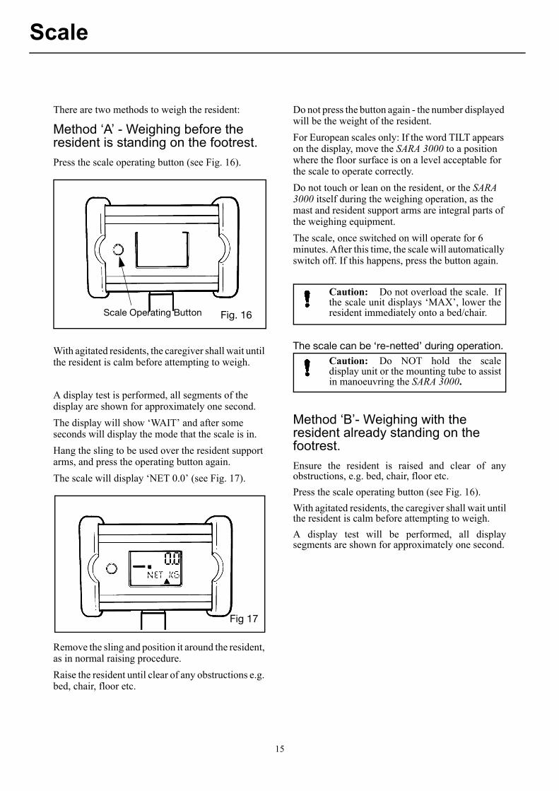
Press the scale operating button (see Fig. 16).
With agitated residents, the caregiver shall wait until the resident is calm before attempting to weigh.
A display test is performed, all segments of the display are shown for approximately one second.
The display will show ‘WAIT’ and after some seconds will display the mode that the scale is in.
Hang the sling to be used over the resident support arms, and press the operating button again.
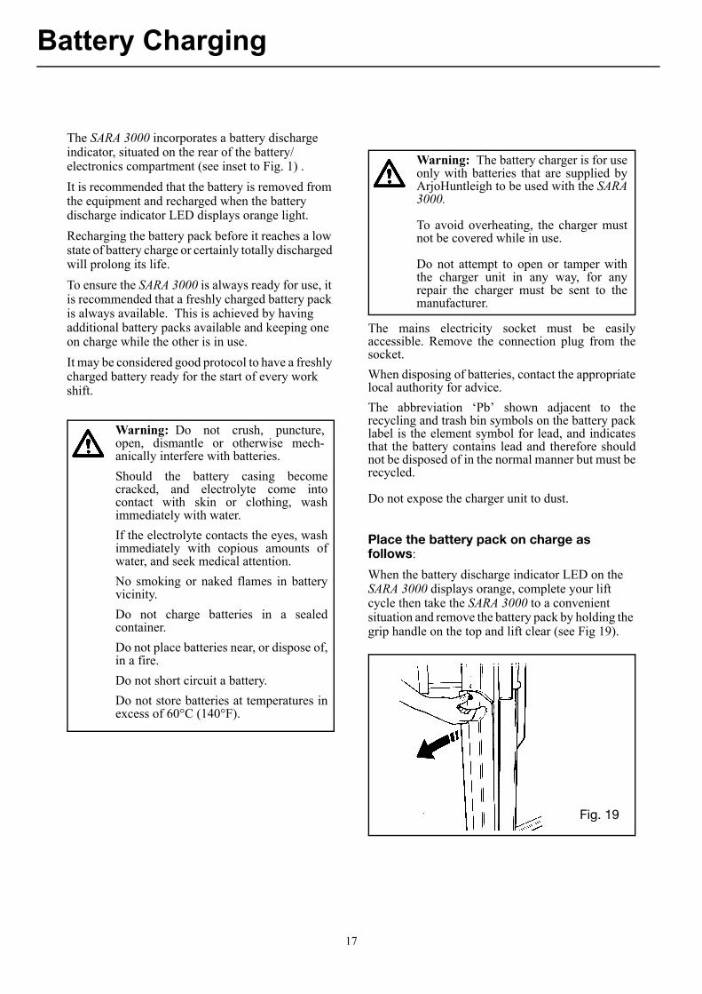
The scale will display ‘NET 0.0’ (see Fig. 17).
Remove the sling and position it around the resident, as in normal raising procedure.
Raise the resident until clear of any obstructions e.g. bed, chair, floor etc.
Do not press the button again - the number displayed will be the weight of the resident.
For European scales only: If the word TILT appears on the display, move the SARA 3000 to a position where the floor surface is on a level acceptable for the scale to operate correctly.
Do not touch or lean on the resident, or the SARA 3000 itself during the weighing operation, as the mast and resident support arms are integral parts of the weighing equipment.
The scale, once switched on will operate for 6 minutes. After this time, the scale will automatically switch off. If this happens, press the button again.
The scale can be ‘re-netted’ during operation.
Method ‘B’- Weighing with the resident already standing on the footrest.
Ensure the resident is raised and clear of anyobstructions, e.g. bed, chair, floor etc.
Press the scale operating button (see Fig. 16).
With agitated residents, the caregiver shall wait untilthe resident is calm before attempting to weigh.
A display test will be performed, all displaysegments are shown for approximately one second.
Scale Operating Button Fig. 16
Fig. 1Fig 17
Caution: Do not overload the scale. Ifthe scale unit displays ‘MAX’, lower theresident immediately onto a bed/chair.
Caution: Do NOT hold the scaledisplay unit or the mounting tube to assistin manoeuvring the SARA 3000.
15

Scale
The display will show ‘WAIT’ and after some seconds will display the mode that the scale is in.
Ignore the weight displayed, and press the operating button again.
The scale will display “NET 0.0” (see Fig. 17).
Lower the resident to a suitable position and remove the sling.
Hang the sling over the resident support arm only.
The weight is displayed, and, although having a minus (-) sign in front of it, is the weight of the resident.
Remove the sling.
If the word TILT appears on the display, move the SARA 3000 to a position where the floor surface is on a level acceptable for the scale to operate correctly.
The scale, once switched on will operate for 6 minutes. After this time, the scale will automatically switch off. shall this happen, press the button again.
Do not touch or lean on the resident, or the SARA 3000 itself during the weighing operation. Ensure that no part of the resident touches the mast or resident support arms during weighing, as the resident support arms are an integral part of the weighing equipment.
The scale can be re-netted during operation.
Scale battery installation/change
If the battery symbol is displayed on the scale LCD, there is enough power left for approximately 1 hour of operation.
To change the batteries:
Open the battery compartment cover, by firstly removing the two screws using a small bladed screwdriver. Remove the cover.
Pull out the battery holder carefully.
Disconnect the push-on connector from the end of the battery holder if necessary.
Remove the existing batteries from the battery holder and replace using four “AA” size batteries or equivalent, ensuring correct polarity (shown on the holder).
Replace the battery holder and refit the battery compartment cover and tighten the screws.
If the batteries are inserted incorrectly, this will not damage the circuit board.
Rechargeable batteries may be used, however, the operating time of the scale between charges will be shorter than if non-re-chargeable batteries are used
Care of your scale
The scale is adapted to the same conditions as the SARA 3000. For cleaning instructions see the ‘Disinfection, cleaning and maintenance’ section in the main operating instructions issued for your SARA 3000.
Apart from cleaning and battery changing, no other special maintenance shall be required.
Caution: Do not overload the scale. Ifthe scale displays ‘MAX’, lower theresident immediately onto a bed or chair.
Caution: Do NOT hold the scaledisplay unit or the mounting tube to assistin manoeuvring the SARA 3000.
Push-on connector
4 Batteries Cover
Battery holder
Fig. 18
16
Battery Charging
The SARA 3000 incorporates a battery discharge indicator, situated on the rear of the battery/electronics compartment (see inset to Fig. 1) .
It is recommended that the battery is removed from the equipment and recharged when the battery discharge indicator LED displays orange light.
Recharging the battery pack before it reaches a low state of battery charge or certainly totally discharged will prolong its life.
To ensure the SARA 3000 is always ready for use, it is recommended that a freshly charged battery pack is always available. This is achieved by having additional battery packs available and keeping one on charge while the other is in use.
It may be considered good protocol to have a freshly charged battery ready for the start of every work shift.
The mains electricity socket must be easilyaccessible. Remove the connection plug from thesocket.
When disposing of batteries, contact the appropriatelocal authority for advice.
The abbreviation ‘Pb’ shown adjacent to therecycling and trash bin symbols on the battery packlabel is the element symbol for lead, and indicatesthat the battery contains lead and therefore shouldnot be disposed of in the normal manner but must berecycled.
Do not expose the charger unit to dust.
Place the battery pack on charge as follows:
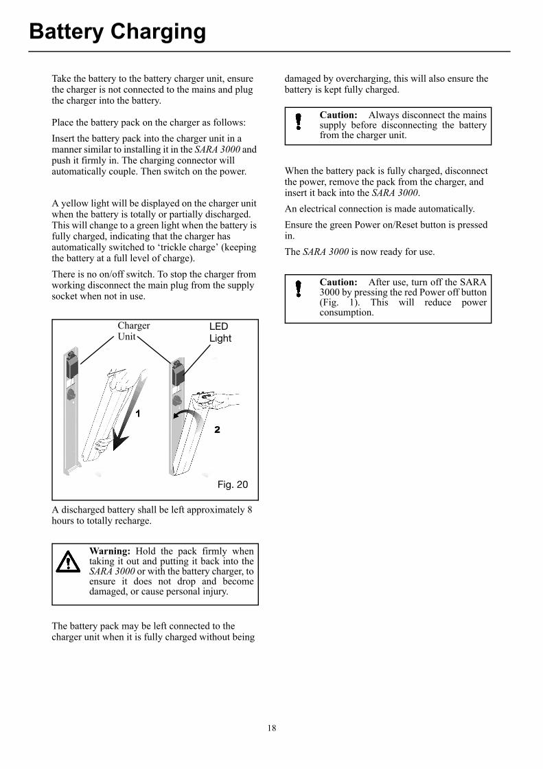
When the battery discharge indicator LED on the SARA 3000 displays orange, complete your lift cycle then take the SARA 3000 to a convenient situation and remove the battery pack by holding the grip handle on the top and lift clear (see Fig 19).
Warning: Do not crush, puncture,open, dismantle or otherwise mech-anically interfere with batteries.
Should the battery casing becomecracked, and electrolyte come intocontact with skin or clothing, washimmediately with water.
If the electrolyte contacts the eyes, washimmediately with copious amounts ofwater, and seek medical attention.
No smoking or naked flames in batteryvicinity.
Do not charge batteries in a sealedcontainer.
Do not place batteries near, or dispose of,in a fire.
Do not short circuit a battery.
Do not store batteries at temperatures inexcess of 60°C (140°F).
Warning: The battery charger is for useonly with batteries that are supplied byArjoHuntleigh to be used with the SARA3000.
To avoid overheating, the charger mustnot be covered while in use.
Do not attempt to open or tamper withthe charger unit in any way, for anyrepair the charger must be sent to themanufacturer.
Fig. 19
17
Battery Charging
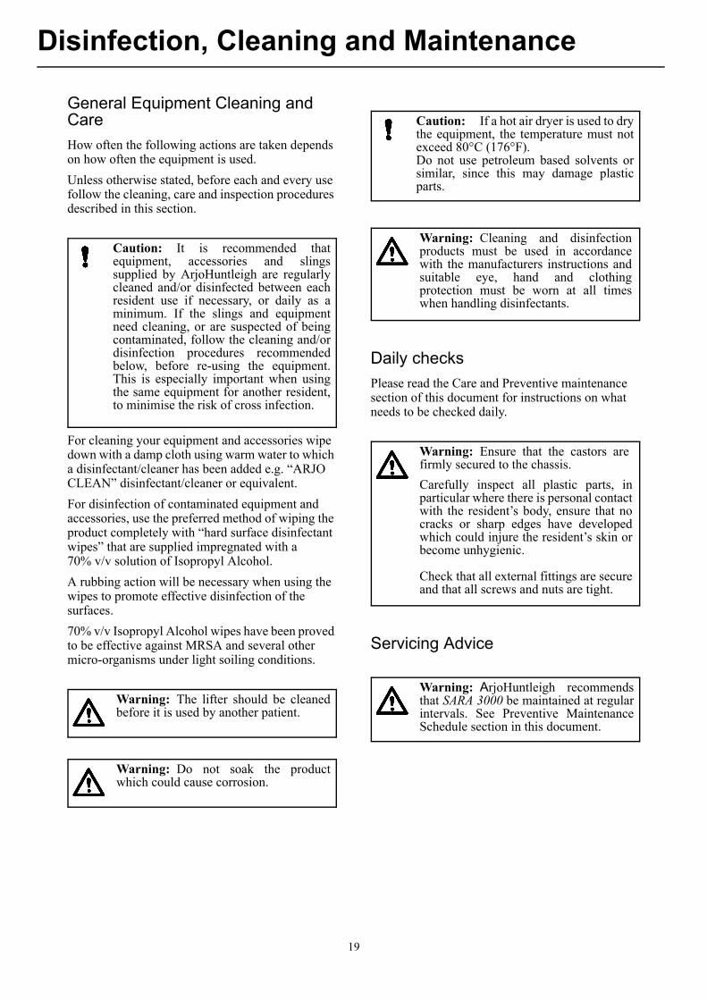
Take the battery to the battery charger unit, ensure the charger is not connected to the mains and plug the charger into the battery.
Place the battery pack on the charger as follows:
Insert the battery pack into the charger unit in a manner similar to installing it in the SARA 3000 and push it firmly in. The charging connector will automatically couple. Then switch on the power.
A yellow light will be displayed on the charger unit when the battery is totally or partially discharged. This will change to a green light when the battery is fully charged, indicating that the charger has automatically switched to ‘trickle charge’ (keeping the battery at a full level of charge).
There is no on/off switch. To stop the charger from working disconnect the main plug from the supply socket when not in use.
A discharged battery shall be left approximately 8 hours to totally recharge.
The battery pack may be left connected to the charger unit when it is fully charged without being
damaged by overcharging, this will also ensure the battery is kept fully charged.
When the battery pack is fully charged, disconnect the power, remove the pack from the charger, and insert it back into the SARA 3000.
An electrical connection is made automatically.
Ensure the green Power on/Reset button is pressed in.
The SARA 3000 is now ready for use.
ChargerUnit
LEDLight
Fig. 20
Warning: Hold the pack firmly whentaking it out and putting it back into theSARA 3000 or with the battery charger, toensure it does not drop and becomedamaged, or cause personal injury.
Caution: Always disconnect the mainssupply before disconnecting the batteryfrom the charger unit.
Caution: After use, turn off the SARA3000 by pressing the red Power off button(Fig. 1). This will reduce powerconsumption.
18
Disinfection, Cleaning and Maintenance
General Equipment Cleaning and Care
How often the following actions are taken depends on how often the equipment is used.
Unless otherwise stated, before each and every use follow the cleaning, care and inspection procedures described in this section.
For cleaning your equipment and accessories wipe down with a damp cloth using warm water to which a disinfectant/cleaner has been added e.g. “ARJO CLEAN” disinfectant/cleaner or equivalent.
For disinfection of contaminated equipment and accessories, use the preferred method of wiping the product completely with “hard surface disinfectant wipes” that are supplied impregnated with a 70% v/v solution of Isopropyl Alcohol.
A rubbing action will be necessary when using the wipes to promote effective disinfection of the surfaces.
70% v/v Isopropyl Alcohol wipes have been proved to be effective against MRSA and several other micro-organisms under light soiling conditions.
Daily checks
Please read the Care and Preventive maintenance section of this document for instructions on what needs to be checked daily.
Servicing Advice
Caution: It is recommended thatequipment, accessories and slingssupplied by ArjoHuntleigh are regularlycleaned and/or disinfected between eachresident use if necessary, or daily as aminimum. If the slings and equipmentneed cleaning, or are suspected of beingcontaminated, follow the cleaning and/ordisinfection procedures recommendedbelow, before re-using the equipment.This is especially important when usingthe same equipment for another resident,to minimise the risk of cross infection.
Warning: The lifter should be cleanedbefore it is used by another patient.
Warning: Do not soak the productwhich could cause corrosion.
Caution: If a hot air dryer is used to drythe equipment, the temperature must notexceed 80°C (176°F).Do not use petroleum based solvents orsimilar, since this may damage plasticparts.
Warning: Cleaning and disinfectionproducts must be used in accordancewith the manufacturers instructions andsuitable eye, hand and clothingprotection must be worn at all timeswhen handling disinfectants.
Warning: Ensure that the castors arefirmly secured to the chassis.
Carefully inspect all plastic parts, inparticular where there is personal contactwith the resident’s body, ensure that nocracks or sharp edges have developedwhich could injure the resident’s skin orbecome unhygienic.
Check that all external fittings are secureand that all screws and nuts are tight.
Warning: ArjoHuntleigh recommendsthat SARA 3000 be maintained at regularintervals. See Preventive MaintenanceSchedule section in this document.
19
Disinfection, Cleaning and Maintenance
Parts lists and circuit diagrams
These are available on request from ArjoHuntleigh or its approved distributors.
Spare parts, if required, are available fromArjoHuntleigh or its approved distributors.
Special tools are required for certain componentreplacement.
Periodic Testing
To be carried out at weekly intervals:
For normal operation - raise and lower the resident support arms using the control handset and dual control switch, this is to test for full and efficient movement.
Emergency Stop:Test the emergency stop facility by operating the control handset to raise or lower the resident support arms, and whilst operating, press in the emergency stop button. (See inset to Fig. 1). Powered movement should stop immediately.
Reset to normal function by resetting out the button.
Repeat this test using the dual control switch.
Adjustable Width Chassis Function:Open and close the chassis legs to check for full and efficient movement.
General Equipment Condition:A general visual inspection of all external parts should be carried out, and all functions should be tested for correct operation, to ensure that no adverse damage has occurred during use.
Environmental Advice
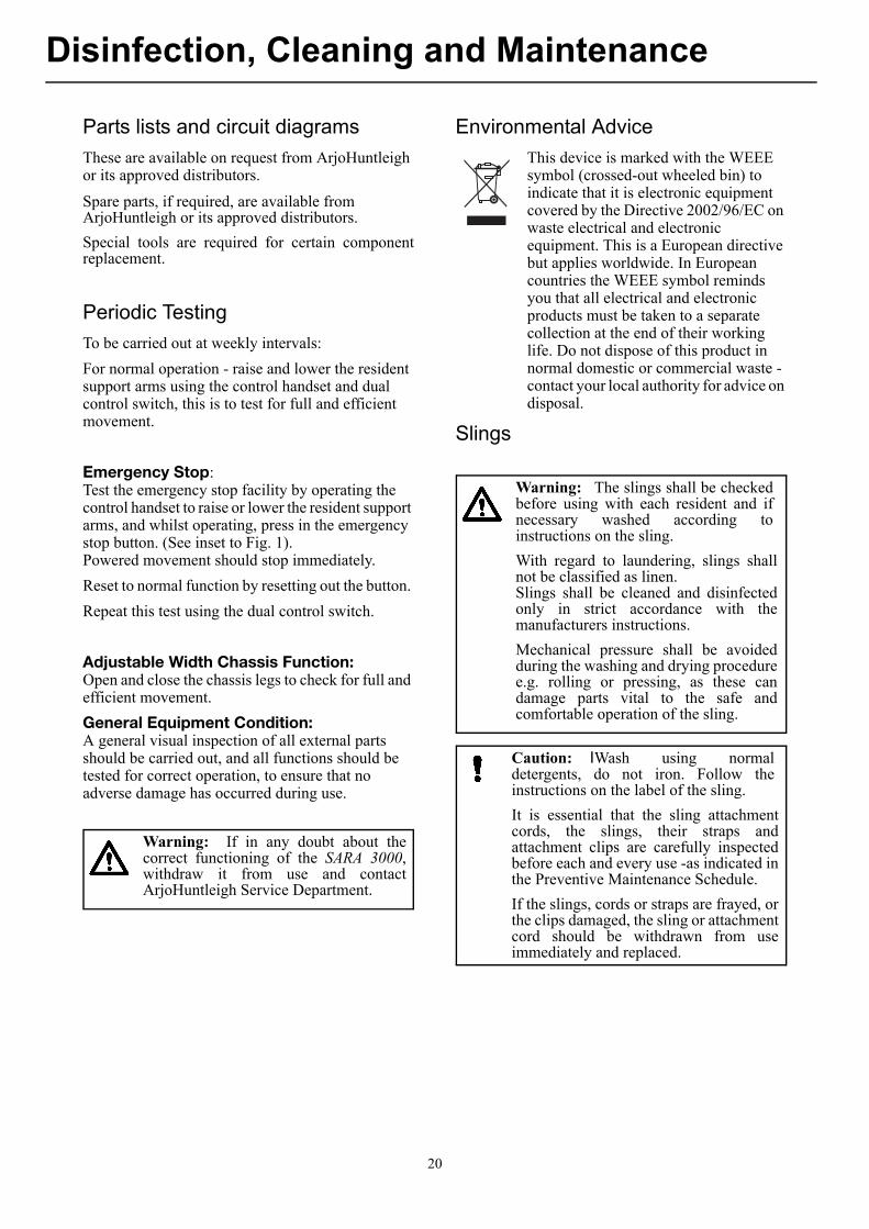
This device is marked with the WEEE symbol (crossed-out wheeled bin) to indicate that it is electronic equipment covered by the Directive 2002/96/EC on waste electrical and electronic equipment. This is a European directive but applies worldwide. In European countries the WEEE symbol reminds you that all electrical and electronic products must be taken to a separate collection at the end of their working life. Do not dispose of this product in normal domestic or commercial waste - contact your local authority for advice on disposal.
Slings
Warning: If in any doubt about thecorrect functioning of the SARA 3000,withdraw it from use and contactArjoHuntleigh Service Department.
Warning: The slings shall be checkedbefore using with each resident and ifnecessary washed according toinstructions on the sling.
With regard to laundering, slings shallnot be classified as linen. Slings shall be cleaned and disinfectedonly in strict accordance with themanufacturers instructions.
Mechanical pressure shall be avoidedduring the washing and drying proceduree.g. rolling or pressing, as these candamage parts vital to the safe andcomfortable operation of the sling.
Caution: IWash using normaldetergents, do not iron. Follow theinstructions on the label of the sling.
It is essential that the sling attachmentcords, the slings, their straps andattachment clips are carefully inspectedbefore each and every use -as indicated inthe Preventive Maintenance Schedule.
If the slings, cords or straps are frayed, orthe clips damaged, the sling or attachmentcord should be withdrawn from useimmediately and replaced.
20
Care and Preventive Maintenance
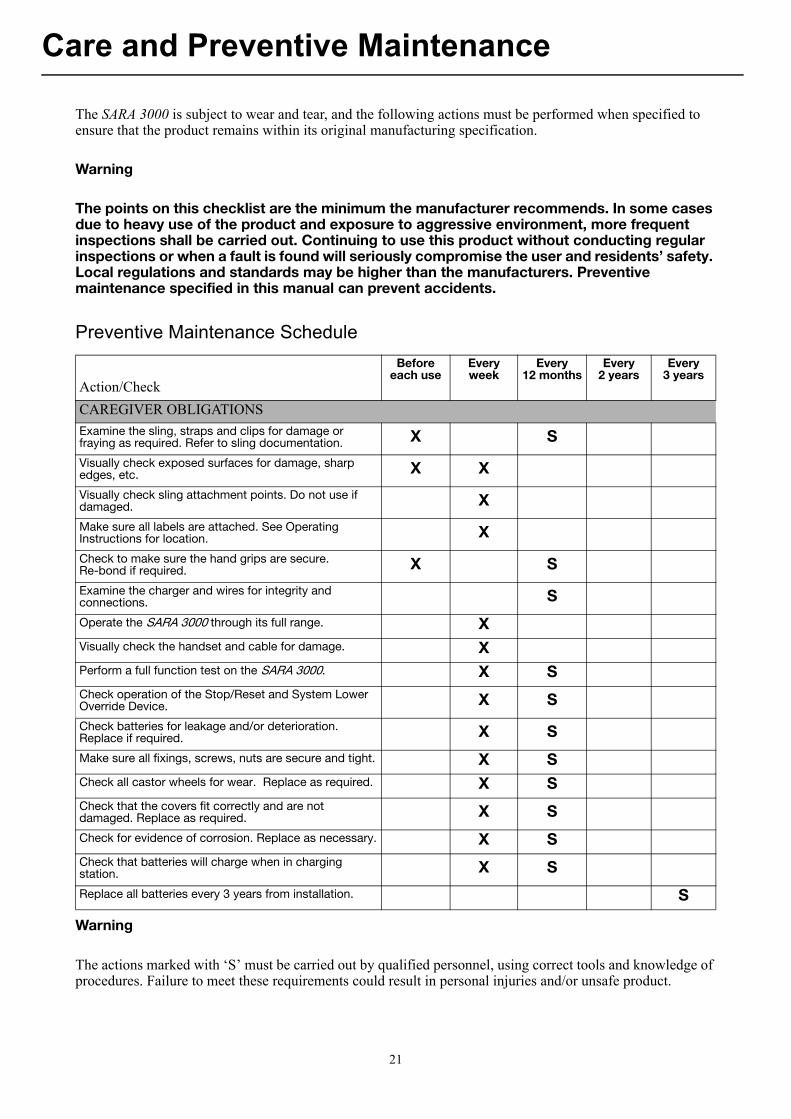
The SARA 3000 is subject to wear and tear, and the following actions must be performed when specified to ensure that the product remains within its original manufacturing specification.
Warning
The points on this checklist are the minimum the manufacturer recommends. In some cases due to heavy use of the product and exposure to aggressive environment, more frequent inspections shall be carried out. Continuing to use this product without conducting regular inspections or when a fault is found will seriously compromise the user and residents’ safety. Local regulations and standards may be higher than the manufacturers. Preventive maintenance specified in this manual can prevent accidents.
Preventive Maintenance Schedule
Warning
The actions marked with ‘S’ must be carried out by qualified personnel, using correct tools and knowledge of procedures. Failure to meet these requirements could result in personal injuries and/or unsafe product.
Action/Check
Before each use
Every week
Every12 months
Every2 years
Every3 years
CAREGIVER OBLIGATIONS
Examine the sling, straps and clips for damage or fraying as required. Refer to sling documentation. X S
Visually check exposed surfaces for damage, sharp edges, etc. X X
Visually check sling attachment points. Do not use if damaged. X
Make sure all labels are attached. See Operating Instructions for location. X
Check to make sure the hand grips are secure.Re-bond if required. X S
Examine the charger and wires for integrity and connections. S
Operate the SARA 3000 through its full range. XVisually check the handset and cable for damage. XPerform a full function test on the SARA 3000. X SCheck operation of the Stop/Reset and System Lower Override Device. X S
Check batteries for leakage and/or deterioration. Replace if required. X S
Make sure all fixings, screws, nuts are secure and tight. X SCheck all castor wheels for wear. Replace as required. X SCheck that the covers fit correctly and are not damaged. Replace as required. X S
Check for evidence of corrosion. Replace as necessary. X SCheck that batteries will charge when in charging station. X S
Replace all batteries every 3 years from installation. S
21
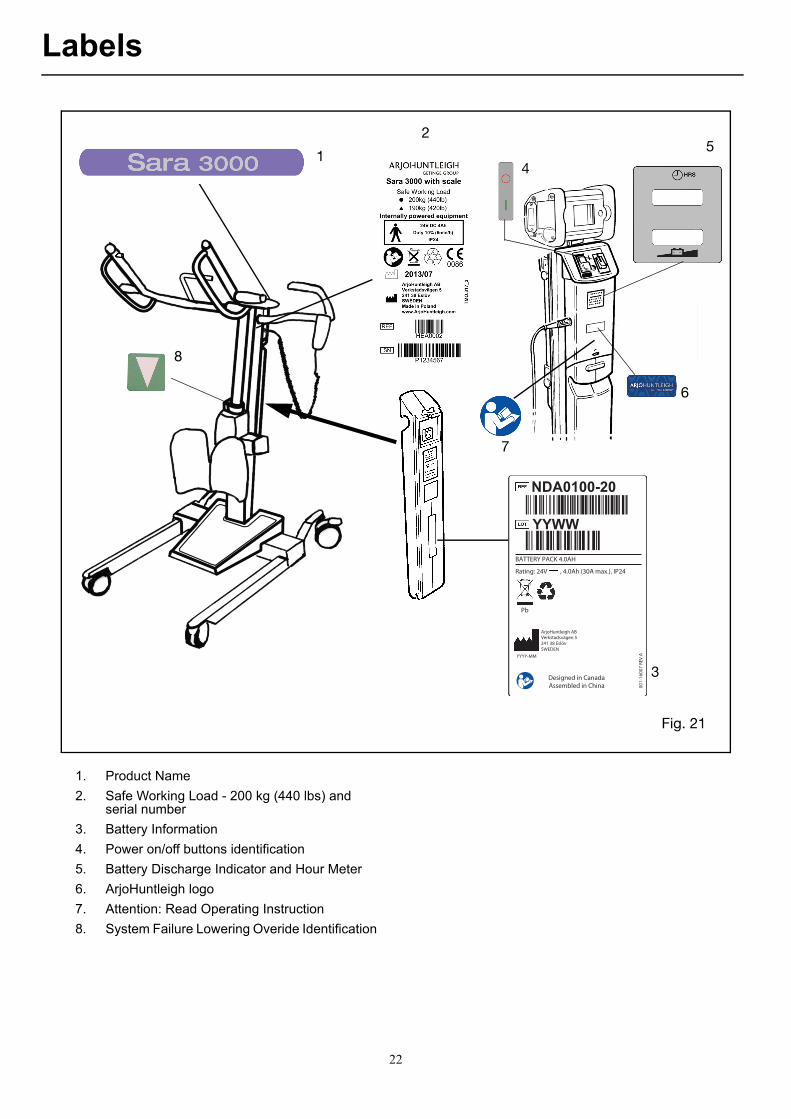
Labels
Rating: 24V , 4.0Ah (30A max.), IP24
BATTERY PACK 4.0AH
Pb
Designed in Canada
Assembled in China 00
1-1
60
07
RE
V AYYYY-MM
ArjoHuntleigh ABVerkstadsvägen 5241 38 EslövSWEDEN
YYWW
NDA0100-20
1
2
3
4
7
Fig. 21
5
6
8
1. Product Name
2. Safe Working Load - 200 kg (440 lbs) and serial number
3. Battery Information
4. Power on/off buttons identification
5. Battery Discharge Indicator and Hour Meter
6. ArjoHuntleigh logo
7. Attention: Read Operating Instruction
8. System Failure Lowering Overide Identification
22
Technical Specification
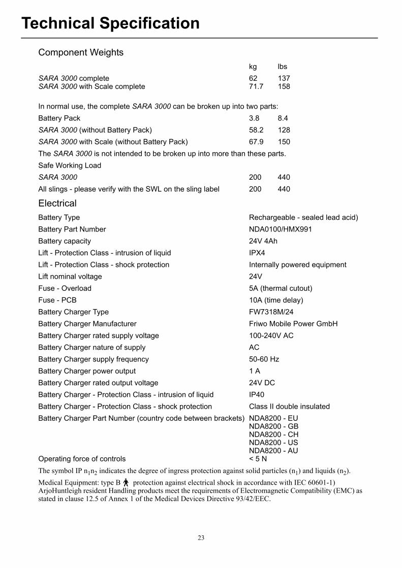
Component Weights
kg lbs
SARA 3000 complete 62 137SARA 3000 with Scale complete 71.7 158
In normal use, the complete SARA 3000 can be broken up into two parts:
Battery Pack 3.8 8.4
SARA 3000 (without Battery Pack) 58.2 128
SARA 3000 with Scale (without Battery Pack) 67.9 150
The SARA 3000 is not intended to be broken up into more than these parts.
Safe Working Load
SARA 3000 200 440
All slings - please verify with the SWL on the sling label 200 440
Electrical
Battery Type Rechargeable - sealed lead acid)
Battery Part Number NDA0100/HMX991
Battery capacity 24V 4Ah
Lift - Protection Class - intrusion of liquid IPX4
Lift - Protection Class - shock protection Internally powered equipment
Lift nominal voltage 24V
Fuse - Overload 5A (thermal cutout)
Fuse - PCB 10A (time delay)
Battery Charger Type FW7318M/24
Battery Charger Manufacturer Friwo Mobile Power GmbH
Battery Charger rated supply voltage 100-240V AC
Battery Charger nature of supply AC
Battery Charger supply frequency 50-60 Hz
Battery Charger power output 1 A
Battery Charger rated output voltage 24V DC
Battery Charger - Protection Class - intrusion of liquid IP40
Battery Charger - Protection Class - shock protection Class II double insulated
Battery Charger Part Number (country code between brackets) NDA8200 - EUNDA8200 - GBNDA8200 - CHNDA8200 - USNDA8200 - AU
Operating force of controls < 5 N
The symbol IP n1n2 indicates the degree of ingress protection against solid particles (n1) and liquids (n2).
Medical Equipment: type B protection against electrical shock in accordance with IEC 60601-1)ArjoHuntleigh resident Handling products meet the requirements of Electromagnetic Compatibility (EMC) as stated in clause 12.5 of Annex 1 of the Medical Devices Directive 93/42/EEC.
23
Technical Specification
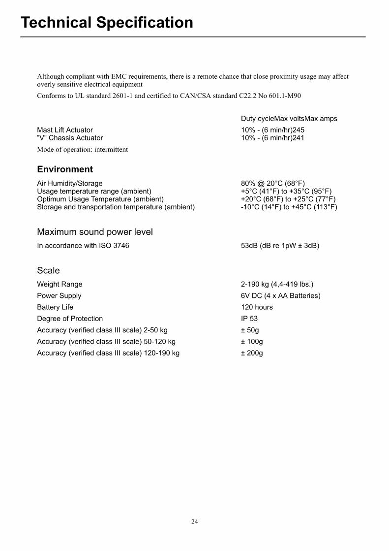
Although compliant with EMC requirements, there is a remote chance that close proximity usage may affect overly sensitive electrical equipment
Conforms to UL standard 2601-1 and certified to CAN/CSA standard C22.2 No 601.1-M90
Duty cycleMax voltsMax amps
Mast Lift Actuator 10% - (6 min/hr)245”V” Chassis Actuator 10% - (6 min/hr)241
Mode of operation: intermittent
Environment
Air Humidity/Storage 80% @ 20°C (68°F)Usage temperature range (ambient) +5°C (41°F) to +35°C (95°F)Optimum Usage Temperature (ambient) +20°C (68°F) to +25°C (77°F)Storage and transportation temperature (ambient) -10°C (14°F) to +45°C (113°F)
Maximum sound power level
In accordance with ISO 3746 53dB (dB re 1pW ± 3dB)
Scale
Weight Range 2-190 kg (4,4-419 lbs.)
Power Supply 6V DC (4 x AA Batteries)
Battery Life 120 hours
Degree of Protection IP 53
Accuracy (verified class III scale) 2-50 kg ± 50g
Accuracy (verified class III scale) 50-120 kg ± 100g
Accuracy (verified class III scale) 120-190 kg ± 200g
24
Technical Specification
Abb.Dimensions:- A. Max. Height of C.S.P. : 1700 mm I. Chassis Footplate /-support Length : 270 mm
: 66.9” : 10.6”
B. Raising / Lifting Range : 795 mm J. Chassis Min. Internal Width : 540 mm: 31.3” : 21.3”
C. Min. Height of C.S.P. : 905 mm K. Chassis Min. External Width : 640 mm: 35.6” : 25.2”
D. Height : 1140 mm L. Chassis Max. Internal Width : 890 mm: 44.9” : 35”
E. Chassis Min. Clearance : 45 mm M. Chassis Max. External Width : 990 mm: 1.8” : 39”
F. Chassis Max. Height : 110 mm N. lifting Reach Min. Height C.S.P. : 500 mm: 4.3” (N is also Max. lifting Reach) : 19.7”
G. Chassis Total External Length : 1035 mm O. lifting Reach Max. Height C.S.P. : 30 mm: 40.7” : 1.2”
H. Chassis Max. Internal Length : 625 mm P. Turning circle : 1035 mm: 24.6” : 40.7”
‘C.S.P.’ stands for ‘Central Suspension Point’ : a reference point on the SARA 3000 used for measurements. AsCSP on the SARA 3000 we have used the clips attachment point closest to the resident at the start of the raisingcycle.
Technical specifications may be revised and changed without prior notice.
Fig. 22
25
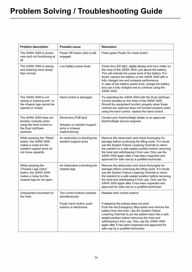
Problem Solving / Troubleshooting Guide
Problem description Possible cause Resolution
The SARA 3000 is (brand new and) not functioning at all
Power Off button (red) is still engaged
Press green Power On /reset button.
The SARA 3000 is raising and lowering more slowly than normal.
Low battery power level. Check the LED light, digital display and hour meter on the mast of the SARA 3000, just above the battery. This will indicate the power level of the battery. If in doubt, replace the battery on the SARA 3000 with a fully charged one and compare performance.In case of low battery power level, charge the battery and use a fully charged one to continue using the SARA 3000.
The SARA 3000 is not raising or lowering and / or the chassis legs cannot be opened or closed.
Hand control is damaged Try operating the SARA 3000 with the Dual Up/Down Control situated on the mast of the SARA 3000. Should the equipment function properly when these controls are used but does not function properly when using the hand control, replace the hand control.
The SARA 3000 does not function correctly when using the hand control or the Dual Up/Down switches.
Electronics PCB fault
Actuator on resident support arms or chassis malfunctioning
Contact your ArjoHuntleigh dealer or an approved ArjoHuntleigh service engineer.
While pressing the “Raise” button, the SARA 3000 makes a noise but the resident support arms do not move upwards.
An obstruction is blocking the resident support arms
Remove the obstruction and check thoroughly for damage before continuing the lifting cycle. If in doubt, use the System Failure Lowering Override to return the resident to a safe seated position before removing the hoist and withdrawing it from use. Only use the SARA 3000 again after it has been inspected and approved for safe use by a qualified technician.
While pressing the “Chassis Legs Open” button, the SARA 3000 makes a noise but the chassis legs do not open.
An obstruction is blocking the chassis legs
Remove the obstruction and check thoroughly for damage before continuing the lifting cycle. If in doubt, use the System Failure Lowering Override to return the resident to a safe seated position before removing the hoist and withdrawing it from use. Only use the SARA 3000 again after it has been inspected and approved for safe use by a qualified technician.
Unexpected movement of the hoist
Two control buttons pressed simultaneously
Faulty hand control, push buttons or electronics.
Release both control buttons
If releasing the buttons does not work:Push the red Emergency Stop button and remove the battery from the hoist. Use the System Failure Lowering Override to put the patient back into a safe seated position before removing the hoist and withdrawing it from use. Only use the SARA 3000 again after it has been inspected and approved for safe use by a qualified technician.
26
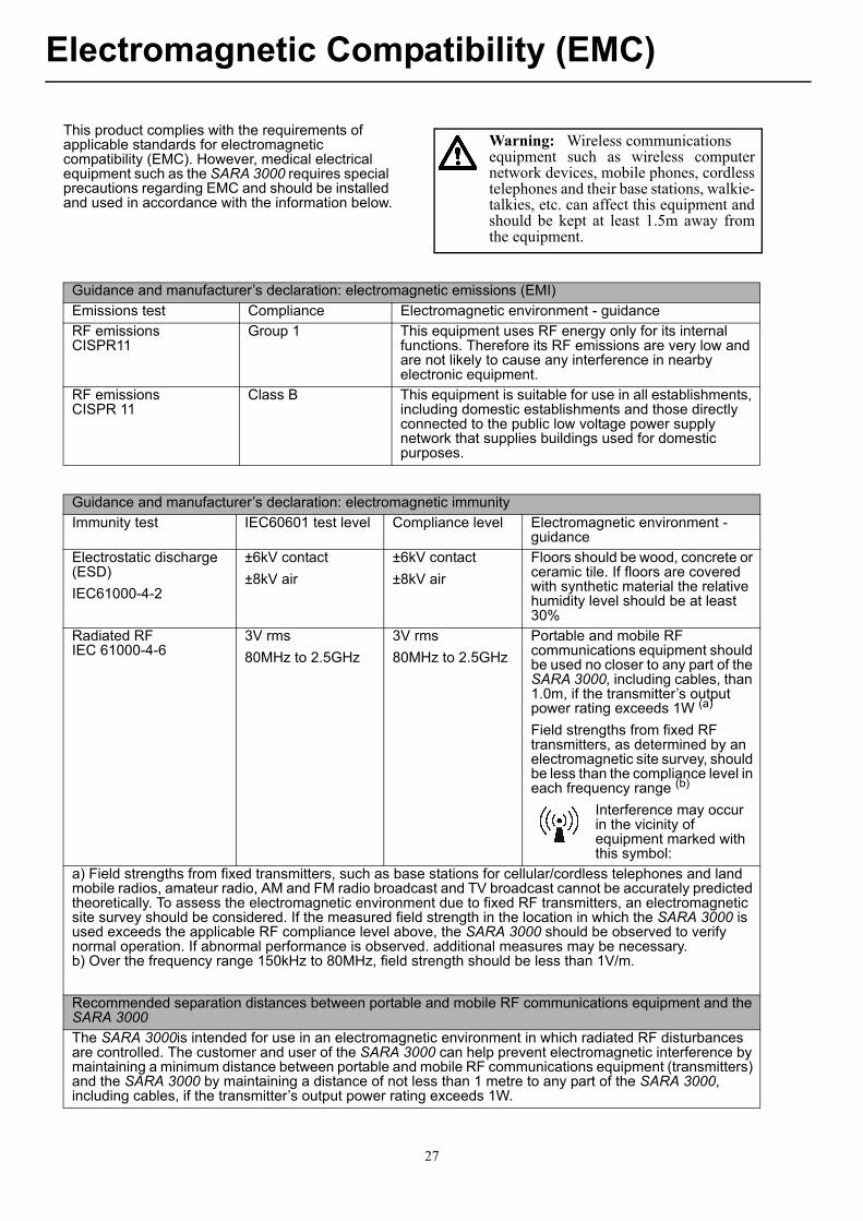
Electromagnetic Compatibility (EMC)
This product complies with the requirements of applicable standards for electromagnetic compatibility (EMC). However, medical electrical equipment such as the SARA 3000 requires special precautions regarding EMC and should be installed and used in accordance with the information below.
Warning: Wireless communicationsequipment such as wireless computernetwork devices, mobile phones, cordlesstelephones and their base stations, walkie-talkies, etc. can affect this equipment andshould be kept at least 1.5m away fromthe equipment.
Guidance and manufacturer’s declaration: electromagnetic emissions (EMI)
Emissions test Compliance Electromagnetic environment - guidance
RF emissionsCISPR11
Group 1 This equipment uses RF energy only for its internal functions. Therefore its RF emissions are very low and are not likely to cause any interference in nearby electronic equipment.
RF emissionsCISPR 11
Class B This equipment is suitable for use in all establishments, including domestic establishments and those directly connected to the public low voltage power supply network that supplies buildings used for domestic purposes.
Guidance and manufacturer’s declaration: electromagnetic immunity
Immunity test IEC60601 test level Compliance level Electromagnetic environment - guidance
Electrostatic discharge (ESD)
IEC61000-4-2
±6kV contact
±8kV air
±6kV contact
±8kV air
Floors should be wood, concrete or ceramic tile. If floors are covered with synthetic material the relative humidity level should be at least 30%
Radiated RFIEC 61000-4-6
3V rms
80MHz to 2.5GHz
3V rms
80MHz to 2.5GHz
Portable and mobile RF communications equipment should be used no closer to any part of the SARA 3000, including cables, than 1.0m, if the transmitter’s output power rating exceeds 1W (a)
Field strengths from fixed RF transmitters, as determined by an electromagnetic site survey, should be less than the compliance level in each frequency range (b)
Interference may occur in the vicinity of equipment marked with this symbol:
a) Field strengths from fixed transmitters, such as base stations for cellular/cordless telephones and land mobile radios, amateur radio, AM and FM radio broadcast and TV broadcast cannot be accurately predicted theoretically. To assess the electromagnetic environment due to fixed RF transmitters, an electromagnetic site survey should be considered. If the measured field strength in the location in which the SARA 3000 is used exceeds the applicable RF compliance level above, the SARA 3000 should be observed to verify normal operation. If abnormal performance is observed. additional measures may be necessary.b) Over the frequency range 150kHz to 80MHz, field strength should be less than 1V/m.
Recommended separation distances between portable and mobile RF communications equipment and the SARA 3000
The SARA 3000is intended for use in an electromagnetic environment in which radiated RF disturbances are controlled. The customer and user of the SARA 3000 can help prevent electromagnetic interference by maintaining a minimum distance between portable and mobile RF communications equipment (transmitters) and the SARA 3000 by maintaining a distance of not less than 1 metre to any part of the SARA 3000, including cables, if the transmitter’s output power rating exceeds 1W.
27

www.arjohuntleigh.com
AUSTRALIAArjoHuntleigh Pty Ltd78, Forsyth StreetO’ConnorAU-6163 Western AustraliaTel: +61 89337 4111Free: +1 800 072 040Fax: + 61 89337 9077
BELGIQUE / BELGIËArjoHuntleigh NV/SAEvenbroekveld 16BE-9420 ERPE-MERETél/Tel: +32 (0) 53 60 73 80Fax: +32 (0) 53 60 73 81E-mail: [email protected]
BRASILMaquet do Brasil Equipamentos Médicos LtdaRua Tenente Alberto Spicciati, 200Barra Funda, 01140-130 SÃO PAULO, SP - BRASILFone: +55 (11) 2608-7400Fax: +55 (11) 2608-7410
CANADAArjoHuntleigh90 Matheson Boulevard WestSuite 300CA-MISSISSAUGA, ON, L5R 3R3Tel/Tél: +1 905 238 7880Free: +1 800 665 4831 InstitutionalFree: +1 800 868 0441 Home CareFax: +1 905 238 7881E-mail: [email protected]
ČESKÁ REPUBLIKAArjoHuntleigh s.r.o.Hlinky 118CZ-603 00 BRNOTel: +420 549 254 252Fax: +420 541 213 550
DANMARKArjoHuntleigh A/SVassingerødvej 52DK-3540 LYNGETel: +45 49 13 84 86Fax: +45 49 13 84 87E-mail: [email protected]
DEUTSCHLANDArjoHuntleigh GmbHPeter-Sander-Strasse 10DE-55252 MAINZ-KASTELTel: +49 (0) 6134 186 0Fax: +49 (0) 6134 186 160E-mail: [email protected]
ESPAÑAArjoHuntleigh Ibérica S.L.Ctra. de Rubí, 88 1ª planta - A108173 Sant Cugat del VallésES- BARCELONA 08173Tel: +34 93 583 11 20Fax: +34 93 583 11 22E-mail: [email protected]
FRANCE ArjoHuntleigh SAS2 Avenue Alcide de GasperiCS 70133FR-59436 RONCQ CEDEXTél: +33 (0) 3 20 28 13 13Fax: +33 (0) 3 20 28 13 14E-mail: [email protected]
HONG KONG ArjoHuntleigh (Hong Kong) Ltd1510-17, 15/F, Tower 2Kowloon Commerce Centre51 Kwai Cheong RoadKwai ChungHONG KONGTel: +852 2207 6363Fax: +852 2207 6368
INTERNATIONALArjoHuntleigh International LtdArjoHuntleigh HouseHoughton Hall ParkHoughton RegisUK-DUNSTABLE LU5 5XFTel: +44 (0) 1582 745 800Fax: +44 (0) 1582 745 866E-mail: [email protected]
ITALIAArjoHuntleigh S.p.A.Via di Tor Vergata 432IT-00133 ROMATel: +39 (0) 6 87426211Fax: +39 (0) 6 87426222E-mail: [email protected]
NEDERLANDArjoHuntleigh Nederland BVBiezenwei 214004 MB TIELPostbus 61164000 HC TIELTel: +31 (0) 344 64 08 00Fax: +31 (0) 344 64 08 85E-mail: [email protected]
NEW ZEALANDArjoHuntleigh Ltd41 Vestey DriveMount WellingtonNZ-AUCKLAND 1060Tel: +64 (0) 9 573 5344Free Call: 0800 000 151Fax: +64 (0) 9 573 5384E-mail: [email protected]
NORGEArjoHuntleigh Norway ASOlaf Helsets vei 5N-0694 OSLOTel: +47 22 08 00 50Faks: +47 22 08 00 51E-mail: [email protected]
ÖSTERREICHArjoHuntleigh GmbHDörrstrasse 85AT-6020 INNSBRUCKTel: +43 (0) 512 204 160 0Fax: +43 (0) 512 204 160 75
POLSKAArjoHuntleigh Polska Sp. z o.o.ul. Ks Piotra Wawrzyniaka 2 PL-62-052 KOMORNIKI (Poznan)Tel: +48 61 662 15 50Fax: +48 61 662 15 90E-mail: [email protected]
PORTUGALArjoHuntleigh em PortugalMAQUET Portugal, Lda. (Distribudor Exclusivo)Rua Poeta Bocage n.º 2 - 2G PT-1600-233 LisboaTel: +351 214 189 815Fax: +351 214 177 413E-mail: [email protected]
SUISSE / SCHWEIZArjoHuntleigh AGFabrikstrasse 8PostfachCH-4614 HÄGENDORFTél/Tel: +41 (0) 61 337 97 77Fax: +41 (0) 61 311 97 42
SUOMIOy Vestek ABMartinkuja 4FI-02270 ESPOOPuh: +358 9 8870 120E-mail: [email protected]
SVERIGEARJO Scandinavia ABHans Michelsensgatan 10SE-211 20 MALMÖTel: +46 (0) 10 494 7760Fax: +46 (0) 10 494 7761E-mail: [email protected]
UNITED KINGDOMArjoHuntleigh UKArjoHuntleigh HouseHoughton Hall ParkHoughton RegisUK-DUNSTABLE LU5 5XFTel: +44 (0) 1582 745 700Fax: +44 (0) 1582 745 745E-mail: [email protected]
USAArjoHuntleigh Inc.2349 W Lake Street Suite 250US-Addison, IL 60101Tel: +1 630 307 2756Free: +1 800 323 1245 InstitutionalFree: +1 800 868 0441 Home CareFax: +1 630 307 6195E-mail: [email protected]
REV 14: 07/2014

GETINGE GROUP is a leading global provider of products and systems that contribute to quality enhancement and cost efficiency within healthcare and life sciences. We operate under the three brands of ArjoHuntleigh, GETINGE and MAQUET. ArjoHuntleigh focuses on patient mobility and wound management solutions. GETINGE provides solutions for infection control within healthcare and contamination prevention within life sciences. MAQUET specializes in solutions, therapies and products for surgical interventions and intensive care.
www.arjohuntleigh.com
ArjoHuntleigh ABHans Michelsensgatan 10211 20 Malmö, Sweden