Embed Size (px)
Citation preview
Sapag Control valve MONOVAR®
© 2012 Pentair plc. all rights reserved.
FeatureS
• Extremely simple design (patented)• Excellent cavitation characteristics• Very accurate flow or pressure control• Manual or automatic control• Suitable for flow measurement• Small sizes are available• Minimum flow disturbance• The flow is divided equally over a larger
number of jets. This ensures an accurate and stable performance
• These unique features, together with the wide range of construction materials make MONOVAR® valves an automatic choice in all severe industrial and water-supply situations requiring fluid flow control or of some associated characteristic, e.g. pressure, temperature and level
• The design suppresses vibration, cavitation, pressure fluctuations and excess noise
• Suitable for high velocity applications• Suitable for high pressure drop applications
general application
Application of MONOVAR®:- Water supply systems (reliability, pressure,
cavitation),- Industrial flow, cooling and mixing systems
(cavitation, sensitivity, pressure, reliability),- Head works of water treatment plant
(reduced civil works, cavitation, reliability),- Laboratory test-rigs (sensitivity, absence
of disturbances),- Turbine bypass (dams),- End of line, free discharge,- Replace variable speed pumps with constant
flow or constant pressure pumps in combination with MONOVAR®,
- Seawater applications on request.
MONOVAR® is the energy dissipating valve
technical data
Size range: DN 100 - DN 2000 (NPS 4 - NPS 80)Pressure range: 50 bar (725 psi)Temperature range: -50° to +200°C (-60°F to +390°F)Flangeaccommodation: EN 1092-1 PN10/16/20/25 ASMEB16.5 class 150 MSS SP 44 class 150 AWWA C207 Others on request
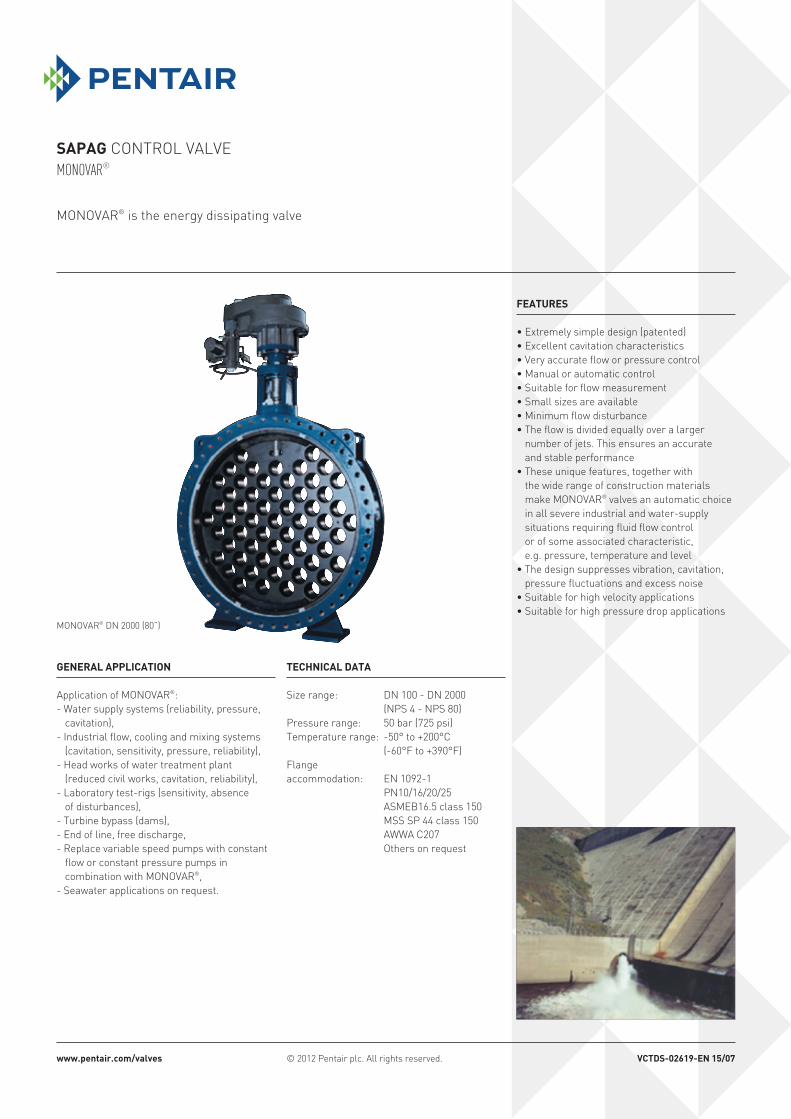
MONOVAR® DN 2000 (80”)
www.pentair.com/valves VctdS-02619-en 15/07
2
Sapag Control valve MONOVAR®
adVantageS
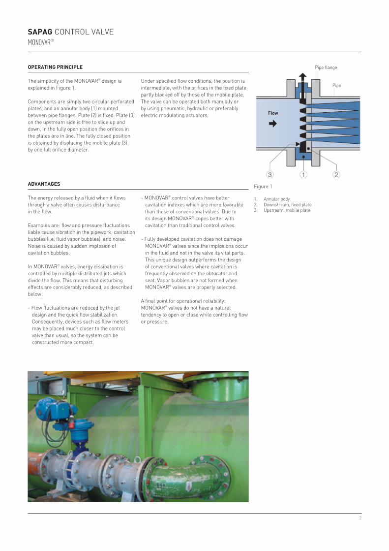
operating principle
Components are simply two circular perforated plates, and an annular body (1) mounted between pipe flanges. Plate (2) is fixed. Plate (3) on the upstream side is free to slide up and down. In the fully open position the orifices in the plates are in line. The fully closed position is obtained by displacing the mobile plate (3) by one full orifice diameter.
Pipe flange
Pipe
Figure 1
1. Annular body2. Downstream, fixed plate3. Upstream, mobile plate
Flow
The simplicity of the MONOVAR® design is explained in Figure 1.
The energy released by a fluid when it flows through a valve often causes disturbance in the flow.
Examples are: flow and pressure fluctuations liable cause vibration in the pipework, cavitation bubbles (i.e. fluid vapor bubbles), and noise. Noise is caused by sudden implosion of cavitation bubbles.
In MONOVAR® valves, energy dissipation is controlled by multiple distributed jets which divide the flow. This means that disturbing effects are considerably reduced, as described below:
- Flow fluctuations are reduced by the jet design and the quick flow stabilization. Consequently, devices such as flow meters may be placed much closer to the control valve than usual, so the system can be constructed more compact.
- MONOVAR® control valves have better cavitation indexes which are more favorable than those of conventional valves. Due to its design MONOVAR® copes better with cavitation than traditional control valves.
- Fully developed cavitation does not damage MONOVAR® valves since the implosions occur in the fluid and not in the valve its vital parts. This unique design outperforms the design of conventional valves where cavitation is frequently observed on the obturator and seat. Vapor bubbles are not formed when MONOVAR® valves are properly selected.
A final point for operational reliability: MONOVAR® valves do not have a natural tendency to open or close while controlling flow or pressure.
Under specified flow conditions, the position is intermediate, with the orifices in the fixed plate partly blocked off by those of the mobile plate.The valve can be operated both manually or by using pneumatic, hydraulic or preferably electric modulating actuators.
3
0
0,2
0,4
0,6
0,8
1
1,2
1,4
0 20 40 60 80
σ
σ =
σ =
q11 =
q11 =
q11 =
q11 = q΄11 = = 0.33 = 0.62
q΄11 =
q11 =
K =
K =
P2 - Pv
1 - K
Q
Q
Q
0.15 0.25
Q΄
P1 - P2
1
V2
2g
π2 g
P1 - P2
K
D2
D2
D2
0.32 0.32
D2
∆H
∆H
∆H
25 20
∆H΄
∆H = k
P1 - PV
1 + σ
8k
σ = P2 - Pv
P1 - P2
K = P1 - P2
P1 - PV
σ =
σ = σ = = 0.99 = 1.39
σ΄ = P2 - Pv
25 - 0.2 28 - 0.2
P΄2 - Pv
P1 - P2
50- 25 48- 28
P1 - P΄2
This section gives a brief overview of the hydraulic design data and selection criteria for MONOVAR® control valves. The data come from measurements made on the Sapag test rigs, from experience gained on Sapag turbine test installations, and from feedback from MONOVAR® users in the industry and in the water resources field.
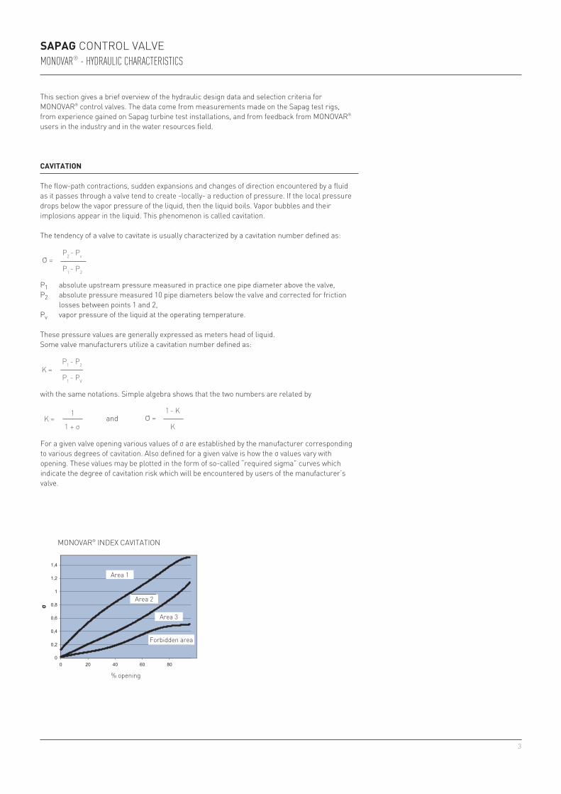
caVitation
The flow-path contractions, sudden expansions and changes of direction encountered by a fluid as it passes through a valve tend to create -locally- a reduction of pressure. If the local pressure drops below the vapor pressure of the liquid, then the liquid boils. Vapor bubbles and their implosions appear in the liquid. This phenomenon is called cavitation.
The tendency of a valve to cavitate is usually characterized by a cavitation number defined as:
P1 absolute upstream pressure measured in practice one pipe diameter above the valve,P2 absolute pressure measured 10 pipe diameters below the valve and corrected for friction
losses between points 1 and 2,Pv vapor pressure of the liquid at the operating temperature.
These pressure values are generally expressed as meters head of liquid.Some valve manufacturers utilize a cavitation number defined as:
with the same notations. Simple algebra shows that the two numbers are related by
For a given valve opening various values of σ are established by the manufacturer corresponding to various degrees of cavitation. Also defined for a given valve is how the σ values vary with opening. These values may be plotted in the form of so-called “required sigma” curves which indicate the degree of cavitation risk which will be encountered by users of the manufacturer’s valve.
MONOVAR® INDEx CAVITATION
% opening
area 1
area 2
Area 3
Forbidden area
and
Sapag Control valve MONOVAR® - HydRAulic cHARActeRistics
σ =
σ =
q11 =
q11 =
q11 =
q11 = q΄11 = = 0.33 = 0.62
q΄11 =
q11 =
K =
K =
P2 - Pv
1 - K
Q
Q
Q
0.15 0.25
Q΄
P1 - P2
1
V2
2g
π2 g
P1 - P2
K
D2
D2
D2
0.32 0.32
D2
∆H
∆H
∆H
25 20
∆H΄
∆H = k
P1 - PV
1 + σ
8k
σ = P2 - Pv
P1 - P2
K = P1 - P2
P1 - PV
σ =
σ = σ = = 0.99 = 1.39
σ΄ = P2 - Pv
25 - 0.2 28 - 0.2
P΄2 - Pv
P1 - P2
50- 25 48- 28
P1 - P΄2
σ =
σ =
q11 =
q11 =
q11 =
q11 = q΄11 = = 0.33 = 0.62
q΄11 =
q11 =
K =
K =
P2 - Pv
1 - K
Q
Q
Q
0.15 0.25
Q΄
P1 - P2
1
V2
2g
π2 g
P1 - P2
K
D2
D2
D2
0.32 0.32
D2
∆H
∆H
∆H
25 20
∆H΄
∆H = k
P1 - PV
1 + σ
8k
σ = P2 - Pv
P1 - P2
K = P1 - P2
P1 - PV
σ =
σ = σ = = 0.99 = 1.39
σ΄ = P2 - Pv
25 - 0.2 28 - 0.2
P΄2 - Pv
P1 - P2
50- 25 48- 28
P1 - P΄2
4
1000k
100
10
10 20 40 60 80 100
100
10
20
40
60
80
10 20 40 60 80 100
1000k
100
10
10 20 40 60 80 100
100
10
20
40
60
80
10 20 40 60 80 100
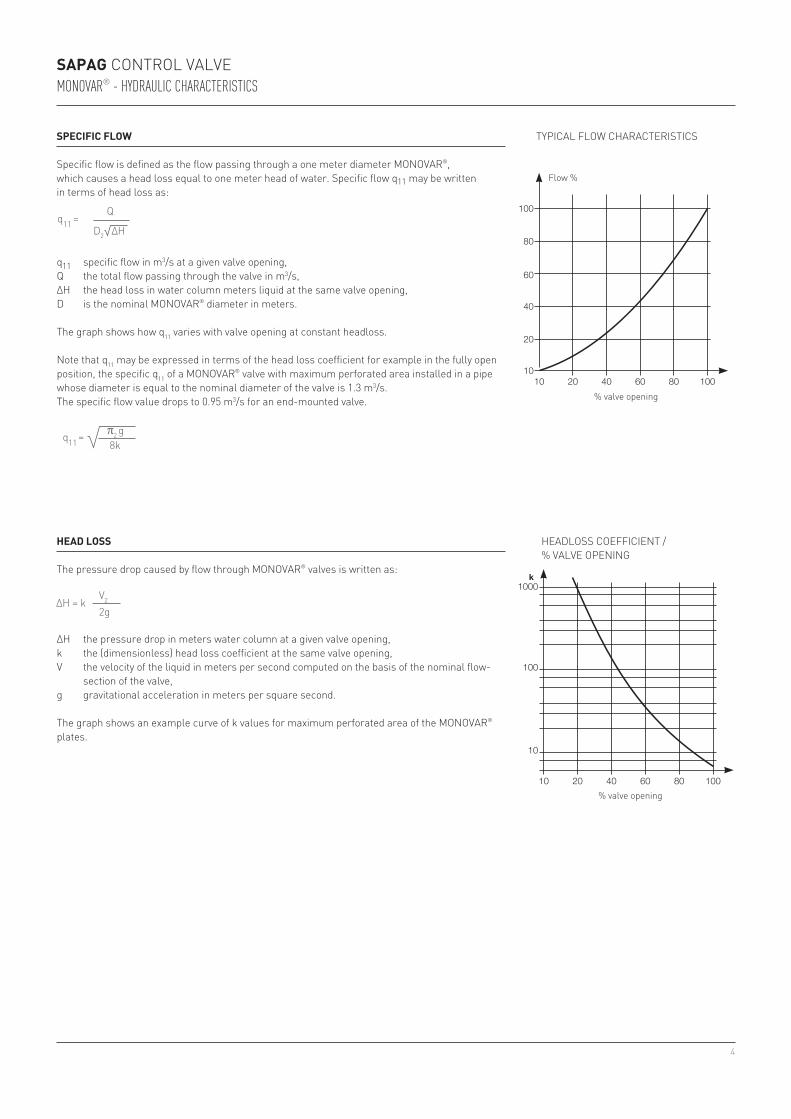
head loSS
The pressure drop caused by flow through MONOVAR® valves is written as:
ΔH the pressure drop in meters water column at a given valve opening,k the (dimensionless) head loss coefficient at the same valve opening,V the velocity of the liquid in meters per second computed on the basis of the nominal flow-
section of the valve,g gravitational acceleration in meters per square second.
The graph shows an example curve of k values for maximum perforated area of the MONOVAR® plates.
SpeciFic Flow
Specific flow is defined as the flow passing through a one meter diameter MONOVAR®, which causes a head loss equal to one meter head of water. Specific flow q11 may be written in terms of head loss as:
q11 specific flow in m3/s at a given valve opening,Q the total flow passing through the valve in m3/s,ΔH the head loss in water column meters liquid at the same valve opening,D is the nominal MONOVAR® diameter in meters.
The graph shows how q11 varies with valve opening at constant headloss.
Note that q11 may be expressed in terms of the head loss coefficient for example in the fully open position, the specific q11 of a MONOVAR® valve with maximum perforated area installed in a pipe whose diameter is equal to the nominal diameter of the valve is 1.3 m3/s.The specific flow value drops to 0.95 m3/s for an end-mounted valve.
TyPICAL FLOW CHARACTERISTICS
Flow %
% valve opening
HEADLOSS COEFFICIENT / % VALVE OPENINg
% valve opening
Sapag Control valve MONOVAR® - HydRAulic cHARActeRistics
σ =
σ =
q11 =
q11 =
q11 =
q11 = q΄11 = = 0.33 = 0.62
q΄11 =
q11 =
K =
K =
P2 - Pv
1 - K
Q
Q
Q
0.15 0.25
Q΄
P1 - P2
1
V2
2g
π2 g
P1 - P2
K
D2
D2
D2
0.32 0.32
D2
∆H
∆H
∆H
25 20
∆H΄
∆H = k
P1 - PV
1 + σ
8k
σ = P2 - Pv
P1 - P2
K = P1 - P2
P1 - PV
σ =
σ = σ = = 0.99 = 1.39
σ΄ = P2 - Pv
25 - 0.2 28 - 0.2
P΄2 - Pv
P1 - P2
50- 25 48- 28
P1 - P΄2
σ =
σ =
q11 =
q11 =
q11 =
q11 = q΄11 = = 0.33 = 0.62
q΄11 =
q11 =
K =
K =
P2 - Pv
1 - K
Q
Q
Q
0.15 0.25
Q΄
P1 - P2
1
V2
2g
π2 g
P1 - P2
K
D2
D2
D2
0.32 0.32
D2
∆H
∆H
∆H
25 20
∆H΄
∆H = k
P1 - PV
1 + σ
8k
σ = P2 - Pv
P1 - P2
K = P1 - P2
P1 - PV
σ =
σ = σ = = 0.99 = 1.39
σ΄ = P2 - Pv
25 - 0.2 28 - 0.2
P΄2 - Pv
P1 - P2
50- 25 48- 28
P1 - P΄2
σ =
σ =
q11 =
q11 =
q11 =
q11 = q΄11 = = 0.33 = 0.62
q΄11 =
q11 =
K =
K =
P2 - Pv
1 - K
Q
Q
Q
0.15 0.25
Q΄
P1 - P2
1
V2
2g
π2 g
P1 - P2
K
D2
D2
D2
0.32 0.32
D2
∆H
∆H
∆H
25 20
∆H΄
∆H = k
P1 - PV
1 + σ
8k
σ = P2 - Pv
P1 - P2
K = P1 - P2
P1 - PV
σ =
σ = σ = = 0.99 = 1.39
σ΄ = P2 - Pv
25 - 0.2 28 - 0.2
P΄2 - Pv
P1 - P2
50- 25 48- 28
P1 - P΄2
5
q11
a
b
c
d
eQ
H1
H2
01
2
– (Ha – Hv)
4 3 2 1
Sapag Control valve MONOVAR® - HydRAulic cHARActeRistics
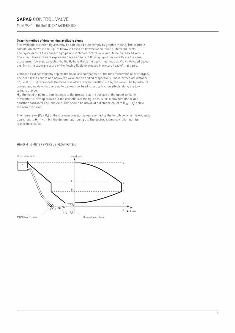
graphic method of determining available sigmaThe available cavitation figures may be calculated quite simply by graphic means. The example calculation shown in the Figure below is based on flow between tanks at different levels. The figure depicts the connecting pipe and included control valve and, to below, a head versus flow chart. Pressures are expressed here as heads of flowing liquid because this is the usual procedure. However, variables H1, H2, Hv have the same basic meanings as P1, P2, Pv cited above, e.g., Hv is the vapor pressure of the flowing liquid expressed in meters head of that liquid.
Vertical a b c d conveniently depicts the head loss components at the maximum value of discharge Q.The head losses above and below the valve are ab and cd respectively. The intermediate distance bc, i.e. (H1 - H2) represents the head loss which may be throttled out by the valve. The (quadratic) curves leading down to b and up to c show how head is lost by friction effects along the two lengths of pipe.Ha, the head at point a, corresponds to the pressure at the surface of the upper tank, I.e. atmospheric. Having drawn out the essentials of the figure thus far, it only remains to add a further horizontal line labeled e. This should be drawn at a distance equal to (Ha - Hv) below the zero head axis.
The numerator (P2 - Pv) of the sigma expression is represented by the length ce, which is evidently equivalent to H2 + Ha - Hv, the denominator being bc. The desired sigma cavitation number is therefore ce/bc.
Upstream tank
HEAD H IN METERS VERSUS FLOW RATE Q
MONOVAR® valve Downstream tank
Headloss
Flow
6
Sapag Control valve MONOVAR® - HydRAulic cHARActeRistics
operating limitS
temperatureMONOVAR® valves made from the standard materials should not be operated outside the temperature range 0 to 80°C. Seal effectiveness may be maintained up to 200°C by using special seal material.Elastomer and plastomer seals cater to low temperatures down to -50°C.The temperature limits above are only approximate and depend on fluid and operating pressure.
pressurePN64 DN 100PN40 DN 150PN25 DN 200 to DN 600PN16 DN 700 to DN 800PN10 DN 900 to DN 2000
tightnessValve is not bubble tight as it is recommended to install the MONOVAR® between two isolation valves.
The MONOVAR® is unidirectional. In case of backflow, please contact factory.
7
Sapag Control valve MONOVAR® - flOw ANd cAVitAtiON cHARActeRistics
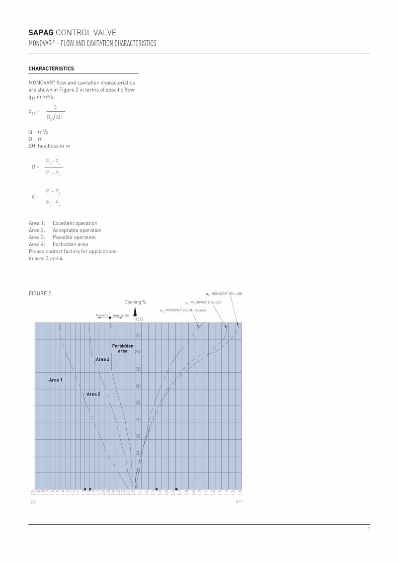
characteriSticS
MONOVAR® flow and cavitation characteristics are shown in Figure 2 in terms of specific flow q11 in m3/s.
Q m3/sD mΔH headloss in m
area 1
area 2
area 3
Forbidden area
FIgURE 2 q11 MONOVAR® DN ≥ 450
q11 MONOVAR® DN ≤ 400
q11 MONOVAR® end of line valve
opening %
Possible Impossible
σ =
σ =
q11 =
q11 =
q11 =
q11 = q΄11 = = 0.33 = 0.62
q΄11 =
q11 =
K =
K =
P2 - Pv
1 - K
Q
Q
Q
0.15 0.25
Q΄
P1 - P2
1
V2
2g
π2 g
P1 - P2
K
D2
D2
D2
0.32 0.32
D2
∆H
∆H
∆H
25 20
∆H΄
∆H = k
P1 - PV
1 + σ
8k
σ = P2 - Pv
P1 - P2
K = P1 - P2
P1 - PV
σ =
σ = σ = = 0.99 = 1.39
σ΄ = P2 - Pv
25 - 0.2 28 - 0.2
P΄2 - Pv
P1 - P2
50- 25 48- 28
P1 - P΄2
σ =
σ =
q11 =
q11 =
q11 =
q11 = q΄11 = = 0.33 = 0.62
q΄11 =
q11 =
K =
K =
P2 - Pv
1 - K
Q
Q
Q
0.15 0.25
Q΄
P1 - P2
1
V2
2g
π2 g
P1 - P2
K
D2
D2
D2
0.32 0.32
D2
∆H
∆H
∆H
25 20
∆H΄
∆H = k
P1 - PV
1 + σ
8k
σ = P2 - Pv
P1 - P2
K = P1 - P2
P1 - PV
σ =
σ = σ = = 0.99 = 1.39
σ΄ = P2 - Pv
25 - 0.2 28 - 0.2
P΄2 - Pv
P1 - P2
50- 25 48- 28
P1 - P΄2
Area 1: Excellent operationArea 2: Acceptable operationArea 3: Possible operationArea 4: Forbidden areaPlease contact factory for applications in area 3 and 4.
8
2. First computation stagecalculate
• if q’11 < 1.3 the MONOVAR® diameter will be less than or equal to D• if q’11 > 1.3 the MONOVAR® diameter will be greater than D,
and the new valve should be chosen so that q’11 ≤ 1.3
σ =
σ =
q11 =
q11 =
q11 =
q11 = q΄11 = = 0.33 = 0.62
q΄11 =
q11 =
K =
K =
P2 - Pv
1 - K
Q
Q
Q
0.15 0.25
Q΄
P1 - P2
1
V2
2g
π2 g
P1 - P2
K
D2
D2
D2
0.32 0.32
D2
∆H
∆H
∆H
25 20
∆H΄
∆H = k
P1 - PV
1 + σ
8k
σ = P2 - Pv
P1 - P2
K = P1 - P2
P1 - PV
σ =
σ = σ = = 0.99 = 1.39
σ΄ = P2 - Pv
25 - 0.2 28 - 0.2
P΄2 - Pv
P1 - P2
50- 25 48- 28
P1 - P΄2
Sapag Control valve MONOVAR® - flOw ANd cAVitAtiON cHARActeRistics
example (water)
• 0.62 < 1.3: the MONOVAR® will therefore have a diameter ≤ 0.3
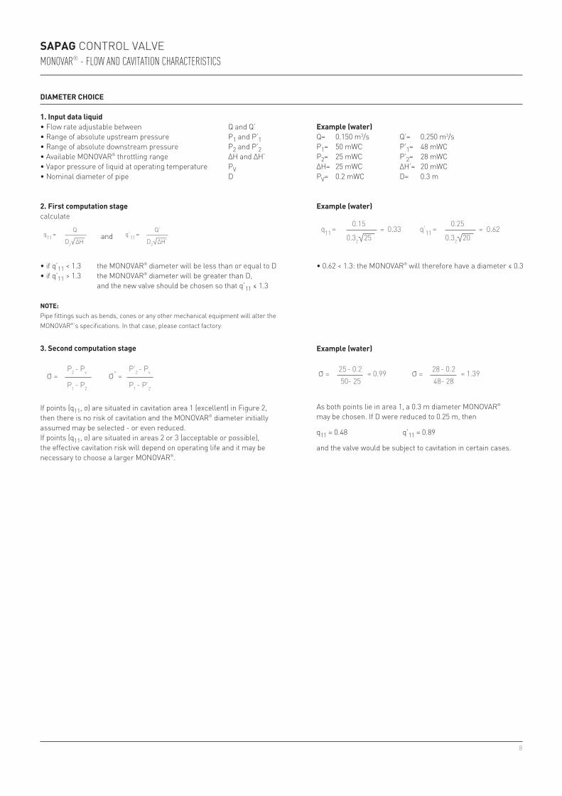
diameter choice
example (water)Q= 0.150 m3/s Q’= 0.250 m3/sP1= 50 mWC P’1= 48 mWCP2= 25 mWC P’2= 28 mWCΔH= 25 mWC ΔH’= 20 mWCPv= 0.2 mWC D= 0.3 m
3. Second computation stage
If points (q11, σ) are situated in cavitation area 1 (excellent) in Figure 2,then there is no risk of cavitation and the MONOVAR® diameter initially assumed may be selected - or even reduced.If points (q11, σ) are situated in areas 2 or 3 (acceptable or possible), the effective cavitation risk will depend on operating life and it may be necessary to choose a larger MONOVAR®.
example (water)
As both points lie in area 1, a 0.3 m diameter MONOVAR® may be chosen. If D were reduced to 0.25 m, then
q11 = 0.48 q’11 = 0.89
and the valve would be subject to cavitation in certain cases.
note: Pipe fittings such as bends, cones or any other mechanical equipment will alter the MONOVAR®’s specifications. In that case, please contact factory.
and
σ =
σ =
q11 =
q11 =
q11 =
q11 = q΄11 = = 0.33 = 0.62
q΄11 =
q11 =
K =
K =
P2 - Pv
1 - K
Q
Q
Q
0.15 0.25
Q΄
P1 - P2
1
V2
2g
π2 g
P1 - P2
K
D2
D2
D2
0.32 0.32
D2
∆H
∆H
∆H
25 20
∆H΄
∆H = k
P1 - PV
1 + σ
8k
σ = P2 - Pv
P1 - P2
K = P1 - P2
P1 - PV
σ =
σ = σ = = 0.99 = 1.39
σ΄ = P2 - Pv
25 - 0.2 28 - 0.2
P΄2 - Pv
P1 - P2
50- 25 48- 28
P1 - P΄2
σ =
σ =
q11 =
q11 =
q11 =
q11 = q΄11 = = 0.33 = 0.62
q΄11 =
q11 =
K =
K =
P2 - Pv
1 - K
Q
Q
Q
0.15 0.25
Q΄
P1 - P2
1
V2
2g
π2 g
P1 - P2
K
D2
D2
D2
0.32 0.32
D2
∆H
∆H
∆H
25 20
∆H΄
∆H = k
P1 - PV
1 + σ
8k
σ = P2 - Pv
P1 - P2
K = P1 - P2
P1 - PV
σ =
σ = σ = = 0.99 = 1.39
σ΄ = P2 - Pv
25 - 0.2 28 - 0.2
P΄2 - Pv
P1 - P2
50- 25 48- 28
P1 - P΄2
1. input data liquid• Flow rate adjustable between Q and Q’• Range of absolute upstream pressure P1 and P’1• Range of absolute downstream pressure P2 and P’2• Available MONOVAR® throttling range ΔH and ΔH’• Vapor pressure of liquid at operating temperature Pv• Nominal diameter of pipe D
9
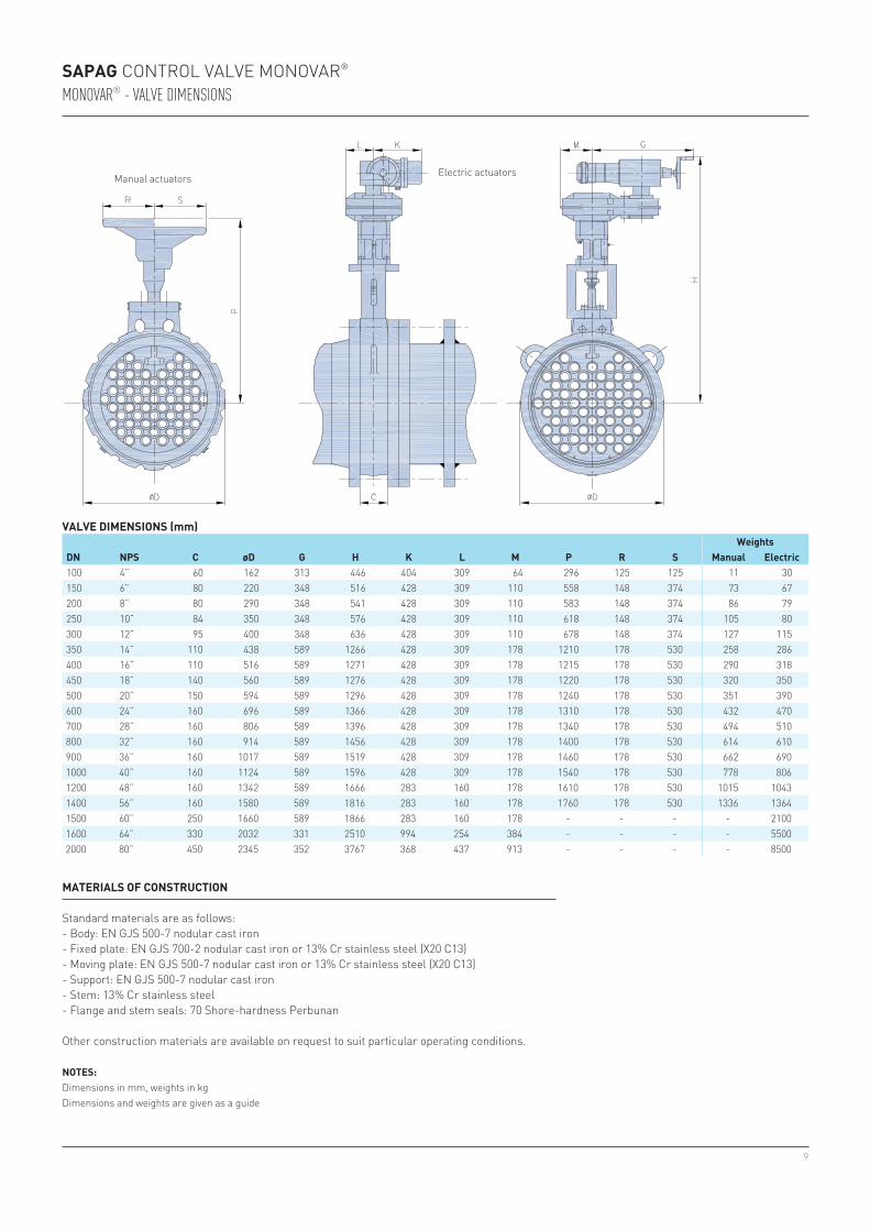
100 4” 60 162 313 446 404 309 64 296 125 125 11 30150 6” 80 220 348 516 428 309 110 558 148 374 73 67200 8” 80 290 348 541 428 309 110 583 148 374 86 79250 10” 84 350 348 576 428 309 110 618 148 374 105 80300 12” 95 400 348 636 428 309 110 678 148 374 127 115350 14” 110 438 589 1266 428 309 178 1210 178 530 258 286400 16” 110 516 589 1271 428 309 178 1215 178 530 290 318450 18” 140 560 589 1276 428 309 178 1220 178 530 320 350500 20” 150 594 589 1296 428 309 178 1240 178 530 351 390600 24” 160 696 589 1366 428 309 178 1310 178 530 432 470700 28” 160 806 589 1396 428 309 178 1340 178 530 494 510800 32” 160 914 589 1456 428 309 178 1400 178 530 614 610900 36” 160 1017 589 1519 428 309 178 1460 178 530 662 6901000 40” 160 1124 589 1596 428 309 178 1540 178 530 778 8061200 48” 160 1342 589 1666 283 160 178 1610 178 530 1015 10431400 56” 160 1580 589 1816 283 160 178 1760 178 530 1336 13641500 60” 250 1660 589 1866 283 160 178 - - - - 21001600 64” 330 2032 331 2510 994 254 384 - - - - 55002000 80” 450 2345 352 3767 368 437 913 - - - - 8500
Sapag CONTROL VALVE MONOVAR®
MONOVAR® - VAlVe diMeNsiONs
ValVe dimenSionS (mm)weights
dn npS c ød g h K l m p r S manual electric
Manual actuators Electric actuators
noteS:Dimensions in mm, weights in kgDimensions and weights are given as a guide
materialS oF conStruction
Standard materials are as follows:- Body: EN gJS 500-7 nodular cast iron- Fixed plate: EN gJS 700-2 nodular cast iron or 13% Cr stainless steel (x20 C13)- Moving plate: EN gJS 500-7 nodular cast iron or 13% Cr stainless steel (x20 C13)- Support: EN gJS 500-7 nodular cast iron- Stem: 13% Cr stainless steel- Flange and stem seals: 70 Shore-hardness Perbunan
Other construction materials are available on request to suit particular operating conditions.
10
Sapag CONTROL VALVE MONOVAR®
ValVe actuatorS
MONOVAR® control valves may be controlled manually (handwheel with micrometer position indicator) or by electric, pneumatic or hydraulic powered actuators. Information on the large range of actuator possibilities is available on request.
general inStallation inStructionS
- Allow the MONOVAR® to be removed at a later stage (observe clearances, use sliding joints and unions, etc.).
- Install the pipeline, or use the appropriate fittings, so that the MONOVAR® does not have to withstand any abnormal loads, resulting from mechanical pipe stresses or from thermal expansions.
- Check that the pipe sections are in line, that the flanges are parallel, that any sliding flanges are working correctly and that the holes in mating flanges coincide.
- Depending on the kind of water carried, provide a screen, a filter or sludge trap upstream of the valve in order to prevent it from jamming or suffering any mechanical damage.
- Check that the valve is installed correctly with respect to the direction of fluid flow. An arrow on the body of the MONOVAR® shows the correct direction; this direction must be followed, in order to prevent failure.
- Before installing the MONOVAR®, clean it with a jet of compressed air. Ensure that the pipes are perfectly clean and especially that there is no material inside them likely to cause serious damage (lumps of rust, welding pearls, slag, etc.).
- Bear in mind that proper installation of the MONOVAR® is a precondition for satisfactory working of the valve.
- MONOVAR® valves may be mounted between pipe flanges with the help of tie-rods, which ensure correct alignment. They may also be mounted at the end of a pipe. To facilitate mounting and disassembly, the use of sliding flanges or sleeves are recommended.
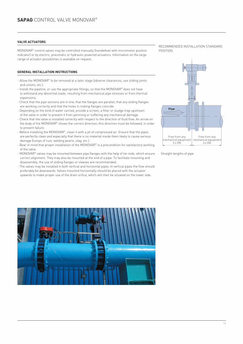
- The valves may be installed in both vertical and horizontal pipes. In vertical pipes the flow should preferably be downwards. Valves mounted horizontally should be placed with the actuator upwards to make proper use of the drain orifice, which will then be situated on the lower side.
RECOMMENDED INSTALLATION STANDARD POSITION
Flow
Free from any mechanical equipment
5 x DN
Free from any mechanical equipment
3 x DN
Straight lengths of pipe
11
Sapag CONTROL VALVE MONOVAR®
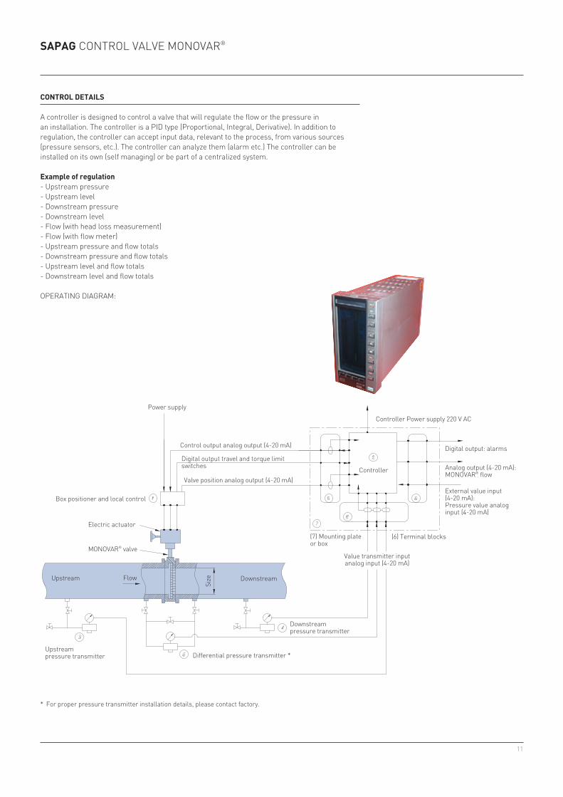
control detailS
A controller is designed to control a valve that will regulate the flow or the pressure in an installation. The controller is a PID type (Proportional, Integral, Derivative). In addition to regulation, the controller can accept input data, relevant to the process, from various sources (pressure sensors, etc.). The controller can analyze them (alarm etc.) The controller can be installed on its own (self managing) or be part of a centralized system.
example of regulation- Upstream pressure- Upstream level- Downstream pressure- Downstream level- Flow (with head loss measurement)- Flow (with flow meter)- Upstream pressure and flow totals- Downstream pressure and flow totals- Upstream level and flow totals- Downstream level and flow totals
OPERATINg DIAgRAM:
Power supply
Control output analog output (4-20 mA)
Digital output travel and torque limit switches
Valve position analog output (4-20 mA)
Box positioner and local control
Electric actuator
MONOVAR® valve
Upstream Flow
Size Downstream
Upstream pressure transmitter Differential pressure transmitter *
Downstream pressure transmitter
Controller Power supply 220 V AC
Controller
Value transmitter input analog input (4-20 mA)
Digital output: alarms
Analog output (4-20 mA): MONOVAR® flow
External value input (4-20 mA):Pressure value analog input (4-20 mA)
(6) Terminal blocks(7) Mounting plate or box
* For proper pressure transmitter installation details, please contact factory.

12
pentair ValVeS & controlSwww.pentair.com/valves
All Pentair trademarks and logos are owned by Pentair plc. All other brand or product names are trademarks or registered marks of their respective owners Because we are continuously improving our products and services, Pentair reserves the right to change product designs and specifications without notice. Pentair is an equal opportunity employer. © 2015 Pentair plc. All rights reserved.