Embed Size (px)
Citation preview
Computers and Structures, Inc.Berkeley, California, USA
Version 6.1September 1997
SAP2000
IntegratedFinite Elements Analysis
andDesign of Structures
TUTORIAL MANUAL

Copyright Computers and Structures, Inc., 1978-1997.The CSI Logo is a registered trademark of Computers and Structures, Inc.SAP2000 is a registered trademark of Computers and Structures, Inc.Windows is a registered trademark of Microsoft Corporation.
COPYRIGHT
The computer program SAP2000 and all associated documentation are proprietary andcopyrighted products. Worldwide rights of ownership rest with Computers andStructures, Inc. Unlicensed use of the program or reproduction of the documentation inany form, without prior written authorization from Computers and Structures, Inc., isexplicitly prohibited.
Further information and copies of this documentation may be obtained from:
Computers and Structures, Inc1995 University Avenue
Berkeley, California 94704 USA
tel: (510) 845-2177fax: (510) 845-4096
e-mail: [email protected]: www.csiberkeley.com

DISCLAIMER
CONSIDERABLE TIME, EFFORT AND EXPENSE HAVE GONE INTO THEDEVELOPMENT AND DOCUMENTATION OF SAP2000. THE PROGRAM HASBEEN THOROUGHLY TESTED AND USED. IN USING THE PROGRAM,HOWEVER, THE USER ACCEPTS AND UNDERSTANDS THAT NO WARRANTYIS EXPRESSED OR IMPLIED BY THE DEVELOPERS OR THE DISTRIBUTORSON THE ACCURACY OR THE RELIABILITY OF THE PROGRAM.
THE USER MUST EXPLICITLY UNDERSTAND THE ASSUMP-TIONS OF THEPROGRAM AND MUST INDEPENDENTLY VERIFY THE RESULTS.


i
Table Of Contents
Tutorial 1 2-D Frame with Static loading . . . . . . . . . . . . . . . . . . . . . . . . . 1
Tutorial 2 2-D Frame with Response Spectrum Loading . . . . . . . . . . . 11
Tutorial 3 2-D Frame with Time History Loading . . . . . . . . . . . . . . . . . . 17
Tutorial 4 2-D Frame Steel Design . . . . . . . . . . . . . . . . . . . . . . . . . . . . . . 27
Appendix A Toolbar Icon Descriptions . . . . . . . . . . . . . . . . . . . . A1


SAP2000 Tutorial Manual 1
T U T O R I A L 1
2-D Frame withStatic Loading
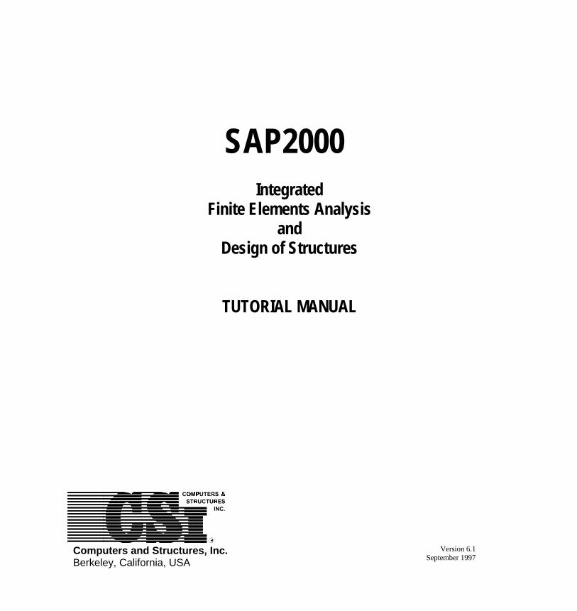
DescriptionThis tutorial describes the modeling and analysis of a seven-story two-dimensional framestructure, subjected to static earthquake loads. The framing and the static loads are shown inFigure 1-1.
Significant Features of Model and SAP2000• Using Templates
• Editing the model graphically
• Two-dimensional frame analysis
• Diaphragm constraints
• Lateral joint loads
• Vertical span loads
• Graphical output of results

Tutorial 1 2-D Frame with Static Loading
2 SAP2000 Tutorial Manual
257
257
257
211
211
176
176
GROUND
LEVEL 2
2.5K
5K
LEVEL 3
LEVEL 4
7.5K
12.5K
LEVEL 5
LEVEL 6
10K
LEVEL 7
15K
20K
ROOF
283
283
283
257
162
162
131
162
162
131
257
257
257
211
20K
257
211
211
131
104
104
131
104
104
104
20K 20K
104
20K
211
176
176
0.1K/ft
30’-0" 30"-0"
5 @ 13’0"
2 @ 13’-6"
10’10’ 10’ 10’ 10’ 10’
ALL COLUMNS ARE W14’SALL BEAMS ARE W24’SMEMBER WEIGHTS ARE INDICATEDTYPICAL STORY MASS = 0.49 kip-sec-sec/inMODULUS OF ELASTICITY = 29500 ksiSTEEL STRENGTH (f’y) = 36ksi
TYPICAL VERTICAL
EVERY LEVELLOADING
GLOBAL X
GLOBAL Z
Figure 1-1 Two-dimensional Frame Tutorial
Tutorial 1 2-D Frame with Static Loading
SAP2000 Tutorial Manual 3
Building the Model in SAP2000
Using Templates1. Select the units you want to work with from the status bar at the bottom of the SAP2000
window. In this case let’s start with Kip-ft.
Note: You can change the units you are working with at any time andSAP2000 will handle the conversion.
2. From the File menu select New Model from Template.
3. Select 2D Frame.
4. Fill in story and bay information. For now use 13 ft for story height and we will edit the firsttwo floors and their grids next.
Editing ModelWe are going to edit the framing and the grid at the same time.
1. From the Draw menu select Edit Grid.
Hint: Always try to locate your joints at grid intersections. By providinggrids you can make inputting, modifying and viewing of your modelmuch easier and faster.
2. Select the Z direction button to change the grids defining the story heights.
3. Select the Glue Joints to Grid Lines option. This will let you edit the joint locations andframing by simply editing the grid.
4. Edit the grid locations and press the OK button to close the form.
Hint: When you have finished editing the grid you can right click with themouse on the columns to find out if the columns are the properlength. This is a very practical way to inquire about any joint orframe member.

Tutorial 1 2-D Frame with Static Loading
4 SAP2000 Tutorial Manual
Editing SupportsThe next step is to change the supports on the structure from the default of pinned to fixed.
1. Select the Pointer Tool icon from the floating tool bar.
2. Draw a box completely around the three joints at the base of the structure
Hint: You can always look at the status bar to see what type of elementsand how many of them have been selected.
3. Select Assign Joint Restraints icon from the floating tool bar to set the fixed supports.You can also define other Joint properties including the restraint through the Assignmenu.
Assigning Member Sections1. Load all the frame sections that you will need for your model first. From the Define
menu select Frame Sections option. Then import the wide flanges shown in Figure1-1.
Note: You can select more than one section at a time in the SectionSelection list by using the ctrl key while you make the selections.
2. You will find under the Select menu item many ways to select joints and elements. Forthis problem you may find the Pointer/Window and the Intersecting Line select modeto be the most helpful.
3. Once you have selected the frame members you want, you can assign steel sections tothem through the Assign Frame Sections button on the floating tool bar.

Tutorial 1 2-D Frame with Static Loading
SAP2000 Tutorial Manual 5
Assigning Loads
Figure 1-2 Static Load Case Names Input Form
1. The first step in entering the loads is to define static load cases. From the Define menuselect Static Load Cases.
• DEAD can be used for the beam vertical loads and keep the Self Weight Multiplieras 1.
2. Define a static lateral load case called EQ for the earthquake load. Assign the lateral loadas a QUAKE type load. This will allow the load combinations for the design features ofthe program to be calculated automatically. Also set the Self Weight Multiplier to zero.
3. The vertical loads shown in Figure 1-1 can be assigned to the beams by selecting all thebeams and using the Assign Frame Span Loads button on the floating tool bar.
4. The static lateral loads need to be entered by selecting each node individually and usingthe Assign Joint Loads button.
Reminder: Make sure that you are adding the loads to the proper loadcase.
Setting Up Floor DiaphragmsSetting up floor diaphragms and specifying the floor mass in only the X direction are some commontechniques used to reduce the size of the problem solved by SAP2000. In addition, settingdiaphragms makes the structure behave more like a building with a rigid diaphragm.
1. Repeat these Steps for each floor:
• Select all the joints on a floor.

Tutorial 1 2-D Frame with Static Loading
6 SAP2000 Tutorial Manual
• From the Assign menu select Joint … Constraints.
• Select Add Diaphragm from the drop down list box.
♦ In the Diaphragm Constraint form give the diaphragm a name like DIA1 forthe first floor.
♦ Select Z-axis constraint. This defines a diaphragm perpendicular to the Z-axis.
♦ Press the OK button.
• Press the OK buttons to finish the operation.
• Repeat the steps for the other floors with a different diaphragm name for each one.
2. The Story masses are the same on all floors so select one node from each floor.
3. Change the input units to Kip-in since the Typical Story Mass provided in Figure 1-1 is givenin those units.
4. From the Assign menu select Joint … Masses
• Enter the story mass in the local direction 1 (which in this case is the global X)direction.
• All the other values are zero.
5. Change the units back to Kip-ft.
Material PropertiesThe final thing to check before running the analysis is the material properties.
1. From the Define menu select Materials.
2. In the Materials form select STEEL and press the MODIFY/SHOW MATERIAL button.
• In the Material Property Data form check that the material properties are correct.Remember that the values are reported in the current units.
Running AnalysisOnce data has been entered, it is time to run the model and take a look at our results.
1. Save your model.
2. Set the parameters for the analysis run by selecting from the Analyze menu Set Options.
• In the Analysis Options form select a Plane Frame analysis to reduce the size of thesolution and thus reduce the time needed for the analysis.
• Press the OK button to accept your changes.

Tutorial 1 2-D Frame with Static Loading
SAP2000 Tutorial Manual 7
3. Select Run from the Analyze menu to analyze the structure.
Note: Once the analysis has finished, you may want to look at the entireanalysis results screen before pressing the OK button. This is yourfirst check to see if there are any problems with the model.
Using the Results
Checking ResultsOnce you have run the model successfully you need to check and see that the output is correct andclose to what you expected.
Model checks:
1. Check that the base shear adds up to the total lateral load in the EQ load case.
• Select the bottom set of frame members and the nodes at the base of the structure.
• From the Assign menu select Group Names.
• Give the group a name like BASE SHEAR.
• Select the ADD NEW GROUP NAME button and press the OK button.
• From the Display menu select Show Group Joint Force Sums and select the groupname that you just assigned.
2. Look at the deflection and animate it for both lateral and vertical loads to make sure thatthe model is behaving as expected.
• From the Display menu select Show Deformed Shape and select the loading case inwhich you are interested. Also select the Wire Shadow option, so you can see theundeformed structural shape. See Figure 1-3 and Figure 1-4 for the deformed shapesof the structure. Right click on any joint to see its displacement and rotation.
• Animate the displayed load by pressing the START ANIMATION button at thebottom of the status bar (A window with the deformed shape will need to be activefor the button to show). You can also save the animation as an *.AVI file for laterviewing from the File menu. (See online help under “Export an AVI file”.)
Try This: Press the + and – buttons next to the Animate button and seewhat happens to the form with the deformed shape.
• Press the STOP ANIMATION button when you are finished looking at it.
If these checks show that the input information appears to be correct then we can move to the moreadvanced checks.

Tutorial 1 2-D Frame with Static Loading
8 SAP2000 Tutorial Manual
Figure 1-3 Static Deformed Shape Figure 1-4 Lateral Deformed Shape
Structural PerformanceYou will often want to make certain that the structure is within the performance limits, such asstresse ratio, set by the code being used. SAP2000 will do the stress checks automatically when amember is designed. (The design features of SAP2000 will be discussed in more detail insubsequent tutorials.)
1. The structural elements can be designed by simply selecting from the Design menu the StartDesign/Check of Structure option.
• The frame elements will now display colors showing their stress level with the stressratio level value indicated below the beam. A value of 1 is 100% stressed.
• Other design and input information can also be displayed by selecting from theDesign menu the Display Design Info option.
Tutorial 1 2-D Frame with Static Loading
SAP2000 Tutorial Manual 9
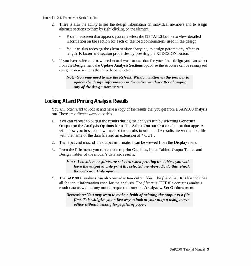
2. There is also the ability to see the design information on individual members and to assignalternate sections to them by right clicking on the element.
• From the screen that appears you can select the DETAILS button to view detailedinformation on the section for each of the load combinations used in the design.
• You can also redesign the element after changing its design parameters, effectivelength, K factor and section properties by pressing the REDESIGN button.
3. If you have selected a new section and want to use that for your final design you can selectfrom the Design menu the Update Analysis Sections option so the structure can be reanalyzedusing the new sections that have been selected.
Note: You may need to use the Refresh Window button on the tool bar toupdate the design information in the active window after changingany of the design parameters.
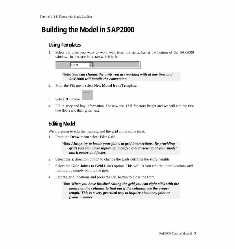
Looking At and Printing Analysis ResultsYou will often want to look at and have a copy of the results that you get from a SAP2000 analysisrun. There are different ways to do this.
1. You can choose to output the results during the analysis run by selecting GenerateOutput on the Analysis Options form. The Select Output Options button that appearswill allow you to select how much of the results to output. The results are written to a filewith the name of the data file and an extension of *.OUT .
2. The input and most of the output information can be viewed from the Display menu.
3. From the File menu you can choose to print Graphics, Input Tables, Output Tables andDesign Tables of the model’s data and results.
Hint: If members or joints are selected when printing the tables, you willhave the output to only print the selected members. To do this, checkthe Selection Only option.
4. The SAP2000 analysis run also provides two output files. The filename.EKO file includesall the input information used for the analysis. The filename.OUT file contains analysisresult data as well as any output requested from the Analyze …Set Options menu.
Remember: You may want to make a habit of printing the output to a filefirst. This will give you a fast way to look at your output using a texteditor without wasting large piles of paper.
Tutorial 1 2-D Frame with Static Loading
10 SAP2000 Tutorial Manual
Final CommentsAs you can see, SAP2000 is a powerful structural analysis tool and can be used for a variety ofproblems. However it is very important to understand the engineering principles on which it isbased.
Most projects start as feasibility exercises and mature into a full analysis/design project. This makesit very important to decide early on what the proper tool is so there will be no need to changeprograms during the middle of a project. SAP2000 tries to address as many of the needs that adesigner may have during the life of the project.
Features that help in the design process include:
• The ability to design small and large projects without having to learn a new program.
• The ability to design steel and concrete members within the same program.
• Fast analysis algorithms allowing time for developing the model and optimizing thedesign of structural elements.
• The ability to easily modify and improve the design.
There are probably as many ways to model a structure as there are engineers. However, you mayfind some of these ideas helpful:
• Start with a basic model of your structure and try and understand it before adding moredetail. It is always easier to fix structural system related problems while the model is stillsimple.
• Ensure the structure can be constructed and will behave the way you have modeled it. Ifit can not be built in such a way, you may need to understand what effect that will haveon the structure.
• Thoroughly document your design including assumptions, areas that need to bereviewed and information that is still required. You can use the User Comments andSession Log text editor under the File menu. This basic text editor is built into theprogram allowing your notes to be with your model.
• Experiment with alternative structural systems. SAP2000 was designed to be fast; usethe extra time to improve your design.
• If there is time to do it properly later there should be time to do it properly from the start.

SAP2000 Tutorial Manual 11
T U T O R I A L 2
2-D Frame withResponse Spectrum Loading
DescriptionThis tutorial is a continuation of Tutorial 1. In this tutorial we will demonstrate how to add aResponse Spectrum analysis to the 2-d frame. The basis for the Response Spectrum will be theUBC94S2 spectrum, which is included in SAP2000.
Significant Features of Model and SAP2000• Using Help to get instructions on SAP2000 features
• Adding a Response Spectrum load case
• Scaling the Response Spectrum for use in design

Tutorial 2 2-D Frame with Response Spectrum Loading
12 SAP2000 Tutorial Manual
Defining Response SpectrumA Response Spectrum is the maximum response of a system excited at its base by a timeacceleration function. It is expressed in terms of the natural frequency and the amount of damping ofthe system. The UBC94S2 Response Spectrum function that we are going to use is provided withSAP2000 and so it will not need to be defined separately. If there were a need to define your ownResponse Spectrum Function you could use the online help to get step-by-step instructions.
Online Help
Remember: You can use the following methods to get information on anySAP2000’s functions.
1. From the Help menu select Search for Help on.
2. With the Index tab selected:
• In Area 1 type ‘Define’. You will then see in the Area 2 a list of all the help topicsthat start with define. One of those topics is Define Response Spectrum Functions,which is the topic we need help on. Double click on the line with the words ‘DefineResponse Spectrum Functions’ to show the help information on that topic.
3. Alternately, select the Find tab to search for key words in any of the online help topics.
• If this is the first time that you use Find for the SAP2000 online help, a Find SetupWizard form will appear.
♦ Press the NEXT button to accept the criteria for building the find database.
♦ Press the FINISH button to have the database built.
• In Area 1 type ‘Response Spectrum’
• In Area 3 you will again find ‘Define Response Spectrum Functions’ which you canselect to get to the help information.
Note: You can find more information on using online help, in yourwindows documentation. You can also run the WINHELP32.HLPfile in your C:\WINDOWS\HELP folder.
Defining Response Spectrum Case
1. If the model is locked then use the Lock/Unlock Model button to unlock it so you canmake changes to the model.
2. Set the units to Kip-ft.
3. From the Define menu select Response Spectrum Case.
4. Press the ADD NEW SPECTRA button on the Response Spectra form.
5. In the Response Spectrum Case Data form:

Tutorial 2 2-D Frame with Response Spectrum Loading
SAP2000 Tutorial Manual 13
• Input a Damping of 0.05 (5 %)
• Select the UBC94S2 for the U1 direction and a Scale Factor of 32.2 ft/sec2. Thescale factor is used for the Response Spectrum because UBC94S2 is normalized bythe acceleration due to gravity g.
• The remainder of the default values are acceptable.
• Press the OK buttons to accept the changes you have made to both forms.
Running AnalysisOnce you have made the modifications, it is time to run the model and take a look at the ResponseSpectrum results.
1. Save your model.
2. Set the parameters for the analysis by selecting from the Analyze menu Set Options.
• Select the Dynamic Analysis check box.
• Press the SET DYNAMIC PARAMETERS button and change the Number ofModes used in the solution to 7. The remaining default values are acceptable.
• Press the OK button on both forms to accept your changes.
Note: You have to decide how many modes you will need to consider inyour analysis to make the results meaningful. There are manycriteria to take into account, but for a structure as simple as ours youcan consider the same number of modes as there are floors.
3. Select Run Minimized from the Analyze menu to analyze the structure.
Note: The Run Minimized option is extremely helpful when running largemodels that may take a lot of time to analyze. This option allowsSAP2000 to run in the background so you can continue working onother programs. The other advantage to this option is that you get acancel button that allows you to cancel a run if you need to.
Checking Results1. Check the modal shapes and periods to see that they are as expected.
• From the Display menu select Show Mode Shape and select the mode you areinterested in. You may also want to select the Wire Shadow option so you can seewhat the undeformed shape looks like. See Figures 2-1 through 2-4 and note that themode number and period is shown as the title of the window.

Tutorial 2 2-D Frame with Response Spectrum Loading
14 SAP2000 Tutorial Manual
Note: You can look at subsequent mode shapes by pressing the + and –buttons that are next to the START ANIMATION button.
2. It is helpful to see the base shear produced due to the Response Spectrum analysis.
• Using the BASE SHEAR group that was set up in Tutorial 1, look at the base shearfor the structure due to the Response Spectrum. You will see that it is substantiallylarger than the static load case.
3. You can also check the displacement of a joint due to the Response Spectrum.
• From the Display menu select Show Deformed Shape.
♦ In the Deformed Shape form select the load case for the spectral analysis.
♦ Press the OK button.
• Right click on a joint at the top level of the structure to see the displacement of thejoint in the global X direction.
4. Check the mass participation to see if enough modes were included in the solution. Thiswill need to be done outside of SAP2000 by looking at the filename.OUT file using a texteditor like WordPad.
• Minimize the SAP2000 program.
• Start WordPad or another text editor.
• In WordPad open the file filename.OUT. Where filename is the name of the file youused when saving this tutorial.
♦ Find the section titled MODAL PARTICIPATING MASS RATIOS as shown inFigure 2-5.
♦ You will find under the CUMULATIVE SUM column that Mode 1 throughMode 7 includes 100% of the mass participation. Which means that the 7 modesincluded in the analysis were enough.

Tutorial 2 2-D Frame with Response Spectrum Loading
SAP2000 Tutorial Manual 15
Figure 2-1 Mode 1 Shape and Period Figure 2-2 Mode 2 Shape and Period
Figure 2-3 Mode 3 Shape and Period Figure 2-4 Mode 4 Shape and Period

Tutorial 2 2-D Frame with Response Spectrum Loading
16 SAP2000 Tutorial Manual
Figure 2-5 Output File Block for Mass Participation
Scaling Response SpectraSome design codes allow you to scale the spectral analysis base shear to the static base shear. So inthis case to get the new scale factor for the Response Spectra you would:
1. Divide the Static Base Shear by the Spectral Base Shear and multiply that number by32.2 ft/sec2 to get a new scale factor for the Response Spectrum.
2. Substitute the new scale factor for the Response Spectra Case.
3. Rerun the analysis to get the new member forces due to the scaled Response Spectrum.
Final CommentsA Response Spectra analysis introduces another level of complexity, which requires the engineer tofurther check the analysis results and the assumptions used in the modeling. Things to keep in mindduring a Response Spectrum analysis:
• Completely understand the static behavior of the model before running a dynamicanalysis.
• You will need to completely understand the rationale and applicability of scalingdynamic analysis results to equivalent static base shear before scaling results for anygiven model.
• The speed advantages of running a Response Spectrum analysis over a full Time Historyanalysis can be substantial. In design, the Response Spectrum analysis can provide aneven greater speed advantage, due to the fact that the design check does not need to bedone at each time segment. However, one needs to be aware of the limitations of thismethod over a full Time History analysis.
SAP2000 Tutorial Manual 17
T U T O R I A L 3
2-D Frame withTime History Loading
DescriptionThis tutorial builds on Tutorials 1 and 2 by adding an earthquake load specified as a baseacceleration time history. The earthquake excitation is shown in Figure 3-1. It is the N-Scomponent of the 1940 El Centro earthquake. The results of the Time History are used togenerate a Response Spectrum which in turn is used to reanalyze the structure as acomparison.
Significant Features of Model and SAP2000• Time History response to base excitation
• Plotting time history results
• Plotting a Response Spectrum from a Time History
• Importing a Response Spectrum to use for analysis
Tutorial 3 2-D Frame with Time History Loading
18 SAP2000 Tutorial Manual
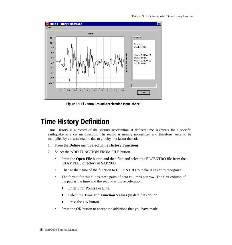
Figure 3-1 El Centro Ground Acceleration Input - ft/sec2
Time History DefinitionTime History is a record of the ground acceleration at defined time segments for a specificearthquake in a certain direction. The record is usually normalized and therefore needs to bemultiplied by the acceleration due to gravity or a factor thereof.
1. From the Define menu select Time History Functions.
2. Select the ADD FUNCTION FROM FILE button.
• Press the Open File button and then find and select the ELCENTRO file from theEXAMPLES directory in SAP2000.
• Change the name of the function to ELCENTRO to make it easier to recognize.
• The format for this file is three pairs of data columns per row. The first column ofthe pair is the time and the second is the acceleration.
♦ Enter 3 for Points Per Line.
♦ Select the Time and Function Values (in data file) option.
♦ Press the OK button.
• Press the OK button to accept the additions that you have made.
Tutorial 3 2-D Frame with Time History Loading
SAP2000 Tutorial Manual 19
3. From the Define menu select Time History Cases to define the specifics of the TimeHistory for your model.
• Select the ADD NEW HISTORY button.
• Press the MODIFY/SHOW MODAL DAMPING button and enter 0.05 (5%) for allmodes and hit the OK button.
• Enter 500 in Number of Output Time Steps.
• Enter 0.02 (sec) in Output Time Step Sizes. This will give us 10 seconds of theearthquake time history.
• Select Linear from the Analysis Type drop down list box.
• In the Load Assignment area:
♦ select ACC DIR1 under Load
♦ select ELCENTRO under Function
♦ Set the Scale Function to the acceleration due to gravity which is 386.4 in/sec2
if your units are in Kip-in and 32.2 ft/sec2 if your units are in Kip-ft.
♦ Set the Arrival Time and Angle to Zero.
♦ Press the ADD button to add the load assignments and the OK button to acceptthe data you just entered.
• Press the OK button on both forms to accept your additions.
We have now entered all the information we need for a Time History analysis.
Note: It is usually a good idea to run your model every time you make amajor change or addition. This will give you a way to catch yourmistakes early and save you time in your final design.
Running Analysis1. Save your model.
2. Set the parameters for the design run by selecting from the Analyze menu Set Options.
• Check that the Dynamic Analysis settings are the same as for Tutorial 2.
3. Select Run from the Analyze menu to analyze the structure.

Tutorial 3 2-D Frame with Time History Loading
20 SAP2000 Tutorial Manual
Using the Results
Checking ResultsOnce you have run the model successfully you need to check and see that the output is correct andclose to what you expected.
1. Check the base shear produced due to the time history analysis.
• From the Display menu select the Show Time History Traces option.
♦ From the Time History Display Definition form press the DEFINEFUNCTIONS button.
♦ In the Time History Functions form select Add Base Functions and check onlythe Base Shear X option.
♦ Press the OK buttons to get back to the Time History Display Definition form.
♦ Add the Base Shear X function to the Plot Functions list box.
♦ Then press the DISPLAY button to see the plot of the base shear in the global Xdirection as a function of time. See Figure 3-2.
Note: You can also view the Time History plot of the base shear byselecting Add Group Summation Forces instead of Add BaseFunctions and selecting the base shear group that was defined inTutorial 1.
2. You can also check the displacement of a joint due to the time history.
• Select a joint and from the Display menu choose the Show Time History Tracesoption.
♦ Press the DEFINE FUNCTIONS button and in the Time History Functionsform select the joint name from the list and press the MODIFY/SHOW THFUNCTION button.
♦ In the Time History Joint Function form select the DISPL Vector Type and UXVector Direction.
♦ Press the OK button to accept the changes.
♦ Press the OK buttons to go back to the Time History Display Definition form.
♦ Add the joint from the List of Functions to the Plot Functions list box andremove the Base Shear X function.
♦ Press the DISPLAY button to see the joint displacement with respect to time.See Figure 3-3.

Tutorial 3 2-D Frame with Time History Loading
SAP2000 Tutorial Manual 21
• You can also define a joint function directly in the Time History Display Definitionform without selecting it first.
♦ In the Time History Display Definition form press the DEFINE FUNCTIONSbutton and in the Time History Functions form select Add Joint Disps/Forces.
♦ In the Time History Joint Function form enter the Joint ID.
♦ Select the Vector Type and Vector Direction.
♦ Press the OK buttons to go back to the Time History Display Definition formwhere you will find the new joint function in the List of Functions list box.
Figure 3-2 Base Shear - Kips
Tutorial 3 2-D Frame with Time History Loading
22 SAP2000 Tutorial Manual
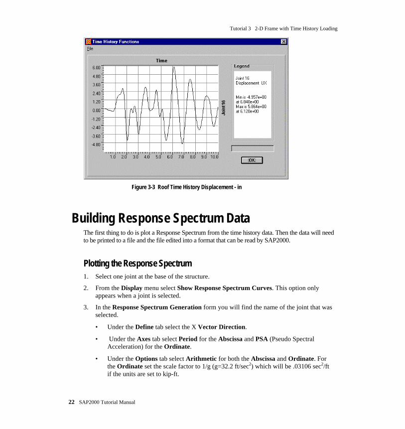
Figure 3-3 Roof Time History Displacement - in
Building Response Spectrum DataThe first thing to do is plot a Response Spectrum from the time history data. Then the data will needto be printed to a file and the file edited into a format that can be read by SAP2000.
Plotting the Response Spectrum1. Select one joint at the base of the structure.
2. From the Display menu select Show Response Spectrum Curves. This option onlyappears when a joint is selected.
3. In the Response Spectrum Generation form you will find the name of the joint that wasselected.
• Under the Define tab select the X Vector Direction.
• Under the Axes tab select Period for the Abscissa and PSA (Pseudo SpectralAcceleration) for the Ordinate.
• Under the Options tab select Arithmetic for both the Abscissa and Ordinate. Forthe Ordinate set the scale factor to 1/g (g=32.2 ft/sec2) which will be .03106 sec2/ftif the units are set to kip-ft.

Tutorial 3 2-D Frame with Time History Loading
SAP2000 Tutorial Manual 23
Note: The scale factor is used to normalize the Response Spectra. TheTime History that is being used to produce the Response Spectra hasbeen scaled by g so we need to divide by the same number to get backto normalized values.
• Under the Period tab select the Default and Structural frequencies, which are usedin the generation of Response Spectrum. Default frequencies are a set of built-infrequencies, typically of interest in structures. Structural frequencies are thestructure’s natural frequencies.
• Under the Damping tab keep only the .05 Damping Value. As the structure isassumed to have 5% damping, we will not need any other values.
• Press the DISPLAY button when you finish.
4. You will see a plot of a response spectrum for the El Centro earthquake at 5% damping.See Figure 3-4.
Figure 3-4 Response Spectrum from Time History
5. In the Response Spectrum Curves form select from the File menu the Print Tables toFile option. This will make a file that has two columns. The first one is the Period and thesecond is the PSA for each period.
• Save the file under the name RS-ELCEN.TXT

Tutorial 3 2-D Frame with Time History Loading
24 SAP2000 Tutorial Manual
Editing TableThe next step is to do some minor editing on the RS-ELCEN.TXT text file so it is in a format thatSAP2000 can read. When the file is made, there is some extraneous information that is added tohelp you understand the content of the file. This extra information needs to be deleted.
1. Open RS-ELCEN.TXT in a text editor like WORDPAD or NOTEPAD.
• Select all the text that is shown highlighted in Figure 3-5 and delete it.
• Save RS-ELCEN.TXT as a text file using the same name.
2. Now that the file only has the Period and the PSA columns, it is in a format that SAP2000 canread.
Figure 3-5 Text File of Response Spectrum Table
Reading Spectral DataNow that we have the data in a format that can be read by SAP2000 we simply need to tell theprogram where the file is and how it is set up.
1. If the model is locked press the Lock/ Unlock Model button on the toolbar. This will unlockthe model and allow you to make modifications to it.
2. From the Define menu select Response Spectrum Functions.

Tutorial 3 2-D Frame with Time History Loading
SAP2000 Tutorial Manual 25
3. In the Response Spectrum Functions form press the Add Function from File button.
• Name the spectra RSELCEN
• Press the Open File button and pick the RS-ELCEN.TXT file from the Pick Fileform.
• Keep the Number Of Points Per Line to 1 as there is only one set of response dataon each line.
• Select the Period and Acceleration Values option.
• Press the OK buttons to close the forms.
4. From the Define menu select Response Spectrum Cases.
5. In the Response Spectrum form press the ADD NEW SPECTRA button.
• Set the Modal Damping to 0.05.
• In the Input Response Spectra area select RSELCEN for the U1 direction and giveit a scale factor of 32.2 ft/sec2.
• The remaining default values are acceptable.
• Press the OK buttons to close the forms.
Running AnalysisOnce you have made the modifications, it is time to run the model and take a look at our results.
1. Save your model.
2. Select Run Minimized from the Analyze menu to analyze the structure.

Tutorial 3 2-D Frame with Time History Loading
26 SAP2000 Tutorial Manual
Checking ResultsThe first thing to do is check the maximum deflection at the top of the structure and the base sheardue to the Time History and the Response Spectrum. This will show how well the outlined methodworks. At the end of this section you will find the results of the static lateral load, ResponseSpectrum and Time History analysis.
Response Spectrum Deflection
1. From the Display menu select Display Deformed Shape.
• In the Deformed Shape form select the load case for the spectral analysis.
• Press the OK button.
2. Right click on a joint at the top level of the structure to see the displacement of the jointin the global X direction.
Response Spectrum Base Shear
Using the BASE SHEAR group that was set up in Tutorial 1, look at the base shear for the structuredue to the Response Spectrum.
Time History Deflection and Base Shear
1. Using the method outlined in the first part of this tutorial, plot the deflection at the top of thestructure.
2. Now remove the joint from the Plot Functions list and plot the Base Shear X direction byselecting it from the List of Functions in the Time History Display Definitions form.
Static Lateral Response Spectrum Time History
Max Deflection 1.6 in 5.5 in 5.9 in
Max Base Shear 72.5 Kips 306 Kips 286 Kips
Table 3-1 Comparison of Lateral Load Results
Final CommentsAs you have seen the Time History analysis is much more time consuming than a ResponseSpectrum analysis. The Response Spectrum and Time History analysis results can give similarresults. However it is very important for the engineer to understand the strengths and limitations ofeach method so they can be effectively used.

SAP2000 Tutorial Manual 27
T U T O R I A L 4
2-D Frame Steel Design
DescriptionThis tutorial is provided to highlight the powerful tools in SAP2000 for designing the structure afterit has been analyzed. The steel design features will be looked at in this tutorial to design the structurethat was modeled in Tutorial 1.
Significant Features of Model and SAP2000• Assigning member rigid End Offsets
• Automatic selection groups
• Changing member properties
• Designing members by groups
• Including P-Delta effects in analysis
• Viewing design results
• Overriding Auto Selection sections

Tutorial 4 2-D Frame Steel Design
28 SAP2000 Tutorial Manual
COLUMN
GROUND
LEVEL 2
2.5K
5K
LEVEL 3
LEVEL 4
7.5K
12.5K
LEVEL 5
LEVEL 6
10K
LEVEL 7
15K
20K
ROOF
20K
COLUMN
BEAM BEAM
20K 20K 20K
COLUMN
0.1K/ft
30’-0" 30"-0"
5 @ 13’0"
2 @ 13’-6"
10’10’ 10’ 10’ 10’ 10’
ALL COLUMNS ARE W14’SALL BEAMS ARE W24’STYPICAL STORY MASS = 0.49 kip-sec-sec/inMODULUS OF ELASTICITY = 29500 ksiSTEEL STRENGTH (f’y) = 36ksi
GLOBAL X
GLOBAL Z
COLUMN COLUMN COLUMN
COLUMN COLUMN COLUMN
COLUMN COLUMN COLUMN
COLUMN COLUMN COLUMN
COLUMN COLUMN COLUMN
COLUMN COLUMN COLUMN
BEAM BEAM
BEAM BEAM
BEAM BEAM
BEAM BEAM
BEAM BEAM
BEAM BEAM
Figure 4-1 Two-dimensional Frame Tutorial

Tutorial 4 2-D Frame Steel Design
SAP2000 Tutorial Manual 29
Building the SAP2000 ModelYou will be able to use the file you developed in Tutorial 1 with a few modifications.
MaterialsFirst thing to do is set the material properties.
1. Check that the units are set to Kip-in.
2. From the Define menu select Materials.
3. Select the STEEL Material type and press the MODIFY/SHOW MATERIAL button.
4. Set the Steel Yield Stress fy to 36 Ksi.
5. Set Modulus of Elasticity E to 29,500 Ksi.
6. Press the OK buttons to accept the changes and close the forms.
Loads1. In Tutorial 1 you assigned a set of point and uniform loads as DEAD load and included the
member self weight. (See Figure 4-2 for the new Static Loads Case list.) In this tutorial wewill assign a load case for the live load and one for the self weight of the members. Including aload case for the self weight of the structure is a good way to keep track of the structural weightfor design optimization purposes. The loads are separated into dead, live and lateral earthquakeload cases so the design part of SAP2000 can automatically generate load combinations.
• For the DEAD load case set the Self Weight Multiplier to 0.
• Add a load case SELF of Type DEAD for the member self weight and set SelfWeight Multiplier to 1.
• Add another static load case named LIVE and assign it as Type LIVE.
2. Add the same loads that are in the DEAD load case to the LIVE load case. This will mean thateach beam in the structure has identical dead and live loads. (See Tutorial 1 for instructions onentering loads.)

Tutorial 4 2-D Frame Steel Design
30 SAP2000 Tutorial Manual
Figure 4-2 Static Load Cases
Defining an Auto Selection GroupThe Auto Selection feature in SAP2000 is a very effective way to design structures. By defining aset of steel sections as an Auto Selection section group, the program can design each frame elementusing only the sections in that group. For example we can define an Auto Selection group calledCOLUMN with only W14 sections and a BEAM group with only W24 sections. In this way framemembers assigned a COLUMN Auto Selection section will only be designed using W14 sections.
The first thing to do is define an Auto Selection group, which only includes column sections.Essentially what we are doing is giving the program a list of sections which it can choose fromwhen designing the frame members. In turn the program will select the most efficient section out ofthat group.
Once the preliminary design is done and it is time to start fine tuning the design, the BEAM andCOLUMN groups can be replaced by the optimum sections from those Auto Selection groups. Thiswill then assign a specific section for both the analysis and design, which will make it much easierto change the few sections that may need to be modified.
Note: Auto Selection only works for steel frame sections.
1. From the Define menu select Frame Sections.
2. In the Frame Sections form import all the steel sections between W14x61 and W14x283.
• Select IMPORT I/WIDE FLANGE from the Import drop down list box.
• In the sections form scroll down and select W14x283.
• With the SHIFT button pressed left click on W14x61 and press the OK button. Thiswill select these sections and all the sections in between.
3. In the Frame Sections form delete any duplicate sections.

Tutorial 4 2-D Frame Steel Design
SAP2000 Tutorial Manual 31
Remember: You will not be able to delete a section that is in use. Thisfeature is a way for the program to insure that all the members areassigned to existing sections.
4. From the Frame Section form add an Auto Select section which will be at the bottom ofthe Add drop down list box.
• Change the Auto Section Name to COLUMN.
• In the Auto Selections list box select and remove using the Remove button all thesections except the W14’s. This will mean that any frame member assigned aCOLUMN section will be designed from the list of W14 sections in the AutoSelections list box. (See Figure 4-3.)
Figure 4-3 Defining the COLUMN Auto Selection group
5. Using the instructions outlined in steps 2 through 4:
• Import all the sections between W24x55 and W24x162.
• Assign an Auto Selection group called BEAM with only the W24 sections in it.
6. Finally, select all the vertical frame members and assign the COLUMN section to them.Then select all the horizontal frame members and assign the BEAM section to them. (SeeTutorial 1 for instructions on assigning sections to frame members.)
Note: You can of course select a specific section for both the analysis anddesign instead of using an Auto Select section . You simply need toassign the frame member a steel section and design it as outlined inTutorial 1. The steel section can either be a user-defined section or asection from the Section Property file.

Tutorial 4 2-D Frame Steel Design
32 SAP2000 Tutorial Manual
Running AnalysisOnce data has been entered, it is time to run the model and take a look at our results.
1. Save your model.
2. Set the parameters for the design run by selecting from the Analyze menu Set Options.
• In the Analysis Options form select a Plane Frame analysis to reduce the size of thesolution and thus reduce the time needed for the analysis.
• Select the Include P-Delta check box.
• Press the SET P-DELTA PARAMETERS button to set the analysis parameters.
♦ Set Maximum Iterations to 10.
♦ Include the two dead load cases DEAD and SELF in the P-Delta loadcombination with a factor of 1.
♦ Include the LIVE load case with a factor of 1.
Note: The load factors that you use need to be the load factor for thedesign load combo that includes lateral loads and has the largestvertical load on the structure.
♦ The remaining default values are acceptable.
♦ Press the OK buttons to accept the changes and close the forms.
3. Select from the Analyze menu the Run option to analyze the structure.
Note: Because we have assigned groups of sections and not specificsections for our design, SAP2000 will take suitable section propertiesto calculate the stiffness matrix and any other properties it may need.Once the first analysis and design has been performed, the programcan be instructed to use the designed sections for analysis.
Designing SectionsOnce you have run the analysis and checked the analysis results, you can set the parameters neededfor steel design.
Selecting CodeThe information in the analysis run is used to do a code check on the frame elements.
1. From the Options menu select Preferences.

Tutorial 4 2-D Frame Steel Design
SAP2000 Tutorial Manual 33
2. In the Preferences form under the Steel tab, select the steel code you want to use. In thiscase let’s use AISC-ASD-89.
• Use the same Section Properties file that was used for importing the steel sections.
Load Combinations and Design
Figure 4-4 Design Menu Options
Once you have selected the code you will be using to design the members, you need to check theload combinations that will be used for the design.
1. The first thing to do is make sure that under the Design menu the Steel Design item has acheck mark on it. This will tell SAP2000 to design the steel sections.
2. From the Design menu choose Select Design Combos.
• Look at the automatically created combos in the Design Combos list box byselecting the combo and pressing the SHOW button.
• If you find that there are other load combos that you want to use in your design, youcan add them. Simply define the combo from the Define menu and then in the SelectDesign Combos form add the combo to the Design Combos list.
3. Run the Design/Check from the Design menu by selecting Start Design/Check of Structure.
• Each of the elements will be designed with the most efficient section from its AutoSelection section group.
• SAP2000 will automatically display on the active window the percent of maximumstress below each of the elements.
• The elements will also be color coded for convenience with a stress ratio color keylocated at the bottom of the window.

Tutorial 4 2-D Frame Steel Design
34 SAP2000 Tutorial Manual
Note: If you just want to check the design for a limited number of framemembers, you can select those members and then choose StartDesign/Check of Structure.
Viewing Results and RedesigningThe first thing to do when a Design/Check is performed, is to see that the results are correct.SAP2000 gives the user some tools to check the results.
1. Right click on any member to view its design results. The element you have selected willbe flashing to identify itself.
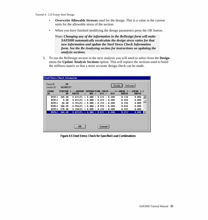
2. In the Steel Stress Check Information form, you will find a list of the loadcombinations used to check the section at various locations along the members. (SeeFigure 4-5)
• One of the combos will be highlighted when you first see the form. That is thecontrolling combo that was used to design the section.
• Next to each combo there is the location along the member where the check wasperformed followed by the stress ratio for moment interaction and shear.
Hint: You can change the number of locations at which the forces arereported. Select the frame elements and choose from the Assign menuFrame …Output Segments and change the number of segments. Youwill then need to rerun the analysis to get the result for the newsegments.
3. Selecting any of the combo checks and pressing the Details button will show the analysisresults for that member and governing equation from the code. (See Figure 4-6)
4. Pressing the ReDesign button will bring up the Element Overwrite Assignments form.In this form you can:
Note: If you make any changes in the Element Overwrite Assignmentsform through the ReDesign button, you will need to press the RefreshWindow button on the tool bar to see the updated design results onthe current window .
• Select another section to see the effects of the change on the stress ratios.
Note: In the Auto Selection mode, this section can be used in developing anew stiffness matrix if you “Update Analysis Sections”. However,Auto Selection will still take place the next time you run the designcheck.
• Set the member as a Moment Resisting Element or a Brace.
• Overwrite design factors like the effective length, unbraced length ratio and so on.
Tutorial 4 2-D Frame Steel Design
SAP2000 Tutorial Manual 35
• Overwrite Allowable Stresses used for the design. This is a value in the currentunits for the allowable stress of the section.
• When you have finished modifying the design parameters press the OK button.
Note: Changing any of the information in the ReDesign form will makeSAP2000 automatically recalculate the design stress ratios for thatnew information and update the Steel Stress Check Informationform. See the Re-Analyzing section for instructions on updating theanalysis sections.
5. To use the ReDesign section in the next analysis you will need to select from the Designmenu the Update Analysis Sections option. This will replace the sections used to buildthe stiffness matrix so that a more accurate design check can be made.
Figure 4-5 Steel Stress Check for Specified Load Combinations

Tutorial 4 2-D Frame Steel Design
36 SAP2000 Tutorial Manual
Figure 4-6 Detailed Steel Design Info of a Beam Element
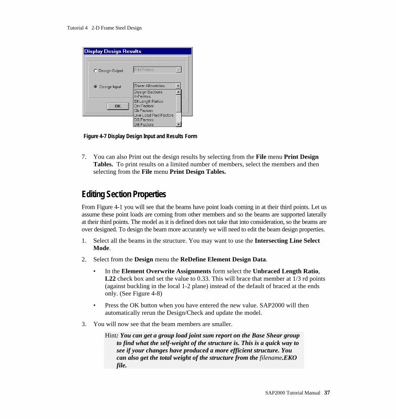
6. You can also look at various design results on the graphics screen by selecting from theDesign menu the Display Design Info option. These results will be plotted on the bottomand to the right of frame members.
Note: The sections used for the analysis are shown at the top and to theleft of the frame members. All the design information is shown at thebottom and to the right of the frame members.
Tutorial 4 2-D Frame Steel Design
SAP2000 Tutorial Manual 37
Figure 4-7 Display Design Input and Results Form
7. You can also Print out the design results by selecting from the File menu Print DesignTables. To print results on a limited number of members, select the members and thenselecting from the File menu Print Design Tables.
Editing Section PropertiesFrom Figure 4-1 you will see that the beams have point loads coming in at their third points. Let usassume these point loads are coming from other members and so the beams are supported laterallyat their third points. The model as it is defined does not take that into consideration, so the beams areover designed. To design the beam more accurately we will need to edit the beam design properties.
1. Select all the beams in the structure. You may want to use the Intersecting Line SelectMode.
2. Select from the Design menu the ReDefine Element Design Data.
• In the Element Overwrite Assignments form select the Unbraced Length Ratio,L22 check box and set the value to 0.33. This will brace that member at 1/3 rd points(against buckling in the local 1-2 plane) instead of the default of braced at the endsonly. (See Figure 4-8)
• Press the OK button when you have entered the new value. SAP2000 will thenautomatically rerun the Design/Check and update the model.
3. You will now see that the beam members are smaller.
Hint: You can get a group load joint sum report on the Base Shear groupto find what the self-weight of the structure is. This is a quick way tosee if your changes have produced a more efficient structure. Youcan also get the total weight of the structure from the filename.EKOfile.

Tutorial 4 2-D Frame Steel Design
38 SAP2000 Tutorial Manual
Figure 4-8 Element Overwrite Assignments for Beams
Re-AnalyzingThe first analysis run used approximate section properties to develop the stiffness matrix. So themodel will need to be run again as an iterative process to make sure that the analysis is done usingthe selected sections.
1. Once you have finished modifying the structural sections you will need to use, from theDesign menu select the Update Analysis Sections option. Then rerun the analysis to usethe selected member properties for the stiffness matrix.
2. Then rerun the design to see which members have changed.
3. Once you are satisfied with the sections selected, from the Design menu choose theReplace Auto w/ Optimal Sections option. This will permanently replace the autosections with the current design sections. This effectively makes the design section theanalysis section and therefore replaces the BEAM and COLUMN analysis sections withthe optimal or user selected sections.
Tutorial 4 2-D Frame Steel Design
SAP2000 Tutorial Manual 39
LRFD DesignThe method used for LRFD design is essentially the same as that used for ASD. The combos andchecks made on the frame members will be performed using the LRFD code so the results andinformation reported are different. To run an LRFD Design/Check you will need to change some ofyour input parameters.
1. Enter new load factors for the P-Delta analysis.
2. Select from the Preferences form the AISC-LRFD93 steel code.
3. Redesign the steel sections.
Advanced Features
Defining Frame Element GroupsSometimes you may find it helpful to design using frame member groups. This will force all themembers in the group to be designed with the same section. The advantage of this method is that itwill reduce the various number of sections used in the design. For example you can group two orthree floors as one group when designing them. This will then provide you with one section thatworks for all the columns and one section that works for all the beams in that group.
1. Reassign the Auto Selection sections to the frame members.
2. Assign all the frame sections at level 3 and below to a group name BOTTOM.
3. Assign all the frame elements between Level 5 and Level 3 to a group name MIDDLE.
4. Assign the remaining elements to a group name TOP.
5. Rerun the analysis on the model.
6. From the Design menu choose the Select Design Group option. This is where one canhave the program design a group of members and assign all of them with the lightestsection that satisfies the stresses in all of them.
• Include in the Design Groups list box only the member groups TOP, MIDDLE andBOTTOM. This will mean that each frame element group is designed with the mostefficient section from the Auto Selection group.
Note: If there are no groups in the Design Group list box then all themembers will be designed individually.
• When you press the OK button, SAP2000 will automatically design the steel sectionsand display the results in the active window.
3. Compare the results from the first design run and the group design run to see how that willaffect the selected sections.

Tutorial 4 2-D Frame Steel Design
40 SAP2000 Tutorial Manual
End OffsetThis structure is designed to be a moment frame system with members that have no cross sectionaldimensions for analysis purposes. However, even though this is not a bad assumption, SAP2000allows a more accurate way of modeling this problem. By setting Member End Offsets, you candefine a region about the beam column connection where the members can not bend. Thisessentially produces a rigid zone at that connection. The area can be as large as the user wants, but itis usually taken as the depth of the member that is framing into it, at that joint (or a fraction thereof).
1. Select all the frame elements.
2. From the Assign menu select Frame… End Offsets.
• In the End Offset form select the Update Lengths From Current Connectivityoption. This will make the program automatically calculate the end offset from thesections coming into each joint.
• Enter 1 for Rigid Zone Factor. This means that 100% of the potential End Offsetlength should be taken as rigid in the analysis run.
• Press the OK button.
3. If you set the Element Shrink option on from the Set Elements form and look at theactive graphics window, you will see that there are lines at each joint that show theassigned End Offsets.
Remember: You will need to reset End Offsets every time the framesections are changed.
Note: The moment and shear values on the beams and columns will beslightly different than with no rigid End Offsets. This is because therigid End Offset assignment reduces the flexible length of themembers.
Final CommentsThe steel design tools in SAP2000 are very helpful in designing the frame members. However thereare a few things to keep in mind:
1. Make sure that all the design data for the sections are correct. The default values that theprogram uses for design may not be correct due to various methods you may have used tomodel your structure, e.g. K and Unbraced Length Ratios. You can use the DisplayDesign Results form to view this information on the framing. For convenience, you canalso view the analysis sections at the same time as the design information.
2. Check that the design combos the program has provided are correct and sufficient foryour particular structure. If they are not, add your own to the list used in design.
3. Check the final design results at key locations to make sure they are the results youexpect.

Tutorial 4 2-D Frame Steel Design
SAP2000 Tutorial Manual 41
4. Check that the load factors used for the P-Delta analysis are correct.
5. Redesign the structure whenever you make changes to the model. This will give you away to see if the members are still acceptable.
6. Use a group to help find the total weight of the structure. (See Tutorial 1 for instructionson how to do this.)
7. Use groups for your design to reduce the different number of sections that are in yourmodel.
8. The filename.EKO file contains the total weights for each section used. This informationcan be used for initial cost estimations.

Appendix A
SAP2000 Tutorial Manual A1
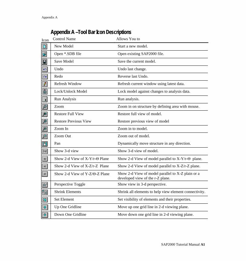
Appendix A –Tool Bar Icon DescriptionsIcon Control Name Allows You to
New Model Start a new model.
Open *.SDB file Open existing SAP2000 file.
Save Model Save the current model.
Undo Undo last change.
Redo Reverse last Undo.
Refresh Window Refresh current window using latest data.
Lock/Unlock Model Lock model against changes to analysis data.
Run Analysis Run analysis.
Zoom Zoom in on structure by defining area with mouse.
Restore Full View Restore full view of model.
Restore Previous View Restore previous view of model
Zoom In Zoom in to model.
Zoom Out Zoom out of model.
Pan Dynamically move structure in any direction.
Show 3-d view Show 3-d view of model.
Show 2-d View of X-Y/r-Θ Plane Show 2-d View of model parallel to X-Y/r-Θ plane.
Show 2-d View of X-Z/r-Z Plane Show 2-d View of model parallel to X-Z/r-Z plane.
Show 2-d View of Y-Z/Θ-Z Plane Show 2-d View of model parallel to X-Z plain or adeveloped view of the r-Z plane.
Perspective Toggle Show view in 3-d perspective.
Shrink Elements Shrink all elements to help view element connectivity.
Set Element Set visibility of elements and their properties.
Up One Gridline Move up one grid line in 2-d viewing plane.
Down One Gridline Move down one grid line in 2-d viewing plane.
Appendix B
SAP2000 Tutorial Manual A2
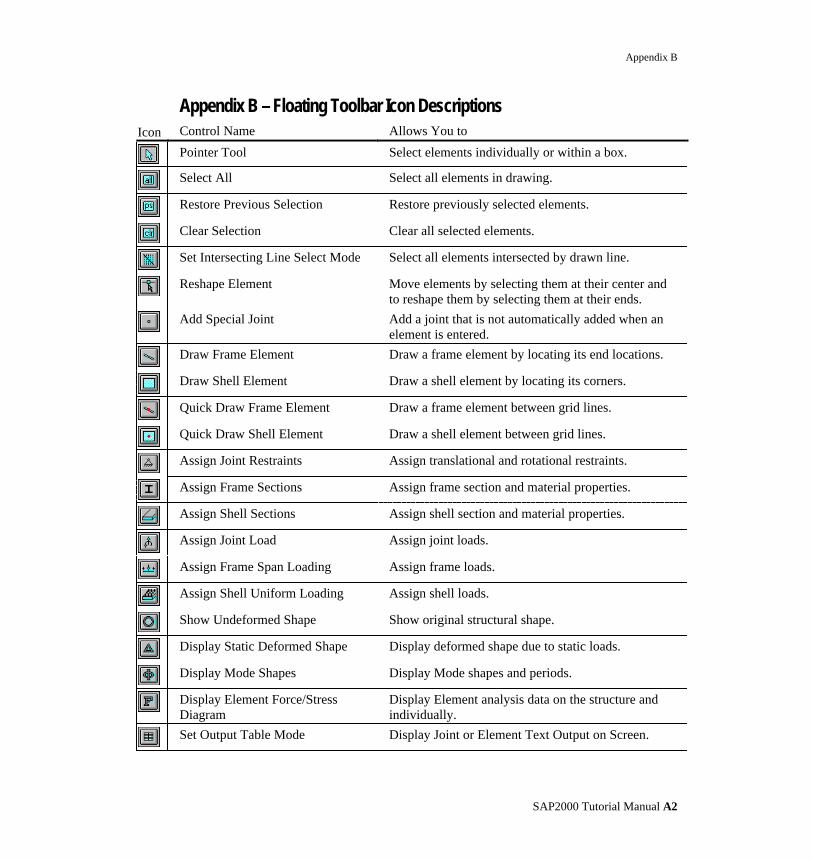
Appendix B – Floating Toolbar Icon DescriptionsIcon Control Name Allows You to
Pointer Tool Select elements individually or within a box.
Select All Select all elements in drawing.
Restore Previous Selection Restore previously selected elements.
Clear Selection Clear all selected elements.
Set Intersecting Line Select Mode Select all elements intersected by drawn line.
Reshape Element Move elements by selecting them at their center andto reshape them by selecting them at their ends.
Add Special Joint Add a joint that is not automatically added when anelement is entered.
Draw Frame Element Draw a frame element by locating its end locations.
Draw Shell Element Draw a shell element by locating its corners.
Quick Draw Frame Element Draw a frame element between grid lines.
Quick Draw Shell Element Draw a shell element between grid lines.
Assign Joint Restraints Assign translational and rotational restraints.
Assign Frame Sections Assign frame section and material properties.
Assign Shell Sections Assign shell section and material properties.
Assign Joint Load Assign joint loads.
Assign Frame Span Loading Assign frame loads.
Assign Shell Uniform Loading Assign shell loads.
Show Undeformed Shape Show original structural shape.
Display Static Deformed Shape Display deformed shape due to static loads.
Display Mode Shapes Display Mode shapes and periods.
Display Element Force/StressDiagram
Display Element analysis data on the structure andindividually.
Set Output Table Mode Display Joint or Element Text Output on Screen.