Embed Size (px)
Citation preview
ADCA
VALSTEAM ADCA We reserve the right to change the design and material of this product without notice.
IS PS161.015 E 00.21
The ADCAPure PS161 is a series of angle design direct acting diaphragm sensing pressure sustaining valves. These regulators, available with spring or dome-loading, are designed for use with clean steam, compressed air, water and other gases or liquids compatible with the construction materials and valve design.
Spring or dome-loaded. Non-rising adjustment knob.Compact design with clamped body. Available with low pressure diaphragm. FDA / USP Class VI compliant seals. Optimized internal designed to provide high flow capacities and minimum droop.Completely machined from bar stock material, no castings or forgings are used.
SANITARY PRESSURE SUSTAINING VALVEPS161
OPTIONS:
USE:
AVAILABLE MODELS:
SIZES:
REGULATING RANGES:
CONNECTIONS:
PACKAGING:
INSTALLATION:
Leakage line connection 1/8” (captured vent). Different soft sealings for liquids and gases.Gauge connection on body.Top cap (adjustment screw with cover).Dome-loaded version.
Clean steam, compressed air, water and other gases and liquids compatible with the construction.
PS161.
1/2” to 2”; DN 15 to 50.
0,8 to 1,5 bar; 1 to 3 bar; 1,5 to 5 bar.
ASME BPE, DIN and ISO clamp ferrules or tube weld (ETO) ends. Others on request.
Assembling and packaging in a clean room certified according to ISO 14644-1.The product is end capped and sealed with recyclable thermo-shrinkable plastic film, to avoid contamination.
Horizontal installation. Horizontal inlet and vertical outlet angle connection. See IMI.
Internal wetted parts: ≤ 0,51 micron Ra – SF1.External: ≤ 0,76 micron Ra – SF3.Other surface conditions see IS PV20.00 E – Technical information.Ultrasonic cleaning.
LIMITING CONDITIONS
Valve model PS161Body design conditions PN 16
Maximum upstream pressure 8 bar
Minimum upstream pressure 0,8 bar
Maximum operating temperature * 180 ºC* With PTFE diaphragm and seals. Consult the manufacturer in case of other elastomer materials.
CE MARKING – GROUP 2 (PED – European Directive)
PN 16 Category1/2” to 2” – DN 15 to 50 SEP
DESCRIPTION
MAIN FEATURES
STANDARD SURFACE FINISH
ADCA
A
HF
B
C
D
d4
C1
D
d2d1
E
d3
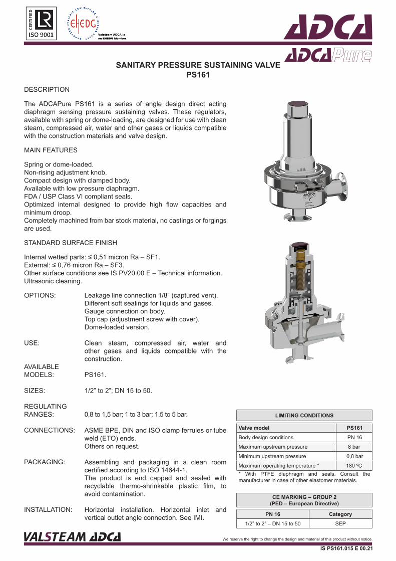
Optional pressure gauge connections.Optional dome-loaded version.
VALSTEAM ADCA We reserve the right to change the design and material of this product without notice.
IS PS161.015 E 00.21
VALSTEAM ADCA We reserve the right to change the design and material of this product without notice.
IS PS161.015 E 00.21
DIMENSIONS (mm) ASME BPE
SIZE A B C C1 D d1 d2 d3 * d4 * E F H WGT.(kg)
1/2” 77 53 156 84 119 25 15,75 1/4” 1/4” 83 25 9,4 4,13/4” 77 56 160 88 119 25 15,75 1/4” 1/4” 83 25 15,75 4,41” 77 52 163 91 119 25 15,75 1/4” 1/4” 83 50,5 22,1 4,6
11/2” 85 61 204 124 134 25 15,75 1/4” 1/4” 96 50,5 34,8 82” 85 67 207 127 134 25 15,75 1/4” 1/4” 96 64 47,5 8,6
DIMENSIONS (mm) DIN
SIZE A B C C1 D d1 d2 d3 * d4 * E F H WGT.(kg)
DN 15 77 45 160 88 119 25 15,75 1/4” 1/4” 83 34 16 4,4DN 20 77 40 158 86 119 25 15,75 1/4” 1/4” 83 34 20 4,3DN 25 84 47 161 89 119 25 15,75 1/4” 1/4” 83 50,5 26 4,6DN 32 84 50 163 91 119 25 15,75 1/4” 1/4” 83 50,5 32 4,8DN 40 93 69 202 122 134 25 15,75 1/4” 1/4” 96 50,5 38 8DN 50 93 75 206 126 134 25 15,75 1/4” 1/4” 96 64 50 8,6
Remarks: Clamp ferrules according to DIN 32676-A; Tube weld (ETO) according to DIN 11866-A (DIN 11850-2).
DIMENSIONS (mm) ISO
SIZE A B C C1 D d1 d2 d3 * d4 * E F H WGT.(kg)
DN 15 84 43 159 87 119 25 15,75 1/4” 1/4” 83 50,5 18,1 4,4DN 20 84 46 162 90 119 25 15,75 1/4” 1/4” 83 50,5 23,7 4,6DN 25 84 49 164 92 119 25 15,75 1/4” 1/4” 83 50,5 29,7 4,8DN 32 93 70 202 122 134 25 15,75 1/4” 1/4” 96 64 38,4 8,2DN 40 93 75 206 126 134 25 15,75 1/4” 1/4” 96 64 44,3 8,8
Remarks: Clamp ferrules according to DIN 32676-B; Tube weld (ETO) according to DIN 11866-B (ISO 1127).* As standard, connections d3 and d4 are female threaded ISO 7 Rp.
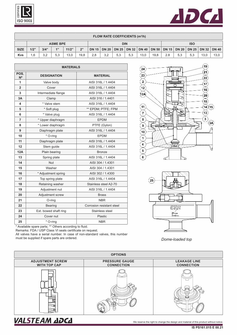
ADCAFLOW RATE COEFFICIENTS (m³/h)
ASME BPE DIN ISOSIZE 1/2” 3/4” 1” 11/2” 2” DN 15 DN 20 DN 25 DN 32 DN 40 DN 50 DN 15 DN 20 DN 25 DN 32 DN 40Kvs 1,6 3,2 5,3 13,0 19,8 2,8 3,2 5,3 5,3 13,0 19,8 2.8 5,3 5,3 13,0 13,0
MATERIALS
POS. Nº DESIGNATION MATERIAL
1 Valve body AISI 316L / 1.44042 Cover AISI 316L / 1.44043 Intermediate flange AISI 316L / 1.4404
3A Clamp AISI 316 / 1.44014 * Valve stem AISI 316L / 1.44045 * Soft plug ** EPDM; PTFE; FPM6 * Valve plug AISI 316L / 1.44047 * Upper diaphragm EPDM8 * Lower diaphragm PTFE (Gylon)9 Diaphragm plate AISI 316L / 1.4404
10 * O-ring EPDM11 Diaphragm plate AISI 316L / 1.440412 Stem guide AISI 316L / 1.4404
12A Plain bearing Bronze13 Spring plate AISI 316L / 1.440414 Nut AISI 304 / 1.430115 Washer AISI 304 / 1.430116 * Adjustment spring AISI 302 / 1.430017 Top spring plate AISI 316L / 1.440418 Retaining washer Stainless steel A2-7019 Adjustment nut AISI 316L / 1.440420 Adjustment screw Brass21 O-ring NBR22 Bearing Corrosion resistant steel23 Ext. bowed shaft ring Stainless steel24 Cover nut Plastic25 * O-ring NBR
* Available spare parts; ** Others according to fluid.Remarks: FDA / USP Class VI seals certificate on request.All valves have a serial number. In case of non-standard valves, this number must be supplied if spare parts are ordered.
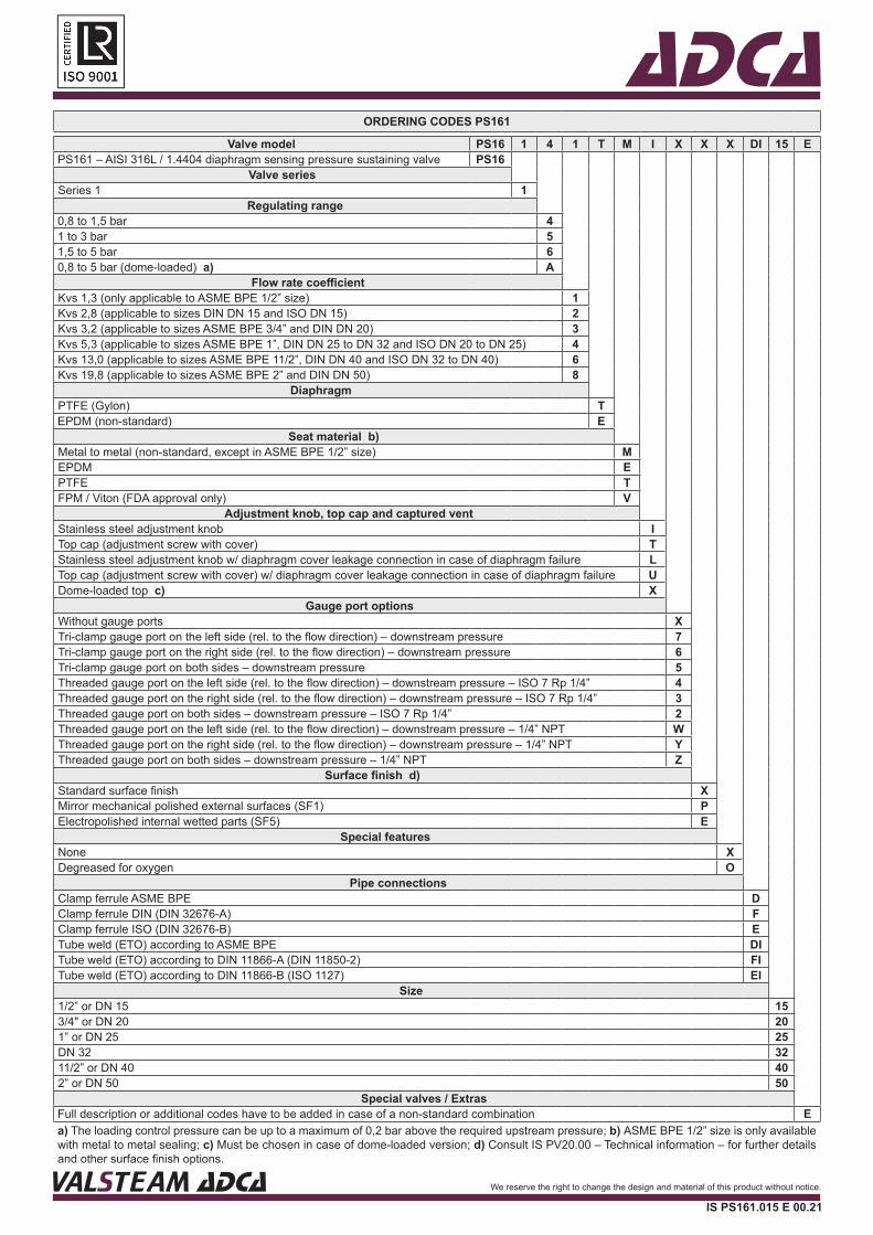
OPTIONS
ADJUSTMENT SCREW WITH TOP CAP
PRESSURE GAUGE CONNECTION
LEAKAGE LINE CONNECTION
VALSTEAM ADCA We reserve the right to change the design and material of this product without notice.
IS PS161.015 E 00.21
VALSTEAM ADCA We reserve the right to change the design and material of this product without notice.
IS PS161.015 E 00.21
Dome-loaded top
ADCAORDERING CODES PS161
Valve model PS16 1 4 1 T M I X X X DI 15 EPS161 – AISI 316L / 1.4404 diaphragm sensing pressure sustaining valve PS16
Valve seriesSeries 1 1
Regulating range0,8 to 1,5 bar 41 to 3 bar 51,5 to 5 bar 60,8 to 5 bar (dome-loaded) a) A
Flow rate coefficientKvs 1,3 (only applicable to ASME BPE 1/2” size) 1Kvs 2,8 (applicable to sizes DIN DN 15 and ISO DN 15) 2Kvs 3,2 (applicable to sizes ASME BPE 3/4” and DIN DN 20) 3Kvs 5,3 (applicable to sizes ASME BPE 1”, DIN DN 25 to DN 32 and ISO DN 20 to DN 25) 4Kvs 13,0 (applicable to sizes ASME BPE 11/2”, DIN DN 40 and ISO DN 32 to DN 40) 6Kvs 19,8 (applicable to sizes ASME BPE 2” and DIN DN 50) 8
DiaphragmPTFE (Gylon) TEPDM (non-standard) E
Seat material b)Metal to metal (non-standard, except in ASME BPE 1/2” size) MEPDM EPTFE TFPM / Viton (FDA approval only) V
Adjustment knob, top cap and captured ventStainless steel adjustment knob ITop cap (adjustment screw with cover) TStainless steel adjustment knob w/ diaphragm cover leakage connection in case of diaphragm failure LTop cap (adjustment screw with cover) w/ diaphragm cover leakage connection in case of diaphragm failure UDome-loaded top c) X
Gauge port optionsWithout gauge ports XTri-clamp gauge port on the left side (rel. to the flow direction) – downstream pressure 7Tri-clamp gauge port on the right side (rel. to the flow direction) – downstream pressure 6Tri-clamp gauge port on both sides – downstream pressure 5Threaded gauge port on the left side (rel. to the flow direction) – downstream pressure – ISO 7 Rp 1/4” 4Threaded gauge port on the right side (rel. to the flow direction) – downstream pressure – ISO 7 Rp 1/4” 3Threaded gauge port on both sides – downstream pressure – ISO 7 Rp 1/4” 2Threaded gauge port on the left side (rel. to the flow direction) – downstream pressure – 1/4” NPT WThreaded gauge port on the right side (rel. to the flow direction) – downstream pressure – 1/4” NPT YThreaded gauge port on both sides – downstream pressure – 1/4” NPT Z
Surface finish d)Standard surface finish XMirror mechanical polished external surfaces (SF1) PElectropolished internal wetted parts (SF5) E
Special featuresNone XDegreased for oxygen O
Pipe connections Clamp ferrule ASME BPE DClamp ferrule DIN (DIN 32676-A) FClamp ferrule ISO (DIN 32676-B) ETube weld (ETO) according to ASME BPE DITube weld (ETO) according to DIN 11866-A (DIN 11850-2) FITube weld (ETO) according to DIN 11866-B (ISO 1127) EI
Size1/2” or DN 15 153/4" or DN 20 201” or DN 25 25DN 32 3211/2” or DN 40 402” or DN 50 50
Special valves / ExtrasFull description or additional codes have to be added in case of a non-standard combination Ea) The loading control pressure can be up to a maximum of 0,2 bar above the required upstream pressure; b) ASME BPE 1/2” size is only available with metal to metal sealing; c) Must be chosen in case of dome-loaded version; d) Consult IS PV20.00 – Technical information – for further details and other surface finish options.
VALSTEAM ADCA We reserve the right to change the design and material of this product without notice.
IS PS161.015 E 00.21