Embed Size (px)
Citation preview

HochschuleBonn-Rhein-SiegUniversity of Applied Sciences
Fachbereich InformatikDepartment of Computer Science
Bachelor thesis
Practical project in the study programBusiness Information Systems
Sandboxing remote code executionin the distributed system RCE
by
Marc Julian Stammerjohann
First examiner: Prof. Dr. Andreas PriesnitzSecond examiner: Prof. Dr. Sascha Alda
Submitted on: 19.09.2016

Statutory declaration
Marc Julian StammerjohannAuf dem Blocksberg 17B53773 Hennef
Declaration of Authorship
I hereby declare that the thesis submitted is my own unaided work. All direct or indirect sourcesused are acknowledged as references.
This paper was not previously presented to another examination board and has not beenpublished.
Signature City and date
II

Contents
Statutory declaration II
List of Figures V
List of Tables VI
List of Abbreviations VII
1 Introduction 11.1 Sandboxing . . . . . . . . . . . . . . . . . . . . . . . . . . . . . . . . . . . . 11.2 Constrained execution . . . . . . . . . . . . . . . . . . . . . . . . . . . . . . . 2
2 Isolation techniques for software systems 32.1 Virtual Machine-based isolation . . . . . . . . . . . . . . . . . . . . . . . . . 4
2.1.1 Hypervisor-based isolation . . . . . . . . . . . . . . . . . . . . . . . . . 52.1.2 Container-based isolation . . . . . . . . . . . . . . . . . . . . . . . . . 6
2.2 Sandbox-based isolation . . . . . . . . . . . . . . . . . . . . . . . . . . . . . . 72.3 Comparison of techniques . . . . . . . . . . . . . . . . . . . . . . . . . . . . . 10
3 Remote Component Environment 123.1 Architecture of RCE . . . . . . . . . . . . . . . . . . . . . . . . . . . . . . . . 12
3.1.1 OSGi Service Platform and Eclipse Equinox . . . . . . . . . . . . . . . 133.1.2 RCE framework . . . . . . . . . . . . . . . . . . . . . . . . . . . . . . 15
3.2 Application area of RCE . . . . . . . . . . . . . . . . . . . . . . . . . . . . . . 193.3 Relevance of isolation techniques for RCE . . . . . . . . . . . . . . . . . . . . 19
4 Development of a sandbox prototype for RCE 204.1 Requirements analysis . . . . . . . . . . . . . . . . . . . . . . . . . . . . . . . 20
4.1.1 Usability of security . . . . . . . . . . . . . . . . . . . . . . . . . . . . 234.1.2 Usability of the Java policy tool . . . . . . . . . . . . . . . . . . . . . 24
4.2 Overview of the Java Security model . . . . . . . . . . . . . . . . . . . . . . . 254.2.1 Java Sandbox model . . . . . . . . . . . . . . . . . . . . . . . . . . . 254.2.2 Security in Eclipse Equniox/OSGi . . . . . . . . . . . . . . . . . . . . . 30
4.3 Identification of elements requesting access to system resources . . . . . . . . 354.4 Classification of the sandbox prototype of RCE . . . . . . . . . . . . . . . . . 374.5 Design and implementation of the sandbox prototype for RCE . . . . . . . . . 39
4.5.1 Design . . . . . . . . . . . . . . . . . . . . . . . . . . . . . . . . . . . 394.5.2 Implementation . . . . . . . . . . . . . . . . . . . . . . . . . . . . . . 44
4.6 Framework architecture . . . . . . . . . . . . . . . . . . . . . . . . . . . . . . 49
5 Evaluation of the sandbox prototype 515.1 Security . . . . . . . . . . . . . . . . . . . . . . . . . . . . . . . . . . . . . . 515.2 User experience . . . . . . . . . . . . . . . . . . . . . . . . . . . . . . . . . . 52
6 Conclusion and Future Work 53
Bibliography 55
A Appendix 57A.1 Sandbox classes summary . . . . . . . . . . . . . . . . . . . . . . . . . . . . . 57A.2 Developer instruction (user story I1) . . . . . . . . . . . . . . . . . . . . . . . 59
III

Contents
A.3 Logging result . . . . . . . . . . . . . . . . . . . . . . . . . . . . . . . . . . . 60A.4 Final product backlog . . . . . . . . . . . . . . . . . . . . . . . . . . . . . . . 62A.5 Test suites . . . . . . . . . . . . . . . . . . . . . . . . . . . . . . . . . . . . . 63
IV

List of Figures
1 Generic isolation model . . . . . . . . . . . . . . . . . . . . . . . . . . . . . . 32 Hypervisor-based Virtualization . . . . . . . . . . . . . . . . . . . . . . . . . . 53 Container-based Virtualization . . . . . . . . . . . . . . . . . . . . . . . . . . 64 Sandbox-based Isolation . . . . . . . . . . . . . . . . . . . . . . . . . . . . . . 85 Sandbox techniques . . . . . . . . . . . . . . . . . . . . . . . . . . . . . . . . 97 RCE architecture . . . . . . . . . . . . . . . . . . . . . . . . . . . . . . . . . 128 OSGi Framework layer . . . . . . . . . . . . . . . . . . . . . . . . . . . . . . . 139 RCE framework layers . . . . . . . . . . . . . . . . . . . . . . . . . . . . . . . 1510 RCE instance . . . . . . . . . . . . . . . . . . . . . . . . . . . . . . . . . . . 1611 Example workflow execution . . . . . . . . . . . . . . . . . . . . . . . . . . . 1712 Java anatomy with Security Manager and Access Controller . . . . . . . . . . 2613 Security Model of JDK 1.0.x . . . . . . . . . . . . . . . . . . . . . . . . . . . 2814 Enhanced Security Model of JDK 1.2 . . . . . . . . . . . . . . . . . . . . . . . 2915 Stack trace during a security check . . . . . . . . . . . . . . . . . . . . . . . . 3016 UML class diagram of the Eclipse Equinox/OSGi Sandbox model . . . . . . . . 3117 UML sequence diagram: example interaction during a security check . . . . . . 3518 Sandbox properties of Java and OSGi . . . . . . . . . . . . . . . . . . . . . . 3819 Concept UML Use Case diagram . . . . . . . . . . . . . . . . . . . . . . . . . 4120 Permission control dialog prototype . . . . . . . . . . . . . . . . . . . . . . . . 4221 UML Class diagram: Manager implementation . . . . . . . . . . . . . . . . . . 4222 User prompt dialog . . . . . . . . . . . . . . . . . . . . . . . . . . . . . . . . 4323 UML Class diagram prototype design . . . . . . . . . . . . . . . . . . . . . . . 4424 Permission Control Dialog . . . . . . . . . . . . . . . . . . . . . . . . . . . . . 4625 User prompt dialog . . . . . . . . . . . . . . . . . . . . . . . . . . . . . . . . 4826 UML Class diagram prototype implementation . . . . . . . . . . . . . . . . . . 4927 RCE Framework with the new security layer . . . . . . . . . . . . . . . . . . . 5028 UML class diagram of the Java 2 Sandbox model . . . . . . . . . . . . . . . . 5729 Client 1 and 2: Bundles requesting socket permission . . . . . . . . . . . . . . 6030 Server: Bundles requesting socket permission . . . . . . . . . . . . . . . . . . 61
V

List of Tables
1 Hypversior-based vs. Container–based technique . . . . . . . . . . . . . . . . . 112 Virtual Machine-based vs. Sandbox-based technique . . . . . . . . . . . . . . . 113 Stakeholder . . . . . . . . . . . . . . . . . . . . . . . . . . . . . . . . . . . . 204 Product Backlog . . . . . . . . . . . . . . . . . . . . . . . . . . . . . . . . . . 215 Traceability matrix . . . . . . . . . . . . . . . . . . . . . . . . . . . . . . . . . 226 Technical key data of the RCE framework . . . . . . . . . . . . . . . . . . . . 237 Requested permissions . . . . . . . . . . . . . . . . . . . . . . . . . . . . . . . 378 Sandbox prototype classification . . . . . . . . . . . . . . . . . . . . . . . . . 389 Provided Java classes of the default sandbox model . . . . . . . . . . . . . . . 5810 Final Product Backlog . . . . . . . . . . . . . . . . . . . . . . . . . . . . . . . 62
VI

List of Abbreviations
ABI Application Binary Interface
ACL Access Control List
API Application Programming Interface
CPACS Common Parametric Aircraft Configuration Scheme
CPAS Conditional Permission Admin Service
DLR Deutsches Zentrum fur Luft- und Raumfahrtdro
EPL Eclipse Public License
IDE Integrated development environment
ISA Instruction Set Architecture
JDK Java Development Kit
JVM Java Virtual Machine
Malware Malicious Software
OS Operating System
OSGi Open Services Gateway initiative
PAS Permission Admin Service
RCE Remote Component Environment
RCP Eclipse Rich Client Platform
SWT Standard Widget Toolkit
VM Virtual Machine
VII

1 Introduction
Scientists and engineers are using a distributed system Remote Component Environment (RCE)to design and simulate complex systems like airplanes, ships and satellites. During the simulation,RCE executes local and remote code. Remote code is classified as untrusted code. The executionof remote code comprises potential security risks for the host system of RCE. Additionally, RCEprovides full access to system resources. The objective of this thesis is to implement a sandboxprototype to reduce the vulnerability of RCE during the execution of remote code.
1.1 Sandboxing
Software systems execute source code. Source code is classified as local or remote codedepending on the level of trust. Local code is developed by a known and trusted developer.Remote code is provide by either a known or unknown developer on a network such as theinternet. For that reason, remote code is regarded with suspicion since the source of the remotecode is untrusted, and therefore could be malicious [GMPS97].
The motive to download and execute remote code is to add new or additional functionalityto a software system. The most common type of software systems that rely on remote codeexecution are web browsers. The programming language Java Script is implemented on manyweb pages to provide additional functionality for the user. A web page accessed from theinternet downloads and executes Java Script within the Browser. Applications, better known asApps, which are developed by third parties for an mobile operating system. The execution ofremote code is an important aspect of software systems, however, it involves potential securityrisks.
A comprised system that manipulates or spies on personal data is a possible consequence ofexecuting remote code. Hence, it can be considered malicious, intentionally or unintentionally[AS11]. For example, data can be manipulated by unintentional programming mistakes.Ransomware is a recent intentional threat spreading through Word or PDF files that attemptsto encrypt all data on a computer. Therefore, remote code should only get limited permissionsto access resources, such as files and networks.
Researchers became interested in developing and improving isolation methods to reduce thelikelihood of attacks caused by executing remote code. An important approach in this spirit iscalled Sandboxing. A sandbox creates an isolated environment within an operating system. Itcontrols and limits the access of remote code to resources outside the isolated environment,thus protecting the operating system from any unexpected and undesired effects of remotecode running within the sandbox. Due to the rapid development of the internet, sandboxing isan essential method to improve the security of software systems. Sandboxing is used in variousrelevant products such as the Chrome Browser, the Android Operating System (OS) and theAdobe Reader [MSCS16].
Researchers who investigate in sandboxing put a strong focus on security and engineeringaspects of sandboxes. However, the usability aspect and the consequences of sandboxingfor the user are mostly disregarded [MSCS16]. Therefore, it is worthwhile to consider theimplementation of sandboxing in a software application and to identify the resulting consequencesfor the user experience.
The Eclipse-based application RCE is an open source framework for scientists and engineersto design and simulate complex systems like airplanes and satellites. The two main feature arethat RCE is developed as a distributed environment and supports a reusable component-basedapproach. Different users can work together on a complex system via a network of RCEinstances. RCE has full access to system resources which makes the system vulnerable to
1
1 Introduction
malicious code executed within RCE. Therefore, isolation techniques are interesting for RCE torestrict the access of resources and reduce the system vulnerability.
1.2 Constrained execution
RCE grants permission to access system resources during the simulation of a complex system.A simulation of complex systems consists of local and remote components. Therefore, RCE isextremely vulnerable to malicious code contained in a remote component. The execution of amalicious remote component may harm or manipulate the system. It remains to be examinedwhether there is an effective method to secure RCE. Isolation techniques are considered toconstrain remote code execution. Among the isolation techniques, sandboxing allows to controland limit permissions granted to access any system resource.
The objective of this thesis is to design and implement a sandbox prototype to secure RCE.Existing sandbox models, which are available for implementing the prototype, are analyzed anddescribed and elements of RCE with access to system resource are identified to support theimplementation. Additionally, the effects that the sandbox prototype has on both security andthe user experience through the RCE application are discussed and reflected.
2
2 Isolation techniques for software systems
Computers are used for various functions like video editing, programming and web surfing.Isolation provides a protection barrier in a computer system to prevent functions from disturbingeach other. The isolation of computers is reduced by connecting computers to a network orperforming several functions on a single computer. Vulnerabilities of a computer system canbe exploited and the whole system can be compromised with missing isolation. Therefore,the general purpose of isolation techniques is to protect a computer system against exploitingvulnerabilities [VN10].
Isolation techniques are essential in computer security and have been introduced in 1972by James Anderson, before the arrival of the internet and the wide distribution of personalcomputer. At that time, isolation techniques were considered, because security and privacyproblems rose with the occurrence of computer systems capable of sharing resources. Usersare provided with features to share operations and data with other users. Those featuresare extended to computer networks. Security issues were caused by concurrent executionof processes and storing sensible data in the same memory regardless of the different userpermissions. The execution of programs should be controlled to ensure a secure environmentfor sharing system resources [And72].
In recent years, the need for isolation techniques increases, due to the constant growth ofnetwork-compatible devices such as laptops, desktop computers and mobile devices. Furthermore,the rapid development and the increasing importance of the internet increased the demand forisolation techniques. The logic of computer security is subject to constant changes, becauseof the combination of these devices with the internet and the continuous distribution of newdevices and the internet [VN10].
The increasing importance of network-compatible devices makes new types of attacks possibleand increases them. Malicious Software (Malware) is the umbrella term for various attackssuch as worms, viruses, ransomware and Trojan horses. Malware infects one part of thecomputer system and tries to gain access to the rest of the system or even to the network[VN10]. Isolation techniques have the potential to limit or even avoid the effect caused by aMalware attack. The usage of isolation techniques has evolved to be used by software engineersnot only for security in software systems, but also for modular design of software componentsand to isolate the failures of components [VN10].
Protection Domain Task
System Resource
Protection Domain
TaskTask
System Resource
Protection Domain
Task
Task
System Resource
TaskTask
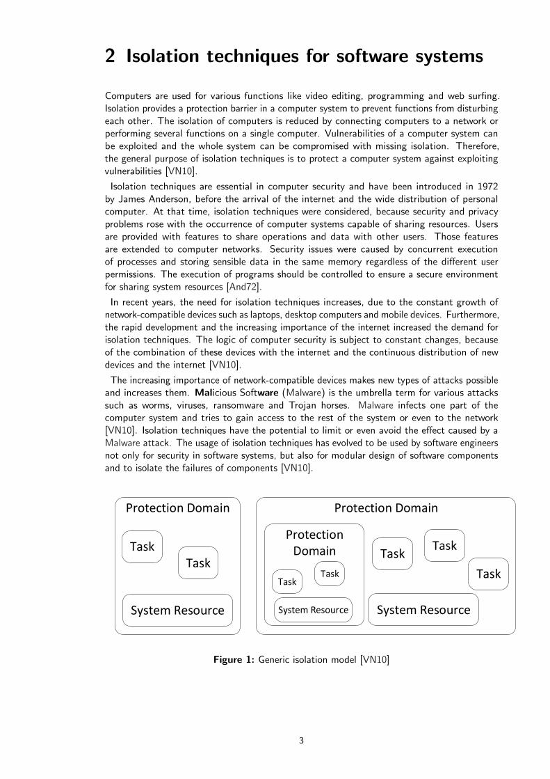
Figure 1: Generic isolation model [VN10]
3

2 Isolation techniques for software systems
Figure 1 visualizes a generic model of isolation in a computer system. The model consistof Tasks, System Resources and Protection Domains. Every type of software using systemresources to execute an individual function falls into the abstract description of a task. Softwaresuch as a web browser or a text editor are examples for tasks. The system comprises a set ofresources such as file system, network or CPU and a system resource is at least one element ofthe set. Tasks share the resources during the execution of their function. Resource sharing raisessecurity issues. However, it is essential for an efficient usage of the resources. A protectiondomain encapsulates the system resources and tasks. It implements a protection policy by usingan isolation technique. Furthermore, the model permits protection domains to be within otherprotection domains [VN10].
Isolation techniques for software systems are known as Virtual Machine (VM)-based isolation,sandbox-based isolation, language-based isolation, OS-kernel-based isolation, hardware-basedisolation and physical isolation. VM-based isolation can be divided into multiple approachessuch as Hypervisor-based and Container-based virtualization. The sandbox isolation has threecommon approaches referred to as Instruction Set Architecture (ISA)-based, ApplicationBinary Interface (ABI)-based and Access Control List (ACL)-based [VN10]. The followingsections describe and compare the three most common used isolation techniques in more detail:Hypervisor-based, Container-based and Sandbox-based.
2.1 Virtual Machine-based isolation
A Virtual Machine is a software abstraction of a physical machine and it provides a virtualplatform for executing tasks. The virtual platform can either execute an entire operating systemor customized processes which differ based on the abstraction level of the virtual machine[VN10]. Multiple VMs can be installed and executed on the same hardware. VM-based isolationis referred to as virtualization technology and the usage has increased sharply in recent years.The requirements for virtualization solutions are efficiency, scaling and secure user environments.Different approaches emerge in the market of virtualization technologies. Container-based andhypervisor-based isolation are established as core technologies. Other approaches are known asprocess-based, hosted-based and hardware-based isolation [Bui15, VN10].
Software engineers are using VM technologies to gain several benefits. The benefits of VM areisolation, hardware independence and increased scalability [MKK15]. Multiple VMs installedon the same hardware are isolated which increase the overall security of the guest and hostsystem. Once a guest system is compromised or produces an error the isolation prevents otherguests and even the host system to be affected [SN05].
Various technologies make use of VM ranging from desktop and server virtualization, pro-gramming languages to services offered in the cloud. Desktop virtualization enables to runmultiple Operating System on one computer. It establishes support for applications which runonly within specific OS. Server virtualization works similar and lets numerous virtual systemsrun on one server. The virtual systems imitate a physical server. A common business model isto rent the virtual systems in the cloud based on subscription. Amazon EC2, Rackspace andDreamHost are just a few providers of virtual servers in the cloud [Bui15].
Virtual servers are a great example for isolation and scaling. In terms of isolation, virtualservers can be used to execute one specific task using related data. Tasks running on a serverare not allowed to manipulate the data of other servers and therefore, increase the security.Virtual servers are easily scalable to increase or decrease capacities depending on the numberof requests and exchanged data [MKK15].
4

2 Isolation techniques for software systems
The programming language Java uses a process virtual machine as execution environment ofJava applications [VN10]. The virtual machine is called Java Virtual Machine (JVM). At thestart of a Java application, an instance of the JVM is initiated and the only purpose is to runthe application. Each started application is executed in its own JVM instance. The instancelives until the application is completed. The JVMs benefit is its platform independency. Hence,Java applications can be executed on various operating systems which offer an JVM such asWindows, Linux and MacOS [Ven00].
2.1.1 Hypervisor-based isolation
The hypervisor-based isolation technique illustrated in Figure 2 comprises of a Hypervisorengine and Virtual Machines. The technique creates the isolation at the hardware level [Bui15].It involves providing virtualized system resources, which result in overhead virtualizing thehardware and providing virtual drivers [MKK15]. The installed VMs run on top of the virtualizedsystem resources.
Hardware
Host OS
Hypervisor engine
Virtual Machine Virtual Machine
Guest OS
Dependencies
Task
Guest OS
Dependencies
Task
Figure 2: Hypervisor-based Virtualization [Bui15]
A VM contains an entire operating system and essential libraries and provides the platform forperforming tasks. The operating system executing the isolation technique is the host OS. AHypervisor engine operates between the host and the virtual machine referred to as guest system.The hardware resources are split up between all guest systems by the engine. Additionally, thehypervisor installs the virtual machines and controls all access starting from the guest system tothe hardware resources. The access control establishes the isolation among all virtual machines.The VM can be implemented in two different approaches. In the pure-isolation approach, theVMs are unable to share resources among each other. On the other hand, the sharing approachallows sharing resources between the VMs [VN10].
The hypervisor approach is used in the professional as well as in the private sector. Virtualmachines are useful for individual users in a company network. Each user has its own dedicatedvirtual machine which allocates relevant resources like computation power, memory and storage.The user is able to log in to the VM at work or remotely. The IT department can be centralizedthrough this approach by offering powerful physical machines to multiple users. It reducesthe expenses of installing and setting up individual computers at different locations. Other
5

2 Isolation techniques for software systems
operating systems can be executed in virtual environments on one host system, for exampleWindows can run on MacOS. The user is able to use the full range of applications supportedby the host and the guest operating systems. Furthermore, personal and business activities canbe separated with the VM approach. VMs find use for daily applications such as browsers andemail clients. In the presence of Malware only the VM is affected and the host system remainsunharmed [Oli]. It finds application for Malware analysis running suspicious applications withinvirtual machines and identifying the effects [MSCS16]
VMWare introduced virtualization software reshaping the application areas of virtual machinesin 2001. VMWare offers virtualization solutions for desktop and server. Oracle offers VirtualBoxa free and open-source virtualization application. It provides features for advanced users wholike to implement and use scripts to install virtual machines [Oli].
The isolation between the guest and host system is the benefit of hypervisor-based isolation interms of security. Damage caused by Malware or a software failure is limited to the VM whereit occurred. Therefore, other guest systems or even the host system is unharmed [SN05].
2.1.2 Container-based isolation
The isolation approach known as container-based isolation includes a Container engine andmultiple virtual environments called Container. The isolation is at the operating system level toavoid overhead. The host operating system kernel is used for providing the containers and toperforms tasks. Containers ship without a guest operating system. Therefore, it is also referredto as a lightweight virtualization approach [Bui15].
The container establishes the protection domain providing resources to execute the tasks.Resources can be either shared by the host or installed within the container. Containers looklike normal processes on the host. The container engine is located between the OS and librariesof the host machine. All containers are managed by the engine [Bui15]. The architecture ofthe container-based isolation is visualized in Figure 3.
Hardware
Host OS
Containers engine
Host OS libraries
Container
Dependencies
Task
Container
Dependencies
Task
Figure 3: Container-based Virtualization [MKK15]
6
2 Isolation techniques for software systems
The advantages of the lightweight approach are the small disk images which make it possibleto have a high density of container instances on one host machine. In addition, it offershigh performance in virtualization. However, containers are designed for specific operatingsystems. In other words, a Windows container can not be installed and executed on a Linuxhost. Another disadvantage is the lack of resource isolation, because the host kernel is visiblefor each container. It results in security concerns about the container-based approach [MKK15].
A container bundles an application and its dependencies, libraries and other necessary files. Itsolves the problem to deploy and move software reliable between systems with different softwareenvironments. Therefore, the technique is often used for improving the development processincluding tests and production of an application. The whole container is easily moved fromone platform to the other without causing problems [Rub]. Software containers are designedlike shipping containers to provide efficiency and to reduce cost just for data center. The fastboot time of containers allow to quickly add more capacities by starting new containers on aserver to handle more requests. For example, Google uses a container approach for their searchengine handling increases and decreases of occurring search queries [Bab].
The open source container technology Docker has the most success in the sector. It has threemain features building, shipping and running of distributed applications. A single applicationcan be wrapped in a lightweight Docker container. It can run virtually on any operating systemwith an available Docker platform. In addition, the container creation and control can easilyand securely be managed by the included interface. Lastly, more lightweight Docker containerscan be installed on a single system compared with other virtualization technologies [Bui15].
The container approach provides isolation between all containers deployed on the same hostsystem. The security of the system is enhanced by the host allocating separate memory spacesfor each container. Containers are able to run an application undisturbed and the data access ofother containers is prevented. However, security concerns remain about the approach, becausethe operating kernel is exposed to each container deployed on the system [Bab].
2.2 Sandbox-based isolation
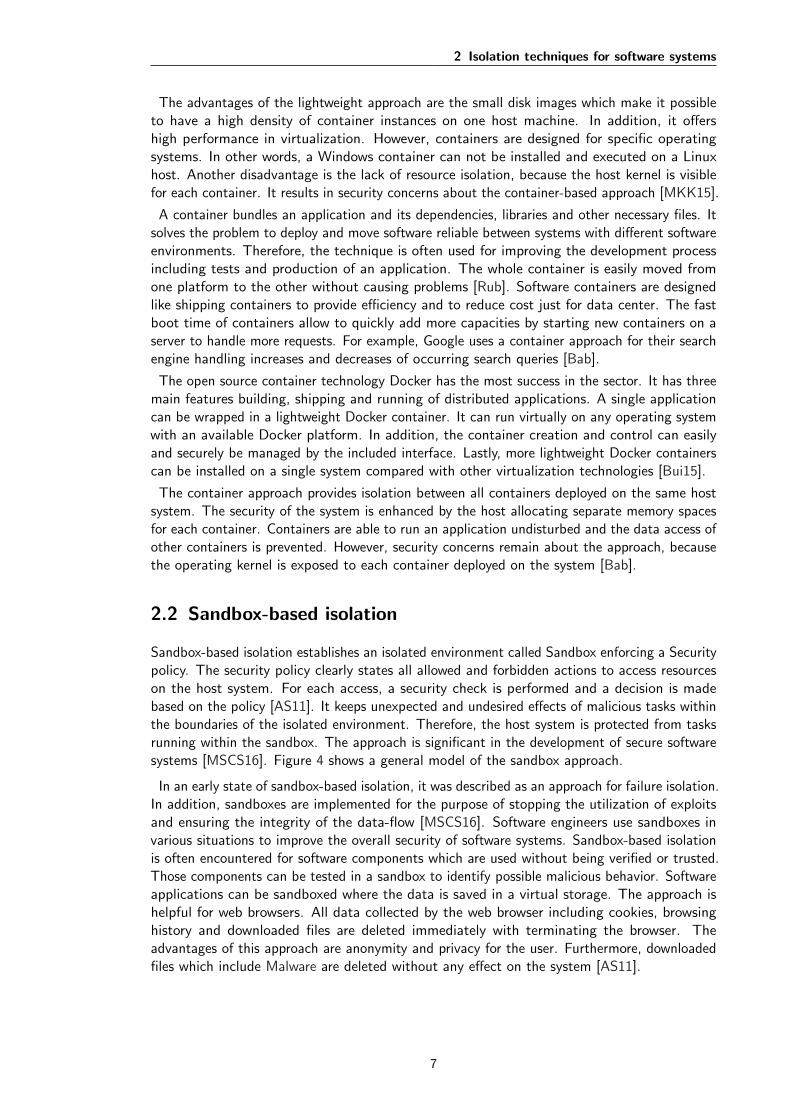
Sandbox-based isolation establishes an isolated environment called Sandbox enforcing a Securitypolicy. The security policy clearly states all allowed and forbidden actions to access resourceson the host system. For each access, a security check is performed and a decision is madebased on the policy [AS11]. It keeps unexpected and undesired effects of malicious tasks withinthe boundaries of the isolated environment. Therefore, the host system is protected from tasksrunning within the sandbox. The approach is significant in the development of secure softwaresystems [MSCS16]. Figure 4 shows a general model of the sandbox approach.
In an early state of sandbox-based isolation, it was described as an approach for failure isolation.In addition, sandboxes are implemented for the purpose of stopping the utilization of exploitsand ensuring the integrity of the data-flow [MSCS16]. Software engineers use sandboxes invarious situations to improve the overall security of software systems. Sandbox-based isolationis often encountered for software components which are used without being verified or trusted.Those components can be tested in a sandbox to identify possible malicious behavior. Softwareapplications can be sandboxed where the data is saved in a virtual storage. The approach ishelpful for web browsers. All data collected by the web browser including cookies, browsinghistory and downloaded files are deleted immediately with terminating the browser. Theadvantages of this approach are anonymity and privacy for the user. Furthermore, downloadedfiles which include Malware are deleted without any effect on the system [AS11].
7
2 Isolation techniques for software systems
Hardware
Host OS
Sandbox
Task TaskTask
Security controlSecurity Policy
Figure 4: Sandbox-based Isolation
Various relevant software make use of the sandbox approach to improve security by preventingMalware distribution and data manipulation of the system. The browser Google Chrome, theoperating system Android and the programming language Java are such examples providingbuild-in sandbox techniques. Google Chrome displays a web page in a single tab. Eachtab represents an independent process which is protected by its own sandbox. In additionto protecting the system against Malware, tabs are not capable of manipulating other tabprocesses. Malicious code executed in a tab cannot harm the browser or other tabs. The effectis contained and remains only until the tab is closed in the sandbox [BRJI08].
The security of Android is enhanced by executing applications in separate sandboxes. Theisolated environments are forbidden to access system resources such as contacts, calender orcamera, except user explicitly grants the permissions. Before installing an App, the user isasked to review the required permissions and the installation is only continued when those areaccepted. The purpose of the sandbox and permissions is to limit the consequences of bugsand vulnerabilities in Apps. The permission system was updated with Android 6.0 allowing theuser to manage the individual permissions at any time [Pro].
The first release of the programming language Java came with a sandbox model implementation.The purpose was to run remote code called Applets in an isolated environment to restrict theaccess to the system resources. In further releases of Java, the sandbox model was enhanced toprovide isolation also for local code and it is customizable for any Java application [GMPS97].
The sandbox approach improves the security of software systems by providing an isolatedenvironment and enforcing a security policy. The security benefits from the isolation andlimitation of damage to the system caused by software components executed within thesandbox. An important part is the security policy defining allowed and forbidden actions.Therefore, the sandbox is customizable for the desired system environment based on givenrequirements [MSCS16].
8
2 Isolation techniques for software systems
Classification and comparison of sandbox techniques
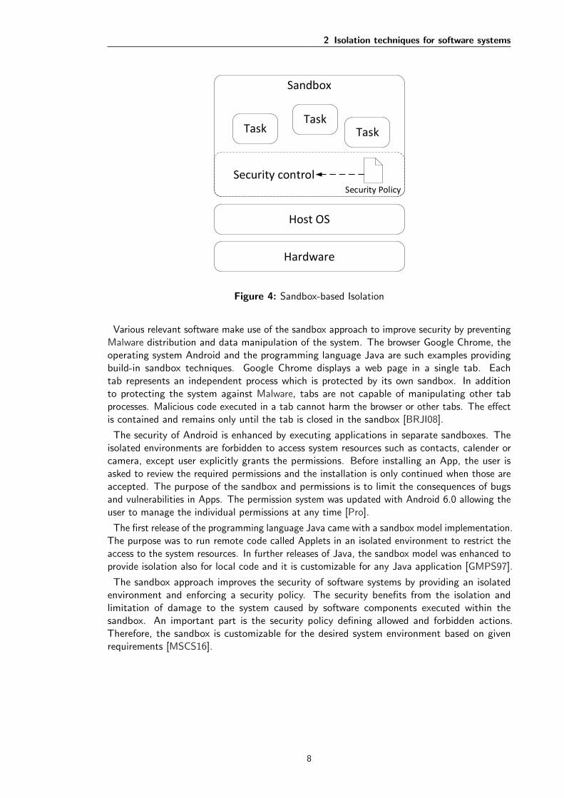
A sandbox can use one of three different sandbox techniques. Each technique has its ownadvantages and disadvantages in preventing a system from attacks. Possible side effectsof tasks can be limited at instruction level, operating system level or by performing accesscontrols to critical resources. These techniques correspond to the approaches Instruction SetArchitecture (ISA), Application Binary Interface (ABI) and Access Control List (ACL) [VN10].The following section describes and compares these three approaches.
Figure 5 illustrates the classification of the previously named sandbox approaches in a computersystem. The techniques are located on different layers. Hence, it results in distinct possibleuses for each approach.
Hardware
Host OS
Libraries
Task Task Task
ISA
ABI
ABI/ACL
Figure 5: Sandbox techniques [SN05]
Instruction Set Architecture
All sandboxes constraining activities of tasks at instruction level belong to the ISA technique.ISA is based on a well-defined interface between hardware and software as shown in Figure 5.The simplest implementation of the technique is rewriting binary code. Additional commandsare inserted before existing code for verification of memory access breaches. Disadvantages ofthe techniques is the dependency on the computer architecture and the type of command set[VN10].
Application Binary Interface
The interface providing tasks with access to resources of the system is called ABI [SN05]. Itis located between the OS and tasks or tasks and the used libraries. A ABI-based sandboxestablishes a restricted environment by preventing tasks to call the system. A sandbox of thiscategory confines the effects of tasks by regulating the used ABIs. Configuration files are acommon method to determine limited ABIs for the use of tasks [VN10].
Access Control List
A sandbox based on the ACL technique provides certain permissions to restrict tasks via accesscontrols. Permissions are available for system resources such as networks, files and processes.ACL-based is more generic for restricting tasks behavior compared with ABI-based [VN10].
9

2 Isolation techniques for software systems
2.3 Comparison of techniques
The comparison explains the differences and similarities of the three isolation techniquesdescribed above. The overall comparison of the techniques is visualized in Figure 6. Similarproperties of the techniques are symbolized with the dashed boxes. All three approaches createan isolated environment with different impact on containing and securing effects of malicioustasks.
Isolation
Sandbox
Security control
Security policy
impose
perform
provide
Container
OS level
Virtualization
provide
Hypervisor
Hardware level
establish
at
provide
at
establish
Figure 6: Isolation comparison
Hypervisor and container based isolation
Virtualization is the main purpose of both technologies as shown in figure 6. The technologiesestablish virtual environments of different scopes. The Table 1 describes the importantdifferences of both techniques. The hypervisor-based performance is slower compared tocontainer-based, because it needs to start a full operating system within the virtual environment.The included guest OS is the reason of the bigger size of VMs. The container approachships without a separate OS. Therefore, it is often described as the lightweight virtualizationapproach. The small container size allows to deploy ten times more virtual environments onone host system. However, the container must be from the same type as the host system. Forexample a Linux container cannot be started on a Windows host which is a disadvantage ofthe container approach. Hypervisor can deploy virtual machines of different types on severaloperating systems.
Both technologies provide an isolated environment as visualized in Figure 6. The isolationprovided by VMs keeps any unexpected effects within the virtual environment. On the otherhand, containers are considered unsecure, because the kernel of the operating system is exposedto all deployed containers. Security vulnerabilities of the kernel might be exploited to access ormanipulate a container [Bui15, MKK15, Rub].
10

2 Isolation techniques for software systems
Hypervisor-based Container-basedVirtualization Hardware level Operating system level
Virtual environment Full operating system andapplications
Application including de-pendencies and libraries
Isolation Between guest and hostsystem
Between other containers
Performance Slow boot time Quick boot time
Memory High usage for each guestOS
Low consumption for us-ing the host OS
Table 1: Hypversior-based vs. Container–based technique
Sandbox and Virtual machine based isolation
Isolation is only the main purpose of the sandbox approach. The sandbox approach imposesa security policy on which the security control makes decisions whether an action is allowedor forbidden. Therefore, the isolated environment is customizable to support the securityrequirements for a single software system by clearly defining and adjusting the policy.
Virtual Machine-based Sandbox-basedIsolation through Virtualization Security policy and controls
Constrained execution location Virtual environment Host system
Table 2: Virtual Machine-based vs. Sandbox-based technique
The virtual machine technique establishes a virtual environment which includes an isolationenvironment. All effects of tasks are isolated within the boundaries of the virtual environment.Hereby, the isolation enhances the overall security. Nevertheless, the virtual machine techniquescomes without an adjustable policy to specify which actions are allowed or forbidden. Virtualmachine-based is sometimes referred to as sandbox, because it also provides a constrainedexecution environment. However, both techniques establishes the constrained executionenvironment on a different location as shown in Table 2. On the one hand VM-based creates afull virtual machine to execute and constrain tasks. On the other hand sandbox techniquesperform and restrict tasks on the host system [VN10].
11

3 Remote Component Environment
The Deutsches Zentrum fur Luft- und Raumfahrt (DLR) began with the development of theRCE framework in 2005. This framework is based on a reusable component-based approach.The increasing complexity of software applications requires reuse of resources to minimizedevelopment time and reduce costs.
The main purpose of RCE is to provide an environment for the design, simulation andoptimization of complex systems, such as airplanes, satellites or ships. These simulationscan theoretically include every possible property of a complex system, such as geometry,aerodynamics and thermal management [SBM+13]. Exemplary projects are explained in section3.2. Scientists and engineers collaborate and contribute their knowledge to create the simulationof a complex system. Therefore, RCE is designed as a distributed environment. RCE connectsvarious computers into a common project environment. Additionally, it manages the exchangeof data between different computers. For this reason, the computations of a simulation canbe performed on different computers which contribute to an overall result [SFL+12]. In thefurther process, the term ”user” is used broadly when referring to scientists and engineers. Thefollowing section covers important aspects of RCE’s architecture which are relevant for thedevelopment of the sandbox prototype. In the process, relevant terms of the architecture aredescribed to be used for further explanations.
3.1 Architecture of RCE
The architecture of the RCE framework is laid out to meet the requirements for scientificapplications. The basic requirements of the framework are a component-based approach,providing extension features, supporting portability and using open-source licensing. In addition,other essential requirements are important for projects in the field of aeronautics and space.The simulation of complex systems require knowledge and tools of multiple users. For example,these tools can be custom simulations provided by a user. For collaboration purposes, theframework should be designed as distributed software. All scientific data should be recorded ina persistent storage. The framework should provide an environment for connecting componentsas a workflow and to execute the workflow. Finally, a graphical user interface should allow easycontrol over RCE for users.
Java
RCE
Eclipse RCP/OSGi
Figure 7: RCE architecture [SFL+12]
Figure 7 shows the overall framework architecture of RCE. Eclipse Rich Client Platform (RCP)is the foundation of RCEs framework. RCP corresponds with platform independence, supportsa component-based approach and is open-source. RCP is an essential framework for thedevelopment and research in aerospace and automotive industry. One of many reasons, it is
12

3 Remote Component Environment
implemented with Java, the free and modern programming language. Furthermore, RCP isbased on an Open Services Gateway initiative (OSGi) specification which is described in thefollowing subsection. [SFL+12].
3.1.1 OSGi Service Platform and Eclipse Equinox
The OSGi Service Platform provides a modular and dynamic framework for Java. The maincomponent of the OSGi Service Platform is the OSGi Framework as shown in Figure 8. Itestablishes a container for Bundles and Services. OSGi supports development of extensible andcomponent-based applications. Therefore, it corresponds well with the requirements of RCE.The framework manages the life cycle of required bundles at runtime.
OSGi Framework
System Resources
Execution Environment
Secu
rity
Module
Lifecycle
Service
Bundles
Figure 8: OSGi Framework layer [OSG11]
The OSGi framework is divided into security, module, life-cylce and service layer. Relatedfunctionalities are combined in the corresponding layer. Each layer defines important aspectsof the bundle concept in OSGi. Therefore, the actual bundles have contact points to all fourlayers as illustrated in figure 8. The Java security model of JDK 1.2 is the foundation ofthe OSGi security layer. Configuration of permissions for each bundle and real time updatesof permissions are provided as extensions. Two essential services from the security layer arementioned later in this section. Modularization in OSGi is specified by introducing the bundleconcept in the module layer. OSGi enforces strict rules about the visibility of Java packagesbetween bundles. The module layer can be used independent of other layers.
Life-cycle layer defines the states of bundles during their life-cycle in an application. It providesan Application Programming Interface (API) for executing bundles and managing their state.A bundle can be in one state at a time such as Start, Stop, Installed and Uninstalled. Thelife-cycle layer depends on the bundle concept. Therefore, it requires the module layer butthe security layer is only optional. The service layer establishes a service model reducing thecomplexity of the bundle development. A Java interface represents the functionality of a serviceand is separated from the service implementation. The bundle providing a service containsan interface and an implementation. A Service registry is available centrally for registeringand requesting services. Services can be dynamically added and removed by the framework
13

3 Remote Component Environment
[OSG11].
Bundle and service concept is introduced for decoupling different modules and to make theirfunctionality reusable. A bundle contains classes and relevant resources. The bundle content isby default invisible for other bundles because of the strict rules enforced by the module layer.Hence, bundles must specify explicitly the content to export and import. Services are availablefor the whole framework. A service represents a Java object which is published under aninterface name. A bundle requesting a service is unaware about the underlying implementation.A mManagement agent is part of the implementation for managing the life cycle of bundlesincluding install, uninstall, start and stop. It self is present as one or multiple bundles knownas management bundles. A text-based command console is the simplest implementation ofa management agent. However, the OSGi specification does not provide a guideline how toimplement a management agent.
OSGi defines five framework services supporting the implementation of a management agent.Two of those implement OSGi-specific services which are unavailable in Java. Firstly, thePackage Admin Service provides information about the package dependencies between installedbundles. The information is relevant for a management agent when resolving the dependenciesof installed bundles. Secondly, the start and stop order of bundles can be requested andcontrolled using the Start Level Service.
The other three framework services extend and adapt existing Java implementations for theOSGi framework. The Conditional Permission Admin Service (CPAS) and the PermissionAdmin Service (PAS) are extensions of the Java security model. Both belong to the securitylayer of the OSGi framework. The former service defines a programming interface for creatingand managing permission at bundle level. Modified permissions are immediately activatedwithout restarting the bundle or the JVM. In addition, it introduced a condition concept.Certain criteria are evaluated at runtime for granting the permissions. CPAS is an importantpart of the OSGi security model and it is described in detail in section 4.2.2. PAS also supportsthe administration of permissions. However, it is superseded by CPAS. The last frameworkservice is called URL Handler Service. It enables bundles to register and remove own URLhandler in the system
All RCP-based applications including Eclipse Integrated development environment (IDE) havethe same foundation named Eclipse Equinox. At the beginning, RCP implemented a staticplug-in infrastructure. New requirements for more complex applications needed a dynamicplug-in infrastructure. The new plug-in infrastructure should enable dynamic behavior forinstalling and uninstalling plug-ins within RCP. It should be able to add plug-ins at runtime andmake them available without application restart. OSGi Service Platform Specification meetsexactly the requirements for a dynamical plug-in infrastructure. Therefore, Eclipse Equinoximplements the OSGi Service Platform. Eclipse Equinox replaced the old plug-in infrastructureof Eclipse with version 3.0. Plug-ins can be developed excellently by use of the Eclipse IDEprovided bundle platform [WHKL08].
Eclipse IDE contains many components such as the graphical user interface, extensible plug-insystem and a help component. Other applications also require these basic elements. Allthese general components of Eclipse IDE were extracted and published as RCP since 2004.Eclipse RCP provides a platform for the development of desktop applications which make useof established graphical components. RCP applications are easily extensible with additionalfunctionalities by plug-ins. Furthermore, it provides the foundation of Eclipse IDE. A RCPapplication requires at least three components: the Eclipse Core Runtime, Standard WidgetToolkit (SWT) and JFace. The Eclipse Core Runtime manages the life-cycle of the applicationand provides features without relation to the user interfaces. SWT provides tools to developerswhich can create native user interfaces with Java. The user interface elements can be inflated
14

3 Remote Component Environment
with data from Java objects by using JFace [Ebe11].
3.1.2 RCE framework
The RCE framework provides a distributed simulation environment for solving research problems.To make the simulation environment available, RCE consists of several software layers illustratedin Figure 9. Furthermore, the layers are the result of the requirements stated in Section 3.1.The layers have dependencies among themselves which are shown in the figure by a layerarchitecture. A higher layer requires functionalities in form of services of the underlying layers.The GUI layer is connected to all other layers and can use their offered services. Therefore, it isvertical shown alongside the remaining layers.
RCE is an Eclipse RCP application. It can be developed and executed easily with Eclipse IDE.The framework functionalities can be extended by implementing and providing new bundles. Anextension may be realized by implementing a services. Additionally, Eclipse RCP provides toolsfor building native GUIs which is essential for providing the GUI layer in the RCE framework.
RCE Framework
Distribution
Notification
Privilege Management
GU
I
Data Management Workflow Engine
Components
Figure 9: RCE framework layers [SFL+12]
The following software layers of RCE are explained for the ongoing implementation ofthe sandbox prototype: Workflow Components, Workflow Engine, Data Management andDistribution.
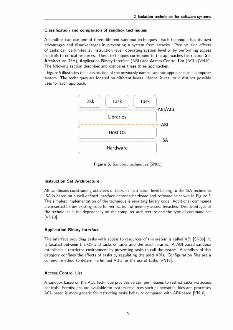
Figure 10 shows the GUI of the RCE application. It divides the user interface into differentareas which are similar to the Eclipse IDE. Users familiar with Eclipse IDE quickly learn howto use RCE. The left area shows the project explore. It may contain different projects whichcomprise of workflows and relevant other resources. The numbered areas are described in thefollowing sections.
Workflow Components
The reusable component-based approach of RCE is provided with the workflow componentswhich are an essential part for solving research problems. These components are availablethrough different sources in RCE. A set of standard components are offered by RCE whichperform fundamental functions. Some of the fundamental functionalities are parametricstudies, optimizations, input and output of data. The particular functions are mapped to the
15
3 Remote Component Environment
1
2
3
4
Figure 10: RCE instance
standard components called Parametric Study, Optimizer, Input Provider and Output Provider.These components are necessary for effective problem solving of many research questions.Components can specify various inputs and outputs. Those are necessary to exchange databetween components.
Engineers can integrate their own tools as a workflow component in RCE. These tools arecalled Integrated Tools and can be connected together with the standard components tocontribute to a solution. Additionally, tools can be platform specific which is supported bythe platform independence of RCE. Due to the distributed environment, components can bepublished within a project environment for collaboration purposes. It is extremely important forintegrated tools which may offer unique features. All workflow components available in theproject environment are contained in the palette marked with 1 in Figure 10. Componentscan be simply dragged from the palette and dropped into the so-called Workflow marked withnumber 2.
Extension features of RCE are offered through the integration of own tools. In addition,users can develop new features in form of Python scripts. Those scripts can be executed inthe standard Script component to contribute to the final result. The execution of scripts isperformed either with Python or Jython. To interact with other components, it can processinput and output values. Workflow components are an essential part of a Workflow.
16

3 Remote Component Environment
Workflow Engine
A Workflow is the basis for the simulation of complex systems. A workflow describes theconnection of workflow components for collaborative analysis or calculations. Users can createworkflows, based on their knowledge, using local, integrated or published tools to solve acurrent research problem. Furthermore, they can share their know-how by integrating owntools and offer them in the distributed environment. The Workflow engine of RCE supportsthe tool integration and monitors workflows. During the execution of a workflow, the actualtool calculation remains at the published RCE instance. Therefore, a workflow containing localand remote components only exchanges data between the components.
Workflow components can be connected together to create a workflow in the WorkflowEditor provided by RCE. The editor is located in the middle of figure 10. It show a sampleworkflow with three components marked with number 2. The connection between componentsis represented by an arrow. Additionally, it shows the data flow direction. A workflow can beexecuted by pushing the green arrow indicated with number 3 in Figure 10. A configurationdialog is prompted for the user. The user can individually select the RCE instances to managethe workflow and to run the calculation of each component contained in the workflow. Figure 11shows the configuration dialog.
1
2
3
Figure 11: Example workflow execution
17

3 Remote Component Environment
Data Management
The execution of research tasks usually generate a great amount of data. All participants in theresearch provide their data in the distributed environment. The availability and consistency ofall research data is an important factor to ensure correct and plausible results. RCE producesvarious types of data such as simulation results of an optimization or a new airplane design.The data management component provides the storage and retrieval of data. The user interfaceof RCE provides the user with access to the generated data.
The data management follows a decentralized approach and thus, each instance has its localdata store. The data store is accessible from any instance within the project environment. Duringthe examination of contributed data, the user accesses the decentralized data management asa whole rather than navigating through several data stores. All workflow components storeaccumulated data to the data management.
Distribution
To support the distributed environment feature, RCE can be configured both as a client andserver instance. Multiple instances can be connected within a network to create a commonproject environment. A user can use the client instance for creating workflows or to integrateself-developed tools. A server instance has two different deployment scenarios known as Tool-Server and Compute-Nodes. A tool server offers workflow components, specially integratedtools, inside the network. In particular time-consuming or computational-expensive workflowsor components can be executed on a compute node. Hence, the client instance is available forfurther tasks.
A RCE network can be deployed without necessary adjustments to the RCE system. However,RCE can be configured to met specific network requirements. Figure 10 shows the NetworkView marked with number 4. New connections to RCE instances, which are within the network,can be added in the network view. Additionally, it displays the current connections of theinstance. The example project environment of Figure 10 contains three instances and one ofthose is the local instance. RCE can be executed with and without the GUI. Usually, a serverinstance is started without the GUI and can be controlled via command console.
Instances can publish any workflow components, thus including the integrated tools andstandard components. In addition, a RCE instance can make itself available for other instancesas a Workflow Host. The workflow host is responsible for the execution of the workflows. Theworkflow can either be managed by the local or a selected remote instance. A remote workflowhost has a further advantage. The client instance is unoccupied of the workflow execution, thusit can be turned off or be used for other activities. During the execution, the current progresscan be looked up by connecting to the remote instance. All accumulated data are availableduring and after the execution in the data management.
In the example project environment, the two other instances are providing themselves asworkflow hosts. At each workflow start, the target host can be selected as marked with 2 inFigure 11. Number 3 highlights the possible selection of instances which provide the workflowcomponent contained in the workflow. In the example, the component Input Provider iscontributed by a remote instance [SFL+12].
18

3 Remote Component Environment
3.2 Application area of RCE
Initially, RCE was implemented for the shipyard industry. The reusable component-basedapproach of RCE makes it possible to use it for different areas. Two of those areas are space-and aircraft and for each area a real world example is described.
The first real world example is called Virtual Satellite and is an application for the spacecraftindustry. It is intended to support the national satellite program. It started as an Eclipse RCPapplication and RCE was later integrated. The main purpose of the application is to designsatellites [SFL+12].
Chameleon is a specific environment for exploratory aircraft design. The project objectiveswere to simulate new aircraft designs in a collaborative environment with various experts. As aresult, it needed a distributed design environment and was implemented on top of RCE reusingits software components. TIGLViewer was integrated for visualizing the aircraft geometry.Chameleon focuses on aeronautic specific components build on Common Parametric AircraftConfiguration Scheme (CPACS). CPACS is a special XML data format designed for theexchange of input and output data between components [SFL+12].
3.3 Relevance of isolation techniques for RCE
The RCE framework is composed of a component-based and extensible software architecture.A disadvantage for those architectures are security risks involving the execution of remotecode. The implementation of an appropriate security management should consider the followingfactors: managing permissions by establishing a security policy, establishing identities, enforcingaccess controls and managing user privileges [HPMS11].
The JVM provides RCE with full access to the system resources. Therefore, the wholeframework including workflow components have unrestricted access. Several reasons arise toconsider isolation techniques for RCE. Firstly, RCE uses a component-based approach. Theworkflow components might harm the underlying system. For example, the Output Providercould store large amount of data files in unauthorized directories. It can result in filling upall storage space of the system which may abruptly interrupt other workflow executions. TheScript component is another possible way to harm the system. Programmed python scriptsmight either contain programming errors or being intentionally malicious. Due to the full accessprovided to the script component, the script may damage the system.
The distributed approach is another reason for considering isolation techniques to protect thehost system. Publishing workflow components is a security risk, because the actual calculationstays at the published instance. For this reason, it is currently advised against publishing thescript component. Integrated tools can basically contain malicious code, but the effect islimited to the published instance. Under the circumstances shown above, workflow componentsand especially developed python scripts can be classified as remote code. Consequently, theconsideration of an isolation technique preventing possible damage by components is appropriate.
The isolation technique should be incorporated into RCE to ensure the maintainability andto guarantee the isolation is active. The access permissions of RCE should be limited andonly the most necessary permissions should be allowed. Additionally, the technique should beextensible for future requirements. RCE is programmed with Java which ships with a build-insandbox model. Hence, sandboxing should be considered for increasing the overall security ofthe RCE framework by restricting access to resources. The sandbox prototype should considerto implement security policies and to perform access controls.
19

4 Development of a sandbox prototype forRCE
The objective of this thesis is the design and implementation of a sandbox prototype for securingRCE. Firstly, this chapter describes the requirement analysis starting with the stakeholderanalysis followed by the raised user stories. The sandbox model illustration of Java and OSGiare necessary for the prototype implementation. Hereafter, the elements requesting access tosystem resources are identified. The classification of the sandbox prototype for RCE is basedon the specifications of the sandbox model of Java or rather OSGi. Subsequently, the designand implementation is described which puts everything named above together to succeed theobjective. Finally, the framework architecture is explained with the new security layer andpossible future extensions.
The following font is used for the names of Java classes, interfaces, methods andkeywords within the following section.
4.1 Requirements analysis
The stakeholder and requirements for the sandbox prototype are determined for the ongoingimplementation. The stakeholder analysis is performed to identify roles which are affectedby the prototype. The three roles Developer, User and Administrator are determined andillustrated in Table 3.
Stakeholder RoleDeveloper specifies the maximum permissions of a bundle
User uses a RCE instance for designing and executingworkflows
Administrator manages permissions of a RCE instance
Table 3: Stakeholder
Developers enhance existing features and implement new requirements. They are responsiblefor the bundles comprising all features of RCE. The user role represents scientists and engineerswho are using RCE to solve research questions. The user is capable of designing and executinglocal and remote workflows. In addition, users can integrate self programmed tools and publishthose in the project environment. Sandbox prototype introduces an administrator as a newrole to manage the permissions for a RCE instance. Users are only assigned the administratorrole for its own instance. During a remote workflow execution the user is not obligated tomake permission decisions. Hence, a administrator is responsible for permission managementof the remote instance. Division of responsibilities between user and administrator role ensuresappropriate management of permissions.
The user benefits from the sandbox prototype. The prototype is implemented in order toreduce the vulnerability of the system. The developer has to contribute to achieve the objectiveof securing RCE. In particular, the developer is responsible to assign the appropriate permissionsto a bundle of RCE. As a result, the developer should obtain professional knowledge about thepermission concept of the Java sandbox model. The prototype has less influence on the user.Only the execution of a workflow can be affected. In other words, the user is not faced withpermission decisions during workflow execution. Accordingly, denied permissions result in afailed workflow execution.
20
4 Development of a sandbox prototype for RCE
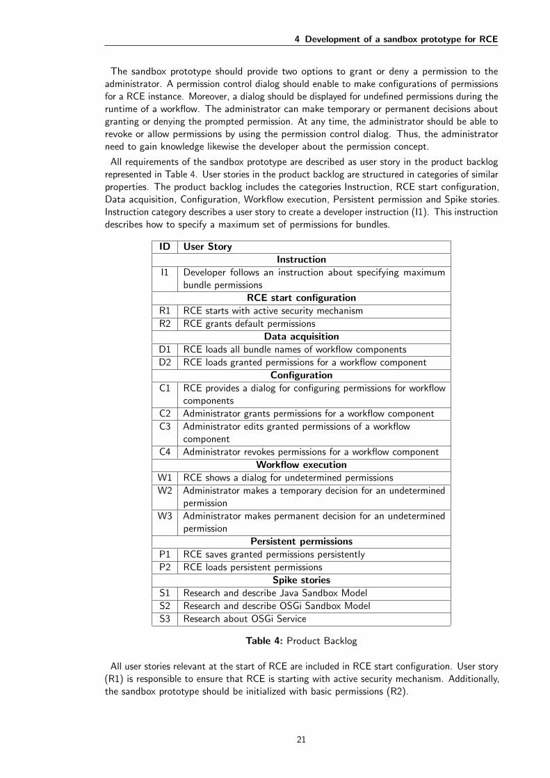
The sandbox prototype should provide two options to grant or deny a permission to theadministrator. A permission control dialog should enable to make configurations of permissionsfor a RCE instance. Moreover, a dialog should be displayed for undefined permissions during theruntime of a workflow. The administrator can make temporary or permanent decisions aboutgranting or denying the prompted permission. At any time, the administrator should be able torevoke or allow permissions by using the permission control dialog. Thus, the administratorneed to gain knowledge likewise the developer about the permission concept.
All requirements of the sandbox prototype are described as user story in the product backlogrepresented in Table 4. User stories in the product backlog are structured in categories of similarproperties. The product backlog includes the categories Instruction, RCE start configuration,Data acquisition, Configuration, Workflow execution, Persistent permission and Spike stories.Instruction category describes a user story to create a developer instruction (I1). This instructiondescribes how to specify a maximum set of permissions for bundles.
ID User StoryInstruction
I1 Developer follows an instruction about specifying maximumbundle permissions
RCE start configurationR1 RCE starts with active security mechanism
R2 RCE grants default permissions
Data acquisitionD1 RCE loads all bundle names of workflow components
D2 RCE loads granted permissions for a workflow component
ConfigurationC1 RCE provides a dialog for configuring permissions for workflow
components
C2 Administrator grants permissions for a workflow component
C3 Administrator edits granted permissions of a workflowcomponent
C4 Administrator revokes permissions for a workflow component
Workflow executionW1 RCE shows a dialog for undetermined permissions
W2 Administrator makes a temporary decision for an undeterminedpermission
W3 Administrator makes permanent decision for an undeterminedpermission
Persistent permissionsP1 RCE saves granted permissions persistently
P2 RCE loads persistent permissions
Spike storiesS1 Research and describe Java Sandbox Model
S2 Research and describe OSGi Sandbox Model
S3 Research about OSGi Service
Table 4: Product Backlog
All user stories relevant at the start of RCE are included in RCE start configuration. User story(R1) is responsible to ensure that RCE is starting with active security mechanism. Additionally,the sandbox prototype should be initialized with basic permissions (R2).
21

4 Development of a sandbox prototype for RCE
Functionalities described in the Data acquisition category provide essential data for managingpermissions through the configuration dialog (D1-D2). The sandbox prototype should realize adialog for the management of permissions by the administrator (C1). An administrator shouldbe able to allow and deny permissions for each workflow component (C2-C4). The dialogshould be accessible at any time during the runtime of RCE.
During a workflow execution, undetermined permissions may be requested by a workflowcomponent. The category Workflow execution includes user stories which provide feedback tothe administrator. An approval and disapproval dialog is shown with the workflow componentname and the requested permission (W1). The administrator should be able to make temporaryor permanent decisions about allowing or denying the permission (W2-W3). Temporary meansthat the components gains the permission only for one access. Hence, the dialog may appearseveral times. On the other hand, the permanent decision prevents the dialog to reappear. Apermanent allowed decision should be accessible and changeable through configuration dialogdescribed above.
Granted permissions by the administrator should be stored persistently (P1) and loaded (P2)at RCE start. The prototype can work without these features. However, a restart resets allgranted permissions.
The product backlog also includes Spike stories (S1-S3). Spike stories are intended to acquireessential technical knowledge. The prototype implementation requires knowledge about theJava and OSGi sandbox model (S1-S2). Both sandbox models are described in the followingsection. Knowledge about OSGi services is helpful for using existing services such as the CPAS(S3). Additionally, it can be useful for providing an own service to manage the permissions inRCE.
ID of User Story/ Precondition
I1
R1
R2
D1
D2
C1
C2
C3
W1
W2
W3
P1
P2
S1
S2
S3
I1 X X
R1 X X
R2 X X X
D1 X
D2 X X X X
C1 X X X X X X
C2 X X X X X
C3 X X X X X
C4 X X X X X
W1 X X X X
W2 X X X X
W3 X X X X
P1 X X
P2 X X
S1
S2 X
S3
Table 5: Traceability matrix
The Traceability matrix in Table 5 shows the dependencies between the user stories from theproduct backlog. The rows represent the user stories and the columns contain user storiesclassified as preconditions. The user stories are put in relation to identify required preconditions.A dependency between a user story and a precondition is visualized by an X. A user story with
22

4 Development of a sandbox prototype for RCE
preconditions can only be implemented when all preconditions are fulfilled. The processingorder of the requirements is determined based on the user stories priority and dependencies.
In addition to the requirements described in the product backlog, the following requirementsneed to be considered during the implementation of the prototype. Firstly, the prototypeshould meet the quality requirements including security improvements while providing good userexperience. The general purpose of the sandbox prototype is to improve the overall securityof RCE. To maintain a good user experience, the prototype should prefer to ask for missingpermission rather than terminating a running workflow. Following technical requirements arenecessary regarding design and implementation of the prototype. RCE is implemented in Java.Therefore, the prototype should be developed with Java. Table 6 contains technical key datarelevant for the prototype development. Java Development Kit (JDK) 1.7 is used for thedevelopment. However, RCE is executable on Java above 1.7 including the latest version 1.8.In addition, separate bundles should be created for structuring the source code. Furthermore,the prototype should be implemented without modifying existing bundles. Modification ofexisting code is only allowed for activating and initializing of the sandbox prototype. Finally,RCE is open source and thus, the prototype source code must comply the Eclipse PublicLicense (EPL).
RCE Version 7.1.0
RCP Version 3.7.2
OSGi Version 4.3
Java JDK 1.7
Table 6: Technical key data of the RCE framework
4.1.1 Usability of security
The user and particularly the usability have influence on the security of software applications.Developers should include the user as part of the security chain [WT98]. The terms Usabilityand User Experience are becoming more important for developers to consider in the design ofsecure applications. Usability refers to the user-friendliness and intuitive use of a product. Fora software application, a well thought-out user interface is important for a great usability. Theappearance of a product is not the focus of the user experience, but rather the interactionbetween user and a product [ISO06, ISO10]. In the following section, both terms are describedregarding software applications.
Usability and user experience
Usability is a quality feature of a product. An easily and intuitively usable product has awell designed usability. The usability of a software application depends on the context of use.Especially for different interaction options with the application such as mouse, keyboard, touchor even movement. Usability is defined as a result of effectiveness, efficiency and satisfaction[ISO06].
The term user experience appears often in connection with usability. It describes all aspects ofthe experience of a user interacting with a system. The term is defined for software applicationin the norm EN ISO 9241-210 as follows: The awareness and reaction of a user as a result ofthe expected use of a product. In addition, the norm differentiates the terms user experienceand usability. Accordingly, user experience includes all effects to the user which a productalready has before and after the usage. On the other hand, usability has the focus on the actual
23

4 Development of a sandbox prototype for RCE
usage [ISO10]. Usability of security is explained based on a study about the usability of theJava policy tool.
4.1.2 Usability of the Java policy tool
The access control of Java is defined by external policy files containing specified permissions.Those files setup by the user or administrator. Accordingly, Java provides a graphical policytool for creating and managing those policy files. The security policy creation is complicatedand error-prone and thus security-critical. The study [HS06] shows that managing the policyfiles with the policy tool is inefficient and difficult for users. As a result, the users had problemswith the graphical user interface of the policy tool. Furthermore, user generated policy filesshowed different content [HS06].
In other words, the security of applications can be enhanced by focusing more strongly on theusability. The study [WT98] proposes suggestions for solving problems with the usability toimprove the security. A high priority for the security is a good designed user interface. The usershould be guided through an application to learn and understand all security aspects. Securitychecks should be designed discreet. The creation and managing process of security policiesshould be intuitive for the user. The application should provide good feedback to the useravoiding dangerous errors produced by a user [WT98].
To summarize, the following usability keywords of the ISO standard 9241-11 are used toconnect the problems of the policy tool with the proposed suggestions for usability: Effectiveness,Efficiency and User satisfaction [ISO98]. Firstly, Effectiveness means active support for theuser during the use of an application. The support can be implemented by providing wizards toguide the user. These complies with the guidance suggestion of the study [WT98]. A wizardcan be useful for the Java policy tool to train and guide novice users through the creationprocess. However, the Java policy tool might be helpful for users with advanced knowledgeabout Java security mechanisms.
Secondly, the achievement of a task measured by the use of resources such as a computerand a user is described by efficiency. Efficiency can be distinguished by the user knowledge.A novice user accomplishes a task more efficient with provided guidance and help functions.On the other hand, the efficiency of an advanced user can be increased by keyboard shortcutsto navigate through the GUI. The user fails to operate the Java policy tool. The policy filecreation requires a lot of effort to figure out the necessary steps. Nevertheless, the policy tooldoes not provide any help functionalities.
Finally, the user satisfaction describes the acceptance of an application by the users. Theacceptance can be improved by a good designed user interface. In addition, a rewarding orfun experience during the interaction with an application promotes the acceptance. The Javapolicy tool could increase the acceptance by being integrated into the Java runtime. For thepurpose of collecting necessary permissions and the user reacts to allow or deny a permission.
In conclusion, usability and user experience are important aspects to be considered for thesandbox in RCE. The sandbox prototype should involve the administrator for securing the RCEsystem.
24
4 Development of a sandbox prototype for RCE
4.2 Overview of the Java Security model
The sandbox prototype for RCE is supposed to work seamlessly with the underlying framework.In this case, Java introduced a sandbox model. OSGi adds additional features to the existingJava model. Both frameworks provide APIs for accessing and extending the sandbox model tomeet the needed requirements. The following subsection describes Java sandbox model (S1).It covers the evolution of the sandbox model from the first version in JDK 1.0.x to the latestversion in JDK 1.2. Additionally, implementations of essential Java classes and interfaces aredescribed and the interaction is illustrated.
The connection between the Java and OSGi sandbox model is described in subsection 4.2.2(S2). Moreover, additional features added by OSGi are introduced such as the conditionconcept. OSGi provides Permission Admin Service (PAS) and Conditional Permission AdminService (CPAS) for managing the application permissions. Those services are explained in moredetail. The relevant Java classes and interfaces are reused in the design and implementation ofthe actual prototype.
4.2.1 Java Sandbox model
The Java sandbox was introduced by Java as a playground for executing external programsin JDK 1.0.x. Those programs received only limited access to available resources, the systemresources. The general purpose of the sandbox is to constrain programs within its boundaries.The sandbox has the responsibility to protect certain resources of the system. Java applicationshave access to resources of the host system like local memory, file system, private network andthe internet.
The first sandbox model was designed specially for securely executing Java Applets. A Javaapplet is a program executed within a web browser and it may be published on the internetfrom an untrusted source. Therefore, it is confined during the execution in the sandbox ofJava. Since the latest sandbox model of JDK 1.2, all Java applications are able to run within asandbox. The same security concept is used for applets and other applications. Nevertheless,applets are always executed with the sandbox. For normal Java applications the sandbox needsto be activated explicitly.
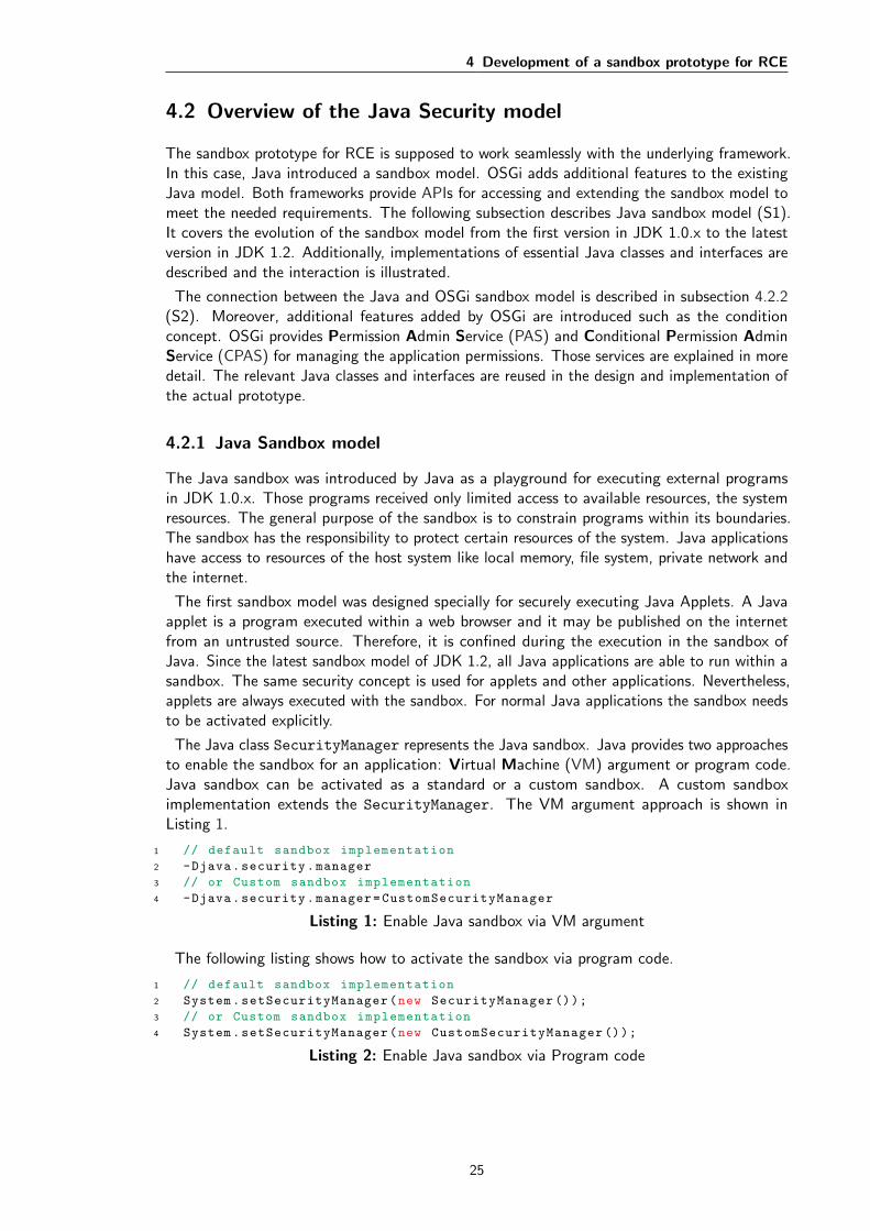
The Java class SecurityManager represents the Java sandbox. Java provides two approachesto enable the sandbox for an application: Virtual Machine (VM) argument or program code.Java sandbox can be activated as a standard or a custom sandbox. A custom sandboximplementation extends the SecurityManager. The VM argument approach is shown inListing 1.
1 // default sandbox implementation
2 -Djava.security.manager
3 // or Custom sandbox implementation
4 -Djava.security.manager=CustomSecurityManager
Listing 1: Enable Java sandbox via VM argument
The following listing shows how to activate the sandbox via program code.
1 // default sandbox implementation
2 System.setSecurityManager(new SecurityManager ());
3 // or Custom sandbox implementation
4 System.setSecurityManager(new CustomSecurityManager ());
Listing 2: Enable Java sandbox via Program code
25
4 Development of a sandbox prototype for RCE
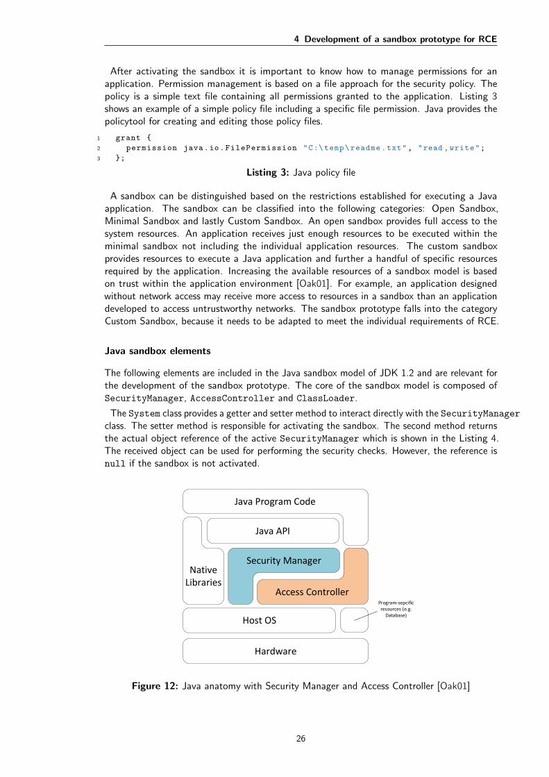
After activating the sandbox it is important to know how to manage permissions for anapplication. Permission management is based on a file approach for the security policy. Thepolicy is a simple text file containing all permissions granted to the application. Listing 3shows an example of a simple policy file including a specific file permission. Java provides thepolicytool for creating and editing those policy files.
1 grant {
2 permission java.io.FilePermission "C:\temp\readme.txt", "read ,write";
3 };
Listing 3: Java policy file
A sandbox can be distinguished based on the restrictions established for executing a Javaapplication. The sandbox can be classified into the following categories: Open Sandbox,Minimal Sandbox and lastly Custom Sandbox. An open sandbox provides full access to thesystem resources. An application receives just enough resources to be executed within theminimal sandbox not including the individual application resources. The custom sandboxprovides resources to execute a Java application and further a handful of specific resourcesrequired by the application. Increasing the available resources of a sandbox model is basedon trust within the application environment [Oak01]. For example, an application designedwithout network access may receive more access to resources in a sandbox than an applicationdeveloped to access untrustworthy networks. The sandbox prototype falls into the categoryCustom Sandbox, because it needs to be adapted to meet the individual requirements of RCE.
Java sandbox elements
The following elements are included in the Java sandbox model of JDK 1.2 and are relevant forthe development of the sandbox prototype. The core of the sandbox model is composed ofSecurityManager, AccessController and ClassLoader.
The System class provides a getter and setter method to interact directly with the SecurityManagerclass. The setter method is responsible for activating the sandbox. The second method returnsthe actual object reference of the active SecurityManager which is shown in the Listing 4.The received object can be used for performing the security checks. However, the reference isnull if the sandbox is not activated.
Hardware
Host OS
Program-sepcific resources (e.g.
Database)
Access Controller
Security Manager
Java Program Code
Java API
Native Libraries
Figure 12: Java anatomy with Security Manager and Access Controller [Oak01]
26

4 Development of a sandbox prototype for RCE
The general purpose of the SecurityManager is to decide whether a security-related func-tion should be granted access to a particular resource. The application’s security policy ismanaged by the SecurityManager. The AccessController has the same purpose andwas introduced in JDK 1.2. The SecurityManager delegates all security checks to theAccessController. Hence, the SecurityManager is supplemented with the introduction ofthe AccessController. Figure 12 shows the interaction of both classes.
A normal function call started in the Java program code accesses a function provided by theJava API. For security-related functions the SecurityManager is informed which delegates thecall to the AccessController. It is decided based on the security policy to grant or deny theresource access. A granted call finally accesses the operating system. Whereas, a denied callproduces an exception and is not forwarded to the operating system. The SecurityManager
may ignore the AccessController in special cases.
Listing 4 illustrates the general approach of performing security critical methods. Firstly, amethod verifies that the SecurityManager is installed. Hereafter, it can perform securitycalls using the security manager. The security manager throws an exception if the access isdenied. Hence, the ongoing method call is interrupted by the exception. Otherwise, the methodperforms the actual operation [Oak01].
1 public int length(String fileName) {
2 SecurityManager securityManager = System.getSecurityManager ();
3 if (securityManager != null) {
4 // perform security checks only if the SecurityManager is present
5 securityManager.checkRead(fileName);
6 }
7 int length;
8 // method code goes here
9 return length;
10 }
Listing 4: Performing security check
Permission class encapsulates an operation request to a specific resource. Permission
represents the basis class and Java provides several standard permissions in the Java API.For example, Java API contains the AllPermission class to grant access to all resourcesand a specific permission representing the file resource which is called FilePermission. Thepermission type, name and actions are the key elements of a permission object.
The example policy file in Listing 3 contains a permission entry. Each permission entry inthe policy file starts with ”permission” and ends with a semicolon. The key elements of apermission declared after ”permission” in the following order: type, name and actions. Theexample shows a permission for the file readme.txt with read and write access. The declarationof the name and action can be left out for the AllPermission. The permission object is usedfor two different purposes. Firstly, a permission can be assigned to a class which grants theclass to access the resource represented by the permission. Secondly, the AccessController
makes a decision based on a permission object to allow or deny the call of an operation.
The ClassLoader is responsible for loading necessary Java classes during the execution ofa Java application. Additionally, it determines a set of permissions for the loaded class. AProtectionDomain is constructed for the location of a loaded class. The protection domaincontains all granted permissions for the specific location. During a security check for a particularpermission the AccessController examines all active protection domains on the stack to bein possession of the permission to continue the method call [Oak01].
The above described elements of the sandbox model are illustrated in Figure 28. The figureshows the interactions between the Java classes composing the sandbox model. A summary ofthe Java classes and interfaces is described in Table 9.
27
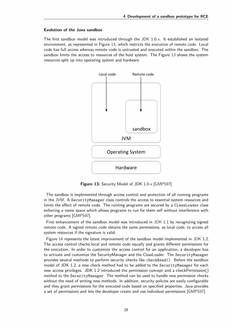
4 Development of a sandbox prototype for RCE
Evolution of the Java sandbox
The first sandbox model was introduced through the JDK 1.0.x. It established an isolatedenvironment, as represented in Figure 13, which restricts the execution of remote code. Localcode has full access whereas remote code is untrusted and executed within the sandbox. Thesandbox limits the access to resources of the host system. The Figure 13 shows the systemresources split up into operating system and hardware.
Local code Remote code
Hardware
Operating System
JVM
sandbox
Figure 13: Security Model of JDK 1.0.x [GMPS97]
The sandbox is implemented through access control and protection of all running programsin the JVM. A SecurityManager class controls the access to essential system resources andlimits the effect of remote code. The running programs are secured by a ClassLoader classenforcing a name space which allows programs to run for them self without interference withother programs [GMPS97].
First enhancement of the sandbox model was introduced in JDK 1.1 by recognizing signedremote code. A signed remote code obtains the same permissions, as local code, to access allsystem resources if the signature is valid.
Figure 14 represents the latest improvement of the sandbox model implemented in JDK 1.2.The access control checks local and remote code equally and grants different permissions forthe execution. In order to customize the access control for an application, a developer hasto activate and customize the SecurityManager and the ClassLoader. The SecurityManager
provides several methods to perform security checks like checkRead(). Before the sandboxmodel of JDK 1.2, a new check method had to be added to the SecurityManager for eachnew access privileges. JDK 1.2 introduced the permission concept and a checkPermission()method to the SecurityManager. The method can be used to handle new permission checkswithout the need of writing new methods. In addition, security policies are easily configurableand they grant permissions for the executed code based on specified properties. Java providesa set of permissions and lets the developer create and use individual permissions [GMPS97].
28
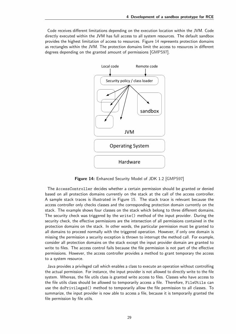
4 Development of a sandbox prototype for RCE
Code receives different limitations depending on the execution location within the JVM. Codedirectly executed within the JVM has full access to all system resources. The default sandboxprovides the highest limitation of access to resources. Figure 14 represents protection domainsas rectangles within the JVM. The protection domains limit the access to resources in differentdegrees depending on the granted amount of permissions [GMPS97].
Local code Remote code
Hardware
Operating System
JVM
sandbox
Security policy / class loader
Figure 14: Enhanced Security Model of JDK 1.2 [GMPS97]
The AccessController decides whether a certain permission should be granted or deniedbased on all protection domains currently on the stack at the call of the access controller.A sample stack traces is illustrated in Figure 15. The stack trace is relevant because theaccess controller only checks classes and the corresponding protection domain currently on thestack. The example shows four classes on the stack which belong to three different domains.The security check was triggered by the write() method of the input provider. During thesecurity check, the effective permissions are the intersection of all permissions contained in theprotection domains on the stack. In other words, the particular permission must be granted toall domains to proceed normally with the triggered operation. However, if only one domain ismissing the permission a security exception is thrown to interrupt the method call. For example,consider all protection domains on the stack except the input provider domain are granted towrite to files. The access control fails because the file permission is not part of the effectivepermissions. However, the access controller provides a method to grant temporary the accessto a system resource.
Java provides a privileged call which enables a class to execute an operation without controllingthe actual permission. For instance, the input provider is not allowed to directly write to the filesystem. Whereas, the file utils class is granted write access to files. Classes who have access tothe file utils class should be allowed to temporarily access a file. Therefore, FileUtils canuse the doPrivileged() method to temporarily allow the file permission to all classes. Tosummarize, the input provider is now able to access a file, because it is temporarily granted thefile permission by file utils.
29

4 Development of a sandbox prototype for RCE
InputProvider.write()
FileUtils.write()
new FileOutputStream()
AccessController.checkPermission()
Stack trace Protection Domain
IP Domain
Utils Domain
System Domain
System Domain
Permissions
Permissions
Permissions
Permissions
=
Effective Permissions
Figure 15: Stack trace during a security check [Oak01]
4.2.2 Security in Eclipse Equniox/OSGi
The Java 2 sandbox model forms the basis for the sandbox model of the OSGi framework. OSGiprovides an extensible and comprehensive sandbox model to be easily adaptable for securingapplications. Eclipse Equinox implements the OSGi specification and developers can takeadvantage of the Java and OSGi sandbox model to secure their RCP applications [HPMS11].
OSGi established the bundle concept for reusable functionalities of loose modules. Thefile-based approach of the Java sandbox model is unsuitable for managing security policies atbundle level. Therefore, OSGi introduced two framework services called Permission AdminService (PAS) and Conditional Permission Admin Service (CPAS). Those services provideAPIs for permission management at the bundle level which is more suitable for the modularand dynamic architecture. CPAS provides the management of permissions in real time. Hence,changes to the permissions are effective without application restart.
Additionally, the Condition approach is introduced by OSGi. Security policies define permis-sions to access specific resources which can be guarded by conditions. For example, a conditioncan be based on the bundle location, bundle signature or custom conditions. It allows to grantpermissions to bundles which satisfy the conditions. The custom conditions can vary fromthe application context. A benefit of the condition approach is that a custom condition maypresent a dialog to receive an approval or decline of the user to certain permissions.
The sandbox of a RCP application is activated by installing a security manager. However,the default implementation of the security manager is insufficient. Eclipse Equinox provides acustom security manager class called EquinoxSecurityManager. To activate the sandbox, anEclipse RCP application must be started with one of the following VM arguments:
1 // Eclipse Equinox sandbox implementation
2 -Declipse.security=osgi
3 // or
4 -Declipse.security=org.eclipse.osgi.internal.permadmin.
EquinoxSecurityManager
Listing 5: Enable Eclipse sandbox
Both arguments install the EquinoxSecurityManager.
30

4 Development of a sandbox prototype for RCE
Eclipse Equinox/OSGi sandbox elements
The following description of relevant sandbox elements are included in the RCP version 3.7.2which implements OSGi in version 4.3. Hence, the elements are available in the developmentof a sandbox prototype for RCE.
The class diagram shown in Figure 16 composes all necessary classes, interfaces and theirrelationship for developing the sandbox prototype. The diagram is divided into the sandboxAPI of OSGi (upper half) and the actual implementation of Eclipse Equinox (lower half).The OSGi API classes are used to create the design of the sandbox prototype. The diagramcontains classes provided by the API of Java (orange), OSGi (blue) and Eclipse Equinox (green).Furthermore, extension options of the sandbox model are visualized by the gray classes.
<<interface>>
ConditionalPermissionAdmin
1 *has
<<interface>>
ConditionalPermissionInfo
*1has
Permission{abstract}
PermissionInfo
<<interface>>
Condition
BundleSignerCondition BundleLocationCondition
ManagerImplementation
manage
1 *has
1
*has
CustomCondition
encodes
encodes
<<interface>>
ConditionalPermissionUpdate
ConditionInfo
SecurityAdminSecurityManagerEquinoxSecurityManager
SecurityRowSnapShot
SecurityTable
BundlePermissions<<interface>>
Bundle EquinoxBundlePermissionCollection{abstract}
ProtectionDomainBundleProtectionDomain
Java
OSGi
Eclipse Equinox
OSGi sandbox API
Eclipse Equinox sandbox implementation
CustomPermission
Figure 16: UML class diagram of the Eclipse Equinox/OSGi Sandbox model [OSG11]
The core element of the sandbox model is the ConditionalPermissionAdmin service.It is part of framework services of OSGi. The general purpose of CPAS is to support amanagement implementation to enforce and control a security policy of the application. EclipseEquinox provides a concrete subclass of the services called SecurityAdmin. To work with theSecurityAdmin, the CPAS can be requested from the service registry. CPAS is initialized duringthe start up of framework. It is available independent of the installed security manager. However,the permission management is useless without security controls. EquinoxSecurityManager
should be used in connection with the CPAS.
CPAS provides an API to enforce and manage the security policy which is represented as theso-called policy table. The policy table is valid for the whole system. It is composed of policyentities. The ConditionalPermissionInfo class describes the content of a policy. The policykeeps information about the access type, conditions, permissions and a unique name. Listing 6shows example policy entries. The syntax of the policy entry starts with the access type andends with the unique name. The conditions and permissions are specified inside of the curlybrackets. Each condition is encoded within square brackets and each permission within round
31
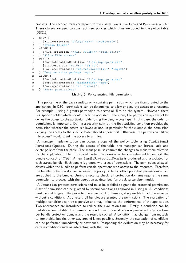
4 Development of a sandbox prototype for RCE
brackets. The encoded form correspond to the classes ConditionInfo and PermissionInfo.These classes are used to construct new policies which than are added to the policy table.[OSG11]
1 DENY {
2 (FilePermission "C:\ System \*" "read ,write")
3 } "System folder"
4 ALLOW {
5 (FilePermission "<<ALL FILES >>" "read ,write")
6 } "Allow File access"
7 DENY {
8 [BundleLocationCondition "file:inputprovider"]
9 [TimeCondition "before" "11:30"]
10 (PackagePermission "de.rce.security .*" "import")
11 } "Deny security package import"
12 ALLOW {
13 [BundleLocationCondition "file:inputprovider"]
14 (ServicePermission "LogService" "get")
15 (PackagePermission "*" "import")
16 } "Basic permissions"
Listing 6: Policy entries: File permissions
The policy file of the Java sandbox only contains permission which are than granted to theapplication. In OSGi, permissions can be determined to allow or deny the access to a resource.For example, Listing 6 grants permission to access all files on the system. However, thereis a specific folder which should never be accessed. Therefore, the permission system folderdenies the access to the particular folder using the deny access type. In this case, the order ofpermissions is important. During a security control, the first satisfied condition provides thepermission whether the access is allowed or not. In particular for the example, the permissiondenying the access to the specific folder should appear first. Otherwise, the permission ”AllowFile access” would grant the access to all files.
A manager implementation can access a copy of the policy table using Conditional
PermissionUpdate. During the access of the table, the manager can iterate, add anddelete policies from the table. The manage must commit the changes to make them effectivefor the application. The introduced protection domain in Java is extended to support thebundle concept of OSGi. A new BundleProtectionDomain is produced and associated foreach started bundle. Each bundle is granted with a set of permissions. The permissions allow allclasses within the bundle to perform certain operations with access to the resources. Therefore,the bundle protection domain accesses the policy table to collect potential permissions whichare applied to the bundle. During a security check, all protection domains require the samepermission to proceed with the operation as described for the Java sandbox model.
A Condition protects permissions and must be satisfied to grant the protected permissions.A set of permission can be guarded by several conditions as showed in Listing 6. All conditionsmust be met to grant the protected permissions. Furthermore, it is possible to add permissionswithout a conditions. As a result, all bundles are granted the permissions. The evaluation ofmultiple conditions can be expensive and may influence the performance of the application.Two approaches are introduced to reduce the evaluation time. Firstly, a condition can bemutable or immutable. For immutable conditions, the evaluation is proceeded only one timeper bundle protection domain and the result is cached. A condition may change from mutableto immutable, but the other way around is not possible. Secondly, the evaluation of conditionscan be performed immediately or postponed. Postponing the evaluation may be necessary forcertain conditions such as interacting with the user.
32
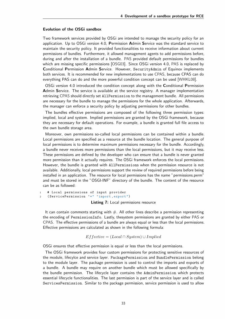
4 Development of a sandbox prototype for RCE
Evolution of the OSGi sandbox
Two framework services provided by OSGi are intended to manage the security policy for anapplication. Up to OSGi version 4.0, Permission Admin Service was the standard service tomaintain the security policy. It provided functionalities to receive information about currentpermissions of bundles. Furthermore, it allowed management agents to add permissions before,during and after the installation of a bundle. PAS provided default permissions for bundleswhich are missing specific permissions [OSG03]. Since OSGi version 4.0, PAS is replaced byConditional Permission Admin Service. However, SecurityAdmin of Equinox implementsboth services. It is recommended for new implementations to use CPAS, because CPAS can doeverything PAS can do and the more powerful condition concept can be used [WHKL08].
OSGi version 4.0 introduced the condition concept along with the Conditional PermissionAdmin Service. The service is available at the service registry. A manager implementationretrieving CPAS should directly set AllPermission to the management bundle. All permissionsare necessary for the bundle to manage the permissions for the whole application. Afterwards,the manager can enforce a security policy by adjusting permissions for other bundles.
The bundles effective permissions are composed of the following three permission types:implied, local and system. Implied permissions are granted by the OSGi framework, becausethey are necessary for default operations. For example, a bundle is granted full file access tothe own bundle storage area.
Moreover, own permissions so-called local permissions can be contained within a bundle.Local permissions are specified as a resource at the bundle location. The general purpose oflocal permissions is to determine maximum permissions necessary for the bundle. Accordingly,a bundle never receives more permissions than the local permissions, but it may receive less.These permissions are defined by the developer who can ensure that a bundle is never grantedmore permission than it actually requires. The OSGi framework enforces the local permissions.However, the bundle is granted with AllPermissions when the permission resource is notavailable. Additionally, local permissions support the review of required permissions before beinginstalled in an application. The resource for local permissions has the name ”permissions.perm”and must be stored in the ”OSGI-INF” directory of the bundle. The content of the resourcecan be as followed:
1 # Local permissions of input provider
2 (ServicePermission "*" "import ,export")
Listing 7: Local permissions resource
It can contain comments starting with #. All other lines describe a permission representingthe encoding of PermissionInfo. Lastly, thesystem permissions are granted by either PAS orCPAS. The effective permissions of a bundle are always equal or less than the local permissions.Effective permissions are calculated as shown in the following formula:
Effective = (Local ∩ System) ∪ Implied
OSGi ensures that effective permission is equal or less than the local permissions.
The OSGi framework provides four custom permissions for protecting sensitive resources ofthe module, lifecylce and service layer. PackagePermission and BundlePermission belongto the module layer. The package permission is used to control the imports and exports ofa bundle. A bundle may require on another bundle which must be allowed specifically bythe bundle permission. The lifecycle layer contains the AdminPermission which protectsessential lifecycle functionalities. The last permission is part of the service layer and is calledServicesPermission. Similar to the package permission, service permission is used to allow
33

4 Development of a sandbox prototype for RCE
a bundle to register or receive a service.
The introduced condition concept is very powerful for managing permissions. OSGi providestwo default conditions to grant permission based on the bundle location and the bundle signer.Additionally, it provides a developer to create custom conditions to efficiently enforce thesecurity policy. To eliminate all security-risks, all conditions are loaded from the frameworkclass path. Thus, the bundle of a custom condition must be available for the system bundle:Fragment-Host: system.bundle; extension:=framework
Such an extension include limitations for the condition bundle, because it is not allowed toimport or require other bundles. The implementation of a condition is limited to the Java andEclipse Equinox API. For example, a user dialog can not be programmed with Standard WidgetToolkit, because it requires the import of another bundle. A custom condition implements theCondition interface and it needs to provide the following constructor or static method:
1 public class CustomCondition implements Condition {
2 public CustomCondition(Bundle b, ConditionInfo i) {}
3 public static Condition getCondition(Bundle b, ConditionInfo i){
4 // return instance
5 }
6 }
Listing 8: Custom condition [HPMS11]
The class diagram in Figure 16 describes the static relationship between the elements composingthe sandbox model. Figure 17 provides an example of the interaction of elements during anaccess control of a RCP application. Usually, a security check is triggered through a call to theinstalled security manager. In this case, the EquinoxSecurityManager performs a privilegedcall, thus triggers the internal check. The internal check passes on the permission check to theAccessControlContext.
During the check, the context has access to all available protection domains on the stack.In particular, the protection domains are represented by BundleProtectionDomains. Alldomains are verified in a loop that the permission is granted or can be implied from otherpermissions. The implied permissions provided by the framework are reviewed first withinBundlePermissions. Eventually, SecurityAdmin verifies the permission against local andsystem permissions. Accordingly, the checked permission is either implied by the effectivepermissions or a security exception is thrown. In the case that the permission can be implied,the security manager continues to loop through all postponed conditions. A security exceptionmay be caused, if only one condition can not be satisfied. Otherwise, the operation whichtriggered the security check is granted to access the sensitive resource.
To summarize, all essential concepts and elements of both sandbox models are described.Therefore, the spike stories (S1-S2) are successful performed and provides an excellent foundationfor the design and implementation of the sandbox prototype.
34
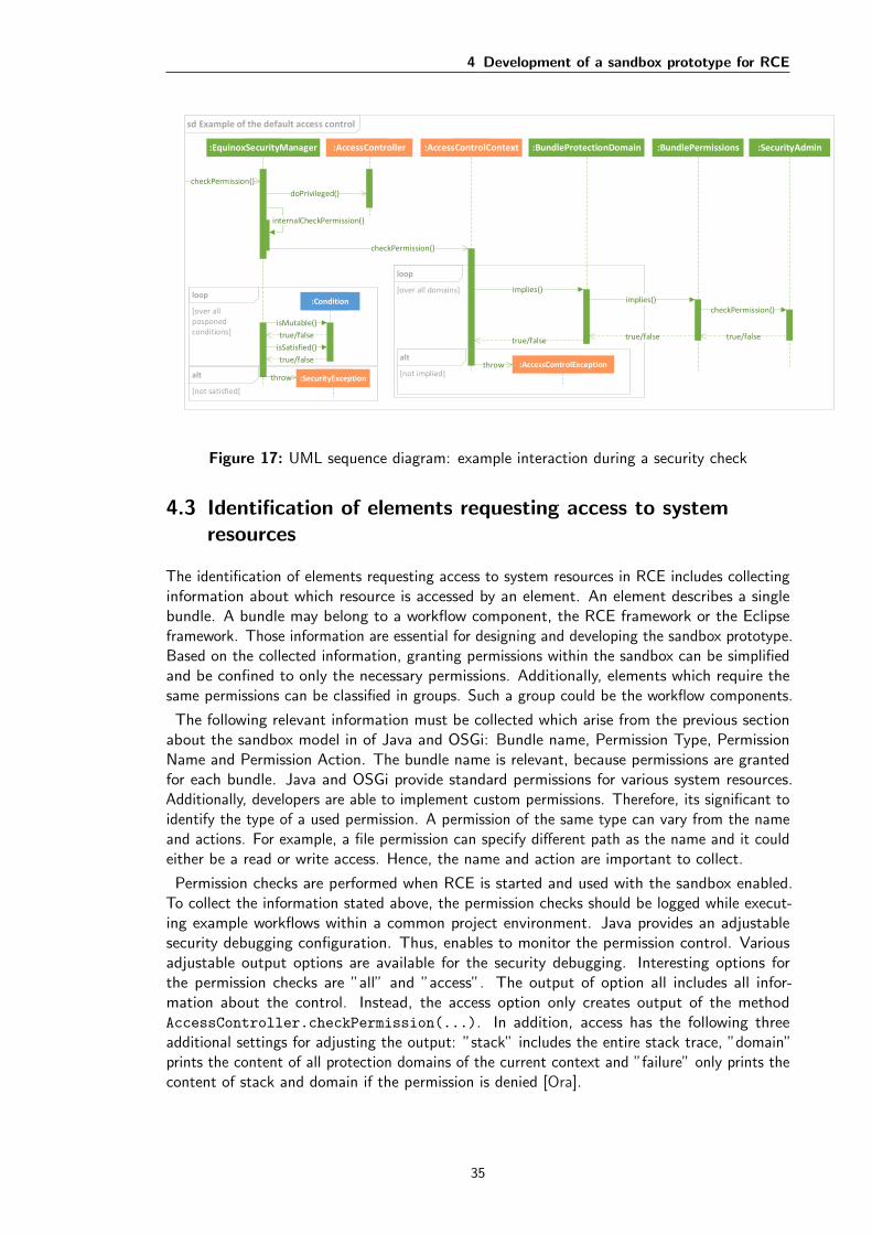
4 Development of a sandbox prototype for RCE
:EquinoxSecurityManager :AccessController
sd Example of the default access control
:AccessControlContext :BundleProtectionDomain :BundlePermissions :SecurityAdmin
checkPermission()
doPrivileged()
internalCheckPermission()
checkPermission()
loop
[over all domains] implies()implies()
checkPermission()
true/falsetrue/falsetrue/false
:AccessControlExceptionalt
[not implied]throw
:Conditionloop
[over all posponed conditions]
isMutable()
true/false
isSatisfied()
true/false
:SecurityExceptionthrowalt
[not satisfied]
Figure 17: UML sequence diagram: example interaction during a security check
4.3 Identification of elements requesting access to systemresources
The identification of elements requesting access to system resources in RCE includes collectinginformation about which resource is accessed by an element. An element describes a singlebundle. A bundle may belong to a workflow component, the RCE framework or the Eclipseframework. Those information are essential for designing and developing the sandbox prototype.Based on the collected information, granting permissions within the sandbox can be simplifiedand be confined to only the necessary permissions. Additionally, elements which require thesame permissions can be classified in groups. Such a group could be the workflow components.
The following relevant information must be collected which arise from the previous sectionabout the sandbox model in of Java and OSGi: Bundle name, Permission Type, PermissionName and Permission Action. The bundle name is relevant, because permissions are grantedfor each bundle. Java and OSGi provide standard permissions for various system resources.Additionally, developers are able to implement custom permissions. Therefore, its significant toidentify the type of a used permission. A permission of the same type can vary from the nameand actions. For example, a file permission can specify different path as the name and it couldeither be a read or write access. Hence, the name and action are important to collect.
Permission checks are performed when RCE is started and used with the sandbox enabled.To collect the information stated above, the permission checks should be logged while execut-ing example workflows within a common project environment. Java provides an adjustablesecurity debugging configuration. Thus, enables to monitor the permission control. Variousadjustable output options are available for the security debugging. Interesting options forthe permission checks are ”all” and ”access”. The output of option all includes all infor-mation about the control. Instead, the access option only creates output of the methodAccessController.checkPermission(...). In addition, access has the following threeadditional settings for adjusting the output: ”stack” includes the entire stack trace, ”domain”prints the content of all protection domains of the current context and ”failure” only prints thecontent of stack and domain if the permission is denied [Ora].
35
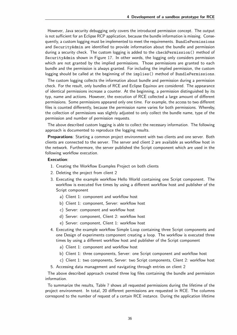
4 Development of a sandbox prototype for RCE
However, Java security debugging only covers the introduced permission concept. The outputis not sufficient for an Eclipse RCP application, because the bundle information is missing. Conse-quently, a custom logging must be implemented to meet the requirements. BundlePermissionsand SecurityAdmin are identified to provide information about the bundle and permissionduring a security check. The custom logging is added to the checkPermission() method ofSecurityAdmin shown in Figure 17. In other words, the logging only considers permissionwhich are not granted by the implied permissions. Those permissions are granted to eachbundle and the permission is always granted. For including the implied permission, the customlogging should be called at the beginning of the implies() method of BundlePermissions.
The custom logging collects the information about bundle and permission during a permissioncheck. For the result, only bundles of RCE and Eclipse Equinox are considered. The appearanceof identical permissions increase a counter. At the beginning, a permission distinguished by itstyp, name and actions. However, the execution of RCE collected a large amount of differentpermissions. Some permissions appeared only one time. For example, the access to two differentfiles is counted differently, because the permission name varies for both permissions. Whereby,the collection of permissions was slightly adjusted to only collect the bundle name, type of thepermission and number of permission requests.
The above described custom logging is able to collect the necessary information. The followingapproach is documented to reproduce the logging results.
Preparations: Starting a common project environment with two clients and one server. Bothclients are connected to the server. The server and client 2 are available as workflow host inthe network. Furthermore, the server published the Script component which are used in thefollowing workflow execution.
Execution:
1. Creating the Workflow Examples Project on both clients
2. Deleting the project from client 2
3. Executing the example workflow Hello World containing one Script component. Theworkflow is executed five times by using a different workflow host and publisher of theScript component
a) Client 1: component and workflow host
b) Client 1: component, Server: workflow host
c) Server: component and workflow host
d) Server: component, Client 2: workflow host
e) Server: component, Client 1: workflow host
4. Executing the example workflow Simple Loop containing three Script components andone Design of experiments component creating a loop. The workflow is executed threetimes by using a different workflow host and publisher of the Script component
a) Client 1: component and workflow host
b) Client 1: three components, Server: one Script component and workflow host
c) Client 1: two components, Server: two Script components, Client 2: workflow host
5. Accessing data management and navigating through entries on client 2
The above described approach created three log files containing the bundle and permissioninformation.
To summarize the results, Table 7 shows all requested permissions during the lifetime of theproject environment. In total, 20 different permissions are requested in RCE. The columnscorrespond to the number of request of a certain RCE instance. During the application lifetime
36

4 Development of a sandbox prototype for RCE
Permission Type Client1 Client2 ServerAdaptPermission 21,753 968 6,979
AdminPermission 14,295 15,909 8,290
AllPermission 2 2 2
ApplicationAdminPermission 1 1 1
BundlePermission 1,587 1,595 1,603
CapabilityPermission 613 617 621
ConfigurationPermission 440 440 599
FilePermission 231,037 81,884 136,606
LoggingPermission 21 21 21
ManagementPermission 7 7 7
MBeanPermission 6 6 6
MBeanServerPermission 4 4 4
MBeanTrustPermission 3 3 3
PackagePermission 10,542 10,614 10674
PropertyPermission 5,068 1,945 985
ReflectPermission 1,435 923 1,227
RuntimePermission 193,740 34,597 129,288
ServicePermission 281,955 205,404 209,777
SocketPermission 27 27 65
TopicPermission 26,216 2,353 9238
Total permission requests 788,752 357,320 515,996
Table 7: Requested permissions
and execution of workflows, a large amount of permissions are requested. Client 1 performedthe most request with over 700,000, because all workflows are started on this instance. TheFilePermission and ServicePermission are requested with noticeable high amounts on allthree instances. Additionally, the SocketPermission was requested more often on the serverinstance. The socket permission protects all access to create or listen to a network. The higheramount of socket requests is appropriate, because the server provides connection between otherinstances in the network. Therefore, Section A.3 shows differences between the instances forrequesting the socket permission.
4.4 Classification of the sandbox prototype of RCE
The sandbox prototype falls into one of the three sandbox categories described in Section 2.2.The classification is based on the properties of the sandbox implementation in Java and OSGi.Key properties of both sandbox models is illustrated in Figure 18. Java introduced a mechanismfor controlling the access to sensitive resources with the SecurityManager class. Sensitiveresources are represented by certain Permissions. For example, FilePermission representsthe access to the file system. OSGi build the sandbox model on top of the established APIof Java. Therefore, the permission concept is carried on to enforce a security policy for anapplication. Furthermore, the condition concept was introduced by OSGi. The purpose ofConditions are to guard a set of permissions. First, the conditions must be satisfied to begranted the guarded permissions and thus to gain access to the system resource.
37
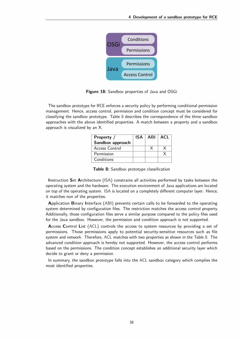
4 Development of a sandbox prototype for RCE
OSGiPermissions
Conditions
JavaAccess Control
Permissions
Figure 18: Sandbox properties of Java and OSGi
The sandbox prototype for RCE enforces a security policy by performing conditional permissionmanagement. Hence, access control, permission and condition concept must be considered forclassifying the sandbox prototype. Table 8 describes the correspondence of the three sandboxapproaches with the above identified properties. A match between a property and a sandboxapproach is visualized by an X.
Property /Sandbox approach
ISA ABI ACL
Access Control X X
Permission X
Conditions
Table 8: Sandbox prototype classification
Instruction Set Architecture (ISA) constrains all activities performed by tasks between theoperating system and the hardware. The execution environment of Java applications are locatedon top of the operating system. ISA is located on a completely different computer layer. Hence,it matches non of the properties.
Application Binary Interface (ABI) prevents certain calls to be forwarded to the operatingsystem determined by configuration files. The restriction matches the access control property.Additionally, those configuration files serve a similar purpose compared to the policy files usedfor the Java sandbox. However, the permission and condition approach is not supported.
Access Control List (ACL) controls the access to system resources by providing a set ofpermissions. Those permissions apply to potential security-sensitive resources such as filesystem and network. Therefore, ACL matches with two properties as shown in the Table 8. Theadvanced condition approach is hereby not supported. However, the access control performsbased on the permissions. The condition concept establishes an additional security layer whichdecide to grant or deny a permission.
In summary, the sandbox prototype falls into the ACL sandbox category which complies themost identified properties.
38

4 Development of a sandbox prototype for RCE
4.5 Design and implementation of the sandbox prototype forRCE
The user stories described in the product backlog 4 are required for the success of the prototypeimplementation. The spike stories (S1-S2) are previously described. The gained knowledge isused in the design and implementation. The section is divided into design and implementationactivities.
The design section develops a concept in virtue of the user stories. Firstly, the relationshipbetween functional user stories is illustrated by an use case diagram. The concept suggestsdialog prototypes for the interaction between the administrator and the RCE system. Permissiongroups are identified based on the logging results. Lastly, the extension options illustrated inthe class diagram 16 are considered for the implementation.
The execution of the concept is described in the implementation section. It includes theimplementation of the prototype dialogs. Moreover, the approach is explained how writeaccess to the data management is granted and which alternative exist. Finally, a class diagramillustrates all relevant classes of the implemented prototype.
4.5.1 Design
The developer instruction (I1) is described in Section A.2. All developers are advised to gainknowledge about the permission concept and to identify the maximum amount of permissionused by their bundle. Specifying the maximum set of permissions has several benefits. First ofall, a bundle can never receive more permissions than required. Developer must ensure that thebundle works properly with the determined permissions. Other developers can quickly reviewrequired permissions and identify potential security-risks. RCE is designed to offer extensionfeatures. Bundles created by third party developers can be easily reviewed in terms of localpermissions. Accordingly, local permissions are excellent for decision making whether the bundleshould be integrated into RCE.
The RCE launch configuration must be edit for the purpose of activating the securitymechanisms in RCE (R1). One of the VM arguments shown in Listing 5 must be added to thelaunch configuration. During application start, the following code ensures that RCE only startswith active sandbox:
1 if(System.getSecurityManager () == null) {
2 throw new IllegalStateException("Install a security manager to start
RCE.");
3 }
Listing 9: Start RCE only with active sandbox
At start up time, the management of permission should be initialized by providing defaultpermissions (R2). The logging results of bundles requesting permissiosn in RCE is used toidentify permission groups. The following three permission groups can be identified: framework,workflow components and standard. The permission granted vary from the permission group.
First group, the framework group receives AllPermissions based on specific bundle locations.Hence, the permission is guarded by the BundleLocationCondition. The purpose is to ensurethat Eclipse Equinox and the RCE framework bundles can perform all necessary operationswithout restrictions. Therefore, all bundles belonging to the Eclipse and RCE frameworkcompose the framework permission group. The bundles can be identified by the prefix of”de.rcenvironment.core”, ”de.rcenvironment.platform” and ”org.eclipse”. Each bundle must begranted with the permission separately, because the bundle can always satisfy only one location
39

4 Development of a sandbox prototype for RCE
condition. For performance reasons, the bundle responsible for the permission managementshould be added to the permission table as first entry. All changes to the permission tablerequires all permission and triggers a security check. The security check completes fasterwhen the first entry grants the permission to the manager bundle. The bundle and classes formanaging permissions is created in the process of the prototype.
The second permission group are all bundles composing workflow components. All workflowcomponent bundles have the same prefix ”de.rcenvironment.components”. The workflow com-ponent permission groups is granted with ServicePermission for publishing and requestingservices. There are currently 84 workflow component bundles available and 29 of those alreadyrequest services provide in RCE. Additionally, new bundles and extensions should have theopportunity to publish and request services. Granting the service permission complies with therequirements of the reusable approach of RCE. Each component bundle is granted the servicespermission protected by a BundleLocationCondition.
Standard is the last permission group. Its purpose is to grant standard permissions toall bundles. The following three permissions are requested by the majority of all bundles:PackagePermission, BundlePermission and CapabilityPermission. Those three per-missions should be granted without a condition. As a result, each bundle protection domain isgranted those permissions.
All functional user stories are illustrated in the use case diagram shown in Figure 19. Ad-ditionally, the relationship between the user and administrator role is visualized. A user hasautomatically the administrator role for the own local instance. During the execution ofworkflows, the user is not granted the administrator role on remote instances. A use case isdescribed as an ellipse within the boarder of the RCE system.
All grey use cases are already implemented in the RCE framework. They are included to showthe purpose of the user role and how the security check is triggered. The use case securitycheck has a grey orange color indicating that it is available, but it must be activated. The usecase is activated through installing a security manager in RCE (R1). The blue use cases aresubject to be implemented for the sandbox prototype.
A user can only execute a worfklow at a local or remote RCE instance. The execution triggersthe security check for accesses to sensitive resources. Four functionalities are available for theadministrator the whole time. However, one functionality can only be used when triggered bythe security check.
OSGi sandbox model is the foundation of the sandbox prototype. Three extension optionsare provided as illustrated in Figure 16. A manager implementation is necessary to managethe security policy. Permissions may be protected by a custom condition. Lastly, custompermissions can protect sensitive resources within the RCE framework. The extensions providedby the OSGi sandbox model are mapped to the user stories of the prototype.
Manager implementation
OSGi provides the Conditional Permission Admin Service (CPAS) to manage permissions at thebundle level. A manager class should be implemented for the prototype to offer functionalitiesto manage RCEs permissions. The manager class is required by the following user stories: R2,D1-D2 and C1-C4.
First of all, the default permissions must be initialized (R2). The above specified permissiongroups receive certain permissions which must be added to the policy table. Therefore, themanager class must provide an initial operation.
The administrator can interact with the manager class through a dialog provided by the use
40

4 Development of a sandbox prototype for RCE
User
Admin
execute workflow select execution instance
<<include>>
select local instance select remote instancesecurity check
extension points:undetermined permission
<<include>>
display bundles for configuring permissions
load bundle names of workflow components
<<include>>
grant permissions for a bundle
revoke permissions for a bundle
show admin prompt
<<extend>>
Condition: {Bundle is not granted the permission}Extension point: undetermined permission
respond admin prompt <<include>>
load granted permissions for a workflow component
<<include>>
respond with temporary decision
respond with permanent decision
edit permissions for a bundle
Figure 19: Concept UML Use Case diagram
case display bundles for configuring permissions (C1). The use case includes the two use casesof the data acquisition category. Both are used to load relevant information to be displayed inthe dialog. First, the dialog is provided with a list of all bundle names by the use case loadbundle names of workflow components (D1). The administrator can select a bundle name toload and display the granted permissions of the bundle (D2). Additionally, the dialog providesthe administrator to add, edit and remove permissions for a selected bundle (C2-C4).
A prototype for the permission control dialog is illustrated in Figure 20. However, it showstwo different dialogs. The dialog in the background is the main dialog to display the bundlesand granted permissions (C1). For adding or editing permissions, a second dialog is prompted(C2-C3). The administrator enters the permission type, name and actions. After adding orediting a permission, the dialog calls an operation of the manager class which executes thechange in the policy table. To edit or remove a granted permission, the permission must beselected to enable the corresponding action buttons.
The traceability matrix 5 shows a precondition for all configuration user stories to the OSGiService spike story (S3). The permission control dialog requires access to the manager class.Furthermore, RCE can be executed without GUI and the manager should be accessible througha command console. Hence, the manager implementation should be designed as a service andpublished in RCE.
The sandbox prototype works without the implementation of the user stories (P1-P2). However,
41

4 Development of a sandbox prototype for RCE
Permission Control Dialog
OK
Add...
Edit...
Remove
Type Name Action
Component
Script
InputProvider
OutputProvider
Switch
Optimizer
...
Granted Permission
FilePermission readC:\temp
SocketPermiss connect,resol102.95.13.7
Add Permission
CancelOK
Name All
FilePermission <Permission
Action read
write
delete
P
P
P
Figure 20: Permission control dialog prototype
all permissions granted by the administrator are gone after a restart of the RCE instance. Allchanges made by the administrator to the policy table should be persistently stored (P1). Atthe start up of RCE, the stored permissions should be loaded (P2). Additionally, those needto be added back to the policy table. The granted permissions should be added during theinitialization of the permission groups (R2).
<<interface>>
ConditionalPermissionManager
+ initialize()+ components() : List<String>+ grantedPermissionsFor(bundleName :String) : List<String>+ addPermission()+ editPermission()+ removePermission()+ savePermissions()+ loadPermissions() : List<String>
Figure 21: UML Class diagram: Manager implementation
Figure 21 shows a class diagram of the manager class providing functionalities based on theuser stories described above. The class is actually an interface, due to the requirements for anOSGi service. The service must be published and the dialog implementation can request theservice and use the provided operations.
42

4 Development of a sandbox prototype for RCE
Custom condition
Consider the following scenario, a workflow component is not granted a specific permissionduring the workflow execution. The prototype should prefer to ask the administrator to grantthe permission rather than to terminate the workflow. RCE needs to provide a dialog forundetermined permissions (W1). A custom condition is a great way to interact with theadministrator as identified by the spike story (S2). A new UserPromptCondition is to beimplemented to prompt a dialog and whether or not to grant the permission. For the interaction,the user prompt condition must be a postponed condition. The proposed implementationrequires the RCE instance to run with the GUI. Future improvements should considered apossible interaction with the administrator when the RCE instance is started without a GUI.
The administrator is able to make temporary or permanent decisions about granting or denyingthe permission (W2-W3). Hence, the condition is by default mutable. The condition maychange to immutable when the administrator makes a permanent decision. In this case, theresult should be cached and the dialog should not be prompted again for the bundle requestingthe permission. The permission should be added to the policy table when allowed permanently(W3). For the temporary decision, the permission is only allowed for one access to the resource(W2). Therefore, the dialog may be prompted multiple times for the same resource.
Permission request
DenyAllow
Do you want to grant %permission_name to %workflow_component_name?
Allow temporary Deny temporary
Figure 22: User prompt dialog (W1)
Figure 22 shows a prototype of the user prompt dialog. The buttons ”Allow” and ”Deny” areused for permanent decisions about the permission. The placeholder in the question should bereplaced by the actual bundle name and permission type.
During a workflow execution, workflow components require permissions to system resourcessuch as the file system or network. Those permissions must be added with the user promptcondition to the policy table during the initialization of the default permissions (R2). Forexample, undetermined access to files or network resources should prompt the dialog.
Custom permission
Custom permissions can be used to protect resources of RCE. For example, the data managementis such a sensitive resource. The results of workflows can be accessed by every user of a projectenvironment. In other words, every user can read and delete data on remote instances. In thiscase, a custom data management permission could protect the access to the generated data.Every user may be granted read access. However, only the instance owner is granted the deletepermission. Thus, prevents users from deleting relevant research data on a remote instance.Each operation accessing sensitive resources must be extended to call the security manager tocheck whether the operation is granted or not. Listing 4 provides an example how to access
43
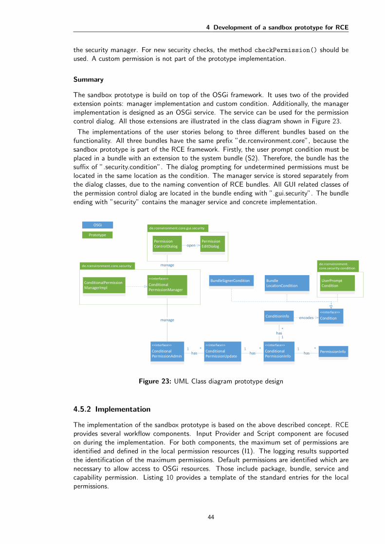
4 Development of a sandbox prototype for RCE
the security manager. For new security checks, the method checkPermission() should beused. A custom permission is not part of the prototype implementation.
Summary
The sandbox prototype is build on top of the OSGi framework. It uses two of the providedextension points: manager implementation and custom condition. Additionally, the managerimplementation is designed as an OSGi service. The service can be used for the permissioncontrol dialog. All those extensions are illustrated in the class diagram shown in Figure 23.
The implementations of the user stories belong to three different bundles based on thefunctionality. All three bundles have the same prefix ”de.rcenvironment.core”, because thesandbox prototype is part of the RCE framework. Firstly, the user prompt condition must beplaced in a bundle with an extension to the system bundle (S2). Therefore, the bundle has thesuffix of ”.security.condition”. The dialog prompting for undetermined permissions must belocated in the same location as the condition. The manager service is stored separately fromthe dialog classes, due to the naming convention of RCE bundles. All GUI related classes ofthe permission control dialog are located in the bundle ending with ”.gui.security”. The bundleending with ”security” contains the manager service and concrete implementation.
<<interface>>
ConditionalPermissionAdmin
1 *has
<<interface>>
ConditionalPermissionInfo
*1has PermissionInfo
<<interface>>
Condition
BundleSignerCondition BundleLocationCondition
manage
1 *has
1
*has
encodes
<<interface>>
ConditionalPermissionUpdate
ConditionInfo
OSGi
Prototype
<<interface>>
ConditionalPermissionManager
UserPromptCondition
ConditionalPermissionManagerImpl
PermissionControlDialog
manage
PermissionEditDialogopen
Figure 23: UML Class diagram prototype design
4.5.2 Implementation
The implementation of the sandbox prototype is based on the above described concept. RCEprovides several workflow components. Input Provider and Script component are focusedon during the implementation. For both components, the maximum set of permissions areidentified and defined in the local permission resources (I1). The logging results supportedthe identification of the maximum permissions. Default permissions are identified which arenecessary to allow access to OSGi resources. Those include package, bundle, service andcapability permission. Listing 10 provides a template of the standard entries for the localpermissions.
44

4 Development of a sandbox prototype for RCE
1 # Allow importing and exporting of all packages
2 (org.osgi.framework.PackagePermission "*" "import ,exportonly")
3 # Allow all bundle actions
4 (org.osgi.framework.BundlePermission "*" "provide ,require ,host ,fragment")
5 # Allow requesting and publishing services
6 (org.osgi.framework.ServicePermission "*" "get ,register")
7 # Allow capabilities
8 (org.osgi.framework.CapabilityPermission "*" "provide ,require")
Listing 10: Local default permissions for the OSGi framework
Additionally to the standard permissions, specific permissions of a workflow component mustadded to the resource. Input Provider has the functionality to provide a file or directory as anoutput type. Hence, it requires read access to files and directories. All component write theprocessed data into the data management. Thus, the input provider component needs to begranted write access as well.
The Script component provides the execution of scripts. Thus, it may require a diverse set ofpermissions such as full access to the file system and connection to the network. Moreover, thelogging results shows which permissions are requested by the script bundles. The script bundlesrequested the additional permissions: admin, property, reflect, topic, adapt and runtime. Thosemust be added to the local permissions set. Script component has three bundles responsiblefor the execution functionalities. Hence, each bundle must contain their own local permissionresource.
The RCE launch configuration contains the VM argument to install the security managerof OSGi (R1). RCE framework is started through a Application class. The class is used toverify whether a security manager is installed by using the example of Listing 9. Additionally,the application class requests the manager service to initialize the policy table (R2).
Manager implementation
The manager implementation is realized as an OSGi service (S3). It uses the CPAS to managethe policy table of RCE. Therefore, it provides the methods shown in Figure 21. The methodinitialize() is responsible to add the permissions for the default groups to the policy table(R2). For the third permission group called standard, three permissions were intended on thedesign. However, during the execution of RCE with active sandbox further permissions arerequired. It includes the following three permissions which are added to the standard group:property, log and runtime permission. All those permissions are added without a condition tothe policy table.
The Permission control dialog uses the manager service to display all workflow componentbundles and their granted permissions (C1). The user stories of the data acquisition category areimplemented through the components() (D1) and grantedPermissionsFor(bundleName)
(D2) methods provided by the manager service. The design of the permission control dialogis based on the prototype shown in Figure 20. The administrator is able to add, edit andremove permissions for each bundle (C2-C4). All workflow components are granted the servicepermission by default. It appears in the permission control dialog. However, the administratorcan not edit or remove a default permission.
Figure 24 shows the permission dialog implemented in RCE. The user story IDs necessary for thedialog are represented within the figure. For example, the control buttons to manage permissions(C2-C4) are located on the right side of the permission dialog (C1). The administrator hasaccess to the permission dialog at any time. CPAS guarantees that all changes to the policytable are in real time. RCE provides access to the dialog via the tool bar and the file menu.
45
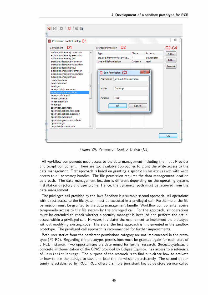
4 Development of a sandbox prototype for RCE
C3
C2-C4
C1
D1 D2
Figure 24: Permission Control Dialog (C1)
All workflow components need access to the data management including the Input Providerand Script component. There are two available approaches to grant the write access to thedata management. First approach is based on granting a specific FilePermission with writeaccess to all necessary bundles. The file permission requires the data management locationas a path. The data management location is different depending on the operating system,installation directory and user profile. Hence, the dynamical path must be retrieved from thedata management.
The privileged call provided by the Java Sandbox is a suitable second approach. All operationswith direct access to the file system must be executed in a privileged call. Furthermore, the filepermission must be granted to the data management bundle. Workflow components receivetemporarily access to the file system by the privileged call. For the approach, all operationsmust be extended to check whether a security manager is installed and perform the actualaccess within a privileged call. However, it violates the requirement to implement the prototypewithout modifying existing code. Therefore, the first approach is implemented in the sandboxprototype. The privileged call approach is recommended for further improvements.
Both user stories from the persistent permissions category are not implemented in the proto-type (P1-P2). Regarding the prototype, permissions must be granted again for each start ofa RCE instance. Two opportunities are determined for further research. SecurityAdmin, aconcrete implementation of the CPAS provided by Eclipse Equinox, has access to a referenceof PermissionStorage. The purpose of the research is to find out either how to activateor how to use the storage to save and load the permissions persistently. The second oppor-tunity is established by RCE. RCE offers a simple persistent key-value-store service called
46

4 Development of a sandbox prototype for RCE
PersistentSettingsServices. During the shutdown process of RCE, the services may beused to save all permissions added by the administrator (P1). The initialization of the policytable should restore the permissions and add them together with the default permissions to thepolicy table (R2).
Custom Condition
The purpose of the UserPromptCondition is to provide a good user experience. A workflowasks the administrator for granting a missing permission before terminating the workflow(W1). The effective permissions of a bundle are the intersection between the local andsystem permissions. Hence, the system permissions must grant the same specific permissionsas determined in the local permission resource. Either those are explicitly granted by theadministrator or the system prompts a dialog to allow or deny the permission.
In the last case, the specific permissions are added to the policy table protected by theUserPromptCondition. For example, specific permissions are file, socket or even runtimepermissions. Each permission is added with a single action and a wild card as name to matchall possible resources. Listing 11 contains encoded examples of the specific permissions guardedby UserPromptCondition.
1 ALLOW {
2 [UserPromptCondition "FilePermission" "<<ALL FILES >>" "read"]
3 (FilePermission "<<ALL FILES >>" "read")
4 } "1"
5 ALLOW {
6 [UserPromptCondition "FilePermission" "<<ALL FILES >>" "write"]
7 (FilePermission "<<ALL FILES >>" "write")
8 } "2"
9 ALLOW {
10 [UserPromptCondition "SocketPermission" "*" "accept"]
11 (SocketPermission "*" "accept")
12 } "3"
Listing 11: Specific permissions protected by the UserPromptCondition
The dialog requires a certain set of information to provide a message for the administratorwhich bundle requests a permission. The message requires the bundle name, permission type,name and action. However, a condition is unaware of the permission it protects. It only knowsthe bundle requesting the protected permission. Therefore, a user prompt condition containsthe permission information as arguments as shown in the Listing 11. Based on the arguments,the dialog can display a message containing bundle name, permission type and action. Theactual name of the resource cannot be displayed, because it is not provided to the condition.In order to provide a clear message to the administrator, a permission is added only with oneaction. Therefore, permissions providing several actions are added separately like shown withthe file permission. Otherwise, a message could contain the file action read and write during aread access.
Figure 25 shows the user condition dialog during a workflow execution (W1). The messagecontains information about the Script component requesting a read access to a file. However,the message is not clear about which specific component of the workflow requests the permission.For example, a workflow contains several Script components. During a permission request, it isnot possible to clearly assign a request to one specific Script component. Additionally, the usercondition dialog is also prompted outside a workflow execution. For instance, the GUI bundleof a component requires file access.
The condition dialog is implemented in Swing, due to the limitation of the extension tothe system bundle. The dialog itself must be created and displayed within a privileged call.
47
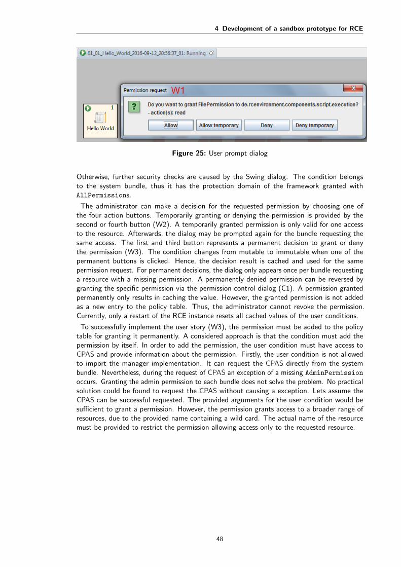
4 Development of a sandbox prototype for RCE
W1
Figure 25: User prompt dialog
Otherwise, further security checks are caused by the Swing dialog. The condition belongsto the system bundle, thus it has the protection domain of the framework granted withAllPermissions.
The administrator can make a decision for the requested permission by choosing one ofthe four action buttons. Temporarily granting or denying the permission is provided by thesecond or fourth button (W2). A temporarily granted permission is only valid for one accessto the resource. Afterwards, the dialog may be prompted again for the bundle requesting thesame access. The first and third button represents a permanent decision to grant or denythe permission (W3). The condition changes from mutable to immutable when one of thepermanent buttons is clicked. Hence, the decision result is cached and used for the samepermission request. For permanent decisions, the dialog only appears once per bundle requestinga resource with a missing permission. A permanently denied permission can be reversed bygranting the specific permission via the permission control dialog (C1). A permission grantedpermanently only results in caching the value. However, the granted permission is not addedas a new entry to the policy table. Thus, the administrator cannot revoke the permission.Currently, only a restart of the RCE instance resets all cached values of the user conditions.
To successfully implement the user story (W3), the permission must be added to the policytable for granting it permanently. A considered approach is that the condition must add thepermission by itself. In order to add the permission, the user condition must have access toCPAS and provide information about the permission. Firstly, the user condition is not allowedto import the manager implementation. It can request the CPAS directly from the systembundle. Nevertheless, during the request of CPAS an exception of a missing AdminPermission
occurs. Granting the admin permission to each bundle does not solve the problem. No practicalsolution could be found to request the CPAS without causing a exception. Lets assume theCPAS can be successful requested. The provided arguments for the user condition would besufficient to grant a permission. However, the permission grants access to a broader range ofresources, due to the provided name containing a wild card. The actual name of the resourcemust be provided to restrict the permission allowing access only to the requested resource.
48
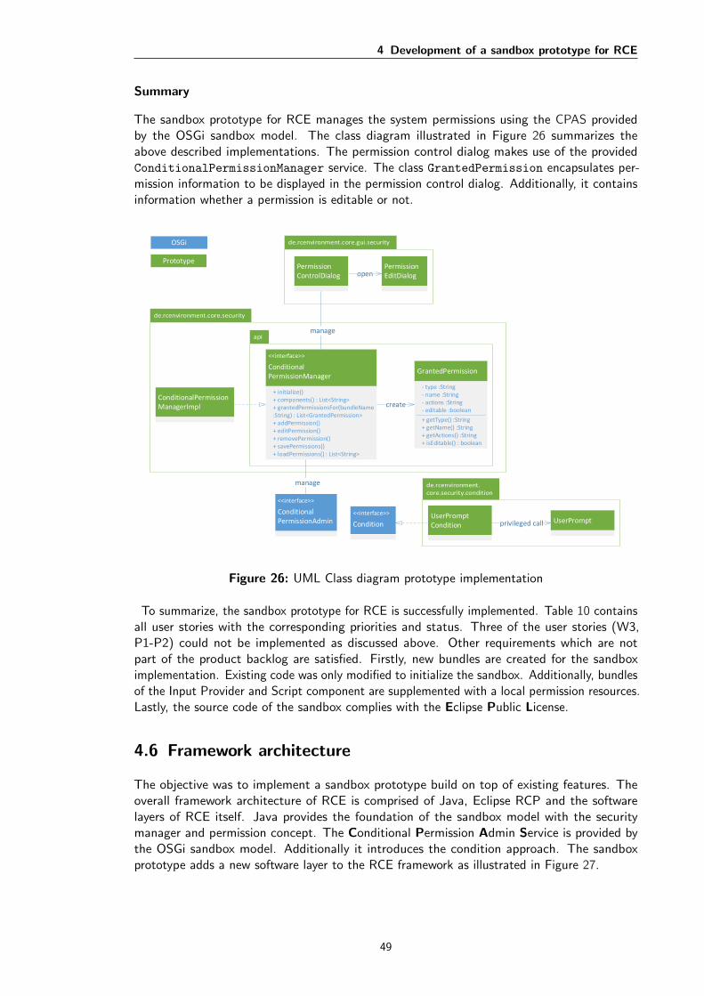
4 Development of a sandbox prototype for RCE
Summary
The sandbox prototype for RCE manages the system permissions using the CPAS providedby the OSGi sandbox model. The class diagram illustrated in Figure 26 summarizes theabove described implementations. The permission control dialog makes use of the providedConditionalPermissionManager service. The class GrantedPermission encapsulates per-mission information to be displayed in the permission control dialog. Additionally, it containsinformation whether a permission is editable or not.
<<interface>>
ConditionalPermissionAdmin
<<interface>>
Condition
manage
OSGi
Prototype
UserPromptCondition
ConditionalPermissionManagerImpl
PermissionControlDialog
PermissionEditDialogopen
UserPromptprivileged call
GrantedPermission
<<interface>>
ConditionalPermissionManager
+ initialize()+ components() : List<String>+ grantedPermissionsFor(bundleName :String) : List<GrantedPermission>+ addPermission()+ editPermission()+ removePermission()+ savePermissions()+ loadPermissions() : List<String>
- type :String- name :String- actions :String- editable :boolean
+ getType() :String+ getName() :String+ getActions() :String+ isEditable() : boolean
manage
create
Figure 26: UML Class diagram prototype implementation
To summarize, the sandbox prototype for RCE is successfully implemented. Table 10 containsall user stories with the corresponding priorities and status. Three of the user stories (W3,P1-P2) could not be implemented as discussed above. Other requirements which are notpart of the product backlog are satisfied. Firstly, new bundles are created for the sandboximplementation. Existing code was only modified to initialize the sandbox. Additionally, bundlesof the Input Provider and Script component are supplemented with a local permission resources.Lastly, the source code of the sandbox complies with the Eclipse Public License.
4.6 Framework architecture
The objective was to implement a sandbox prototype build on top of existing features. Theoverall framework architecture of RCE is comprised of Java, Eclipse RCP and the softwarelayers of RCE itself. Java provides the foundation of the sandbox model with the securitymanager and permission concept. The Conditional Permission Admin Service is provided bythe OSGi sandbox model. Additionally it introduces the condition approach. The sandboxprototype adds a new software layer to the RCE framework as illustrated in Figure 27.
49

4 Development of a sandbox prototype for RCE
The new security layer provides the sandbox of RCE. For the permission management of RCE,the security manager and CPAS of OSGi is used. Furthermore, the sandbox provides am OSGiservice called ConditionalPermissionManager to manage the system wide permissions. Alllayers above and the GUI can request the service to manage the permissions. The adminis-trator can use the established PermissionControlDialog to administer the permissions foreach worklfow component. To interact with the administrator for missing permissions, theUserPromptCondition is introduced which displays a user prompt dialog.
Security
RCE FrameworkG
UI
Security
Eclipse RCP/OSGi
ConditionalPermissionManager
ConditionalPermissionAdmin
Distribution
Notification
Privilege Management
Data Management Workflow Engine
Components
PermissionControlDialog
UserPromptUserPrompt
Condition
Figure 27: RCE Framework with the new security layer [SFL+12]
50

5 Evaluation of the sandbox prototype
This chapter evaluates the impact of the implemented sandbox prototype on security and userexperience. For this purpose, three test workflows are designed using the Input Provider andScript component. The prototype implementation only focused on these two components, dueto the complexity of the RCE framework and large number of provided standard components.Hence, local permission resources are exclusively created for the Input Provider and Scriptcomponent.
Test cases are described to ensure correct operation behavior of the prototype. Each test casecontains the execution steps that must be performed to achieve the expected result. Expectedresults are the execution outcome of workflows or permission requests for missing permissions.Those test cases are grouped into test suites to evaluate similar aspects like the appearanceof permission request dialogs, execution of local and remote workflows. Test suites contain ashort description and preconditions for the performance of the test cases. The actual resultsare compared and evaluated with the expected result for each test case.
The test suites and the results provided in Appendix A.5 (page 63) show the impact onsecurity and user experience. However, the sandbox prototype has limitations in the executionof workflows. Not all test cases are executed successfully. Especially, workflows executed ona remote instance and workflows with connected components terminate in an error due toinsufficient permissions.
5.1 Security
The effect of the prototype on security is tested by the first two test suites. Hence, workflowsare executed locally and remotely with and without granted permissions.
The Input Provider component is configured with a file output during the test cases. Therefore,it requires access to a particular file. The permission request dialog is always promptedsuccessfully if the file permission is not granted to the component. The dialog is only shownonce for a permanent decision. However, the permission granted by the permission requestdialog is too comprehensive. It provides access to all files. Thereby, granting the permissionpermanently for one file also allows the component to access any other file resource on thesystem. In terms of security, the permission should only allow the access to the requested file.To match all file resource requests the user prompt condition must protect the permission of allfile accesses. In conclusion, the permission should only be used to match and set off the dialog.Another permission should ony be granted with a specific file resource. The workflow is onlyexecuted successfully if the permission is granted. Thereby, the prototype restricts effectivelythe Input Provider component to access the file without the permission.
The Script component contains a script which prints a string on the RCE console. Thisoperation does not indicate a security-relevant access to resources. However, the script executionrequests access to seven different resources. The script is executed with Jython and Python,while Jython is only executed successfully. Nevertheless, the permission are still requested byPython, but it fails due to an unidentified permission. Hence, the sandbox constrains Pythonto execute scripts even with identified permissions granted.
The sandbox is very restrictive during the execution of connected components and on a remoteinstance. A workflow connects the Input Provider together with a Script component. TheInput Provider loads and sends a file to the Script. Previously the Input Provider had onlyrequested access to read the file, but it requires write access to forward the file to anothercomponent. The workflow fails due to missing permissions of the Script component, althoughthe component requested seven permissions for the execution. During the execution of workflows
51

5 Evaluation of the sandbox prototype
on a remote instance a similar behavior is observed. The workflows fails in all test cases dueto an unidentified permission. Hence, the prototype requires adjustment to grant necessarypermissions for previous cases.
In summary, it can be stated that the execution of workflows is limited if the necessarypermissions for the individual workflow components are unavailable. Therefore, the security ofRCE can be improved by the sandbox prototype. However, normal features such as connectedcomponents and remote workflow executions are negatively affected by the sandbox. Missingpermissions are requested whether they should be granted or not. Granting those permissionspermanently allows access to a wide range of resources, thus reducing the security of thepermission management.
5.2 User experience
The term user experience has been explained in section 4.1.1. The sandbox prototype introducesthe administrator role. Hence, the experience of the user and administrator interacting withRCE needs to be described. The interaction with RCE can be influenced by the sandbox in thefollowing manner: interruptions by permission request dialogs, delay of workflow execution ortermination due to an error.
The user interaction with RCE is the design and execution of workflows. Therefore, thesandbox can affect the experience negatively by delaying or failing the workflow execution.Responsible for managing permissions is the administrator. Hence, the administrator has to dealwith the interruption of permission request dialogs. He makes either a temporary or permanentdecision for the requested permissions. The effect of the decision for the user experience isevaluated by the third test suite.
A workflow component requests access to a system resource and could display a dialog fora missing permission. While the dialog is shown, the workflow execution is delayed. Thispermission can be granted or denied by the administrator. Thereby, the decision can be madetemporary or permanent. On the one hand, a permanent decision displays the dialog only once.Hence, RCE remembers the decision and either grants or denies the specific resource withoutshowing the dialog again. For the Input Provider component in the test cases only one dialog isshown to access the file. After granting it permanently RCE remembers to grant the permissionfor the same component. On the other hand, a temporary choice is only valid for one access toa resource. The dialog keeps reappearing until the access to the resource is completed. In thiscase the experience of the administrator with RCE is impacted negatively. As shown in the testsuites the dialogs appear several times when granting it temporarily. For the Input Providerthe dialog is displayed three more than when granting permanently. The Script componentproduces even over 100 permission request dialogs.
In conclusion, the security improvements enforced by the sandbox effects the user experiencemostly negatively. The permission request dialogs delay the workflow execution. Additionally,denied permission results in a failed workflow. The advantage of permanent decision for theuser experience is that RCE remembers which permission is allowed or denied. After a while ofusing RCE less dialogs are prompted. However, granting permissions temporarily requires theconfirmation repeatedly.
52

6 Conclusion and Future Work
The RCE framework is based on RCP which implements the Java framework OSGi. RCEprovides workflow components to create a simulation of a complex system. The componentsare executed in a so-called workflow either local, remote or combined. RCE grants full accessto system resources. Consequently, RCE is vulnerable to malicious code contained in a remotecomponent. The system security should be increased by providing an access control. Thegeneral purpose of access control is to control and restrict access to system resources. Thefollowing three isolation techniques have been analyzed to secure potentially RCE against theexecution of malicious code: Hypervisor-based, Container-based and Sandbox-based isolation.
The analyzed techniques provided different approaches to protect a system from damageduring the execution of remote code. The hypervisor-based and container-based techniqueestablishes a virtual environment of different scope for the execution of code. The isolationinherent in the virtual environment protects the system for damage. Only the sandbox-basedtechnique provides an access control based on a security policy. Additionally, Java has a build-insandbox model. Hence, a sandbox prototype has been implemented to examine whether it isan effective technique to secure RCE.
The objective of the thesis was to design and implement a sandbox prototype for RCE.OSGi provides an extension to the Java sandbox model to manage permissions based onconditions in real-time. OSGi established a service for the permission management. In addition,extension features are offered to create custom permissions and conditions. The sandboxprototype uses the provided service of OSGi to manage the permissions in RCE. Additionally,the prototype adds a dialog to configure the permissions by the administrator. A customcondition is implemented to display a dialog for missing permissions, thus an administrator cangrant or deny the permissions.
The identification of elements accessing system resources showed a high amount of permissionrequests. Therefore, a security policy can effectively be implemented with the sandbox toensure granted access to resources. It helps to secure the RCE framework.
The final evaluation shows that the sandbox prototype prevents the execution of workflowswithout the required permissions. Thereby, RCE offers more security against the execution ofmalicious code. However, the prototype restricts the execution of workflows on a remote instanceor with connected components. Apparently the execution on the network and for connectedcomponents requires additional permissions which have not been identified. The sandboxprototype requires precise adjustments for providing the appropriate amount of permissions toexecute RCE. The user experience is affected by the approval or disapproval dialog of missingpermissions.
In conclusion, the implemented sandbox prototype for RCE proves that sandbox is an effectivetechnique to secure the RCE framework. Finally, an outlook for further developments of thesandbox will be discussed in the following section introduced.
53
6 Conclusion and Future Work
Future Work
The sandbox prototype focuses on protecting the system resources. Thereby, access to sensitiveresources established by RCE are unprotected. Custom permissions can encapsulate the accessto those resources of RCE. For instance, data management access could be represented bya DataManagementPermission. Access control should be performed to decide whether anoperation for the resource is granted or not. Hence, confidential data stored on a remote RCEinstance can be access protected without permission.
The execution of workflows with missing permissions can result in delay or even leads toan early termination. RCE instances in a network can be configured to grant different setsof permissions to workflow components. To avoid delays or termination of workflows a RCEinstance should provide status information about the sandbox in the network. An instanceshould indicate whether it has started with the sandbox. Additionally, it should show whichpermissions are granted for certain workflow components. Then, instances can be selectedbased on the appropriate permissions provided for the execution. Otherwise, the workflow canbe adapted to the limitations of the execution environment.
The security layer of RCE can be supplemented by user authentication and authorization.Therefore, OSGi provides the role-based User Admin Service. Bundles can request the serviceto verify whether a user is authorized [HPMS11]. The service can be used to introduce the userand administrator role to RCE. Only the administrator role receives access to the permissioncontrol dialog. Furthermore, the visibility of entries in the data management or workflowcomponents can vary based on a role.
54

Bibliography
[And72] James P. Anderson. Computer Security Technology Planning Study. Technicalreport, U.S. Air Force Electronic Systems Division, 1972.
[AS11] Faisal Al Ameiri and Khaled Salah. Evaluation of popular application sandboxing.In International Conference for Internet Technology and Secured Transactions(ICITST), pages 358–362. IEEE, 2011.
[Bab] Charles Babcock. Containers Explained: 9 Essentials You Need To Know.Available: http://www.informationweek.com/strategic-cio/it-strategy/containers-explained-9-essentials-you-need-to-know/a/d-id/1318961 , Retrieved: August 2,2016.
[BRJI08] Adam Barth, Charles Reis, Collin Jackson, and Google Chrome Team Google Inc.The security architecture of the Chromium browser, 2008.
[Bui15] Thanh Bui. Analysis of Docker Security. arXiv preprint arXiv:1501.02967, pages1–7, 2015.
[Ebe11] Ralf Ebert. Eclipse RCP - Entwicklung von Desktop-Anwendungen mit der EclipseRich Client Platform 3.7, 2011.
[GMPS97] Li Gong, Marianne Mueller, Hemma Prafullchandra, and Roland Schemers. Goingbeyond the sandbox: An overview of the new security architecture in the javatmdevelopment kit 1.2. In USENIX Symposium on Internet Technologies and Systems,pages 103–112, 1997.
[HPMS11] Richard Hall, Karl Pauls, Stuart McCulloch, and David Savage. Osgi in Action:Creating Modular Applications in Java. Manning Publications Co., Greenwich, CT,USA, 1st edition, 2011.
[HS06] Almut Herzog and Nahid Shahmehri. A Usability Study of Security Policy Manage-ment, pages 296–306. Springer US, 2006.
[ISO98] Ergonomics of human-system interaction - Guidance on usability. Standard, Inter-national Organization for Standardization, Berlin, DE, 1998.
[ISO06] Ergonomics of human-system interaction - Dialogue principles. Standard, Interna-tional Organization for Standardization, Berlin, DE, 2006.
[ISO10] Ergonomics of human-system interaction - Human-centred design for interactivesystems. Standard, International Organization for Standardization, Berlin, DE,2010.
[MKK15] Robert Morabito, Jimmy Kjallman, and Miika Komu. Hypervisors vs. LightweightVirtualization: A Performance Comparison. In IEEE International Conference onCloud Engineering (IC2E), pages 386–393. IEEE, 2015.
[MSCS16] Michael Maass, Adam Sales, Benjamin Chung, and Joshua Sunshine. A systematicanalysis of the science of sandboxing. PeerJ Computer Science, 2:e43, 2016.
[Oak01] Scott Oaks. Java Security. O’Reilly Media, 2nd edition, 2001.
[Oli] Patrick Oliphant. Virtual Machines. Available:http://www.virtualcomputing.net/virtual-machines , Retrieved: July 31,2016.
[Ora] Oracle. Troubleshooting Security. Available:https://docs.oracle.com/javase/8/docs/technotes/guides/security/troubleshooting-security.html , Retrieved: August 27, 2016.
[OSG03] OSGi Alliance. OSGi Service Platform, Release 3, 2003.
[OSG11] OSGi Alliance. OSGi Service Platform Core Specification, Release 4, Version 4.3,
55

Bibliography
2011.
[Pro] Android Open Source Project. Android Security Overview. Available:https://source.android.com/security/index.html , Retrieved: July 28, 2016.
[Rub] Paul Rubens. Was sind Container und was macht man damit?: Con-tainer vs. Virtualisierung. Available: http://www.tecchannel.de/a/container-vs-virtualisierung,3201845 , Retrieved: August 1, 2016.
[SBM+13] Doreen Seider, Achim Basermann, Robert Mischke, Martin Siggel, Anke Troltzsch,and Sascha Zur. Ad hoc Collaborative Design with Focus on Iterative Multidisci-plinary Process Chain Development applied to Thermal Management of Spacecraft.In CEAS Aerospace Aerodynamics Research Conference (ISSN: 0001-9240), pages1–9. Link oping University Electronic Press, 2013.
[SFL+12] Doreen Seider, Philipp Fischer, Markus Litz, Andreas Schreiber, and Andreas Gerndt.Open Source Software Framework for Applications in Aeronautics and Space. InAerospace Conference, 2012 IEEE, pages 1–11. IEEE, 2012.
[SN05] James E. Smith and Ravi Nair. The Architecture of Virtual Machines. Computer,38(5):32–38, 2005.
[Ven00] Bill Venners. Inside the Java Virtual Machine. McGraw-Hill, Inc., New York, NY,USA, 2nd edition, 2000.
[VN10] Arun Viswanathan and B. C. Neuman. Survey of Isolation Techniques. unpublisheddraft, 2010.
[WHKL08] Gerd Wutherich, Nils Hartmann, Bernd Kolb, and Matthias Lubken. Die OSGiService Platform - Eine Einfuhrung mit Eclipse Equinox. dpunkt, Heidelberg,Germany, 1 edition, 2008.
[WT98] Alma Whitten and JD Tygar. Usability of security: A case study. Technical report,DTIC Document, 1998.
56

A Appendix
A.1 Sandbox classes summary
The class diagram 28 shows all Java classes which are helpful to understand the Java sandboxmodel.
SecurityManager1 1
has
AccessControlContext{final}
AccessController{final}
Permission{abstract}
check()*
ProtectionDomain
1
*
has
check()*
1
1
has
1
1
has
<<interface>>
Principal
1*has
CodeSource
System{final}
ClassLoader{abstract}
Policy{abstract}
implies()*
PermissionCollection{abstract}
1
1has
implies()**
* requires Permission** requires ProtectionDomain and Permission
AccessControlExceptionthrows
create
Figure 28: UML class diagram of the Java 2 Sandbox model
57

A Appendix
Table 9 contains all Java classes and interfaces of the Java sandbox model. It provides thepackage, name, usage and the JDK introduction version.
Package Interface/Class Name Usage JDK
java.lang
ClassLoader Loads classes from byte code
1.0SecurityException States a security violationSecurityManager Mediates all access control decisionsSystem Activates the SecurityManager
java.security
AccessControlContext Makes system resource access decision basedon the context
1.2
AccessControlException States a denied access requestAccessController Makes access control operations and deci-
sionsCodeSource Encapsulates the location (by URL) and the
certifiactes of the codePermission Represents the access to a specific resourcePermissionCollection Represents a homogeneous collection of Per-
mission objectsPermissions Represents a heterogeneous collection of Per-
mission objectsPolicy Encapsulates the security policyPrincipal Represents an entityProtectionDomain Represents a unit of classes which are granted
with the same permissionsSecureClassLoader Adds secure methods to load classes
Table 9: Provided Java classes of the default sandbox model
58

A Appendix
A.2 Developer instruction (user story I1)
A developer can follow the following instruction for setting up local permissions for a bundle.
Developer instruction
Configuring local permissions
Before starting with the configuration of the local permissions for your bundle, make sure youhave checked out RCE and you are able to run it. Otherwise, start first with the developerguide how to get started with RCE. Familiarize your self with the permission concept andidentify the amount of permissions your bundle will ever use.
Note
Local permissions determine a maximum set of permissions a bundle can be granted.A bundle is granted AllPermission if the permission resource is missing.
Instruction:
1. Create the permission resource named ”permission.perm” in the folder OSGI-INF of yourbundle
2. Open the ”permission.perm” resource
3. Add new permission entries to the permission resource.
Default permission resource syntaxpermissions ::= ( ’(’ type [qname [qactions]] ’)’ )+qname ::= ’”’name’”’qactions ::= ’”’actions’”’actions ::= action | action’,’actionstype ::= string-permission-class-typename ::= string-permission-nameaction ::= string-permission-action
4. Save permission resource
5. Start RCE and see if your bundle receives enough permissions
Example permission resource:
1 # Allow import and export of packages
2 (org.osgi.framework.PackagePermission "*" "import ,export ")
3 # Allow to access services
4 (org.osgi.framework.ServicePermission "*" "get")
5 # Allow access to all files
6 (java.io.FilePermission "<<ALL FILES >>" "read ,write")
59

A Appendix
A.3 Logging result
The log results contain all requested permissions during the execution in the project environmentof three RCE instances. The following two figures shows filtered results of the log files. Thefilter is set to only show bundles which requested the SocketPermission. Client 1 and 2requested 27 times the permission. On the other hand, socket permission was request 65 timesby the server instance as described in Table 7. The first figure shows the bundles of bothclients, because the results are identical. Figure 30 shows the distribution of requests of theserver instance. Both figures show similar bundles which also have the same request amountsuch as configuration and shutdown. The network connection of the server may be the reasonfor the higher amount of socket permission requests.
0 2 4 6 8 10 12 14 16 18 20
communication
communication.transport.jms
configuration
ds
maven.jms
shutdown
utils.common
utils.incubator
SocketPermission - org.eclipse.equinox
SocketPermission - de.rcenvironment.platform
SocketPermission - de.rcenvironment.core
Figure 29: Client 1 and 2: Bundles requesting socket permission
60
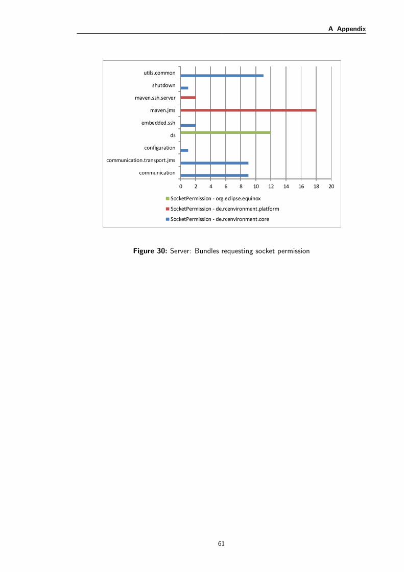
A Appendix
0 2 4 6 8 10 12 14 16 18 20
communication
communication.transport.jms
configuration
ds
embedded.ssh
maven.jms
maven.ssh.server
shutdown
utils.common
SocketPermission - org.eclipse.equinox
SocketPermission - de.rcenvironment.platform
SocketPermission - de.rcenvironment.core
Figure 30: Server: Bundles requesting socket permission
61

A Appendix
A.4 Final product backlog
Requirements are described as User stories. All user stories are planed for the implementationof sandbox prototype and initial receive the status TODO. User stories describing functionalrequirements are illustrated as Use cases in the Section 4.5. Each user story is prioritized byapplying the MusCoW method. The method has three categories: Must, Could and Wish.User stories rated with Must are essential to achieve the objective of implementing the sandboxprototype. The category Cloud includes user stories describing relevant features which are notnecessary for the success. The prototype is limited in the usability without those user stories.The implementation of user stories indicated with Wish are desirable. The prototype workswithout limitation, when those user stories are missing.
Table 10 shows the final product backlog. An additional column shows the status after thesandbox implementation for each user story. Usually, user stories may be in one of the followingstatus: TODO, IN PROCESS, TO VERIFY and DONE. In this case, only TODO and DONEare used to indicate the success of the prototype implementation. Therefore, a user storyreceiving the status TODO could not be implemented. On the other hand, DONE shows thatthe user story is successful implemented.
ID User Story Priority StatusInstruction
I1 Developer follows an instruction about specifying maximumbundle permissions
Must DONE
RCE start configurationR1 RCE starts with active security mechanism Must DONE
R2 RCE grants default permissions Must DONE
Data acquisitionD1 RCE loads all bundle names of workflow components Must DONE
D2 RCE loads granted permissions for a workflow component Must DONE
ConfigurationC1 RCE provides a dialog for configuring permissions for workflow
componentsMust DONE
C2 Administrator grants permission for a workflow component Must DONE
C3 Administrator edits granted permissions of a workflowcomponent
Must DONE
C4 Administrator revokes permission for a workflow component Must DONE
Workflow executionW1 RCE shows a dialog for undetermined permissions Must DONE
W2 Administrator makes a temporary decision for an undeterminedpermission
Must DONE
W3 Administrator makes permanent decision for an undeterminedpermission
Could TODO
Persistent permissionsP1 RCE saves granted permissions persistently Wish TODO
P2 RCE loads persistent permissions Wish TODO
Spike storiesS1 Research and describe Java Sandbox Model Must DONE
S2 Research and describe OSGi Sandbox Model Must DONE
S3 Research about OSGi Service Must DONE
Table 10: Final Product Backlog
62
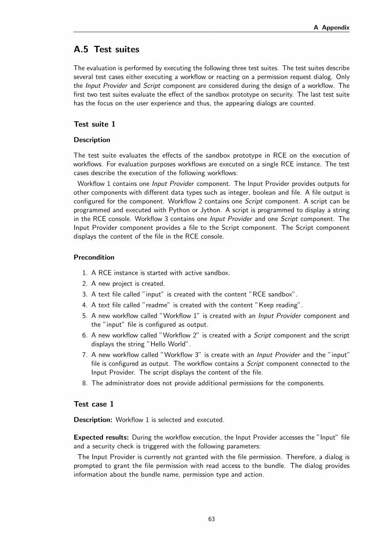
A Appendix
A.5 Test suites
The evaluation is performed by executing the following three test suites. The test suites describeseveral test cases either executing a workflow or reacting on a permission request dialog. Onlythe Input Provider and Script component are considered during the design of a workflow. Thefirst two test suites evaluate the effect of the sandbox prototype on security. The last test suitehas the focus on the user experience and thus, the appearing dialogs are counted.
Test suite 1
Description
The test suite evaluates the effects of the sandbox prototype in RCE on the execution ofworkflows. For evaluation purposes workflows are executed on a single RCE instance. The testcases describe the execution of the following workflows:
Workflow 1 contains one Input Provider component. The Input Provider provides outputs forother components with different data types such as integer, boolean and file. A file output isconfigured for the component. Workflow 2 contains one Script component. A script can beprogrammed and executed with Python or Jython. A script is programmed to display a stringin the RCE console. Workflow 3 contains one Input Provider and one Script component. TheInput Provider component provides a file to the Script component. The Script componentdisplays the content of the file in the RCE console.
Precondition
1. A RCE instance is started with active sandbox.
2. A new project is created.
3. A text file called ”input” is created with the content ”RCE sandbox”.
4. A text file called ”readme” is created with the content ”Keep reading”.
5. A new workflow called ”Workflow 1” is created with an Input Provider component andthe ”input” file is configured as output.
6. A new workflow called ”Workflow 2” is created with a Script component and the scriptdisplays the string ”Hello World”.
7. A new workflow called ”Workflow 3” is create with an Input Provider and the ”input”file is configured as output. The workflow contains a Script component connected to theInput Provider. The script displays the content of the file.
8. The administrator does not provide additional permissions for the components.
Test case 1
Description: Workflow 1 is selected and executed.
Expected results: During the workflow execution, the Input Provider accesses the ”Input” fileand a security check is triggered with the following parameters:
The Input Provider is currently not granted with the file permission. Therefore, a dialog isprompted to grant the file permission with read access to the bundle. The dialog providesinformation about the bundle name, permission type and action.
63
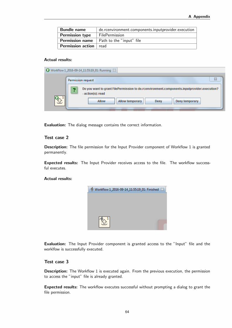
A Appendix
Bundle name de.rcenvironment.components.inputprovider.execution
Permission type FilePermission
Permission name Path to the ”input” file
Permission action read
Actual results:
Evaluation: The dialog message contains the correct information.
Test case 2
Description: The file permission for the Input Provider component of Workflow 1 is grantedpermanently.
Expected results: The Input Provider receives access to the file. The workflow success-ful executes.
Actual results:
Evaluation: The Input Provider component is granted access to the ”Input” file and theworklfow is successfully executed.
Test case 3
Description: The Workflow 1 is executed again. From the previous execution, the permissionto access the ”input” file is already granted.
Expected results: The workflow executes successful without prompting a dialog to grant thefile permission.
64
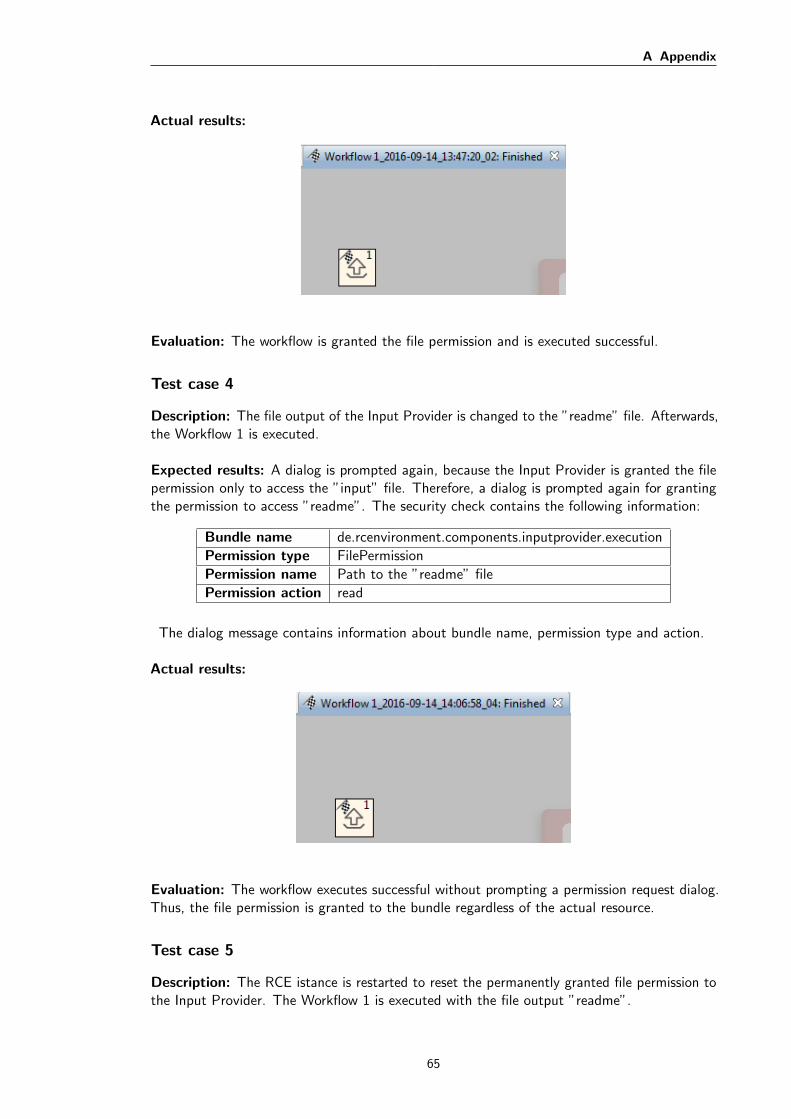
A Appendix
Actual results:
Evaluation: The workflow is granted the file permission and is executed successful.
Test case 4
Description: The file output of the Input Provider is changed to the ”readme” file. Afterwards,the Workflow 1 is executed.
Expected results: A dialog is prompted again, because the Input Provider is granted the filepermission only to access the ”input” file. Therefore, a dialog is prompted again for grantingthe permission to access ”readme”. The security check contains the following information:
Bundle name de.rcenvironment.components.inputprovider.execution
Permission type FilePermission
Permission name Path to the ”readme” file
Permission action read
The dialog message contains information about bundle name, permission type and action.
Actual results:
Evaluation: The workflow executes successful without prompting a permission request dialog.Thus, the file permission is granted to the bundle regardless of the actual resource.
Test case 5
Description: The RCE istance is restarted to reset the permanently granted file permission tothe Input Provider. The Workflow 1 is executed with the file output ”readme”.
65

A Appendix
Expected results: A permission request dialog is prompted with the same expected in-formation as described in Test Case 4.
Actual results:
Evaluation: The dialog is prompted and displays the correct information.
Test case 6
Description: The file permission for the Input Provider is permanently denied.
Expected results: The workflow fails, due to the missing file permission.
Actual results:
Evaluation: The workflow failed during the execution. An error occurred, because thepermission request dialog represents a condition and it is not satisfied. Therefore, the access tothe ”readme” file is denied.
Test case 7
Description: A general file permission is granted to the Input Provider by using the permissioncontrol dialog. The general file permission contains the following entries:
66
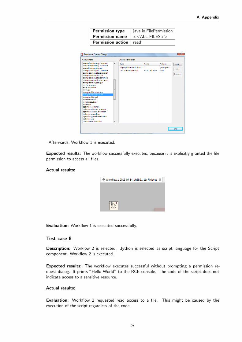
A Appendix
Permission type java.io.FilePermission
Permission name <<ALL FILES>>
Permission action read
Afterwards, Workflow 1 is executed.
Expected results: The workflow successfully executes, because it is explicitly granted the filepermission to access all files.
Actual results:
Evaluation: Workflow 1 is executed successfully.
Test case 8
Description: Worklow 2 is selected. Jython is selected as script language for the Scriptcomponent. Workflow 2 is executed.
Expected results: The workflow executes successful without prompting a permission re-quest dialog. It prints ”Hello World” to the RCE console. The code of the script does notindicate access to a sensitive resource.
Actual results:
Evaluation: Workflow 2 requested read access to a file. This might be caused by theexecution of the script regardless of the code.
67

A Appendix
Test case 9
Description: The file permission for the script execution is granted permanently. All follow-updialogs are necessary for the execution, therefore, they are granted permanently.
Expected results: After granting all permissions for the script execution, Workflow 2 ex-ecutes successful and prints ”Hello World” to the RCE console.
Actual results:
Evaluation: Six follow-up permission request dialogs appeared in the following order: Thebundle names start all with de.rcenvironment.components. After granting all 7 permissionrequests, Workflow 2 successfully executed and printed out ”Hello World” to the RCE console.
68

A Appendix
Bundle name Permission type Permission actionscript.execution.jython File permission read
script.execution File permission write
script.execution.jython File permission write
script.execution.jython Runtime permission
script.execution Runtime permission
script.execution File permission delete
Test case 10
Description: The script language of the Script component is changed to Python and Workflow2 is executed. Each permission request is granted permanently, because they are required forthe execution of the script.
Expected results: The Script component requests permission to execute the script withPython. Jython requested in total 7 permissions. Python may request around the same amountof permissions. After granting the missing permission, Workflow 2 finishes successful and prints”Hello World” to the console.
Actual results:
69
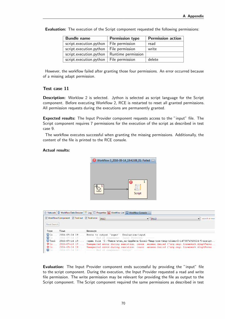
A Appendix
Evaluation: The execution of the Script component requested the following permissions:
Bundle name Permission type Permission actionscript.execution.python File permission read
script.execution.python File permission write
script.execution.python Runtime permission
script.execution.python File permission delete
However, the workflow failed after granting those four permissions. An error occurred becauseof a missing adapt permission.
Test case 11
Description: Worklow 2 is selected. Jython is selected as script language for the Scriptcomponent. Before executing Workflow 2, RCE is restarted to reset all granted permissions.All permission requests during the executions are permanently granted.
Expected results: The Input Provider component requests access to the ”input” file. TheScript component requires 7 permissions for the execution of the script as described in testcase 9.
The workflow executes successful when granting the missing permissions. Additionally, thecontent of the file is printed to the RCE console.
Actual results:
Evaluation: The Input Provider component ends successful by providing the ”input” fileto the script component. During the execution, the Input Provider requested a read and writefile permission. The write permission may be relevant for providing the file as output to theScript component. The Script component required the same permissions as described in test
70
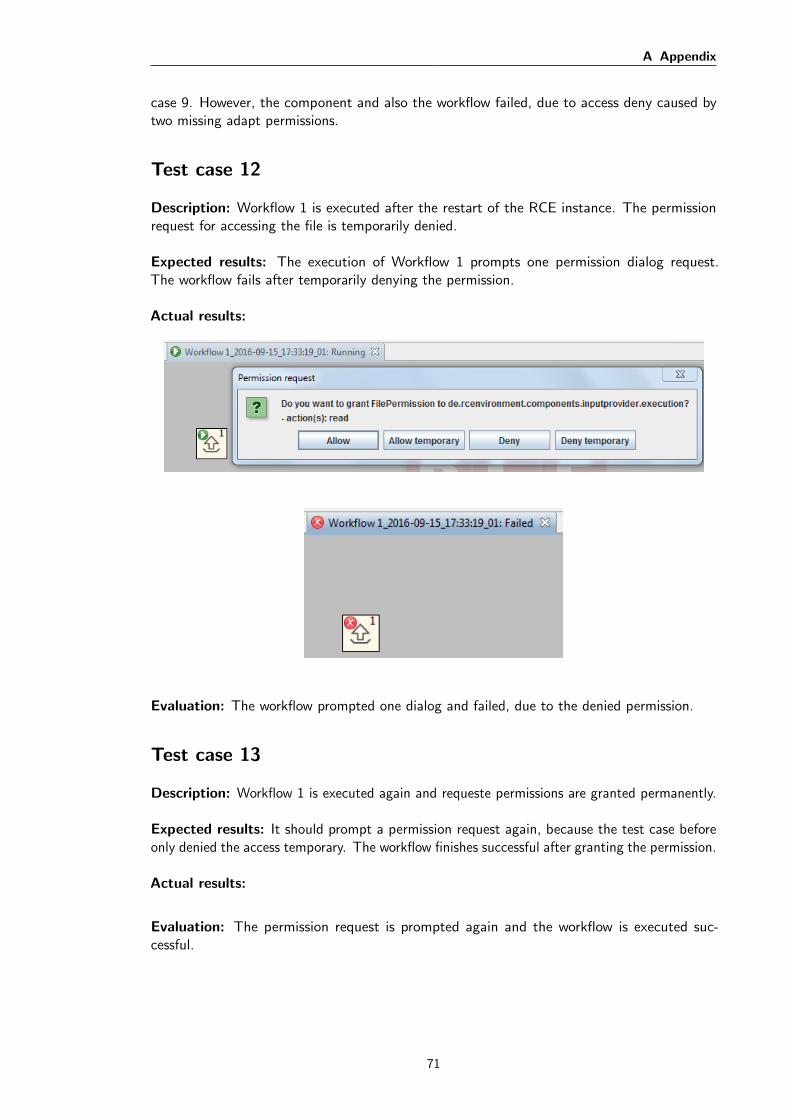
A Appendix
case 9. However, the component and also the workflow failed, due to access deny caused bytwo missing adapt permissions.
Test case 12
Description: Workflow 1 is executed after the restart of the RCE instance. The permissionrequest for accessing the file is temporarily denied.
Expected results: The execution of Workflow 1 prompts one permission dialog request.The workflow fails after temporarily denying the permission.
Actual results:
Evaluation: The workflow prompted one dialog and failed, due to the denied permission.
Test case 13
Description: Workflow 1 is executed again and requeste permissions are granted permanently.
Expected results: It should prompt a permission request again, because the test case beforeonly denied the access temporary. The workflow finishes successful after granting the permission.
Actual results:
Evaluation: The permission request is prompted again and the workflow is executed suc-cessful.
71
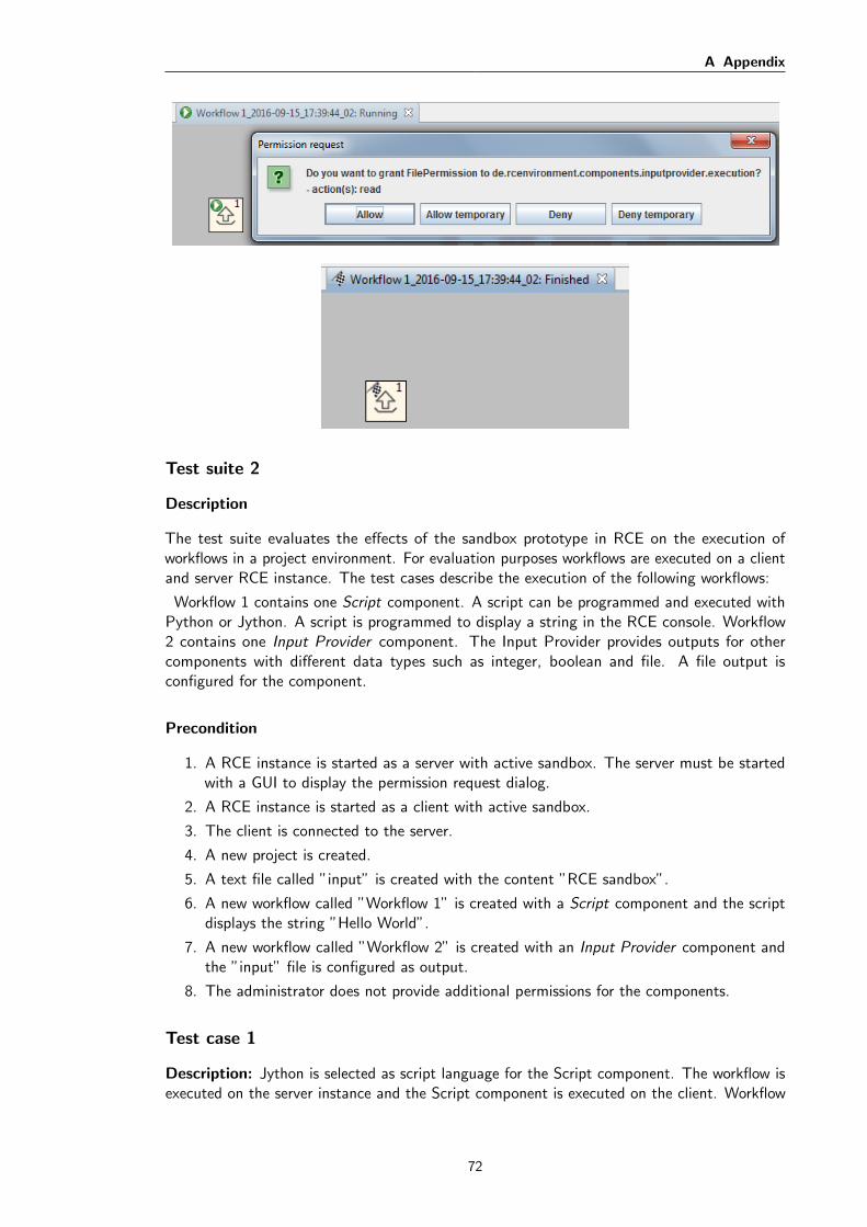
A Appendix
Test suite 2
Description
The test suite evaluates the effects of the sandbox prototype in RCE on the execution ofworkflows in a project environment. For evaluation purposes workflows are executed on a clientand server RCE instance. The test cases describe the execution of the following workflows:
Workflow 1 contains one Script component. A script can be programmed and executed withPython or Jython. A script is programmed to display a string in the RCE console. Workflow2 contains one Input Provider component. The Input Provider provides outputs for othercomponents with different data types such as integer, boolean and file. A file output isconfigured for the component.
Precondition
1. A RCE instance is started as a server with active sandbox. The server must be startedwith a GUI to display the permission request dialog.
2. A RCE instance is started as a client with active sandbox.
3. The client is connected to the server.
4. A new project is created.
5. A text file called ”input” is created with the content ”RCE sandbox”.
6. A new workflow called ”Workflow 1” is created with a Script component and the scriptdisplays the string ”Hello World”.
7. A new workflow called ”Workflow 2” is created with an Input Provider component andthe ”input” file is configured as output.
8. The administrator does not provide additional permissions for the components.
Test case 1
Description: Jython is selected as script language for the Script component. The workflow isexecuted on the server instance and the Script component is executed on the client. Workflow
72
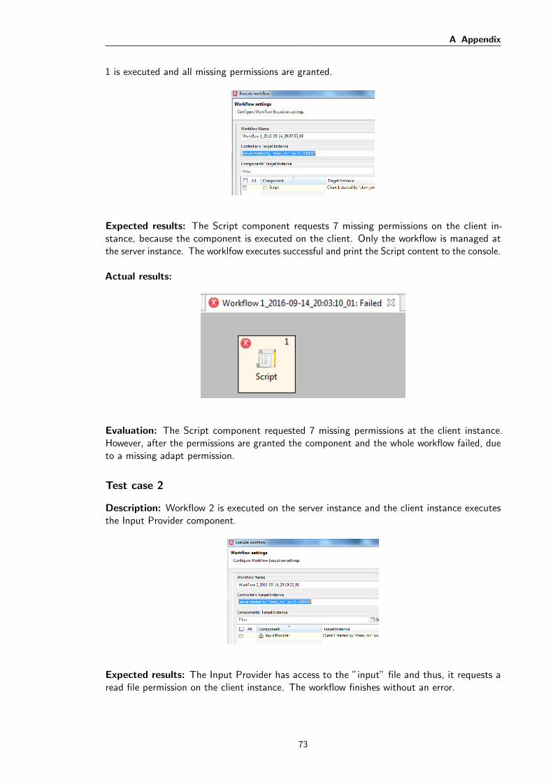
A Appendix
1 is executed and all missing permissions are granted.
Expected results: The Script component requests 7 missing permissions on the client in-stance, because the component is executed on the client. Only the workflow is managed atthe server instance. The worklfow executes successful and print the Script content to the console.
Actual results:
Evaluation: The Script component requested 7 missing permissions at the client instance.However, after the permissions are granted the component and the whole workflow failed, dueto a missing adapt permission.
Test case 2
Description: Workflow 2 is executed on the server instance and the client instance executesthe Input Provider component.
Expected results: The Input Provider has access to the ”input” file and thus, it requests aread file permission on the client instance. The workflow finishes without an error.
73

A Appendix
Actual results:
Evaluation: A permission request dialog is prompted for the Input Provider component.However, the workflow fails, because a runtime permission is missing.
Test case 3
Description: The RCE client instance is restarted and the Input Provider component is grantedwith full file and runtime permission. Afterwards, Workflow 2 is executed on the server and thecomponent on the client.
Expected results: The workflow executes without asking for a missing permission.
Actual results:
Evaluation: The workflow did not request the file permission. However, the workflow failswith a missing runtime permission. Even the runtime permission is explicitly granted to thecomponent.
74
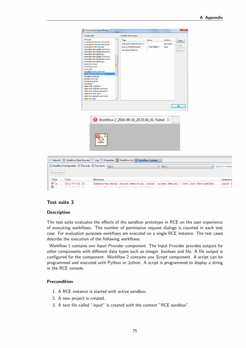
A Appendix
Test suite 3
Description
The test suite evaluates the effects of the sandbox prototype in RCE on the user experienceof executing workflows. The number of permission request dialogs is counted in each testcase. For evaluation purposes workflows are executed on a single RCE instance. The test casesdescribe the execution of the following workflows:
Workflow 1 contains one Input Provider component. The Input Provider provides outputs forother components with different data types such as integer, boolean and file. A file output isconfigured for the component. Workflow 2 contains one Script component. A script can beprogrammed and executed with Python or Jython. A script is programmed to display a stringin the RCE console.
Precondition
1. A RCE instance is started with active sandbox.
2. A new project is created.
3. A text file called ”input” is created with the content ”RCE sandbox”.
75
A Appendix
4. A new workflow called ”Workflow 1” is created with a Input Provider component andthe ”Input” file is configured as output.
5. A new workflow called ”Workflow 2” is created with a Script component and the scriptdisplays the string ”Hello World”.
6. The administrator does not provide additional permissions for the components.
Test case 1
Description: Workflow 1 is executed. All permission requests are granted permanently andthe appearing dialogs are counted.
Expected results: Input Provider requires a file permission access. One permission requestdialog is prompted and is accepted permanently. The workflow finished without prompting adialog again.
Expected number of dialogs: 1
Actual results: Actual number of dialogs: 1
Evaluation: The workflow is finished with prompting one dialog. The actual number ofdialogs is correct.
Test case 2
Description: Workflow 1 is executed after the RCE instance is restarted. All permissionrequests are granted temporarily and the appearing dialogs are counted.
Expected results: Input Provider requires a file permission access. All appearing dialogsare granted temporarily. Hence, the workflow may produce several permission request dialogsbefore finishing.
Expected number of dialogs: 1 or more
Actual results: Actual number of dialogs: 4
Evaluation: The Input Provider must access the file four times. Therefore, the dialogappears four times, because granting temporarily is only valid for one access.
Test case 3
Description: The administrator grants full file access to the Input Provider. Workflow 1 isexecuted.
Expected results: The workflow executes without prompting a permission request dialog.Input Provider is already granted with the file permission.
Expected number of dialogs: 0
Actual results: Actual number of dialogs: 0
Evaluation: The workflow executes without prompting one dialog.
76

A Appendix
Test case 4
Description: Jython is selected as script language and Workflow 2 is executed. All permissionrequests are granted permanently and the appearing dialogs are counted.
Expected results: The Script component requests 7 different permissions and each is grantedpermanently.
Expected number of dialogs: 7
Actual results: Actual number of dialogs: 7
Evaluation: The workflow is finished with prompting one dialog. The actual number ofdialogs is correct.
Test case 5
Description: Workflow 1 is executed after the RCE instance is restarted. Jython is still usedfor executing the script. All permission requests are granted temporarily and the appearingdialogs are counted.
Expected results: The Script component already accesses 7 different permissions. Eachcorresponding resource may be accessed several times. Hence, the dialog may be requestedmore than 7 times.
Expected number of dialogs: 7 or more
Actual results: Actual number of dialogs: more than 100
Evaluation: The actual number of dialogs indicate that the Script component performsa lot of accesses to protected resources like file access.
77