Embed Size (px)
Citation preview
IBM SAN Volume Controller
Model 2145-DH8 Hardware InstallationGuide
GC27-6490-04
IBM
NoteBefore using this information and the product it supports, read the following information:
v The general information in “Notices” on page 63
v The information in the “Safety and environmental notices” on page ix
v The information in the IBM Environmental Notices and User Guide (provided on a DVD)
This edition applies to IBM SAN Volume Controller and is valid until replaced by new editions.
This edition replaces GC27-6490-03.
© Copyright IBM Corporation 2014, 2015.US Government Users Restricted Rights – Use, duplication or disclosure restricted by GSA ADP Schedule Contractwith IBM Corp.
Contents
Figures . . . . . . . . . . . . . .. v
Tables . . . . . . . . . . . . . .. vii
Safety and environmental notices . .. ixSafety notices and labels . . . . . . . . .. ix
Caution notices for the SAN Volume Controller.. xDanger notices for SAN Volume Controller .. xiii
Special caution and safety notices. . . . . .. xviGeneral safety . . . . . . . . . . .. xviInspecting the SAN Volume Controller for unsafeconditions . . . . . . . . . . . . .. xxChecking the grounding of a SAN VolumeController. . . . . . . . . . . . .. xxiEmergency power-off shutdown . . . . .. xxiiHandling static-sensitive devices . . . . .. xxii
Environmental notices . . . . . . . . .. xxiii
About this guide . . . . . . . . .. xxvWho should use this guide . . . . . . . .. xxvEmphasis. . . . . . . . . . . . . .. xxvSAN Volume Controller library and relatedpublications . . . . . . . . . . . .. xxviHow to order IBM publications . . . . .. xxviiiRelated websites . . . . . . . . . .. xxviiiSending your comments . . . . . . . .. xxixHow to get information, help, and technicalassistance . . . . . . . . . . . . .. xxix
SAN Volume Controller initialinstallation overview . . . . . .. xxxiii
Chapter 1. Preparing to install the SANVolume Controller . . . . . . . . .. 1SAN Volume Controller operating environment. .. 1Rack cabinet physical location . . . . . . .. 2SAN Volume Controller 2145-DH8 front panelcontrols and indicators . . . . . . . . . .. 2SAN Volume Controller 2145-DH8operator-information panel . . . . . . . .. 4SAN Volume Controller 2145-DH8 rear-panelindicators . . . . . . . . . . . . . .. 6
Fibre Channel LEDs . . . . . . . . . .. 6AC, DC, and power-supply error LEDs . . .. 7Power, location, and system-error LEDs . . .. 8SAN Volume Controller 2145-DH8 Ethernet portLEDs . . . . . . . . . . . . . . .. 9
SAN Volume Controller 2145-DH8 connectors . .. 11SAN Volume Controller 2145-DH8 ports usedduring service procedures . . . . . . .. 12SAN Volume Controller 2145-DH8 unused ports 12SAN Volume Controller 2145-DH8 Fibre Channelport numbers . . . . . . . . . . . .. 13
Chapter 2. Installing the SAN VolumeController 2145-DH8 hardware . . .. 15Preparing for the SAN Volume Controller 2145-DH8hardware installation . . . . . . . . . .. 15Installing the SAN Volume Controller 2145-DH8 .. 18
Installation guidelines . . . . . . . . .. 19Installing the support rails for a SAN VolumeController 2145-DH8 . . . . . . . . .. 19Installing the cable management arm assemblyfor the SAN Volume Controller 2145-DH8 . .. 25Installing the SAN Volume Controller 2145-DH8in a rack . . . . . . . . . . . . .. 34Connecting the SAN Volume Controller2145-DH8 to the SAN and to the Ethernetnetwork . . . . . . . . . . . . .. 35Verifying the SAN Volume Controller 2145-DH8installation . . . . . . . . . . . .. 37
Chapter 3. Installing the SAN VolumeController 2145-24F expansionenclosure . . . . . . . . . . . .. 41Installing the support rails for the SAN VolumeController 2145-24F . . . . . . . . . . .. 41Installing the SAN Volume Controller 2145-24F in arack . . . . . . . . . . . . . . . .. 44Connecting the optional expansion enclosures . .. 46
Chapter 4. Initializing the SAN VolumeController 2145-DH8 system . . . .. 49Checking your web browser settings for themanagement GUI . . . . . . . . . . .. 49User name and password for system initialization 51Initializing the system by using the technician port 51Adding nodes to an existing clustered system . .. 53
Appendix A. Accessibility features forIBM SAN Volume Controller. . . . .. 55
Appendix B. Where to find theStatement of Limited Warranty . . .. 57
Appendix C. SAN Volume Controllerphysical installation planning . . . .. 59SAN Volume Controller 2145-DH8 environmentrequirements . . . . . . . . . . . . .. 59
Notices . . . . . . . . . . . . .. 63Trademarks . . . . . . . . . . . . .. 65Homologation statement . . . . . . . . .. 65Electronic emission notices . . . . . . . .. 65
Federal Communications Commission (FCC)statement . . . . . . . . . . . . .. 65Industry Canada compliance statement . . .. 66
© Copyright IBM Corp. 2014, 2015 iii
Australia and New Zealand Class A Statement 66European Union Electromagnetic CompatibilityDirective . . . . . . . . . . . . .. 66Germany Electromagnetic Compatibility Directive 66People's Republic of China Class A Statement .. 67Taiwan Class A compliance statement . . .. 68Taiwan Contact Information . . . . . . .. 68Japan VCCI Council Class A statement . . .. 68Japan Electronics and Information TechnologyIndustries Association Statement . . . . .. 68
Korean Communications Commission Class AStatement . . . . . . . . . . . . .. 69Russia Electromagnetic Interference Class AStatement . . . . . . . . . . . . .. 69
Index . . . . . . . . . . . . . .. 71
iv SAN Volume Controller: Model 2145-DH8 Hardware Installation Guide
Figures
1. SAN Volume Controller 2145-DH8 front panel 22. SAN Volume Controller 2145-DH8
operator-information panel . . . . . . .. 43. SAN Volume Controller 2145-DH8 rear-panel
indicators . . . . . . . . . . . .. 64. Fibre Channel LEDs . . . . . . . . .. 75. SAN Volume Controller 2145-DH8 AC, DC, and
power-error LEDs . . . . . . . . . .. 86. Power, location, and system-error LEDs . .. 87. Ethernet ports on the system board . . . .. 98. Ethernet port LEDs on the system board 109. Ethernet port LEDs on a 10 Gbps Ethernet
adapter . . . . . . . . . . . . .. 1010. Connectors on the rear of the SAN Volume
Controller 2145-DH8 . . . . . . . .. 1111. Power connector . . . . . . . . . .. 1112. SAN Volume Controller 2145-DH8 service
ports . . . . . . . . . . . . . .. 1213. SAN Volume Controller 2145-DH8 unused
Ethernet port . . . . . . . . . . .. 1214. Physical Fibre Channel port numbers with a
host interface adapter in slot 1 . . . . .. 1315. Physical Fibre Channel port numbers with a
host interface adapter in slot 2 . . . . .. 1316. Physical Fibre Channel port numbers with host
interface adapters in slots 1 and 2 . . . .. 1317. Physical Fibre Channel port numbers with host
interface adapters in slots 1, 2, and 5 . . .. 1418. Physical Fibre Channel port numbers with host
interface adapters in slots 1, 2, 3, and 5 . .. 1419. Parts provided for SAN Volume Controller
2145-DH8 hardware installation in a rack .. 1620. Identifying rack space . . . . . . . .. 2021. Opening the rear slide-rail hooks . . . .. 2122. Installing rear end of slide rail . . . . .. 2223. Opening the front slide rail latch . . . .. 2324. Aligning front of slide rail to rack front 2425. Installing front end of slide rail . . . . .. 25
26. Parts for installing the SAN Volume Controller2145-DH8 cable management arm assembly .. 25
27. Installing the cable-management support bar 2628. Connecting the cable management support bar
to the stop bracket . . . . . . . . .. 2729. Connecting the stop bracket to the slide rail 2830. Installing the cable management arm . . .. 2931. Closing the stop bracket . . . . . . .. 3032. Connecting and routing the cables . . . .. 3133. Securing the cables with hook-and-loop
fastener strap . . . . . . . . . . .. 3234. Installing the cable management arm on the
opposite side . . . . . . . . . . .. 3335. Securing the cable management arm and node 3336. Installing the front screws. . . . . . .. 3437. Installing the SAN Volume Controller
2145-DH8 node in the slide rails of the rack.. 3538. Raising the SAN Volume Controller 2145-DH8
locking levers of the slide rails of the rack .. 3539. Ethernet ports on the rear of the SAN Volume
Controller 2145-DH8 . . . . . . . .. 3640. 10 Gbps Ethernet ports. . . . . . . .. 3641. Fibre Channel ports . . . . . . . . .. 3742. SAN Volume Controller 2145-DH8 front panel 3843. SAN Volume Controller 2145-DH8
operator-information panel . . . . . .. 3944. Rack mounting rails and screws. . . . .. 4145. Installing the rail spring . . . . . . .. 4246. Hole locations in the front of the rack . . .. 4247. Opening the hinge brackets . . . . . .. 4348. Closing hinge brackets and installing rear
screw . . . . . . . . . . . . .. 4449. Inserting the enclosure . . . . . . . .. 4550. SAS cable connector orientation . . . . .. 4651. Connecting the SAS cables . . . . . .. 4852. SAN Volume Controller 2145-DH8 technician
port . . . . . . . . . . . . . .. 52
© Copyright IBM Corp. 2014, 2015 v
|||

vi SAN Volume Controller: Model 2145-DH8 Hardware Installation Guide
Tables
1. IBM websites for help, services, andinformation . . . . . . . . . . .. xxvi
2. SAN Volume Controller library . . . .. xxvi3. Other IBM publications . . . . . .. xxviii4. IBM documentation and related websites xxviii5. IBM websites for help, services, and
information . . . . . . . . . . .. xxix6. Link status values for Fibre Channel LEDs 77. Preventing the batteries from discharging 188. Default user name and password for the
management GUI . . . . . . . . .. 51
9. Node model names and software versionrequirements . . . . . . . . . . .. 53
10. Input-voltage requirements . . . . . .. 5911. Maximum power consumption . . . . .. 5912. Physical specifications . . . . . . . .. 6013. Dimensions and weight . . . . . . .. 6014. Additional space requirements . . . . .. 6015. Maximum heat output of each 2145-DH8 node 61
© Copyright IBM Corp. 2014, 2015 vii

viii SAN Volume Controller: Model 2145-DH8 Hardware Installation Guide
Safety and environmental notices
Review the safety notices, environmental notices, and electronic emission noticesfor IBM® SAN Volume Controller before you install and use the product.
Suitability for telecommunication environment: This product is not intended toconnect directly or indirectly by any means whatsoever to interfaces of publictelecommunications networks.
Here are examples of a caution and a danger notice:
CAUTION:A caution notice indicates the presence of a hazard that has the potential ofcausing moderate or minor personal injury. (C001)
DANGER
A danger notice indicates the presence of a hazard that has the potential ofcausing death or serious personal injury. (D002)
To find the translated text for a caution or danger notice:1. Look for the identification number at the end of each caution notice or each
danger notice. In the preceding examples, the numbers (C001) and (D002) arethe identification numbers.
2. Locate the IBM System Storage SAN Volume Controller Safety Notices with theuser publications that were provided with the SAN Volume Controllerhardware.
3. Find the matching identification number in the IBM System Storage SAN VolumeController Safety Notices. Then review the topics concerning the safety notices toensure that you are in compliance.
4. Optionally, read the multilingual safety instructions on the SAN VolumeController website. Go to www.ibm.com/storage/support/2145, search for SANVolume Controller, and click the documentation link.
Safety notices and labelsReview the safety notices and safety information labels before using this product.
To view a PDF file, you need Adobe Acrobat Reader. You can download it at nocharge from the Adobe website:
www.adobe.com/support/downloads/main.html
IBM Systems Safety Notices
This publication contains the safety notices for the IBM Systems products inEnglish and other languages. Anyone who plans, installs, operates, or services thesystem must be familiar with and understand the safety notices. Read the relatedsafety notices before you begin work.
© Copyright IBM Corp. 2014, 2015 ix
Note: The IBM System Safety Notices document is organized into two sections. Thedanger and caution notices without labels are organized alphabetically by languagein the “Danger and caution notices by language” section. The danger and cautionnotices that are accompanied with a label are organized by label reference numberin the “Labels” section.
Note: You can find and download the current IBM System Safety Notices bysearching for Publication number G229-9054 in the IBM Publications Center.
The following notices and statements are used in IBM documents. They are listedin order of decreasing severity of potential hazards.
Danger notice definitionA special note that emphasizes a situation that is potentially lethal orextremely hazardous to people.
Caution notice definitionA special note that emphasizes a situation that is potentially hazardous topeople because of some existing condition, or to a potentially dangeroussituation that might develop because of some unsafe practice.
Note: In addition to these notices, labels might be attached to the product to warnof potential hazards.
Finding translated notices
Each safety notice contains an identification number. You can use this identificationnumber to check the safety notice in each language.
To find the translated text for a caution or danger notice:1. In the product documentation, look for the identification number at the end of
each caution notice or each danger notice. In the following examples, thenumbers (D002) and (C001) are the identification numbers.DANGER
A danger notice indicates the presence of a hazard that has the potentialof causing death or serious personal injury. (D002)
CAUTION:A caution notice indicates the presence of a hazard that has the potential ofcausing moderate or minor personal injury. (C001)
2. After you download the IBM System Safety Notices document, open it.3. Under the language, find the matching identification number. Review the topics
about the safety notices to ensure that you are in compliance.
Note: This product was designed, tested, and manufactured to comply with IEC60950-1, and where required, to relevant national standards that are based on IEC60950-1.
Caution notices for the SAN Volume ControllerEnsure that you understand the caution notices for SAN Volume Controller.
Use the reference numbers in parentheses at the end of each notice, such as (C003)for example, to find the matching translated notice in IBM System Storage SANVolume Controller Safety Notices.
x SAN Volume Controller: Model 2145-DH8 Hardware Installation Guide
CAUTION:The battery contains lithium. To avoid possible explosion, do not burn or chargethe battery.
Do not: Throw or immerse into water, heat to more than 100°C (212°F), repair ordisassemble. (C003)
CAUTION:Electrical current from power, telephone, and communication cables can behazardous. To avoid personal injury or equipment damage, disconnect theattached power cords, telecommunication systems, networks, and modems beforeyou open the machine covers, unless instructed otherwise in the installation andconfiguration procedures. (26)
CAUTION:
v Do not install a unit in a rack where the internal rack ambient temperatureswill exceed the manufacturer's recommended ambient temperature for all yourrack-mounted devices.
v Do not install a unit in a rack where the air flow is compromised. Ensure thatair flow is not blocked or reduced on any side, front, or back of a unit usedfor air flow through the unit.
v Consideration should be given to the connection of the equipment to thesupply circuit so that overloading of the circuits does not compromise thesupply wiring or overcurrent protection. To provide the correct powerconnection to a rack, refer to the rating labels located on the equipment in therack to determine the total power requirement of the supply circuit.
v (For sliding drawers) Do not pull out or install any drawer or feature if therack stabilizer brackets are not attached to the rack. Do not pull out more thanone drawer at a time. The rack might become unstable if you pull out morethan one drawer at a time.
v (For fixed drawers) This drawer is a fixed drawer and must not be moved forservicing unless specified by the manufacturer. Attempting to move thedrawer partially or completely out of the rack might cause the rack to becomeunstable or cause the drawer to fall out of the rack.
(R001 part 2 of 2)
Safety and environmental notices xi
CAUTION:Removing components from the upper positions in the rack cabinet improvesrack stability during a relocation. Follow these general guidelines whenever yourelocate a populated rack cabinet within a room or building.
v Reduce the weight of the rack cabinet by removing equipment starting at thetop of the rack cabinet. When possible, restore the rack cabinet to theconfiguration of the rack cabinet as you received it. If this configuration is notknown, you must observe the following precautions.
– Remove all devices in the 32U position and above.
– Ensure that the heaviest devices are installed in the bottom of the rackcabinet.
– Ensure that there are no empty U-levels between devices installed in therack cabinet below the 32U level.
v If the rack cabinet you are relocating is part of a suite of rack cabinets, detachthe rack cabinet from the suite.
v If the rack cabinet you are relocating was supplied with removable outriggersthey must be reinstalled before the cabinet is relocated.
v Inspect the route that you plan to take to eliminate potential hazards.
v Verify that the route that you choose can support the weight of the loadedrack cabinet. Refer to the documentation that comes with your rack cabinet forthe weight of a loaded rack cabinet.
v Verify that all door openings are at least 760 x 230 mm (30 x 80 in.).
v Ensure that all devices, shelves, drawers, doors, and cables are secure.
v Ensure that the four leveling pads are raised to their highest position.
v Ensure that there is no stabilizer bracket installed on the rack cabinet duringmovement.
v Do not use a ramp inclined at more than 10 degrees.
v When the rack cabinet is in the new location, complete the following steps:
– Lower the four leveling pads.
– Install stabilizer brackets on the rack cabinet.
– If you removed any devices from the rack cabinet, repopulate the rackcabinet from the lowest position to the highest position.
v If a long-distance relocation is required, restore the rack cabinet to theconfiguration of the rack cabinet as you received it. Pack the rack cabinet inthe original packaging material, or equivalent. Also lower the leveling pads toraise the casters off the pallet and bolt the rack cabinet to the pallet.
(R002)
CAUTION:
v Rack is not intended to serve as an enclosure and does not provide anydegrees of protection required of enclosures.
v It is intended that equipment installed within this rack will have its ownenclosure. (R005).
CAUTION:Tighten the stabilizer brackets until they are flush against the rack. (R006)
CAUTION:Use safe practices when lifting. (R007)
xii SAN Volume Controller: Model 2145-DH8 Hardware Installation Guide
CAUTION:Do not place any object on top of a rack-mounted device unless thatrack-mounted device is intended for use as a shelf. (R008)
CAUTION:If the rack is designed to be coupled to another rack only the same model rackshould be coupled together with another same model rack. (R009)
Danger notices for SAN Volume ControllerEnsure that you are familiar with the danger notices for SAN Volume Controller.
Use the reference numbers in parentheses at the end of each notice, such as (C003)for example, to find the matching translated notice in IBM System Storage SANVolume Controller Safety Notices.
Safety and environmental notices xiii
DANGER
When working on or around the system, observe the following precautions:
Electrical voltage and current from power, telephone, and communicationcables are hazardous. To avoid a shock hazard:
v If IBM supplied a power cord(s), connect power to this unit only with theIBM provided power cord. Do not use the IBM provided power cord forany other product.
v Do not open or service any power supply assembly.
v Do not connect or disconnect any cables or perform installation,maintenance, or reconfiguration of this product during an electrical storm.
v The product might be equipped with multiple power cords. To remove allhazardous voltages, disconnect all power cords.
v Connect all power cords to a properly wired and grounded electrical outlet.Ensure that the outlet supplies proper voltage and phase rotation accordingto the system rating plate.
v Connect any equipment that will be attached to this product to properlywired outlets.
v When possible, use one hand only to connect or disconnect signal cables.
v Never turn on any equipment when there is evidence of fire, water, orstructural damage.
v Disconnect the attached power cords, telecommunications systems,networks, and modems before you open the device covers, unlessinstructed otherwise in the installation and configuration procedures.
v Connect and disconnect cables as described in the following procedureswhen installing, moving, or opening covers on this product or attacheddevices.
To disconnect:
1. Turn off everything (unless instructed otherwise).
2. Remove the power cords from the outlets.
3. Remove the signal cables from the connectors.
4. Remove all cables from the devices.
To connect:
1. Turn off everything (unless instructed otherwise).
2. Attach all cables to the devices.
3. Attach the signal cables to the connectors.
4. Attach the power cords to the outlets.
5. Turn on the devices.
v Sharp edges, corners and joints might be present in and around the system.Use care when handling equipment to avoid cuts, scrapes and pinching.(D005)
DANGER
Heavy equipment–personal injury or equipment damage might result ifmishandled. (D006)
DANGER
xiv SAN Volume Controller: Model 2145-DH8 Hardware Installation Guide
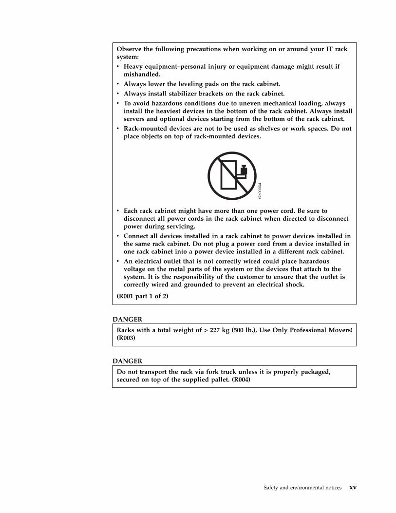
Observe the following precautions when working on or around your IT racksystem:
v Heavy equipment–personal injury or equipment damage might result ifmishandled.
v Always lower the leveling pads on the rack cabinet.
v Always install stabilizer brackets on the rack cabinet.
v To avoid hazardous conditions due to uneven mechanical loading, alwaysinstall the heaviest devices in the bottom of the rack cabinet. Always installservers and optional devices starting from the bottom of the rack cabinet.
v Rack-mounted devices are not to be used as shelves or work spaces. Do notplace objects on top of rack-mounted devices.
v Each rack cabinet might have more than one power cord. Be sure todisconnect all power cords in the rack cabinet when directed to disconnectpower during servicing.
v Connect all devices installed in a rack cabinet to power devices installed inthe same rack cabinet. Do not plug a power cord from a device installed inone rack cabinet into a power device installed in a different rack cabinet.
v An electrical outlet that is not correctly wired could place hazardousvoltage on the metal parts of the system or the devices that attach to thesystem. It is the responsibility of the customer to ensure that the outlet iscorrectly wired and grounded to prevent an electrical shock.
(R001 part 1 of 2)
DANGER
Racks with a total weight of > 227 kg (500 lb.), Use Only Professional Movers!(R003)
DANGER
Do not transport the rack via fork truck unless it is properly packaged,secured on top of the supplied pallet. (R004)
Safety and environmental notices xv
DANGER
Main Protective Earth (Ground):
This symbol is marked on the frame of the rack.
The PROTECTIVE EARTHING CONDUCTORS should be terminated at thatpoint. A recognized or certified closed loop connector (ring terminal) shouldbe used and secured to the frame with a lock washer using a bolt or stud.The connector should be properly sized to be suitable for the bolt or stud, thelocking washer, the rating for the conducting wire used, and the consideredrating of the breaker. The intent is to ensure the frame is electrically bondedto the PROTECTIVE EARTHING CONDUCTORS. The hole that the bolt orstud goes into where the terminal conductor and the lock washer contactshould be free of any non-conductive material to allow for metal to metalcontact. All PROTECTIVE EARTHING CONDUCTORS should terminate at
this main protective earthing terminal or at points marked with . (R010)
Special caution and safety noticesThis information describes special safety notices that apply to the SAN VolumeController. These notices are in addition to the standard safety notices suppliedand address specific issues relevant to the equipment provided.
General safetyWhen you service the SAN Volume Controller, follow general safety guidelines.
Use the following general rules to ensure safety to yourself and others.v Observe good housekeeping in the area where the devices are kept during and
after maintenance.v Follow the guidelines when lifting any heavy object:
1. Ensure that you can stand safely without slipping.2. Distribute the weight of the object equally between your feet.3. Use a slow lifting force. Never move suddenly or twist when you attempt to
lift.4. Lift by standing or by pushing up with your leg muscles; this action removes
the strain from the muscles in your back. Do not attempt to lift any objects thatweigh more than 18 kg (40 lb) or objects that you think are too heavy for you.
v Do not perform any action that causes a hazard or makes the equipment unsafe.v Before you start the device, ensure that service representatives and other
personnel are not in a hazardous position.v Place removed covers and other parts in a safe place, away from all personnel,
while you are servicing the unit.v Keep your tool case away from walk areas so that other people cannot trip over
it.v Do not wear loose clothing that can be trapped in the moving parts of a device.
Ensure that your sleeves are fastened or rolled up above your elbows. If yourhair is long, fasten it.
xvi SAN Volume Controller: Model 2145-DH8 Hardware Installation Guide
v Insert the ends of your necktie or scarf inside clothing or fasten it with anonconducting clip, approximately 8 cm (3 in.) from the end.
v Do not wear jewelry, chains, metal-frame eyeglasses, or metal fasteners for yourclothing.
Remember: Metal objects are good electrical conductors.v Wear safety glasses when you are hammering, drilling, soldering, cutting wire,
attaching springs, using solvents, or working in any other conditions that mightbe hazardous to your eyes.
v After service, reinstall all safety shields, guards, labels, and ground wires.Replace any safety device that is worn or defective.
v Reinstall all covers correctly after you have finished servicing the unit.
Safety and environmental notices xvii
Electrical safetyObserve these rules when working on electrical equipment.
DANGER
When working on or around the system, observe the following precautions:
Electrical voltage and current from power, telephone, and communicationcables are hazardous. To avoid a shock hazard:
v Connect power to this unit only with the IBM provided power cord. Do notuse the IBM provided power cord for any other product.
v Do not open or service any power supply assembly.
v Do not connect or disconnect any cables or perform installation,maintenance, or reconfiguration of this product during an electrical storm.
v The product might be equipped with multiple power cords. To remove allhazardous voltages, disconnect all power cords.
v Connect all power cords to a properly wired and grounded electrical outlet.Ensure that the outlet supplies proper voltage and phase rotation accordingto the system rating plate.
v Connect any equipment that will be attached to this product to properlywired outlets.
v When possible, use one hand only to connect or disconnect signal cables.
v Never turn on any equipment when there is evidence of fire, water, orstructural damage.
v Disconnect the attached power cords, telecommunications systems,networks, and modems before you open the device covers, unlessinstructed otherwise in the installation and configuration procedures.
v Connect and disconnect cables as described in the following procedureswhen installing, moving, or opening covers on this product or attacheddevices.
To disconnect:
1. Turn off everything (unless instructed otherwise).
2. Remove the power cords from the outlets.
3. Remove the signal cables from the connectors.
4. Remove all cables from the devices.
To connect:
1. Turn off everything (unless instructed otherwise).
2. Attach all cables to the devices.
3. Attach the signal cables to the connectors.
4. Attach the power cords to the outlets.
5. Turn on the devices.
v Sharp edges, corners and joints may be present in and around the system.Use care when handling equipment to avoid cuts, scrapes and pinching.
(D005)
Important: Use only approved tools and test equipment. Some hand tools havehandles covered with a soft material that does not insulate you when workingwith live electrical currents. Many customers have, near their equipment, rubber
xviii SAN Volume Controller: Model 2145-DH8 Hardware Installation Guide

floor mats that contain small conductive fibers to decrease electrostatic discharges.Do not use this type of mat to protect yourself from electrical shock.v Find the room emergency power-off (EPO) switch, disconnecting switch, or
electrical outlet. If an electrical accident occurs, you can then operate the switchor unplug the power cord quickly.
v Do not work alone under hazardous conditions or near equipment that hashazardous voltages.
v Disconnect all power before the following activities:– Performing a mechanical inspection– Working near power supplies– Removing or installing main units
v Before you start to work on the unit, unplug the power cord. If you cannotunplug it, ask the customer to power off the wall box that supplies power to thedevice and to lock the wall box in the off position.
v If you need to work on a device that has exposed electrical circuits, observe thefollowing precautions:– Ensure that another person, familiar with the power-off controls, is near you.
Remember: Another person must be there to switch off the power, ifnecessary.
– Use only one hand when working with electrical equipment that has thepower turned on; keep the other hand in your pocket or behind your back.
Remember: There must be a complete circuit to cause electrical shock. Byobserving the previous rule, you might prevent a current from passingthrough your body.
– When using testers, set the controls correctly and use the approved probeleads and accessories for that tester.
– Stand on suitable rubber mats (obtained locally, if necessary) to insulate youfrom grounds such as metal floor strips and machine frames.
Observe the special safety precautions when you work with very high voltages;these instructions are in the safety sections of maintenance information. Useextreme care when measuring high voltages.
v Regularly inspect and maintain your electrical hand tools for safe operationalcondition.
v Do not use worn or broken tools and testers.v Never assume that power has been disconnected from a circuit. First, check that
power has been powered off.v Always look carefully for possible hazards in your work area. Examples of these
hazards are moist floors, nongrounded power extension cables, power surges,and missing safety grounds.
v Do not touch live electrical circuits with the reflective surface of a plastic dentalmirror. The surface is conductive; such touching can cause personal injury anddevice damage.
v Do not service the following parts with the power on when they are removedfrom their normal operating places in a device. (This practice ensures correctgrounding of the units.)– Power supply units– Pumps– Blowers and fans
Safety and environmental notices xix
– Motor generators– And similar units
v If an electrical accident occurs:– Use caution; do not become a victim yourself.– Switch off power.– Send another person to get medical aid.
Inspecting the SAN Volume Controller for unsafe conditionsUse caution when working in any potential safety hazardous situation that is notcovered in the safety checks. If unsafe conditions are present, determine howserious the hazards are and whether you can continue before you correct theproblem.
Before you begin
Before you start the safety inspection, make sure that the power is off, and that thepower cord is disconnected.
About this task
Each device has required safety items installed to protect users and IBM servicepersonnel from injury. This guide addresses only those items.
Important: Good judgment must also be used to identify potential safety hazardsdue to the attachment of non-IBM features or options not covered by thisinspection guide.
If any unsafe conditions are present, you must determine how serious the apparenthazard could be and whether you can continue without first correcting theproblem. For example, consider the following conditions and their potential safetyhazards:
Electrical hazards (especially primary power)Primary voltage on the frame can cause serious or lethal electrical shock.
Explosive hazardsA damaged CRT face or a bulging capacitor can cause serious injury.
Mechanical hazardsLoose or missing items (for example, nuts and screws) can cause seriousinjury.
To inspect each SAN Volume Controller node for unsafe conditions, perform thefollowing steps. If necessary, see any suitable safety publications.
Procedure1. Turn off SAN Volume Controller and disconnect the power cord.2. Check the frame for damage (loose, broken, or sharp edges).3. Check the power cables using the following steps:
a. Ensure that the third-wire ground connector is in good condition. Use ameter to check that the third-wire ground continuity is 0.1 ohm or lessbetween the external ground pin and the frame ground.
b. Ensure that the power cord is the appropriate type, as specified in the partslistings.
xx SAN Volume Controller: Model 2145-DH8 Hardware Installation Guide
c. Ensure that the insulation is not worn or damaged.4. Check for any obvious nonstandard changes, both inside and outside the unit.
Use good judgment about the safety of any such changes.5. Check inside SAN Volume Controller for any obvious unsafe conditions, such
as metal particles, contamination, water or other fluids, or marks ofoverheating, fire, or smoke damage.
6. Check for worn, damaged, or pinched cables.7. Ensure that the voltage that is specified on the product-information label
matches the specified voltage of the electrical power outlet. If necessary, verifythe voltage.
8. Inspect the power-supply assemblies and check that the fasteners (screws orrivets) in the cover of the power-supply unit have not been removed ordisturbed.
9. Before connecting SAN Volume Controller to the storage area network (SAN),check the grounding of the network switch.
External device checkEnsure that you complete an external device check before you install or serviceSAN Volume Controller.
Procedure
To conduct an external device check, complete the following steps.1. Verify that all external covers are present and are not damaged.2. Ensure that all latches and hinges are in the correct operating condition.3. Check the power cords for damage.4. Check the external signal cables for damage.5. Check the cover for sharp edges, damage, or alterations that expose the internal
parts of the device.6. Correct any problems that you find.
Internal device checksEnsure that you complete an internal device check before you install or serviceSAN Volume Controller.
About this task
To conduct the internal device check, perform the following steps:
Procedure1. Check for any non-IBM changes that might have been made to the device. If
any are present, obtain the “Non-IBM Alteration Attachment Survey,” formnumber R009, from the IBM branch office. Complete the form and return it tothe branch office.
2. Check the condition of the inside of the device for any metal or othercontaminants, or any indications of water, other fluid, fire, or smoke damage.
3. Check for any obvious mechanical problems, such as loose components.4. Check any exposed cables and connectors for wear, cracks, or pinching.
Checking the grounding of a SAN Volume ControllerEnsure that you understand how to check the grounding of a SAN VolumeController.
Safety and environmental notices xxi
About this task
To test the grounding of a SAN Volume Controller node: Follow the steps for theSAN Volume Controller configuration that you are using. Before you start, confirmthat you know the SAN Volume Controller model type. Determine the location ofthe signal cables that are attached to the SAN Volume Controller.
When you are asked to test the grounding continuity, use your local procedures toinitiate the test. The test is successful if the measured resistance is 0.1 ohm or less.
Attention: Some electrical circuits can be damaged if the external signal cablesare present at the SAN Volume Controller while it is undergoing a grounding test.
Procedure1. Ensure that the SAN Volume Controller node is powered off. See MAP 5350:
Powering off a SAN Volume Controller node in the IBM SAN Volume ControllerTroubleshooting Guide.
2. Disconnect all signal cables from the SAN Volume Controller node, whichincludes the following cables:v The Fibre Channel cablesv The Ethernet cable or cables
3. Disconnect the power cable from the site power-distribution unit.4. Disconnect both input power leads from the site power distribution units.5. Test the grounding continuity between a conductive area on the SAN Volume
Controller frame and the ground pin on the plug of each input-power cable.6. After you have completed testing the grounding continuity, initiate one of the
following procedures, depending on the outcome of the test.v If the test is successful, reconnect any cables that were removed, and power
on any SAN Volume Controller nodes that were powered off.v If the test was not successful, ensure that all cables are securely connected. If
the test still fails, test the individual system components. Before you test theindividual components, remove all cables from the components. If anycomponent test fails, replace the component. After each component has beentested and the failing ones have been replaced, repeat the complete systemtest by returning to step 1.
v Test the SAN Volume Controller node, from the frame to the ground pin ofthe input power receptacle.
Emergency power-off shutdownThe SAN Volume Controller supports emergency power-off (EPO) shutdowns.
Handling static-sensitive devicesEnsure that you understand how to handle devices that are sensitive to staticelectricity.
Attention: Static electricity can damage electronic devices and your system. Toavoid damage, keep static-sensitive devices in their static-protective bags until youare ready to install them.
To reduce the possibility of electrostatic discharge, observe the followingprecautions:
xxii SAN Volume Controller: Model 2145-DH8 Hardware Installation Guide
v Limit your movement. Movement can cause static electricity to build up aroundyou.
v Handle the device carefully, holding it by its edges or frame.v Do not touch solder joints, pins, or exposed printed circuitry.v Do not leave the device where others can handle and possibly damage the
device.v While the device is still in its antistatic bag, touch it to an unpainted metal part
of the system unit for at least two seconds. (This action removes static electricityfrom the package and from your body.)
v Remove the device from its package and install it directly into your SANVolume Controller, without putting it down. If it is necessary to put the devicedown, place it onto its static-protective bag. (If your device is an adapter, place itcomponent-side up.) Do not place the device onto the cover of the SAN VolumeController or onto a metal table.
v Take additional care when you handle devices during cold weather. Indoorhumidity tends to decrease in cold weather, causing an increase in staticelectricity.
Environmental noticesThis information contains all of the required environmental notices for IBMSystems products in English and other languages.
The IBM Systems Environmental Notices (http://ibm.co/1fBgWFI) informationincludes statements on limitations, product information, product recycling anddisposal, battery information, flat panel display, refrigeration and water-coolingsystems, external power supplies, and safety data sheets.
Safety and environmental notices xxiii

xxiv SAN Volume Controller: Model 2145-DH8 Hardware Installation Guide
About this guide
This guide describes the SAN Volume Controller 2145-DH8 node and the SANVolume Controller 2145-24F expansion enclosure, and provides detailed installationinstructions.
Use this guide to perform the following tasks:v Install a new SAN Volume Controller system or extend an existing system.v Install one or more SAN Volume Controller nodes and SAN Volume Controller
expansion enclosures.v Connect SAN Volume Controller components to a SAN.v Manage connections to an Ethernet network.v Verify the completeness of a SAN Volume Controller installation.
The topics within this book provide conceptual, planning, and installationinformation for the SAN Volume Controller hardware model that was ordered.
Who should use this guideThe intended audience for this guide is the IBM service representative.
This guide should be read by the IBM service representative who is responsible forthe initial installation of the SAN Volume Controller.
After the IBM service representative has installed the SAN Volume Controllerhardware, use the Initialization GUI presented in a web browser of any computerthat is directly connected to the technician port to install any additional softwareand to configure the system.
EmphasisDifferent typefaces are used in this guide to show emphasis.
The following typefaces are used to show emphasis:
Boldface Text in boldface represents menu items.
Bold monospace Text in bold monospace represents commandnames.
Italics Text in italics is used to emphasize a word.In command syntax, it is used for variablesfor which you supply actual values, such asa default directory or the name of a system.
Monospace Text in monospace identifies the data orcommands that you type, samples ofcommand output, examples of program codeor messages from the system, or names ofcommand flags, parameters, arguments, andname-value pairs.
© Copyright IBM Corp. 2014, 2015 xxv

SAN Volume Controller library and related publicationsProduct manuals, other publications, and websites contain information that relatesto SAN Volume Controller.
IBM Knowledge Center for SAN Volume Controller
The information collection in the IBM Knowledge Center contains all of theinformation that is required to install, configure, and manage the system. Theinformation collection in the IBM Knowledge Center is updated between productreleases to provide the most current documentation. The information collection isavailable at the following website:
publib.boulder.ibm.com/infocenter/svc/ic/index.jsp
SAN Volume Controller library
Unless otherwise noted, the publications in the library are available in Adobeportable document format (PDF) from a website.
www.ibm.com/e-business/linkweb/publications/servlet/pbi.wss
Click Search for publications to find the online publications you are interested in,and then view or download the publication by clicking the appropriate item.
Table 1 lists websites where you can find help, services, and more information.
Table 1. IBM websites for help, services, and information
Website Address
Directory of worldwide contacts http://www.ibm.com/planetwide
Support for SAN Volume Controller (2145) www.ibm.com/storage/support/2145
Support for IBM System Storage® and IBM TotalStorageproducts
www.ibm.com/storage/support/
Each of the PDF publications in the Table 2 library is also available in the IBMKnowledge Center by clicking the number in the “Order number” column:
Table 2. SAN Volume Controller library
Title Description Order number
IBM SAN Volume ControllerModel 2145-DH8 HardwareInstallation Guide
The guide provides theinstructions that the IBMservice representative uses toinstall the hardware for SANVolume Controller model2145-DH8.
IBM System Storage SANVolume Controller Model2145-CG8 HardwareInstallation Guide
The guide provides theinstructions that the IBMservice representative uses toinstall the hardware for SANVolume Controller model2145-CG8.
xxvi SAN Volume Controller: Model 2145-DH8 Hardware Installation Guide
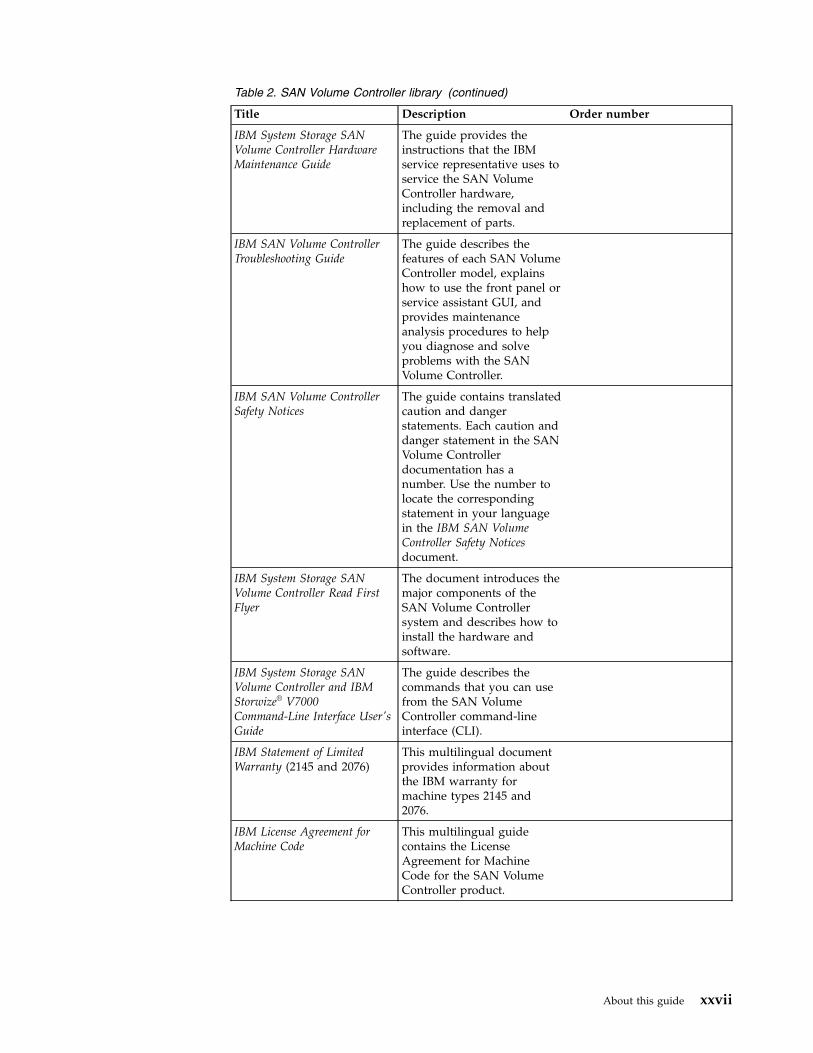
Table 2. SAN Volume Controller library (continued)
Title Description Order number
IBM System Storage SANVolume Controller HardwareMaintenance Guide
The guide provides theinstructions that the IBMservice representative uses toservice the SAN VolumeController hardware,including the removal andreplacement of parts.
IBM SAN Volume ControllerTroubleshooting Guide
The guide describes thefeatures of each SAN VolumeController model, explainshow to use the front panel orservice assistant GUI, andprovides maintenanceanalysis procedures to helpyou diagnose and solveproblems with the SANVolume Controller.
IBM SAN Volume ControllerSafety Notices
The guide contains translatedcaution and dangerstatements. Each caution anddanger statement in the SANVolume Controllerdocumentation has anumber. Use the number tolocate the correspondingstatement in your languagein the IBM SAN VolumeController Safety Noticesdocument.
IBM System Storage SANVolume Controller Read FirstFlyer
The document introduces themajor components of theSAN Volume Controllersystem and describes how toinstall the hardware andsoftware.
IBM System Storage SANVolume Controller and IBMStorwize® V7000Command-Line Interface User'sGuide
The guide describes thecommands that you can usefrom the SAN VolumeController command-lineinterface (CLI).
IBM Statement of LimitedWarranty (2145 and 2076)
This multilingual documentprovides information aboutthe IBM warranty formachine types 2145 and2076.
IBM License Agreement forMachine Code
This multilingual guidecontains the LicenseAgreement for MachineCode for the SAN VolumeController product.
About this guide xxvii

Other IBM publications
Table 3 lists an IBM publication that contains information that is related to SANVolume Controller.
Table 3. Other IBM publications
Title Description Order number
IBM System Storage MultipathSubsystem Device DriverUser's Guide
The guide describes the IBMSystem Storage MultipathSubsystem Device Driver for IBMSystem Storage products andhow to use it with the SANVolume Controller.
GC52-1309
IBM documentation and related websites
Table 4 lists websites that provide publications and other information about theSAN Volume Controller or related products or technologies. The IBM Redbooks®
publications provide positioning and value guidance, installation andimplementation experiences, solution scenarios, and step-by-step procedures forvarious products.
Table 4. IBM documentation and related websites
Website Address
IBM Publications Center www.ibm.com/e-business/linkweb/publications/servlet/pbi.wss
IBM Redbooks publications www.redbooks.ibm.com/
Related accessibility information
To view a PDF file, you need Adobe Reader, which can be downloaded from theAdobe website:
www.adobe.com/support/downloads/main.html
How to order IBM publicationsThe IBM Publications Center is a worldwide central repository for IBM productpublications and marketing material.
The IBM Publications Center offers customized search functions to help you findthe publications that you need. Some publications are available for you to view ordownload at no charge. You can also order publications. The publications centerdisplays prices in your local currency. You can access the IBM Publications Centerthrough the following website:
www.ibm.com/e-business/linkweb/publications/servlet/pbi.wss
Related websitesThe following websites provide information about SAN Volume Controller orrelated products or technologies:
Type of information Website
xxviii SAN Volume Controller: Model 2145-DH8 Hardware Installation Guide
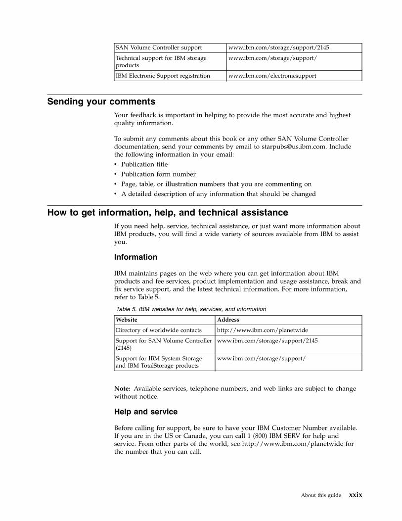
SAN Volume Controller support www.ibm.com/storage/support/2145
Technical support for IBM storageproducts
www.ibm.com/storage/support/
IBM Electronic Support registration www.ibm.com/electronicsupport
Sending your commentsYour feedback is important in helping to provide the most accurate and highestquality information.
To submit any comments about this book or any other SAN Volume Controllerdocumentation, send your comments by email to [email protected]. Includethe following information in your email:v Publication titlev Publication form numberv Page, table, or illustration numbers that you are commenting onv A detailed description of any information that should be changed
How to get information, help, and technical assistanceIf you need help, service, technical assistance, or just want more information aboutIBM products, you will find a wide variety of sources available from IBM to assistyou.
Information
IBM maintains pages on the web where you can get information about IBMproducts and fee services, product implementation and usage assistance, break andfix service support, and the latest technical information. For more information,refer to Table 5.
Table 5. IBM websites for help, services, and information
Website Address
Directory of worldwide contacts http://www.ibm.com/planetwide
Support for SAN Volume Controller(2145)
www.ibm.com/storage/support/2145
Support for IBM System Storageand IBM TotalStorage products
www.ibm.com/storage/support/
Note: Available services, telephone numbers, and web links are subject to changewithout notice.
Help and service
Before calling for support, be sure to have your IBM Customer Number available.If you are in the US or Canada, you can call 1 (800) IBM SERV for help andservice. From other parts of the world, see http://www.ibm.com/planetwide forthe number that you can call.
About this guide xxix
When calling from the US or Canada, choose the storage option. The agent decideswhere to route your call, to either storage software or storage hardware, dependingon the nature of your problem.
If you call from somewhere other than the US or Canada, you must choose thesoftware or hardware option when calling for assistance. Choose the softwareoption if you are uncertain if the problem involves the SAN Volume Controllersoftware or hardware. Choose the hardware option only if you are certain theproblem solely involves the SAN Volume Controller hardware. When calling IBMfor service regarding the product, follow these guidelines for the software andhardware options:
Software optionIdentify the SAN Volume Controller product as your product and supplyyour customer number as proof of purchase. The customer number is a7-digit number (0000000 to 9999999) assigned by IBM when the product ispurchased. Your customer number should be located on the customerinformation worksheet or on the invoice from your storage purchase. Ifasked for an operating system, use Storage.
Hardware optionProvide the serial number and appropriate 4-digit machine type. For SANVolume Controller, the machine type is 2145.
In the US and Canada, hardware service and support can be extended to 24x7 onthe same day. The base warranty is 9x5 on the next business day.
Getting help online
You can find information about products, solutions, partners, and support on theIBM website.
To find up-to-date information about products, services, and partners, visit the IBMwebsite at www.ibm.com/storage/support/2145.
Before you call
Make sure that you have taken steps to try to solve the problem yourself beforeyou call.
Some suggestions for resolving the problem before calling IBM Support include:v Check all cables to make sure that they are connected.v Check all power switches to make sure that the system and optional devices are
turned on.v Use the troubleshooting information in your system documentation. The
troubleshooting section of the information center contains procedures to helpyou diagnose problems.
v Go to the IBM Support website at www.ibm.com/storage/support/2145 to checkfor technical information, hints, tips, and new device drivers or to submit arequest for information.
Using the documentation
Information about your IBM storage system is available in the documentation thatcomes with the product.
xxx SAN Volume Controller: Model 2145-DH8 Hardware Installation Guide
That documentation includes printed documents, online documents, readme files,and help files in addition to the information center. See the troubleshootinginformation for diagnostic instructions. The troubleshooting procedure mightrequire you to download updated device drivers or software. IBM maintains pageson the web where you can get the latest technical information and downloaddevice drivers and updates. To access these pages, go to www.ibm.com/storage/support/2145 and follow the instructions. Also, some documents are availablethrough the IBM Publications Center.
Sign up for the Support Line Offering
If you have questions about how to use and configure the machine, sign up for theIBM Support Line offering to get a professional answer.
The maintenance supplied with the system provides support when there is aproblem with a hardware component or a fault in the system machine code. Attimes, you might need expert advice about using a function provided by thesystem or about how to configure the system. Purchasing the IBM Support Lineoffering gives you access to this professional advice while deploying your system,and in the future.
Contact your local IBM sales representative or your support group for availabilityand purchase information.
About this guide xxxi

xxxii SAN Volume Controller: Model 2145-DH8 Hardware Installation Guide
SAN Volume Controller initial installation overview
The installation and configuration of a SAN Volume Controller system requires thecompletion of various tasks, some of which are normally completed by an IBMservice representative.
Use the installation and configuration procedures in the documents that are listedhere. Additional publications are included with some of the hardware components.
When planning, installing, and configuring, have the following SAN VolumeController information or publications available:v Information center “Planning” sectionv Information center “Configuring” section
See the “Support for SAN Volume Controller (2145)” website for access to SANVolume Controller publications:
www.ibm.com/storage/support/2145
Planning tasks to complete before installing the SAN VolumeController
Before you install the SAN Volume Controller, you must complete the followingplanning tasks or have them completed by an IBM service representative or IBMBusiness Partner:1. Verify that all the system installation requirements have been met.
Ensure that space and power requirements are met before you begin theinstallation.
2. Review SAN fabric and zoning guidelines and develop your SAN VolumeController system, host systems, and storage controllers plan.
This task helps to assure a seamless configuration.3. Complete all physical planning charts.
Use the following charts and tables:v Hardware location chartv Cable connection tablev Configuration data tableThe SAN Volume Controller charts and tables are available at the Support forSAN Volume Controller (2145) website:www.ibm.com/storage/support/2145You can save, edit, and share the charts and tables between members of theinstallation team.
Hardware installation tasks that an IBM service representativeperforms
To install the SAN Volume Controller hardware, an IBM service representativemust complete the following tasks:1. Verify that you have all of the required parts for the installation.
© Copyright IBM Corp. 2014, 2015 xxxiii
Chapters 2 and 3 of the IBM SAN Volume Controller Model 2145-DH8 HardwareInstallation Guide include lists of all the parts that are required for installation.The lists include the SAN Volume Controller nodes, SAN Volume Controllerexpansion enclosures, and associated parts.
2. Install the hardware.
Chapters 2 and 3 describe the procedures for installing the SAN VolumeController nodes.
Configuration tasks
To configure a SAN Volume Controller system, you must complete the followingtasks or have them completed by an IBM service representative or IBM BusinessPartner:1. Register your product.
To receive product support notifications from IBM, you must register yourproduct. To register your product, click Register at this website:www.ibm.com/storage/support/2145
2. Create a system.
Use the System Initialization GUI presented in a web browser of any computerthat is directly connected to the technician port for this procedure, which iscompleted in two phases:a. Use the Create Cluster action on the System Initialization GUI accessed via
the technician port of one of the SAN Volume Controller nodes that youhave installed to create the system.This procedure is usually performed by an IBM representative or IBMBusiness Partner using information that the customer provides.
b. Follow the Setup wizard in the management GUI to perform the initialsystem configuration.
xxxiv SAN Volume Controller: Model 2145-DH8 Hardware Installation Guide
Chapter 1. Preparing to install the SAN Volume Controller
Before installing the SAN Volume Controller, you must meet the hardware,software, and environmental requirements (including a suitable rack cabinetphysical location). Learning about the controls, indicators, operator-informationpanel, and connectors will prepare you for the installation procedures.
The SAN Volume Controller combines software and hardware into acomprehensive, modular appliance that uses symmetric virtualization.
Symmetric virtualization is achieved by creating a pool of managed disks (MDisks)from the attached storage systems. Those storage systems are then mapped to a setof volumes for use by attached host systems. System administrators can view andaccess a common pool of storage on the storage area network (SAN). Thisfunctionality helps administrators to use storage resources more efficiently andprovides a common base for advanced functions.
Each SAN Volume Controller node is an individual server in a SAN VolumeController clustered system on which the SAN Volume Controller software runs.
The nodes are always installed in pairs; a minimum of one pair and a maximum offour pairs of nodes constitute a system. Each pair of nodes is known as an I/Ogroup.
SAN Volume Controller operating environmentTo use the system, you must meet the minimum hardware and softwarerequirements and ensure that other operating environment criteria are met.
Minimum requirements
You must set up your SAN Volume Controller operating environment according tothe following requirements:v At least one pair of SAN Volume Controller nodesv A 19-inch rack-mounted enclosure
SAN Volume Controller 2145-DH8 node features
The SAN Volume Controller 2145-DH8 contains:v At least one Fibre Channel adapter or one 10 Gbps Ethernet adapterv Optional second and third Fibre Channel adaptersv 32 GB memory per processorv One or two eight-core processorsv Dual redundant power suppliesv Up to two SAN Volume Controller expansion enclosures to house optional flash
drivesv iSCSI host attachment (1 Gbps Ethernet and optional 10 Gbps Ethernet)v Supports optional IBM(r) Real-time Compression™
© Copyright IBM Corp. 2014, 2015 1
Rack cabinet physical locationBefore installing the SAN Volume Controller components, you must ensure that asuitable rack cabinet location is available.
Refer to the “Planning” section of the information center for full details of how tolocate the SAN Volume Controller components in a rack cabinet. Key points toconsider:v Plan for the 2145-DH8 nodes to be installed in a cabinet above existing SAN
Volume Controller components.v Do not sandwich less deep units between deeper ones.v Allow spare rack unit space for cable runs and service access.
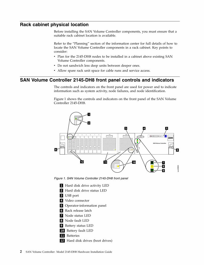
SAN Volume Controller 2145-DH8 front panel controls and indicatorsThe controls and indicators on the front panel are used for power and to indicateinformation such as system activity, node failures, and node identification.
Figure 1 shows the controls and indicators on the front panel of the SAN VolumeController 2145-DH8.
▌1▐ Hard disk drive activity LED▌2▐ Hard disk drive status LED▌3▐ USB port▌4▐ Video connector▌5▐ Operator-information panel▌6▐ Rack release latch▌7▐ Node status LED▌8▐ Node fault LED▌9▐ Battery status LED▌10▐ Battery fault LED▌11▐ Batteries▌12▐ Hard disk drives (boot drives)
SAN Volume Controller
1 3 4 5 6 7 8
aaaa
aaaa
aaaa
aaaa
aaaa
aaaa
aaaa
aaaa
aaaa
aaaa
aaaa
aaaa
aaaa
aaaa
aaaa
aaaa
aaaa
aaaa
aaaa
aaaa
aaaa
aaaa
aaaa
aaaa
aaaa
aaaa
aaaa
aaaa
aaaa
aaaa
aaaa
aaaa
aaaa
aaaa
aaaa
aaaa
aaaa
aaaa
aaaa
aaaa
aaaa
aaaa
aaaa
aaaa
aaaa
aaaa
aaaa
aaaa
aaaa
aaaa
aaaa
aaaa
aaaa
aaaa
aaaa
aaaa
aaaa
aaaa
aaaa
aaaa
aaaa
aaaa
aaaa
aaaa
aaaa
aaaa
aaaa
aaaa
aaaa
aaaa
aaaa
aaaa
aaaa
aaaa
aaaa
aaaa
aaaa
aaaa
aaaa
aaaa
aaaa
aaaa
aaaa
aaaa
aaaa
aaaa
aaaa
aaaa
aaaa
aaaa
aaaa
aaaa
aaaa
aaaa
aaaa
aaaa
aaaa
aaaa
aaaa
aaaa
aaaa
aaaa
aaaa
aaaa
aaaa
aaaa
aaaa
aaaa
aaaa
aaaa
aaaa
aaaa
aaaa
aaaa
aaaa
aaaa
aaaa
aaaa
aaaa
aaaa
aaaa
aaaa
aaaa
aaaa
aaaa
aaaa
+ -2
aaaaaaaaaaaaaaaaaaaaa
aaaaaaaaaaaaaaaaaaaaa
aaaaaaaaaaaaaaaaaaaaa
aaaaaaaaaaaaaaaaaaaaa
aaaaaaaaaaaaaaaaaaaaa
aaaaaaaaaaaaaaaaaaaaa
aaaaaaaaaaaaaaaaaaaaa
aaaaaaaaaaaaaaaaaaaaa
aaaaaaaaaaaaaaaaaaaaa
aaaaaaaaaaaaaaaaaaaaa
aaaaaaaaaaaaaaaaaaaaa
aaaaaaaaaaaaaaaaaaaaa
aaaaaaaaaaaaaaaaaaaaa
aaaaaaaaaaaaaaaaaaaaa
aaaaaaaaaaaaaaaaaaaaa
aaaaaaaaaaaaaaaaaaaaa
aaaaaaaaaaaaaaaaaaaaa
aaaaaaaaaaaaaaaaaaaaa
aaaaaaaaaaaaaaaaaaaaa
aaaaaaaaaaaaaaaaaaaaa
aaaaaaaaaaaaaaaaaaaaa
aaaaaaaaaaaaaaaaaaaaa
aaaaaaaaaaaaaaaaaaaaa
aaaaaaaaaaaaaaaaaaaaa
aaaaaaaaaaaaaaaaaaaaa
aaaaaaaaaaaaaaaaaaaaa
aaaaaaaaaaaaaaaaaaaaa
aaaaaaaaaaaaaaaaaaaaa
aaaaaaaaaaaaaaaaaaaaa
aaaaaaaaaaaaaaaaaaaaa
aaaaaaaaaaaaaaaaaaaaa
aaaaaaaaaaaaaaaaaaaaa
aaaaaaaaaaaaaaaaaaaaa
aaaaaaaaaaaaaaaaaaaaa
+ -1
1 2 3 4
2
4 5
1
2
aaaaaaaaaaaaaaaaaaaaaaaaaaaaaaaaaaaaaaaaaaaaa
aaaaaaaaaaaaaaaaaaaaaaaaaaaaaaaaaaaaaaaaaaaaa
aaaaaaaaaaaaaaaaaaaaaaaaaaaaaaaaaaaaaaaaaaaaa
aaaaaaaaaaaaaaaaaaaaaaaaaaaaaaaaaaaaaaaaaaaaa
aaaaaaaaaaaaaaaaaaaaaaaaaaaaaaaaaaaaaaaaaaaaa
aaaaaaaaaaaaaaaaaaaaaaaaaaaaaaaaaaaaaaaaaaaaa
aaaaaaaaaaaaaaaaaaaaaaaaaaaaaaaaaaaaaaaaaaaaa
aaaaaaaaaaaaaaaaaaaaaaaaaaaaaaaaaaaaaaaaaaaaa
aaaaaaaaaaaaaaaaaaaaaaaaaaaaaaaaaaaaaaaaaaaaa
aaaaaaaaaaaaaaaaaaaaaaaaaaaaaaaaaaaaaaaaaaaaa
aaaaaaaaaaaaaaaaaaaaaaaaaaaaaaaaaaaaaaaaaaaaa
aaaaaaaaaaaaaaaaaaaaaaaaaaaaaaaaaaaaaaaaaaaaa
aaaaaaaaaaaaaaaaaaaaaaaaaaaaaaaaaaaaaaaaaaaaa
aaaaaaaaaaaaaaaaaaaaaaaaaaaaaaaaaaaaaaaaaaaaa
aaaaaaaaaaaaaaaaaaaaaaaaaaaaaaaaaaaaaaaaaaaaa
aaaaaaaaaaaaaaaaaaaaaaaaaaaaaaaaaaaaaaaaaaaaa
aaaaaaaaaaaaaaaaaaaaaaaaaaaaaaaaaaaaaaaaaaaaa
aaaaaaaaaaaaaaaaaaaaaaaaaaaaaaaaaaaaaaaaaaaaa
aaaaaaaaaaaaaaaaaaaaaaaaaaaaaaaaaaaaaaaaaaaaa
aaaaaaaaaaaaaaaaaaaaaaaaaaaaaaaaaaaaaaaaaaaaa
aaaaaaaaaaaaaaaaaaaaaaaaaaaaaaaaaaaaaaaaaaaaa
aaaaaaaaaaaaaaaaaaaaaaaaaaaaaaaaaaaaaaaaaaaaa
aaaaaaaaaaaaaaaaaaaaaaaaaaaaaaaaaaaaaaaaaaaaa
aaaaaaaaaaaaaaaaaaaaaaaaaaaaaaaaaaaaaaaaaaaaa
aaaaaaaaaaaaaaaaaaaaaaaaaaaaaaaaaaaaaaaaaaaaa
aaaaaaaaaaaaaaaaaaaaaaaaaaaaaaaaaaaaaaaaaaaaa
aaaaaaaaaaaaaaaaaaaaaaaaaaaaaaaaaaaaaaaaaaaaa
aaaaaaaaaaaaaaaaaaaaaaaaaaaaaaaaaaaaaaaaaaaaa
aaaaaaaaaaaaaaaaaaaaaaaaaaaaaaaaaaaaaaaaaaaaa
aaaaaaaaaaaaaaaaaaaaaaaaaaaaaaaaaaaaaaaaaaaaa
aaaaaaaaaaaaaaaaaaaaaaaaaaaaaaaaaaaaaaaaaaaaa
aaaaaaaaaaaaaaaaaaaaaaaaaaaaaaaaaaaaaaaaaaaaa
aaaaaaaaaaaaaaaaaaaaaaaaaaaaaaaaaaaaaaaaaaaaa
aaaaaaaaaaaaaaaaaaaaaaaaaaaaaaaaaaaaaaaaaaaaa
aaaaaaaaaaaaaaaaaaaaaaaaaaaaaaaaaaaaaaaaaaaaa
aaaaaaaaaaaaaaaaaaaaaaaaaaaaaaaaaaaaaaaaaaaaa
aaaaaaaaaaaaaaaaaaaaaaaaaaaaaaaaaaaaaaaaaaaaa
10
3
svc00800
6
12
+--
7
8
9
11
6
Figure 1. SAN Volume Controller 2145-DH8 front panel
2 SAN Volume Controller: Model 2145-DH8 Hardware Installation Guide
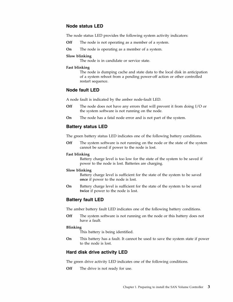
Node status LED
The node status LED provides the following system activity indicators:
Off The node is not operating as a member of a system.
On The node is operating as a member of a system.
Slow blinkingThe node is in candidate or service state.
Fast blinkingThe node is dumping cache and state data to the local disk in anticipationof a system reboot from a pending power-off action or other controlledrestart sequence.
Node fault LED
A node fault is indicated by the amber node-fault LED.
Off The node does not have any errors that will prevent it from doing I/O orthe system software is not running on the node.
On The node has a fatal node error and is not part of the system.
Battery status LED
The green battery status LED indicates one of the following battery conditions.
Off The system software is not running on the node or the state of the systemcannot be saved if power to the node is lost.
Fast blinkingBattery charge level is too low for the state of the system to be saved ifpower to the node is lost. Batteries are charging.
Slow blinkingBattery charge level is sufficient for the state of the system to be savedonce if power to the node is lost.
On Battery charge level is sufficient for the state of the system to be savedtwice if power to the node is lost.
Battery fault LED
The amber battery fault LED indicates one of the following battery conditions.
Off The system software is not running on the node or this battery does nothave a fault.
BlinkingThis battery is being identified.
On This battery has a fault. It cannot be used to save the system state if powerto the node is lost.
Hard disk drive activity LED
The green drive activity LED indicates one of the following conditions.
Off The drive is not ready for use.
Chapter 1. Preparing to install the SAN Volume Controller 3
FlashingThe drive is in use.
On The drive is ready for use, but is not in use.
Hard disk drive status LED
The amber drive status LED indicates one of the following conditions.
Off The drive is in a good state or has no power.
BlinkingThe drive is being identified.
On The drive has failed.
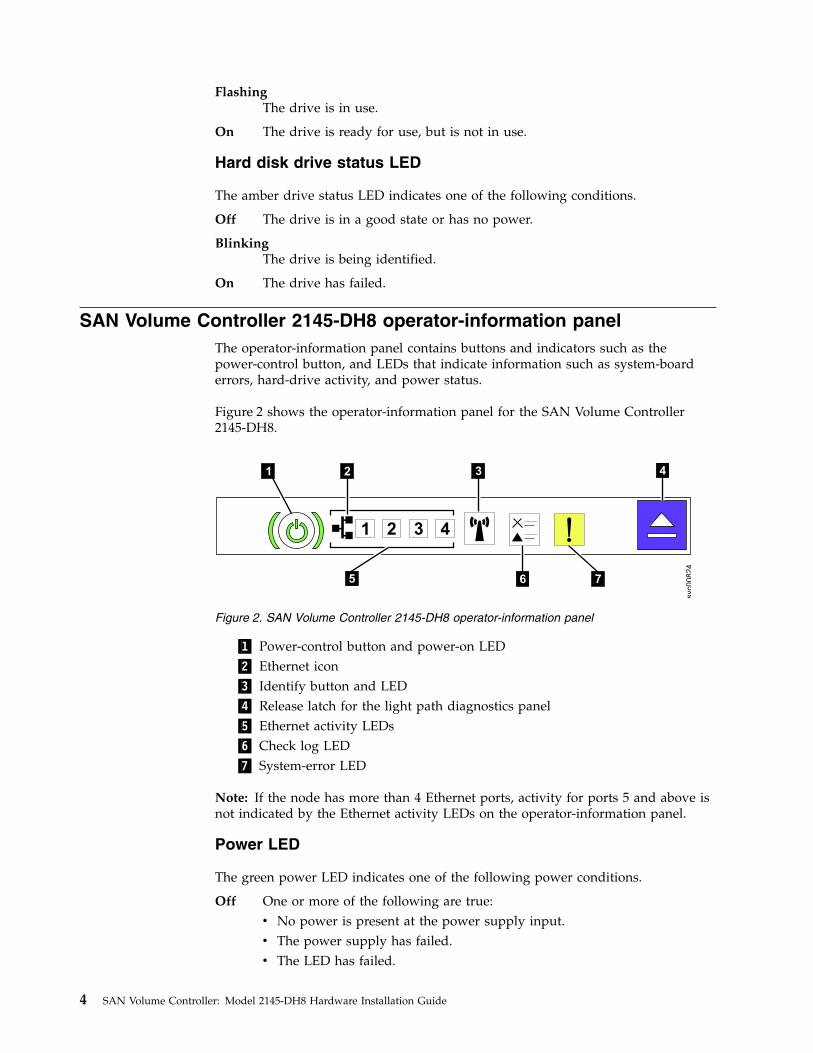
SAN Volume Controller 2145-DH8 operator-information panelThe operator-information panel contains buttons and indicators such as thepower-control button, and LEDs that indicate information such as system-boarderrors, hard-drive activity, and power status.
Figure 2 shows the operator-information panel for the SAN Volume Controller2145-DH8.
▌1▐ Power-control button and power-on LED▌2▐ Ethernet icon▌3▐ Identify button and LED▌4▐ Release latch for the light path diagnostics panel▌5▐ Ethernet activity LEDs▌6▐ Check log LED▌7▐ System-error LED
Note: If the node has more than 4 Ethernet ports, activity for ports 5 and above isnot indicated by the Ethernet activity LEDs on the operator-information panel.
Power LED
The green power LED indicates one of the following power conditions.
Off One or more of the following are true:v No power is present at the power supply input.v The power supply has failed.v The LED has failed.
1 2 3 4
5 6 7
svc00824
1 2 3 4
Figure 2. SAN Volume Controller 2145-DH8 operator-information panel
4 SAN Volume Controller: Model 2145-DH8 Hardware Installation Guide
On The SAN Volume Controller node is turned on.
FlashingThe SAN Volume Controller node is turned off, but is still connected to apower source.
Power button
The power button turns main power on or off for the SAN Volume Controller.v To turn on the power, press and release the power button. You must have a
pointed device, such as a pen, to press the button.v To turn off the power, press and release the power button. For more information
about how to turn off the SAN Volume Controller node, see MAP 5350:Powering off a SAN Volume Controller node.
Attention: When the node is operational and you press and immediately releasethe power button, the SAN Volume Controller writes its control data to its internaldisk and then turns off. This can take up to five minutes. If you press the powerbutton but do not release it, the node turns off immediately without the SANVolume Controller control data being written to disk. Service actions are thenrequired to make the SAN Volume Controller operational again. Therefore, duringa power-off operation, do not press and hold the power button for more than twoseconds.
Ethernet activity LEDs
The Ethernet activity LEDs indicate that the server is transmitting to or receivingsignals on the Ethernet ports. Each LED corresponds to a specific port, andindicates traffic to or from the Ethernet LAN that is connected to that port.
Ethernet activity LED 4 is for activity on the Technician port. Use the ServiceAssistant GUI to see activity on this port.
Identify button and LED
Press the identify button to make the LED blink. The identify LED on the back ofthe 2145-DH8 also blinks.
In the management GUI, select Monitoring > System. Right-click the node andselect Identify. The Identify LED turns on.
System error LED
The amber system-error LED indicates that a system-board error has occurred. Itlights up if the hardware detects a fatal error that requires a new field-replaceableunit (FRU).
Note: See MAP 5800: Light path to help you isolate the faulty FRU.
System information LED
The system-information LED indicates that a noncritical event has occurred. Checkthe light path diagnostics panel and the event log. Light path diagnostics aredescribed in more detail in the light path maintenance analysis procedure (MAP).
Chapter 1. Preparing to install the SAN Volume Controller 5
Release latch
The release latch gives you access to the light-path diagnostics panel, which youcan use to determine the location of a problem.
After pressing the release latch on the operator-information panel, you can slidethe light-path diagnostics panel out to view the LEDs. The LEDs indicate the typeof error that has occurred. See “MAP 5800: Light path” for more detail.
To retract the panel, push it back into the node and snap it into place.
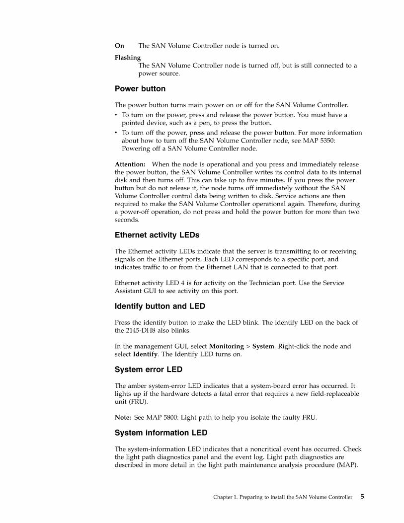
SAN Volume Controller 2145-DH8 rear-panel indicatorsThe rear-panel indicators consist of LEDs that indicate the status of the FibreChannel ports, Ethernet connection and activity, power, electrical current, andsystem-board errors.
Figure 3 shows the rear-panel indicators on the SAN Volume Controller 2145-DH8back-panel assembly.
▌1▐ Ethernet-link LED▌2▐ Ethernet-activity LED▌3▐ Power, location, and system-error LEDs▌4▐ AC, DC, and power-supply error LEDs
Fibre Channel LEDsThe Fibre Channel LEDs indicate the status of the Fibre Channel ports on the SANVolume Controller 2145-DH8 node.
The SAN Volume Controller 2145-DH8 uses two light-emitting diodes (LEDs) perFibre Channel port, which are arranged one above the other. The LEDs arearranged in the same order as the ports. Figure 4 on page 7 shows the location ofthe LEDs.
1
2
3
4
5
6
svc00862
31 42
Figure 3. SAN Volume Controller 2145-DH8 rear-panel indicators
6 SAN Volume Controller: Model 2145-DH8 Hardware Installation Guide
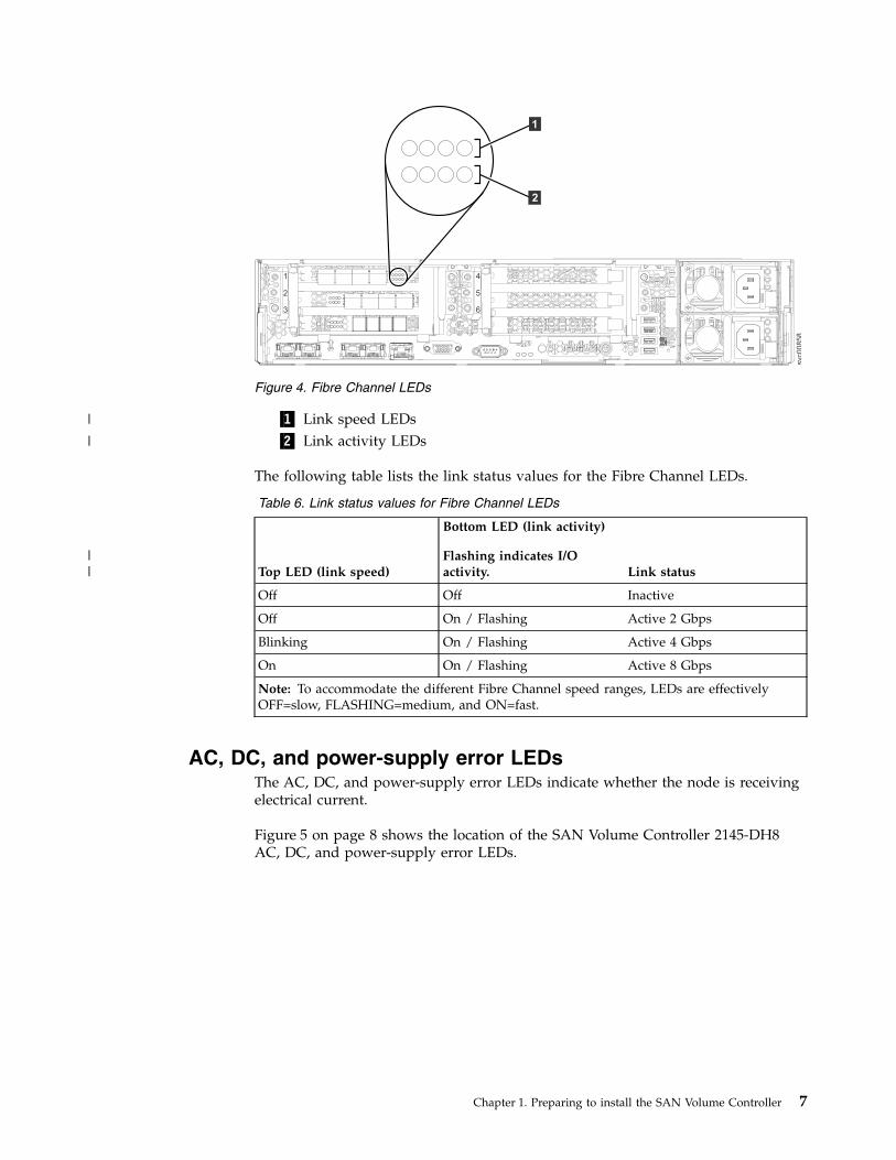
▌1▐ Link speed LEDs▌2▐ Link activity LEDs
The following table lists the link status values for the Fibre Channel LEDs.
Table 6. Link status values for Fibre Channel LEDs
Top LED (link speed)
Bottom LED (link activity)
Flashing indicates I/Oactivity. Link status
Off Off Inactive
Off On / Flashing Active 2 Gbps
Blinking On / Flashing Active 4 Gbps
On On / Flashing Active 8 Gbps
Note: To accommodate the different Fibre Channel speed ranges, LEDs are effectivelyOFF=slow, FLASHING=medium, and ON=fast.
AC, DC, and power-supply error LEDsThe AC, DC, and power-supply error LEDs indicate whether the node is receivingelectrical current.
Figure 5 on page 8 shows the location of the SAN Volume Controller 2145-DH8AC, DC, and power-supply error LEDs.
1
2
3
4
5
6
svc0
08
58
1
2
Figure 4. Fibre Channel LEDs
Chapter 1. Preparing to install the SAN Volume Controller 7
|
|
||
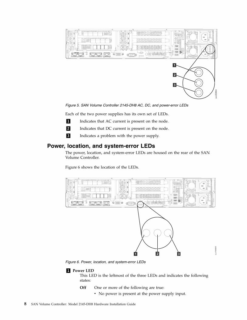
Each of the two power supplies has its own set of LEDs.
▌1▐ Indicates that AC current is present on the node.
▌2▐ Indicates that DC current is present on the node.
▌3▐ Indicates a problem with the power supply.
Power, location, and system-error LEDsThe power, location, and system-error LEDs are housed on the rear of the SANVolume Controller.
Figure 6 shows the location of the LEDs.
▌1▐ Power LEDThis LED is the leftmost of the three LEDs and indicates the followingstates:
Off One or more of the following are true:v No power is present at the power supply input.
1
2
3
4
5
6
svc0
08
64
3
1
2
Figure 5. SAN Volume Controller 2145-DH8 AC, DC, and power-error LEDs
1
2
3
4
5
6
svc00865
321
Figure 6. Power, location, and system-error LEDs
8 SAN Volume Controller: Model 2145-DH8 Hardware Installation Guide
v The power supply has failed.v The LED has failed.
On The SAN Volume Controller is on.
FlashingThe SAN Volume Controller is turned off but is still connected to apower source.
▌2▐ Location LEDThis LED is used to visually locate SAN Volume Controller 2145-DH8nodes from other nodes on the system. This LED is the same as thesystem-locator LED on the front of the node.
▌3▐ System-error LEDThis LED is the rightmost of the three LEDs. The LED indicates that asystem board error has occurred. Light path diagnostics provide moreinformation about the error.
SAN Volume Controller 2145-DH8 Ethernet port LEDsEthernet link and activity LEDs indicate the status of each Ethernet port.v An Ethernet-link LED indicates that the node is communicating on the network
that is connected to the port.v An Ethernet-activity LED indicates an active connection on the port.
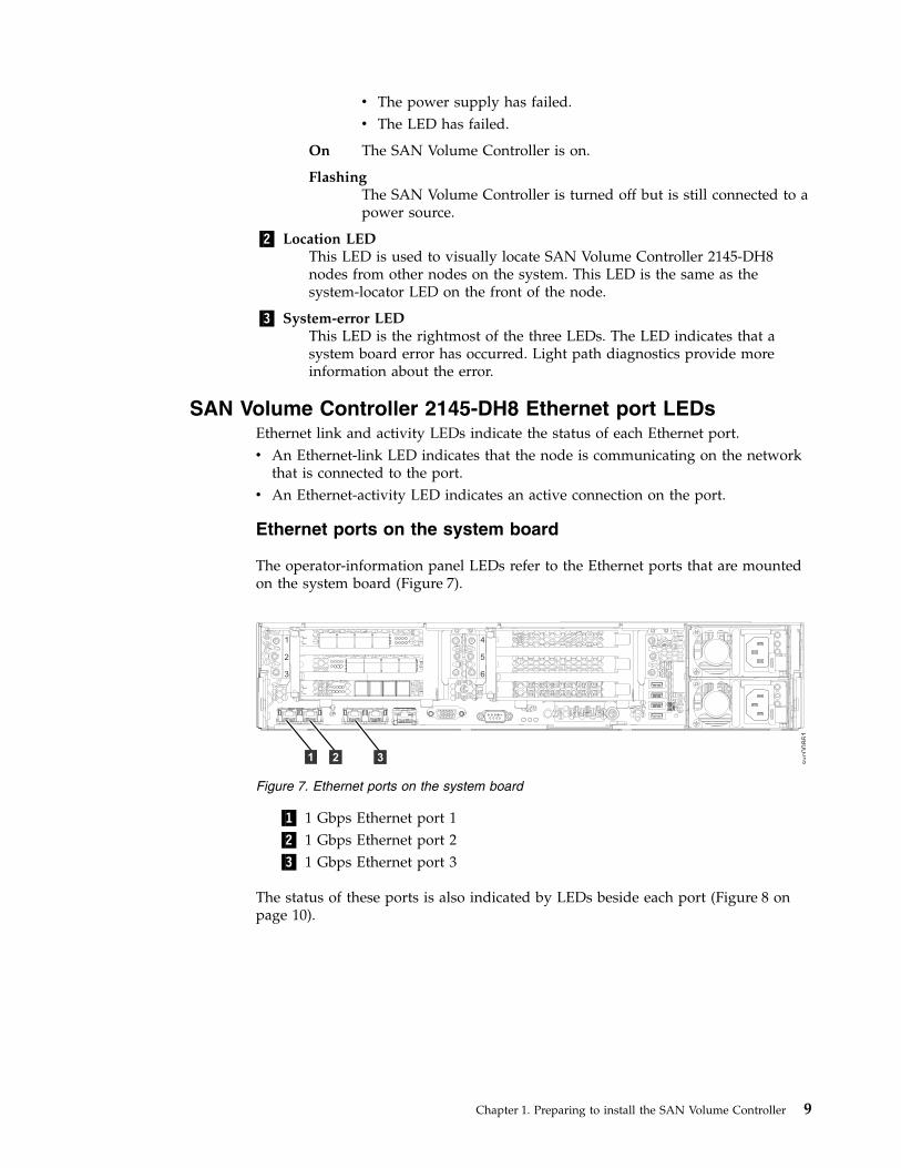
Ethernet ports on the system board
The operator-information panel LEDs refer to the Ethernet ports that are mountedon the system board (Figure 7).
▌1▐ 1 Gbps Ethernet port 1▌2▐ 1 Gbps Ethernet port 2▌3▐ 1 Gbps Ethernet port 3
The status of these ports is also indicated by LEDs beside each port (Figure 8 onpage 10).
1
2
3
4
5
6
svc00861
31 2
Figure 7. Ethernet ports on the system board
Chapter 1. Preparing to install the SAN Volume Controller 9
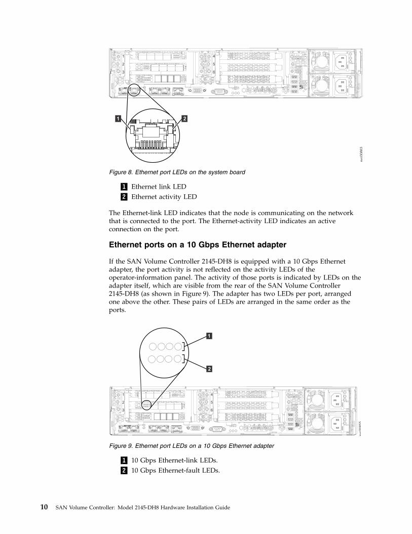
▌1▐ Ethernet link LED▌2▐ Ethernet activity LED
The Ethernet-link LED indicates that the node is communicating on the networkthat is connected to the port. The Ethernet-activity LED indicates an activeconnection on the port.
Ethernet ports on a 10 Gbps Ethernet adapter
If the SAN Volume Controller 2145-DH8 is equipped with a 10 Gbps Ethernetadapter, the port activity is not reflected on the activity LEDs of theoperator-information panel. The activity of those ports is indicated by LEDs on theadapter itself, which are visible from the rear of the SAN Volume Controller2145-DH8 (as shown in Figure 9). The adapter has two LEDs per port, arrangedone above the other. These pairs of LEDs are arranged in the same order as theports.
▌1▐ 10 Gbps Ethernet-link LEDs.▌2▐ 10 Gbps Ethernet-fault LEDs.
1
2
3
4
5
6
svc0
08
63
1 2
Figure 8. Ethernet port LEDs on the system board
1
2
3
4
5
6
svc0
08
55
11
2
Figure 9. Ethernet port LEDs on a 10 Gbps Ethernet adapter
10 SAN Volume Controller: Model 2145-DH8 Hardware Installation Guide
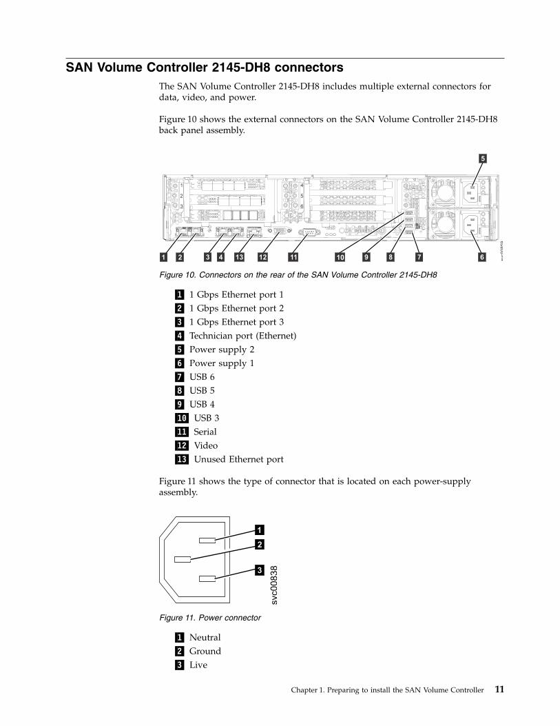
SAN Volume Controller 2145-DH8 connectorsThe SAN Volume Controller 2145-DH8 includes multiple external connectors fordata, video, and power.
Figure 10 shows the external connectors on the SAN Volume Controller 2145-DH8back panel assembly.
▌1▐ 1 Gbps Ethernet port 1▌2▐ 1 Gbps Ethernet port 2▌3▐ 1 Gbps Ethernet port 3▌4▐ Technician port (Ethernet)▌5▐ Power supply 2▌6▐ Power supply 1▌7▐ USB 6▌8▐ USB 5▌9▐ USB 4▌10▐ USB 3▌11▐ Serial▌12▐ Video▌13▐ Unused Ethernet port
Figure 11 shows the type of connector that is located on each power-supplyassembly.
▌1▐ Neutral▌2▐ Ground▌3▐ Live
1
2
3
4
5
6
svc0
08
59
1 11122 3 4 678910
5
13
Figure 10. Connectors on the rear of the SAN Volume Controller 2145-DH8
3
1
2
svc00838
Figure 11. Power connector
Chapter 1. Preparing to install the SAN Volume Controller 11
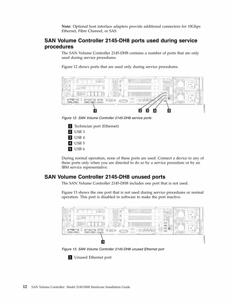
Note: Optional host interface adapters provide additional connectors for 10GbpsEthernet, Fibre Channel, or SAS.
SAN Volume Controller 2145-DH8 ports used during serviceprocedures
The SAN Volume Controller 2145-DH8 contains a number of ports that are onlyused during service procedures.
Figure 12 shows ports that are used only during service procedures.
▌1▐ Technician port (Ethernet)▌2▐ USB 3▌3▐ USB 4▌4▐ USB 5▌5▐ USB 6
During normal operation, none of these ports are used. Connect a device to any ofthese ports only when you are directed to do so by a service procedure or by anIBM service representative.
SAN Volume Controller 2145-DH8 unused portsThe SAN Volume Controller 2145-DH8 includes one port that is not used.
Figure 13 shows the one port that is not used during service procedures or normaloperation. This port is disabled in software to make the port inactive.
▌1▐ Unused Ethernet port
svc00866
1
2
3
4
5
6
52 3 41
Figure 12. SAN Volume Controller 2145-DH8 service ports
1
2
3
4
5
6
svc00867
1
Figure 13. SAN Volume Controller 2145-DH8 unused Ethernet port
12 SAN Volume Controller: Model 2145-DH8 Hardware Installation Guide
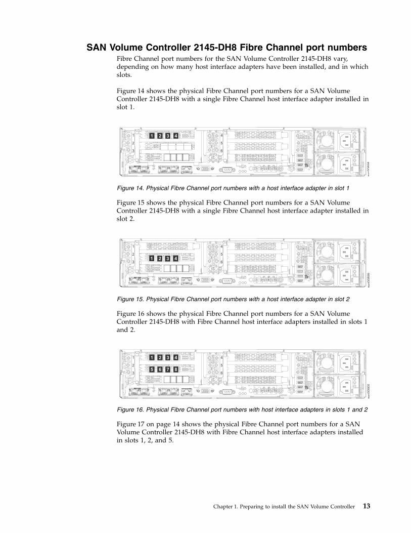
SAN Volume Controller 2145-DH8 Fibre Channel port numbersFibre Channel port numbers for the SAN Volume Controller 2145-DH8 vary,depending on how many host interface adapters have been installed, and in whichslots.
Figure 14 shows the physical Fibre Channel port numbers for a SAN VolumeController 2145-DH8 with a single Fibre Channel host interface adapter installed inslot 1.
Figure 15 shows the physical Fibre Channel port numbers for a SAN VolumeController 2145-DH8 with a single Fibre Channel host interface adapter installed inslot 2.
Figure 16 shows the physical Fibre Channel port numbers for a SAN VolumeController 2145-DH8 with Fibre Channel host interface adapters installed in slots 1and 2.
Figure 17 on page 14 shows the physical Fibre Channel port numbers for a SANVolume Controller 2145-DH8 with Fibre Channel host interface adapters installedin slots 1, 2, and 5.
svc0
08
98
1
2
3
4
5
6
2 3 41
Figure 14. Physical Fibre Channel port numbers with a host interface adapter in slot 1
svc0
08
99
1
2
3
4
5
62 3 41
Figure 15. Physical Fibre Channel port numbers with a host interface adapter in slot 2
svc0
09
00
1
2
3
4
5
66 7 85
2 3 41
Figure 16. Physical Fibre Channel port numbers with host interface adapters in slots 1 and 2
Chapter 1. Preparing to install the SAN Volume Controller 13
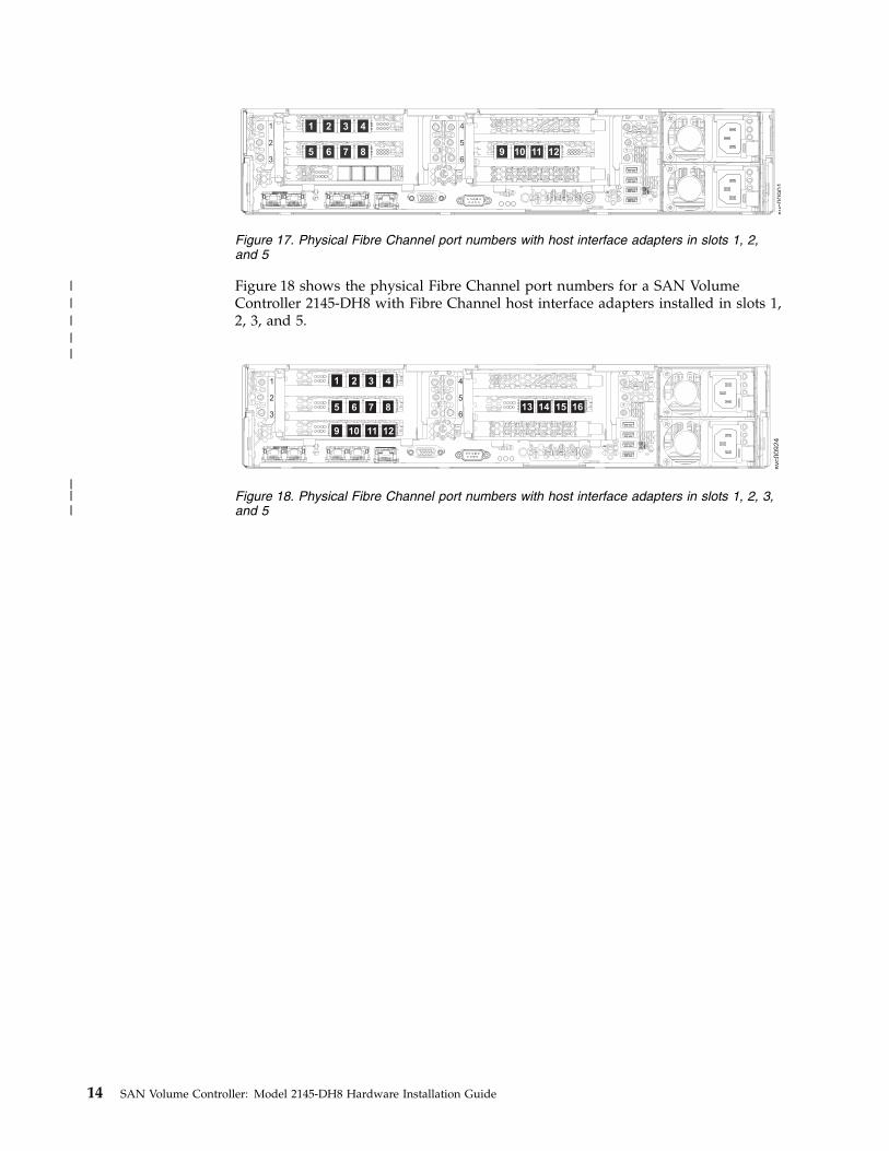
Figure 18 shows the physical Fibre Channel port numbers for a SAN VolumeController 2145-DH8 with Fibre Channel host interface adapters installed in slots 1,2, 3, and 5.
svc0
09
01
1
2
3
4
5
66 7 85 109 11 12
2 3 41
Figure 17. Physical Fibre Channel port numbers with host interface adapters in slots 1, 2,and 5
2 3 411
2
3
4
5
66 7 85
109 1211
13 14 15 16
svc0
09
24
Figure 18. Physical Fibre Channel port numbers with host interface adapters in slots 1, 2, 3,and 5
14 SAN Volume Controller: Model 2145-DH8 Hardware Installation Guide
|
|||
||||
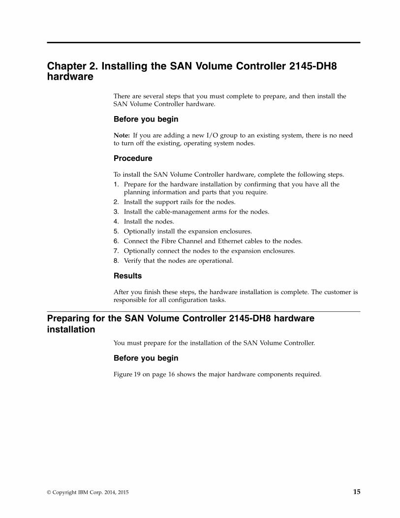
Chapter 2. Installing the SAN Volume Controller 2145-DH8hardware
There are several steps that you must complete to prepare, and then install theSAN Volume Controller hardware.
Before you begin
Note: If you are adding a new I/O group to an existing system, there is no needto turn off the existing, operating system nodes.
Procedure
To install the SAN Volume Controller hardware, complete the following steps.1. Prepare for the hardware installation by confirming that you have all the
planning information and parts that you require.2. Install the support rails for the nodes.3. Install the cable-management arms for the nodes.4. Install the nodes.5. Optionally install the expansion enclosures.6. Connect the Fibre Channel and Ethernet cables to the nodes.7. Optionally connect the nodes to the expansion enclosures.8. Verify that the nodes are operational.
Results
After you finish these steps, the hardware installation is complete. The customer isresponsible for all configuration tasks.
Preparing for the SAN Volume Controller 2145-DH8 hardwareinstallation
You must prepare for the installation of the SAN Volume Controller.
Before you begin
Figure 19 on page 16 shows the major hardware components required.
© Copyright IBM Corp. 2014, 2015 15
▌1▐ SAN Volume Controller 2145-DH8 node▌2▐ SAN Volume Controller 2145-DH8 support rails▌3▐ SAN Volume Controller 2145-DH8 cable-management support bar▌4▐ SAN Volume Controller 2145-DH8 cable-management arm assembly▌5▐ SAN Volume Controller 2145-DH8 cable-management stop bracket
Country-specific power cables come with the SAN Volume Controller node. Thesecables are intended for your country-specific power sockets.
Before you start the installation, verify that all the parts that were ordered havebeen received and that all the optional features are fitted. Verify that you know thequantity of nodes and optional features that were ordered.
2
1
3
4
5
svc0
08
34
Figure 19. Parts provided for SAN Volume Controller 2145-DH8 hardware installation in arack
16 SAN Volume Controller: Model 2145-DH8 Hardware Installation Guide
A label on the main box indicates the features that were shipped.
Note: You must install at least two SAN Volume Controller nodes.
Procedure
To prepare for installation, complete the following steps.1. Ensure that you have everything you need for installation, including the
planning tables and charts. You can obtain the planning tables and charts fromwww.ibm.com/storage/support/2145. The planning information providesguidelines for completing the planning tables and charts. These tables includethe location of hardware, cable connection, and configuration data informationthat you need to complete the installation procedures. Go no further with theseinstructions until you are satisfied that all the information is correct and valid.
2. The label on the main box indicates features that were shipped. Make sure thatthe contents and quantity match the order. The following feature codes areincluded:v Each of the following:
– Feature code 3001: initial SAN Volume Controller 2145-DH8 node,quantity 1
– Feature code 3002: additional SAN Volume Controller 2145-DH8 node,quantity 1
v Optional features as listed in “Optional features”.v One of the following country-specific SAN Volume Controller 2145-DH8
power cable feature codes: 9716, 9717, 9718, 9719, 9720, 9721, 9722, 9723,9725, 9726, 9731, 9732, 9733, 9734, 9735, 9736, or 9737.
3. Check that the correct part set has been shipped for the feature codes. Unlessotherwise stated, the feature code contents are in the main box.v Feature codes 3001 and 3002 ship the same parts. Verify that you have the
listed parts:– SAN Volume Controller 2145-DH8 node– Part number 81Y6821: SAN Volume Controller 2145-DH8 Support rail kit,
quantity 1– Part number 69Y1192: SAN Volume Controller 2145-DH8
Cable-management arm assembly, quantity 1– The support rail kit contains a number of components within its box.
Verify that you have the following items:- One left side rail- One right side rail- Four M6 screws
v Feature codes 9716, 9717, 9718, 9719, 9720, 9721, 9722, 9723, 9725, 9726, 9731,9732, 9733, 9734, 9735, 9736, and 9737 each ship a single power cable. Use thepower plug that is appropriate to your location unless you are connecting toa rack-mounted power distribution unit.
v SAN Volume Controller publications: ship group (one box of publications perpair of 2145-DH8 nodes):– SAN Volume Controller Publications CD– SAN Volume Controller Read First
– IBM Systems Safety Notices CD– IBM SAN Volume Controller Model 2145-DH8 Hardware Installation Guide
Chapter 2. Installing the SAN Volume Controller 2145-DH8 hardware 17
– SAN Volume Controller License Information for SAN Volume Controller CD– SAN Volume Controller Statement of Limited Warranty flyer– Environmental Notices CD– IBM license information for machine code– Other miscellaneous flyers
If feature codes 5305, or 5325 are not ordered for Fibre Channel connection, youmust supply your own fiber-optic Fibre Channel cables. Make sure that fourcables per adapter are available.If feature code AH12 is ordered, and feature codes 5305 and 5325 or ACSS arenot ordered for Ethernet connection, the customer must supply their own OM2or OM3 fiber-optic cables. Make sure that four cables per node are available.At least one network adapter feature code AH10, AH11, AH14, or AH12 isfitted in each 2145-DH8.
Note: Part numbers and feature codes are subject to change between SANVolume Controller releases. The numbers listed here might not always reflectwhat you receive.
Installing the SAN Volume Controller 2145-DH8You must complete several tasks to install the SAN Volume Controller 2145-DH8node.
About this task
Installing a SAN Volume Controller 2145-DH8 node consists of the following tasks:1. Installing the support rails in the rack cabinet.2. Installing the node in the rack.3. Installing the cable-management arm in the rack cabinet.
Important: Do not connect the power to the node until the day that you will bepowering it on by pressing the power button. The batteries can become dischargedif the node is connected to power, but not powered on. To prevent this fromhappening, complete the appropriate steps from Table 7.
Table 7. Preventing the batteries from discharging
In this situation . . . Complete the following steps
You connect the power to the node, butmight not power it on by pressing thepower button on the same day.
1. Pull both batteries out of the node. Keepthem out until you're ready to power onthe node. Refer to “Removing the SANVolume Controller 2145-DH8 battery”.
2. Push the batteries in just before youpress the power button to power on thenode. Refer to “Replacing the SANVolume Controller 2145-DH8 battery”.
You power off the node, and might notpower it on the same day.
1. Pull both batteries out of the node. Keepthem out until you're ready to power onthe node.
2. Push the batteries in before you press thepower button to power on the node.
18 SAN Volume Controller: Model 2145-DH8 Hardware Installation Guide
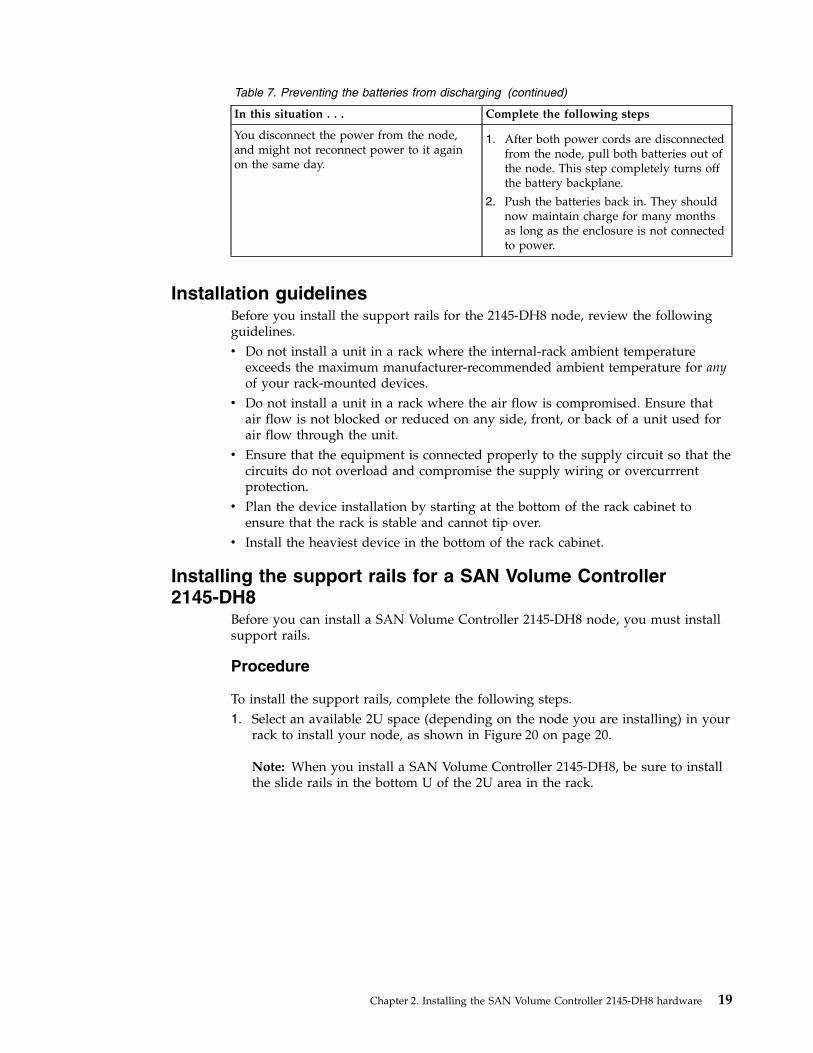
Table 7. Preventing the batteries from discharging (continued)
In this situation . . . Complete the following steps
You disconnect the power from the node,and might not reconnect power to it againon the same day.
1. After both power cords are disconnectedfrom the node, pull both batteries out ofthe node. This step completely turns offthe battery backplane.
2. Push the batteries back in. They shouldnow maintain charge for many monthsas long as the enclosure is not connectedto power.
Installation guidelinesBefore you install the support rails for the 2145-DH8 node, review the followingguidelines.v Do not install a unit in a rack where the internal-rack ambient temperature
exceeds the maximum manufacturer-recommended ambient temperature for anyof your rack-mounted devices.
v Do not install a unit in a rack where the air flow is compromised. Ensure thatair flow is not blocked or reduced on any side, front, or back of a unit used forair flow through the unit.
v Ensure that the equipment is connected properly to the supply circuit so that thecircuits do not overload and compromise the supply wiring or overcurrrentprotection.
v Plan the device installation by starting at the bottom of the rack cabinet toensure that the rack is stable and cannot tip over.
v Install the heaviest device in the bottom of the rack cabinet.
Installing the support rails for a SAN Volume Controller2145-DH8
Before you can install a SAN Volume Controller 2145-DH8 node, you must installsupport rails.
Procedure
To install the support rails, complete the following steps.1. Select an available 2U space (depending on the node you are installing) in your
rack to install your node, as shown in Figure 20 on page 20.
Note: When you install a SAN Volume Controller 2145-DH8, be sure to installthe slide rails in the bottom U of the 2U area in the rack.
Chapter 2. Installing the SAN Volume Controller 2145-DH8 hardware 19
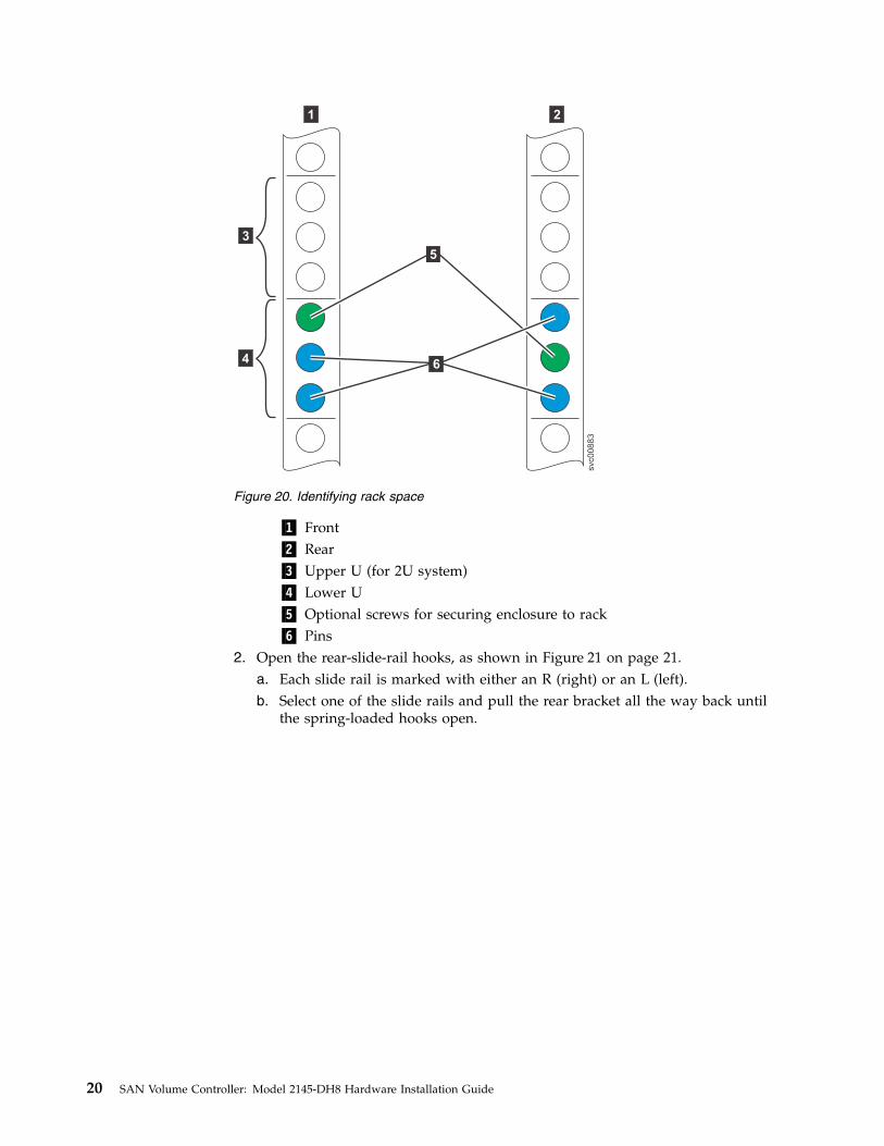
▌1▐ Front▌2▐ Rear▌3▐ Upper U (for 2U system)▌4▐ Lower U▌5▐ Optional screws for securing enclosure to rack▌6▐ Pins
2. Open the rear-slide-rail hooks, as shown in Figure 21 on page 21.a. Each slide rail is marked with either an R (right) or an L (left).b. Select one of the slide rails and pull the rear bracket all the way back until
the spring-loaded hooks open.
svc00883
3
4
1 2
5
6
Figure 20. Identifying rack space
20 SAN Volume Controller: Model 2145-DH8 Hardware Installation Guide
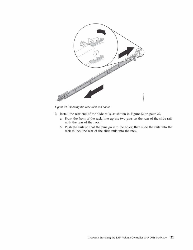
3. Install the rear end of the slide rails, as shown in Figure 22 on page 22.a. From the front of the rack, line up the two pins on the rear of the slide rail
with the rear of the rack.b. Push the rails so that the pins go into the holes; then slide the rails into the
rack to lock the rear of the slide rails into the rack.
svc00878
Figure 21. Opening the rear slide-rail hooks
Chapter 2. Installing the SAN Volume Controller 2145-DH8 hardware 21
▌1▐ Square-hole rack▌2▐ Round-hole rack
4. If they are closed when you receive them, open the latches by pushing the bluebutton ▌1▐ in and pushing the latch ▌2▐ back, as shown in Figure 23 on page23.
Note: If your slide rails are shipped with the front latches in the open position,skip this step and go to step 5 on page 23.
svc00879
1
2
Figure 22. Installing rear end of slide rail
22 SAN Volume Controller: Model 2145-DH8 Hardware Installation Guide
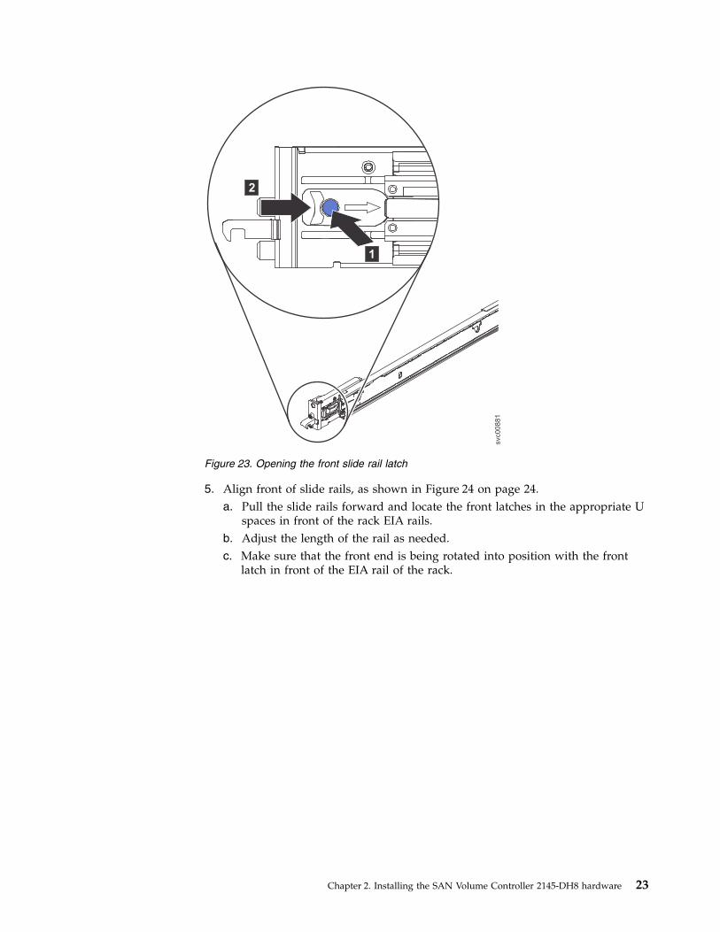
5. Align front of slide rails, as shown in Figure 24 on page 24.a. Pull the slide rails forward and locate the front latches in the appropriate U
spaces in front of the rack EIA rails.b. Adjust the length of the rail as needed.c. Make sure that the front end is being rotated into position with the front
latch in front of the EIA rail of the rack.
1
2
svc00881
Figure 23. Opening the front slide rail latch
Chapter 2. Installing the SAN Volume Controller 2145-DH8 hardware 23
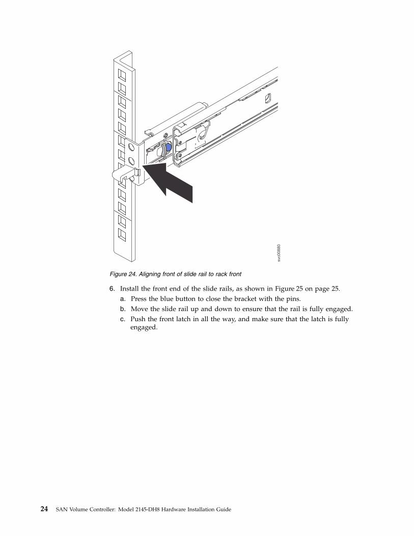
6. Install the front end of the slide rails, as shown in Figure 25 on page 25.a. Press the blue button to close the bracket with the pins.b. Move the slide rail up and down to ensure that the rail is fully engaged.c. Push the front latch in all the way, and make sure that the latch is fully
engaged.
svc00880
Figure 24. Aligning front of slide rail to rack front
24 SAN Volume Controller: Model 2145-DH8 Hardware Installation Guide
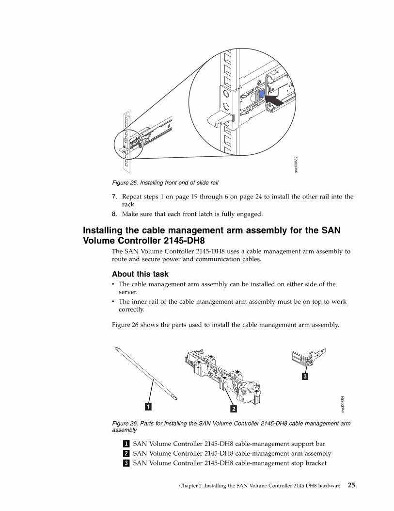
7. Repeat steps 1 on page 19 through 6 on page 24 to install the other rail into therack.
8. Make sure that each front latch is fully engaged.
Installing the cable management arm assembly for the SANVolume Controller 2145-DH8
The SAN Volume Controller 2145-DH8 uses a cable management arm assembly toroute and secure power and communication cables.
About this taskv The cable management arm assembly can be installed on either side of the
server.v The inner rail of the cable management arm assembly must be on top to work
correctly.
Figure 26 shows the parts used to install the cable management arm assembly.
▌1▐ SAN Volume Controller 2145-DH8 cable-management support bar▌2▐ SAN Volume Controller 2145-DH8 cable-management arm assembly▌3▐ SAN Volume Controller 2145-DH8 cable-management stop bracket
svc00882
Figure 25. Installing front end of slide rail
svc00884
21
3
Figure 26. Parts for installing the SAN Volume Controller 2145-DH8 cable management armassembly
Chapter 2. Installing the SAN Volume Controller 2145-DH8 hardware 25
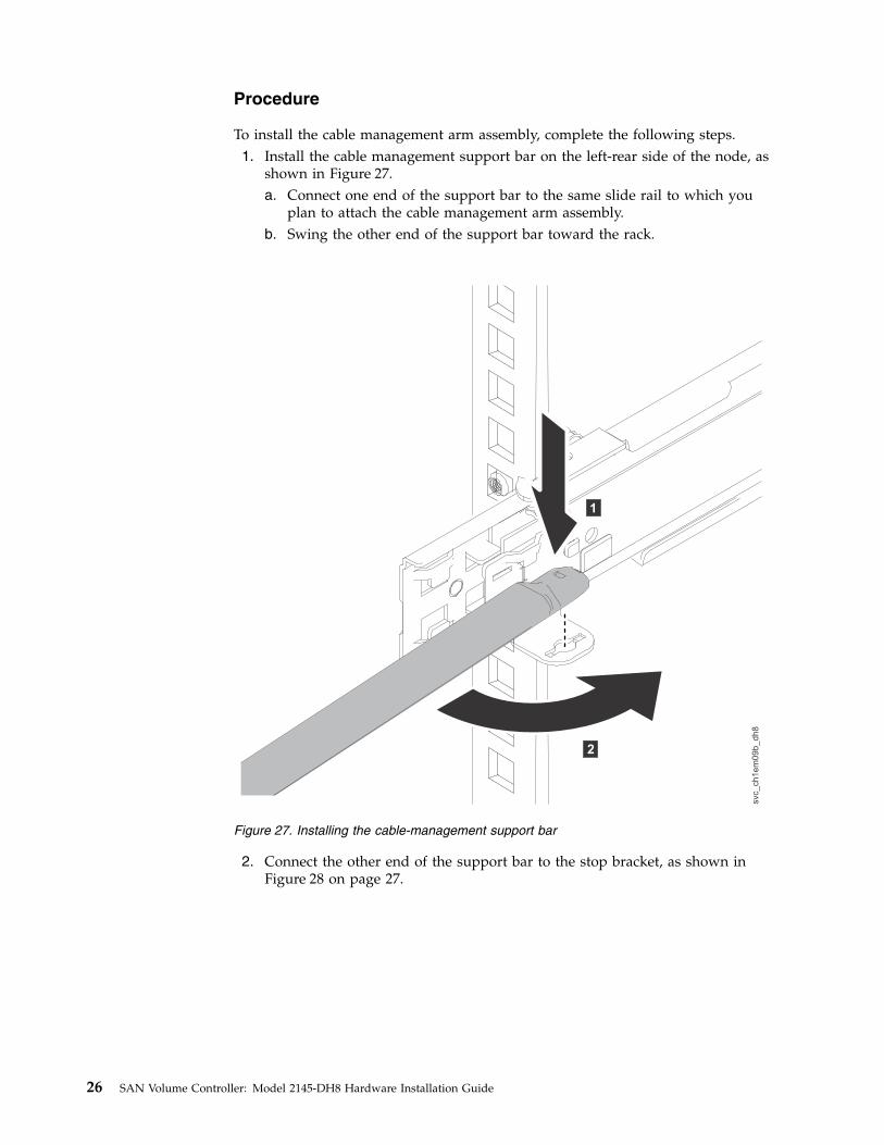
Procedure
To install the cable management arm assembly, complete the following steps.1. Install the cable management support bar on the left-rear side of the node, as
shown in Figure 27.a. Connect one end of the support bar to the same slide rail to which you
plan to attach the cable management arm assembly.b. Swing the other end of the support bar toward the rack.
2. Connect the other end of the support bar to the stop bracket, as shown inFigure 28 on page 27.
Figure 27. Installing the cable-management support bar
26 SAN Volume Controller: Model 2145-DH8 Hardware Installation Guide
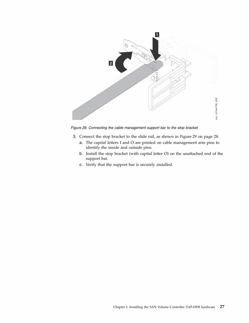
3. Connect the stop bracket to the slide rail, as shown in Figure 29 on page 28.a. The capital letters I and O are printed on cable management arm pins to
identify the inside and outside pins.b. Install the stop bracket (with capital letter O) on the unattached end of the
support bar.c. Verify that the support bar is securely installed.
Figure 28. Connecting the cable management support bar to the stop bracket
Chapter 2. Installing the SAN Volume Controller 2145-DH8 hardware 27
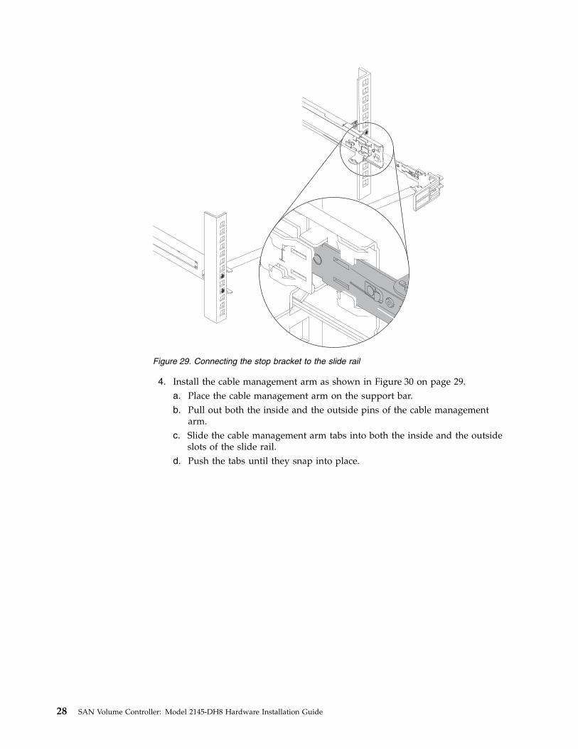
4. Install the cable management arm as shown in Figure 30 on page 29.a. Place the cable management arm on the support bar.b. Pull out both the inside and the outside pins of the cable management
arm.c. Slide the cable management arm tabs into both the inside and the outside
slots of the slide rail.d. Push the tabs until they snap into place.
Figure 29. Connecting the stop bracket to the slide rail
28 SAN Volume Controller: Model 2145-DH8 Hardware Installation Guide
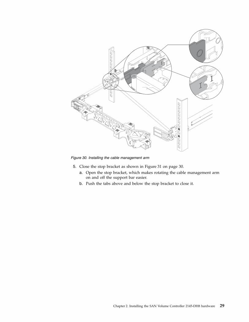
5. Close the stop bracket as shown in Figure 31 on page 30.a. Open the stop bracket, which makes rotating the cable management arm
on and off the support bar easier.b. Push the tabs above and below the stop bracket to close it.
Figure 30. Installing the cable management arm
Chapter 2. Installing the SAN Volume Controller 2145-DH8 hardware 29
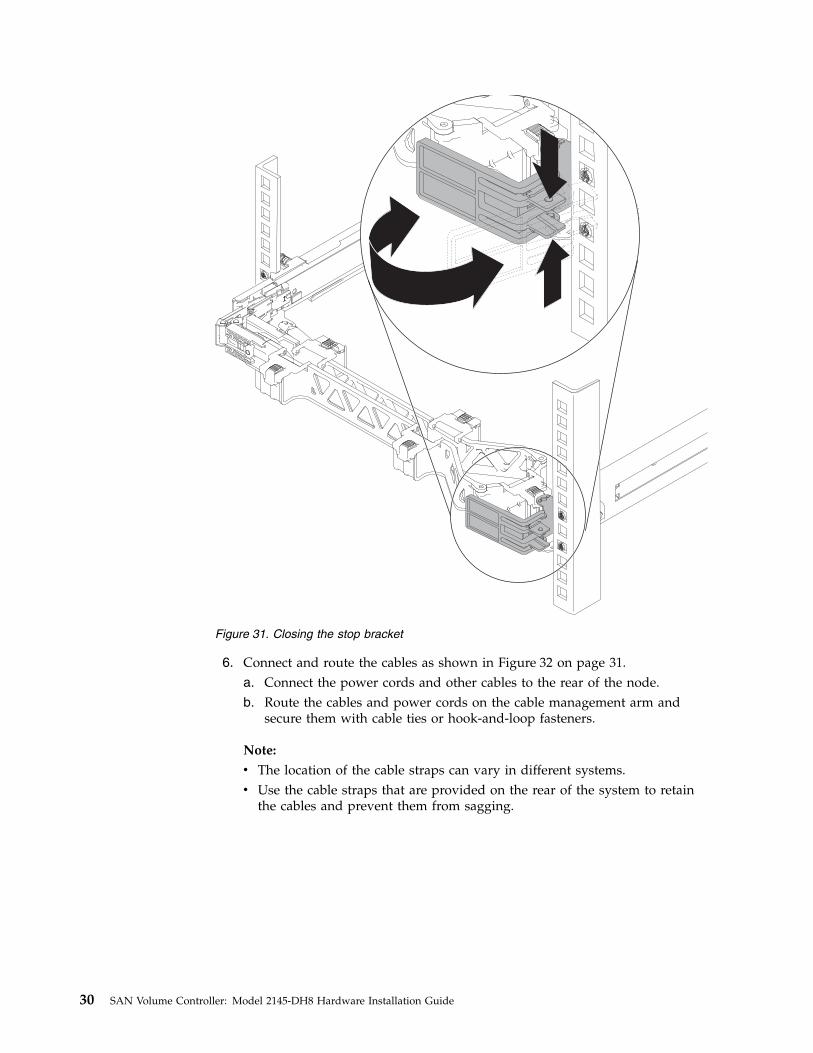
6. Connect and route the cables as shown in Figure 32 on page 31.a. Connect the power cords and other cables to the rear of the node.b. Route the cables and power cords on the cable management arm and
secure them with cable ties or hook-and-loop fasteners.
Note:
v The location of the cable straps can vary in different systems.v Use the cable straps that are provided on the rear of the system to retain
the cables and prevent them from sagging.
Figure 31. Closing the stop bracket
30 SAN Volume Controller: Model 2145-DH8 Hardware Installation Guide
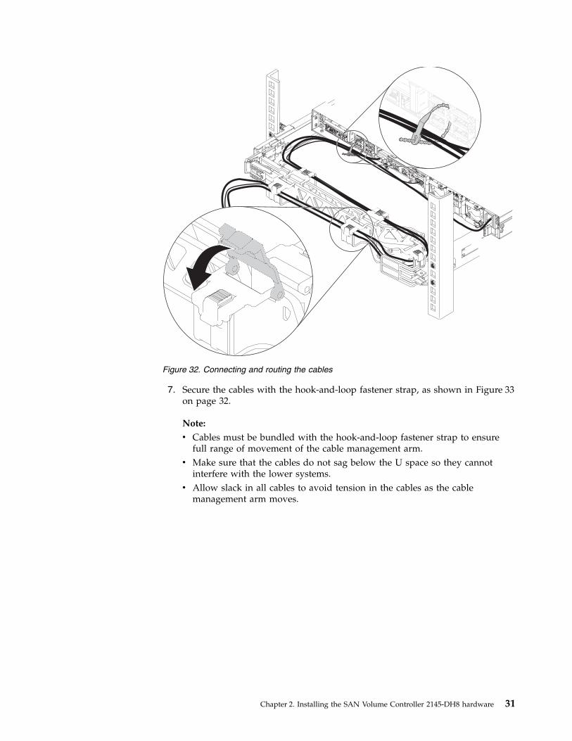
7. Secure the cables with the hook-and-loop fastener strap, as shown in Figure 33on page 32.
Note:
v Cables must be bundled with the hook-and-loop fastener strap to ensurefull range of movement of the cable management arm.
v Make sure that the cables do not sag below the U space so they cannotinterfere with the lower systems.
v Allow slack in all cables to avoid tension in the cables as the cablemanagement arm moves.
Figure 32. Connecting and routing the cables
Chapter 2. Installing the SAN Volume Controller 2145-DH8 hardware 31
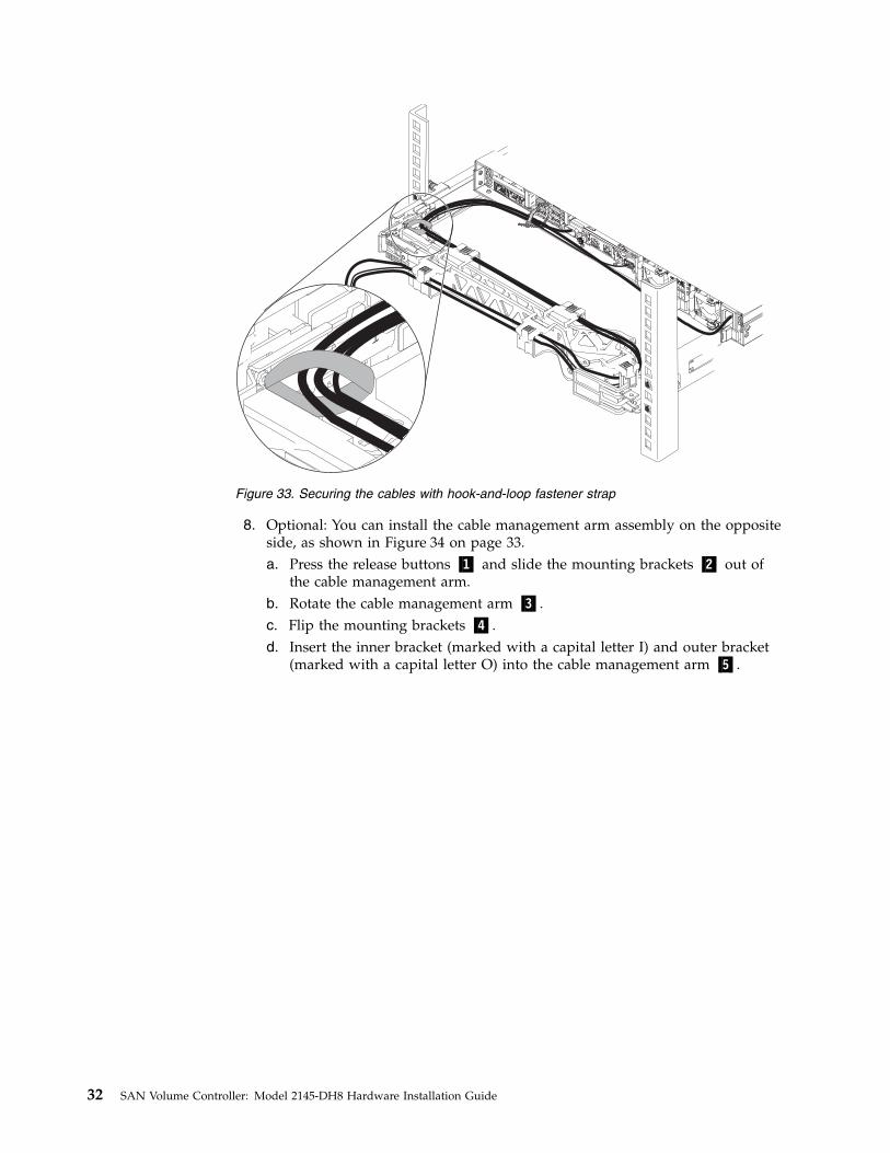
8. Optional: You can install the cable management arm assembly on the oppositeside, as shown in Figure 34 on page 33.a. Press the release buttons ▌1▐ and slide the mounting brackets ▌2▐ out of
the cable management arm.b. Rotate the cable management arm ▌3▐.c. Flip the mounting brackets ▌4▐.d. Insert the inner bracket (marked with a capital letter I) and outer bracket
(marked with a capital letter O) into the cable management arm ▌5▐.
Figure 33. Securing the cables with hook-and-loop fastener strap
32 SAN Volume Controller: Model 2145-DH8 Hardware Installation Guide
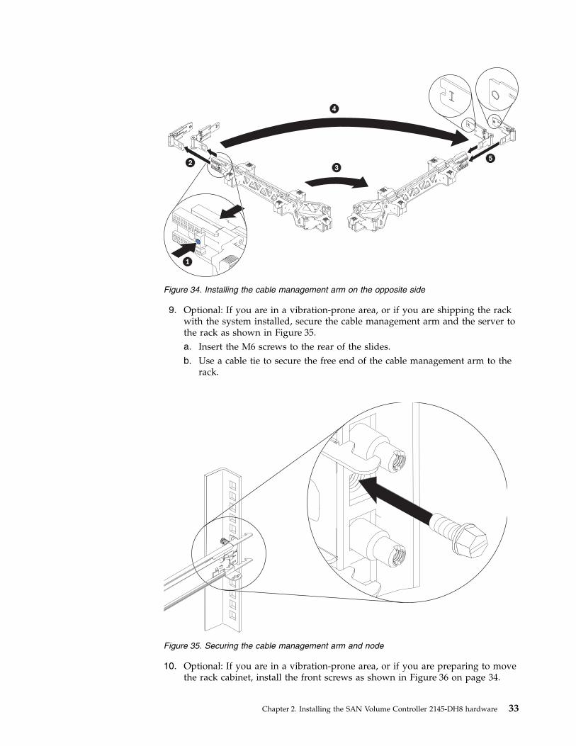
9. Optional: If you are in a vibration-prone area, or if you are shipping the rackwith the system installed, secure the cable management arm and the server tothe rack as shown in Figure 35.a. Insert the M6 screws to the rear of the slides.b. Use a cable tie to secure the free end of the cable management arm to the
rack.
10. Optional: If you are in a vibration-prone area, or if you are preparing to movethe rack cabinet, install the front screws as shown in Figure 36 on page 34.
Figure 34. Installing the cable management arm on the opposite side
Figure 35. Securing the cable management arm and node
Chapter 2. Installing the SAN Volume Controller 2145-DH8 hardware 33
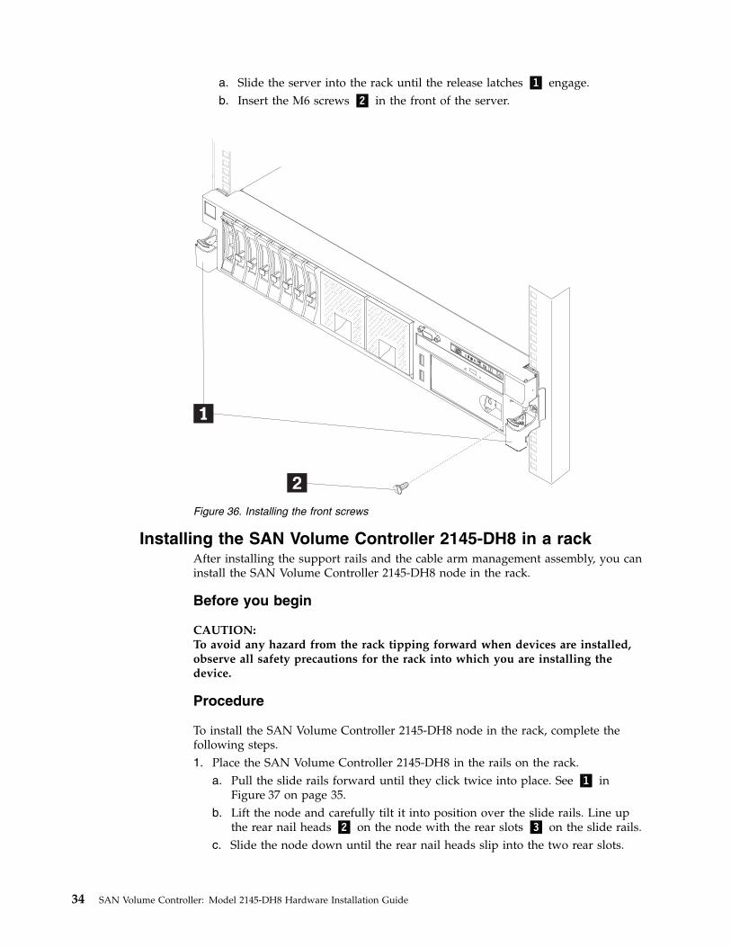
a. Slide the server into the rack until the release latches ▌1▐ engage.b. Insert the M6 screws ▌2▐ in the front of the server.
Installing the SAN Volume Controller 2145-DH8 in a rackAfter installing the support rails and the cable arm management assembly, you caninstall the SAN Volume Controller 2145-DH8 node in the rack.
Before you begin
CAUTION:To avoid any hazard from the rack tipping forward when devices are installed,observe all safety precautions for the rack into which you are installing thedevice.
Procedure
To install the SAN Volume Controller 2145-DH8 node in the rack, complete thefollowing steps.1. Place the SAN Volume Controller 2145-DH8 in the rails on the rack.
a. Pull the slide rails forward until they click twice into place. See ▌1▐ inFigure 37 on page 35.
b. Lift the node and carefully tilt it into position over the slide rails. Line upthe rear nail heads ▌2▐ on the node with the rear slots ▌3▐ on the slide rails.
c. Slide the node down until the rear nail heads slip into the two rear slots.
Figure 36. Installing the front screws
34 SAN Volume Controller: Model 2145-DH8 Hardware Installation Guide
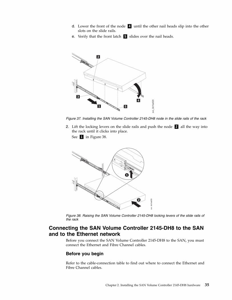
d. Lower the front of the node ▌4▐ until the other nail heads slip into the otherslots on the slide rails.
e. Verify that the front latch ▌5▐ slides over the nail heads.
2. Lift the locking levers on the slide rails and push the node ▌2▐ all the way intothe rack until it clicks into place.See ▌1▐ in Figure 38.
Connecting the SAN Volume Controller 2145-DH8 to the SANand to the Ethernet network
Before you connect the SAN Volume Controller 2145-DH8 to the SAN, you mustconnect the Ethernet and Fibre Channel cables.
Before you begin
Refer to the cable-connection table to find out where to connect the Ethernet andFibre Channel cables.
svc_
bb
1ka
02
0
Figure 37. Installing the SAN Volume Controller 2145-DH8 node in the slide rails of the rack
svc_bb1ka055
Figure 38. Raising the SAN Volume Controller 2145-DH8 locking levers of the slide rails ofthe rack
Chapter 2. Installing the SAN Volume Controller 2145-DH8 hardware 35
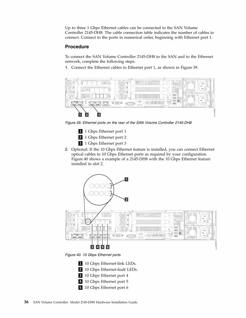
Up to three 1 Gbps Ethernet cables can be connected to the SAN VolumeController 2145-DH8. The cable connection table indicates the number of cables toconnect. Connect to the ports in numerical order, beginning with Ethernet port 1.
Procedure
To connect the SAN Volume Controller 2145-DH8 to the SAN and to the Ethernetnetwork, complete the following steps.1. Connect the Ethernet cables to Ethernet port 1, as shown in Figure 39.
▌1▐ 1 Gbps Ethernet port 1▌2▐ 1 Gbps Ethernet port 2▌3▐ 1 Gbps Ethernet port 3
2. Optional: If the 10 Gbps Ethernet feature is installed, you can connect Ethernetoptical cables to 10 Gbps Ethernet ports as required by your configuration.Figure 40 shows a example of a 2145-DH8 with the 10 Gbps Ethernet featureinstalled in slot 2.
▌1▐ 10 Gbps Ethernet-link LEDs.▌2▐ 10 Gbps Ethernet-fault LEDs.▌3▐ 10 Gbps Ethernet port 4▌4▐ 10 Gbps Ethernet port 5▌5▐ 10 Gbps Ethernet port 6
1
2
3
4
5
6
svc00861
31 2
Figure 39. Ethernet ports on the rear of the SAN Volume Controller 2145-DH8
1
2
3
4
5
6
svc0
08
75
11
2
3 4 5 6
Figure 40. 10 Gbps Ethernet ports
36 SAN Volume Controller: Model 2145-DH8 Hardware Installation Guide
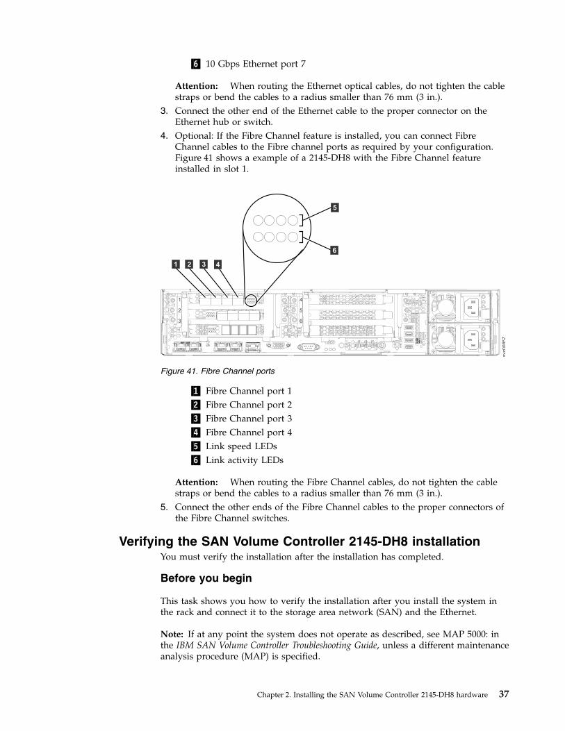
▌6▐ 10 Gbps Ethernet port 7
Attention: When routing the Ethernet optical cables, do not tighten the cablestraps or bend the cables to a radius smaller than 76 mm (3 in.).
3. Connect the other end of the Ethernet cable to the proper connector on theEthernet hub or switch.
4. Optional: If the Fibre Channel feature is installed, you can connect FibreChannel cables to the Fibre channel ports as required by your configuration.Figure 41 shows a example of a 2145-DH8 with the Fibre Channel featureinstalled in slot 1.
▌1▐ Fibre Channel port 1▌2▐ Fibre Channel port 2▌3▐ Fibre Channel port 3▌4▐ Fibre Channel port 4▌5▐ Link speed LEDs▌6▐ Link activity LEDs
Attention: When routing the Fibre Channel cables, do not tighten the cablestraps or bend the cables to a radius smaller than 76 mm (3 in.).
5. Connect the other ends of the Fibre Channel cables to the proper connectors ofthe Fibre Channel switches.
Verifying the SAN Volume Controller 2145-DH8 installationYou must verify the installation after the installation has completed.
Before you begin
This task shows you how to verify the installation after you install the system inthe rack and connect it to the storage area network (SAN) and the Ethernet.
Note: If at any point the system does not operate as described, see MAP 5000: inthe IBM SAN Volume Controller Troubleshooting Guide, unless a different maintenanceanalysis procedure (MAP) is specified.
1
2
3
4
5
6
svc0
08
57
3 41 2
6
5
Figure 41. Fibre Channel ports
Chapter 2. Installing the SAN Volume Controller 2145-DH8 hardware 37
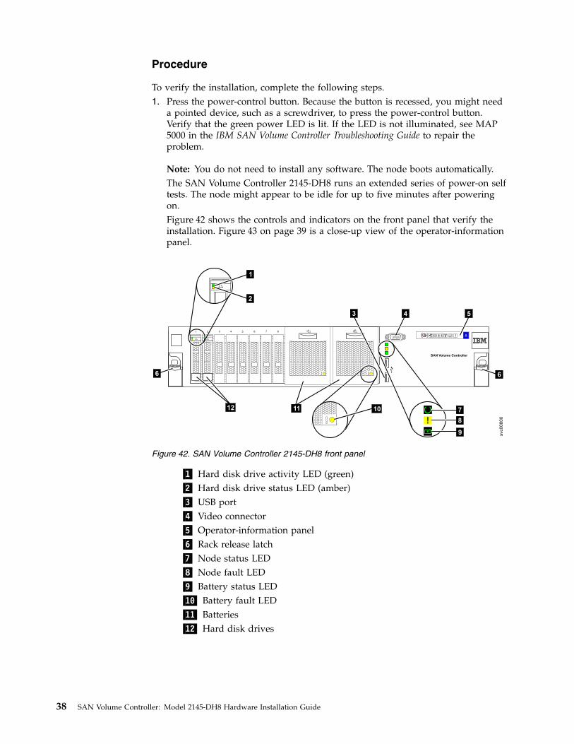
Procedure
To verify the installation, complete the following steps.1. Press the power-control button. Because the button is recessed, you might need
a pointed device, such as a screwdriver, to press the power-control button.Verify that the green power LED is lit. If the LED is not illuminated, see MAP5000 in the IBM SAN Volume Controller Troubleshooting Guide to repair theproblem.
Note: You do not need to install any software. The node boots automatically.The SAN Volume Controller 2145-DH8 runs an extended series of power-on selftests. The node might appear to be idle for up to five minutes after poweringon.Figure 42 shows the controls and indicators on the front panel that verify theinstallation. Figure 43 on page 39 is a close-up view of the operator-informationpanel.
▌1▐ Hard disk drive activity LED (green)▌2▐ Hard disk drive status LED (amber)▌3▐ USB port▌4▐ Video connector▌5▐ Operator-information panel▌6▐ Rack release latch▌7▐ Node status LED▌8▐ Node fault LED▌9▐ Battery status LED▌10▐ Battery fault LED▌11▐ Batteries▌12▐ Hard disk drives
SAN Volume Controller
1 3 4 5 6 7 8
aaaa
aaaa
aaaa
aaaa
aaaa
aaaa
aaaa
aaaa
aaaa
aaaa
aaaa
aaaa
aaaa
aaaa
aaaa
aaaa
aaaa
aaaa
aaaa
aaaa
aaaa
aaaa
aaaa
aaaa
aaaa
aaaa
aaaa
aaaa
aaaa
aaaa
aaaa
aaaa
aaaa
aaaa
aaaa
aaaa
aaaa
aaaa
aaaa
aaaa
aaaa
aaaa
aaaa
aaaa
aaaa
aaaa
aaaa
aaaa
aaaa
aaaa
aaaa
aaaa
aaaa
aaaa
aaaa
aaaa
aaaa
aaaa
aaaa
aaaa
aaaa
aaaa
aaaa
aaaa
aaaa
aaaa
aaaa
aaaa
aaaa
aaaa
aaaa
aaaa
aaaa
aaaa
aaaa
aaaa
aaaa
aaaa
aaaa
aaaa
aaaa
aaaa
aaaa
aaaa
aaaa
aaaa
aaaa
aaaa
aaaa
aaaa
aaaa
aaaa
aaaa
aaaa
aaaa
aaaa
aaaa
aaaa
aaaa
aaaa
aaaa
aaaa
aaaa
aaaa
aaaa
aaaa
aaaa
aaaa
aaaa
aaaa
aaaa
aaaa
aaaa
aaaa
aaaa
aaaa
aaaa
aaaa
aaaa
aaaa
aaaa
aaaa
aaaa
aaaa
aaaa
aaaa
+ -2
aaaaaaaaaaaaaaaaaaaaa
aaaaaaaaaaaaaaaaaaaaa
aaaaaaaaaaaaaaaaaaaaa
aaaaaaaaaaaaaaaaaaaaa
aaaaaaaaaaaaaaaaaaaaa
aaaaaaaaaaaaaaaaaaaaa
aaaaaaaaaaaaaaaaaaaaa
aaaaaaaaaaaaaaaaaaaaa
aaaaaaaaaaaaaaaaaaaaa
aaaaaaaaaaaaaaaaaaaaa
aaaaaaaaaaaaaaaaaaaaa
aaaaaaaaaaaaaaaaaaaaa
aaaaaaaaaaaaaaaaaaaaa
aaaaaaaaaaaaaaaaaaaaa
aaaaaaaaaaaaaaaaaaaaa
aaaaaaaaaaaaaaaaaaaaa
aaaaaaaaaaaaaaaaaaaaa
aaaaaaaaaaaaaaaaaaaaa
aaaaaaaaaaaaaaaaaaaaa
aaaaaaaaaaaaaaaaaaaaa
aaaaaaaaaaaaaaaaaaaaa
aaaaaaaaaaaaaaaaaaaaa
aaaaaaaaaaaaaaaaaaaaa
aaaaaaaaaaaaaaaaaaaaa
aaaaaaaaaaaaaaaaaaaaa
aaaaaaaaaaaaaaaaaaaaa
aaaaaaaaaaaaaaaaaaaaa
aaaaaaaaaaaaaaaaaaaaa
aaaaaaaaaaaaaaaaaaaaa
aaaaaaaaaaaaaaaaaaaaa
aaaaaaaaaaaaaaaaaaaaa
aaaaaaaaaaaaaaaaaaaaa
aaaaaaaaaaaaaaaaaaaaa
aaaaaaaaaaaaaaaaaaaaa
+ -1
1 2 3 4
2
4 5
1
2
aaaaaaaaaaaaaaaaaaaaaaaaaaaaaaaaaaaaaaaaaaaaa
aaaaaaaaaaaaaaaaaaaaaaaaaaaaaaaaaaaaaaaaaaaaa
aaaaaaaaaaaaaaaaaaaaaaaaaaaaaaaaaaaaaaaaaaaaa
aaaaaaaaaaaaaaaaaaaaaaaaaaaaaaaaaaaaaaaaaaaaa
aaaaaaaaaaaaaaaaaaaaaaaaaaaaaaaaaaaaaaaaaaaaa
aaaaaaaaaaaaaaaaaaaaaaaaaaaaaaaaaaaaaaaaaaaaa
aaaaaaaaaaaaaaaaaaaaaaaaaaaaaaaaaaaaaaaaaaaaa
aaaaaaaaaaaaaaaaaaaaaaaaaaaaaaaaaaaaaaaaaaaaa
aaaaaaaaaaaaaaaaaaaaaaaaaaaaaaaaaaaaaaaaaaaaa
aaaaaaaaaaaaaaaaaaaaaaaaaaaaaaaaaaaaaaaaaaaaa
aaaaaaaaaaaaaaaaaaaaaaaaaaaaaaaaaaaaaaaaaaaaa
aaaaaaaaaaaaaaaaaaaaaaaaaaaaaaaaaaaaaaaaaaaaa
aaaaaaaaaaaaaaaaaaaaaaaaaaaaaaaaaaaaaaaaaaaaa
aaaaaaaaaaaaaaaaaaaaaaaaaaaaaaaaaaaaaaaaaaaaa
aaaaaaaaaaaaaaaaaaaaaaaaaaaaaaaaaaaaaaaaaaaaa
aaaaaaaaaaaaaaaaaaaaaaaaaaaaaaaaaaaaaaaaaaaaa
aaaaaaaaaaaaaaaaaaaaaaaaaaaaaaaaaaaaaaaaaaaaa
aaaaaaaaaaaaaaaaaaaaaaaaaaaaaaaaaaaaaaaaaaaaa
aaaaaaaaaaaaaaaaaaaaaaaaaaaaaaaaaaaaaaaaaaaaa
aaaaaaaaaaaaaaaaaaaaaaaaaaaaaaaaaaaaaaaaaaaaa
aaaaaaaaaaaaaaaaaaaaaaaaaaaaaaaaaaaaaaaaaaaaa
aaaaaaaaaaaaaaaaaaaaaaaaaaaaaaaaaaaaaaaaaaaaa
aaaaaaaaaaaaaaaaaaaaaaaaaaaaaaaaaaaaaaaaaaaaa
aaaaaaaaaaaaaaaaaaaaaaaaaaaaaaaaaaaaaaaaaaaaa
aaaaaaaaaaaaaaaaaaaaaaaaaaaaaaaaaaaaaaaaaaaaa
aaaaaaaaaaaaaaaaaaaaaaaaaaaaaaaaaaaaaaaaaaaaa
aaaaaaaaaaaaaaaaaaaaaaaaaaaaaaaaaaaaaaaaaaaaa
aaaaaaaaaaaaaaaaaaaaaaaaaaaaaaaaaaaaaaaaaaaaa
aaaaaaaaaaaaaaaaaaaaaaaaaaaaaaaaaaaaaaaaaaaaa
aaaaaaaaaaaaaaaaaaaaaaaaaaaaaaaaaaaaaaaaaaaaa
aaaaaaaaaaaaaaaaaaaaaaaaaaaaaaaaaaaaaaaaaaaaa
aaaaaaaaaaaaaaaaaaaaaaaaaaaaaaaaaaaaaaaaaaaaa
aaaaaaaaaaaaaaaaaaaaaaaaaaaaaaaaaaaaaaaaaaaaa
aaaaaaaaaaaaaaaaaaaaaaaaaaaaaaaaaaaaaaaaaaaaa
aaaaaaaaaaaaaaaaaaaaaaaaaaaaaaaaaaaaaaaaaaaaa
aaaaaaaaaaaaaaaaaaaaaaaaaaaaaaaaaaaaaaaaaaaaa
aaaaaaaaaaaaaaaaaaaaaaaaaaaaaaaaaaaaaaaaaaaaa
10
3
svc00800
6
12
+--
7
8
9
11
6
Figure 42. SAN Volume Controller 2145-DH8 front panel
38 SAN Volume Controller: Model 2145-DH8 Hardware Installation Guide
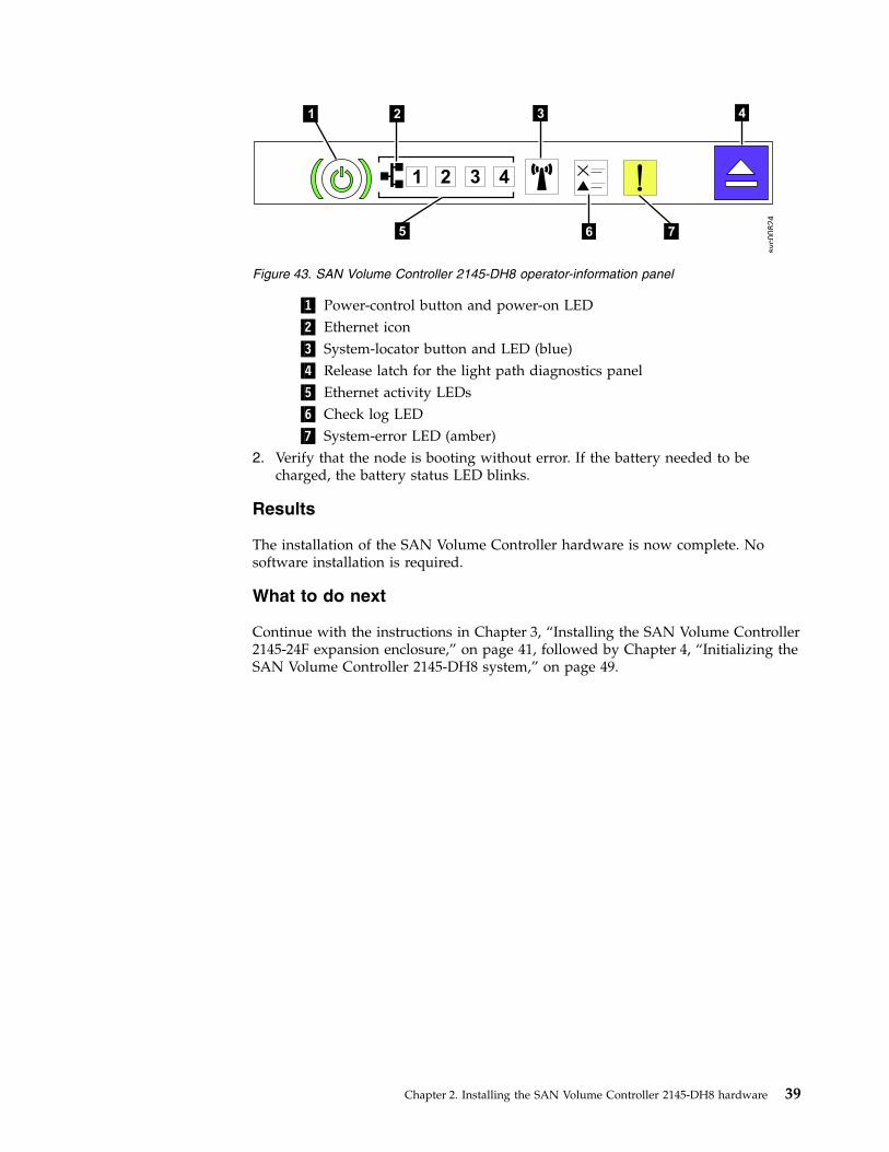
▌1▐ Power-control button and power-on LED▌2▐ Ethernet icon▌3▐ System-locator button and LED (blue)▌4▐ Release latch for the light path diagnostics panel▌5▐ Ethernet activity LEDs▌6▐ Check log LED▌7▐ System-error LED (amber)
2. Verify that the node is booting without error. If the battery needed to becharged, the battery status LED blinks.
Results
The installation of the SAN Volume Controller hardware is now complete. Nosoftware installation is required.
What to do next
Continue with the instructions in Chapter 3, “Installing the SAN Volume Controller2145-24F expansion enclosure,” on page 41, followed by Chapter 4, “Initializing theSAN Volume Controller 2145-DH8 system,” on page 49.
1 2 3 4
5 6 7
svc00824
1 2 3 4
Figure 43. SAN Volume Controller 2145-DH8 operator-information panel
Chapter 2. Installing the SAN Volume Controller 2145-DH8 hardware 39

40 SAN Volume Controller: Model 2145-DH8 Hardware Installation Guide
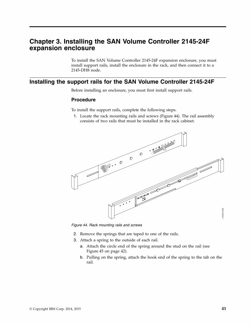
Chapter 3. Installing the SAN Volume Controller 2145-24Fexpansion enclosure
To install the SAN Volume Controller 2145-24F expansion enclosure, you mustinstall support rails, install the enclosure in the rack, and then connect it to a2145-DH8 node.
Installing the support rails for the SAN Volume Controller 2145-24FBefore installing an enclosure, you must first install support rails.
Procedure
To install the support rails, complete the following steps.1. Locate the rack mounting rails and screws (Figure 44). The rail assembly
consists of two rails that must be installed in the rack cabinet.
2. Remove the springs that are taped to one of the rails.3. Attach a spring to the outside of each rail.
a. Attach the circle end of the spring around the stud on the rail (seeFigure 45 on page 42).
b. Pulling on the spring, attach the hook end of the spring to the tab on therail.
v3500168
Figure 44. Rack mounting rails and screws
© Copyright IBM Corp. 2014, 2015 41
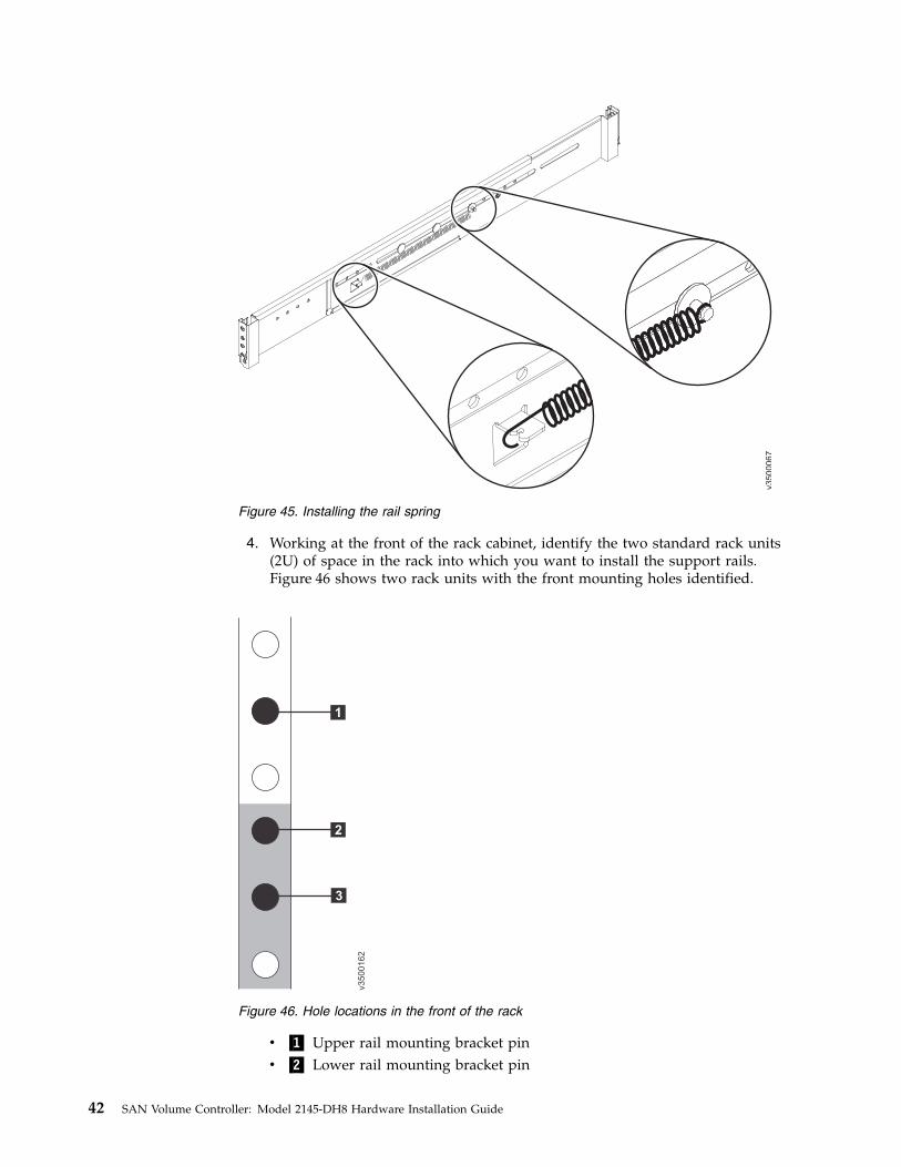
4. Working at the front of the rack cabinet, identify the two standard rack units(2U) of space in the rack into which you want to install the support rails.Figure 46 shows two rack units with the front mounting holes identified.
v ▌1▐ Upper rail mounting bracket pinv ▌2▐ Lower rail mounting bracket pin
v3500067
Figure 45. Installing the rail spring
1
2
3
v3500162
Figure 46. Hole locations in the front of the rack
42 SAN Volume Controller: Model 2145-DH8 Hardware Installation Guide
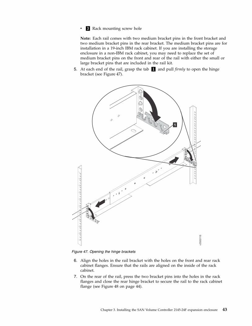
v ▌3▐ Rack mounting screw hole
Note: Each rail comes with two medium bracket pins in the front bracket andtwo medium bracket pins in the rear bracket. The medium bracket pins are forinstallation in a 19-inch IBM rack cabinet. If you are installing the storageenclosure in a non-IBM rack cabinet, you may need to replace the set ofmedium bracket pins on the front and rear of the rail with either the small orlarge bracket pins that are included in the rail kit.
5. At each end of the rail, grasp the tab ▌1▐ and pull firmly to open the hingebracket (see Figure 47).
6. Align the holes in the rail bracket with the holes on the front and rear rackcabinet flanges. Ensure that the rails are aligned on the inside of the rackcabinet.
7. On the rear of the rail, press the two bracket pins into the holes in the rackflanges and close the rear hinge bracket to secure the rail to the rack cabinetflange (see Figure 48 on page 44).
v3500116
1
Figure 47. Opening the hinge brackets
Chapter 3. Installing the SAN Volume Controller 2145-24F expansion enclosure 43
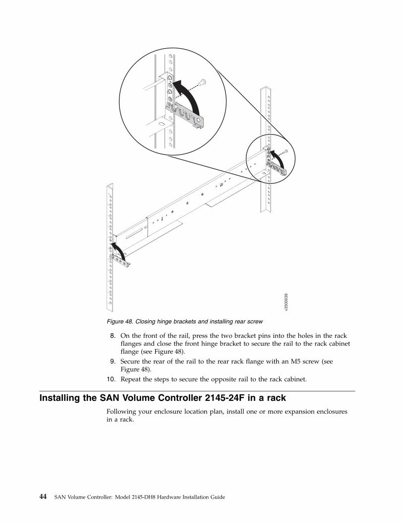
8. On the front of the rail, press the two bracket pins into the holes in the rackflanges and close the front hinge bracket to secure the rail to the rack cabinetflange (see Figure 48).
9. Secure the rear of the rail to the rear rack flange with an M5 screw (seeFigure 48).
10. Repeat the steps to secure the opposite rail to the rack cabinet.
Installing the SAN Volume Controller 2145-24F in a rackFollowing your enclosure location plan, install one or more expansion enclosuresin a rack.
v3500039
Figure 48. Closing hinge brackets and installing rear screw
44 SAN Volume Controller: Model 2145-DH8 Hardware Installation Guide
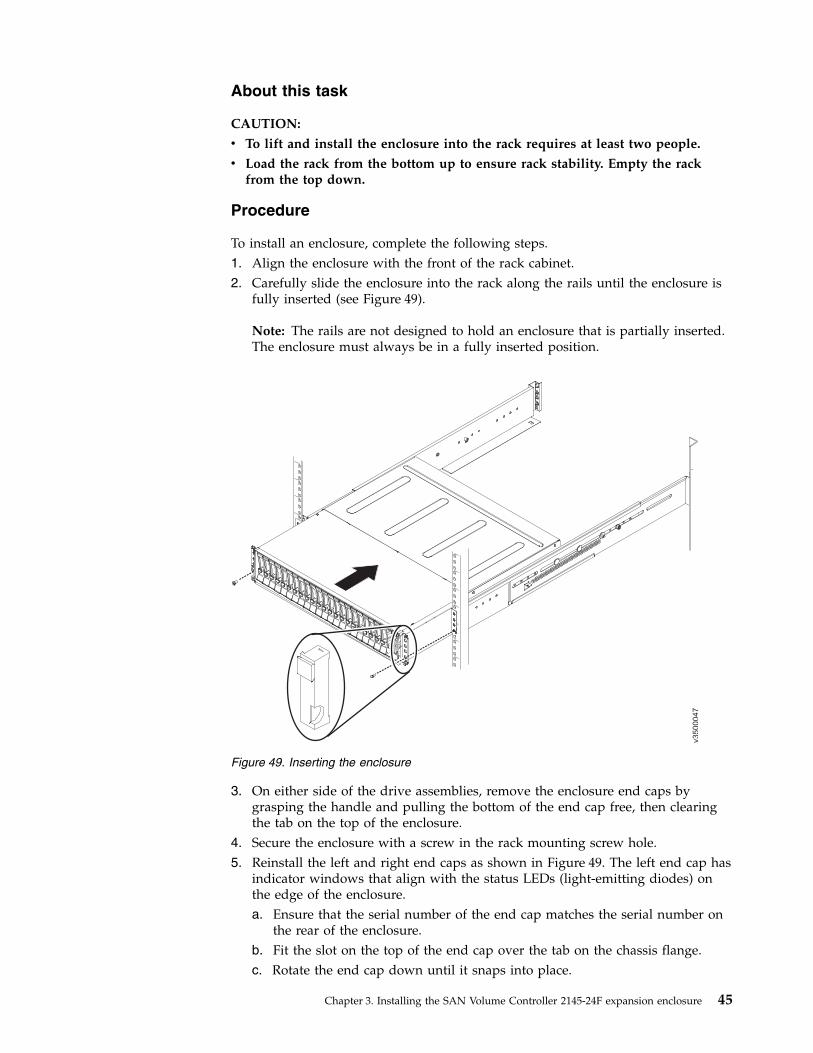
About this task
CAUTION:
v To lift and install the enclosure into the rack requires at least two people.
v Load the rack from the bottom up to ensure rack stability. Empty the rackfrom the top down.
Procedure
To install an enclosure, complete the following steps.1. Align the enclosure with the front of the rack cabinet.2. Carefully slide the enclosure into the rack along the rails until the enclosure is
fully inserted (see Figure 49).
Note: The rails are not designed to hold an enclosure that is partially inserted.The enclosure must always be in a fully inserted position.
3. On either side of the drive assemblies, remove the enclosure end caps bygrasping the handle and pulling the bottom of the end cap free, then clearingthe tab on the top of the enclosure.
4. Secure the enclosure with a screw in the rack mounting screw hole.5. Reinstall the left and right end caps as shown in Figure 49. The left end cap has
indicator windows that align with the status LEDs (light-emitting diodes) onthe edge of the enclosure.a. Ensure that the serial number of the end cap matches the serial number on
the rear of the enclosure.b. Fit the slot on the top of the end cap over the tab on the chassis flange.c. Rotate the end cap down until it snaps into place.
v3500047
Figure 49. Inserting the enclosure
Chapter 3. Installing the SAN Volume Controller 2145-24F expansion enclosure 45
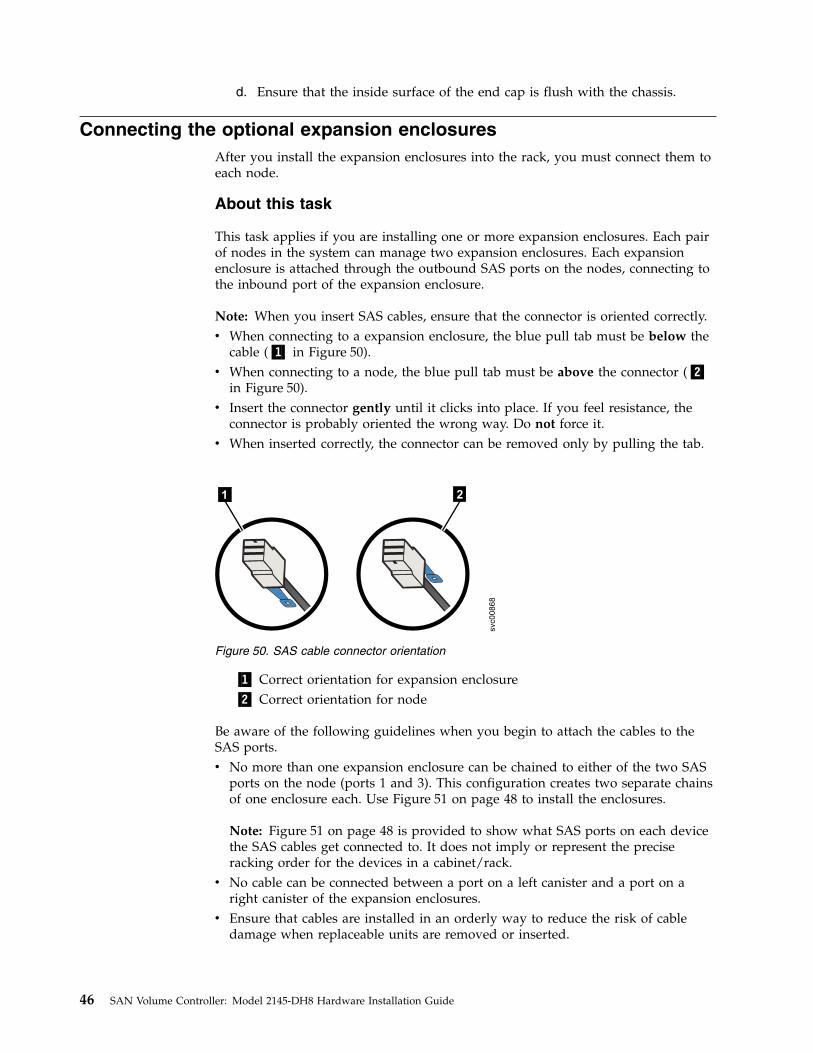
d. Ensure that the inside surface of the end cap is flush with the chassis.
Connecting the optional expansion enclosuresAfter you install the expansion enclosures into the rack, you must connect them toeach node.
About this task
This task applies if you are installing one or more expansion enclosures. Each pairof nodes in the system can manage two expansion enclosures. Each expansionenclosure is attached through the outbound SAS ports on the nodes, connecting tothe inbound port of the expansion enclosure.
Note: When you insert SAS cables, ensure that the connector is oriented correctly.v When connecting to a expansion enclosure, the blue pull tab must be below the
cable (▌1▐ in Figure 50).v When connecting to a node, the blue pull tab must be above the connector (▌2▐
in Figure 50).v Insert the connector gently until it clicks into place. If you feel resistance, the
connector is probably oriented the wrong way. Do not force it.v When inserted correctly, the connector can be removed only by pulling the tab.
▌1▐ Correct orientation for expansion enclosure▌2▐ Correct orientation for node
Be aware of the following guidelines when you begin to attach the cables to theSAS ports.v No more than one expansion enclosure can be chained to either of the two SAS
ports on the node (ports 1 and 3). This configuration creates two separate chainsof one enclosure each. Use Figure 51 on page 48 to install the enclosures.
Note: Figure 51 on page 48 is provided to show what SAS ports on each devicethe SAS cables get connected to. It does not imply or represent the preciseracking order for the devices in a cabinet/rack.
v No cable can be connected between a port on a left canister and a port on aright canister of the expansion enclosures.
v Ensure that cables are installed in an orderly way to reduce the risk of cabledamage when replaceable units are removed or inserted.
1 2svc00868
Figure 50. SAS cable connector orientation
46 SAN Volume Controller: Model 2145-DH8 Hardware Installation Guide
v SAS cables must be routed through the cable management arms to avoid the riskof the nodes getting disconnected from their flash drive arrays or the SAS cablesgetting damaged if the node is slid out on its rails while attached to theenclosure.
v Arrange your cables to provide access to the following components:– Ethernet ports, including the technician port. The technician port is used for
initial setup of the system by directly attaching to a personal computer. It canalso be used to complete service actions for the system.
– USB ports. USB ports can be used to initialize the system or to performservice-related tasks by using a USB flash drive that contains executable filesfor initializing the system.
– Fibre Channel and Fibre Channel over Ethernet (FCoE) ports. If your systemhas an optionally installed Fibre Channel and FCoE adapter for host andexternal storage attachment, ensure that these ports are accessible.
– The nodes and the enclosures themselves. Access is required to the hardwarefor servicing and for safely removing and replacing components by using twoor more people.
Procedure
To install the cables, complete the following steps.1. Using the supplied SAS cables, connect the top node ▌2▐ to the expansion
enclosures, as shown in Figure 51 on page 48.a. Connect SAS port 1 of the top node ▌2▐ to SAS port 1 of the left canister in
the first expansion enclosure ▌1▐.b. Connect SAS port 3 of the top node ▌2▐ to SAS port 1 of the left canister in
the second expansion enclosure ▌4▐.
Chapter 3. Installing the SAN Volume Controller 2145-24F expansion enclosure 47
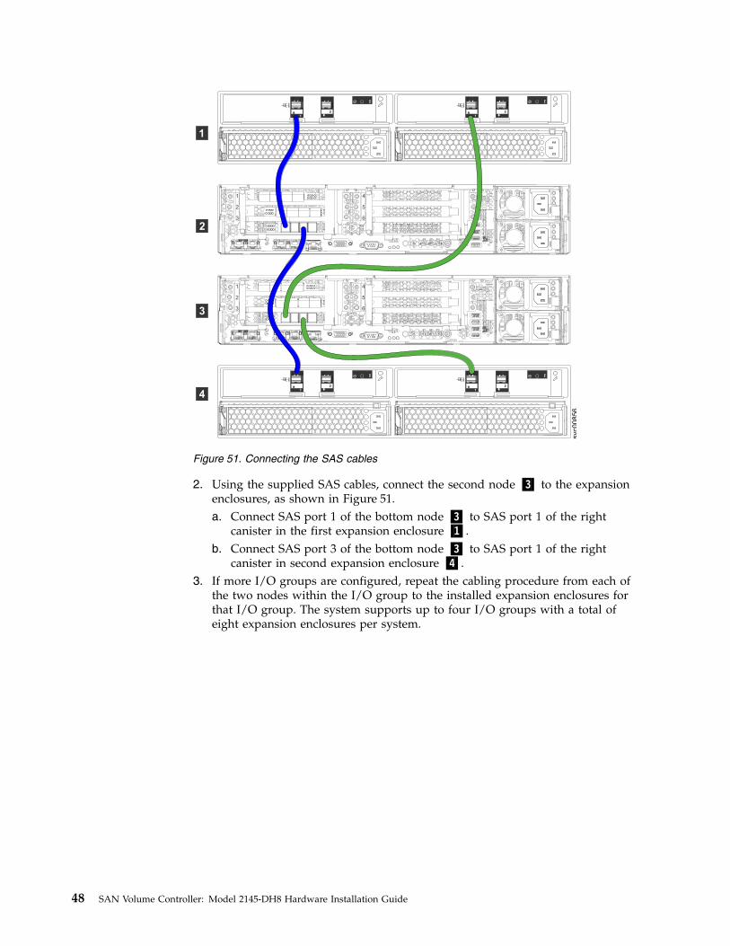
2. Using the supplied SAS cables, connect the second node ▌3▐ to the expansionenclosures, as shown in Figure 51.a. Connect SAS port 1 of the bottom node ▌3▐ to SAS port 1 of the right
canister in the first expansion enclosure ▌1▐.b. Connect SAS port 3 of the bottom node ▌3▐ to SAS port 1 of the right
canister in second expansion enclosure ▌4▐.3. If more I/O groups are configured, repeat the cabling procedure from each of
the two nodes within the I/O group to the installed expansion enclosures forthat I/O group. The system supports up to four I/O groups with a total ofeight expansion enclosures per system.
1
2
3
4
5
6
1
2
3
4
5
6
2
1
2
1
svc00856
3
4
1
2
2
1
2
1
Figure 51. Connecting the SAS cables
48 SAN Volume Controller: Model 2145-DH8 Hardware Installation Guide
Chapter 4. Initializing the SAN Volume Controller 2145-DH8system
To begin the initialization process for the San Volume Controller 2145-DH8 system,you access the management GUI. You need to know the default user name andpassword.
Next, you initialize the system by using the technician port.
After you create the system, you must configure it.
Checking your web browser settings for the management GUITo access the management GUI, you must ensure that your web browser issupported and has the appropriate settings enabled.
Before you begin
The management GUI supports the following web browsers:v Mozilla Firefox 41v Mozilla Firefox Extended Support Release (ESR) 38v Microsoft Internet Explorer (IE) 11 and Microsoft Edgev Google Chrome 46
IBM supports higher versions of the browsers if the vendors do not remove ordisable function that the product relies upon. For browser levels higher than theversions that are certified with the product, customer support accepts usage-relatedand defect-related service requests. If the support center cannot re-create the issue,support might request the client to re-create the problem on a certified browserversion. Defects are not accepted for cosmetic differences between browsers orbrowser versions that do not affect the functional behavior of the product. If aproblem is identified in the product, defects are accepted. If a problem is identifiedwith the browser, IBM might investigate potential solutions or work-arounds thatthe client can implement until a permanent solution becomes available.
Procedure
To configure your web browser, follow these steps:1. Enable JavaScript for your web browser.
For Mozilla Firefox, JavaScript is enabled by default and requires no additionalconfiguration.For Microsoft Internet Explorer (IE) running on Microsoft Windows 7:a. In Internet Explorer, click Tools > Internet Options.b. Click Security Settings.c. Click Internet to choose the Internet zone.d. Click Custom Level.e. Scroll down to the Scripting section, and then in Active Scripting, click
Enable.f. Click OK to close Security Settings.
© Copyright IBM Corp. 2014, 2015 49
g. Click Yes to confirm the change for the zone.h. Click OK to close Internet Options.i. Refresh your browser.For Microsoft Internet Explorer (IE) running on Microsoft Windows Server2008:a. In Internet Explorer, click Tools > Internet Options.b. Click Security.c. Click Trusted sites.d. On the Trusted sites dialog, verify that the web address for the
management GUI is correct and click Add.e. Verify that the correct web address was added to the Trusted sites dialog.f. Click Close on the Trusted sites dialog.g. Click OK.h. Refresh your browser.For Google Chrome:a. On the menu bar in the Google Chrome browser window, click Settings.b. Click Show advanced settings.c. In the Privacy section, click Content settings.d. In the JavaScript section, select Allow all sites to run JavaScript.e. Click OK.f. Refresh your browser.
2. Enable cookies in your web browser.For Mozilla Firefox:a. On the menu bar in the Firefox browser window, click Tools > Options.b. On the Options window, select Privacy.c. Set "Firefox will" to Use custom settings for history.d. Select Accept cookies from sites to enable cookies.e. Click OK.f. Refresh the browser.For Microsoft Internet Explorer:a. In Internet Explorer, click Tools > Internet Options.b. Click Privacy. Under Settings, move the slider to the bottom to allow all
cookies.c. Click OK.d. Refresh your browser.For Google Chrome:a. On the menu bar in the Google Chrome browser window, click Settings.b. Click Show advanced settings.c. In the Privacy section, click Content settings.d. In the Cookies section, select Allow local data to be set.e. Click OK.f. Refresh your browser.
3. Enable file download on IE 10 and 11 running on Windows 2012.a. In Internet Explorer, click Tools > Internet Options.b. On the Internet Options window, select the Security tab.
50 SAN Volume Controller: Model 2145-DH8 Hardware Installation Guide
c. On the Security tab, click the Internet zone.d. Click Custom level to customize the security level for this zone.e. Scroll down to Downloads and select Enable under File download.f. Click OK.g. Click Yes to confirm.h. Click OK to close the Internet Options.
4. Enable scripts to disable or replace context menus. (Mozilla Firefox only).For Mozilla Firefox:a. On the menu bar in the Firefox browser window, click Tools > Options.b. On the Options window, select Content.c. Click Advanced by the Enable JavaScript setting.d. Select Disable or replace context menus.e. Click OK to close the Advanced window.f. Click OK to close the Options window.g. Refresh your browser.
5. Enable TLS 1.1/1.2 (Microsoft Internet Explorer 9 and 10 only).For Microsoft Internet Explorer:a. Open Internet Explorer.b. Select Tools > Internet Options.c. Select the Advanced tab.d. Scroll to the Security section.e. Check the Use TLS 1.1 and Use TLS 1.2 checkboxes.
Note: IE 11 and later enable TLS 1.1/1.2 by default.
User name and password for system initializationDuring the initialization procedure, you need to log in to the management GUI forthe SAN Volume Controller system.
The default user name and password for the management GUI are listed in Table 8.
Table 8. Default user name and password for the management GUI
User name Password
superuser passw0rd
Note: The 0 character in the password is a zero, not the letter O.
Initializing the system by using the technician portTo initialize a new system, you must connect a personal computer to the technicianport on the rear of a node and run the initialization tool. This node becomes theconfiguration node and provides access to the management GUI. Access themanagement GUI by using the management IP address through your IP networkor through the technician port. Use the management GUI to add each candidatenode to the system.
Chapter 4. Initializing the SAN Volume Controller 2145-DH8 system 51
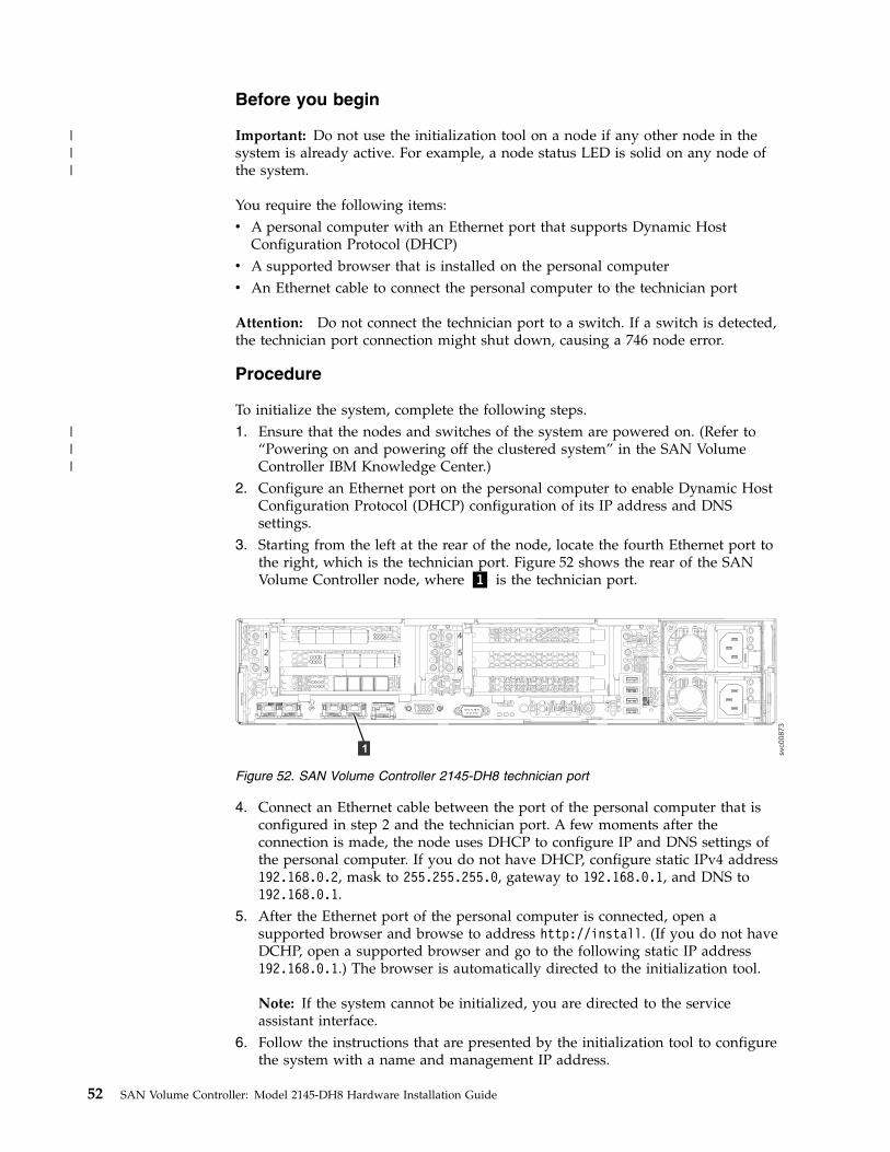
Before you begin
Important: Do not use the initialization tool on a node if any other node in thesystem is already active. For example, a node status LED is solid on any node ofthe system.
You require the following items:v A personal computer with an Ethernet port that supports Dynamic Host
Configuration Protocol (DHCP)v A supported browser that is installed on the personal computerv An Ethernet cable to connect the personal computer to the technician port
Attention: Do not connect the technician port to a switch. If a switch is detected,the technician port connection might shut down, causing a 746 node error.
Procedure
To initialize the system, complete the following steps.1. Ensure that the nodes and switches of the system are powered on. (Refer to
“Powering on and powering off the clustered system” in the SAN VolumeController IBM Knowledge Center.)
2. Configure an Ethernet port on the personal computer to enable Dynamic HostConfiguration Protocol (DHCP) configuration of its IP address and DNSsettings.
3. Starting from the left at the rear of the node, locate the fourth Ethernet port tothe right, which is the technician port. Figure 52 shows the rear of the SANVolume Controller node, where ▌1▐ is the technician port.
4. Connect an Ethernet cable between the port of the personal computer that isconfigured in step 2 and the technician port. A few moments after theconnection is made, the node uses DHCP to configure IP and DNS settings ofthe personal computer. If you do not have DHCP, configure static IPv4 address192.168.0.2, mask to 255.255.255.0, gateway to 192.168.0.1, and DNS to192.168.0.1.
5. After the Ethernet port of the personal computer is connected, open asupported browser and browse to address http://install. (If you do not haveDCHP, open a supported browser and go to the following static IP address192.168.0.1.) The browser is automatically directed to the initialization tool.
Note: If the system cannot be initialized, you are directed to the serviceassistant interface.
6. Follow the instructions that are presented by the initialization tool to configurethe system with a name and management IP address.
svc00873
1
2
3
4
5
6
1
Figure 52. SAN Volume Controller 2145-DH8 technician port
52 SAN Volume Controller: Model 2145-DH8 Hardware Installation Guide
|||
|||
7. If you experience a problem during the process due to a change in systemstates, wait 5 - 10 seconds. Then, either reopen the SSH connection or reloadthe service assistant.
8. After you complete the initialization process, disconnect the cable between thepersonal computer and the technician port.
What to do next
The system management GUI can now be reached by opening a supported webbrowser and pointing it to http://management_IP_address. Use the managementGUI to add each candidate node to the system. Then, it is best to use themanagement GUI to set the service IP address for each node now. Ensure that thesystem is disconnected from the technician port.
Adding nodes to an existing clustered systemBefore you add a node to an existing system, consider this high-level overview ofthe requirements and tasks involved.
Before you begin
This task requires that the following conditions are met:v All nodes that are configured in the system are present. Nodes must be installed
in pairs. Each pair of nodes is an I/O group.v All errors in the system event log are fixed.v All managed disks (MDisks) are online.v A node with only Fibre Channel over Ethernet (FCoE) ports (all FCoE ports)
connected to the switch and properly zoned can also be added to an I/O group.
About this task
Table 9 lists the models and software version requirements for nodes.
Table 9. Node model names and software version requirements
Node modelRequired system SAN Volume Controllersoftware version
SAN Volume Controller 2145-DH8 7.3.0.0 or later
SAN Volume Controller 2145-CG8with two Fibre Channel adapters
6.4.1.5 or later (any partner systems must have6.4.0 or later)
SAN Volume Controller 2145-CG8 6.2.0 or later
SAN Volume Controller 2145-CF8 5.1.0 or later
Note: The steps in the following procedure refer to uninterruptible power supplyunits. SAN Volume Controller 2145-DH8 does not have an external uninterruptiblepower supply unit. This system has battery modules in its front panel instead.
Procedure1. Install the SAN Volume Controller nodes, and if applicable the uninterruptible
power supply units, in the rack.2. Connect the SAN Volume Controller nodes to the LAN.3. Connect the SAN Volume Controller nodes to the SAN fabric.
Chapter 4. Initializing the SAN Volume Controller 2145-DH8 system 53
4. Power on the SAN Volume Controller nodes and, if applicable, theuninterruptible power supply units.
5. Zone the SAN Volume Controller node ports in the existing SAN VolumeController zone. The SAN Volume Controller zone exists in each fabric withonly node ports.
6. Zone the SAN Volume Controller node ports in the existing SAN VolumeController and storage zone. A storage zone contains all of the SAN VolumeController node ports and storage system ports that are in the fabric and usedto access the physical disks.
7. For each storage system that is used with the SAN Volume Controller clusteredsystem, use the system management application to map the LUNs that arecurrently used by the clustered system to all of the WWPNs of the SANVolume Controller nodes that you want to add. The SAN Volume Controllernodes must recognize the same LUNs that the existing nodes in the clusteredsystem can recognize before they can be added. If the SAN Volume Controllernodes cannot recognize the same LUNs, the storage system is markeddegraded.
8. Add the SAN Volume Controller nodes to the clustered system.9. Check the status of the storage systems and MDisks to ensure that status is not
marked degraded. If the status is degraded, a configuration problem must beresolved before you can do any further system configuration task. If theproblem cannot be resolved, remove the newly added SAN Volume Controllernodes from the clustered system and contact the IBM Support Center forassistance.
What to do next
For specific instructions about adding a new node or adding a replacement node toa clustered system, see the information about adding nodes to a clustered systemin the IBM SAN Volume Controller Troubleshooting Guide.
54 SAN Volume Controller: Model 2145-DH8 Hardware Installation Guide
Appendix A. Accessibility features for IBM SAN VolumeController
Accessibility features help users who have a disability, such as restricted mobilityor limited vision, to use information technology products successfully.
Accessibility features
These are the major accessibility features for the SAN Volume Controller:v You can use screen-reader software and a digital speech synthesizer to hear what
is displayed on the screen. HTML documents have been tested using JAWSversion 15.0.
v This product uses standard Windows navigation keys.v Interfaces are commonly used by screen readers.v Keys are discernible by touch, but do not activate just by touching them.v Industry-standard devices, ports, and connectors.v You can attach alternative input and output devices.
The SAN Volume Controller online documentation and its related publications areaccessibility-enabled. The accessibility features of the online documentation aredescribed in Viewing information in the information center .
Keyboard navigation
You can use keys or key combinations to perform operations and initiate menuactions that can also be done through mouse actions. You can navigate the SANVolume Controller online documentation from the keyboard by using the shortcutkeys for your browser or screen-reader software. See your browser or screen-readersoftware Help for a list of shortcut keys that it supports.
IBM and accessibility
See the IBM Human Ability and Accessibility Center for more information aboutthe commitment that IBM has to accessibility.
© Copyright IBM Corp. 2014, 2015 55

56 SAN Volume Controller: Model 2145-DH8 Hardware Installation Guide

Appendix B. Where to find the Statement of Limited Warranty
The Statement of Limited Warranty is available in both hardcopy format and in theSAN Volume Controller information center.
The Statement of Limited Warranty is shipped (in hardcopy form) with yourproduct. It can also be ordered from IBM (see Table 2 on page xxvi for the partnumber).
© Copyright IBM Corp. 2014, 2015 57

58 SAN Volume Controller: Model 2145-DH8 Hardware Installation Guide

Appendix C. SAN Volume Controller physical installationplanning
Before the IBM service representative can set up your environment, you mustverify that the prerequisite conditions for system installation are met.
SAN Volume Controller 2145-DH8 environment requirementsBefore the SAN Volume Controller 2145-DH8 is installed, the physical environmentmust meet certain requirements. This includes verifying that adequate space isavailable and that requirements for power and environmental conditions are met.
Input-voltage requirements
Ensure that your environment meets the voltage requirements that are shown inTable 10.
Table 10. Input-voltage requirements
Voltage Frequency
100-127 / 200-240Vac 50 Hz or 60 Hz
Maximum power requirements for each node
Ensure that your environment meets the power requirements as shown in Table 11.
The maximum power that is required depends on the node type and the optionalfeatures that are installed.
Table 11. Maximum power consumption
Components Power requirements
SAN Volume Controller 2145-DH8 750 W
Note: You cannot mix ac and dc power sources; the power sources must match.
Environment requirements without redundant AC power
Ensure that your environment falls within the following ranges if you are notusing redundant AC power.
If you are not using redundant ac power, ensure that your environment fallswithin the ranges that are shown in Table 12 on page 60.
© Copyright IBM Corp. 2014, 2015 59
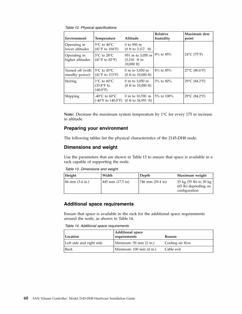
Table 12. Physical specifications
Environment Temperature AltitudeRelativehumidity
Maximum dewpoint
Operating inlower altitudes
5°C to 40°C(41°F to 104°F)
0 to 950 m(0 ft to 3,117 ft)
8% to 85% 24°C (75°F)Operating inhigher altitudes
5°C to 28°C(41°F to 82°F)
951 m to 3,050 m(3,118 ft to10,000 ft)
Turned off (withstandby power)
5°C to 45°C(41°F to 113°F)
0 m to 3,050 m(0 ft to 10,000 ft)
8% to 85% 27°C (80.6°F)
Storing 1°C to 60°C(33.8°F to140.0°F)
0 m to 3,050 m(0 ft to 10,000 ft)
5% to 80% 29°C (84.2°F)
Shipping -40°C to 60°C(-40°F to 140.0°F)
0 m to 10,700 m(0 ft to 34,991 ft)
5% to 100% 29°C (84.2°F)
Note: Decrease the maximum system temperature by 1°C for every 175 m increasein altitude.
Preparing your environment
The following tables list the physical characteristics of the 2145-DH8 node.
Dimensions and weight
Use the parameters that are shown in Table 13 to ensure that space is available in arack capable of supporting the node.
Table 13. Dimensions and weight
Height Width Depth Maximum weight
86 mm (3.4 in.) 445 mm (17.5 in) 746 mm (29.4 in) 25 kg (55 lb) to 30 kg(65 lb) depending onconfiguration
Additional space requirements
Ensure that space is available in the rack for the additional space requirementsaround the node, as shown in Table 14.
Table 14. Additional space requirements
LocationAdditional spacerequirements Reason
Left side and right side Minimum: 50 mm (2 in.) Cooling air flow
Back Minimum: 100 mm (4 in.) Cable exit
60 SAN Volume Controller: Model 2145-DH8 Hardware Installation Guide
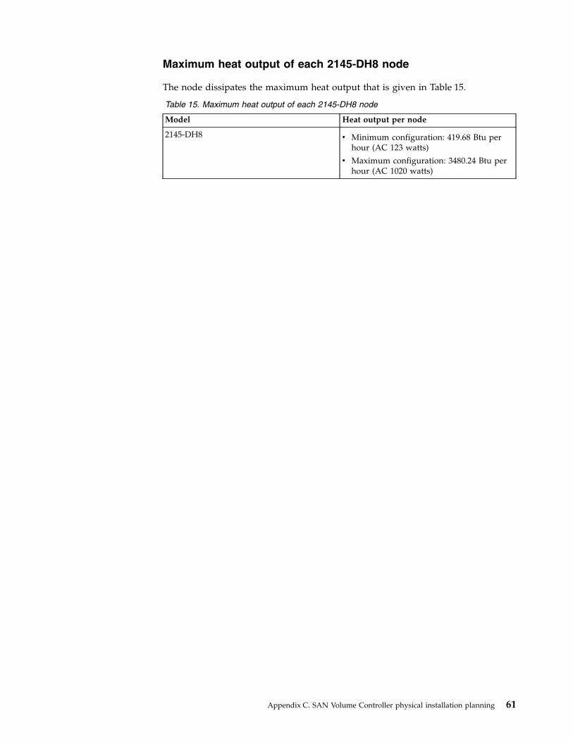
Maximum heat output of each 2145-DH8 node
The node dissipates the maximum heat output that is given in Table 15.
Table 15. Maximum heat output of each 2145-DH8 node
Model Heat output per node
2145-DH8 v Minimum configuration: 419.68 Btu perhour (AC 123 watts)
v Maximum configuration: 3480.24 Btu perhour (AC 1020 watts)
Appendix C. SAN Volume Controller physical installation planning 61

62 SAN Volume Controller: Model 2145-DH8 Hardware Installation Guide
Notices
This information was developed for products and services offered in the US. Thismaterial might be available from IBM in other languages. However, you may berequired to own a copy of the product or product version in that language in orderto access it.
IBM may not offer the products, services, or features discussed in this document inother countries. Consult your local IBM representative for information on theproducts and services currently available in your area. Any reference to an IBMproduct, program, or service is not intended to state or imply that only that IBMproduct, program, or service may be used. Any functionally equivalent product,program, or service that does not infringe any IBM intellectual property right maybe used instead. However, it is the user's responsibility to evaluate and verify theoperation of any non-IBM product, program, or service.
IBM may have patents or pending patent applications covering subject matterdescribed in this document. The furnishing of this document does not grant youany license to these patents. You can send license inquiries, in writing, to:
IBM Director of LicensingIBM CorporationNorth Castle DriveArmonk, NY 10504-1785U.S.A.
For license inquiries regarding double-byte character set (DBCS) information,contact the IBM Intellectual Property Department in your country or sendinquiries, in writing, to:
Intellectual Property LicensingLegal and Intellectual Property LawIBM Japan, Ltd.19-21, Nihonbashi-Hakozakicho, Chuo-kuTokyo 103-8510, Japan
INTERNATIONAL BUSINESS MACHINES CORPORATION PROVIDES THISPUBLICATION "AS IS" WITHOUT WARRANTY OF ANY KIND, EITHEREXPRESS OR IMPLIED, INCLUDING, BUT NOT LIMITED TO, THE IMPLIEDWARRANTIES OF NON-INFRINGEMENT, MERCHANTABILITY OR FITNESSFOR A PARTICULAR PURPOSE. Some jurisdictions do not allow disclaimer ofexpress or implied warranties in certain transactions, therefore, this statement maynot apply to you.
This information could include technical inaccuracies or typographical errors.Changes are periodically made to the information herein; these changes will beincorporated in new editions of the publication. IBM may make improvementsand/or changes in the product(s) and/or the program(s) described in thispublication at any time without notice.
Any references in this information to non-IBM websites are provided forconvenience only and do not in any manner serve as an endorsement of those
© Copyright IBM Corp. 2014, 2015 63
websites. The materials at those websites are not part of the materials for this IBMproduct and use of those websites is at your own risk.
IBM may use or distribute any of the information you provide in any way itbelieves appropriate without incurring any obligation to you.
Licensees of this program who wish to have information about it for the purposeof enabling: (i) the exchange of information between independently createdprograms and other programs (including this one) and (ii) the mutual use of theinformation which has been exchanged, should contact:
IBM Director of LicensingIBM CorporationNorth Castle Drive, MD-NC119Armonk, NY 10504-1785US
Such information may be available, subject to appropriate terms and conditions,including in some cases, payment of a fee.
The licensed program described in this document and all licensed materialavailable for it are provided by IBM under terms of the IBM Customer Agreement,IBM International Program License Agreement or any equivalent agreementbetween us.
The performance data discussed herein is presented as derived under specificoperating conditions. Actual results may vary.
Information concerning non-IBM products was obtained from the suppliers ofthose products, their published announcements or other publicly available sources.IBM has not tested those products and cannot confirm the accuracy ofperformance, compatibility or any other claims related to non-IBM products.Questions on the capabilities of non-IBM products should be addressed to thesuppliers of those products.
Statements regarding IBM's future direction or intent are subject to change orwithdrawal without notice, and represent goals and objectives only.
All IBM prices shown are IBM's suggested retail prices, are current and are subjectto change without notice. Dealer prices may vary.
This information is for planning purposes only. The information herein is subject tochange before the products described become available.
This information contains examples of data and reports used in daily businessoperations. To illustrate them as completely as possible, the examples include thenames of individuals, companies, brands, and products. All of these names arefictitious and any similarity to the names and addresses used by an actual businessenterprise is entirely coincidental.
COPYRIGHT LICENSE:
This information contains sample application programs in source language, whichillustrate programming techniques on various operating platforms. You may copy,modify, and distribute these sample programs in any form without payment toIBM, for the purposes of developing, using, marketing or distributing application
64 SAN Volume Controller: Model 2145-DH8 Hardware Installation Guide
programs conforming to the application programming interface for the operatingplatform for which the sample programs are written. These examples have notbeen thoroughly tested under all conditions. IBM, therefore, cannot guarantee orimply reliability, serviceability, or function of these programs. The sampleprograms are provided "AS IS", without warranty of any kind. IBM shall not beliable for any damages arising out of your use of the sample programs.
If you are viewing this information softcopy, the photographs and colorillustrations may not appear.
TrademarksIBM, the IBM logo, and ibm.com® are trademarks or registered trademarks ofInternational Business Machines Corp., registered in many jurisdictions worldwide.Other product and service names might be trademarks of IBM or other companies.A current list of IBM trademarks is available on the web at Copyright andtrademark information at www.ibm.com/legal/copytrade.shtml.
Adobe, the Adobe logo, PostScript, and the PostScript logo are either registeredtrademarks or trademarks of Adobe Systems Incorporated in the United States,and/or other countries.
Microsoft, Windows, and the Windows logo are trademarks of MicrosoftCorporation in the United States, other countries, or both.
Other product and service names might be trademarks of IBM or other companies.
Homologation statementThis product may not be certified in your country for connection by any meanswhatsoever to interfaces of public telecommunications networks. Furthercertification may be required by law prior to making any such connection. Contactan IBM representative or reseller for any questions.
Electronic emission noticesThis section contains the electronic emission notices or statements for the UnitedStates and other countries.
Federal Communications Commission (FCC) statementThis explains the Federal Communications Commission's (FCC’s) statement.
This equipment has been tested and found to comply with the limits for a Class Adigital device, pursuant to Part 15 of the FCC Rules. These limits are designed toprovide reasonable protection against harmful interference when the equipment isoperated in a commercial environment. This equipment generates, uses, and canradiate radio frequency energy and, if not installed and used in accordance withthe instruction manual, might cause harmful interference to radio communications.Operation of this equipment in a residential area is likely to cause harmfulinterference, in which case the user will be required to correct the interference athis own expense.
Properly shielded and grounded cables and connectors must be used in order tomeet FCC emission limits. IBM is not responsible for any radio or televisioninterference caused by using other than recommended cables and connectors, or by
Notices 65

unauthorized changes or modifications to this equipment. Unauthorized changesor modifications could void the user's authority to operate the equipment.
This device complies with Part 15 of the FCC Rules. Operation is subject to thefollowing two conditions: (1) this device might not cause harmful interference, and(2) this device must accept any interference received, including interference thatmight cause undesired operation.
Industry Canada compliance statement
This Class A digital apparatus complies with Canadian ICES-003.
Cet appareil numérique de la classe A est conform à la norme NMB-003 duCanada.
Australia and New Zealand Class A StatementAttention: This is a Class A product. In a domestic environment this productmight cause radio interference in which case the user might be required to takeadequate measures.
European Union Electromagnetic Compatibility DirectiveThis product is in conformity with the protection requirements of European Union(EU) Council Directive 2004/108/EC on the approximation of the laws of theMember States relating to electromagnetic compatibility. IBM cannot acceptresponsibility for any failure to satisfy the protection requirements resulting from anon-recommended modification of the product, including the fitting of non-IBMoption cards.
Attention: This is an EN 55022 Class A product. In a domestic environment thisproduct might cause radio interference in which case the user might be required totake adequate measures.
Responsible Manufacturer:
International Business Machines Corp.New Orchard RoadArmonk, New York 10504914-499-1900
European community contact:
IBM Deutschland GmbHTechnical Regulations, Department M372IBM-Allee 1, 71139 Ehningen, GermanyTele: +49 (0) 800 225 5423 or +49 (0) 180 331 3233Email: [email protected]
Germany Electromagnetic Compatibility DirectiveDeutschsprachiger EU Hinweis: Hinweis für Geräte der Klasse A EU-Richtliniezur Elektromagnetischen Verträglichkeit
66 SAN Volume Controller: Model 2145-DH8 Hardware Installation Guide
Dieses Produkt entspricht den Schutzanforderungen der EU-Richtlinie2004/108/EG zur Angleichung der Rechtsvorschriften über die elektromagnetischeVerträglichkeit in den EU-Mitgliedsstaaten und hält die Grenzwerte der EN 55022Klasse A ein.
Um dieses sicherzustellen, sind die Geräte wie in den Handbüchern beschrieben zuinstallieren und zu betreiben. Des Weiteren dürfen auch nur von der IBMempfohlene Kabel angeschlossen werden. IBM übernimmt keine Verantwortung fürdie Einhaltung der Schutzanforderungen, wenn das Produkt ohne Zustimmung derIBM verändert bzw. wenn Erweiterungskomponenten von Fremdherstellern ohneEmpfehlung der IBM gesteckt/eingebaut werden.
EN 55022 Klasse A Geräte müssen mit folgendem Warnhinweis versehen werden:
“Warnung: Dieses ist eine Einrichtung der Klasse A. Diese Einrichtung kann imWohnbereich Funk-Störungen verursachen; in diesem Fall kann vom Betreiberverlangt werden, angemessene Mabnahmen zu ergreifen und dafüraufzukommen.”
Deutschland: Einhaltung des Gesetzes über die elektromagnetischeVerträglichkeit von Geräten
Dieses Produkt entspricht dem “Gesetz über die elektromagnetische Verträglichkeitvon Geräten (EMVG).” Dies ist die Umsetzung der EU-Richtlinie 2004/108/EG inder Bundesrepublik Deutschland.
Zulassungsbescheinigung laut dem Deutschen Gesetz über dieelektromagnetische Verträglichkeit von Geräten (EMVG) (bzw. der EMC EGRichtlinie 2004/108/EG) für Geräte der Klasse A
Dieses Gerät ist berechtigt, in übereinstimmung mit dem Deutschen EMVG dasEG-Konformitätszeichen - CE - zu führen.
Verantwortlich für die Einhaltung der EMV Vorschriften ist der Hersteller:
International Business Machines Corp.New Orchard RoadArmonk,New York 10504Tel: 914-499-1900
Der verantwortliche Ansprechpartner des Herstellers in der EU ist:
IBM Deutschland GmbHTechnical Regulations, Abteilung M372IBM-Allee 1, 71139 Ehningen, GermanyTele: +49 (0) 800 225 5423 or +49 (0) 180 331 3233Email: [email protected]
Generelle Informationen:
Das Gerät erfüllt die Schutzanforderungen nach EN 55024 und EN 55022 KlasseA.
People's Republic of China Class A Statement
Notices 67
Taiwan Class A compliance statement
Taiwan Contact InformationThis topic contains the product service contact information for Taiwan.IBM Taiwan Product Service Contact Information:IBM Taiwan Corporation3F, No 7, Song Ren Rd., Taipei TaiwanTel: 0800-016-888
Japan VCCI Council Class A statementThis explains the Japan Voluntary Control Council for Interference (VCCI)statement.
Japan Electronics and Information Technology IndustriesAssociation Statement
This explains the Japan Electronics and Information Technology IndustriesAssociation (JEITA) statement for less than or equal to 20 A per phase.
f2c0
07
90
68 SAN Volume Controller: Model 2145-DH8 Hardware Installation Guide
This explains the JEITA statement for greater than 20 A per phase.
Korean Communications Commission Class A StatementThis explains the Korean Communications Commission (KCC) statement.
Russia Electromagnetic Interference Class A StatementThis statement explains the Russia Electromagnetic Interference (EMI) statement.
jjieta
1
jjieta
2
rusem
i
Notices 69

70 SAN Volume Controller: Model 2145-DH8 Hardware Installation Guide
Index
Numerics10 Gbps Ethernet adapter
activity LED 92145-DH8
additional space requirements 60air temperature without redundant ac
power 59dimensions and weight 60heat output of node 61humidity without redundant ac
power 59input-voltage requirements 59nodes
heat output 61power requirements for each
node 59product characteristics 59requirements 59specifications 59weight and dimensions 60
Aabout this guide xxvAC and DC LEDs 7accessibility 55
repeat rateup and down buttons 55
accessingpublications 55
Bback-panel assembly
SAN Volume Controller 2145-DH8connectors 11indicators 6
battery fault LED 3battery status LED 3browsers
See web browsers
Ccable management arm assembly 25Canadian electronic emission notice 66caution ixcaution notices xcharts and tables
for planning 15checking grounding xxiiclustered systems
adding nodes 53comments xxixconfiguration
web browserssettings 49
connectorsSAN Volume Controller 2145-DH8 11
consoleSAN Volume Controller
master console 1contact information
Taiwan 68controls and indicators on the front panel
SAN Volume Controller 2145-DH8illustration 2operator-information panel 4
Ddanger ixdanger notices xiiiDeutschsprachiger EU Hinweis 66
Eelectronic emission notices
Deutschsprachiger EU Hinweis 66European Union (EU) 66Federal Communications Commission
(FCC) 65Germany 66Industry Canada 66Japanese Voluntary Control Council
for Interference (VCCI) 68Korean 69New Zealand 66People's Republic of China 67Taiwan 68
electronic emissions notices 68EMC statement, People's Republic of
China 67emergency power-off (EPO) event xxiienvironmental notices ix, xxiiiEPO (emergency power-off) event xxiiEthernet
activity LED 9connecting to 35link LED 9SAN Volume Controller
2145-DH8 35Ethernet activity LEDs 5European Union (EU), EMC Directive
conformance statement 66expansion enclosure
attachment cables 46external device safety check xxi
FFCC (Federal Communications
Commission) electronic emissionnotice 65
Federal Communications Commission(FCC) electronic emission notice 65
feedback xxixFibre Channel
LEDs 6
GGermany electronic emission compliance
statement 66guidelines, installation 19
Hhazards xxhelp xxixhomologation statement 65
Iidentify button 5identify LED 5IEC 60950-1 ixindicators and controls on the front panel
SAN Volume Controller 2145-DH8illustration 2operator-information panel 4
indicators on the rear panel10 Gbps Ethernet adapter 9AC and DC LEDs 7Ethernet
activity LED 9link LED 9
Ethernet activity LED 9Fibre Channel LEDs 6power-supply error LED 7power, location, and system-error
LEDs 8information center xxviinformation help xxixinitializing the system 52inspections, safety
external device check xxiinternal device check xxiSAN Volume Controller xx
installationguidelines 19planning for SAN Volume
Controller 59preparing for 15requirements 15verifying
SAN Volume Controller2145-DH8 37
installinghardware 15overview xxxiiiSAN Volume Controller 2145-DH8
in a rack 34preparation 15steps 18support rails 19
stepsSAN Volume Controller
2145-DH8 18
© Copyright IBM Corp. 2014, 2015 71
installing (continued)support rails
SAN Volume Controller2145-DH8 19
internal device safety check xxi
JJapan Electronics and Information
Technology Industries AssociationStatement 68
Japanese electronic emission notice 68
Kkeyboards
accessibility features 55Korean electronic emission statement 69
Llabels ixLEDs
AC and DC 7Ethernet
activity 9link 9
Fibre Channel 6location 8power 8power-supply error 7rear-panel indicators 6SAN Volume Controller 2145-DH8 6system-error 8
Nnavigation
accessibility 55New Zealand electronic emission
statement 66node fault LED 3node status LED 3nodes
adding 53non-IBM Alteration form xxinot used
location LED 8notices ix
environmental ix, xxiiisafety ix
Ooperator-information panel
SAN Volume Controller 2145-DH8 4overview
hardware installation 15installing xxxiiiSAN Volume Controller 1
Ppanel
operator informationSAN Volume Controller
2145-DH8 4rear
SAN Volume Controller2145-DH8 6
password 51People's Republic of China, electronic
emission statement 67physical characteristics
SAN Volume Controller 2145-DH8connectors 11service ports 12unused ports 12
planningcharts and tables 15tables and charts 15
planning for SAN Volume Controllerinstallation 59
portsEthernet 9SAN Volume Controller 2145-DH8 11
poweremergency power-off event xxiirequirements
2145-DH8 59power button 5power LED 4power-supply error LED 7preparing
physical configuration 15physical environment 15
publicationsaccessing 55
Rrails 41, 45reader feedback xxixrear-panel indicators
SAN Volume Controller 2145-DH8 6related information xxvirelease latch 6requirements
2145-DH8 59ac voltage 59electrical 59power 59
Ssafety ix
caution notices xdanger notices xiiienvironmental notices ix
safety information labels ixsafety notices ixSAN (storage area network)
connecting to 35SAN Volume Controller
checking grounding xxiifeatures 1hardware 1installation guidelines 19
SAN Volume Controller (continued)installing
overview xxxiiiminimum requirements 1node, components 15overview 1physical configuration 15planning tables and charts 15safety notices x, xiiisoftware
overview 1SAN Volume Controller 2145-24F
installing 45SAN Volume Controller 2145-CG8
LEDspower, location, and
system-error 8power, location, and system-error
LEDs 8SAN Volume Controller 2145-DH8
connectingethernet 35to a SAN 35
connectors 11controls and indicators on the front
panel 2Fibre Channel
LEDs 6port number 13
indicators and controls on the frontpanel 2
indicators on the rear panelFibre Channel LEDs 6
installation, verifying 37installing in a rack 34LEDs
Fibre Channel 6operator-information panel 4ports 11rear-panel indicators 6service ports 12support rails 19unused ports 12
SAN Volume Controller libraryrelated publications xxvi
SAN Volume Controller nodesadding to clustered systems 53
SAS cables 46send a comment xxixservice ports
SAN Volume Controller2145-DH8 12
shortcut keyskeyboard 55
softwareoverview 1
space requirements2145-DH8 60
Statement of Limited Warranty, Where tofind the 57
static-sensitive devices xxiisuperuser 51support rails 41
SAN Volume Controller2145-DH8 19
system-error LED 5system-information LED 5
72 SAN Volume Controller: Model 2145-DH8 Hardware Installation Guide
Ttables and charts, planning 15Taiwan
contact information 68electronic emission notice 68
technical assistance xxixtrademarks 65
Uunused ports
SAN Volume Controller2145-DH8 12
user name 51
Vverifying
installationSAN Volume Controller
2145-DH8 37
Wweb browsers
configuring 49requirements 49
websites xxviiiwho should read this guide xxv
Index 73

74 SAN Volume Controller: Model 2145-DH8 Hardware Installation Guide


IBM®
Part Number: 01AC589
Printed in USA
GC27-6490-04
(1P) P
/N: 01
AC589