Embed Size (px)
Citation preview


Contents
iSCSI configurations .................................................................................... 5Single-network and multi-network single-controller configuration in an iSCSI
SAN ....................................................................................................................... 5
Single-network HA pair in an iSCSI SAN .................................................................. 6
Multi-network HA pair in an iSCSI SAN ................................................................... 6
Direct-attached single-controller configurations in an iSCSI SAN ............................ 7
VLANs for iSCSI configurations ................................................................................ 8
Static VLANs .................................................................................................. 9
Dynamic VLANs ............................................................................................. 9
Fibre Channel configurations .................................................................... 10Recommended number of paths to avoid single points of failure ............................. 10
FC supported hop counts ........................................................................................... 10
FC supported speeds .................................................................................................. 11
FC switch configuration best practices ..................................................................... 11
Host multipathing software requirements ................................................................. 11
Supported FC ports .................................................................................................... 12
Target port configuration recommendations ............................................................. 12
Single-controller configurations ................................................................................ 13
Direct-attached single controller configurations ....................................................... 14
Direct-attached HA configurations ........................................................................... 15
Single-fabric HA configurations ............................................................................... 16
Multifabric HA configurations .................................................................................. 17
Fibre Channel over Ethernet overview ..................................................... 19Recommended number of paths to avoid single points of failure ............................. 19
FCoE initiator and target combinations .................................................................... 19
FCoE supported hop count ........................................................................................ 20
FCoE supported configurations ................................................................................. 20
FCoE initiator to FC target configuration ..................................................... 21
Fibre Channel and FCoE zoning .............................................................. 23Port zoning ................................................................................................................ 23
World Wide Name-based zoning ............................................................................... 24
Individual zones ........................................................................................................ 24
Single-fabric zoning .................................................................................................. 24
Dual-fabric HA pair zoning ....................................................................................... 25
Shared SAN configurations ....................................................................... 27ALUA configurations ................................................................................. 28Configuration limits for FC, FCoE, and iSCSI configurations .............. 29
SAN configuration limit parameters and definitions ................................................ 29
Host operating system limits for SAN configurations .............................................. 30
SAN configuration limits .......................................................................................... 31
Calculating queue depth ............................................................................................ 34
Table of Contents | 3
Setting queue depths on AIX hosts ............................................................... 35
Setting queue depths on HP-UX hosts .......................................................... 36
Setting queue depths on Solaris hosts ........................................................... 36
Setting queue depths on VMware hosts ........................................................ 37
Setting queue depths on Windows hosts ....................................................... 38
Copyright information ............................................................................... 39Trademark information ............................................................................. 40How to send your comments ...................................................................... 41Index ............................................................................................................. 42
4 | SAN Configuration Guide

iSCSI configurations
Supported iSCSI configurations include direct-attached and network-attached configurations. Bothsingle-controller and HA pairs are supported.
In an iSCSI environment, all methods of connecting Ethernet switches to a network approved by theswitch vendor are supported. Ethernet-only switch counts are not a limitation in Ethernet iSCSIconfigurations. For specific recommendations and best practices, see the Ethernet switch vendor'sdocumentation.
For Windows iSCSI multipathing options, see Technical Report 3441: Windows MultipathingOptions with Data ONTAP: FCP and iSCSI.
Related information
Interoperability Matrix: support.netapp.com/matrix
Technical Report 3441: Windows Multipathing Options with Data ONTAP: FCP and iSCSI -media.netapp.com/documents/tr-3441.pdf
Single-network and multi-network single-controllerconfiguration in an iSCSI SAN
You can connect hosts to a single-controller that uses the iSCSI protocol over a single IP network orover multiple IP networks. The network can consist of one or more switches. Each controller canhave multiple iSCSI connections to the network. The number of available iSCSI target ports dependson the model of the storage controller, the number of onboard Ethernet ports on the controller, andthe number of ports available through installed Ethernet network cards on the controller.
The following figure shows a single-network configuration. Multi-network configurations are alsosupported.
Host 1 Host 2 Host N
Controller 1
Ethernet capable switches: IP or FCoE Switches
e0a e0b
Figure 1: iSCSI single-network single-controllerconfiguration
Attribute Value
Fully redundant No, due to the single network
Type of network Single network
5
Attribute Value
Different host operating systems Yes, with multiple-host configurations
Multipathing required Yes, if multiple connections per host are configured
Type of configuration Single controller
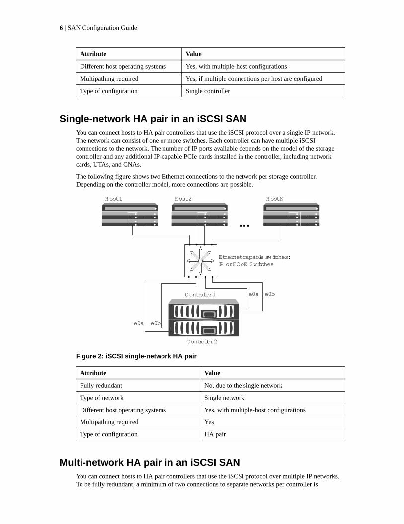
Single-network HA pair in an iSCSI SANYou can connect hosts to HA pair controllers that use the iSCSI protocol over a single IP network.The network can consist of one or more switches. Each controller can have multiple iSCSIconnections to the network. The number of IP ports available depends on the model of the storagecontroller and any additional IP-capable PCIe cards installed in the controller, including networkcards, UTAs, and CNAs.
The following figure shows two Ethernet connections to the network per storage controller.Depending on the controller model, more connections are possible.
Host 1 Host 2 Host N
Controller 1
Controller 2
Ethernet capable switches: IP or FCoE Switches
e0a
e0a
e0b
e0b
Figure 2: iSCSI single-network HA pair
Attribute Value
Fully redundant No, due to the single network
Type of network Single network
Different host operating systems Yes, with multiple-host configurations
Multipathing required Yes
Type of configuration HA pair
Multi-network HA pair in an iSCSI SANYou can connect hosts to HA pair controllers that use the iSCSI protocol over multiple IP networks.To be fully redundant, a minimum of two connections to separate networks per controller is
6 | SAN Configuration Guide

necessary to protect against NIC, network, and cabling failure. The host requires multipathingsoftware to be installed and configured.
Host 1 Host 2 Host N
Controller 1
Ethernet capable switches: IP or FCoE Switches
Ethernet capable switches: IP or FCoE Switches
e0a e0be0a
e0b
Controller 2
Figure 3: iSCSI multi-network
Attribute Value
Fully redundant Yes
Type of network Multi-network
Different host operating systems Yes, with multiple-host configurations
Multipathing required Yes
Type of configuration HA pair
Direct-attached single-controller configurations in an iSCSISAN
You can connect hosts using iSCSI directly to controllers. The number of hosts that can be directlyconnected to a controller or pair of controllers depends on the number of available Ethernet ports.
Direct-attached configurations are not supported in HA pairs.
iSCSI configurations | 7

Figure 4: iSCSI direct-attached single-controller configurations
Attribute Value
Fully redundant No, due to the single controller
Type of network None, direct-attached
Different host operating systems Yes, with multiple-host configurations
Multipathing required Yes, if multiple connections per host are configured
Type of configuration Single controller
VLANs for iSCSI configurationsA VLAN consists of a group of switch ports grouped together into a broadcast domain. A VLAN canbe on a single switch or it can span multiple switch chassis. Static and dynamic VLANs enable youto increase security, isolate problems, and limit available paths within your IP network infrastructure.
Reasons for implementing VLANs
When you implement VLANs in large IP network infrastructures, you derive the following benefits:
• Increased security. VLANs enable you to leverage existing infrastructure while still providingenhanced security because they limit access between different nodes of an Ethernet network or anIP SAN.
• Improved Ethernet network and IP SAN reliability by isolating problems.
• Reduction of problem resolution time by limiting the problem space.
• Reduction of the number of available paths to a particular iSCSI target port.
• Reduction of the maximum number of paths used by a host. Having too many paths slowsreconnect times. If a host does not have a multipathing solution, you can use VLANs to allowonly one path.
8 | SAN Configuration Guide

Static VLANs
Static VLANs are port-based. The switch and switch port are used to define the VLAN and itsmembers.
Static VLANs offer improved security because it is not possible to breach VLANs using mediaaccess control (MAC) spoofing. However, if someone has physical access to the switch, replacing acable and reconfiguring the network address can allow access.
In some environments, it is easier to create and manage static VLANs than dynamic VLANs. This isbecause static VLANs require only the switch and port identifier to be specified, instead of the 48-bitMAC address. In addition, you can label switch port ranges with the VLAN identifier.
Dynamic VLANs
Dynamic VLANs are MAC address-based. You can define a VLAN by specifying the MAC addressof the members you want to include.
Dynamic VLANs provide flexibility and do not require mapping to the physical ports where thedevice is physically connected to the switch. You can move a cable from one port to another withoutreconfiguring the VLAN.
iSCSI configurations | 9

Fibre Channel configurations
Supported FC configurations include single-fabric, multifabric, and direct-attached configurations.Both single-controller and HA pairs are supported.
For multiple-host configurations, hosts can use different operating systems, such as Windows orUNIX. Hosts require that a supported multipathing solution be installed and configured.
HA pairs with multiple, physically independent storage fabrics (minimum of two) are recommendedfor SAN solutions. This provides redundancy at the fabric and storage system layers. Redundancy isparticularly important because these layers typically support many hosts.
The use of heterogeneous FC switch fabrics is not supported, except in the case of embedded bladeswitches. For specific exceptions, see the Interoperability Matrix on the NetApp Support Site.
Cascade, mesh, and core-edge fabrics are all industry-standard methods of connecting FC switches toa fabric, and all are supported.
A fabric can consist of one or multiple switches, and the storage controllers can be connected tomultiple switches.
Related information
NetApp Interoperability Matrix: support.netapp.com/NOW/products/interoperability/
Recommended number of paths to avoid single points offailure
You should have a minimum of two paths per LUN connecting to each controller in your storagesolution. This eliminates single points of failure and enables the system to survive componentfailures.
FC supported hop countsThe maximum supported FC hop count between a host and storage system depends on the switchsupplier and storage system support for FC configurations.
The hop count is defined as the number of switches in the path between the initiator (host) and target(storage system). Cisco also refers to this value as the diameter of the SAN fabric.
The following table lists supported hop counts:
Switch supplier Supported hop count
Brocade 7 for FC
5 for FCoE
Cisco 7
Up to 3 of the switches can be FCoE switches.
10
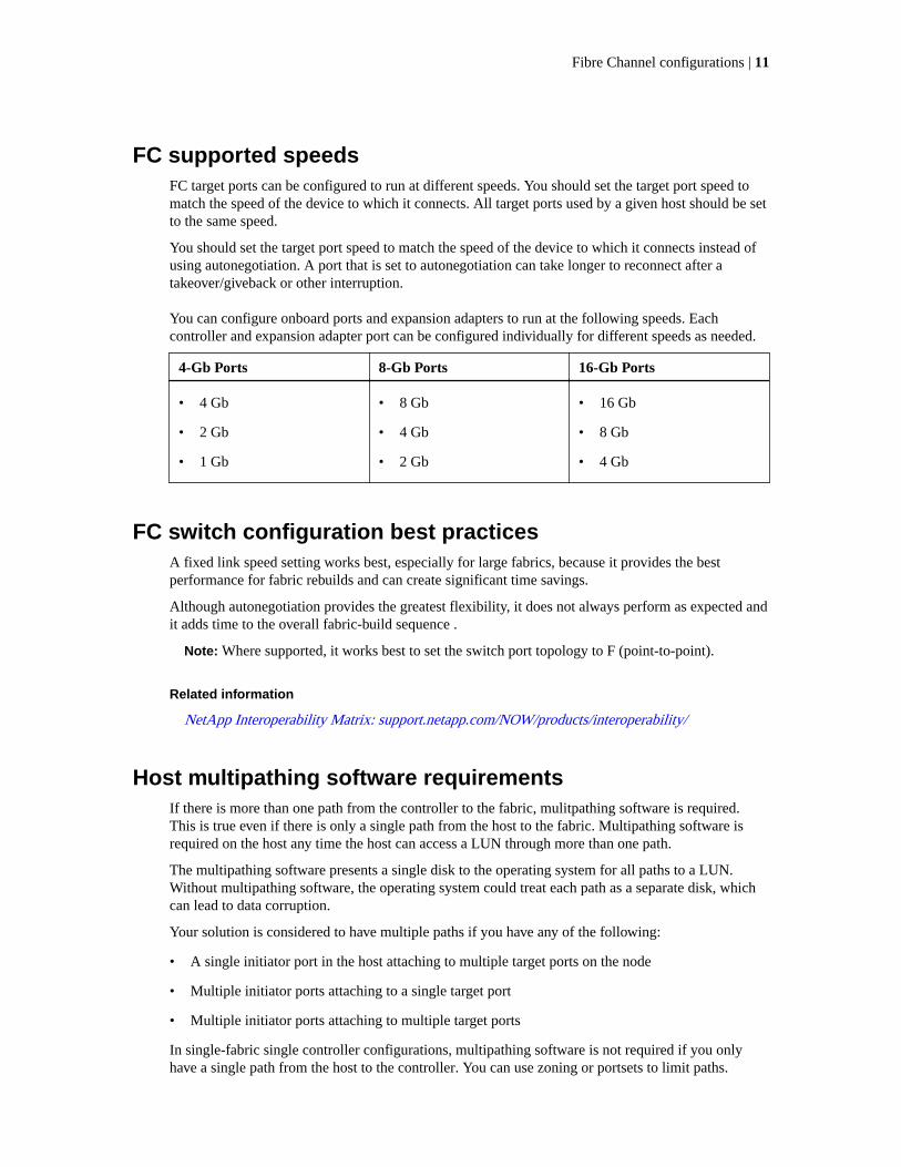
FC supported speedsFC target ports can be configured to run at different speeds. You should set the target port speed tomatch the speed of the device to which it connects. All target ports used by a given host should be setto the same speed.
You should set the target port speed to match the speed of the device to which it connects instead ofusing autonegotiation. A port that is set to autonegotiation can take longer to reconnect after atakeover/giveback or other interruption.
You can configure onboard ports and expansion adapters to run at the following speeds. Eachcontroller and expansion adapter port can be configured individually for different speeds as needed.
4-Gb Ports 8-Gb Ports 16-Gb Ports
• 4 Gb
• 2 Gb
• 1 Gb
• 8 Gb
• 4 Gb
• 2 Gb
• 16 Gb
• 8 Gb
• 4 Gb
FC switch configuration best practicesA fixed link speed setting works best, especially for large fabrics, because it provides the bestperformance for fabric rebuilds and can create significant time savings.
Although autonegotiation provides the greatest flexibility, it does not always perform as expected andit adds time to the overall fabric-build sequence .
Note: Where supported, it works best to set the switch port topology to F (point-to-point).
Related information
NetApp Interoperability Matrix: support.netapp.com/NOW/products/interoperability/
Host multipathing software requirementsIf there is more than one path from the controller to the fabric, mulitpathing software is required.This is true even if there is only a single path from the host to the fabric. Multipathing software isrequired on the host any time the host can access a LUN through more than one path.
The multipathing software presents a single disk to the operating system for all paths to a LUN.Without multipathing software, the operating system could treat each path as a separate disk, whichcan lead to data corruption.
Your solution is considered to have multiple paths if you have any of the following:
• A single initiator port in the host attaching to multiple target ports on the node
• Multiple initiator ports attaching to a single target port
• Multiple initiator ports attaching to multiple target ports
In single-fabric single controller configurations, multipathing software is not required if you onlyhave a single path from the host to the controller. You can use zoning or portsets to limit paths.
Fibre Channel configurations | 11
In HA configurations, multipathing software is required unless you use zoning or portsets to limit thehost a single path.
Multipathing software is also known as MPIO (multipath I/O) software. For information aboutoperating system support for multipathing software, see the Interoperability Matrix.
Related information
NetApp Interoperability Matrix: support.netapp.com/NOW/products/interoperability/
Supported FC portsThe number of onboard FC ports varies based on the model of the controller. FC ports are alsoavailable through supported target expansion adapters.
Onboard FC ports:
• Onboard ports can be individually configured as either target or initiator FC ports.
• The number of onboard FC ports differs depending on controller model.
A complete list of onboard FC ports on each controller model is available from the HardwareUniverse.
• FC ports are only available on the FAS2240 through the X1150A-R6 expansion adapter.
The FAS2220 and FAS2520 do not support FC.
Target expansion adapter FC ports:
• Available target expansion adapters differ depending on controller model.
A complete list of target expansion adapters for each controller model is available from theHardware Universe.
• Except for the expansion adapter models listed in the table, the ports on FC expansion adaptersare configured as initiators or targets at the factory and cannot be changed.
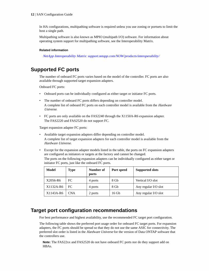
The ports on the following expansion adapters can be individually configured as either target orinitiator FC ports, just like the onboard FC ports.
Model Type Number ofports
Port speed Supported slots
X2056-R6 FC 4 ports 8 Gb Vertical I/O slot
X1132A-R6 FC 4 ports 8 Gb Any regular I/O slot
X1143A-R6 CNA 2 ports 16 Gb Any regular I/O slot
Target port configuration recommendationsFor best performance and highest availability, use the recommended FC target port configuration.
The following table shows the preferred port usage order for onboard FC target ports. For expansionadapters, the FC ports should be spread so that they do not use the same ASIC for connectivity. Thepreferred slot order is listed in the Hardware Universe for the version of Data ONTAP software thatthe controllers use.
Note: The FAS22xx and FAS2520 do not have onboard FC ports nor do they support add onHBAs.
12 | SAN Configuration Guide

Controller Port pairswith sharedASIC
Number of target ports: Preferred ports
FAS8060 andFAS8040
0e+0f
0g+0h
1: 0e
2: 0e, 0g
3: 0e, 0g, 0h
4: 0e, 0g, 0f, 0h
FAS8020 0c+0d 1: 0c
2: 0c, 0d
62xx 0a+0b
0c+0d
1: 0a
2: 0a, 0c
3: 0a, 0c, 0b
4: 0a, 0c, 0b, 0d
6080 and 6040 0a+0b
0c+0d
0e+0f
0g+0h
1: 0h
2: 0h, 0d
3: 0h, 0d, 0f
4: 0h, 0d, 0f, 0b
5: 0h, 0d, 0f, 0b, 0g
6: 0h, 0d, 0f, 0b, 0g, 0c
7: 0h, 0d, 0f, 0b, 0g, 0c, 0e
8: 0h, 0d, 0f, 0b, 0g, 0c, 0e, 0a
32xx 0c+0d 1: 0c
2: 0c, 0d
31xx 0a+0b
0c+0d
1: 0d
2: 0d, 0b
3: 0d, 0b, 0c
4: 0d, 0b, 0c, 0a
FAS2554 andFAS2552
0c+0d
0e+0f
1: 0c
2: 0c, 0e
3: 0c, 0e, 0d
4: 0c, 0e, 0d, 0f
Single-controller configurationsYou can connect hosts to single controllers using a single FC fabric or using multiple FC fabrics.Single-controller configurations support different host operating systems with multiple-hostconfigurations. Single controller configurations do not provide redundancy.
In single-controller configurations, you can use the maximum number of supported onboard FC portsper controller and the maximum number of supported target expansion adapters. For the FAS2240,both ports on the supported 2-port 8-Gb FC expansion adapter must be configured as targets on eachcontroller. For more information about the number of onboard ports and target expansion adapterssupported by your specific platform, see the Hardware Universe.
If you use multiple paths, multipathing software is required on the host. FC switch zoning or portsetsare recommended to limit the number of paths between hosts and LUNs in configurations withmultiple target ports connected to the same fabric.
Fibre Channel configurations | 13

The following illustration shows a single-fabric, single-controller configuration. The FC target portnumbers (0c, 0d) are examples. The actual port numbers vary, depending on the model of yourstorage controller and whether you are using onboard ports or FC target expansion adapters. If youare using FC target expansion adapters, the target port numbers also depend on the expansion slotsinto which your target expansion adapters are installed.
Host 1 Host 2 Host N
Controller 1
Single Switch/Fabric 1
0c 0d
The following illustration shows a multifabric, single-controller configuration. The FC target portnumbers (0c, 1a, 0d, 1b) are examples. The actual port numbers vary, depending on the model ofyour storage controller and whether you are using onboard ports or FC target expansion adapters. Ifyou are using FC target expansion adapters, the target port numbers also depend on the expansionslots into which your target expansion adapters are installed.
Host 1 Host 2 Host N
Controller
Switch/Fabric 1 Switch/Fabric 2
0c 1a 0d 1b
Direct-attached single controller configurationsYou can connect hosts directly to FC target ports on a single controller. Because there is only onecontroller, direct-attached single controller configurations are not fully redundant. Direct-attachedsingle controller configurations support different host operating systems with multiple-hostconfigurations.
In direct-attached configurations, you can use the maximum number of supported onboard FC portsper controller and the maximum number of supported target expansion adapters. The number of hosts
14 | SAN Configuration Guide

is limited by the number of available target ports. For more information about the number of onboardports and target expansion adapters supported by your specific platform, see the Hardware Universe.
If you use multiple paths to a LUN, multipathing software is required on the host.
Direct-attached configurations typically need the FC ports set to auto mode, but you must follow therecommendation of your host operating system provider for FC port settings. The fcp configmediatype command sets the target ports; see the fcp man page for more information about thatcommand.
The following illustration shows various methods for implementing direct-attached single controllerconfigurations:
Host 1
Host 1
Host 2
Host 3 Host 1 Host 2Host N
Controller 1 Controller 1 Controller 1
Direct-attached HA configurationsYou can connect hosts directly to FC target ports on both controllers in an HA configuration.Multifabric HA configurations are fully redundant and support different host operating systems withmultiple-host configurations. The number of hosts is limited by the number of available target ports.
In direct-attached HA configurations, you can use the maximum number of supported onboard FCports per controller and the maximum number of supported target expansion adapters. For theFAS2240, both ports on the supported 2-port 8-Gb FC expansion adapter must be configured astargets on each controller. For more information about the number of onboard ports and targetexpansion adapters supported by your specific platform, see the Hardware Universe.
If you use multiple paths to a LUN, multipathing software is required on the host.
Direct-attached configurations typically need the FC ports set to auto mode, but you must follow therecommendation of your host operating system provider for FC port settings. The fcp configmediatype command sets the target ports; see the fcp man page for more information about thatcommand.
The FC target port numbers in the following figure (0c, 0c) are examples. The actual port numbersvary, depending on the model of your storage controller and whether you are using onboard ports orFC target expansion adapters. If you are using FC target expansion adapters, the target port numbersalso depend on the expansion slots into which your target expansion adapters are installed.
Fibre Channel configurations | 15
Host
Controller 1
Controller 2
0c0c
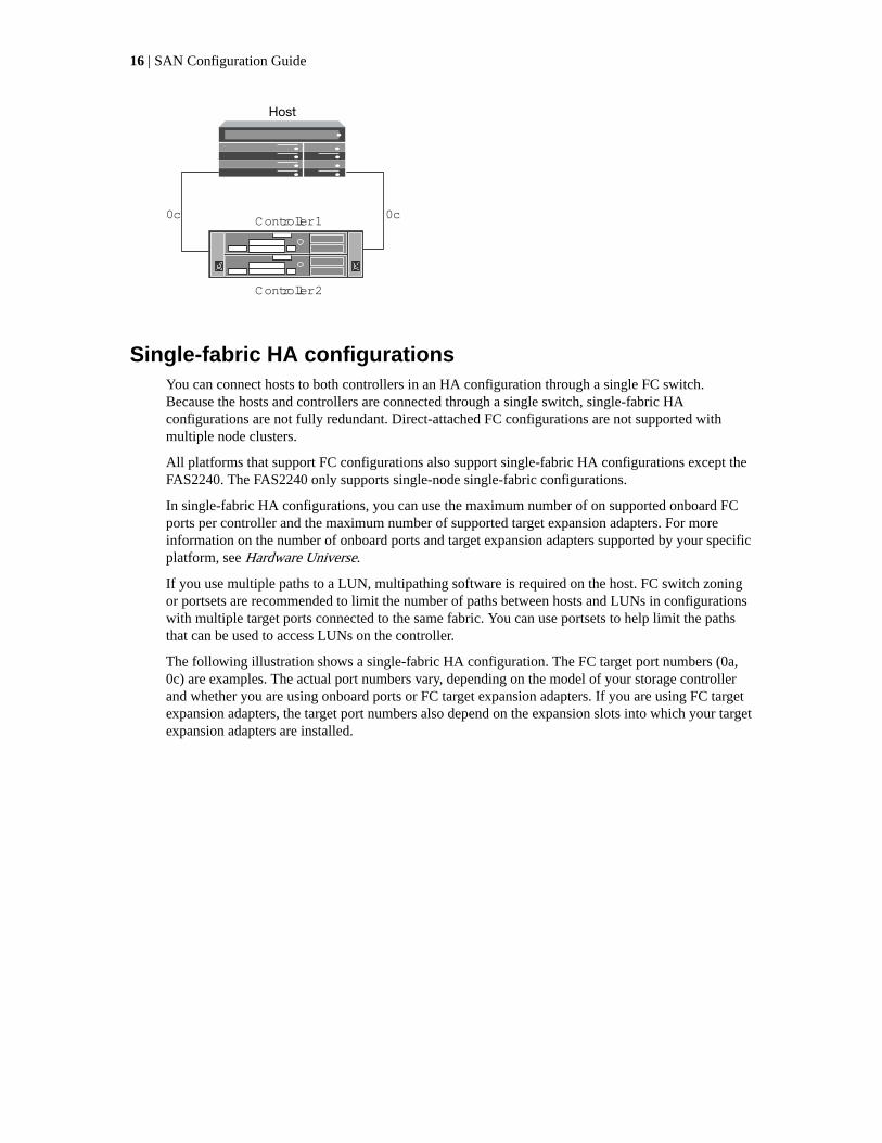
Single-fabric HA configurationsYou can connect hosts to both controllers in an HA configuration through a single FC switch.Because the hosts and controllers are connected through a single switch, single-fabric HAconfigurations are not fully redundant. Direct-attached FC configurations are not supported withmultiple node clusters.
All platforms that support FC configurations also support single-fabric HA configurations except theFAS2240. The FAS2240 only supports single-node single-fabric configurations.
In single-fabric HA configurations, you can use the maximum number of on supported onboard FCports per controller and the maximum number of supported target expansion adapters. For moreinformation on the number of onboard ports and target expansion adapters supported by your specificplatform, see Hardware Universe.
If you use multiple paths to a LUN, multipathing software is required on the host. FC switch zoningor portsets are recommended to limit the number of paths between hosts and LUNs in configurationswith multiple target ports connected to the same fabric. You can use portsets to help limit the pathsthat can be used to access LUNs on the controller.
The following illustration shows a single-fabric HA configuration. The FC target port numbers (0a,0c) are examples. The actual port numbers vary, depending on the model of your storage controllerand whether you are using onboard ports or FC target expansion adapters. If you are using FC targetexpansion adapters, the target port numbers also depend on the expansion slots into which your targetexpansion adapters are installed.
16 | SAN Configuration Guide

Host 1 Host 2 Host N
Controller 1
Controller 2
Single Switch/Fabric
0a 0c0a 0c
Related references
Single-fabric zoning on page 24
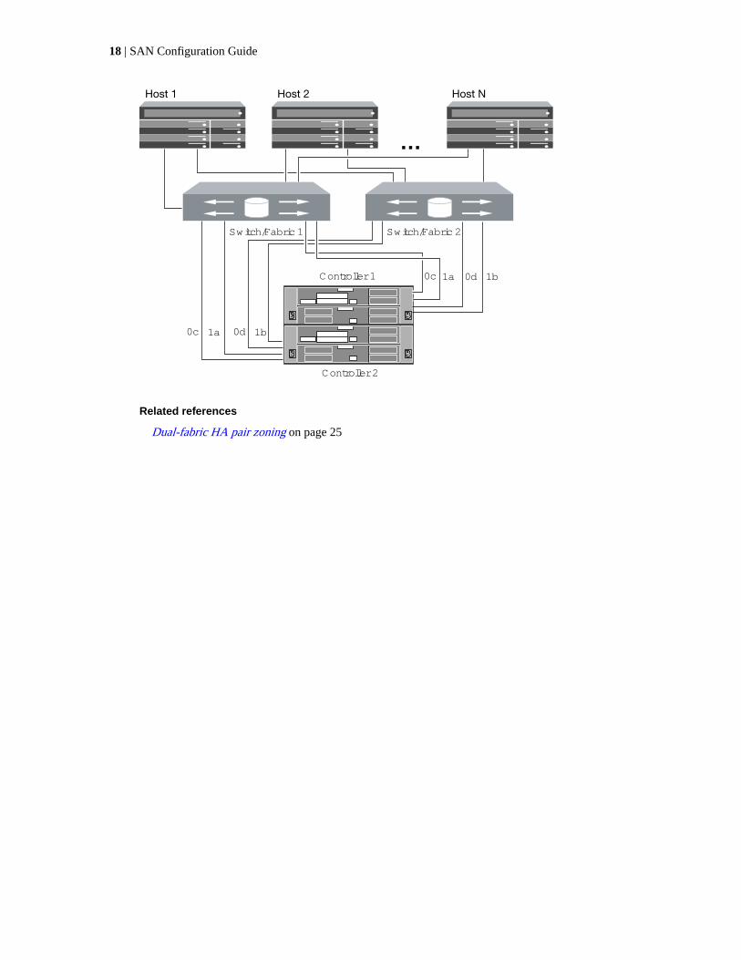
Multifabric HA configurationsYou can connect hosts to both controllers in an HA configuration through two or more FC switchfabrics. Multifabric HA configurations are fully redundant and support different host operatingsystems with multiple-host configurations.
All platforms that support FC configurations also support multifabric HA configurations, except theFAS2240. The FAS2240 supports only single-node, single-fabric configurations.
In multifabric HA configurations, you can use the maximum number of supported onboard FC portsper controller and the maximum number of supported target expansion adapters. For moreinformation on the number of onboard ports and target expansion adapters supported by your specificplatform, see the Hardware Universe.
If you use multiple paths to a LUN, multipathing software is required on the host. FC switch zoningor portsets are recommended, to limit the number of paths between hosts and LUNs in configurationswith multiple target ports connected to the same fabric. You can use portsets to help limit the pathsthat can be used to access LUNs on the controller
For simplicity, the following multifabric HA illustration shows only two fabrics. However, you canhave two or more fabrics in any multifabric configuration. The FC target port numbers (0c, 1a, 0d,1bd) are examples. The actual port numbers vary, depending on the model of your storage controllerand whether you are using onboard ports or FC target expansion adapters. If you are using FC targetexpansion adapters, the target port numbers also depend on the expansion slots into which your targetexpansion adapters are installed.
Fibre Channel configurations | 17
Host 1 Host 2 Host N
Controller 1
Controller 2
Switch/Fabric 1 Switch/Fabric 2
0c 1a 0d 1b
0d 1b0c 1a
Related references
Dual-fabric HA pair zoning on page 25
18 | SAN Configuration Guide
Fibre Channel over Ethernet overview
Fibre Channel over Ethernet (FCoE) is a model for connecting hosts to storage systems. As withFibre Channel (FC), FCoE maintains existing FC management and controls. However, the hardwaretransport is a lossless 10-Gb Ethernet network.
Setting up an FCoE connection on the host or storage requires one or more supported convergednetwork adapters (CNAs) connected to a supported FCoE switch. The CNA is a consolidation pointand effectively serves as both an FC HBA and an Ethernet adapter.
The CNA is presented to the host and target as both an FCoE Initiator HBA and a 10-Gb Ethernetadapter. The FCoE Initiator HBA portion of the CNA handles the FCoE traffic when traffic is sentand received as FC frames mapped into Ethernet packets (FC over Ethernet). The Ethernet adapterportion of the CNA handles the standard Ethernet IP traffic, such as iSCSI, CIFS, NFS, and HTTP,for the host. Both the FCoE and standard Ethernet portions of the CNA communicate over the sameEthernet port, which connects to the FCoE switch.
The FCoE target adapter is also sometimes called a "unified target adapter" or UTA. Like the CNA,the UTA supports both FCoE and regular Ethernet traffic.
You should configure jumbo frames (MTU = 9000) for the Ethernet adapter portion of the CNA. Youcannot change the MTU for the FCoE portion of the adapter.
Note: Unified target adapters (UTAs) are 10-Gb converged network adapters (CNAs) that youinstall in your storage systems.
In general, you configure and use FCoE connections just like traditional FC connections. You can useUTAs for non-FCoE IP traffic such as NFS, CIFS, or iSCSI.
Note: For detailed information about how to set up and configure your host to run FCoE, see yourhost documentation.
Recommended number of paths to avoid single points offailure
You should have a minimum of two paths per LUN connecting to each controller in your storagesolution. This eliminates single points of failure and enables the system to survive componentfailures.
FCoE initiator and target combinationsCertain combinations of FCoE and traditional FC initiators and targets are supported.
FCoE initiators
You can use FCoE initiators in host computers with both FCoE and traditional FC targets in storagecontrollers. The host FCoE initiator must connect to an FCoE DCB (data center bridging) switch;direct connection to a target is not supported.
The following table lists the supported combinations:
Initiator Target Supported?
FC FC Yes
FC FCoE Yes
19
Initiator Target Supported?
FCoE FC Yes
FCoE FCoE Yes
FCoE targets
You can mix FCoE target ports with 4-Gb, 8-Gb, or 16-Gb FC ports on the storage controllerregardless of whether the FC ports are add-in target adapters or onboard ports. You can have bothFCoE and FC target adapters in the same storage controller.
Note: The rules for combining onboard and expansion FC ports still apply.
FCoE supported hop countThe maximum supported Fibre Channel over Ethernet (FCoE) hop count between a host and storagesystem depends on the switch supplier and storage system support for FCoE configurations.
The hop count is defined as the number of switches in the path between the initiator (host) and target(storage system). Documentation from Cisco Systems also refers to this value as the diameter of theSAN fabric.
For FCoE, you can have FCoE switches connected to FC switches.
For end-to-end FCoE connections, the FCoE switches must be running a firmware version thatsupports Ethernet inter-switch links (ISLs).
The following table lists the maximum supported hop counts:
Switch supplier Supported hop count
Brocade 7 for FC
5 for FCoE
Cisco 7
Up to 3 of the switches can be FCoE switches.
FCoE supported configurationsAll storage systems are supported with native Fibre Channel over Ethernet (FCoE) target expansionadapters (called unified target adapters or UTAs), in single-fabric and multi-fabric configurations,except the FAS22xx and FAS2520. The FAS22xx and FAS2520 does not support FCoE.
Both single-controller and HA configurations are supported.
The host FCoE initiator with FC target configuration is also supported on all storage systems usingan FCoE/DCB switch. Direct-attached configurations are not supported in FCoE using UTAs for FCor iSCSI.
Note: Although iSCSI configurations are supported on standard Ethernet switches and have thesame supportability requirements as other IP-based protocols, FCoE configurations requireEthernet switches that explicitly support FCoE features. If a CNA is used as a 10-Gb Ethernet cardand only IP protocols are going to be used, then a switch that supports FCoE for connectivity is notrequired.
FCoE configurations are validated through the same interoperability and quality assurance processas FC switches. Supported configurations are listed in the Interoperability Matrix. Some of the
20 | SAN Configuration Guide

parameters included in these supported configurations are the switch model, the number ofswitches that can be deployed in a single fabric, and the supported switch firmware version.
Related information
NetApp Interoperability Matrix: support.netapp.com/NOW/products/interoperability/
FCoE initiator to FC target configuration
You can connect hosts to both controllers in an HA pair using host FCoE initiators (CNAs) throughFCoE switches to FC target ports. This requires an FCoE switch that also has FC ports.
The host FCoE initiator always connects to a supported FCoE switch. The FCoE switch can connectdirectly to an FC target, or can connect through FC switches to the FC target.
Note: The following illustration shows a FCoE initiator to FC dual-fabric HA configuration. TheFC target expansion adapter port numbers (0b and 0d) are examples. The actual port numbers vary,depending on the expansion slot in which the FC target expansion adapter is installed.
Host 1
CNA Ports CNA Ports CNA Ports
Switch 1/Fabric 1
Controller 1
Controller 2
0d0b
0d0b
Switch 2/Fabric 2
Host 2 Host N
FCoE Switch
IP NetworkIP Network
FCoE Switch
DCBPorts
DCBPorts
FC Ports FC Ports
Attribute Value
Fully redundant Yes
Type of fabric Dual fabric
Different host operating systems Yes, with multiple-host configurations
FC ports or adapters One to the maximum number of supported onboard FC portsper controller
One to the maximum number of supported 4-Gb, 8-Gb, or 16-Gb FC ports per controller using FC target expansion adapters
Multipathing required Yes
Fibre Channel over Ethernet overview | 21
Attribute Value
Type of configuration HA pair
22 | SAN Configuration Guide
Fibre Channel and FCoE zoning
An FC or FCoE zone is a subset of the fabric that consists of a group of FC or FCoE ports or nodesthat can communicate with each other. You must contain the nodes within the same zone to allowcommunication.
Reasons for zoning
• Zoning reduces or eliminates cross talk between initiator HBAs. This occurs even in smallenvironments and is one of the best arguments for implementing zoning. The logical fabricsubsets created by zoning eliminate crosstalk problems.
• Zoning reduces the number of available paths to a particular FC or FCoE port and reduces thenumber of paths between a host and a particular LUN that is visible. For example, some host OSmultipathing solutions have a limit on the number of paths they can manage. Zoning can reducethe number of paths that an OS multipathing driver sees. If a host does not have a multipathingsolution installed, you need to verify that only one path to a LUN is visible.
• Zoning increases security because there is limited access between different nodes of a SAN.
• Zoning improves SAN reliability by isolating problems that occur and helps to reduce problemresolution time by limiting the problem space.
Recommendations for zoning
• You should implement zoning anytime four or more hosts are connected to a SAN.
• Although World Wide Node Name zoning is possible with some switch vendors, World Wide PortName zoning is recommended.
• You should limit the zone size while still maintaining manageability. Multiple zones can overlapto limit size. Ideally, a zone is defined for each host or host cluster.
• You should use single-initiator zoning to eliminate crosstalk between initiator HBAs.
Port zoningPort zoning, also referred to as “hard zoning,” specifies the unique fabric N_port IDs of the ports tobe included within the zone. The switch and switch port are used to define the zone members.
Port zoning provides the following advantages:
• Port zoning offers improved security because it is not possible to breach the zoning by usingWWPN spoofing. However, if someone has physical access to the switch, replacing a cable canallow access.
• In some environments, port zoning is easier to create and manage because you only work with theswitch or switch domain and port number.
23

World Wide Name-based zoningZoning based on World Wide Name (WWN) specifies the WWN of the members to be includedwithin the zone. Depending on the switch vendor, either World Wide Node Names or World WidePort Names can be used. You should always use World Wide Port Name zoning.
WWPN zoning provides flexibility because access is not determined by where the device isphysically connected to the fabric. You can move a cable from one port to another withoutreconfiguring zones.
Individual zonesIn the recommended zoning configuration, there is one host initiator per zone. The zone consists ofthe host initiator port and one or more target ports on each storage controller up to the desirednumber of paths per target. This means that hosts accessing the same controllers cannot see eachother's ports, but each initiator can access both controllers.
Single-fabric zoningIn a single-fabric configuration, you can still connect each host initiator to each storage controller.Multipathing software is required on the host to manage multiple paths. Each host should have twoinitiators for multipathing to provide resiliency in the solution.
Each initiator can access a target port on both storage controllers in an HA configuration, but shouldonly be zoned to the storage controllers that are providing the paths used for connectivity. This meansthat each initiator on the host might only have one target port per storage controller in its zoneconfiguration. If there is a requirement for multipathing to the same storage controller, then eachstorage controller will have multiple ports per initiator in its zone configuration. This enables the hostto still access its LUNs if a controller fails.
Single-fabric configurations are supported, but are not considered highly available. The failure of asingle component can cause loss of access to data.
In the following figure, the host has two initiators and is running multipathing software. There aretwo zones:
• Zone 1: HBA 0, port 0b on Controller 1, and port 0b on Controller 2
• Zone 2: HBA 1, port 0d on Controller 1, and port 0d on Controller 2
24 | SAN Configuration Guide

Host
Switch
Controller 1 Controller 2
HBA 0 HBA 1
0b0d
0b 0d
Figure 5: Single-fabric zoning
In this example, you could also have all four ports in each zone. In that case, the zones would be:
• Zone 1: HBA 0, ports 0b and 0d on Controller 1, and ports 0b and 0d on Controller 2
• Zone 2: HBA 1, ports 0b and 0d on Controller 1, and ports 0b and 0d on Controller 2
Note: The host operating system and multipathing software have to support the number ofsupported paths that are being used to access the LUNs on the storage controllers. To determinethe number of paths used to access the LUNs on [nodes or storage controllers], see theconfiguration limits information elsewhere in this document.
Dual-fabric HA pair zoningIn dual fabric configurations, you can connect each host initiator to each storage controller. Each hostinitiator uses a different switch to access the storage controllers. Multipathing software is required onthe host to manage multiple paths.
Dual fabric configurations are considered high availability because access to data is maintained in theevent of a single component failure.
In the following figure, the host has two initiators and is running multipathing software. There aretwo zones:
• Zone 1: HBA 0, port 0b on Controller 1, and port 0b on Controller 2
• Zone 2: HBA 1, port 0d on Controller 1, and port 0d on Controller 2
Each host initiator is zoned through a different switch. Zone 1 is accessed through Switch 1. Zone 2is accessed through Switch 2.
Because each host initiator is zoned to a port on each controller, the host can still access its LUNs if acontroller fails.
Fibre Channel and FCoE zoning | 25

Host
Switch 1 Switch 2
Controller 1 Controller 2
HBA 0 HBA 1
0b 0d 0b 0d
Figure 6: Dual-fabric zoning
In this example, you could also have all four ports in each zone. In that case, the zones would be:
• Zone 1: HBA 0, ports 0b and 0d on Controller 1, and ports 0b and 0d on Controller 2
• Zone 2: HBA 1, ports 0b and 0d on Controller 1, and ports 0b and 0d on Controller 2
Note: The host operating system and multipathing software have to support the number of pathsthat is being used to access the LUNs on the storage controllers. Information on supported pathand LUN limitations can be verified by using the configuration limits at the end of this document.
26 | SAN Configuration Guide

Shared SAN configurations
Shared SAN configurations are defined as hosts that are attached to both Data ONTAP and non-DataONTAP storage systems. Accessing Data ONTAP storage systems and other vendors' storagesystems from a single host is supported as long as several requirements are met.
Accessing Data ONTAP storage systems and other vendors' storage systems from a single hostrequires:
• Native Host OS multipathing or VERITAS DMP is used for multipathing (see exception for EMCPowerPath co-existence below)
• NetApp configuration requirements (such as timeout settings) as specified in the appropriate HostUtilities documents have been met
Native Host OS multipathing in combination with EMC PowerPath is supported for the followingconfigurations. For configurations that do not meet these requirements, a PVR is required todetermine supportability.
Host Supported configuration
Windows EMC CX3, CX4, and VNX storage arrays with PowerPath 4.5 or later connected to aData ONTAP storage system using Data ONTAP DSM for Windows MPIO. Thisapplies equally to Windows 2003, Windows 2008, and Windows 2012.
Solaris EMC CX3, CX4, and VNX storage arrays PowerPath 5 or later connected to a DataONTAP storage system using MPxIO
AIX EMC CX3, CX4, and VNX storage arrays PowerPath 5 or later connected to a DataONTAP storage system using AIX MPIO
27

ALUA configurations
Asymmetric logical unit access (ALUA) is supported for certain combinations of host operatingsystems and host multipathing software.
ALUA is an industry standard protocol for identifying optimized paths between a storage system anda host computer. The administrator of the host computer does not need to manually select the paths touse.
You should use ALUA whenever the host configuration supports it. For information about whichspecific configurations support ALUA, see the Interoperability Matrix and the Host UtilitiesInstallation and Setup Guide for your host operating system.
ALUA is enabled or disabled on the igroup to which the LUN is mapped. The default ALUA settingin Data ONTAP depends on the igroup type. ALUA is not supported for iSCSI paths.
For information about enabling ALUA on the storage system, see the Data ONTAP SANAdministration Guide for 7-Mode.
Related information
NetApp Interoperability Matrix - support.netapp.com/NOW/products/interoperability/
Host Utilities documentation - support.netapp.com/documentation/productlibrary/index.html?productID=61343
28

Configuration limits for FC, FCoE, and iSCSIconfigurations
Configuration limits are available for FC, FCoE, and iSCSI configurations. In some cases, theoreticallimits might be higher, but the published limits are tested and supported.
SAN configuration limit parameters and definitionsThere are a number of parameters and definitions related to FC, FCoE, and iSCSI configurationlimits.
Parameter Definition
Visible target portsper host (iSCSI)
The maximum number of target iSCSI Ethernet ports that a host can seeor access on iSCSI-attached controllers.
Visible target portsper host (FC)
The maximum number of FC adapters that a host can see or access on theattached Fibre Channel controllers.
LUNs per host The maximum number of LUNs that you can map from the controllers toa single host.
Maximum paths fromhost to LUN
The maximum number of paths from the host to a single LUN
Note: Using the maximum number of paths is not recommended.
Maximum paths fromhost to storagesolution
The maximum total number of paths from the host to the connectedstorage solution.
Maximum LUN size The maximum size of an individual LUN on the respective operatingsystem.
LUNs per controlleror node
The maximum number of LUNs that you can configure per controller,including cloned LUNs and LUNs contained within cloned volumes.LUNs contained in Snapshot copies do not count in this limit, and there isno limit on the number of LUNs that can be contained within Snapshotcopies.
LUNs per volume The maximum number of LUNs that you can configure within a singlevolume. LUNs contained in Snapshot copies do not count in this limit, andthere is no limit on the number of LUNs that can be contained withinSnapshot copies.
FC port fan-in The maximum number of hosts that can connect to a single FC port on acontroller. Connecting the maximum number of hosts is generally notrecommended, and you might need to tune the FC queue depths on thehost to achieve this maximum value.
iSCSI sessions percontroller or node
The recommended maximum number of iSCSI sessions that you canconnect to a single controller. The general formula to calculate this is asfollows: Maximum sessions = 8 × System Memory ÷ 512 MB.
29
Parameter Definition
Hosts per controller(FC)
The maximum number of hosts that can connect to a controller.Connecting the maximum number of hosts is generally not recommended,and you might need to tune the FC queue depths on the host to achievethis maximum value. This value assumes two initiators per host.
Note: Virtualized hosts, using NPIV to access the fabric with virtualWWPNs, count as additional hosts for the purpose of this limitation.
igroups per controller The maximum number of initiator groups that you can configure percontroller.
Initiators per igroup The maximum number of FC initiators (HBA WWNs) or iSCSI initiators(host iqn/eui node names) that you can include in a single igroup.
LUN mappings percontroller
The maximum number of LUN mappings per controller. For example, aLUN mapped to two igroups counts as two mappings.
LUN path namelength
The maximum number of characters in a full LUN name. Forexample, /vol/abc/def has 12 characters.
LUN size The maximum capacity of an individual LUN on a controller.
FC queue depthavailable per port
The usable queue depth capacity of each FC target port. The number ofLUNs is limited by available FC queue depth.
FC target ports percontroller or node
The maximum number of supported FC target ports per controller. FCinitiator ports used for back-end disk connections, for example,connections to disk shelves, are not included in this number.
Related references
SAN configuration limits on page 31
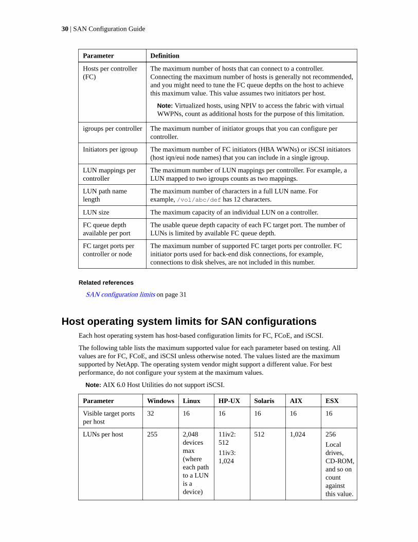
Host operating system limits for SAN configurationsEach host operating system has host-based configuration limits for FC, FCoE, and iSCSI.
The following table lists the maximum supported value for each parameter based on testing. Allvalues are for FC, FCoE, and iSCSI unless otherwise noted. The values listed are the maximumsupported by NetApp. The operating system vendor might support a different value. For bestperformance, do not configure your system at the maximum values.
Note: AIX 6.0 Host Utilities do not support iSCSI.
Parameter Windows Linux HP-UX Solaris AIX ESX
Visible target portsper host
32 16 16 16 16 16
LUNs per host 255 2,048devicesmax(whereeach pathto a LUNis adevice)
11iv2:512
11iv3:1,024
512 1,024 256
Localdrives,CD-ROM,and so oncountagainstthis value.
30 | SAN Configuration Guide

Parameter Windows Linux HP-UX Solaris AIX ESX
Maximum pathsfrom host to LUN
32 24 (maxof 2,048per host)
11iv2: 8
11iv3: 32
16 16 32
(max of1,024 perhost)
Maximum pathsfrom host to storagesolution
1,024 1,024 11iv2: 8
11iv3: 32
16 16 8
(max of1,024 perhost)
Max LUN size 2 TB(MBR)
16 TB(GPT)
16 TB 11iv2: 2TB
11iv3: 16TB
16 TB 16 TB 16 TB(VMFS-5and passthroughRDM)
2 TB(VMFS-3and non-pass-throughRDM)
SAN configuration limitsEach system model has configuration limits for reliable operation. The values listed are the maximumthat can be supported. Do not exceed the tested limits.
The following table lists the maximum supported value for each parameter based on testing. For bestperformance, do not configure your system with the maximum values. All values are for FC, FCoE,and iSCSI unless otherwise noted. If any node in the cluster is configured for FC, FCoE, or iSCSI,the cluster is limited to the SAN node limits.
The maximum number of LUNs and the number of host HBAs that can connect to an FC port arelimited by the available queue depth on the FC target ports.
Configuration limits for FC, FCoE, and iSCSI configurations | 31

Parameters Per controller Per HA pair
LUNs 1,024 for the followingmodels:
• FAS2240
• FAS2220
2,048 for all other models
1,024 for the followingmodels:
• FAS2240
• FAS2220
2,048 for the followingmodels:
• FAS2520
• FAS2552
• FAS2554
• 31xx
• 32xx
• 60xx
4,096 for all other models
LUNs per volume 1,024 for the followingmodels:
• FAS2240
• FAS2220
2,048 for all other models
1,024 for the followingmodels:
• FAS2240
• FAS2220
2,048 for all other models
LUN mappings 4,096 for the followingmodels:
• FAS2240
• FAS2220
• FAS2520
• FAS2552
• FAS2554
• 31xx
• 32xx
8,192 for all other models
4,096 for the followingmodels:
• FAS2240
• FAS2220
• FAS2520
• FAS2552
• FAS2554
• 31xx
• 32xx
8,192 for all other models
LUN path name length 255 for all models 255 for all models
LUN size 16 TB for all models 16 TB for all models
32 | SAN Configuration Guide

Parameters Per controller Per HA pair
igroups 256 for the following models:
• FAS2240
• FAS2220
• FAS2520
• FAS2552
• FAS2554
• 31xx
• FAS3220
• 3250
512 for the 3270
1,024 for all other models
256 for the following models:
• FAS2240
• FAS2220
• FAS2520
• FAS2552
• FAS2554
• 31xx
512 for the following models:
• 31xx
• 32xx
2,048 for all other models
Initiators per igroup 256 for all models 256 for all models
iSCSI sessions 128 for the following models:
• FAS2240
• FAS2220
256 for the following models:
• 31xx
• FAS3220
• 3250
512 for all other models
128 for the following models:
• FAS2240
• FAS2220
512 for the following models:
• 31xx
• 32xx
• 6040
1,024 for all other models
Ethernet ports per controller See the Hardware Universe for platform-supported limits.
Note: The following FC limits do not apply to the FAS2520 and FAS2220 platforms. TheFAS2520 and FAS2220 do not support FC.
FC queue depth available perport
2,048 for all models 2,048 for all models
FC port fan-in 64 for all models 64 for all models
Connected FC hosts 128 for the FAS2240
256 for all other models
128 for the FAS2240
256 for the following models:
• 31xx
• 32xx
• 60xx
512 for all other models
FC target ports See the Hardware Universe for platform-supported limits.
Configuration limits for FC, FCoE, and iSCSI configurations | 33

Calculating queue depthYou might need to tune your FC queue depth on the host to achieve the maximum values for hostsper controller and FC port fan-in. The maximum number of LUNs and the number of HBAs that canconnect to an FC port are limited by the available queue depth on the FC target ports.
About this task
Queue depth is the number of I/O requests (SCSI commands) that can be queued at one time on astorage controller. Each I/O request from the host's initiator HBA to the storage controller's targetadapter consumes a queue entry. Typically, a higher queue depth equates to better performance.However, if the storage controller's maximum queue depth is reached, that storage controller rejectsincoming commands by returning a QFULL response to them. If a large number of hosts areaccessing a storage controller, plan carefully to avoid QFULL conditions, which significantlydegrade system performance and can lead to errors on some systems.
In a configuration with multiple initiators (hosts), all hosts should have similar queue depths. Thisprevents hosts with small queue depths from being starved by hosts with large queue depths.
The following general recommendations can be made about "tuning" queue depths.
• For small to mid-size systems, use a HBA queue depth of 32.
• For large systems, use a HBA queue depth of 128.
• For exception cases or performance testing, use a queue depth of 256 to avoid possible queuingproblems.
• All hosts should have the queue depths set to similar values to give equal access to all hosts.
• Ensure that the storage controller target FC port queue depth is not exceeded to avoidperformance penalties or errors.
Steps
1. Count the total number of FC initiators in all the hosts that connect to one FC target port.
2. Multiply by 128.
• If the result is less than 2,048, set the queue depth for all initiators to 128.
Example
You have 15 hosts with one initiator connected to each of two target ports on the storagecontroller. 15 x 128 = 1,920. Because 1,920 is less than the total queue depth limit of 2,048, youcan set the queue depth for all your initiators to 128.
• If the result is greater than 2,048, go to step 3.
Example
You have 30 hosts with one initiator connected to each of two target ports on the storagecontroller. 30 x 128 = 3,840. Because 3,840 is greater than the total queue depth limit of 2,048,you should choose one of the options under step 3 for remediation.
3. Choose one of the following options.
• Option 1:
a. Add more FC target ports.
34 | SAN Configuration Guide

b. Redistribute your FC initiators.
c. Repeat steps 1 and 2.
Example
The desired queue depth of 3,840 exceeds the available queue depth per port. To remedy this, youcan add a two-port FC target adapter to each controller, then rezone your FC switches so that 15of your 30 hosts connect to one set of ports, and the remaining 15 hosts connect to a second set ofports. The queue depth per port is then reduced to 15 x 128 = 1,920.
• Option 2:
a. Designate each host as "large" or "small" based on its expected I/O need.
b. Multiply the number of large initiators by 128.
c. Multiply the number of small initiators by 32.
d. Add the two results together.
e. If the result is less than 2,048, set the queue depth for "large" hosts to 128 and the queuedepth for "small" hosts to 32.
f. If the result is still greater than 2,048 per port, reduce the queue depth per initiator until thetotal queue depth is less than or equal to 2,048.
Note: To estimate the queue depth needed to achieve a certain I/O per secondthroughput, use this formula.
Needed queue depth = (Number of I/O per second) x (Response time)
For example, if you need 40,000 I/O per second with a response time of 3 milliseconds,the needed queue depth = 40,000 x (.003) = 120.
Example
The desired queue depth of 3,840 exceeds the available queue depth per port. You have 10 "large"hosts that have high storage I/O needs, and 20 "small" hosts that have low I/O needs. Set theinitiator queue depth on the "large" hosts to 128 and the initiator queue depth on the "small" hoststo 32.
Your resulting total queue depth is (10 x 128) + (20 x 32) = 1,920.
Example
You can spread the available queue depth equally across each initiator.
Your resulting queue depth per initiator is 2,048/30 = 68
Setting queue depths on AIX hosts
You can change the queue depth on AIX hosts using the chdev command. Changes made using thechdev command persist across reboots.
Examples:
• To change the queue depth for the hdisk7 device, use the following command:
chdev -l hdisk7 -a queue_depth=32
• To change the queue depth for the fcs0 HBA, use the following command:
chdev -l fcs0 -a num_cmd_elems=128
The default value for num_cmd_elems is 200. The maximum value is 2,048.
Configuration limits for FC, FCoE, and iSCSI configurations | 35

Note: It might be necessary to take the HBA offline to change num_cmd_elems and then bringit back online using the rmdev -l fcs0 -R and makdev -l fcs0 -P commands.
Setting queue depths on HP-UX hosts
You can change the LUN or device queue depth on HP-UX hosts using the kernel parameterscsi_max_qdepth. You can change the HBA queue depth using the kernel parametermax_fcp_reqs.
• The default value for scsi_max_qdepth is 8. The maximum value is 255.
scsi_max_qdepth can be dynamically changed on a running system using the -u option on thekmtune command. The change will be effective for all devices on the system. For example, usethe following command to increase the LUN queue depth to 64:
kmtune -u -s scsi_max_qdepth=64
It is possible to change queue depth for individual device files using the scsictl command.Changes using the scsictl command are not persistent across system reboots. To view andchange the queue depth for a particular device file, execute the following command:
scsictl -a /dev/rdsk/c2t2d0
scsictl -m queue_depth=16 /dev/rdsk/c2t2d0
• The default value for max_fcp_reqs is 512. The maximum value is 1024.
The kernel must be rebuilt and the system must be rebooted for changes to max_fcp_reqs totake effect. To change the HBA queue depth to 256, for example, use the following command:
kmtune -u -s max_fcp_reqs=256
Setting queue depths on Solaris hosts
You can set the LUN and HBA queue depth for your Solaris hosts.
About this task
• For LUN queue depth: The number of LUNs in use on a host multiplied by the per-LUN throttle(lun-queue-depth) must be less than or equal to the tgt-queue-depth value on the host.
• For queue depth in a Sun stack: The native drivers do not allow for per LUN or per targetmax_throttle settings at the HBA level. The recommended method for setting themax_throttle value for native drivers is on a per-device type (VID_PID) level in the /kernel/drv/sd.conf and /kernel/drv/ssd.conf files. The host utility sets this value to 64for MPxIO configurations and 8 for Veritas DMP configurations.
Steps
1. # cd/kernel/drv
2. # vi lpfc.conf
3. Search for /tft-queue (/tgt-queue)
tgt-queue-depth=32
Note: The default value is set to 32 at installation.
4. Set the desired value based on the configuration of your environment.
5. Save the file.
6. Reboot the host using the sync; sync; sync; reboot -- -r command.
36 | SAN Configuration Guide

Setting queue depths on VMware hosts
Use the esxcfg-module command to change the HBA timeout settings. Manually updating theesx.conf file is not recommended.
To set maximum queue depth for a QLogic HBA
Steps
1. Log on to the service console as the root user.
2. Use the #vmkload_mod -l command to verify which Qlogic HBA module is currently loaded.
3. For a single instance of a Qlogic HBA, run the following command:
#esxcfg-module -s ql2xmaxqdepth=64 qla2300_707
Note: This example uses qla2300_707 module. Use the appropriate module based on the outputof vmkload_mod -l.
4. Save your changes using the following command:
#/usr/sbin/esxcfg-boot -b
5. Reboot the server using the following command:
#reboot
6. Confirm the changes using the following commands:
a. #esxcfg-module -g qla2300_707
b. qla2300_707 enabled = 1 options = 'ql2xmaxqdepth=64'
To change the queue depth of an Emulex HBA
Steps
1. Log on to the service console as the root user.
2. Use the #vmkload_mod -l grep lpfcdd command to verify which Emulex HBA is currentlyloaded.
3. For a single instance of an Emulex HBA, enter the following command:
#esxcfg-module -s lpfc0_lun_queue_depth=16 lpfcdd_7xx
Note: Depending on the model of the HBA, the module can be either lpfcdd_7xx orlpfcdd_732. The above command uses the lpfcdd_7xx module. You should use the appropriatemodule based on the outcome of vmkload_mod -l.
Running this command will set the LUN queue depth to 16 for the HBA represented by lpfc0.
4. For multiple instances of an Emulex HBA, run the following command:
a esxcfg-module -s "lpfc0_lun_queue_depth=16 lpfc1_lun_queue_depth=16"lpfcdd_7xx
The LUN queue depth for lpfc0 and the LUN queue depth for lpfc1 is set to 16.
5. Enter the following command: #esxcfg-boot -b
6. Reboot using #reboot.
Configuration limits for FC, FCoE, and iSCSI configurations | 37

Setting queue depths on Windows hosts
On Windows hosts, you can use the LPUTILNT utility to update the queue depth for Emulex HBAsand the SANsurfer HBA manager utility to update the queue depths for Qlogic HBAs.
To update Emulex HBA queue depths
Steps
1. Run the LPUTILNT utility located in the C:\\WINNT\system32 directory.
2. Select Drive Parameters from the menu on the right side.
3. Scroll down and double-click QueueDepth.
Note: If you are setting QueueDepth greater than 150, the following Windows Registry valuealso need to be increased appropriately: HKEY_LOCAL_MACHINE\System\CurrentControlSet\Services\lpxnds\Parameters\Device\NumberOfRequests
To update Qlogic HBA queue depths
Steps
1. Run the SANsurfer HBA manager utility.
2. Click on HBA port > Settings.
3. Click Advanced HBA port settings in the list box.
4. Update the Execution Throttle parameter.
38 | SAN Configuration Guide
Copyright information
Copyright © 1994–2016 NetApp, Inc. All rights reserved. Printed in the U.S.
No part of this document covered by copyright may be reproduced in any form or by any means—graphic, electronic, or mechanical, including photocopying, recording, taping, or storage in anelectronic retrieval system—without prior written permission of the copyright owner.
Software derived from copyrighted NetApp material is subject to the following license anddisclaimer:
THIS SOFTWARE IS PROVIDED BY NETAPP "AS IS" AND WITHOUT ANY EXPRESS ORIMPLIED WARRANTIES, INCLUDING, BUT NOT LIMITED TO, THE IMPLIEDWARRANTIES OF MERCHANTABILITY AND FITNESS FOR A PARTICULAR PURPOSE,WHICH ARE HEREBY DISCLAIMED. IN NO EVENT SHALL NETAPP BE LIABLE FOR ANYDIRECT, INDIRECT, INCIDENTAL, SPECIAL, EXEMPLARY, OR CONSEQUENTIALDAMAGES (INCLUDING, BUT NOT LIMITED TO, PROCUREMENT OF SUBSTITUTEGOODS OR SERVICES; LOSS OF USE, DATA, OR PROFITS; OR BUSINESS INTERRUPTION)HOWEVER CAUSED AND ON ANY THEORY OF LIABILITY, WHETHER IN CONTRACT,STRICT LIABILITY, OR TORT (INCLUDING NEGLIGENCE OR OTHERWISE) ARISING INANY WAY OUT OF THE USE OF THIS SOFTWARE, EVEN IF ADVISED OF THEPOSSIBILITY OF SUCH DAMAGE.
NetApp reserves the right to change any products described herein at any time, and without notice.NetApp assumes no responsibility or liability arising from the use of products described herein,except as expressly agreed to in writing by NetApp. The use or purchase of this product does notconvey a license under any patent rights, trademark rights, or any other intellectual property rights ofNetApp.
The product described in this manual may be protected by one or more U.S. patents, foreign patents,or pending applications.
RESTRICTED RIGHTS LEGEND: Use, duplication, or disclosure by the government is subject torestrictions as set forth in subparagraph (c)(1)(ii) of the Rights in Technical Data and ComputerSoftware clause at DFARS 252.277-7103 (October 1988) and FAR 52-227-19 (June 1987).
39

Trademark information
NetApp, the NetApp logo, Go Further, Faster, AltaVault, ASUP, AutoSupport, Campaign Express,Cloud ONTAP, Clustered Data ONTAP, Customer Fitness, Data ONTAP, DataMotion, Fitness, FlashAccel, Flash Cache, Flash Pool, FlashRay, FlexArray, FlexCache, FlexClone, FlexPod, FlexScale,FlexShare, FlexVol, FPolicy, GetSuccessful, LockVault, Manage ONTAP, Mars, MetroCluster,MultiStore, NetApp Insight, OnCommand, ONTAP, ONTAPI, RAID DP, RAID-TEC, SANtricity,SecureShare, Simplicity, Simulate ONTAP, Snap Creator, SnapCenter, SnapCopy, SnapDrive,SnapIntegrator, SnapLock, SnapManager, SnapMirror, SnapMover, SnapProtect, SnapRestore,Snapshot, SnapValidator, SnapVault, StorageGRID, Tech OnTap, Unbound Cloud, and WAFL andother names are trademarks or registered trademarks of NetApp, Inc., in the United States, and/orother countries. All other brands or products are trademarks or registered trademarks of theirrespective holders and should be treated as such. A current list of NetApp trademarks is available onthe web.
http://www.netapp.com/us/legal/netapptmlist.aspx
40
How to send your comments
You can help us to improve the quality of our documentation by sending us your feedback.
Your feedback is important in helping us to provide the most accurate and high-quality information.If you have suggestions for improving this document, send us your comments by email to [email protected]. To help us direct your comments to the correct division, include in thesubject line the product name, version, and operating system.
You can also contact us in the following ways:
• NetApp, Inc., 495 East Java Drive, Sunnyvale, CA 94089 U.S.
• Telephone: +1 (408) 822-6000
• Fax: +1 (408) 822-4501
• Support telephone: +1 (888) 463-8277
41
Index
16-Gb FC portsupported speed 11
4-Gb FC portsupported speed 11
8-Gb FC portsupported speed 11
A
AIXhost configuration limits 30
AIX hostssetting queue depth for 35
ALUA configurations 28asymmetric logical unit access (ALUA) configurations 28
C
configuration limitsby host operating system 30SAN 31SAN parameter, defined 29
configurationsexamples of direct-attached 15FC 10FCoE initiator to FC target 21supported FCoE 20supported iSCSI 5
controllersconfiguration examples of direct-attached single 14
D
DCBFCoE switching 19
direct-attached configurationssupport for single-controller iSCSI SAN 7supported iSCSI 5
direct-attached HA configurationsexamples of 15
direct-attached single-controller FC configurationsexamples of 14
dynamic VLANs 9
E
EMC CLARiiONshared configurations 27
ESXhost configuration limits 30
expansion FC adaptersupported port speed 11
F
FCconfigurations overview 10
multifabric switch zoning 25port speed 11single-fabric switch zoning 24supported port speed 11switch configuration 11switch hop count 10switch port zoning 23switch WWN zoning 24switch zoning 23switch zoning with individual zones 24
FC portssupport for onboard and expansion adapter 12
FCoEinitiator and target combinations 19maximum supported switch hop count 20supported configurations 20switch zoning 23
FCoE configurationsFCoE initiator to FC target 21
fibre channeltarget port configurations 12
H
HA configurationsexamples of direct-attached 15single-fabric 16
HA pairiSCSI multi-network configuration 5iSCSI single-network configuration 5
HA pairsiSCSI SAN single-network configuration 6support for multi-network, in iSCSI SANconfigurations 6
hard zoningFC switch 23
HBA 19heterogeneous SAN
using VSAN 10hop count
for FC switches 10hop counts
maximum supported for FCoE switches 20host multipathing software
when required 11host utilities
AIX queue depths 35HP-UX queue depths 36Solaris queue depths 36VMware queue depths 37Windows queue depths 38
HP-UXhost configuration limits 30
HP-UX hostssetting queue depth for 36
42 | SAN Configuration Guide

I
initiatorsFCoE and FC combinations 19
iSCSIdynamic VLANs 9multi-network configuration 5single-network configuration 5single-network HA pair SAN configuration 6static VLANs 9support for direct-attached single-controller SANconfigurations 7support for multi-network HA pairs in SANconfigurations 6supported configurations 5using VLANs 8
L
limitsSAN configuration 31
Linuxhost configuration limits 30
LUNsrecommended number of paths to avoid single pointsof failure 10, 19
M
MPIO softwarewhen required 11
multifabric HA configurationsdescribed and illustrated 17
multifabric single-controller FC configurationsexamples of 13
multipathing softwarewhen required 11
N
network-attached configurationssupported iSCSI 5
O
onboard FC portsupported port speed 11
P
parametersSAN configuration limit, defined 29
pathsrecommended number to avoid single points offailure 10, 19
point-to-pointFC switch port topology 11
port speedsupported for FC 11
port topologyFC switch 11
port zoningFC switch 23
portssupport for onboard and expansion adapter FC 12
PowerPathwith shared configurations 27
Q
queue depthscalculating 34setting for AIX hosts 35setting for HP-UX hosts 36setting for Solaris hosts 36setting for VMware hosts 37setting for Windows hosts 38tuning 34
R
recommended number of pathsfor avoiding single points of failure 10, 19
S
SANconfiguration limits 31iSCSI single-network HA pair configuration 6
SAN configuration limitsby host operating system 30parameters defined 29
shared SAN configurations 27single controller configurations
examples of direct-attached 14single points of failure
recommended number of paths to avoid 10, 19single-controller configurations
support for direct-attached iSCSI SAN 7single-fabric HA configurations 16single-fabric single-controller FC configurations
examples of 13soft zoning
FC switch 24Solaris
host configuration limits 30Solaris hosts
setting queue depth for 36static VLANs 9supported configurations
FCoE 20switch
FC configuration 11FC hop count 10FC multifabric zoning 25FC port zoning 23FC single-fabric zoning 24FC WWN zoning 24FC zoning 23FC zoning with individual zones 24FCoE zoning 23
switchesmaximum supported hop count for FCoE 20
Index | 43
T
target port configurations 12targets
FCoE and FC combinations 19
V
virtual LANsreasons for using 8
VLANsdynamic 9reasons for using 8static 9
VMware hostssetting queue depth for 37
VSANfor heterogeneous SAN 10
W
Windowshost configuration limits 30
Windows hostssetting queue depth for 38
WWN zoningFC switch 24
Z
zoningFC switch 23FC switch by port 23FC switch by WWN 24FC switch multifabric 25FC switch single-fabric 24FC switch with individual zones 24FCoE switch 23
44 | SAN Configuration Guide