Embed Size (px)
DESCRIPTION
Samsung PN60E6500EF Service Manual
Citation preview

Plasma TVChassis F96A
Model Code PN60E6500EFXZA
SERVICE MANUAL
Plasma TV
PN60E6500EF
Contents
1. Precaution
2. Product Specification
3. Disassembly and Reassembly
4. Troubleshooting
5. Wiring Diagram
Refer to the service manual in the GSPN (see the rear cover) for more information.
Contents
Contents1. Precaution........................................................................................................................................ 1 − 1
1.1. Safety Precautions ................................................................................................................... 1 − 1
1.2. Servicing Precautions ............................................................................................................... 1 − 3
1.3. Static Electricity Precautions...................................................................................................... 1 − 4
1.4. Installation Precautions ............................................................................................................. 1 − 5
2. Product Specification ......................................................................................................................... 2 − 1
2.1. Appearance Specifications ......................................................................................................... 2 − 1
2.2. Feature & Specifications ........................................................................................................... 2 − 2
2.3. Specifications Analysis ............................................................................................................. 2 − 3
2.4. Detail Factory Option ............................................................................................................... 2 − 4
2.5. Accessories ............................................................................................................................ 2 − 5
2.5.1. Supplied Accessories ................................................................................................... 2 − 5
2.5.2. Sold Separately ........................................................................................................... 2 − 6
3. Disassembly and Reassembly .............................................................................................................. 3 − 1
3.1. Overall Disassembly and Reassembly .......................................................................................... 3 − 1
4. Troubleshooting ................................................................................................................................ 4 − 1
4.1. Checkpoints by Error Mode ....................................................................................................... 4 − 1
4.1.1. First Checklist for Troubleshooting ................................................................................. 4 − 1
4.1.2. Checkpoints by Error Mode........................................................................................... 4 − 2
4.1.3. Operating Logic LED................................................................................................... 4 − 6
4.1.4. Blue-tooth Pairing ....................................................................................................... 4 − 7
4.2. Factory Mode Adjustments ........................................................................................................ 4 − 8
4.2.1. Entering Factory Mode ................................................................................................. 4 − 8
4.2.2. Factory Data............................................................................................................... 4 − 10
4.3. Service Adjustment .................................................................................................................. 4 − 19
4.4. Software Upgrade .................................................................................................................... 4 − 22
5. Wiring Diagram ................................................................................................................................ 5 − 1
5.1. Overall Wiring ........................................................................................................................ 5 − 1
5.1.1. Pin Connection ........................................................................................................... 5 − 4
i Copyright© 1995-2012 SAMSUNG. All rights reserved.
1. Precaution
1. PrecautionTo avoid possible damage, electric shocks or exposure to radiation, follow the instructions below with regard to safety,installation, service and ESD.
1.1. Safety Precautions
1) Make sure all protective devices are properly installed including non-metallic handles and compartment covers wheninstalling or re-installing the chassis or chassis assemblies.
2) Make sure that no gaps exist between the cabinets for children to insert their fingers in to prevent children fromreceiving electric shocks. Gaps mentioned above include ventilation holes of a too great magnitude between the PDPmodule and the cabinet mask, and the improper installation of the rear cabinet.Errors may occur when the resistance is below 1.0MΩ or over 5.2MΩ. In these cases, make sure that the device isrepaired before sending it back to the customer.
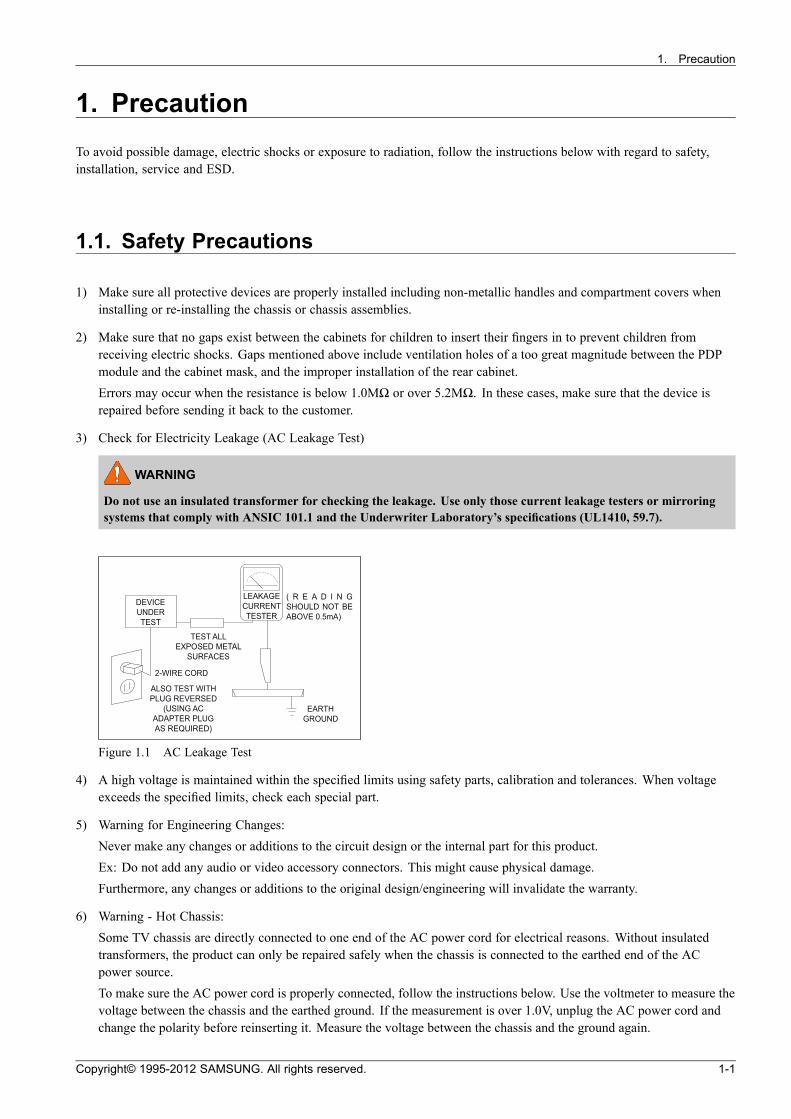
3) Check for Electricity Leakage (AC Leakage Test)
WARNING
Do not use an insulated transformer for checking the leakage. Use only those current leakage testers or mirroringsystems that comply with ANSIC 101.1 and the Underwriter Laboratory’s specifications (UL1410, 59.7).
DEVICEUNDER
TEST
LEAKAGECURREN T TESTER
TES T ALL EXPOSED ME TAL
SUR FACES
2-WIRE CORD
ALSO TES T WITH PLUG REVERSED
(USING AC ADAPTER PLUG AS REQU IRED)
EARTH GROUND
( R E A D I N G SHOULD NOT BE ABOVE 0.5mA)
Figure 1.1 AC Leakage Test
4) A high voltage is maintained within the specified limits using safety parts, calibration and tolerances. When voltageexceeds the specified limits, check each special part.
5) Warning for Engineering Changes:Never make any changes or additions to the circuit design or the internal part for this product.Ex: Do not add any audio or video accessory connectors. This might cause physical damage.Furthermore, any changes or additions to the original design/engineering will invalidate the warranty.
6) Warning - Hot Chassis:Some TV chassis are directly connected to one end of the AC power cord for electrical reasons. Without insulatedtransformers, the product can only be repaired safely when the chassis is connected to the earthed end of the ACpower source.To make sure the AC power cord is properly connected, follow the instructions below. Use the voltmeter to measure thevoltage between the chassis and the earthed ground. If the measurement is over 1.0V, unplug the AC power cord andchange the polarity before reinserting it. Measure the voltage between the chassis and the ground again.
Copyright© 1995-2012 SAMSUNG. All rights reserved. 1-1
1. Precaution
7) Some TV chassis are shipped with an additional secondary grounding system. The secondary system is adjacent tothe AC power line. These two grounding systems are separated in the circuit using an unbreakable/unchangeableinsulation material.
8) When any parts, material or wiring appear overheated or damaged, replace them with new regular ones immediately.When any damage or overheating is detected, correct this immediately and make a regular check of possible errors.
9) Check for the original shape of the lead, especially that of the antenna wiring, any sharp edges, the AC power and thehigh voltage power. Carefully check if the wiring is too tight, incorrectly placed or loose. Never change the spacebetween the part and the printed circuit board. Check the AC power cord for possible damages. Keep the part or thelead away from any heat-emitting materials.
10) Safety Indication:Some electrical circuits or device related materials require special attention to their safety features, which cannot beviewed by the naked eye. If an original part is replaced with another irregular one, the safety or protective features willbe lost even if the new one has a higher voltage or more watts.Critical safety parts should be bracketed with ( , ). Use only regular parts for replacements (in particular, flameresistance and dielectric strength specifications). Irregular parts or materials may cause electric shock or fire.
1-2 Copyright© 1995-2012 SAMSUNG. All rights reserved.
1. Precaution
1.2. Servicing Precautions
WARNING
1) First carefully read the “Safety Instruction” in this service manual.When there is a conflict between the service and the safety instructions, follow the safety instruction at all times.
2) Any electrolytic capacitor with the wrong polarity will explode.
1) The service instructions are printed on the cabinet, and should be followed by any service personnel.
2) Make sure to unplug the AC power cord from the power source before starting any repairs.a) Remove or re-install parts or assemblies.b) Disconnect the electric plug or connector, if any.c) Connect the test part in parallel with the electrolytic capacitor.
3) Some parts are placed at a higher position than the printed board. Insulated tubes or tapes are used for this purpose.The internal wiring is clamped using buckles to avoid contact with heat emitting parts. These parts are installed backto their original position.
4) After the repair, make sure to check if the screws, parts or cables are properly installed. Make sure no damage is causedto the repaired part and its surroundings.
5) Check for insulation between the blade of the AC plug and that of any conductive materials (i.e. the metal panel,input terminal, earphone jack, etc).
6) Insulation Check Process:Unplug the power cord from the AC source and turn the switch on. Connect the insulating resistance meter (500V) tothe AC plug blade. The insulating resistance between the blade of the AC plug and that of the conductive materialshould be more than 1MΩ.
7) Any B+ interlock should not be damaged.If the metal heat sink is not properly installed, no connection to the AC power should be made.
8) Make sure the grounding lead of the tester is connected to the chassis ground before connecting to the positive lead.The ground lead of the tester should be removed last.
9) Beware of risks of any current leakage coming into contact with the high-capacity capacitor.
10) The sharp edges of the metal material may cause physical damage, so protect yourself by wearing gloves during therepair.
11) Due to the nature of plasma display panels, partial after-images may appear if a still picture is displayed on the screenfor a long period of time.This is caused by brightness deterioration due to the storage effect of the panel, and to prevent this from happening, werecommend that the brightness and contrast are reduced. (e.g.) Contrast: 25, Brightness: 50
Copyright© 1995-2012 SAMSUNG. All rights reserved. 1-3
1. Precaution
1.3. Static Electricity Precautions
1) Some semi-conductive (“solid state”) devices are vulnerable to static electricity. These devices are known as ESD.ESD includes the integrated circuit and the field effect transistor. To avoid any materials damage from electrostaticshock, follow the instructions described below.
2) Remove any static electricity from your body by connecting the earth ground before handling any semi-conductive partsor assemblies. Alternatively, wear a dischargeable wrist-belt.(Make sure to remove any static electricity before connecting the power source - this is a safety instruction foravoiding electric shock)
3) Remove the ESD assembly and place it on a conductive surface such as aluminum foil to prevent accumulating staticelectricity.
4) Do not use any Freon-based chemicals. Such chemicals will generate static electricity that causes damage to the ESD.
5) Use only grounded-tip irons for soldering purposes.
6) Use only anti-static solder removal devices.Most solder removal devices do not support an anti-static feature. A solder removal device without an anti-static featurecan store enough static electricity to cause damage to the ESD.
7) Do not remove the ESD from the protective box until the replacement is ready. Most ESD replacements are covered withlead, which will cause a short to the entire unit due to the conductive foam, aluminum foil or other conductive materials.
8) Remove the protective material from the ESD replacement lead immediately after connecting it to the chassis orcircuit assembly.
9) Take extreme caution in handling any uncovered ESD replacements. Actions such as brushing clothes or lifting your legfrom the carpet floor can generate enough static electricity to damage the ESD.
CAUTION
These servicing instructions are for use by qualified service personnel only.
To reduce the risk of electric shock do not perform any servicing other than that contained in the operating instructionsunless you are qualified to do so.
1-4 Copyright© 1995-2012 SAMSUNG. All rights reserved.
1. Precaution
1.4. Installation Precautions
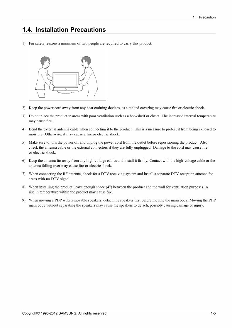
1) For safety reasons a minimum of two people are required to carry this product.
2) Keep the power cord away from any heat emitting devices, as a melted covering may cause fire or electric shock.
3) Do not place the product in areas with poor ventilation such as a bookshelf or closet. The increased internal temperaturemay cause fire.
4) Bend the external antenna cable when connecting it to the product. This is a measure to protect it from being exposed tomoisture. Otherwise, it may cause a fire or electric shock.
5) Make sure to turn the power off and unplug the power cord from the outlet before repositioning the product. Alsocheck the antenna cable or the external connectors if they are fully unplugged. Damage to the cord may cause fireor electric shock.
6) Keep the antenna far away from any high-voltage cables and install it firmly. Contact with the high-voltage cable or theantenna falling over may cause fire or electric shock.
7) When connecting the RF antenna, check for a DTV receiving system and install a separate DTV reception antenna forareas with no DTV signal.
8) When installing the product, leave enough space (4”) between the product and the wall for ventilation purposes. Arise in temperature within the product may cause fire.
9) When moving a PDP with removable speakers, detach the speakers first before moving the main body. Moving the PDPmain body without separating the speakers may cause the speakers to detach, possibly causing damage or injury.
Copyright© 1995-2012 SAMSUNG. All rights reserved. 1-5
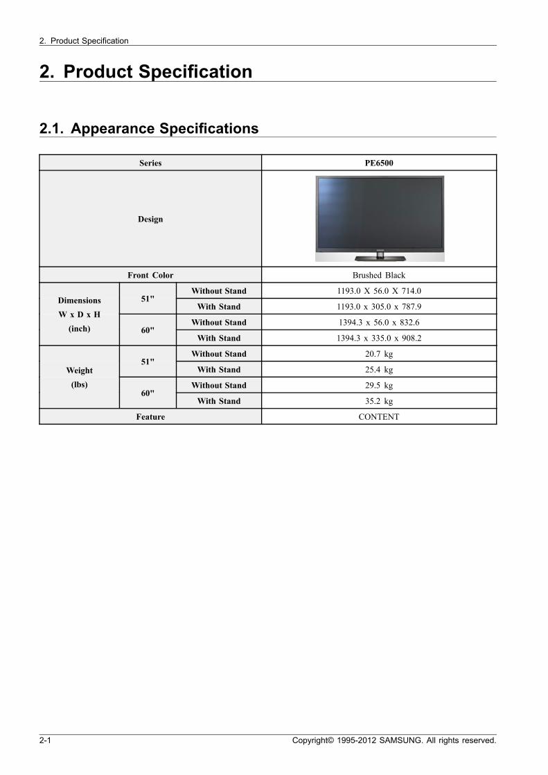
2. Product Specification
2. Product Specification
2.1. Appearance Specifications
Series PE6500
Design
Front Color Brushed Black
Without Stand 1193.0 X 56.0 X 714.051"
With Stand 1193.0 x 305.0 x 787.9
Without Stand 1394.3 x 56.0 x 832.6
Dimensions
W x D x H
(inch) 60"With Stand 1394.3 x 335.0 x 908.2
Without Stand 20.7 kg51"
With Stand 25.4 kg
Without Stand 29.5 kg
Weight
(lbs)60"
With Stand 35.2 kg
Feature CONTENT
2-1 Copyright© 1995-2012 SAMSUNG. All rights reserved.
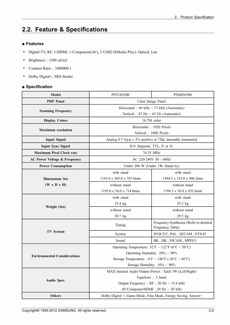
2. Product Specification
2.2. Feature & Specifications
Features
• Digital-TV, RF, 3-HDMI, 1-Component(AV), 2-USB2.0(Media Play), Optical, Lan
• Brightness : 1500 cd/m2
• Contrast Ratio : 1000000:1
• Dolby Digital+, SRS theater
Specification
Model PN51E6500 PN60E6500
PDP Panel Clear Image Panel
Scanning FrequencyHorizontal : 60 kHz ~ 73 kHz (Automatic)
Vertical : 47 Hz ~ 63 Hz (Automatic)
Display Colors 16.7M color
Maximum resolutionHorizontal : 1920 Pixels
Vertical : 1080 Pixels
Input Signal Analog 0.7 Vp-p ± 5% positive at 75Ω, internally terminated
Input Sync Signal H/V Separate, TTL, P. or N.
Maximum Pixel Clock rate 74.25 MHz
AC Power Voltage & Frequency AC 220-240V 50 / 60Hz
Power Consumption Under 280 W (Under 1W, Stand by)
with stand
1193.0 x 305.0 x 787.9mm
with stand
1394.3 x 335.0 x 908.2mmDimensions Set
(W x D x H) without stand
1193.0 x 56.0 x 714.0mm
without stand
1394.3 x 56.0 x 832.6mm
with stand
25.4 kg
with stand
35.2 kgWeight (Set)
without stand
20.7 kg
without stand
29.5 kg
TuningFrequency Synthesize (Refer to detailedFrequency Table)
System DVB-T/C, PAL , SECAM , NT4.43TV System
Sound BK , DK , NICAM , MPEG1
Environmental Considerations
Operating Temperature: 32˚F ~ 122˚F (0˚C ~ 50˚C)
Operating Humidity: 20% ~ 90%
Storage Temperature: -4˚F ~ 140˚F (-20˚C ~ 60˚C)
Storage Humidity: 10% ~ 90%
Audio Spec.
MAX Internal Audio Output Power : Each 3W (Left/Right)
Equalizer : 5 band
Output Frequency : RF : 20 Hz ~ 15.4 kHz
AV/Componet/HDMI : 20 Hz ~ 20 kHz
Others Dolby Digital +, Game Mode, Film Mode, Energy Saving, Anynet+
Copyright© 1995-2012 SAMSUNG. All rights reserved. 2-2
2. Product Specification
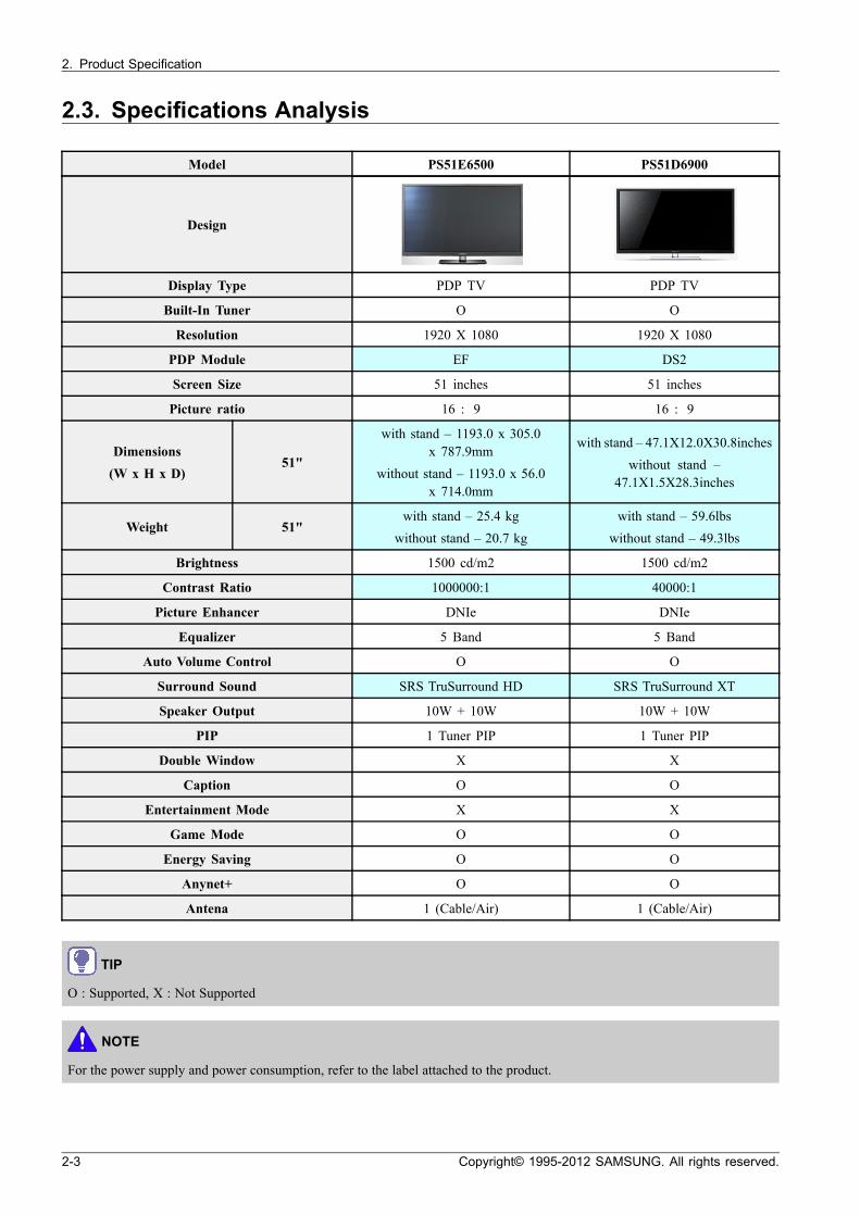
2.3. Specifications Analysis
Model PS51E6500 PS51D6900
Design
Display Type PDP TV PDP TV
Built-In Tuner O O
Resolution 1920 X 1080 1920 X 1080
PDP Module EF DS2
Screen Size 51 inches 51 inches
Picture ratio 16 : 9 16 : 9
Dimensions
(W x H x D)51"
with stand – 1193.0 x 305.0x 787.9mm
without stand – 1193.0 x 56.0x 714.0mm
with stand – 47.1X12.0X30.8inches
without stand –47.1X1.5X28.3inches
Weight 51"with stand – 25.4 kg
without stand – 20.7 kg
with stand – 59.6lbs
without stand – 49.3lbs
Brightness 1500 cd/m2 1500 cd/m2
Contrast Ratio 1000000:1 40000:1
Picture Enhancer DNIe DNIe
Equalizer 5 Band 5 Band
Auto Volume Control O O
Surround Sound SRS TruSurround HD SRS TruSurround XT
Speaker Output 10W + 10W 10W + 10W
PIP 1 Tuner PIP 1 Tuner PIP
Double Window X X
Caption O O
Entertainment Mode X X
Game Mode O O
Energy Saving O O
Anynet+ O O
Antena 1 (Cable/Air) 1 (Cable/Air)
TIP
O : Supported, X : Not Supported
NOTE
For the power supply and power consumption, refer to the label attached to the product.
2-3 Copyright© 1995-2012 SAMSUNG. All rights reserved.
2. Product Specification
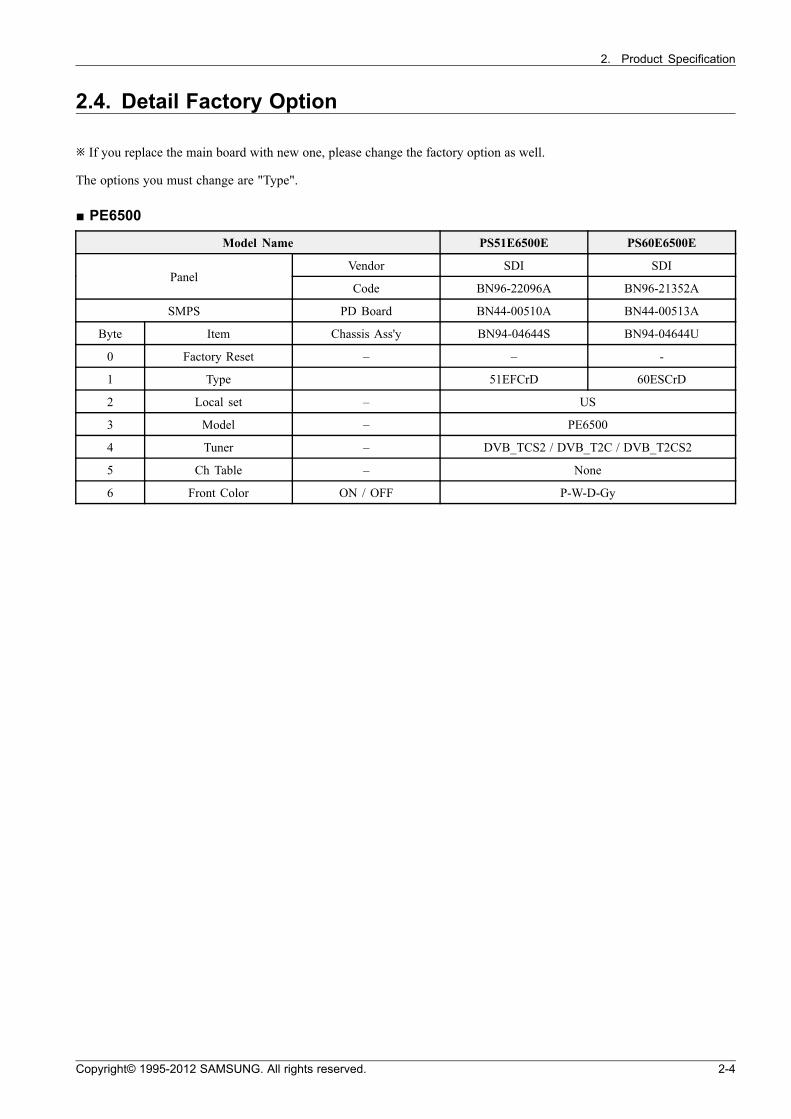
2.4. Detail Factory Option
※ If you replace the main board with new one, please change the factory option as well.
The options you must change are "Type".
PE6500
Model Name PS51E6500E PS60E6500E
Vendor SDI SDIPanel
Code BN96-22096A BN96-21352A
SMPS PD Board BN44-00510A BN44-00513A
Byte Item Chassis Ass'y BN94-04644S BN94-04644U
0 Factory Reset – – -
1 Type 51EFCrD 60ESCrD
2 Local set – US
3 Model – PE6500
4 Tuner – DVB_TCS2 / DVB_T2C / DVB_T2CS2
5 Ch Table – None
6 Front Color ON / OFF P-W-D-Gy
Copyright© 1995-2012 SAMSUNG. All rights reserved. 2-4
2. Product Specification
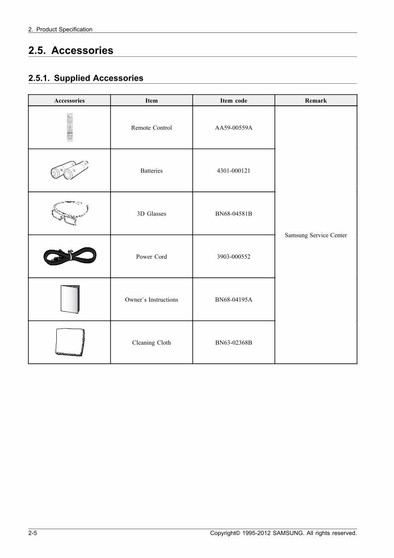
2.5. Accessories
2.5.1. Supplied Accessories
Accessories Item Item code Remark
SOURCE
MUTE
MENU SEARCH
INFOTOOLS
RETURN
Family S tory MTS
SUPPORT P.SIZE CC
EXIT
PR E-CH
CHLIST
M
B C D
l l ll
Remote Control AA59-00559A
Batteries 4301-000121
3D Glasses BN68-04581B
Power Cord 3903-000552
Owner`s Instructions BN68-04195A
Cleaning Cloth BN63-02368B
Samsung Service Center
2-5 Copyright© 1995-2012 SAMSUNG. All rights reserved.
2. Product Specification
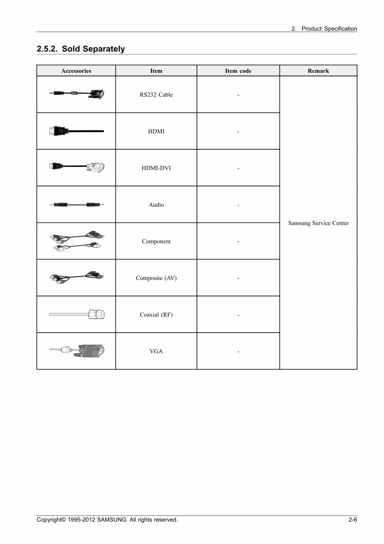
2.5.2. Sold Separately
Accessories Item Item code Remark
RS232 Cable -
HDMI -
HDMI-DVI -
Audio -
Component -
Composite (AV) -
Coaxial (RF) -
VGA -
Samsung Service Center
Copyright© 1995-2012 SAMSUNG. All rights reserved. 2-6
3. Disassembly and Reassembly
3. Disassembly and Reassembly
This section of the service manual describes the disassembly and reassembly procedures for the PDP TV.
WARNING
This PDP TV contains electrostatically sensitive devices. Use caution when handling these components.
3.1. Overall Disassembly and Reassembly
CAUTION
• Disconnect the PDP TV from the power source before disassembly.
• Follow these directions carefully; never use metal instruments to pry apart the cabinet.
• If there is no additional comment, it is same for all inches.
Description Description Photo Screw
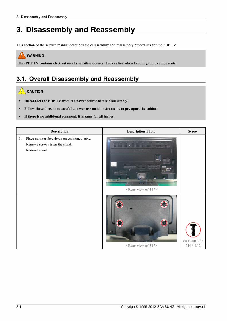
1. Place monitor face down on cushioned table.
Remove screws from the stand.
Remove stand.
<Rear view of 51">
<Rear view of 51">6003–001782M4 * L12
3-1 Copyright© 1995-2012 SAMSUNG. All rights reserved.
3. Disassembly and Reassembly
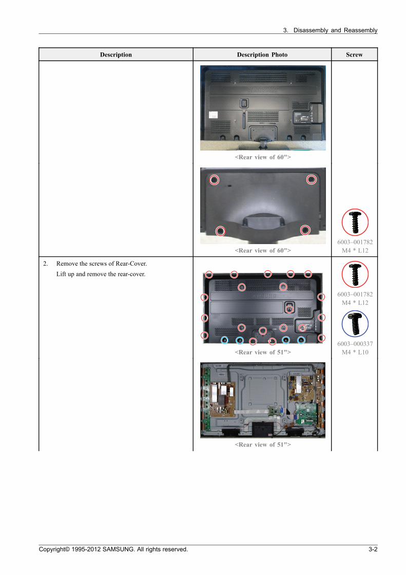
Description Description Photo Screw
<Rear view of 60">
<Rear view of 60">6003–001782M4 * L12
2. Remove the screws of Rear-Cover.
Lift up and remove the rear-cover.
<Rear view of 51">
6003–001782M4 * L12
6003–000337M4 * L10
<Rear view of 51">
Copyright© 1995-2012 SAMSUNG. All rights reserved. 3-2
3. Disassembly and Reassembly
Description Description Photo Screw
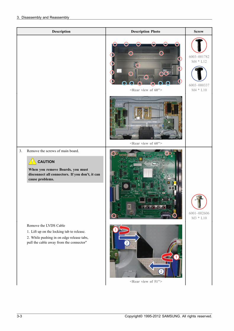
<Rear view of 60">
6003–001782M4 * L12
6003–000337M4 * L10
<Rear view of 60">
3. Remove the screws of main board.
CAUTION
When you remove Boards, you mustdisconnect all connectors. If you don't, it cancause problems.
6001–002606M3 * L10
Remove the LVDS Cable
1. Lift up on the locking tab to release.
2. While pushing in on edge release tabs,pull the cable away from the connector" 2
2
1
1
<Rear view of 51">
3-3 Copyright© 1995-2012 SAMSUNG. All rights reserved.
3. Disassembly and Reassembly
Description Description Photo Screw
1
2
<Rear view of 60">
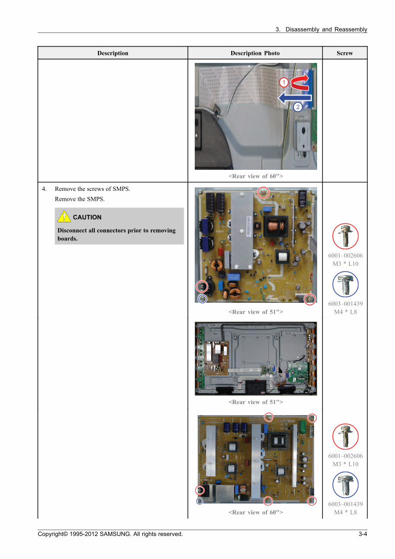
4. Remove the screws of SMPS.
Remove the SMPS.
CAUTION
Disconnect all connectors prior to removingboards.
<Rear view of 51">
6001–002606M3 * L10
6003–001439M4 * L8
<Rear view of 51">
<Rear view of 60">
6001–002606M3 * L10
6003–001439M4 * L8
Copyright© 1995-2012 SAMSUNG. All rights reserved. 3-4
3. Disassembly and Reassembly
Description Description Photo Screw
<Rear view of 60">
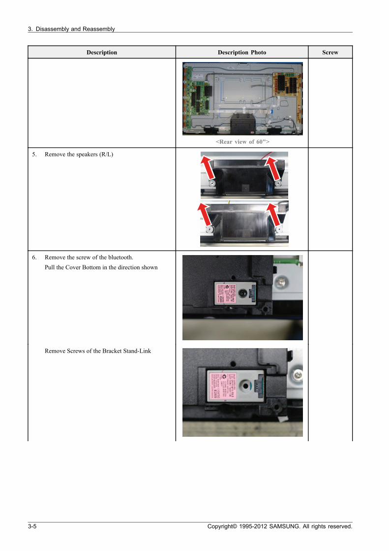
5. Remove the speakers (R/L)
6. Remove the screw of the bluetooth.
Pull the Cover Bottom in the direction shown
Remove Screws of the Bracket Stand-Link
3-5 Copyright© 1995-2012 SAMSUNG. All rights reserved.
3. Disassembly and Reassembly
Description Description Photo Screw
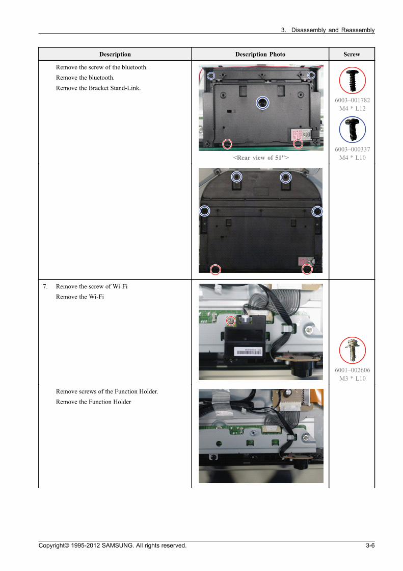
Remove the screw of the bluetooth.
Remove the bluetooth.
Remove the Bracket Stand-Link.
<Rear view of 51">
6003–001782M4 * L12
6003–000337M4 * L10
7. Remove the screw of Wi-Fi
Remove the Wi-Fi
6001–002606M3 * L10
Remove screws of the Function Holder.
Remove the Function Holder
Copyright© 1995-2012 SAMSUNG. All rights reserved. 3-6
3. Disassembly and Reassembly
Description Description Photo Screw
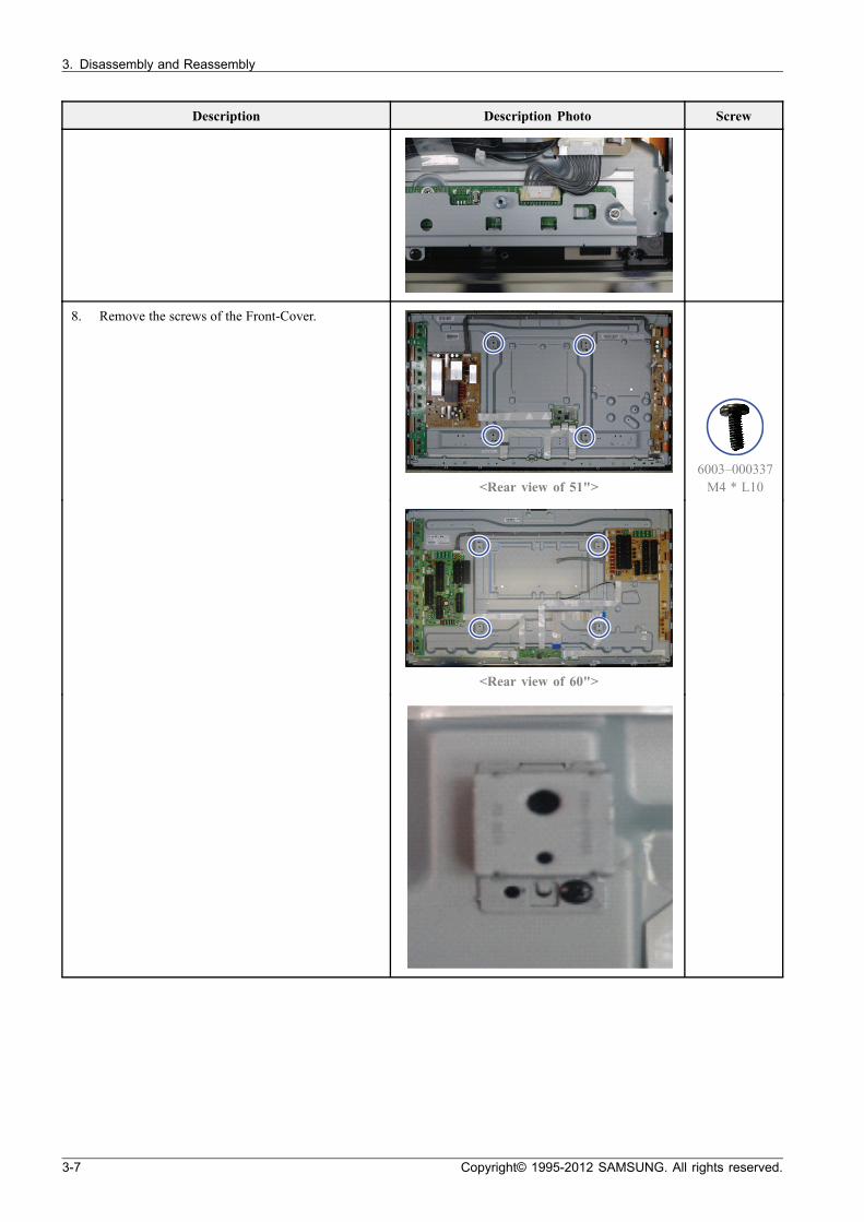
8. Remove the screws of the Front-Cover.
<Rear view of 51">6003–000337M4 * L10
<Rear view of 60">
3-7 Copyright© 1995-2012 SAMSUNG. All rights reserved.
3. Disassembly and Reassembly
Description Description Photo Screw
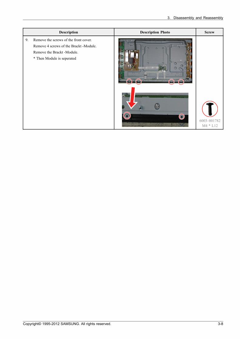
9. Remove the screws of the front cover.
Remove 4 screws of the Brackt -Module.
Remove the Brackt -Module.
* Then Module is seperated
6003–001782M4 * L12
Copyright© 1995-2012 SAMSUNG. All rights reserved. 3-8
4. Troubleshooting
4. Troubleshooting
4.1. Checkpoints by Error Mode
4.1.1. First Checklist for Troubleshooting
1) Check the various cable connections first.
• Check to see if there is a burnt or damaged cable.
• Check to see if there is a disconnected or loose cable connection.
• Check to see if the cables are connected according to the connection diagram.
2) Check the power input to the Main Board.
3) How to distinguish if the problem is caused by Main board or Logic Board.
• No Video : If the problem is No Video but Logic Board is on and Indication LED is blinking repeatedly andfaster than normal booting, replace the T-Con board.
• Distorted Picture : Check the inner patterns.
Inner pattern Picture Problem
OK NG Main board
NG NG Main or LVDS cable or Logic Board or Panel.
• How to check inner pattern?a. Entering Factory mode.b. Move to SVC menu.c. Move to Test Pattern.d. Check inner patterns.
4-1 Copyright© 1995-2012 SAMSUNG. All rights reserved.
4. Troubleshooting
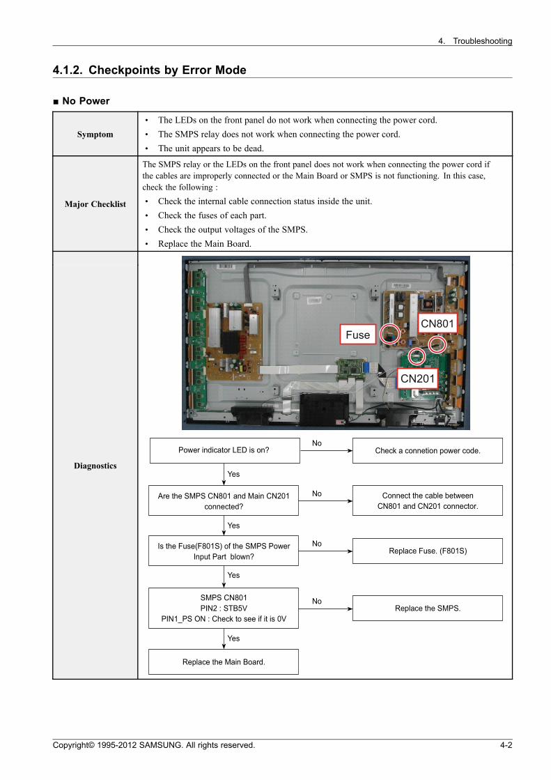
4.1.2. Checkpoints by Error Mode
No Power
Symptom
• The LEDs on the front panel do not work when connecting the power cord.• The SMPS relay does not work when connecting the power cord.• The unit appears to be dead.
Major Checklist
The SMPS relay or the LEDs on the front panel does not work when connecting the power cord ifthe cables are improperly connected or the Main Board or SMPS is not functioning. In this case,check the following :
• Check the internal cable connection status inside the unit.• Check the fuses of each part.• Check the output voltages of the SMPS.• Replace the Main Board.
DiagnosticsYes
Yes
Yes
Yes
Power indica tor LED is on? Check a conne tion power code .
Replace the Main Board.
Connect the cable be tweenCN801 and CN201 connector.
Are the SMPS CN801 and Main CN201connected?
Replace Fuse . (F801S)Is th e Fuse(F801S) of the SMPS Power
Input Part blown?
Replace the SMPS.SMPS CN801PIN2 : STB5V
PIN1_PS ON : Check to see if it is 0V
No
No
No
No
Copyright© 1995-2012 SAMSUNG. All rights reserved. 4-2
4. Troubleshooting
CAUTION
Make sure to disconnect the power before working on the SMPS board.
4-3 Copyright© 1995-2012 SAMSUNG. All rights reserved.
4. Troubleshooting
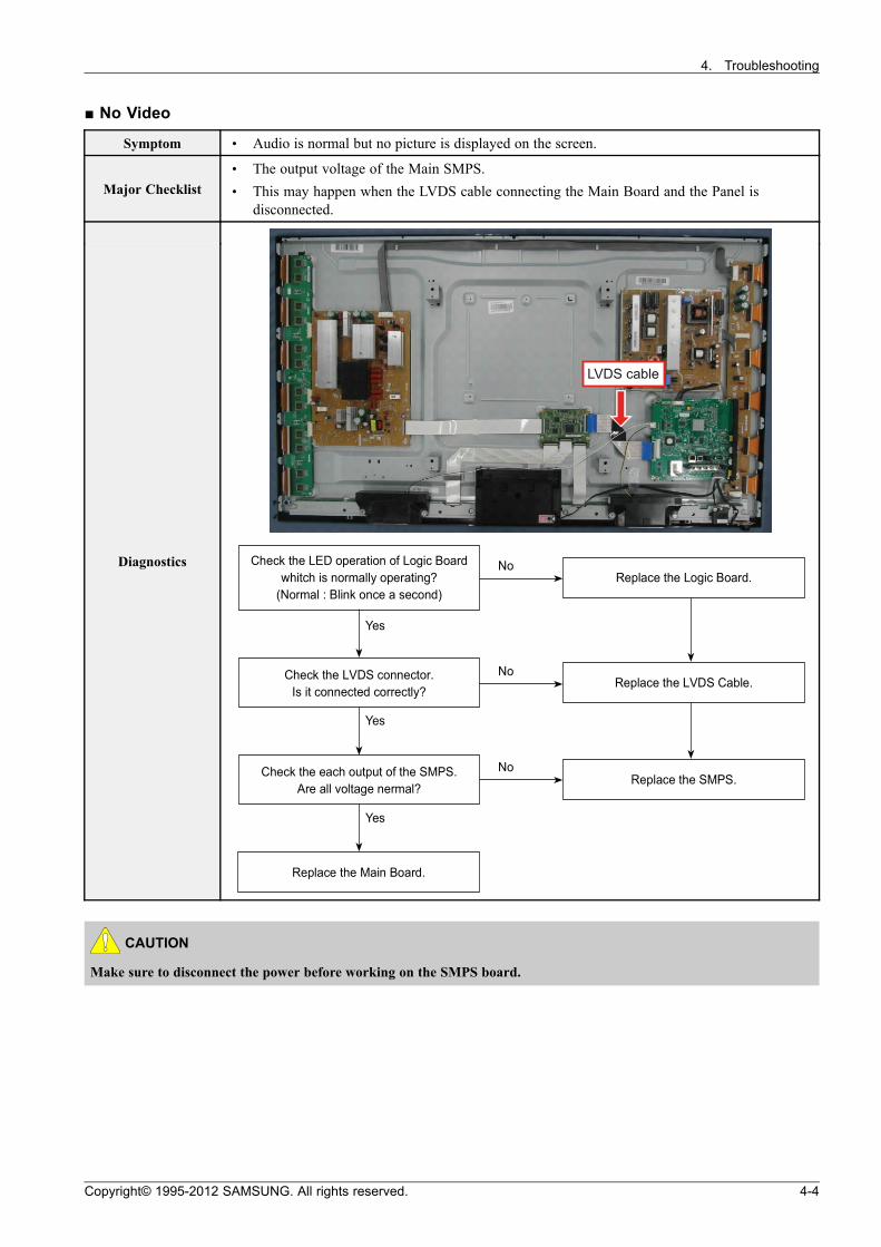
No Video
Symptom • Audio is normal but no picture is displayed on the screen.
Major Checklist• The output voltage of the Main SMPS.• This may happen when the LVDS cable connecting the Main Board and the Panel is
disconnected.
Diagnostics
Yes
Yes
Yes
Replace the Main Board.
Replace the LVDS Cable .Check the LVDS connector.
Is it connected correctly?
Replace the SMPS.Check the each output of the SMPS.
Are a ll voltage nerma l?
Replace the Logic Board.Check the LED opera tion of Logic Board
whitch is normally opera ting?(Normal : Blink once a second)
No
No
No
CAUTION
Make sure to disconnect the power before working on the SMPS board.
Copyright© 1995-2012 SAMSUNG. All rights reserved. 4-4
4. Troubleshooting
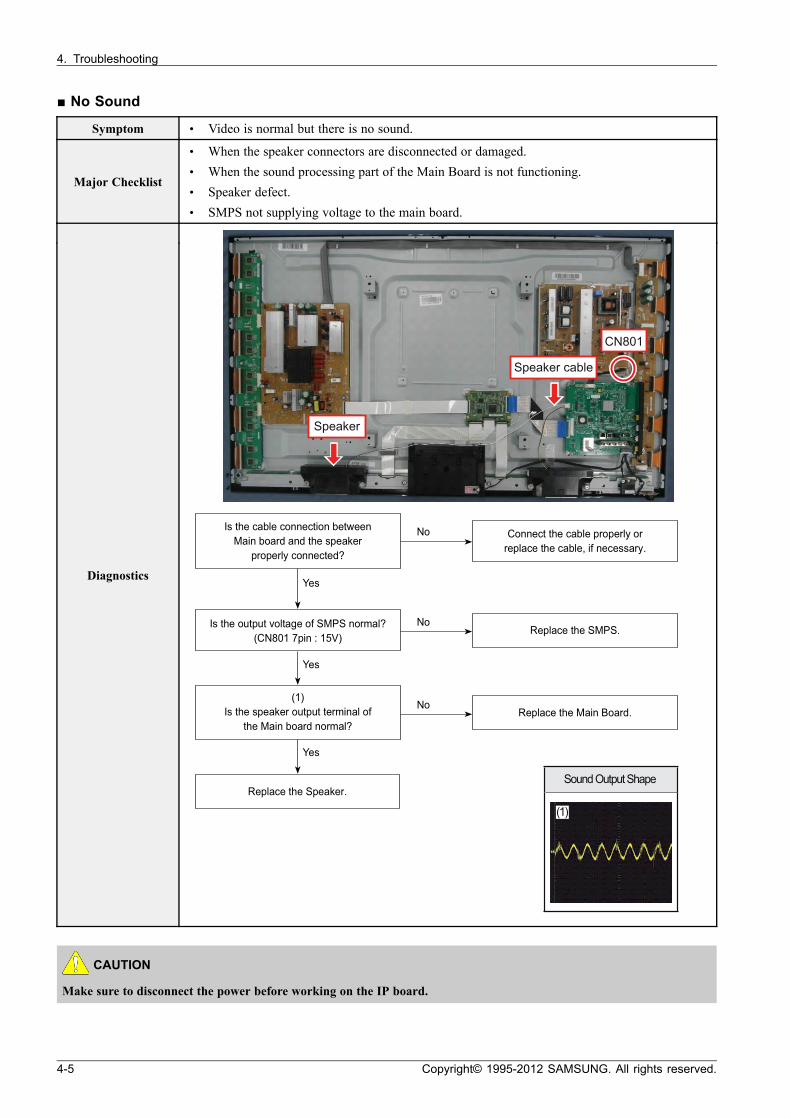
No Sound
Symptom • Video is normal but there is no sound.
Major Checklist
• When the speaker connectors are disconnected or damaged.• When the sound processing part of the Main Board is not functioning.• Speaker defect.• SMPS not supplying voltage to the main board.
DiagnosticsYes
Yes
Yes
Replace the Speaker.
Replace the SMPS.Is th e output voltage of SMPS normal?
(CN801 7pin : 15V)
Replace the Main Board.
(1)Is the speaker output te rmina l of
the Main board normal?
Connect the cable properly orreplace the cable, if necessary.
Is the cable connection be tweenMain board and the speaker
properly connected?
No
No
No
Sound Output Shape
(1)
CAUTION
Make sure to disconnect the power before working on the IP board.
4-5 Copyright© 1995-2012 SAMSUNG. All rights reserved.
4. Troubleshooting
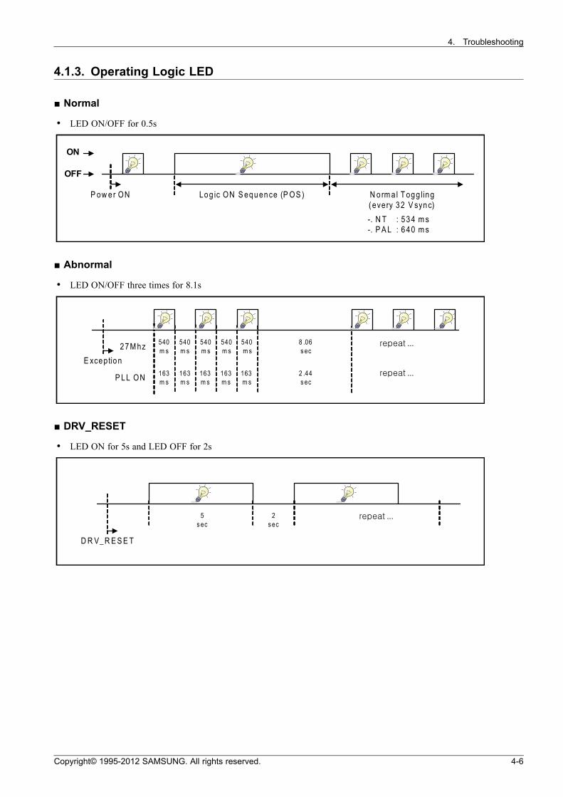
4.1.3. Operating Logic LED
Normal
• LED ON/OFF for 0.5s
OFF
ON
P ower ON Logic ON S equence (P OS ) Normal Toggling (eve ry 32 Vsync)
-. NT : 534 ms-. P AL : 640 ms
Abnormal
• LED ON/OFF three times for 8.1s
540ms
8 .06 s ec
Exception
540ms
540ms
540ms
540ms27Mhz
2.44s ec
163msP LL ON
163ms
163ms
163ms
163ms
·· ªª µµ ªª ¦¦ ¹¹ee ...
·· ªª µµ ªª ¦¦ ¹¹ee ...
DRV_RESET
• LED ON for 5s and LED OFF for 2s
5 s ec
·· ªª µµ ªª ¦¦ ¹¹ee ...
DRV_RES ET
2 s ec
Copyright© 1995-2012 SAMSUNG. All rights reserved. 4-6
4. Troubleshooting
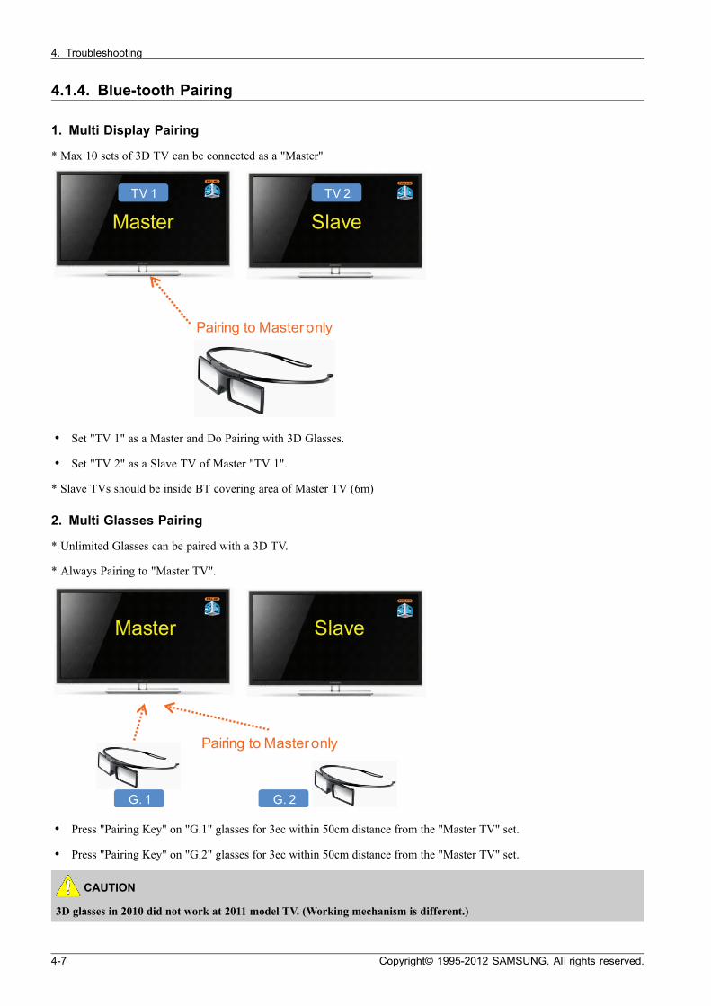
4.1.4. Blue-tooth Pairing
1. Multi Display Pairing
* Max 10 sets of 3D TV can be connected as a "Master"
Master
TV 1
S lave
TV 2
Pa iring to Mas te r only
• Set "TV 1" as a Master and Do Pairing with 3D Glasses.
• Set "TV 2" as a Slave TV of Master "TV 1".
* Slave TVs should be inside BT covering area of Master TV (6m)
2. Multi Glasses Pairing
* Unlimited Glasses can be paired with a 3D TV.
* Always Pairing to "Master TV".
Master S lave
G. 1 G. 2
Pa iring to Mas te r only
• Press "Pairing Key" on "G.1" glasses for 3ec within 50cm distance from the "Master TV" set.
• Press "Pairing Key" on "G.2" glasses for 3ec within 50cm distance from the "Master TV" set.
CAUTION
3D glasses in 2010 did not work at 2011 model TV. (Working mechanism is different.)
4-7 Copyright© 1995-2012 SAMSUNG. All rights reserved.

4. Troubleshooting
4.2. Factory Mode Adjustments
4.2.1. Entering Factory Mode
To enter ‘Service Mode’ Press the remote-control keys in this sequence.
• If you do not have Factory remote-control.
¾¾ ÆÆ ´ ÁÁoo oo ¾¾ ÆÆ ´ ÁÁoo ¤¤ oo ¤¤ ££ oo
• If you have Factory remote-control.
INFO Factory
Copyright© 1995-2012 SAMSUNG. All rights reserved. 4-8

4. Troubleshooting
• If you don’t have Factory remote control, can’t control some menu.
Option
Control
SVC
Expert
ADC/WB
Advanced
T-MST10PDEUC-xxxx
T-MST10PDEUCS-xxxx
E-Manual:XTDVBEUE-xxxx
EDID : SUCCESS
HDCP : SUCCESS
CALIB : AV/COMP/PC/HDMI
Option : xxxxxxxx,xxxx,xxxx,xxxx
FactoryCS : 0xxxxxxxxx
T-MSXDEUCIP-xxxx
Onboot : xxxx
SDAL-xxxx.xxxx
RFS:"X10P xxxx
2012-xx-xx
Echo-Fs : 0xxxxx
Bluetooth:xxxx
Type : xxxxxxxx
Model : PSxxE6500
Logic S/W : xx-xx-xx
Wired MAC SUCCESS
Wireless MAC SUCCESS
CIP SUCCESS
DRM :Cert O, Nf O, Wv O, Hc X, Dc X, Mx O, MI X
Factory Data Ver : xxx
DTP-AP-COMP-xxx
DTP-BP-HAL-xxxx
DTP-BP-xxxx
POP-FLA-xx-xxxx
Date of purchase : mm/dd/yyyy
4-9 Copyright© 1995-2012 SAMSUNG. All rights reserved.
4. Troubleshooting
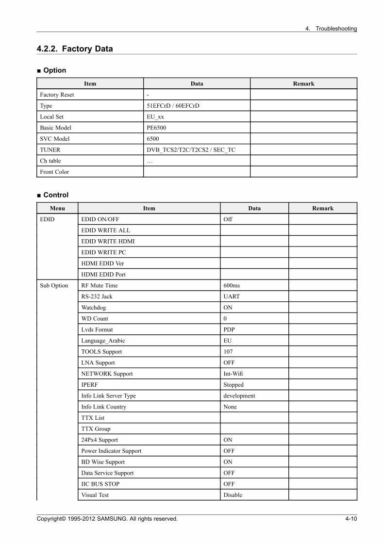
4.2.2. Factory Data
Option
Item Data Remark
Factory Reset -
Type 51EFCrD / 60EFCrD
Local Set EU_xx
Basic Model PE6500
SVC Model 6500
TUNER DVB_TCS2/T2C/T2CS2 / SEC_TC
Ch table …
Front Color
Control
Menu Item Data Remark
EDID EDID ON/OFF Off
EDID WRITE ALL
EDID WRITE HDMI
EDID WRITE PC
HDMI EDID Ver
HDMI EDID Port
Sub Option RF Mute Time 600ms
RS-232 Jack UART
Watchdog ON
WD Count 0
Lvds Format PDP
Language_Arabic EU
TOOLS Support 107
LNA Support OFF
NETWORK Support Int-Wifi
IPERF Stopped
Info Link Server Type development
Info Link Country None
TTX List
TTX Group
24Px4 Support ON
Power Indicator Support OFF
BD Wise Support ON
Data Service Support OFF
IIC BUS STOP OFF
Visual Test Disable
Copyright© 1995-2012 SAMSUNG. All rights reserved. 4-10
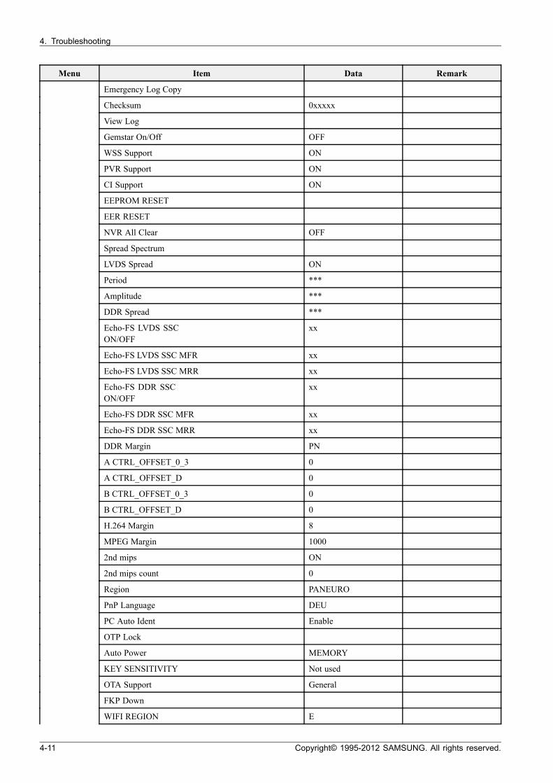
4. Troubleshooting
Menu Item Data Remark
Emergency Log Copy
Checksum 0xxxxx
View Log
Gemstar On/Off OFF
WSS Support ON
PVR Support ON
CI Support ON
EEPROM RESET
EER RESET
NVR All Clear OFF
Spread Spectrum
LVDS Spread ON
Period ***
Amplitude ***
DDR Spread ***
Echo-FS LVDS SSCON/OFF
xx
Echo-FS LVDS SSC MFR xx
Echo-FS LVDS SSC MRR xx
Echo-FS DDR SSCON/OFF
xx
Echo-FS DDR SSC MFR xx
Echo-FS DDR SSC MRR xx
DDR Margin PN
A CTRL_OFFSET_0_3 0
A CTRL_OFFSET_D 0
B CTRL_OFFSET_0_3 0
B CTRL_OFFSET_D 0
H.264 Margin 8
MPEG Margin 1000
2nd mips ON
2nd mips count 0
Region PANEURO
PnP Language DEU
PC Auto Ident Enable
OTP Lock
Auto Power MEMORY
KEY SENSITIVITY Not used
OTA Support General
FKP Down
WIFI REGION E
4-11 Copyright© 1995-2012 SAMSUNG. All rights reserved.
4. Troubleshooting
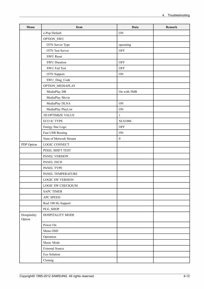
Menu Item Data Remark
e-Pop Default ON
OPTION_SWU
OTN Server Type operating
OTN Test Server OFF
SWU Reset
SWU Duration OFF
SWU Fail Test OFF
OTN Support ON
SWU_Diag_Code
OPTION_MEDIAPLAY
MediaPlay DB On with 5MB
MediaPlay Movie
MediaPlay DLNA ON
MediaPlay PlayList ON
3D OPTIMIZE VALUE 1
ECO IC TYPE NLS1006
Energy Star Logo OFF
Fast USB Booting ON
Num of Metwork Stream 0
PDP Option LOGIC CONNECT
PIXEL SHIFT TEST
PANEL VERSION
PANEL INCH
PANEL TYPE
PANEL TEMPERATURE
LOGIC SW VERSION
LOGIC SW CHECKSUM
SAPC TIMER
APC SPEED
Real 100 Hz Support
PLG_SHOP
HotspitalityOption
HOSPITALITY MODE
Power On
Menu OSD
Operation
Music Mode
External Source
Eco Solution
Cloning
Copyright© 1995-2012 SAMSUNG. All rights reserved. 4-12
4. Troubleshooting
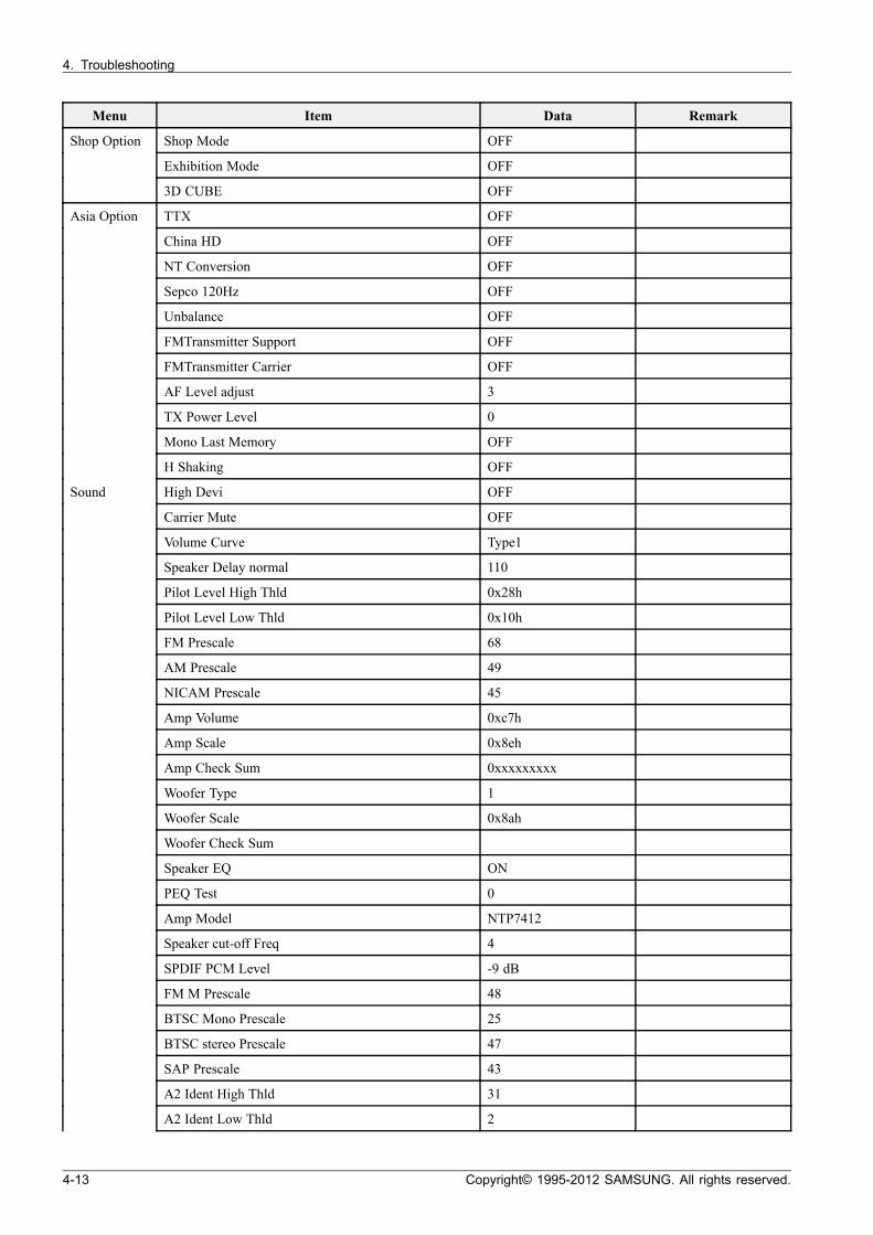
Menu Item Data Remark
Shop Mode OFF
Exhibition Mode OFF
Shop Option
3D CUBE OFF
Asia Option TTX OFF
China HD OFF
NT Conversion OFF
Sepco 120Hz OFF
Unbalance OFF
FMTransmitter Support OFF
FMTransmitter Carrier OFF
AF Level adjust 3
TX Power Level 0
Mono Last Memory OFF
H Shaking OFF
Sound High Devi OFF
Carrier Mute OFF
Volume Curve Type1
Speaker Delay normal 110
Pilot Level High Thld 0x28h
Pilot Level Low Thld 0x10h
FM Prescale 68
AM Prescale 49
NICAM Prescale 45
Amp Volume 0xc7h
Amp Scale 0x8eh
Amp Check Sum 0xxxxxxxxx
Woofer Type 1
Woofer Scale 0x8ah
Woofer Check Sum
Speaker EQ ON
PEQ Test 0
Amp Model NTP7412
Speaker cut-off Freq 4
SPDIF PCM Level -9 dB
FM M Prescale 48
BTSC Mono Prescale 25
BTSC stereo Prescale 47
SAP Prescale 43
A2 Ident High Thld 31
A2 Ident Low Thld 2
4-13 Copyright© 1995-2012 SAMSUNG. All rights reserved.
4. Troubleshooting
Menu Item Data Remark
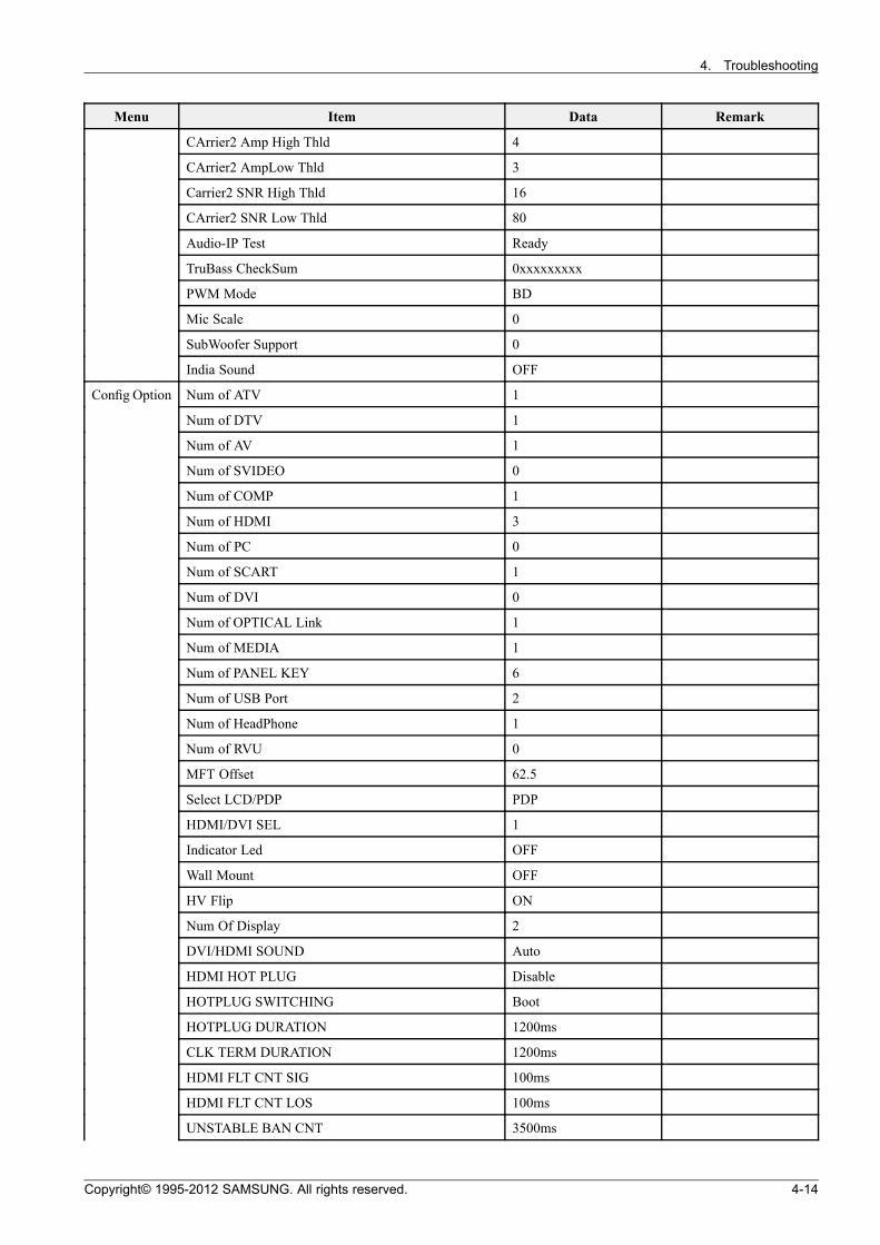
CArrier2 Amp High Thld 4
CArrier2 AmpLow Thld 3
Carrier2 SNR High Thld 16
CArrier2 SNR Low Thld 80
Audio-IP Test Ready
TruBass CheckSum 0xxxxxxxxx
PWM Mode BD
Mic Scale 0
SubWoofer Support 0
India Sound OFF
Config Option Num of ATV 1
Num of DTV 1
Num of AV 1
Num of SVIDEO 0
Num of COMP 1
Num of HDMI 3
Num of PC 0
Num of SCART 1
Num of DVI 0
Num of OPTICAL Link 1
Num of MEDIA 1
Num of PANEL KEY 6
Num of USB Port 2
Num of HeadPhone 1
Num of RVU 0
MFT Offset 62.5
Select LCD/PDP PDP
HDMI/DVI SEL 1
Indicator Led OFF
Wall Mount OFF
HV Flip ON
Num Of Display 2
DVI/HDMI SOUND Auto
HDMI HOT PLUG Disable
HOTPLUG SWITCHING Boot
HOTPLUG DURATION 1200ms
CLK TERM DURATION 1200ms
HDMI FLT CNT SIG 100ms
HDMI FLT CNT LOS 100ms
UNSTABLE BAN CNT 3500ms
Copyright© 1995-2012 SAMSUNG. All rights reserved. 4-14
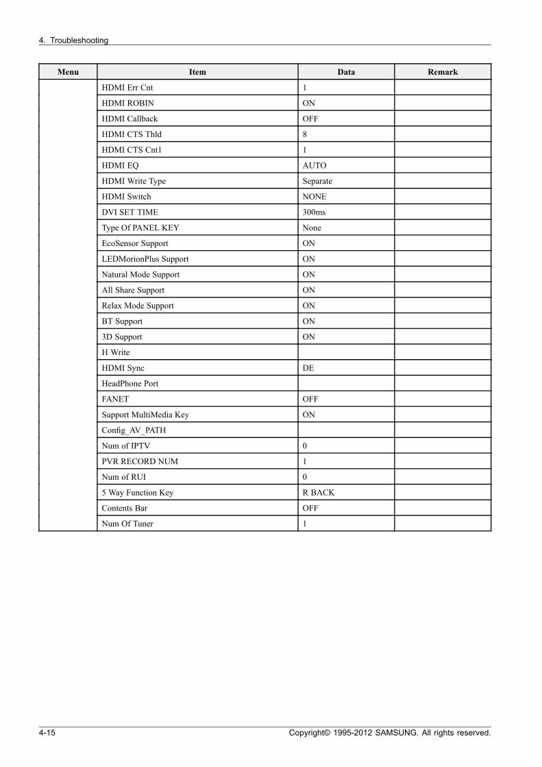
4. Troubleshooting
Menu Item Data Remark
HDMI Err Cnt 1
HDMI ROBIN ON
HDMI Callback OFF
HDMI CTS Thld 8
HDMI CTS Cnt1 1
HDMI EQ AUTO
HDMI Write Type Separate
HDMI Switch NONE
DVI SET TIME 300ms
Type Of PANEL KEY None
EcoSensor Support ON
LEDMorionPlus Support ON
Natural Mode Support ON
All Share Support ON
Relax Mode Support ON
BT Support ON
3D Support ON
H Write
HDMI Sync DE
HeadPhone Port
FANET OFF
Support MultiMedia Key ON
Config_AV_PATH
Num of IPTV 0
PVR RECORD NUM 1
Num of RUI 0
5 Way Function Key R BACK
Contents Bar OFF
Num Of Tuner 1
4-15 Copyright© 1995-2012 SAMSUNG. All rights reserved.
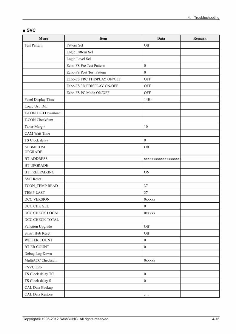
4. Troubleshooting
SVC
Menu Item Data Remark
Pattern Sel Off
Logic Pattern Sel
Test Pattern
Logic Level Sel
Echo-FS Pre Test Pattern 0
Echo-FS Post Test Pattern 0
Echo-FS FRC FDISPLAY ON/OFF OFF
Echo-FS 3D FDISPLAY ON/OFF OFF
Echo-FS PC Mode ON/OFF OFF
Panel Display Time 14Hr
Logic Usb D/L
T-CON USB Download
T-CON CheckSum
Tuner Margin 10
CAM Wait Time
TS Clock delay 0
SUBMICOMUPGRADE
Off
BT ADDRESS xxxxxxxxxxxxxxxxxxxx
BT UPGRADE
BT FREEPAIRING ON
SVC Reset
TCON_TEMP READ 37
TEMP LAST 37
DCC VERSION 0xxxxx
DCC CHK SEL 0
DCC CHECK LOCAL 0xxxxx
DCC CHECK TOTAL
Function Upgrade Off
Smart Hub Reset Off
WIFI ER COUNT 0
BT ER COUNT 0
Debug Log Down
MultiACC Checksum 0xxxxx
CSVC Info
TS Clock delay TC 0
TS Clock delay S 0
CAL Data Backup
CAL Data Restore ….
Copyright© 1995-2012 SAMSUNG. All rights reserved. 4-16
4. Troubleshooting
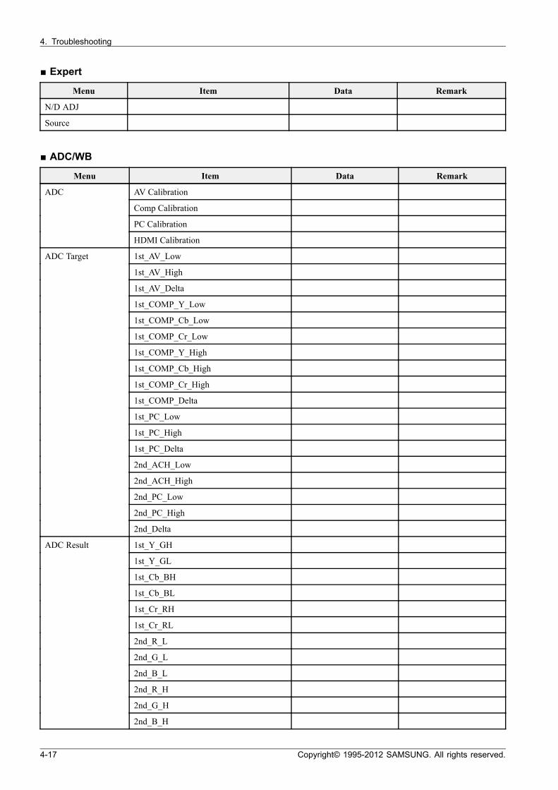
Expert
Menu Item Data Remark
N/D ADJ
Source
ADC/WB
Menu Item Data Remark
AV Calibration
Comp Calibration
PC Calibration
ADC
HDMI Calibration
1st_AV_Low
1st_AV_High
1st_AV_Delta
1st_COMP_Y_Low
1st_COMP_Cb_Low
1st_COMP_Cr_Low
1st_COMP_Y_High
1st_COMP_Cb_High
1st_COMP_Cr_High
1st_COMP_Delta
1st_PC_Low
1st_PC_High
1st_PC_Delta
2nd_ACH_Low
2nd_ACH_High
2nd_PC_Low
2nd_PC_High
ADC Target
2nd_Delta
1st_Y_GH
1st_Y_GL
1st_Cb_BH
1st_Cb_BL
1st_Cr_RH
1st_Cr_RL
2nd_R_L
2nd_G_L
2nd_B_L
2nd_R_H
2nd_G_H
ADC Result
2nd_B_H
4-17 Copyright© 1995-2012 SAMSUNG. All rights reserved.
4. Troubleshooting
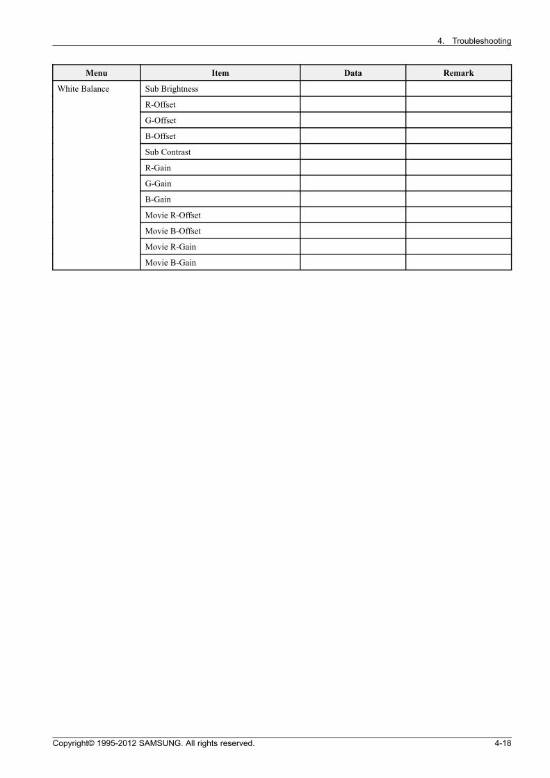
Menu Item Data Remark
Sub Brightness
R-Offset
G-Offset
B-Offset
Sub Contrast
R-Gain
G-Gain
B-Gain
Movie R-Offset
Movie B-Offset
Movie R-Gain
White Balance
Movie B-Gain
Copyright© 1995-2012 SAMSUNG. All rights reserved. 4-18
4. Troubleshooting
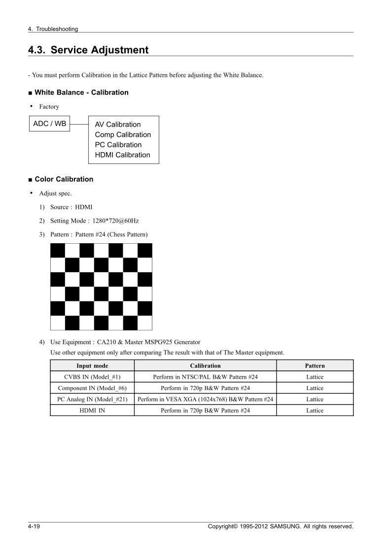
4.3. Service Adjustment
- You must perform Calibration in the Lattice Pattern before adjusting the White Balance.
White Balance - Calibration
• Factory
ADC / WB AV Calibration
Comp Calibration
PC Calibration
HDMI Calibration
Color Calibration
• Adjust spec.
1) Source : HDMI
2) Setting Mode : 1280*720@60Hz
3) Pattern : Pattern #24 (Chess Pattern)
4) Use Equipment : CA210 & Master MSPG925 GeneratorUse other equipment only after comparing The result with that of The Master equipment.
Input mode Calibration Pattern
CVBS IN (Model_#1) Perform in NTSC/PAL B&W Pattern #24 Lattice
Component IN (Model_#6) Perform in 720p B&W Pattern #24 Lattice
PC Analog IN (Model_#21) Perform in VESA XGA (1024x768) B&W Pattern #24 Lattice
HDMI IN Perform in 720p B&W Pattern #24 Lattice
4-19 Copyright© 1995-2012 SAMSUNG. All rights reserved.
4. Troubleshooting
• Method of Color Calibration (AV)
1) Apply the NTSC/PAL Lattice (N0. 3) pattern signal to the AV IN 1 port.
2) Press the Source key to switch to “AV1” mode.
3) Enter Service mode.
4) Select the “ADC” menu.
5) Select the “AV Calibration” menu.
6) In “AV Calibration Off” status, press the “ ” key to perform Calibration.
7) When Calibration is complete, it returns to the high-level menu.
8) You can see the change of the “AV Calibration” status from Failure to Success.
• Method of Color Calibration (Component)
1) Apply the 720p Lattice (N0. 6) pattern signal to the Component IN 1 port.
2) Press the Source key to switch to “Component1” mode.
3) Enter Service mode.
4) Select the “ADC” menu.
5) Select the “Comp Calibration” menu.
6) In “Comp Calibration Off” status, press the “ ” key to perform Calibration.
7) When Calibration is complete, it returns to the high-level menu.
8) You can see the change of the “Comp Calibration” status from Failure to Success.
• Method of Color Calibration (PC)
1) Apply the VESA XGA Lattice (N0. 21) pattern signal to the PC IN port.
2) Press the Source key to switch to “PC” mode.
3) Enter Service mode.
4) Select the “ADC” menu.
5) Select the “PC Calibration” menu.
6) In “PC Calibration Off” status, press the “ ” key to perform Calibration.
7) When Calibration is complete, it returns to the high-level menu.
8) You can see the change of the “PC Calibration” status from Failure to Success.
Copyright© 1995-2012 SAMSUNG. All rights reserved. 4-20

4. Troubleshooting
• Method of Color Calibration (HDMI)
1) Apply the 720p Lattice (N0. 6) pattern signal to the HDMI1/DVI IN port.
2) Press the Source key to switch to “HDMI1” mode.
3) Enter Service mode.
4) Select the “ADC” menu.
5) Select the “HDMI Calibration” menu.
6) In “HDMI Calibration Off” status, press the “ ” key to perform Calibration.
7) When Calibration is complete, it returns to the high-level menu.
8) You can see the change of the “HDMI Calibration” status from Failure to Success.
White Balance - Adjustment
ADC / WB - White Balance
Factory (Low light) (High light)
Sub Bright
R offset
G offset
B offset
Sub Contrast
R gain
G gain
B gain
4-21 Copyright© 1995-2012 SAMSUNG. All rights reserved.
4. Troubleshooting
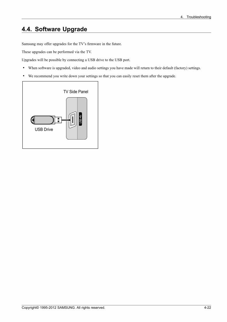
4.4. Software Upgrade
Samsung may offer upgrades for the TV’s firmware in the future.
These upgrades can be performed via the TV.
Upgrades will be possible by connecting a USB drive to the USB port.
• When software is upgraded, video and audio settings you have made will return to their default (factory) settings.
• We recommend you write down your settings so that you can easily reset them after the upgrade.
USB Drive
TV Side Panel
Copyright© 1995-2012 SAMSUNG. All rights reserved. 4-22
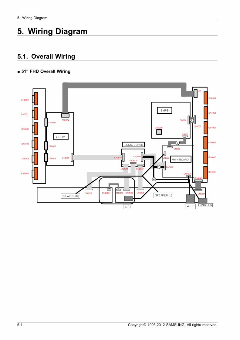
5. Wiring Diagram
5. Wiring Diagram
5.1. Overall Wiring
51" FHD Overall Wiring
CN5500
CN5501
CN5502
CN5503
CN5504
CN5505
CN5000
CN5002
CN5003
CN5004
CN5005
U2
CN4009
CN4008
CN4004
CN4003
CN4002
CN4001
CN2010 CN2001
CN800S
CN801
CN302
CN1602
CN201
CN804
CN4007
CN1201
CN2611CN2509 CN2508 CN2609 CN2603 CN2606
CN2011
CN2013
CN2012
CN4006
¨ || ¡¡ ¥¥
oo ¡¡
¢¢ ¢¢
oo ¡¡
¢¢ ¡¡ oo ww ¡¡ xx ¢¢ ¡¡ oo ww xx
oo ~~ oo ££ ¦¦ ¸|| ¸ ¤¤ ££
2
3
4
1
5-1 Copyright© 1995-2012 SAMSUNG. All rights reserved.

5. Wiring Diagram
60" FHD Overall Wiring
X-Main
Main Board
E-Buffe r
FunctionSpe ake r
Blue tooth
Y-Main
SMP S
CN5401
CN5027
CN5002
CN5003
CN805
CN801
CN4008
CN4006
CN2002
CN1201
CN1
F-Buffe r
CN201
CN5409
CN5410
CN5502
CN5506
CN5507
CN5006
CN5004
CN5005
CN5008
CN5009
CN5007
CN4007
CN4006
CN4005 CN402
CN403
CN404
CN4410
CN4409
CN4408
CN4407
CN4406
CN4405
CN1602
G-Buffe r
CN2004CN2005
CN302
Wifi
2003
CN4005
CN2002 CN2000
CN4004
CN2001
NOTE
The code number of cable (Lead-connector) can be changed, see “Exploded Views and Parts List”.
Copyright© 1995-2012 SAMSUNG. All rights reserved. 5-2
5. Wiring Diagram
Connector Functions
Connector Function
CN201 ↔ CN801 Supply main power and sw_power signal from SMPS to Main Board.
CN1602 ↔ CN2001 The LVDS signal transferred from Main Board to Panel .
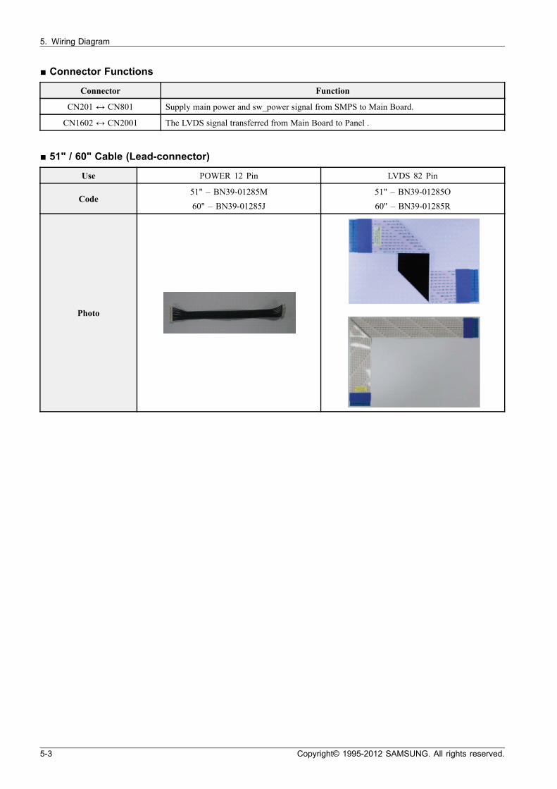
51" / 60" Cable (Lead-connector)
Use POWER 12 Pin LVDS 82 Pin
Code51" – BN39-01285M
60" – BN39-01285J
51" – BN39-01285O
60" – BN39-01285R
Photo
5-3 Copyright© 1995-2012 SAMSUNG. All rights reserved.
5. Wiring Diagram
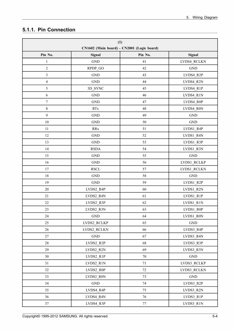
5.1.1. Pin Connection
(1)
CN1602 (Main board) - CN2001 (Logic board)
Pin No. Signal Pin No. Signal
1 GND 41 LVDS4_RCLKN
2 RPDP_GO 42 GND
3 GND 43 LVDS4_R2P
4 GND 44 LVDS4_R2N
5 3D_SYNC 45 LVDS4_R1P
6 GND 46 LVDS4_R1N
7 GND 47 LVDS4_R0P
8 RTx 48 LVDS4_R0N
9 GND 49 GND
10 GND 50 GND
11 RRx 51 LVDS1_R4P
12 GND 52 LVDS1_R4N
13 GND 53 LVDS1_R3P
14 RSDA 54 LVDS1_R3N
15 GND 55 GND
16 GND 56 LVDS1_RCLKP
17 RSCL 57 LVDS1_RCLKN
18 GND 58 GND
19 GND 59 LVDS1_R2P
20 LVDS2_R4P 60 LVDS1_R2N
21 LVDS2_R4N 61 LVDS1_R1P
22 LVDS2_R3P 62 LVDS1_R1N
23 LVDS2_R3N 63 LVDS1_R0P
24 GND 64 LVDS1_R0N
25 LVDS2_RCLKP 65 GND
26 LVDS2_RCLKN 66 LVDS3_R4P
27 GND 67 LVDS3_R4N
28 LVDS2_R2P 68 LVDS3_R3P
29 LVDS2_R2N 69 LVDS3_R3N
30 LVDS2_R1P 70 GND
31 LVDS2_R1N 71 LVDS3_RCLKP
32 LVDS2_R0P 72 LVDS3_RCLKN
33 LVDS2_R0N 73 GND
34 GND 74 LVDS3_R2P
35 LVDS4_R4P 75 LVDS3_R2N
36 LVDS4_R4N 76 LVDS3_R1P
37 LVDS4_R3P 77 LVDS3_R1N
Copyright© 1995-2012 SAMSUNG. All rights reserved. 5-4
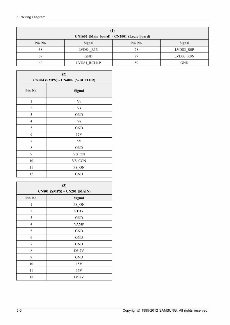
5. Wiring Diagram
(1)
CN1602 (Main board) - CN2001 (Logic board)
Pin No. Signal Pin No. Signal
38 LVDS4_R3N 78 LVDS3_R0P
39 GND 79 LVDS3_R0N
40 LVDS4_RCLKP 80 GND
(2)
CN804 (SMPS) - CN4007 (Y-BUFFER)
Pin No. Signal
1 Vs
2 Vs
3 GND
4 Va
5 GND
6 15V
7 5V
8 GND
9 VS_ON
10 VS_CON
11 PS_ON
12 GND
(3)
CN801 (SMPS) - CN201 (MAIN)
Pin No. Signal
1 PS_ON
2 STBY
3 GND
4 VAMP
5 GND
6 GND
7 GND
8 D5.2V
9 GND
10 15V
11 15V
12 D5.2V
5-5 Copyright© 1995-2012 SAMSUNG. All rights reserved.
5. Wiring Diagram
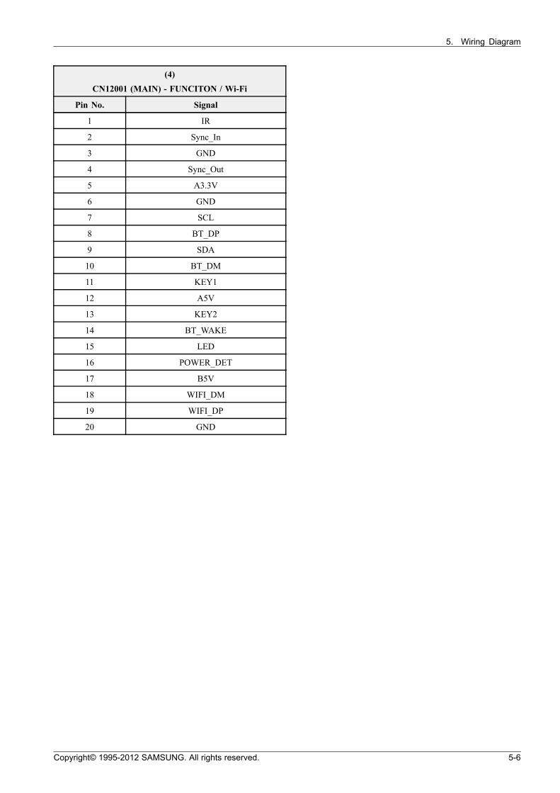
(4)
CN12001 (MAIN) - FUNCITON / Wi-Fi
Pin No. Signal
1 IR
2 Sync_In
3 GND
4 Sync_Out
5 A3.3V
6 GND
7 SCL
8 BT_DP
9 SDA
10 BT_DM
11 KEY1
12 A5V
13 KEY2
14 BT_WAKE
15 LED
16 POWER_DET
17 B5V
18 WIFI_DM
19 WIFI_DP
20 GND
Copyright© 1995-2012 SAMSUNG. All rights reserved. 5-6

GSPN (GLOBAL SERVICE PARTNER NETWORK)
Area Web Site
Europe, MENA,CIS, Africa https://gspn1.samsungcsportal.com
E.Asia, W.Asia,China, Japan https://gspn2.samsungcsportal.com
N.America, S.America https://gspn3.samsungcsportal.com
This Service Manual is a property of Samsung ElectronicsCo.,Ltd.Any unauthorized use of Manual can be punished underapplicable International and/or domestic law.
© 2012 Samsung Electronics Co.,Ltd.All rights reserved.Printed in KoreaCode No.: