Embed Size (px)
Citation preview


2
SAMSUNG ELECTRONICS RESERVES THE RIGHT TO CHANGE PRODUCTS, INFORMATION AND SPECIFICATIONS WITHOUT NOTICE.
Products and specifications discussed herein are for reference purposes only. All information discussed herein is provided on an "AS IS" basis,
without warranties of any kind. This document and all information discussed herein remain the sole and exclusive property of Samsung
Electronics. No license of any patent, copyright, mask work, trademark or any other intellectual property right is granted by one party to the
other party under this document, by implication, estoppel or other-wise. Samsung products are not intended for use in life support, critical
care, medical, safety equipment, or similar applications where product failure could result in loss of life or personal or physical harm, or any
military or defense application, or any governmental procurement to which special terms or provisions may apply. For updates or additional
information about Samsung products, contact your nearest Samsung office. All brand names, trademarks and registered trademarks belong to
their respective owners.

3
Table of Contents ................................................................................................................................................................... 3 List of Figures .......................................................................................................................................................................... 4 List of Tables ........................................................................................................................................................................... 4
Version History ...................................................................................................................................................................................... 5 Introduction ............................................................................................................................................................................ 6 Overview .................................................................................................................................................................................. 7 Linux® Kernel ......................................................................................................................................................................... 8
Linux Kernel Architecture ..................................................................................................................................................................... 8 Booting Process .................................................................................................................................................................... 10
Boot Sequences ................................................................................................................................................................................... 10 U-Boot .................................................................................................................................................................................... 11 RootFS .................................................................................................................................................................................... 13
System .................................................................................................................................................................................................. 13 MultiMedia .......................................................................................................................................................................................... 13 Graphics ............................................................................................................................................................................................... 14 Libraries and Development ............................................................................................................................................................... 14 Connectivity ......................................................................................................................................................................................... 14 Network Protocols .............................................................................................................................................................................. 18
Firmware Update ................................................................................................................................................................. 21 Legal Information ................................................................................................................................................................. 22

4
Figure 1. Basic Hardware Module Architecture ................................................................................................................... 7
Figure 2. Linux Kernel Architecture ....................................................................................................................................... 8
Figure 3. Recovery Boot Sequence ........................................................................................................................................ 9
Figure 4. eMMC Normal Partition Table ............................................................................................................................. 10
Figure 5. eMMC Booting Sequence ..................................................................................................................................... 11
Figure 6. U-Boot Architecture .............................................................................................................................................. 11
Figure 7. U-Boot Sequence .................................................................................................................................................. 12
Figure 8. RootFS Architecture .............................................................................................................................................. 13
Figure 9. MultiMedia Architecture ...................................................................................................................................... 14
Figure 10. Connectivity Architecture ................................................................................................................................... 15
Figure 11. ZigBee Architecture ............................................................................................................................................ 16
Figure 12. Host Application Architecture ........................................................................................................................... 17
Figure 13. User Kernel Space Communication Mechanism ............................................................................................ 18
Figure 14. IoTivity Architecture ............................................................................................................................................ 19
Figure 15. Network Protocol Stack ...................................................................................................................................... 20
Figure 16. Recovery Sequence using SD Card image ....................................................................................................... 21
Table 1. Linux Kernel EOL Structure ...................................................................................................................................... 8
Table 2. Communication Architectures .............................................................................................................................. 18

5
Revision Date Description Maturity
V1.0 October 19, 2016 ARTIK Linux Architecture Guide Release

6
The ARTIK Software Architecture Guide will describe the components that comprise the software architecture that is in place
on the Hardware Module.
The first section will start with a description of the Linux®
kernel and its components. The Linux kernel contains the Kernel
Core, Drivers and BSP packages.
The next section will describe the boot loader U-Boot. The bootloader is responsible for loading the default operating system
that is available on the Hardware Modules during shipping.
After the bootloader the filesystem RootFS will be discussed. The file system contains System, Multi Media, Graphics,
Connectivity, Network Protocols, Libraries and Development Modules.
This document should give the informed Linux developer insight into the inner workings of the Linux software stack residing
on the referenced Hardware Modules.

7
The Fedora Linux operating system used in our Hardware Modules has been developed by the Fedora project. It is based on
the latest version of the open source code base. A new Fedora OS version is released every 6 month. A typical life cycle of any
Fedora OS is about 13 month. The default Fedora distributions available are for Desktop, Server and Cloud implementations.
Our Hardware Modules however use a custom light weight version of Fedora which is built from scratch and only has the
essential packages needed for IoT deployment. Our specialized implementation contains 3 major components:
Linux kernel
U-Boot (Boot Loader)
RootFS (Root File System)
Figure 1 shows the components pictorially. The subsequent sections will describe each component in greater detail.
8
The current Fedora kernel version present on our Hardware Modules is based on the Fedora version 4.1.15. We consolidated
the Linux kernel version and its associated source tree to assure support for our Hardware Modules from one single source.
The hardware used is fully described by its device tree specification file that will be located in the ‘/boot’ partition of the
Hardware Modules.
The basic version rule of the ARTIK kernel is the ‘LTS’ (Long Term Support) kernel. The LTS kernel can support critical bug fixes
such as security patches till it reaches End Of Life. The 4.1 kernel will be maintained till Sep, 2017. Table 1 shows the various
Linux versions with its associated EOL timing.
Version Maintainer Release Project End Of Life
4.4 Greg Kroah-Hartman 2016-01-10 Feb, 2018
4.1 Sasha Levin 2015-06-21 Sep, 2017
3.18 Sasha Levin 2014-12-07 Jan, 2017
3.16 Ben Hutchings 2014-08-03 Apr, 2020
3.14 Greg Kroah-Hartman 2014-03-30 Aug, 2016
3.12 Jiri Slaby 2013-11-03 Jan, 2017
3.10 Willy Tarreau 2013-06-30 Oct, 2017
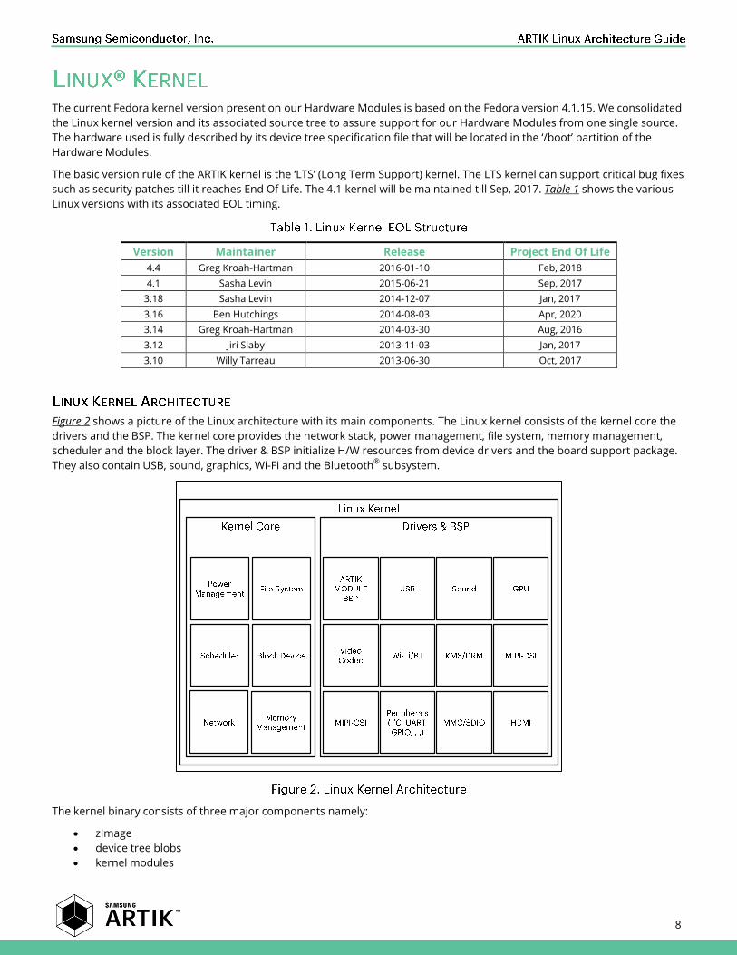
Figure 2 shows a picture of the Linux architecture with its main components. The Linux kernel consists of the kernel core the
drivers and the BSP. The kernel core provides the network stack, power management, file system, memory management,
scheduler and the block layer. The driver & BSP initialize H/W resources from device drivers and the board support package.
They also contain USB, sound, graphics, Wi-Fi and the Bluetooth®
subsystem.
The kernel binary consists of three major components namely:
zImage
device tree blobs
kernel modules

9
The zImage is the compressed kernel binary that will be decompressed during the early stages of the booting process. The
zImage includes prebuilt device drivers.
The device tree blob is the data structure that describes the hardware.
The kernel modules are located in the ‘/lib/modules’ directory. They can be loaded/unloaded into the kernel upon demand.
These kernel modules can also reduce prebuilt kernel binary size and kernel booting time.
The ramdisk can be used when an eMMC recovery from micro sdcard is required see Figure 3. A special ‘sdfuse’ image
contains the image that can be recovered from ramdisk using U-Boot. During normal booting, the ramdisk is not used and
the kernel will mount the Fedora root filesystem directly.
The ‘boot/rootfs’ binaries are stored in eMMC. Figure 3 describes the eMMC disk layout of the supported Hardware Modules.
The Hardware Modules do not use the eMMC boot partition, like the generation-1 ARTIK Modules did, because the boot rom
code cannot load the ‘bl1’ binary from the eMMC boot partition. To circumvent this drawback, the bootloader (‘bl1’,’bl2’ and U-
Boot) is stored in the normal eMMC partition.
The factory information (such as the serial number) is also stored in the eMMC partition. This information can be accessed
using U-Boot. There are three partitions that can be accessed from the Fedora root file system:
The first partition is the FAT partition that stores the kernel binary, device tree blob and the ramdisk image.
The next partition is the mounted ‘/lib/modules’ directory storing kernel loadable modules. These modules will be
loaded on demand from the Fedora root filesystem.
The last partition is “RootFS”. This partition occupies residual storage of the eMMC.

10
Figure 4 shows the partition tables of both a normal boot using the eMMC Partition Table and a boot from the SD Card using
the SD Card Partition Table.
The Partition Tables are split up into a Bootloader Partition and a User Partition. The components that can be found in
subsequent partitions are:
1. Bootloader Partition
a. First Sector : DOS Partition Table.
b. bl1 : The first Bootloader of the Hardware Modules. The content is loaded into SRAM.
c. FIP-loader : This loader loads the FIP Binary.
d. FIP-secure : Secure bootloader that will initialize the secure area.
e. FIP-non secure: U-Boot partition.
2. User Partition
a. ‘/boot’ (Read only): The kernel images such as uImage and tree blobs.
b. ‘/lib/modules’ (Read only) : This partition contains the kernel modules. In addition the root file system will
mount ‘/lib/modules’.
c. ‘/’ (Read/Write) : Root file system.
When the Hardware Module is powered on, the boot rom code ‘bl0’ inside the Hardware Module chip will load the ‘bl1’ binary
from eMMC into on-chip SRAM. This ‘bl1’ binary is located in the first sector offset, once loaded it will start executing ‘bl1’
code. The ‘bl1’ code, amongst other responsibilities, loads the FIP-loader into DRAM and once loaded jumps to the FIP-Loader
code.
The FIP-loader binary loads the ARM®
Trusted Firmware (ATF), located in the FIP-secure partition, and U-Boot, located in the
FIP-non secure partition, into the proper DRAM locations. The FIP-secure binary contains the ATF BL31 used for handling
secure monitor calls and the ATF BL32 for secure OS calls (OPTEE). Once these images are loaded the FIP-loader will jump to
the U-Boot entry point.
The U-Boot loader that loads the kernel binary and the device tree blob from the ‘/boot’ partition, will jump to the Linux
kernel and the kernel core/device drivers will be initialized during kernel booting. Once device drivers are initialized the
RootFS system starts. This system is the first process that will maintain boot daemons such as ‘pulseaudio’ and a Bluetooth
daemon. Figure 5 shows the various steps in a typical (eMMC) booting scenario.

11
The U-Boot is the boot loader that is initiated after the FIP-loader sequence is completed. Its primary purpose is to load the
operating system (in this case Fedora Linux). In addition to loading the Fedora OS, the U-Boot loader takes responsibility for:
System Initialization
Determine the Boot Mode
Firmware Fusing or kernel binary loading
Boot argument control : Control and pass boot parameters from and to the kernel
The U-Boot loader has environment variables that control the booting procedure. It also provides a U-Boot shell and several
helper commands. Figure 6 shows the most important tasks U-Boot is responsible for.
0 1 3841 5889 7168 8192129 769 5921

12
Figure 7 shows the sequence U-Boot will adhere to during the booting process. As an example the first task for U-Boot is to
try to run the ‘bootcmd’ using the U-Boot environment variables. After completion of the ‘bootcmd’ it will follow the flow chart
till the U-Boot will jump to the kernel address.
The ‘factory_info’ (‘run factoryload’) will provide information such as the Ethernet mac address. Once the factory information
is collected the boot arguments will be configured and delivered to the Linux kernel.
Figure 7. U-Boot Sequence

13
The Fedora Linux operating system used in our Hardware Modules is based on a custom light weight version of Fedora, that
we custom build to assure optimal performance in a IoT environment. The RootFS system is an important component of the
OS and it consist of the following components:
System
Multi Media
Graphics
Connectivity
Network Protocol
Libraries and Development
Figure 8 provides a picture, describing the main component in the RootFS system. The subsequent sections will go more in-
depth on the RootFS components mentioned above.
The system group is an essential part of the Fedora RootFS. The ‘systemd’ is an ‘init’ daemon that can run daemons and
services concurrently using initialization order. Each system service can communicate with other services using the ‘dbus’ IPC
mechanism. Fedora is using both the RPM package management system and ‘dnf’ which is new package manager.
The multimedia system of the Hardware Modules consists of both audio and video. Figure 9 shows the Multimedia
architecture implemented on the Hardware Modules.
‘ALSA lib’ is a framework that provides a software API for audio device drivers. The Pulse audio module is based on the ‘ALSA
lib’ for supporting sound. Pulse audio runs a sound server. This is a background process that accepts sound from one or
more sources (processes or capture devices) and redirects this sound into one or more sinks like a sound card a remote
network Pulse audio server or other processes. The system configures ALSA such that it uses a virtual device provided by

14
Pulse audio. Therefore applications using the ‘ALSA lib’ framework will output sound to Pulse audio, which then uses the
‘ALSA lib’ framework itself to access the real sound card.
The video system in the Hardware Modules is based on the ‘gstreamer’ and ’ffmpeg’ libraries and utilities. The ‘gstreamer’
framework is a pipeline-based multimedia framework that links together a wide variety of media processing systems to
complete complex workflows. A user can run a preview, a recording, or he/she can play a video stream using various
‘gstreamer’ plugins. In addition to ‘gstreamer’, ‘ffmpeg’ can be used for similar type of functions. The ‘gstreamer’ framework
does support hardware accelerated video encoding and decoding as a plugin.
All ‘gstreamer’ audio and video communicate using the ‘v4l2’ kernel library. The ‘ffmpeg’ library does not support hardware
acceleration.
The graphics system of the Hardware Modules use a DRM (Direct Rendering Manager) based system called ‘libdrm’. In
addition to the ‘libdrm’ API’s that are provided as the default approach, the graphics system also provides infrastructure for a
‘framebuffer’ approach. The Hardware Modules have ARM®
Mali400TM
-MP4 GPU hardware supporting Mali DDK with
OpenGL®
-ES and X11 EGL acceleration layer.
The ‘glibc’ (GNU-C library) is the base library which can provide C-API functionality and system calls to the kernel. Many of the
libraries such as Multimedia (‘gstreamer’) and Graphics use the ‘glib2’ library that provides advanced data structures for
programming. In addition to GNU-C library support, we also support ‘Nodejs’ and ‘python’ to create scripts and programs.
The Hardware Modules support Wi-Fi, BT/BLE, ZigBee®
and Ethernet connectivity. Figure 10 shows the Connectivity
architecture that is currently present on the Hardware Modules.

15
The Bluetooth library is supported using the ‘BlueZ’ module. The following components are part of the ‘BlueZ’ module:
Bluetooth kernel subsystem core
L2CAP and SCO audio kernel layers
RFCOMM, BNEP, CMTP and HIDP kernel implementations
HCI UART, USB, PCMCIA and virtual device drivers
General Bluetooth and SDP libraries and daemons
Configuration and testing utilities.

16
The ZigBee software consists of the following major components:
NCP (Network Co Processor) image
Application Framework
User Application
Comparing ZigBee to other connectivity mechanisms, ZigBee has no kernel driver support. All device driver roles are
conducted using the NCP. The ZigBee software stack uses the EZSP (EmberZNet Serial Protocol) protocol which is an UART
protocol that communicates between the NCP and the host process. The NCP image includes both the MAC stack and the
ZigBee/ZigBee Pro stack. Figure 11 depicts the ZigBee architecture.
The host application includes the application framework that provides functionality such as:
ZCL (ZigBee Cluster Library)
EZSP communication
User specific application
The user specific application performs control of pre-defined or custom devices adding endpoints and specific roles to these
end points using user code in typical callback functions. Figure 12 depicts the software architecture of the host application.

17

18
The Wi-Fi support that is available on the Hardware Modules consists of a combination of SoC’s that have both kernel and
user mode driver functionality. The firmware that is available on the various SoC’s assure that lower level functionality that
requires real time response is taken care of immediately. The firmware interfaces with the kernel driver module ‘cfg80211’
that is the configuration API for 802.11 devices under Linux. When support for ‘soft mac drivers’ is required, the ‘mac80211’
module is tasked to support such operations. This redistribution of tasks will assure that the SoC firmware can continue to
meet real time requirements. The ‘nl80211’ provides the interface between user space and kernel space. User space
applications can get access using Wi-Fi devices via this library. Figure 13 depicts the architecture required to communicate
using the Wi-Fi user space driver.
The various connectivity architectures (Bluetooth, ZigBee and Wi-Fi) that are in place for the Hardware Modules are
summarized in Table 2.
WPA_SUPLICANT BlueZ EmberNet
Nl80211 HCI EZSP
802.11+802.15.1 802.15.4
The following network protocols that are relevant in IoT space are supported on our Hardware Modules:
IoTivity using the Open Connectivity Foundation Standard
CoAP using libcoap
MQTT using mosquito
mDNS using Avahi
LWM2M using wakaama
The Hardware Modules will protect all data that is transmitted using TLS/DTLS mechanism via OpenSSL or other crypto
libraries.

19
IoTivity is an open source software framework enabling seamless device-to-device connectivity to address the emerging
needs of the Internet of Things. It is based on an implementation of the Open Connectivity Foundation standard. The IoTivity
stack is described in Figure 14.
CoAP is developed in the IETF working group "CoRE", libcoap is a C implementation of the CoAP standard. CoAP is similar to
HTTP, but it is more light-weight specifically geared towards IoT devices.
MQTT is a machine-to-machine (M2M) IoT connectivity protocol. It was designed as an extremely lightweight
publish/subscribe messaging transport system. It is useful for connections with remote locations where a small code
footprint is required. It has three kinds of roles:
Publisher : Publish Message to the Subscriber
Subscriber : Get a Message from the Subscriber
Broker : Manages both Publisher and Subscriber and relays messages
mDNS is a multicast based device discovery service on a local network. It is a ‘zero-configuration’ service, and it enables
discovery without a local name server.
LWM2M is a protocol from the Open Mobile Alliance for M2M or IoT device management.
The Network protocols stack implemented on the Hardware Modules is as described in Figure 15.

20
21
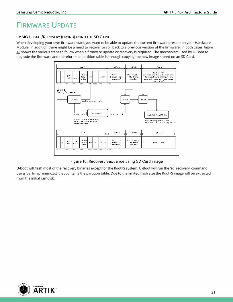
When developing your own firmware stack you want to be able to update the current firmware present on your Hardware
Module. In addition there might be a need to recover or roll back to a previous version of the firmware. In both cases Figure
16 shows the various steps to follow when a firmware update or recovery is required. The mechanism used by U-Boot to
upgrade the firmware and therefore the partition table is through copying the new image stored on an SD Card.
U-Boot will flash most of the recovery binaries except for the RootFS system. U-Boot will run the ‘sd_recovery’ command
using ‘partmap_emmc.txt’ that contains the partition table. Due to the limited flash size the RootFS image will be extracted
from the initial ramdisk.
0 1 3841 5889 7168 8192129 769 5921
0 1 3841 5889 7168 8192129 769 5921

22
INFORMATION IN THIS DOCUMENT IS PROVIDED IN CONNECTION WITH THE SAMSUNG ARTIK™ DEVELOPMENT KIT AND ALL
RELATED PRODUCTS, UPDATES, AND DOCUMENTATION (HEREINAFTER “SAMSUNG PRODUCTS”). NO LICENSE, EXPRESS OR
IMPLIED, BY ESTOPPEL OR OTHERWISE, TO ANY INTELLECTUAL PROPERTY RIGHTS IS GRANTED BY THIS DOCUMENT. THE
LICENSE AND OTHER TERMS AND CONDITIONS RELATED TO YOUR USE OF THE SAMSUNG PRODUCTS ARE GOVERNED
EXCLUSIVELY BY THE SAMSUNG ARTIK™ DEVELOPER LICENSE AGREEMENT THAT YOU AGREED TO WHEN YOU REGISTERED AS
A DEVELOPER TO RECEIVE THE SAMSUNG PRODUCTS. EXCEPT AS PROVIDED IN THE SAMSUNG ARTIK™ DEVELOPER LICENSE
AGREEMENT, SAMSUNG ELECTRONICS CO., LTD. AND ITS AFFILIATES (COLLECTIVELY, “SAMSUNG”) ASSUMES NO LIABILITY
WHATSOEVER, INCLUDING WITHOUT LIMITATION CONSEQUENTIAL OR INCIDENTAL DAMAGES, AND SAMSUNG DISCLAIMS
ANY EXPRESS OR IMPLIED WARRANTY, ARISING OUT OF OR RELATED TO YOUR SALE, APPLICATION AND/OR USE OF
SAMSUNG PRODUCTS INCLUDING LIABILITY OR WARRANTIES RELATED TO FITNESS FOR A PARTICULAR PURPOSE,
MERCHANTABILITY, OR INFRINGEMENT OF ANY PATENT, COPYRIGHT, OR OTHER INTELLECTUAL PROPERTY RIGHT.
SAMSUNG RESERVES THE RIGHT TO CHANGE PRODUCTS, INFORMATION, DOCUMENTATION AND SPECIFICATIONS WITHOUT
NOTICE. THIS INCLUDES MAKING CHANGES TO THIS DOCUMENTATION AT ANY TIME WITHOUT PRIOR NOTICE. THIS
DOCUMENTATION IS PROVIDED FOR REFERENCE PURPOSES ONLY, AND ALL INFORMATION DISCUSSED HEREIN IS PROVIDED
ON AN “AS IS” BASIS, WITHOUT WARRANTIES OF ANY KIND. SAMSUNG ASSUMES NO RESPONSIBILITY FOR POSSIBLE ERRORS
OR OMISSIONS, OR FOR ANY CONSEQUENCES FROM THE USE OF THE DOCUMENTATION CONTAINED HEREIN.
Samsung Products are not intended for use in medical, life support, critical care, safety equipment, or similar applications
where product failure could result in loss of life or personal or physical harm, or any military or defense application, or any
governmental procurement to which special terms or provisions may apply.
This document and all information discussed herein remain the sole and exclusive property of Samsung.
All brand names, trademarks and registered trademarks belong to their respective owners. For updates or
additional information about Samsung ARTIK™, contact the Samsung ARTIK™ team via the Samsung ARTIK™
website at www.artik.io.
Copyright © 2016 Samsung Electronics Co., Ltd.
All rights reserved. No part of this publication may be reproduced, stored in a retrieval system, or transmitted in any form or
by any means, electric or mechanical, by photocopying, recording, or otherwise, without the prior written consent of
Samsung Electronics.