Embed Size (px)
Citation preview
Questa Rock Pile Stability Study SP.6 Page 1
Rev. SP.6 2/28/2009
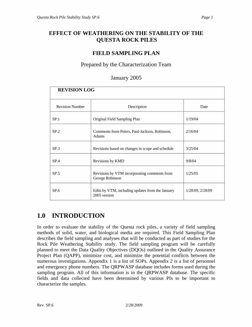
EFFECT OF WEATHERING ON THE STABILITY OF THE QUESTA ROCK PILES
FIELD SAMPLING PLAN
Prepared by the Characterization Team
January 2005
REVISION LOG
Revision Number Description Date
SP.1 Original Field Sampling Plan 1/19/04
SP.2 Comments from Peters, Paul-Jackson, Robinson, Adams
2/16/04
SP.3 Revisions based on changes in scope and schedule 3/25/04
SP.4 Revisions by KMD 9/8/04
SP.5 Revisions by VTM incorporating comments from George Robinson
1/25/05
SP.6 Edits by VTM, including updates from the January 2005 version
1/28/09, 2/28/09
1.0 INTRODUCTION In order to evaluate the stability of the Questa rock piles, a variety of field sampling methods of solid, water, and biological media are required. This Field Sampling Plan describes the field sampling and analyses that will be conducted as part of studies for the Rock Pile Weathering Stability study. The field sampling program will be carefully planned to meet the Data Quality Objectives (DQOs) outlined in the Quality Assurance Project Plan (QAPP), minimize cost, and minimize the potential conflicts between the numerous investigations. Appendix 1 is a list of SOPs. Appendix 2 is a list of personnel and emergency phone numbers. The QRPWASP database includes forms used during the sampling program. All of this information is in the QRPWASP database. The specific fields and data collected have been determined by various PIs to be important to characterize the samples.
Questa Rock Pile Stability Study SP.6 Page 2
Rev. SP.6 2/28/2009
2.0 DATA QUALITY OBJECTIVES The proposed investigation will focus on the following interrelated critical issues: 1) Understanding weathering processes, both at the surface and within the mine-rock
piles 2) Determine the rate at which such weathering processes occur within the rock piles
over time 3) Determining the effect of these processes on the long-term physical stability of the
rock piles.
The key question to be addressed is, “Will the rock piles become gravitationally unstable over time?” The characterization portion of this research project has identified ten Data Quality Objectives, described in the QAPP that must be addressed in order to solve this problem. The field sampling plan specifically addresses nine of the DQOs: 1) Determine how the hydrogeochemistry and water balance dynamics influences rock
pile weathering and stability. 2) Determine how mineralogy, stratigraphy, and internal structure of the Questa rock
piles contribute to weathering and stability. 3) Determine if the sequence of alteration (hypogene and supergene) and weathering
within alteration scars and outcrops in the Questa area provides a basis to predict the effects weathering can have on mine rock material.
4) Determine how weathering of the rock piles affects the geotechnical properties of the rock pile material.
5) Determine if cementation forms in the rock piles and alteration scars and how does the cementation contributes to the stability of the rock piles.
6) Determine how reactive are pyrite and carbonate minerals so representative samples are used in the weathering cells.
7) Determine how much and where the pyrite is in the rock piles and how the pyrite concentration affects the weathering process.
8) Determine if pyrite oxidation, moisture content, and microbe populations affects rock pile weathering and stability.
9) Determine if the geotechnical and geochemical characteristics of the bedrock and alteration scars (foundation) underlying the rock piles influences the rock pile stability.
To meet these DQOs, the Characterization Team will implement this field sampling program in the Goathill North rock piles, other Questa rock piles, alteration scar areas, drill cuttings, and additional adjacent areas. This sampling plan provides the detail sampling procedures to accomplish the work plan.
Questa Rock Pile Stability Study SP.6 Page 3
Rev. SP.6 2/28/2009
3.0 STUDY AREA The Questa molybdenum mine is located on the western slope of the Taos Range of the Sangre de Cristo Mountains, Taos County, northern New Mexico. The current mine is an underground, molybdenum disulfide (“moly”) mine that currently uses a block caving mining method to extract ore. Pit production began in 1969 and ended in 1981, when 81 million tons of ore with an average grade of 0.185 % MoS2 had been processed. During the open pit period of mining ~350 million tons of overburden rock were stripped and deposited onto mountain slopes and into tributary valleys forming the rock piles in this study.
4.0 INVESTIGATION APPROACH The purpose of the Questa Rock Pile Weathering and Stability Project (QRPWASP) is to develop a model to assess and identify the future risk of physical failure of the existing rock piles based on the physical, chemical and mineralogical composition and weathering of the rock at Chevron’s (formerly Molycorp) Questa mine, in Taos County, New Mexico. The key question to be addressed is, “Will the rock piles become gravitationally unstable over time?” Chevron further indicated that the “proposed investigation should focus on 1) understanding weathering processes both at the surface of and within the rock piles, 2) the rate at which such processes occur over time, and 3) the effect or influence of these processes on the overall mass stability of the rock piles.” Weathering can have at least two counter influences on slope stability. First, dissolution of feldspars, biotite and other silicate minerals results in reduction of the silicate mineral grain size and generation of clay minerals, both of which can adversely affect rock-pile stability. Second, iron oxyhydroxides generated by pyrite oxidation, as well as other reaction products, can aid in the cementation of soil grains. Formation of such aggregates will tend to increase rock-pile stability. Generation of water-soluble cements from the oxidation of pyrite also can adversely affect rock-pile stability. Both of these processes appear to be operational at the Questa site and have been observed at many mining sites. Thus the first step in assessing the stability of the Questa rock piles is a complete physical, mineralogical, and chemical characterization of approximately 350 million tons of rock present in nine rock piles at the site utilizing new and existing data. This report addresses the field sampling plan (FSP) required to characterize the rock piles and other materials in the Questa area. The field characterization investigation has been designed to collect data to: • Characterize the overburden bedrock lithologies, including drill core from open pit
deposits and surface outcrops • Characterize the drill core through rock piles • Characterize the rock piles in trenches • Characterize the rock pile samples before and after accelerated humidity cells testing • Characterize the alteration scars, debris aprons, colluvium, and weathering profiles
through the bedrock
Questa Rock Pile Stability Study SP.6 Page 4
Rev. SP.6 2/28/2009
• Characterize the underlying country rocks • Characterize material to be used as cover on the rock piles • Characterize soils and colluvium on the adjacent slopes. The following tasks will be performed: • TASK 1 Literature review (Phase I) • TASK 2 Characterization of overburden bedrock lithologies (Phase I) • TASK 3 Characterization of drill core through rock piles (Phase I) • TASK 4 Characterization of rock piles in test pits/trenches (Phase I) • TASK 5 Characterization of rock pile samples before humidity cells testing (Phase I,
II) • TASK 6 Characterization of alteration scars, debris aprons, colluvium, and
weathering profiles in the bedrock (Phase I, II) • TASK 7 Characterization of underlying country rocks (Phase I) • TASK 13 Stable isotopes of alteration materials(Phase I, II) • TASK 14 3-D Characterization of sulfides using heavy liquid separations, XRD and
geostatistics (Phase I, II) • TASK 16 Drilling program (Phase I, II) (this task was eliminated) • TASK B1.5 Characterization of rock-pile samples after humidity cells testing (Phase
II) • Task B1.1 Characterization of weathering & dev of weathering index & conceptual
model (Phase II) • Task B1.2 Isotope/age dating (Phase II) • Task B1.3 Develop the conceptual and descriptive rock pile model (Phase II) • Task B1.4 Desription of natural analogs, alteration scars, debris flows, river
ferricrestes, other rock piles (Phase II) • Task B 5.1 Geotech-in situ testing (Phase II) • Task McLemore48 Boulder weathering study (Phase II) • Task McLemore49 Hot spots characterization study (Phase II) • Task McLemore Crust study (Phase II) • Task McLemore Megasample geotech testing study (Phase II) Sampling of surface water will occur where encountered. • TASK 11 Hydrological characterization (Phase I - III) • TASK 12 Water stable isotopes (Phase I) Supporting tasks • TASK 8 What will the future climate be? (Phase I - II) • TASK 10, B1.8.1 Spokesperson/Field manager duties (Phase I, II) • TASK 17, B1.8.4 Database design and implementation (Phase I, II) These tasks and supporting activities are described in this field sampling plan (FSP), drilling plans, and supporting SOPs.
Questa Rock Pile Stability Study SP.6 Page 5
Rev. SP.6 2/28/2009
5.0 RESPONSIBILITIES AND QUALIFICATIONS The Characterization Team members will supervise the sampling activities. The Team Leader and Characterization Team will have the overall responsibility for implementing this sampling field plan. They will be responsible for assigning appropriate staff to implement this sampling field plan and for ensuring that the procedures are followed. All personnel performing these procedures are required to have the appropriate health and safety training. In addition, all personnel are required to have a complete understanding of the procedures described within this sampling field plan, and receive specific training regarding these procedures, if necessary. All environmental staff and assay laboratory staff are responsible for reporting deviations from this sampling field plan to the Team Leader. 6.0 PERMIT REQUIREMENTS AND NOTIFICATION Chevron and its drilling contractor(s) are responsible for securing all necessary permits and meeting all local, state, and federal regulations applying to all sampling and drilling activities, including, but not limited to, site access, waste disposal, operator health and safety, etc.
7.0 LIST OF EQUIPMENT See SOPs for list of equipment. 8.0 RELATED STANDARD OPERATING PROCEDURES The procedures set forth in this plan are intended for use with the SOPs listed in Appendix 1.
9.0 FIELD ACTIVITIES This section describes field activities that will be performed for the Molycorp Weathering Project and consist of the following activities: • Premobilization and site reconnaissance • Surveying • Geophysical surveying • Geological mapping of the rock piles • Characterization sampling • Drilling • Ground water sampling
Questa Rock Pile Stability Study SP.6 Page 6
Rev. SP.6 2/28/2009
• Ground water monitoring well installation and development • Microbe sampling • Decontamination • Quality control and quality assurance procedures Instructions for implementing these tasks are given in standard operating procedures (SOPs), which are included with this FSP. Field audits, as described in the quality assurance project plan (QAPP), will be performed to verify that approved methods and procedures are followed during the field investigation. Any identified deviations from this FSP or SOPs will be documented and the Team Leader and Principle Investigators will be informed. Procedures for corrective action are described in the QAPP. Chevron or their contractors will be responsible for containing and disposal of all wastes incurred during the field investigation as well as procedures for utility clearance. Premobilization and site reconnaissance One or more reconnaissance trips may be needed to identify sampling sites and address any potential safety issues. All trips to Questa must be scheduled with Virginia McLemore and Bruce Walker. Sample Site Selection and Marking Selected sample locations will be marked with flagging tape or paint. Sample sites will be selected on the basis of location of specific lithologic sample needed and safe access. Photographs will be taken (SOP 4). Surveying Conventional land and GPS survey techniques will be used to survey drill hole locations and elevations; surface water and sediment sampling locations; surface soil and biological sample locations; geophysical and sampling grid locations, elevations, and orientations; utility clearance (as applicable); and other surface and subsurface features. Chevron Mining Inc. will be responsible for all surveying other than GPS locations of samples. SOP 3 describes the procedures for GPS surveying.
Geophysical surveying SOP 23 describes the procedures for surface geophysical surveys. Geological mapping and modeling of the rock piles The first step in geological mapping of the rock piles will identify existing data and maps. The maps will be incorporated into GIS as separate layers and other graphic programs as needed. The following is a partial list of GIS layers and models needed: • Geology (Geologic Mapping Plan) • Current topography • Original topography • Remote sensing (Peters, Hauff) • AVRIS • Underground workings
Questa Rock Pile Stability Study SP.6 Page 7
Rev. SP.6 2/28/2009
• Drill holes, test pits/trenches locations • Sample locations (proposed and already collected) • Photograph locations • Surface and borehole geophysical profiles • Pyrite reserve model will provide a view of the pyrite distribution within the rock piles
(SOP 34) (by Brimhall) • Stratigraphic columns of drill holes and test pits/trenches (by Characterization team) • Cross sections and longitudinal sections of the rock piles (by Characterization team) • Geologic models of the rock pile (mineralogy, internal structure, stratigraphy) (by
Characterization team) • Hydrologic and hydrostratigraphic models to investigate hydrologic processes within
the framework of our geologic models (by Characterization team) • Heat flow/temperature/two-phase water flow models will help determine the degree
to which heat can drive liquid and vapor-phase water flow within the piles and identify hot spots within the piles (by Reiter)
• Infiltration models will aid in estimating the range of liquid-phase water inflows to the rock piles using estimated, measured, or simulated climatologic inputs.
• A water balance model for each rock pile is critical to determining rock pile stability because it will predict how water content and matric potential are distributed within the pile as well as how they will evolve dynamically in time. Applying different future climate conditions to the water balance model will produce the matric potential distributions needed by the geotechnical models to predict long-term stability.
• Climatic models (by Characterization team) The geologic mapping plan is developed and available SAMPLING Different sampling strategies will be employed based upon the purpose of each sampling task. Field geologists with experience in the regional stratigraphy and in the recognition of altered and weathered rocks perform the sampling. The types of samples to be collected include: • Characterization sampling (rock outcrops, soil, other) (SOP 5)
• Criteria for selection: weathering cells tests, alteration assemblages, different cementation, lithologies, mineral zonation, different stages of weathering
• Alteration scars (SOP 5) • Criteria for selection: lithologies, degree of alteration, specific minerals for
stable isotopes and dating • Soil samples of areas that represent what we want the final slopes to look like in terms of vegetation cover • Samples to go into the humidity cells (SOP 5) (samples to Univ of Utah)
• Criteria for selection: lithology, different stages of weathering, pyrite content, sulfur content, location is accessible; samples of the proposed cover material for the rock piles
• Samples after humidity cells testing (samples from Univ of Utah) • Drill core and cuttings of the deposit before being placed into the rock piles (SOP 5)
Questa Rock Pile Stability Study SP.6 Page 8
Rev. SP.6 2/28/2009
• Drill core and cuttings of the rock piles (SOP 5) • Test pits, trenches, and high wall select and composite samples (SOP 5) • Rock pile surface, channel, and transect sampling (SOP 5) • Drill core and cuttings of the rocks underlying the rock piles (SOP 5) • Sampling for the Remaining Pyrite Model (SOP 34) (samples to Brimhall) • Surface water and seep sampling (SOP 15)
• Criteria for selection: as available • Samples for pore water measurements (SOP 39) • Snow and rain (SOP 47)
• Criteria for selection: as available • Water vapor (SOP 46) and other gases • Microbe sampling (SOP 37)
• Criteria for collecting from test pits/trenches: increased temperature as determined during drilling using a standard thermometer
• Criteria for collecting: include selected samples of all types of samples for microbe examination
• Samples for geotechnical testing Characterization sampling Characterization sampling is required to identify samples that go into the humidity cells as well as characterize the overburden, rock piles, underlying rocks, and other country rocks. All of the major lithologic units using outcrop localities, drill core, rock piles, and test pits/trenches will be sampled and will include different degrees of alteration and weathering, alteration assemblages and mineral zonation. SOP 5 describes the procedures for sampling outcrops, rock piles, and drill core (solid samples). SOP 6 describes the procedures for sampling during the drilling program. SOP 9 describes the procedures for sampling test pits, trenches, and high walls. The exploratory stage of characterization will occur first, primarily to determine which samples are selected for humidity cell tests. This stage also will provide samples for characterization of rocks that went into the rock piles, rocks that underlie the rock piles, alteration scars, and debris flows. Samples of all of the major lithologic units as well as alteration assemblages and different stages of weathering will be collected from outcrop localities, open pit, drill core and cuttings, rock piles, test pits, and high walls. Additional samples will be collected from throughout the rock piles as needed. A standardized protocol will be followed after each sample is taken (SOP 2). At each site, a select, grab, or bulk sample of rock or other material is collected for petrographic study and geochemical analyses that is representative of the DQO being addressed. A hand specimen also is collected for thin section and archived. Each sample is collected in a separate bag, assigned a unique number (field_id), and logged on a field description form (Appendix 3). Selected sample sites are marked in the field and a digital photograph (SOP 4) is taken at most localities. Photographs provide visual record of sample site; the photograph form identifies site specifics, provides basic location and other data about the photograph (SOP 4). Location information by GPS, type of sample, and field and
Questa Rock Pile Stability Study SP.6 Page 9
Rev. SP.6 2/28/2009
laboratory petrographic descriptions will be collected. Each sample will be clearly identified. Geologic observations are recorded on the field description form and each site is located on a map (SOP 5). A global positioning system (GPS) reading is recorded as well (SOP 3). Hand specimen description provides a record of what was collected, aids in petrographic description, and provides information on sample for the labs (high S may be treated differently then low S). The hand specimen description is the preliminary data required to determine what samples need specific detailed analyses to meet the DQOs. NMBGMR will archive all samples for potential future studies. Reflectance spectroscopy analyses in the field (SOP 41) provide on site mineral identification and helps in selecting samples for specific purposes to meet the DQOs (jarosite is needed for dating, field identify clay minerals and cements for easier sampling). Samples are selected in the field by visual examination in field that require immediate mineral identification. The samples are transported from the field to NMBGMR (SOP 36), where each sample is prepared for analyses (SOP 8). Samples will be cut and chips will be sent for preparation of polished thin sections. The prepared samples are then sent to a laboratory for analyses. NMBGMR standards are submitted blind to the commercial laboratory with each sample batch to assure analytical quality. Petrographic analysis and mineral identification are important in differentiating various rock units, determining rank and intensity of alteration, determining chemistry of alternating fluids, describing cementation, and determination of paragenesis of mineralization, alteration, and cementation. Alteration rank is based upon the mineral assemblages, which infers temperature, pressure, and permeability conditions at the time of formation. A weathering index will be defined and used to define the different stages of weathering. Petrography will be performed using standard petrographic and reflected ore microscopy techniques. Mineral concentrations will be estimated using standard charts and data. Estimates of both primary and alteration minerals will be determined, cementation described, and the alteration intensity will be determined from the concentration of alteration minerals. Forms are in Appendix 3. Digital photographs will be taken (SOP 4). Simple shear box tests will be performed on many samples to determine the strength of the material. Characterization Sampling Procedure 1. Collect samples of all of the major lithologic units using outcrop localities, drill core,
rock piles, test pits/trenches following the guidelines outlined for each task or specific sampling protocol, depending on the purpose of collecting the sample (SOP 5, 6, 9, 37). The numbering system we will use will be 3 letters that represent the mine feature (SSW)-3 initials of sampler-0001 sequentially. For example SSW-HRS-0001 is the sample #1 collected by Heather R. Shannon from the Sugar Shack West rock pile. If at all possible, collect a sample of the adjacent soil derived from the rock outcrop so that shear stength and other geotech tests can be performed. Samples of weathering profiles should be collected where ever possible to provide differences in weathering of the same material.
Questa Rock Pile Stability Study SP.6 Page 10
Rev. SP.6 2/28/2009
2. Record geologic observations on the sample description form. Fill out a chain of custody and request for analysis form (SOP 2).
3. Record site description on the sample description form. 4. Locate each site on a topographic map and take a GPS reading (NAD 27, UTM) and
enter on the sample description form (SOP 3). 5. Photograph sample site (information recorded on photograph form, SOP 4). The
numbering system for the photograph will be the field identification number 0001 sequentially. For example SSW-HRS-0001-F001 is the photograph #1 that HRS took at sample site #1. Photographs will be taken at highest resolution as jpeg or tif files and stored in separate folders corresponding to their image type.
6. Archive hand sample or split of unconsolidated sample prior to sample preparation. 7. All data are entered into the project Access database Procedure for collecting samples for humidity cells 1. Samples will be selected on the basis of representative lithology, variable pyrite
concentrations, different alteration assemblages and intensity, and different stages of weathering.
2. Twenty to 400 pounds of rock are collected, including some fine material. 3. Samples are shipped to Univ of Utah for processing and weathering cells testing and
to Univ of Utah for microbial analyses. 4. Univ of Utah will ship a split of the processed material to New Mexico Tech for
characterization. Procedure for collecting undisturbed samples See appropriate SOPs for sampling of undisturbed materials for hydrologic and geotechnical tests. Drilling and trenching Subsurface data provides the third dimension to this study. Diamond drill-core and cuttings will be examined and logged. Trenches, test pits, and high walls will be examined. A binocular microscope and/or hand lens will be used in examining the samples. Samples will be obtained for thin section preparation and geochemical analyses. A summary of pertinent drill core data will be provided. Drill holes, trenches, test pits, and highwalls are located on Chevron maps. Digital photographs will be taken. SOP 5 describes the procedures for sampling outcrops, rock piles, and drill core (solid samples). SOP 6 describes the procedures for sampling during the drilling program (also see drilling plan). SOP 9 describes the procedures for sampling trenches, test pits, and highwalls. Selected samples sent to Univ of Utah for microbial analyses. Surface water and seep sampling Should any surface water or seeps be encountered in or near the rock piles, sampling could occur according to SOP 15. Selected samples sent to Univ of Utah for microbial analyses. Microbe sampling
Questa Rock Pile Stability Study SP.6 Page 11
Rev. SP.6 2/28/2009
SOP 18, 37 describes the procedures for microbe sampling. All samples collected for microbe studies must have a split sent for full chemical and mineralogical analyses. Decontamination SOP 7 describes the procedures for decontamination of field equipment. 10.0 ANALYTICAL ACTIVITIES This section describes analytical activities that will be performed for the Molycorp Weathering Project and consist of the following activities: • Sample preparation • Bulk mineral identification • Clay mineral analyses • Particle size determination • Leaching analysis • Geochemical and statistical analyses • Shear box tests • Decontamination • Analytical measurements • Quality control and quality assurance procedures Sample preparation and analysis (solid) 1. Solid samples crushed for chemical analyses and cut for thin sections (information
recorded on sample preparation form, SOP 8). 2. Polished thin sections of selected samples will be prepared by NMIMT lab and
examined for mineralogy (petrographic description form, SOP 24). 3. Photograph taken of thin sections (information recorded on photograph form, SOP
4). 4. Selected thin sections and other samples for electron microprobe study (SOP 26). 5. Samples analyzed for bulk mineralogy using XRD and recorded in mineralogy table
(SOP 27). 6. Selected samples analyzed for clay minerals and recorded in clay mineralogy table
(SOP 29). 7. Selected samples leached for DI leach for soluble ions (soluble mineralogy, SOP 38). 8. Selected samples broken into size fractions and chemistry determined on individual
size fractions (SOP 33). Bulk mineral identification by XRD Bulk mineral identification can be used to identify minerals present in quantities greater than approximately 3%. Altered, unaltered, and mineralized samples, including select samples of cement, will be powdered and analyzed by X-ray diffraction (XRD) at NMSU using pressed powder slides, as described in SOP 27. XRD analyses will be determined using a Rigaku XRD unit with CuKa at 50 kV and 25 mA. Weathered mine rock piles typically contain some amount of amorphous material that can not be identified by XRD (Smith et al., 2000), but by integrating electron microprobe and geochemical data this material can be characterized. This amorphous material typically contains metals that can
Questa Rock Pile Stability Study SP.6 Page 12
Rev. SP.6 2/28/2009
be released into the water and also may form clay minerals. This amorphous material in some cases acts as a cement. A random sample mount is used for a sample split after it has been ground to pass a 60-mesh sieve. With greater care, the sensitivity can be lowered to identify minerals in the ±2 wt.% range. However, this depends on the character of the x-ray reflections. Well-crystallized material is more easily identified than poorly crystalline material. Quartz is commonly the dominant mineral present in New Mexico sediments because these sediments consist of mostly of structural or detrital mineral grains. Cementing agents (clay minerals, dolomite, and calcite) are present in smaller amounts. The identification is by principal reflections. In most samples from a given area or deposit, standard mineralogy is quickly established. After an initial period of mineral identification using all available reflections, only the principal reflections are used to compare ratios for semi-quantitative analyses. However, all diffractograms are scanned to see if minerals other than the standard suite are present. If unknowns other than very minor ones are identified, a computer program called JADE is available for mineral identification. If more accuracy that our normal semi-quantitative method is necessary, “spikes” of known quantities of the monomineralic materials are used with samples to establish the amount present. Clay mineral analyses The identification of clay minerals is commonly done with oriented <2 μm fraction of samples, as described in SOP 29. A split of the sample is placed in distilled water, stirred and allowed to settle. After a specified time interval, a portion of the <2μm fraction is removed from the top of the suspension, placed on a glass slide, and dried. The resulting coat consists of the oriented clay-size fraction of the sample. The slide is examined with x-ray diffraction from 2 to 40° 2θ, soaked in an ethylene glycol atmosphere and examined again with x-ray diffraction, and heated to 350°C for 30 minutes and examined again with diffraction. The results are reported as parts in ten of the following clay mineral groups: kaolinite, illite, chlorite, vermiculite, smectite, and I/S (mixed-layer illite-smectite). The mineralogy of the small amounts of non-clay minerals is determined as well. The common non-clay minerals are calcite, dolomite, gypsum, orthoclase, plagioclase, and quartz. When only small amounts of the feldspars are present, it may not be possible to distinguish between orthoclase and plagioclase. Particle size determination A split (preferred 500 gr, but can use 250 gr minimum) is taken of the original sample for particle size analysis, as described in SOP 33. It is then dried and weighed. The sand-and-larger-size material is first separated from the split by washing the split through a 230-mesh screen. The sand+ fraction remains on the screen. It is dried and weighed. The silt-and-clay mixture passing through the screen is separated into clay- and silt-clay suspensions by standard settle techniques. The clay suspension is weighed and the weights of the sand+ and clay fractions are used to calculate the silt fraction. Results accurate to +2%. If requested, the sand fraction can be separated from coarser material. If
Questa Rock Pile Stability Study SP.6 Page 13
Rev. SP.6 2/28/2009
a greater number of size splits is needed, other labs at the Bureau can be used to determine these values. Selected samples will be submitted for particle size analyses in order for bulk mineral analyses (XRD) and chemical analyses (XRF, ICP) to determine the mineralogy of the size fractions. Several 1000 gr of material will be required in order to provide enough material for analyses on each size fraction. Chemical analyses Chemical analyses of solids (ICP, XRF, other, SOP 30, 31, 28) provide detailed concentrations of abundance of specific elements that directly relate to mineralogy and water quality and are required for selecting samples for humidity cells (data goes to Trujillo, Lapakko), and for developing geotechnical models (data goes to Wilson), weathering models (data goes to Trujillo), and geologic (mineralogy, stratigraphy, internal structure) models of the rock piles. Chemical analyses of water samples provide in formation on pore water chemistry and relates to the sequence of alteration SOP 30, 31). 1. Solid samples analyzed for major and trace elements using XRF, ICP, and other
methods (XRF— SiO2, TiO2, Al2O3, Fe2O3, MnO, CaO, NaO, K2O, P2O5, LOI, As, Ba, Cu, Pb, Zn, Mo, Cr, Co, Ni, V, Ga, Nb, Sc, Rb, Cs, Zr, Hf, Y, Ta, Th, U; ICP—Au, Ag, Sb, As, Se, Te, Ba, Sn, Bi, Tl, Cu, Pb, Zn, Cd, Mo, Cr, Co, Ni, V, Be, Sc, Rb, Cs, Zr, Th, U, La, Ce, Sm, Eu, Tb, Yb, Lu; other methods—SO4, S, CO3, F, Hg) (SOP 11, 28, 30, 31, 35)
2. Water samples analyzed for major and trace elements using ICP and other methods— CO3
-2 , HCO3-1, Cl-1, SO4
-2, NO3-1, PO4
-3, Na+1, K+1, Mg+2, Ca+2, Al, As, Ba, Cd, Cr, Co, B, Fe, Pb, Li, Mn, Hg, Mo, Ni, Se, Si, Ag, Sr, Th, U, pH, Conductivity, Total Dissolved Solids (TDS), Total Suspended Solids (TSS) (SOP 30, 31)
Paste pH and conductivity Paste pH and paste conductivity (SOP 11) are used to evaluate the geochemical behavior of mine rock materials subject to weathering under field conditions and to estimate the pH and conductivity of the pore water resulting from dissolution of secondary mineral phases on the surfaces of oxidized rock particles. Leaching analysis This test, described in SOP 38, is designed to extract soluble carbonates and sulfates from minerals without attacking insoluble minerals such as silicates, and in particular, clay minerals. A simple washing or leaching of the sample is performed using deionized water. The leachate is analyzed for major and trace elements using the ICP. The carbonates and sulfates act principally as cementing agents as in New Mexico sediments, but also can be present as structural particles as well. Electron microbe Electron microprobe analyses (SOP 26) provide mineral identification, specific mineral chemistry, relationships between the minerals, provide information on how minerals are
Questa Rock Pile Stability Study SP.6 Page 14
Rev. SP.6 2/28/2009
altering, and what new minerals forming at a microscopic level. Probe analysis can identify rims around sulfide minerals that could inhibit alteration of the mineral.
Criteria for selection: after petrographic analysis, clay mineralogy, DI leach, required to answer specific questions concerning microscopic characteristics
Stable isotopes Stable isotopes of solid minerals (SOP 25) are important in understanding the origin of alteration and sequence of alteration and weathering with time. Analyzing the chemistry (SOP 30, 31) and stable isotope concentrations (SOP 25) of precipitation, snow, pore water, and exfluent (seepage) will constrain water flow models and provide calibration data.
Criteria for selection: occurrence of specific minerals Stable isotope analyses of liquid and vapor-phase water provide a reality check on models of water and heat transport through the rock piles by revealing the amount of evaporation. Argon/argon age determination Argon/argon age determinations (SOP 44) are important in understanding the origin of alteration and sequence of alteration and weathering with time.
Criteria for selection: occurrence of specific datable minerals Porosity and bulk density Porosity (SOP 42) and bulk density (SOP 32, 65, 70) are needed to estimate the critical hydraulic relationships (i.e., moisture retention relationship, SOP 45, and the hydraulic conductivity – moisture content relationship), and to model water transport and rock pile stability. Moisture content Mapping in situ moisture content describes a point-in-time distribution of water within the pile. It also identifies which hydrostratigraphic units are more likely to reach the near-saturation water contents necessary to induce movement. In situ moisture content measurements are inputs and/or calibration data for models of water flow (data to Wilson), reactive transport (data to Trujillo), and mechanical stability (data to Wilson, Fredlund). Determining the moisture retention (SOP 45) and hydraulic conductivity – moisture content relationships for selected hydrostratigraphic units are essential inputs for modeling water flow, reactive transport (data to Trujillo), and mechanical stability (data to Wilson, Fredlund). Matric potential Monitoring in situ matric potential values with tensiometers and thermal conductivity sensors describes the capillary forces driving water through the piles. The time evolution of matric potentials at selected locations will belp determine the overall dynamic water balance within the rock pile. Knowledge of matric potential distributions is essential for predicting water flow through the pile and therefore the pile’s mechanical stability.
Questa Rock Pile Stability Study SP.6 Page 15
Rev. SP.6 2/28/2009
Measured matric potentials are critical inputs and/or calibration data for modeling water flow, reactive transport (data to Trujillo), and mechanical stability (data to Wilson, Fredlund). Climatic data Collecting historic and on-site climate data such as precipitation, temperature, evaporation, snow accumulation, and wind speed are necessary inputs for all models involving water flow and understanding historic climatic patterns needed to predict future patterns. Geochemical and statistical analyses Statistical determinations of chemical analyses of samples collected for this study and of data sets provided by Molycorp and their consultants are important in summarizing the data and ultimately in interpreting the significance of each data set. Each data set will be statistically analyzed separately using appropriate computer programs, such as WinStat. Means, standard deviations, and correlation coefficients will be determined where appropriate and factor analyses and discriminate analyses will be employed. Histograms, scatter plots, and other plots of the data will be performed to determine trends. Petrologic calculations of major-element analyses of unaltered and altered rock samples will be obtained. Shear box tests Simple shear box tests will be conducted on fine grain size material to determine the strength of the material (SOP 50). Decontamination SOP 7 describes the procedures for decontamination of field equipment. 11.0 QUALITY CONTROL AND QUALITY ASSURANCE
PROCEDURES Procedure—A standardized protocol will be followed after each sample is taken and chain of custody and request for analyses will be completed. Location data by GPS, type of sample, and field and laboratory petrographic descriptions will be collected. Each sample will be clearly identified and a chain of custody process will be followed to assure that all samples were transported to the laboratory, analyzed, and results sent back to NMBGMR. The samples will be transported from the field to NMBMMR, where each sample will be crushed in jaw crushers and pulverized by tungsten-carbide disc grinders to a grain size of <35 μm. Each sample will be homogenized at each crushing step by cone and quarter method. The samples will be sent to a laboratory for analyses. For each batch of 10 samples, 1 set of duplicate samples with different sample_id numbers will be run. For each batch of 25 samples, 1 set of triplicate samples with different sample_id numbers will be run. NMBGMR internal (Capulin, rhyolite, basalt, sand, Capulin rock pile) and commercial certified standards will be submitted blind to the
Questa Rock Pile Stability Study SP.6 Page 16
Rev. SP.6 2/28/2009
laboratory with each sample batch of 25 samples to assure analytical quality. NMBGMR will archive a split of all samples for future studies. Accuracy and precision of data—The accuracy of the data is how close the measured value is to the true value. Analyzing certified standards as unknown samples and comparing with known certified values monitors accuracy. The precision of an analysis is the repeatability of a measurement. Precision is monitored by multiple analyses of many sample duplicates and internal standards. Estimates of accuracy and precision will be determined. Errors due to accuracy will be determined by multiple analyses of commercial standards for which accepted values are known. Errors due to precision will be determined by multiple analyses of selected sample splits, as well as multiple analyses of standard samples. There are numerous reasons why duplicate samples and/standards do not always agree. Some samples, such as rhyolite and andesite, grind into powder more easily than other samples, such as stream-sediment and rock pile samples. Fusion techniques required for XRF analyses vary from lab to lab and may also differ between different personnel that could result in variations between sample pairs. Analytical error is higher for analyses with concentrations close to the detection limit. In addition, mine samples and alluvium, such as the Capulin standard (CAP-MLJ-0001), are very heterogeneous and difficult to completely homogenize. Another problem encountered with mine samples, is the variability of sample collection. Only trained geologists will collect the Molycorp samples using the exact procedures to avoid variations between sample collectors. In addition, three samples will be collected at two separate sites by one sampler to estimate sample heterogeneity and assigned different field_id numbers. At one site, two or three different people will collect a sample and assign a different field_id numbers to estimate sample collection variability. 12.0 DATA MANAGEMENT Data for the Rock Pile Weathering study will be obtained from a combination of sources, including field and laboratory measurements. The process of collecting and managing data is a coordinated effort (described in SOP 1) and will be conducted by project staff and laboratories working closely together. Laboratory data will be provided, when appropriate, in electronic form, in addition to the required hard-copy analytical data package. Data quality will be examined (SOP 1) before results are presented or used in subsequent activities. The laboratory will confirm sample receipt, sample condition, and required analyses. All pertinent information about each sample will be recorded.
13.0 SAMPLING SCHEDULE August 12-13, 2003 Examination of Sugar Shack West and collection of samples to
calibrate thermal camera (McLemore, Shannon) September 12, 2003 Examination of rock piles, preliminary geophysical survey
(McLemore, Dunbar, Gomez, Heizler, Hendickx, Sigda, Shannon) October 22, 2003 Examination and sampling of alteration scars (Campbell, Lueth)
Questa Rock Pile Stability Study SP.6 Page 17
Rev. SP.6 2/28/2009
December 8-9, 2003 Logging and sampling of Sonic drill holes S-1, S-2 (McLemore, Gomez, Raugust, Tachie-Menson, Guiterez, Brimhall, Hoffman, Vargas)
January 7-12, 2004 Logging and sampling of SI holes, holes of pit deposit before mining, sonic holes, and collection of reports (McLemore, Gomez, Raugust, Tachie-Menson, Guiterez, Shannon, Sigda, Campbell, Lueth, Mullen, Krueger)
January 29-February 2, 2004 determination of characterization sample location, installing precipitation collectors (McLemore)
January-June 2004 Characterization sampling for determining which samples are submitted for weathering cells tests
January-June 2004 Logging and sampling of pre-existing drill core of the overburden before it was mined
February-June 2004 Sampling alteration scars for stable isotope analysis February-June 2004 Geophysical surveying May-October 2004 Characterize Goat Hill North rock pile January-Febuary 2005 Characterize Goat Hill North rock pile March–September 2005 characterization and drill core sampling ANALYSES SCHEDULE As samples are collected, sample preparation and analyses will occur as indicated on the chain of custody and request for analyses. The ICP-OES laboratory will not be available until February 2005. 14.0 TYPES, NUMBERS, AND LOCATIONS OF SAMPLES
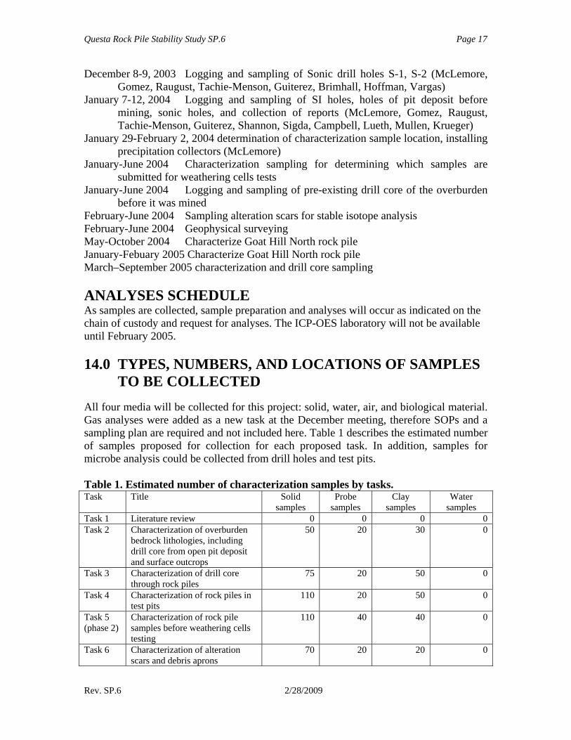
TO BE COLLECTED All four media will be collected for this project: solid, water, air, and biological material. Gas analyses were added as a new task at the December meeting, therefore SOPs and a sampling plan are required and not included here. Table 1 describes the estimated number of samples proposed for collection for each proposed task. In addition, samples for microbe analysis could be collected from drill holes and test pits. Table 1. Estimated number of characterization samples by tasks. Task Title Solid
samples Probe
samples Clay
samples Water
samples Task 1 Literature review 0 0 0 0 Task 2 Characterization of overburden
bedrock lithologies, including drill core from open pit deposit and surface outcrops
50 20 30 0
Task 3 Characterization of drill core through rock piles
75 20 50 0
Task 4 Characterization of rock piles in test pits
110 20 50 0
Task 5 (phase 2)
Characterization of rock pile samples before weathering cells testing
110 40 40 0
Task 6 Characterization of alteration scars and debris aprons
70 20 20 0
Questa Rock Pile Stability Study SP.6 Page 18
Rev. SP.6 2/28/2009
Task Title Solid samples
Probe samples
Clay samples
Water samples
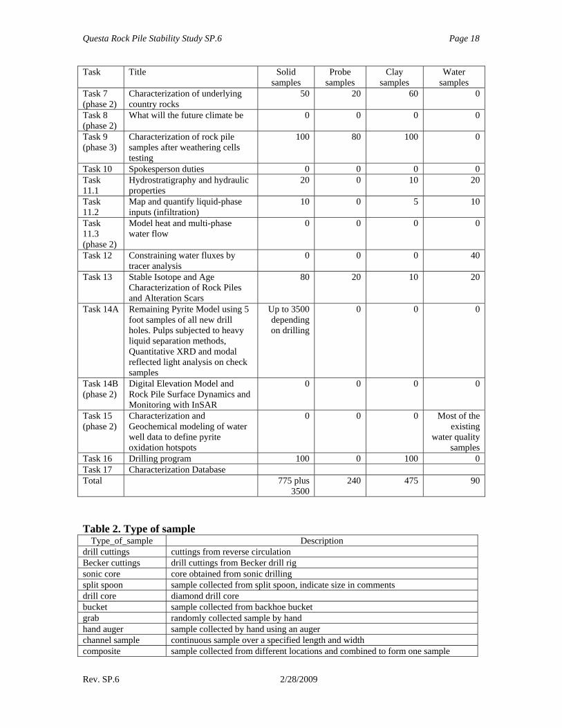
Task 7 (phase 2)
Characterization of underlying country rocks
50 20 60 0
Task 8 (phase 2)
What will the future climate be 0 0 0 0
Task 9 (phase 3)
Characterization of rock pile samples after weathering cells testing
100 80 100 0
Task 10 Spokesperson duties 0 0 0 0 Task 11.1
Hydrostratigraphy and hydraulic properties
20 0 10 20
Task 11.2
Map and quantify liquid-phase inputs (infiltration)
10 0 5 10
Task 11.3 (phase 2)
Model heat and multi-phase water flow
0 0 0 0
Task 12 Constraining water fluxes by tracer analysis
0 0 0 40
Task 13 Stable Isotope and Age Characterization of Rock Piles and Alteration Scars
80 20 10 20
Task 14A Remaining Pyrite Model using 5 foot samples of all new drill holes. Pulps subjected to heavy liquid separation methods, Quantitative XRD and modal reflected light analysis on check samples
Up to 3500 depending on drilling
0 0 0
Task 14B (phase 2)
Digital Elevation Model and Rock Pile Surface Dynamics and Monitoring with InSAR
0 0 0 0
Task 15 (phase 2)
Characterization and Geochemical modeling of water well data to define pyrite oxidation hotspots
0 0 0 Most of the existing
water quality samples
Task 16 Drilling program 100 0 100 0 Task 17 Characterization Database Total 775 plus
3500 240 475 90
Table 2. Type of sample
Type_of_sample Description drill cuttings cuttings from reverse circulation Becker cuttings drill cuttings from Becker drill rig sonic core core obtained from sonic drilling split spoon sample collected from split spoon, indicate size in comments drill core diamond drill core bucket sample collected from backhoe bucket grab randomly collected sample by hand hand auger sample collected by hand using an auger channel sample continuous sample over a specified length and width composite sample collected from different locations and combined to form one sample
Questa Rock Pile Stability Study SP.6 Page 19
Rev. SP.6 2/28/2009
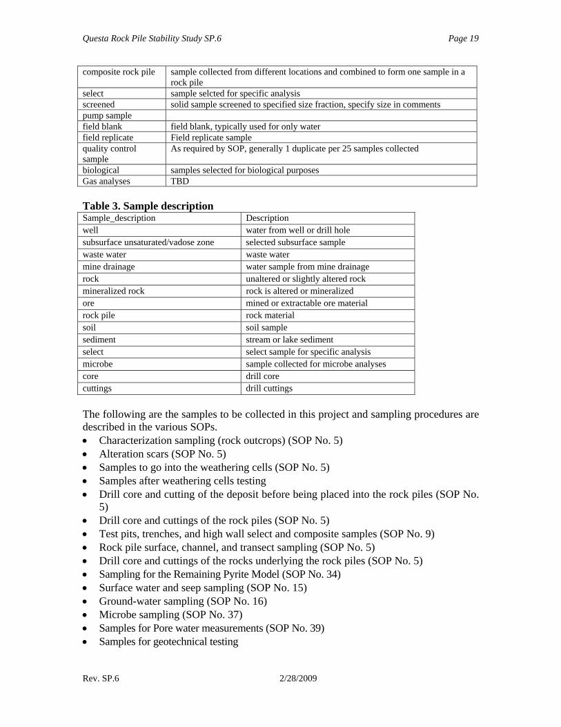
composite rock pile sample collected from different locations and combined to form one sample in a rock pile
select sample selcted for specific analysis screened solid sample screened to specified size fraction, specify size in comments pump sample field blank field blank, typically used for only water field replicate Field replicate sample quality control sample
As required by SOP, generally 1 duplicate per 25 samples collected
biological samples selected for biological purposes Gas analyses TBD Table 3. Sample description Sample_description Description well water from well or drill hole subsurface unsaturated/vadose zone selected subsurface sample waste water waste water mine drainage water sample from mine drainage rock unaltered or slightly altered rock mineralized rock rock is altered or mineralized ore mined or extractable ore material rock pile rock material soil soil sample sediment stream or lake sediment select select sample for specific analysis microbe sample collected for microbe analyses core drill core cuttings drill cuttings The following are the samples to be collected in this project and sampling procedures are described in the various SOPs. • Characterization sampling (rock outcrops) (SOP No. 5) • Alteration scars (SOP No. 5) • Samples to go into the weathering cells (SOP No. 5) • Samples after weathering cells testing • Drill core and cutting of the deposit before being placed into the rock piles (SOP No.
5) • Drill core and cuttings of the rock piles (SOP No. 5) • Test pits, trenches, and high wall select and composite samples (SOP No. 9) • Rock pile surface, channel, and transect sampling (SOP No. 5) • Drill core and cuttings of the rocks underlying the rock piles (SOP No. 5) • Sampling for the Remaining Pyrite Model (SOP No. 34) • Surface water and seep sampling (SOP No. 15) • Ground-water sampling (SOP No. 16) • Microbe sampling (SOP No. 37) • Samples for Pore water measurements (SOP No. 39) • Samples for geotechnical testing
Questa Rock Pile Stability Study SP.6 Page 20
Rev. SP.6 2/28/2009
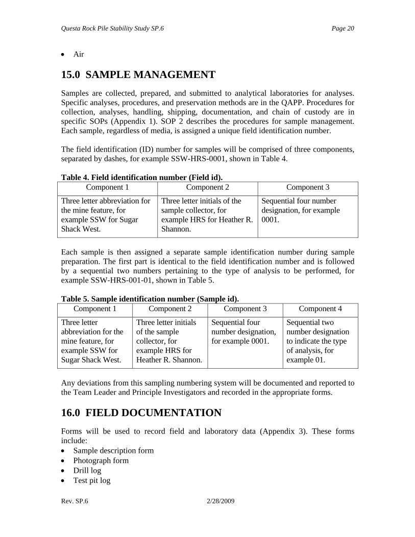
• Air 15.0 SAMPLE MANAGEMENT Samples are collected, prepared, and submitted to analytical laboratories for analyses. Specific analyses, procedures, and preservation methods are in the QAPP. Procedures for collection, analyses, handling, shipping, documentation, and chain of custody are in specific SOPs (Appendix 1). SOP 2 describes the procedures for sample management. Each sample, regardless of media, is assigned a unique field identification number. The field identification (ID) number for samples will be comprised of three components, separated by dashes, for example SSW-HRS-0001, shown in Table 4. Table 4. Field identification number (Field id).
Component 1 Component 2 Component 3
Three letter abbreviation for the mine feature, for example SSW for Sugar Shack West.
Three letter initials of the sample collector, for example HRS for Heather R. Shannon.
Sequential four number designation, for example 0001.
Each sample is then assigned a separate sample identification number during sample preparation. The first part is identical to the field identification number and is followed by a sequential two numbers pertaining to the type of analysis to be performed, for example SSW-HRS-001-01, shown in Table 5. Table 5. Sample identification number (Sample id).
Component 1 Component 2 Component 3 Component 4
Three letter abbreviation for the mine feature, for example SSW for Sugar Shack West.
Three letter initials of the sample collector, for example HRS for Heather R. Shannon.
Sequential four number designation, for example 0001.
Sequential two number designation to indicate the type of analysis, for example 01.
Any deviations from this sampling numbering system will be documented and reported to the Team Leader and Principle Investigators and recorded in the appropriate forms. 16.0 FIELD DOCUMENTATION Forms will be used to record field and laboratory data (Appendix 3). These forms include: • Sample description form • Photograph form • Drill log • Test pit log
Questa Rock Pile Stability Study SP.6 Page 21
Rev. SP.6 2/28/2009
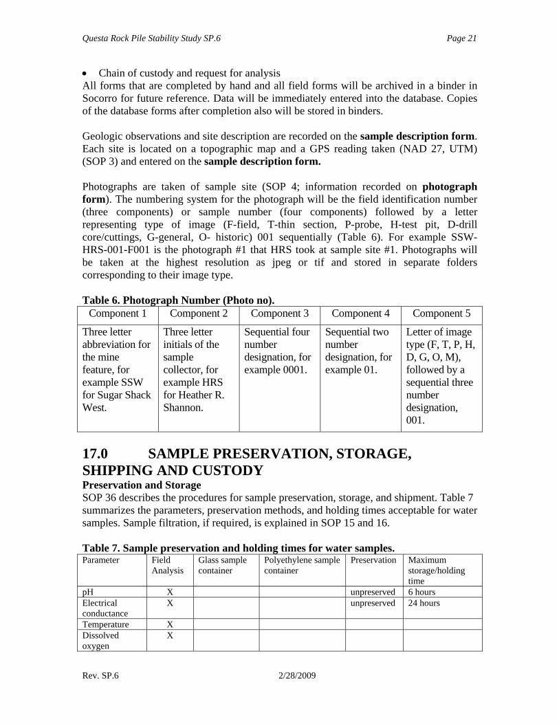
• Chain of custody and request for analysis All forms that are completed by hand and all field forms will be archived in a binder in Socorro for future reference. Data will be immediately entered into the database. Copies of the database forms after completion also will be stored in binders. Geologic observations and site description are recorded on the sample description form. Each site is located on a topographic map and a GPS reading taken (NAD 27, UTM) (SOP 3) and entered on the sample description form. Photographs are taken of sample site (SOP 4; information recorded on photograph form). The numbering system for the photograph will be the field identification number (three components) or sample number (four components) followed by a letter representing type of image (F-field, T-thin section, P-probe, H-test pit, D-drill core/cuttings, G-general, O- historic) 001 sequentially (Table 6). For example SSW-HRS-001-F001 is the photograph #1 that HRS took at sample site #1. Photographs will be taken at the highest resolution as jpeg or tif and stored in separate folders corresponding to their image type. Table 6. Photograph Number (Photo no).
Component 1 Component 2 Component 3 Component 4 Component 5
Three letter abbreviation for the mine feature, for example SSW for Sugar Shack West.
Three letter initials of the sample collector, for example HRS for Heather R. Shannon.
Sequential four number designation, for example 0001.
Sequential two number designation, for example 01.
Letter of image type (F, T, P, H, D, G, O, M), followed by a sequential three number designation, 001.
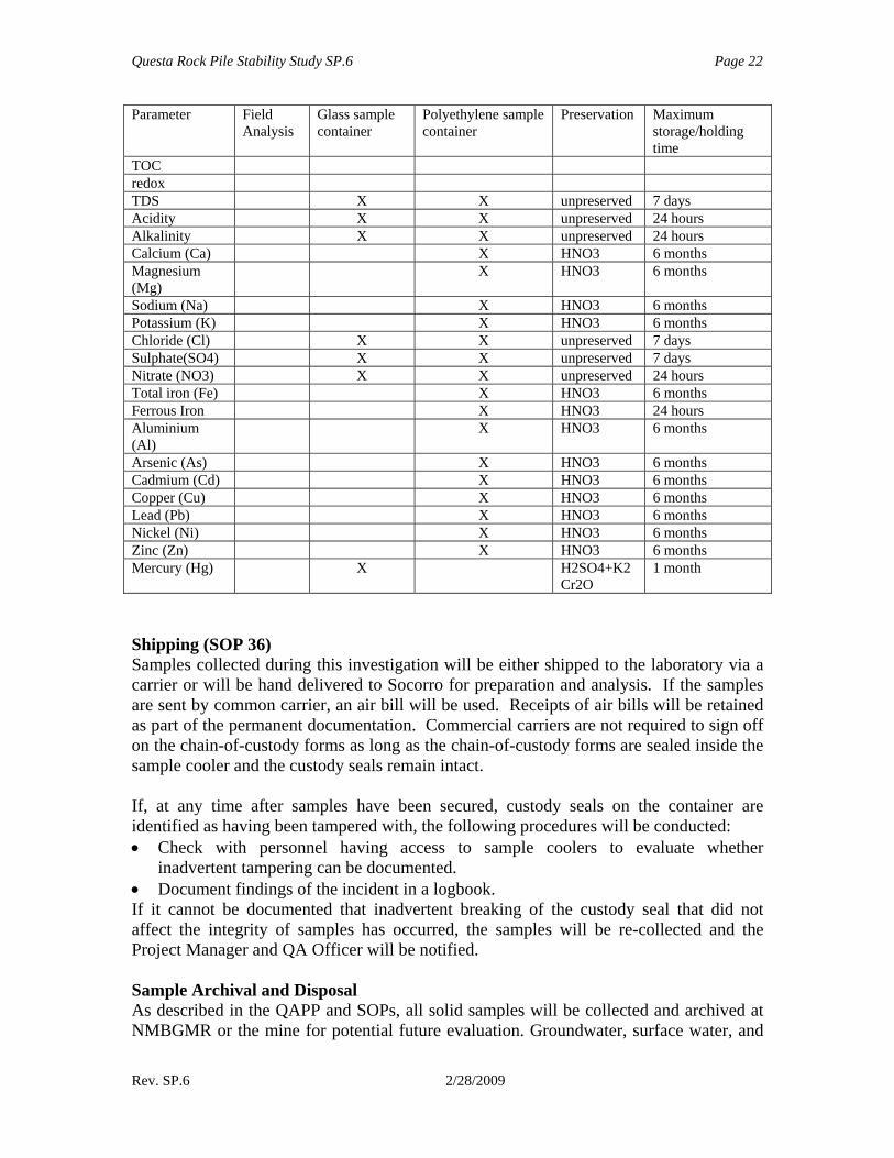
17.0 SAMPLE PRESERVATION, STORAGE, SHIPPING AND CUSTODY Preservation and Storage SOP 36 describes the procedures for sample preservation, storage, and shipment. Table 7 summarizes the parameters, preservation methods, and holding times acceptable for water samples. Sample filtration, if required, is explained in SOP 15 and 16. Table 7. Sample preservation and holding times for water samples. Parameter Field
Analysis Glass sample container
Polyethylene sample container
Preservation Maximum storage/holding time
pH X unpreserved 6 hours Electrical conductance
X unpreserved 24 hours
Temperature X Dissolved oxygen
X
Questa Rock Pile Stability Study SP.6 Page 22
Rev. SP.6 2/28/2009
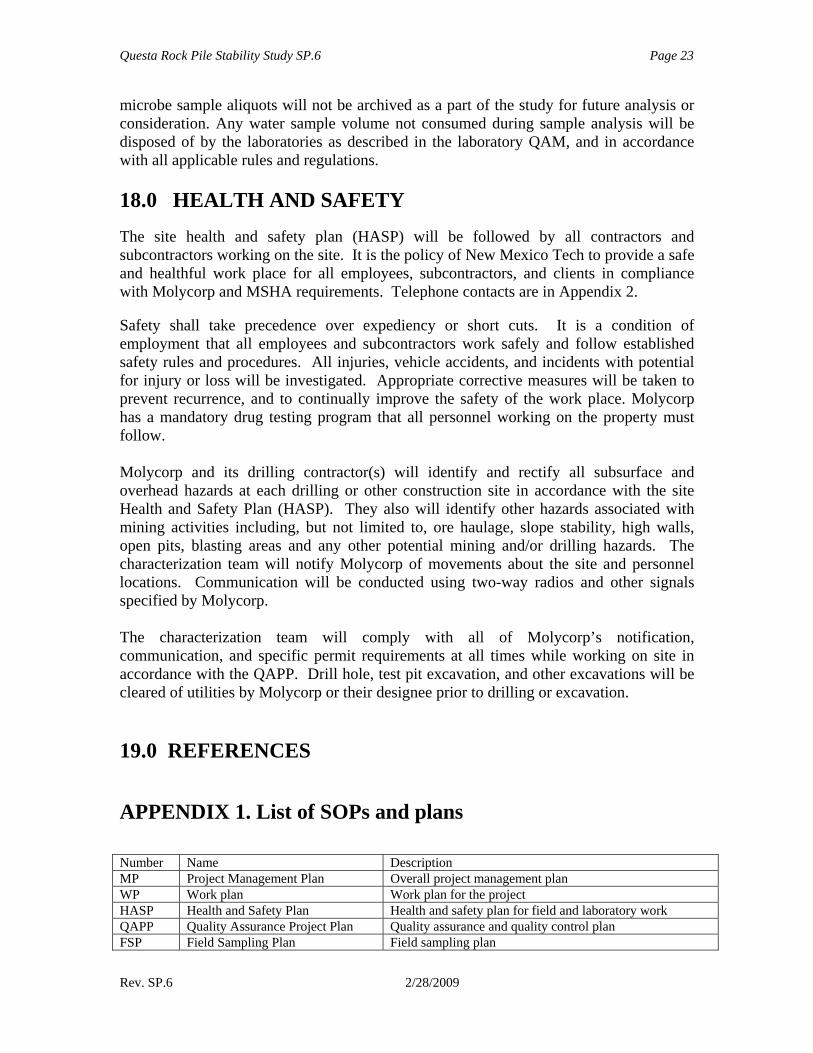
Parameter Field Analysis
Glass sample container
Polyethylene sample container
Preservation Maximum storage/holding time
TOC redox TDS X X unpreserved 7 days Acidity X X unpreserved 24 hours Alkalinity X X unpreserved 24 hours Calcium (Ca) X HNO3 6 months Magnesium (Mg)
X HNO3 6 months
Sodium (Na) X HNO3 6 months Potassium (K) X HNO3 6 months Chloride (Cl) X X unpreserved 7 days Sulphate(SO4) X X unpreserved 7 days Nitrate (NO3) X X unpreserved 24 hours Total iron (Fe) X HNO3 6 months Ferrous Iron X HNO3 24 hours Aluminium (Al)
X HNO3 6 months
Arsenic (As) X HNO3 6 months Cadmium (Cd) X HNO3 6 months Copper (Cu) X HNO3 6 months Lead (Pb) X HNO3 6 months Nickel (Ni) X HNO3 6 months Zinc (Zn) X HNO3 6 months Mercury (Hg) X H2SO4+K2
Cr2O 1 month
Shipping (SOP 36) Samples collected during this investigation will be either shipped to the laboratory via a carrier or will be hand delivered to Socorro for preparation and analysis. If the samples are sent by common carrier, an air bill will be used. Receipts of air bills will be retained as part of the permanent documentation. Commercial carriers are not required to sign off on the chain-of-custody forms as long as the chain-of-custody forms are sealed inside the sample cooler and the custody seals remain intact. If, at any time after samples have been secured, custody seals on the container are identified as having been tampered with, the following procedures will be conducted: • Check with personnel having access to sample coolers to evaluate whether
inadvertent tampering can be documented. • Document findings of the incident in a logbook. If it cannot be documented that inadvertent breaking of the custody seal that did not affect the integrity of samples has occurred, the samples will be re-collected and the Project Manager and QA Officer will be notified. Sample Archival and Disposal As described in the QAPP and SOPs, all solid samples will be collected and archived at NMBGMR or the mine for potential future evaluation. Groundwater, surface water, and
Questa Rock Pile Stability Study SP.6 Page 23
Rev. SP.6 2/28/2009
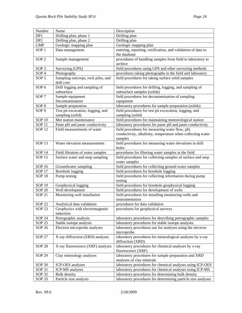
microbe sample aliquots will not be archived as a part of the study for future analysis or consideration. Any water sample volume not consumed during sample analysis will be disposed of by the laboratories as described in the laboratory QAM, and in accordance with all applicable rules and regulations. 18.0 HEALTH AND SAFETY The site health and safety plan (HASP) will be followed by all contractors and subcontractors working on the site. It is the policy of New Mexico Tech to provide a safe and healthful work place for all employees, subcontractors, and clients in compliance with Molycorp and MSHA requirements. Telephone contacts are in Appendix 2. Safety shall take precedence over expediency or short cuts. It is a condition of employment that all employees and subcontractors work safely and follow established safety rules and procedures. All injuries, vehicle accidents, and incidents with potential for injury or loss will be investigated. Appropriate corrective measures will be taken to prevent recurrence, and to continually improve the safety of the work place. Molycorp has a mandatory drug testing program that all personnel working on the property must follow. Molycorp and its drilling contractor(s) will identify and rectify all subsurface and overhead hazards at each drilling or other construction site in accordance with the site Health and Safety Plan (HASP). They also will identify other hazards associated with mining activities including, but not limited to, ore haulage, slope stability, high walls, open pits, blasting areas and any other potential mining and/or drilling hazards. The characterization team will notify Molycorp of movements about the site and personnel locations. Communication will be conducted using two-way radios and other signals specified by Molycorp. The characterization team will comply with all of Molycorp’s notification, communication, and specific permit requirements at all times while working on site in accordance with the QAPP. Drill hole, test pit excavation, and other excavations will be cleared of utilities by Molycorp or their designee prior to drilling or excavation. 19.0 REFERENCES APPENDIX 1. List of SOPs and plans Number Name Description MP Project Management Plan Overall project management plan WP Work plan Work plan for the project HASP Health and Safety Plan Health and safety plan for field and laboratory work QAPP Quality Assurance Project Plan Quality assurance and quality control plan FSP Field Sampling Plan Field sampling plan
Questa Rock Pile Stability Study SP.6 Page 24
Rev. SP.6 2/28/2009
Number Name Description DP1 Drilling plan, phase 1 Drilling plan DP2 Drilling plan, phase 2 Drilling plan GMP Geologic mapping plan Geologic mapping plan SOP 1 Data management entering, reporting, verification, and validation of data to
the database SOP 2 Sample management procedures of handling samples from field to laboratory to
archive SOP 3 Surveying (GPS) field procedures using GPS and other surveying methods SOP 4 Photography procedures taking photographs in the field and laboratory SOP 5 Sampling outcrops, rock piles, and
drill core field procedures for taking surface solid samples
SOP 6 Drill logging and sampling of subsurface
field procedures for drilling, logging, and sampling of subsurface samples (solids)
SOP 7 Sample equipment Decontamination
field procedures for decontamination of sampling equipment
SOP 8 Sample preparation laboratory procedures for sample preparation (solids) SOP 9 Test pit excavation, logging, and
sampling (solid) field procedures for test pit excavation, logging, and sampling (solid)
SOP 10 Met station maintenance field procedures for maintaining meteorological station SOP 11 Paste pH and paste conductivity laboratory procedures for paste pH and paste conductivity SOP 12 Field measurements of water field procedures for measuring water flow, pH,
conductivity, alkalinity, temperature when collecting water samples
SOP 13 Water elevation measurements field procedures for measuring water elevations in drill holes
SOP 14 Field filtration of water samples procedures for filtering water samples in the field SOP 15 Surface water and seep sampling field procedures for collecting samples of surface and seep
water samples SOP 16 Groundwater sampling field procedures for collecting ground-water samples SOP 17 Borehole logging field procedures for borehole logging SOP 18 Pump testing field procedures for collecting information during pump
testing SOP 19 Geophysical logging field procedures for borehole geophysical logging SOP 20 Well development field procedures for development of wells SOP 21 Monitoring well installation field procedures for installing monitoring wells and
instrumentation SOP 22 Analytical data validation procedures for data validation SOP 23 Geophysics with electromagnetic
induction procedures for geophysical surveys
SOP 24 Petrographic analysis laboratory procedures for describing petrographic samples SOP 25 Stable isotope analysis laboratory procedures for stable isotope analyses SOP 26 Electron microprobe analyses laboratory procedures use for analyses using the electron
microprobe SOP 27 X-ray diffraction (XRD) analyses laboratory procedures for mineralogical analyses by x-ray
diffraction (XRD) SOP 28 X-ray fluorescence (XRF) analyses laboratory procedures for chemical analyses by x-ray
fluorescence (XRF) SOP 29 Clay mineralogy analyses laboratory procedures for sample preparation and XRD
analyses of clay minerals SOP 30 ICP-OES analyses laboratory procedures for chemical analyses using ICP-OES SOP 31 ICP-MS analyses laboratory procedures for chemical analyses using ICP-MS SOP 32 Bulk density laboratory procedures for determining bulk density SOP 33 Particle size analysis laboratory procedures for determining particle size analyses
Questa Rock Pile Stability Study SP.6 Page 25
Rev. SP.6 2/28/2009
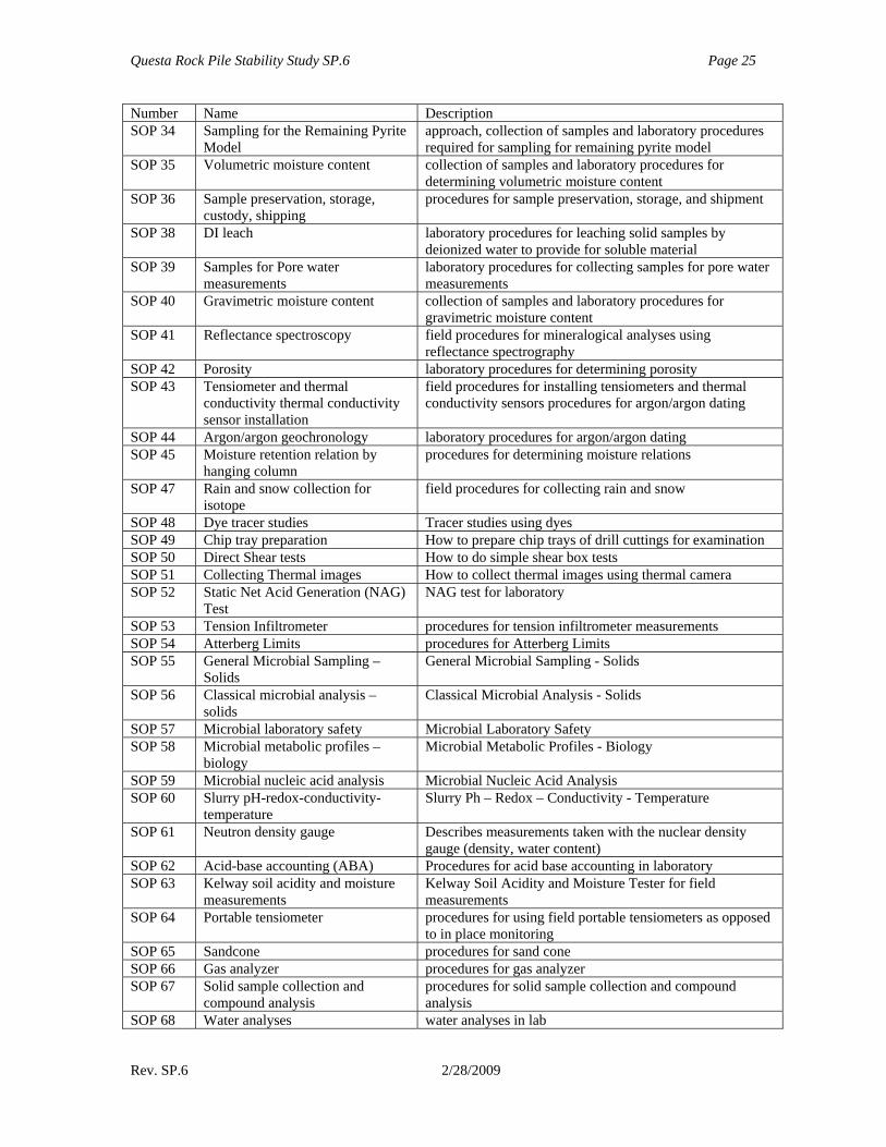
Number Name Description SOP 34 Sampling for the Remaining Pyrite
Model approach, collection of samples and laboratory procedures required for sampling for remaining pyrite model
SOP 35 Volumetric moisture content collection of samples and laboratory procedures for determining volumetric moisture content
SOP 36 Sample preservation, storage, custody, shipping
procedures for sample preservation, storage, and shipment
SOP 38 DI leach laboratory procedures for leaching solid samples by deionized water to provide for soluble material
SOP 39 Samples for Pore water measurements
laboratory procedures for collecting samples for pore water measurements
SOP 40 Gravimetric moisture content collection of samples and laboratory procedures for gravimetric moisture content
SOP 41 Reflectance spectroscopy field procedures for mineralogical analyses using reflectance spectrography
SOP 42 Porosity laboratory procedures for determining porosity SOP 43 Tensiometer and thermal
conductivity thermal conductivity sensor installation
field procedures for installing tensiometers and thermal conductivity sensors procedures for argon/argon dating
SOP 44 Argon/argon geochronology laboratory procedures for argon/argon dating SOP 45 Moisture retention relation by
hanging column procedures for determining moisture relations
SOP 47 Rain and snow collection for isotope
field procedures for collecting rain and snow
SOP 48 Dye tracer studies Tracer studies using dyes SOP 49 Chip tray preparation How to prepare chip trays of drill cuttings for examination SOP 50 Direct Shear tests How to do simple shear box tests SOP 51 Collecting Thermal images How to collect thermal images using thermal camera SOP 52 Static Net Acid Generation (NAG)
Test NAG test for laboratory
SOP 53 Tension Infiltrometer procedures for tension infiltrometer measurements SOP 54 Atterberg Limits procedures for Atterberg Limits SOP 55 General Microbial Sampling –
Solids General Microbial Sampling - Solids
SOP 56 Classical microbial analysis – solids
Classical Microbial Analysis - Solids
SOP 57 Microbial laboratory safety Microbial Laboratory Safety SOP 58 Microbial metabolic profiles –
biology Microbial Metabolic Profiles - Biology
SOP 59 Microbial nucleic acid analysis Microbial Nucleic Acid Analysis SOP 60 Slurry pH-redox-conductivity-
temperature Slurry Ph – Redox – Conductivity - Temperature
SOP 61 Neutron density gauge Describes measurements taken with the nuclear density gauge (density, water content)
SOP 62 Acid-base accounting (ABA) Procedures for acid base accounting in laboratory SOP 63 Kelway soil acidity and moisture
measurements Kelway Soil Acidity and Moisture Tester for field measurements
SOP 64 Portable tensiometer procedures for using field portable tensiometers as opposed to in place monitoring
SOP 65 Sandcone procedures for sand cone SOP 66 Gas analyzer procedures for gas analyzer SOP 67 Solid sample collection and
compound analysis procedures for solid sample collection and compound analysis
SOP 68 Water analyses water analyses in lab
Questa Rock Pile Stability Study SP.6 Page 26
Rev. SP.6 2/28/2009
Number Name Description SOP 69 Other chemical analyses on solids other chemical analyses on solids (ammonia, nitrate,
fluorine, etc) SOP 70 Sand replacement calculates volumetric moisture content and bulk density SOP 71 Guelph permeameter procedures for guelph permeameter measurements SOP 72 SWCC Soil water characteristic curve (UBC) SOP 73 Falling head Permeability Permeability by falling head method SOP 75 Specific gravity procedures for determining specific gravity SOP 76 Slake durability procedures for slake durability tests SOP 77 Point load procedures for point load tests SOP 78 Humidity cell testing procedures for weathering cells tests SOP 79 Sample preparation for humidity
cell testing procedures for weathering cells sample selection and preparation
SOP 90 XRD sample preparation for pyrite reserve model
XRD sample preparation for pyrite reserve model
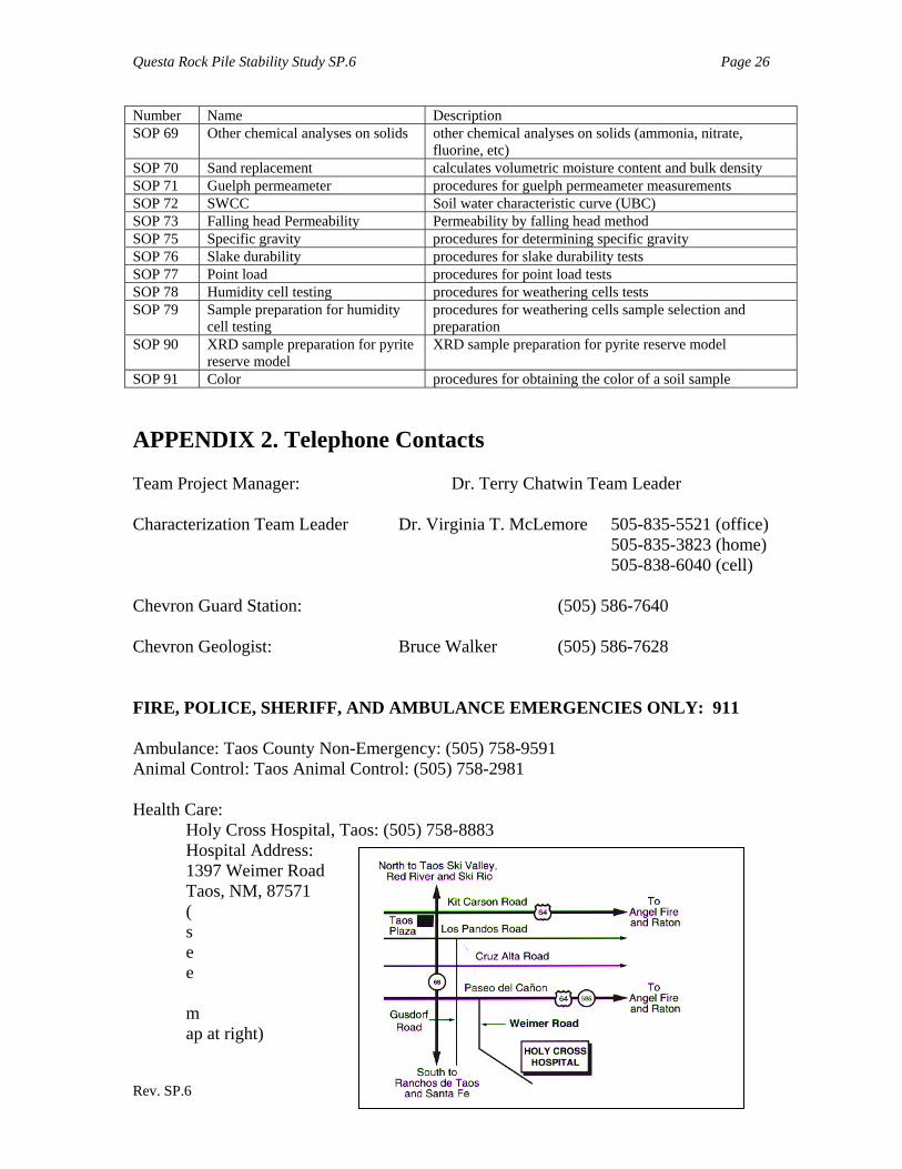
SOP 91 Color procedures for obtaining the color of a soil sample APPENDIX 2. Telephone Contacts Team Project Manager: Dr. Terry Chatwin Team Leader Characterization Team Leader Dr. Virginia T. McLemore 505-835-5521 (office) 505-835-3823 (home) 505-838-6040 (cell) Chevron Guard Station: (505) 586-7640 Chevron Geologist: Bruce Walker (505) 586-7628 FIRE, POLICE, SHERIFF, AND AMBULANCE EMERGENCIES ONLY: 911 Ambulance: Taos County Non-Emergency: (505) 758-9591 Animal Control: Taos Animal Control: (505) 758-2981 Health Care:
Holy Cross Hospital, Taos: (505) 758-8883 Hospital Address: 1397 Weimer Road Taos, NM, 87571 (see map at right)
Questa Rock Pile Stability Study SP.6 Page 27
Rev. SP.6 2/28/2009
Questa Health Center: (505) 586-0315 Red River Medical Office: (505) 754-2379
Poison And Drug Information Center: 1-800-432-6866
Police - Non Emergency:
Questa: (505) 586-1196 Red River: (505) 754-6166 Taos: (505) 758-4656 Sheriff - Non Emergency: (505) 758-4709 State Police - Non Emergency: (505) 758-8878 Note: Cellular telephones often do not work at the field site. If necessary, use telephones located at the Red River Waste Water Treatment Plant, the Town of Red River, or the Molycorp mine offices.