Embed Size (px)
Citation preview

SAMPLING AND ANALYSIS PLAN
Section 10.0
Radiological Survey
OCTOBER 2009
Submitted To:
New Mexico Mining and Minerals Division &
U.S. Forest Service (Cibola National Forest)
Prepared by:
Roca Honda Resources, LLC 4001 Office Court, Suite 102, Santa Fe, NM 87507
Sampling and Analysis Plan Contents Roca Honda Mine – Revision No. 2 October 2009 Page ii
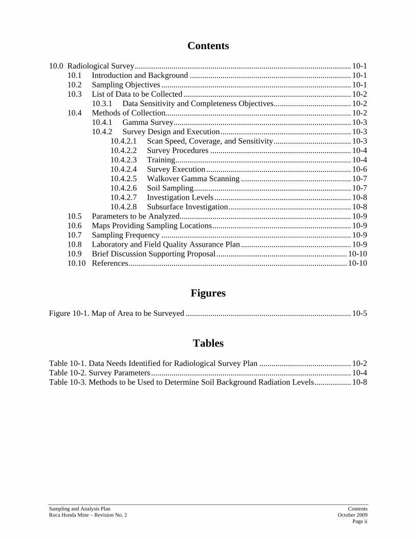
Contents 10.0 Radiological Survey .......................................................................................................... 10-1
10.1 Introduction and Background ............................................................................... 10-1 10.2 Sampling Objectives ............................................................................................. 10-1 10.3 List of Data to be Collected .................................................................................. 10-2
10.3.1 Data Sensitivity and Completeness Objectives ...................................... 10-2 10.4 Methods of Collection........................................................................................... 10-2
10.4.1 Gamma Survey....................................................................................... 10-3 10.4.2 Survey Design and Execution ................................................................ 10-3
10.4.2.1 Scan Speed, Coverage, and Sensitivity ...................................... 10-3 10.4.2.2 Survey Procedures ..................................................................... 10-4 10.4.2.3 Training ...................................................................................... 10-4 10.4.2.4 Survey Execution ....................................................................... 10-6 10.4.2.5 Walkover Gamma Scanning ...................................................... 10-7 10.4.2.6 Soil Sampling ............................................................................. 10-7 10.4.2.7 Investigation Levels ................................................................... 10-8 10.4.2.8 Subsurface Investigation ............................................................ 10-8
10.5 Parameters to be Analyzed .................................................................................... 10-9 10.6 Maps Providing Sampling Locations .................................................................... 10-9 10.7 Sampling Frequency ............................................................................................. 10-9 10.8 Laboratory and Field Quality Assurance Plan ...................................................... 10-9 10.9 Brief Discussion Supporting Proposal ................................................................ 10-10 10.10 References ........................................................................................................... 10-10
Figures
Figure 10-1. Map of Area to be Surveyed ................................................................................. 10-5
Tables Table 10-1. Data Needs Identified for Radiological Survey Plan ............................................. 10-2 Table 10-2. Survey Parameters .................................................................................................. 10-4 Table 10-3. Methods to be Used to Determine Soil Background Radiation Levels .................. 10-8

Sampling and Analysis Plan Section 10.0—Radiological Survey Roca Honda Mine – Revision No. 2 October 2009 Page 10-1
10.0 Radiological Survey
10.1 Introduction and Background
Guidelines for residual radioactivity are expressed in terms of radiation or activity levels above ambient background for a specific site of interest. It is therefore necessary to establish background levels in order to be able to assess possible impacts resulting from mining operations.
Background, as related to radiological survey operations, is of two general categories. One category is the concentration of radioactive material naturally occurring in environmental media (air, soil, water, vegetation) and incorporated in construction materials. Examples of such radionuclides are carbon-14, potassium-40, uranium and thorium and their associated daughter products, and cesium-137 from worldwide fallout. The second category of background radiation is the direct radiation level produced by the materials from the first category, plus the direct radiation from cosmic radiation.
Concentrations of naturally-occurring radioactive materials vary, as do direct radiation levels from those materials and cosmic sources. Background radiation will therefore be a distribution of values, rather than a single value. The range may vary from location to location on a particular site; the degree of variation may be small or significant enough that more than one background value must be determined for application at the site.
The radionuclides of interest for this survey are those associated with natural uranium and its decay products, particularly radium, radon, and natural thorium and its decay products. Uranium is naturally found in soils at levels ranging from 0.2 pCi/g to as high as 8 pCi/g (Effects of Radiation United Nations Scientific Committee on the Effects of Atomic Radiation, 1993, Report to the General Assembly, New York). Generally speaking, in New Mexico, the background level of uranium in soils is expected to be around 1 pCi/g. However, if natural outcrops, surface deposits, or drill cuttings from historical exploration activities are encountered, surface soils may contain uranium concentrations ranging from a few hundred pCi/g to several thousand pCi/g and would be easily distinguishable as elevated background levels. The New Mexico soils will contain low levels of thorium as well.
10.2 Sampling Objectives
The survey objective is to perform a radiological baseline assessment of the gamma radiation and existing concentration of naturally occurring radionuclides in soils associated with the Roca Honda permit area. The assessment will determine baseline gamma radiation levels and radionuclide concentrations and establish ranges of natural background conditions. The survey will take place within all accessible areas of Sections 9, 10, and 16.
No mining has previously occurred on the property; however, more than 400 exploratory holes were drilled in the late 1970’s and early 1980’s. As discussed in Section 3.0, some drill cuttings may have been left behind on the surface and may have contained nominal uranium ore residues (see Figure 3-1). Baseline conditions will be established near the holes as well as for other areas around the permit area. Steep slopes will not be surveyed because of safety considerations. Section 6.0 of this SAP, Topsoil, discusses topsoil characterization for the Roca Honda permit area and the associated soil sampling.
Sampling and Analysis Plan Section 10.0—Radiological Survey Roca Honda Mine – Revision No. 2 October 2009 Page 10-2
10.3 List of Data to be Collected
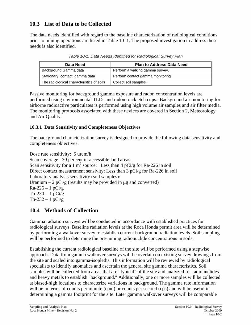
The data needs identified with regard to the baseline characterization of radiological conditions prior to mining operations are listed in Table 10–1. The proposed investigation to address these needs is also identified.
Table 10-1. Data Needs Identified for Radiological Survey Plan
Data Need Plan to Address Data Need Background Gamma data Perform a walking gamma survey. Stationary, contact, gamma data Perform contact gamma monitoring The radiological characteristics of soils Collect soil samples.
Passive monitoring for background gamma exposure and radon concentration levels are performed using environmental TLDs and radon track etch cups. Background air monitoring for airborne radioactive particulates is performed using high volume air samples and air filter media. The monitoring protocols associated with these devices are covered in Section 2, Meteorology and Air Quality.
10.3.1 Data Sensitivity and Completeness Objectives
The background characterization survey is designed to provide the following data sensitivity and completeness objectives.
Dose rate sensitivity: 5 urem/h Scan coverage: 30 percent of accessible land areas. Scan sensitivity for a 1 m2 source: Less than 4 pCi/g for Ra-226 in soil Direct contact measurement sensivity: Less than 3 pCi/g for Ra-226 in soil Laboratory analysis sensitivity (soil samples): Uranium – 2 pCi/g (results may be provided in μg and converted) Ra-226 – 1 pCi/g Th-230 - 1 pCi/g Th-232 – 1 pCi/g
10.4 Methods of Collection
Gamma radiation surveys will be conducted in accordance with established practices for radiological surveys. Baseline radiation levels at the Roca Honda permit area will be determined by performing a walkover survey to establish current background radiation levels. Soil sampling will be performed to determine the pre-mining radionuclide concentrations in soils.
Establishing the current radiological baseline of the site will be performed using a stepwise approach. Data from gamma walkover surveys will be overlain on existing survey drawings from the site and scaled into gamma-isopleths. This information will be reviewed by radiological specialists to identify anomalies and ascertain the general site gamma characteristics. Soil samples will be collected from areas that are “typical” of the site and analyzed for radionuclides and heavy metals to establish "background." Additionally, one or more samples will be collected at biased-high locations to characterize variations in background. The gamma rate information will be in terms of counts per minute (cpm) or counts per second (cps) and will be useful in determining a gamma footprint for the site. Later gamma walkover surveys will be comparable

Sampling and Analysis Plan Section 10.0—Radiological Survey Roca Honda Mine – Revision No. 2 October 2009 Page 10-3
to this same footprint, but may not match the baseline results exactly in terms of cpm or cps. This discrepancy is the result of instrument response variation due to calibration setup along with the impact that environmental temperature and moisture conditions can have on gross count results. However, the objective of determining significant disturbance of the gamma footprint of an area will be achieved.
10.4.1 Gamma Survey
The walkover gamma survey will be performed using GPS-enabled sodium iodide (NaI) instrumentation. The GPS unit is a Trimble receiver and data logger. Data from the radiation detection instrument will be fed, on a real-time basis, to the Trimble data logger as a 2-second integrated count, normalized to cpm. The cpm data is directly correlated to the X, Y, Z, and time data parameters provided by the Trimble unit. These parameters will be stored and later downloaded for processing into visual interpretations using a computer drawing software packages such as Surfer™ or Asset Surveyor™ software.
The Trimble unit will be connected to a Ludlum 2221 with a Ludlum 44-10 detector (or an approved equivalent). This detector has a Minimum Detectable Activity of less than 3 pCi/g for Ra-226 over a source term of 0.5-meter square or larger when the user is monitoring the audible response (see NUREG 1507, Table 6.4). Additionally, this information will be collected and stored as ~2.2-second integrated counts in the Trimble data logger; each count represents about 1-meter square of information. The Ludlum 2221 is a rate meter scaler instrument compatible with multiple detectors with user adjustments for voltage and threshold settings. It can also be used in a window in/out mode. The instrument provides a “gross count” in the window out mode, providing a “count” for all radiation detected above the threshold in the specified count time. The Ludlum 44-10 detector is a 2 × 2-inch NaI detector with incorporated photomultiplier tube.
The Ludlum 44-10 will be calibrated to a Cs-137 source by an approved vendor. The calibration certificates for all instrumentation will be maintained for inclusion in the final report. Cs-137 is a mid-range gamma source (0.661 megaelectron volt [MeV]) that is commonly selected to be reasonably representative of the mid-range and higher range gamma energies expected to be encountered at the Roca Honda permit area. Daily performance checks will be performed using a Cs-137, 1-microcurie button source.
10.4.2 Survey Design and Execution
The survey plan is based upon the guidance provided in NUREG-1575 and NUREG/CR-5849, with modifications for the anticipated site conditions and in deference to the overall survey objectives.
10.4.2.1 Scan Speed, Coverage, and Sensitivity
Scan speed, coverage, and sensitivity are provided in Table 10–2. The Roca Honda permit area will be surveyed by walking transect lines 3 meters apart (as terrain and vegetation permit). This distance will provide thorough coverage of the area to be disturbed. A map showing the area to be surveyed is shown in Figure 10–1. The immediate edge of the road and the borrow ditch along Highway 605 and any haul roads will be scanned and 6-second direct counts will be collected every 200 – 300 feet. In addition, the ore haulage roads in an out of the permit area as well as a length of the public highway serving the permit area will be surveyed. The length of public road to be surveyed will be determined at a later date.

Sampling and Analysis Plan Section 10.0—Radiological Survey Roca Honda Mine – Revision No. 2 October 2009 Page 10-4
Table 10-2. Survey Parameters
Area *Scan Spacing Speed **Coverage (%) ***Estimated Sensitivity Roads 2 paths 0.5 m/s 100 2–3 pCi/g
Areas to be Disturbed 3 meters 0.5 m/s 30 2–3 pCi/g * Scan path spacing on the road is dependent upon the width of the road – the survey objective is to cover no less than 50 % of the road (biased towards tracks or other collection points); 2 paths would cover approximately 4 m. If the road is consistently wider than this, add one or more paths. ** Coverage is general calculated as follows (a “path” is the width between walking paths chosen during the walkover gamma scanning): 1-meter scan path = 100% coverage 2-meter scan path = 50% coverage 3-meter scan path = 30% coverage 5-meter scan path = 20 % coverage 10-meter scan path = 10% coverage *** Sensitivity is based upon guidance provided by NUREG-1507 and assumes a 2 x 2-inch NaI detector with a background of 10,000 cpm, an observation interval of 1 second, and a level of performance, d’, of 1.38. Given on-site conditions, sensitivity may be estimated more accurately when the walkover gamma scan results are compared to samples taken at the Roca Honda permit area.
This layout may be modified in the field due to dense vegetation, steep terrain, fencing, or other constraints. The survey speed or rate of scanning is designed to detect areas of elevated radiation of at least 1 square meter.
10.4.2.2 Survey Procedures
Standard operating procedures, plans, and manuals developed by RHR will be used to complete the survey. These survey procedures, copies of which are located in RHR’s document files, include:
• HS-100.100, Health and Safety Plan for Radiological Survey Activities.
• QA-100.100, Quality Assurance for Radiological Survey Activities.
• RP-105.500, Radiological Survey Activities, Procedure 2.2, Surface Scanning.
• RP-105, Instrumentation and Measurement: General.
• RP-105.100, Instrumentation: Calibration.
• RP-105.323, Field Operation of the Trimble TSC1 Data Collector.
• RP-105.219, QC Check of the Trimble Pro XRS Sub-meter GPS.
• GPS Data Processing Handbook.
• RP-105.200, Instrumentation: Setup and Performance Checks.
• RP-105.308, Operation of the Ludlum Model 44-10 Gamma Scintillation Detector.
10.4.2.3 Training
Each member of the survey team will be experienced in his or her particular area of expertise as verified by a current work resume. Additionally, each field member will have read this plan. A training session on this plan will be conducted by the Field Team Leader, a senior health physicist or delegated individual. Each field team member will read the applicable portions of the plans, procedures, and manuals listed above.

Sampling and Analysis Plan Section 10.0—Radiological Survey Roca Honda Mine – Revision No. 2 October 2009 Page 10-5
Figure 10-1. Map of Area to be Surveyed

Sampling and Analysis Plan Section 10.0—Radiological Survey Roca Honda Mine – Revision No. 2 October 2009 Page 10-6
10.4.2.4 Survey Execution
Sequence of Activities
The crew will be mobilized to the area and get familiar with the Roca Honda permit area, set up and test their equipment, and finalize their daily approach plans. The general sequence will be as follows:
[1] Unpack and assemble instrumentation.
[2] Establish communications with local contacts and confirm site access.
[3] Tour site, get the lay of the land, and find a survey marker.
[4] Set up radiological instrumentation check-out paperwork.
[5] Set up GPS check-out paperwork.
[6] Perform daily GPS checks of the following:
• Power • Position Dilution of Precision (P-DOP) check • Known point check • Data acquisition check
[7] Perform daily radiological instrumentation checks of the following:
• Battery • High voltage • Threshold • Background • Source • Site known point check
[8] Perform the following walkover gamma scan activities:
• Follow the topographic drawings showing the areas to be surveyed:
− Locate existing roads running to the proposed mine site areas. Make 2 to 4 passes along identified routes.
− Locate survey areas. It may be appropriate to mark/establish boundaries.
− Scan the areas:
Walk the perimeter. Walk the interior on 3-meter path spacing. If time allows, crisscross the interior on 3-meter path spacing.
• Review initial data set results and field notes.
• Review plan objectives.
• Close any gaps.

Sampling and Analysis Plan Section 10.0—Radiological Survey Roca Honda Mine – Revision No. 2 October 2009 Page 10-7
[9] Perform sampling activities:
• Three samples will be collected of each typical soil found at the site to determine background values.
• One to ten samples will be collected from the area with the highest reading found on site.
• One to three samples may be collected from other areas exhibiting anomalous characteristics (e.g., drill hole cuttings, differing soil type, radiation level).
[10] Package samples for shipping, complete the COC form, and ship samples to lab.
10.4.2.5 Walkover Gamma Scanning
Walkover gamma scanning will be conducted at the frequency and pace specified in the survey parameters and following the guidance contained in RP-105.500, Radiological Survey Activities, Procedure 2.2, “Surface Scanning.” Daily on-site performance checks will be performed at the beginning and midpoint of each day. The instrumentation will be taken to an established location, and a 1-minute reading will be taken and recorded in the survey logbook. The information recorded will include:
• The time and date of the reading.
• Instrumentation used (this can be instrument 1, 2, etc., if these instruments are associated by SN to these numbers with the logbook).
• Names of surveys.
• Counting interval.
• Data units.
• Name of recorder.
10.4.2.6 Soil Sampling
Soil samples will be collected following the guidance contained in RP-105.500, Radiological Survey Activities, Procedure 3.2, “Soil Sampling.” Using a NaI, 2x2 inch, detector, and a 0.1 to 1.0 count time, the survey team will get an “on-contact” and a “1-meter” reading above each sample location prior to sampling. A surface (not downhole) reading will be taken post sample collection as well. A general description of the soil type and the rationale for sample location inclusion in the survey will be noted in the survey log. A tissue equivalent dose rate instrument will be used to take dose rates at these same measurement points.
The sample will be collected from the top 15 centimeters of soil. The soil sampling procedure outlined in Section 3.2.2 of RP-105.500, Radiological Survey Activities, Procedure 2.2, “Surface Scanning” will be followed specifically, except that the samples will be double bagged and secured with duct tape. If a sample container is used, the container holding the soil will be bagged.
Each sample will be identified by writing the sample ID and all pertinent sample information directly on the sample bag or container. The survey crew will start a COC form for the sample. The Field Team Leader will complete the COC and will deliver or ship the samples to the

Sampling and Analysis Plan Section 10.0—Radiological Survey
analytical laboratory. Samples will be analyzed for total uranium, isotopic thorium, and radium. Table 10-3 provides analytical methods and container size for the soil background radiation sampling.
Table 10-3. Methods to be Used to Determine Soil Background Radiation Levels
Analyte Extraction Method
Analysis Method
Sample Amount and Container
Total Uranium SW 3050 SW 6020 1500 g (half of plastic 1 gallon
Ziploc bag)
Isotopic Thorium SW 3050 E 907.0 Radium 226 SW 3050 E 903 Radium 228 SW 3050 RA-05
Sample locations and ID along with contact and 1-meter gamma results will be recorded in the survey logbook for each sample. Samples will be identified and marked as follows (note that, “RH” stands for Roca Honda, and “S” stands for soil):
• RH-S-Sequential Number
• Location ID
• Depth
• Date
• Technician
Example: RH-S-002 N: 158625 E: 2768221 0 – 6 inches 4/22/09 NCK
10.4.2.7 Investigation Levels
The survey crew will monitor the audible response at all times while scanning, notable increases in count rate may be cause for investigation. The survey crew will note general area count rates and ranges. Samples will be collected from average count rate soils and those exhibiting higher count rates. Areas with apparent drill cuttings will be identified and levels recorded.
10.4.2.8 Subsurface Investigation
Soil sampling and analysis will be conducted to determine the radionuclide concentrations in subsequent 6-inch intervals if an area exhibits levels of gamma three times a typically expected level.
If soil conditions and terrain allow, downhole gamma logging will be conducted at 6-inch intervals from 0 to 72 inches or “bottom of hole.” Downhole soil samples will be taken if anomalous conditions exist. At least three downhole soil samples will be collected to allow for the development of a correlation between count rate data and the radionuclide content of subsurface soil.
Roca Honda Mine – Revision No. 2 October 2009 Page 10-8

Sampling and Analysis Plan Section 10.0—Radiological Survey Roca Honda Mine – Revision No. 2 October 2009 Page 10-9
10.5 Parameters to be Analyzed
The gamma rate information will be in terms of cpm or cps and will be useful in determining a gamma footprint for the site.
Soil samples will be analyzed for total uranium, isotopic thorium, and radium. Table 10-3 provides analytical methods and container size for the soil background radiation sampling.
10.6 Maps Providing Sampling Locations
Figure 10-1 provides the area to be surveyed.
10.7 Sampling Frequency
The sampling frequency for the walkover gamma scan activities will be:
• 2 to 4 passes along roads to be used,
• 3-meter path spacing on the interior of the permit area,
• crisscross the interior on 3-meter path spacing.
The sampling frequency for soil sampling will be:
• Three samples of each typical soil found at the site to determine background values.
• One to ten samples from the area with the highest reading found on site.
• One to three samples from other areas exhibiting anomalous characteristics (e.g., drill hole cuttings, differing soil type, radiation level).
10.8 Laboratory and Field Quality Assurance Plan
Gamma radiation surveys will be conducted in accordance with established practices for radiological survey. The survey plan is based upon the guidance provided in NUREG-1575 and NUREG/CR-5849. Standard operating procedures, plans, and manuals developed by the RHR radiological consultants will be used to complete the survey (Section 10.4.2).
The Field Team Leader and each member of the survey team will be experienced in his or her particular area of expertise as verified by a current work resume. Additionally, each field member will have read this plan and the procedures and applicable manuals. A training session on this plan and procedures will be conducted by the Field Team Leader or delegated individual.
The calibration certificates for the instrumentation will be maintained for inclusion in the final report. Most of the instruments are calibrated by the manufacturer and daily performance checks will be performed to ensure proper operation. Any improperly functioning instruments will be returned to manufacturer for a replacement.
• “Caution, survey activities must be performed within the operating parameters (temperature, pressure, humidity) of selected instrumentation.
• Caution, survey results may be affected by temporary changes in surface water conditions.”

Sampling and Analysis Plan Section 10.0—Radiological Survey Roca Honda Mine – Revision No. 2 October 2009 Page 10-10
The Trimble data recorder will be downloaded to a computer daily if possible. The data quantity and quality will be reviewed to insure it is usable and complete. If possible, a file will be emailed and/or stored separately to insure against file loss. This information will be reviewed by radiological specialists to identify anomalies and ascertain the general site gamma characteristics.
Soil samples will be collected in accordance with procedures and the Field Team Leader or designee will complete the COC and deliver or ship the samples to the pre-approved analytical laboratory. Samples will be analyzed for total uranium, isotopic thorium, and radium.
Field data will be collected in a bound logbook. The Field Team Leader will record daily activities, survey location, instrument performance checks, soil sampling identification information, handling and shipping information, and other information important for the data analysis. If possible, a copy of all daily entries will be made and stored separately from the logbook. A copy of the logbook will be left at the RHR office when the survey is completed.
10.9 Brief Discussion Supporting Proposal
The objectives of the proposed radiological survey is to characterize and establish baseline gamma radiation conditions and existing concentrations of naturally occurring radionuclides in soils associated with the Roca Honda permit area in advance of mining.
The data from the radiological surveys will be used to determine baseline gamma radiation levels and radionuclide concentrations and establish ranges of natural background conditions prior to surface disturbance activities.
10.10 References
NUREG/CR-5849. Manual for Conducting Radiological Surveys in Support of License Termination (Draft), U.S. Nuclear Regulatory Commission, Washington, D.C., May 1992.
NUREG-1507. Minimum Detectable Concentrations with Typical Radiation Survey Instruments for Various Contaminates and Field Conditions, U.S. Nuclear Regulatory Commission, Washington, D.C., 1997.
NUREG-1575. Multi-Agency Radiation Survey and Site Investigation Manual, Rev. 1, U.S. Nuclear Regulatory Commission, U.S. Department of Energy, U.S. Department of Defense, and U.S. Environmental Protection Agency, Washington, D.C., December 1997.