Embed Size (px)
Citation preview
SAMPLE QUESTION PAPER – I (2015-16)
ENGINEERING GRAPHICS (046)
Time Allowed: 3 hours Maximum Marks: 70
Note:
a) Attempt all the questions.
b) Use both sides of the drawing sheet, if necessary.
c) All dimensions are in millimetres.
d) Missing and mismatching dimensions, if any, may be suitably assumed.
e) Follow the SP: 46, 2003 revised codes. (with First angle method of projection)
f) In no view of question 1, are hidden edges or lines required.
g) In question 4, hidden edges or lines are to be shown in views without section.
h) Number your answers according to questions.
Q1 Answer the following Multiple Choice Questions. Print the correct choice on your
drawing sheet. (1 X 5= 5)
(i) What is the thread angle in degrees of a Metric thread?
(a) 30°
(b) 45°
(c) 60°
(d) 90°
(ii) A circle drawn in isometric projection appears as?
(a) Circle
(b) Round
(c) Ellipse
(d) Spherical
(iii) Section lines are generally inclined with the base, at an angle of?
(a) 00
(b) 450
(c) 500
(d) 900
(iv) Which machine part is called as “HEADLESS BOLT”?
(a) Nut
(b) Screw

(c) Rivet
(d) Stud
(v) M in dimension „Stud of M20‟, stands for
(a) Metric Thread Profile
(b) Square Thread Profile
(c) Knuckle Thread Profile
(d) B.S.W. Thread Profile
Q2 (a) Construct an isometric scale. 4
(b) Draw the isometric projection of an inverted frustum of triangular pyramid (base
triangular edge = 30mm, top triangular edge = 50mm, height=80mm) with one base
edge perpendicular to V.P. and its axis perpendicular to the H.P. Give all the
dimensions and indicate the direction of viewing. 7
(c) An upright cone (diameter = 50mm and height = 70mm) is placed centrally on the
top rectangular face of a pentagonal prism (base side = 50mm and axis = 80mm).
The pentagonal prism is resting on one of its face edges on H.P. with axis parallel to
V.P. and H.P. both. Draw the isometric projection of this combination of solids.
Give the dimensions and indicate the direction of viewing. 13
Q3 (a) Draw to scale 1:1, the front view and top view of a Square Nut (across corner) with
diameter 30mm. Give standard dimensions. 8
OR
Draw to scale 1:1, the full sectional front view of a Single Riveted Lap Joint for
16mm thick plates. Give standard dimensions.
(b) Sketch free hand the front view, top view and side view of a Feather Key with Gib
head at both ends for a shaft of 50mm diameter. Give standard dimensions. 5
OR
Sketch free hand the front view and top view of a 900 Flat Counter Sunk head screw
of size M20, keeping its axis vertical. Give standard dimensions.
Q4 Assemble the given parts correctly of a Protected Flange Coupling as given in Fig -1 and
draw to scale 1:1, the following orthographic views:
(a) Front View, lower half in section. 14
(b) Side view looking from the left end. 8
(c) Give 6 important dimensions, Title, Projection symbol and Scale. 6
OR
Dis-assemble the parts of given Sleeve and Cotter Joint as shown in Fig 2, and draw
orthographic views of the following parts by keeping position same, to scale 1:1:
(a) SLEEVE 15
(i) Front View, upper half in section.
(ii) Left Hand Side View.

(b) Cotter B 7
(i) Front View.
(ii) Top View.
(c) Give 6 important dimensions, Title, Projection symbol and Scale. 6

SAMPLE QUESTION PAPER – I
VALUE POINTS
Q1 MULTIPLE CHOICE QUESTIONS
(i) c 1
(ii) c 1
(iii) b 1
(iv) d 1
(v) a 1
Q2 (a) ISOMETRIC SCALE : 4
(i) Marking of divisions of 10 mm, including division of first part of 1
mm on true length.
1
(ii) Projections from scale 1:1 to get points on isometric scale,
construction of isometric scale.
2
(iii) Printing „True Length/Scale 1:1‟, „Isometric Length/Isometric Scale‟
and marking angles of 30 o & 45
o.
1
(b) ISOMETRIC PROJECTION OF A FRUSTUM OF TRIANGULAR
PYRAMID: 7
(i) Drawing helping figure of both triangles. 11/2
(ii) Drawing isometric triangles, on top and at the base. 2
(iii) Drawing slant edges. 1
(iv) Marking the vertical axis, direction of viewing. 1
(v) Dimensions. 11/2


(c) ISOMETRIC PROJECTION OF COMBINATION OF SOLIDS: 13
(i) Helping figure 1
(ii) Drawing isometric pentagons of prism 3
(iii) Drawing horizontal lines indicating the faces of prism 2
(iv) Drawing ellipse of base of cone 2
(v) Drawing generators of cone 2
(vi) Axis, direction of viewing 1
(vii) Dimensioning 2
Q3(a) SQUARE NUT: 8
(i) Front View
31/2
(ii) Top View 21/2
(iii)Standard dimensions 2

OR
SINGLE RIVETED LAP JOINT 8
(i) Drawing both the plates, including taper. 3
(ii) Drawing rivet with both heads. 2
(iii) Drawing hatching lines. 1
(iv) Dimensioning 2
Q3(b) 900 FLAT COUNTER SUNK HEAD SCREW: 5
(i) Sketching front view 21/2
(ii) Sketching conventional top view 11/2
(iii) Standard dimensions 1
OR
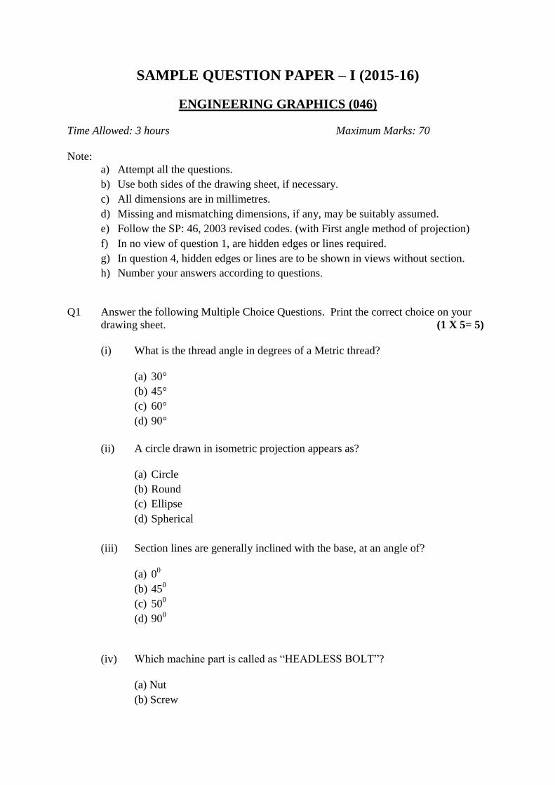
FEATHER KEY WITH GIB HEAD ON BOTH ENDS: 5
(i) Sketching front view 2
(ii) Sketching top view and side view 2
(iii)Standard dimensions 1
Q 4 ASSEMBLY OF PROTECTED FLANGE COUPLING

(a) FRONT VIEW, LOWER HALF IN SECTION 14
Drawing lower half of both flanges with hatching. 4
Drawing both shafts with conventional ends. 2
Drawing both keys as per given positions. 2
Drawing nut bolt assembly in lower half. 3
Drawing upper half of both flanges. 3
(b) SIDE VIEW, VIEWING FROM THE LEFT HAND SIDE 8
Drawing six circles(3) with hatching(1) in shaft as per convention 31/2
Drawing pitch circle diameter and at least one nut-bolt in lower half. 3
Drawing both keys with cutting plane. 11/2
(c) DETAILS. 6
Printing title (1), scale used (1), drawing projection symbol (1)
and printing six dimensions (3).
OR
DIS-ASSEMBLY OF SLEEVE & COTTER JOINT:
(a) SLEEVE 15
(i) Front View.
Drawing upper half in section. 5
Drawing lower half without section. 3
(ii) Side View with cutting plane. 7
(b) COTTER 7
(i) Front View. 4
(ii) Top View. 3
(c) DETAILS. 6
Printing title (1), scale used (1), drawing projection symbol (1)
and printing six dimensions (3).


SAMPLE QUESTION PAPER – II (2015-16)
ENGINEERING GRAPHICS (046)
Time Allowed: 3 hours Maximum Marks: 70
Note:
a) Attempt all the questions.
b) Use both sides of the drawing sheet, if necessary.
c) All dimensions are in millimetres.
d) Missing and mismatching dimensions, if any, may be suitably assumed.
e) Follow the SP: 46, 2003 revised codes. (with First angle method of projection)
f) In no view of question 1, are hidden edges or lines required.
g) In question 4, hidden edges or lines are to be shown in views without section.
h) Number your answers according to questions.
Q1 Answer the following Multiple Choice Questions. Print the correct choice on your
drawing sheet. (1 X 5= 5)
(i) A square lamina in isometric projection appears as?
(a) Rhombus
(b) Rectangle
(c) Trapezium
(d) Parallelogram
(ii) The width of a key „w‟ (as per standard dimensions) for a shaft of diameter
d = 60mm is
(a) 10mm
(b) 15mm
(c) 20mm
(d) 30mm
(iii) In first angle projection the order of object, plane and observer, as viewed
from the front is?
(a) Object, Plane and Observer
(b) Object, Observer and Plane
(c) Plane, Observer and Object
(d) Observer, Object and Plane

(iv) What is the thread angle in degrees of a BSW thread?
(a) 55°
(b) 60°
(c) 65°
(d) 75°
(v) Which type of rod-joint is used for rods of square cross section?
(a) Sleeve & Cotter Joint
(b) Socket and Spigot Joint
(c) Gib and Cotter Joint
(d) Knuckle Joint
Q2 (a) Construct an isometric scale. 4
(b) Draw the isometric projection of frustum of a hexagonal pyramid (top hexagonal
edge = 25mm, base hexagonal edge = 40mm, height=70mm) with a pair of base
edges parallel to V.P. and its axis perpendicular to the H.P. Give all the dimensions
and indicate the direction of viewing. 8
(c) A triangular prism (base edge = 45mm and height = 60mm) is placed centrally on
the top circular face of the plate (diameter = 80mm and axis = 30mm). The
triangular prism is resting on its base with one base edge parallel to V.P. and near to
it. The axis of both solids is perpendicular to V.P. Draw the isometric projection of
this combination of solids. Give the common axis, dimensions and indicate the
direction of viewing. 12
Q3 (a) Draw to scale 1:1, the standard profile of a Metric Screw Thread (external), taking
enlarged pitch 50 mm. Give standard dimensions. 8
OR
Draw to scale 1:1, the front view and top view of a Square Bolt of nominal diameter
24mm, keeping axis vertical. Give standard dimensions.
(b) Sketch free hand the front view and top view of a Pan head rivet of 30mm diameter.
Keep its axis vertical. Give standard dimensions. 5
OR
Sketch free hand the front view and side view of a stud with square neck of size
M20, keeping its axis horizontal. Give standard dimensions.

Q4 The Fig-1 shows details of the parts of a Turnbuckle. Assemble the parts correctly by
inserting 50mm threaded portion of each rod inside the body of Turnbuckle and draw
the following orthographic views to scale 1:1:
(a) Front View, upper half in section. 15
(b) Side view looking from the left end. 7
(c) Print Title and scale used. Draw Projection symbol. Give 6 important dimensions.
6
OR
The Fig-2 shows the assembly of Bushed Bearing. Dis-assemble the parts, and draw
orthographic views of the following parts to scale 1:1, keeping same position:
(a) BODY 15
(i) Front View, right half in section.
(ii) Top View.
(b) BUSH 7
(i) Front View, left half in section.
(ii) Top View.
(c) Give 6 important dimensions, Title, Projection symbol and Scale. 6


SAMPLE QUESTION PAPER – II
VALUE POINTS
Q1 MULTIPLE CHOICE QUESTIONS
(i) a 1
(ii) b 1
(iii) d 1
(iv) a 1
(v) c 1
Q2 (a) ISOMETRIC SCALE : 4
(i) Marking of divisions of 10 mm, including division of first part of 1
mm on true length.
1
(ii) Projections from scale 1:1 to get points on isometric scale,
construction of isometric scale.
2
(iii) Printing „True Length/Scale 1:1‟, „Isometric Length/Isometric Scale‟
and marking angles of 30 o & 45
o.
1
(b) ISOMETRIC PROJECTION OF FRUSTUM OF A HEXAGONAL
PYRAMID: 8
(i) Drawing helping figure of both hexagons. 11/2
(ii) Drawing isometric hexagons, on top and at the base. 3
(iii) Drawing slant edges. 1
(iv) Marking the vertical axis, direction of viewing. 1
(v) Dimensions. 11/2

(c) ISOMETRIC PROJECTION OF COMBINATION OF SOLIDS: 12
(i) Helping figure of triangle 1
(ii) Drawing both isometric ellipses 3
(iii) Drawing vertical lines of circular plate 1
(iv) Drawing isometric triangles, on top and at the base 2
(v) Drawing vertical lines indicating the faces of prism 2
(vi) Common Axis, direction of viewing 1
(vii) Dimensioning 2

Q3 (a) METRIC THREAD (EXTERNAL): 8
(i) Distance equal to pitch, and angles of 60o
2
(ii) Flat edges and curves for threads 2
(iii) Side edges / flanks and hatching 2
(iv) Standard Dimensions 2
OR
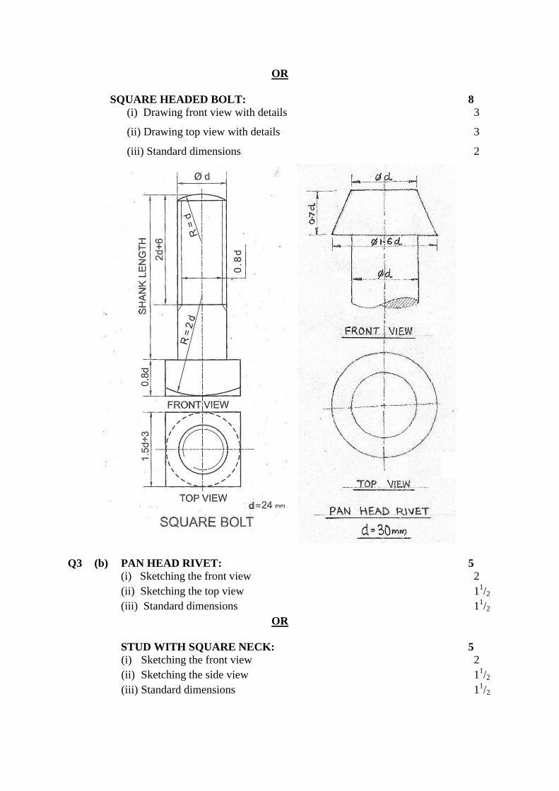
SQUARE HEADED BOLT: 8
(i) Drawing front view with details 3
(ii) Drawing top view with details 3
(iii) Standard dimensions 2
Q3 (b) PAN HEAD RIVET: 5
(i) Sketching the front view 2
(ii) Sketching the top view 11/2
(iii) Standard dimensions 11/2
OR
STUD WITH SQUARE NECK: 5
(i) Sketching the front view 2
(ii) Sketching the side view 11/2
(iii) Standard dimensions 11/2

Q4 TURNBUCKLE(Assembly)
28
(a) FRONT VIEW (Upper Half in Section) : 15
(i) Drawing lower half portion of the body. 4
(ii) Drawing upper half portion of the body, with hatching lines. 5
(iii) Drawing both rods with 50 mm inserted portion of each, showing
threads and hatching lines at the rod ends.
6
(b) SIDE VIEW (viewed from left) : 7
(i) Drawing three thick circles, one broken circle as per convention and
hatching lines.
41/2
(ii) Drawing dotted lines to indicate hidden portion. 2
(iii) Cutting plane.
1/2
(c) DETAILS :
Printing title (1), scale used (1), drawing projection symbol (1)
and printing six dimensions (3).
6
OR
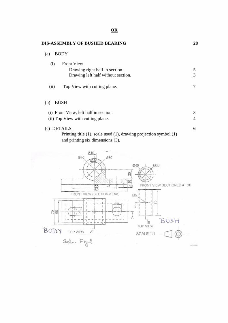
DIS-ASSEMBLY OF BUSHED BEARING 28
(a) BODY
(i) Front View.
Drawing right half in section. 5
Drawing left half without section. 3
(ii) Top View with cutting plane. 7
(b) BUSH
(i) Front View, left half in section. 3
(ii) Top View with cutting plane. 4
(c) DETAILS. 6
Printing title (1), scale used (1), drawing projection symbol (1)
and printing six dimensions (3).


![Isoperimetric Pentagonal · PDF filediscoveredby the now famous housewife Marjorie Rice[R],featuredinDorisSchattschneider’sarticle ... Isoperimetric Pentagonal Tilings Our](https://img.pdfslide.us/doc/110x75/5aa465c17f8b9a517d8bdc91/isoperimetric-pentagonal-the-now-famous-housewife-marjorie-ricerfeaturedindorisschattschneidersarticle.jpg)


![[E-Book] - Pentagonal Domain Exchange - Shigeki Akiyama and Edmind Harriss](https://img.pdfslide.us/doc/110x75/55cf9324550346f57b9c1ae4/e-book-pentagonal-domain-exchange-shigeki-akiyama-and-edmind-harriss.jpg)