Embed Size (px)
Citation preview

Sample Model
Highlights In-Flight Entertainment
v1.0

1 / 1 / Foreword
The system used as an example in this model does not reflect any existing Thales product. It is an overly simplified vision of what a real in-flight entertainment system is.
This model is partial, and mainly designed for educational purposes.
For any question about Arcadia or Capella, please post a question in the forum or use the contact addresses available on the Capella website.
Forum:
https://polarsys.org/forums/index.php/f/10/
Website:
http://www.polarsys.org/capella

2 / 2 / Document Objectives, Legend and Revision Table
Method or engineering
highlights
Capella tips and tricks The objective of this document is to browse the sample IFE model through the 5 Arcadia engineering steps.
These slides mainly rely on extracts of diagrams and form a kind of “reading path” through the model.
Noteworthy tooling, engineering or method aspects are highlighted throughout the document.
Version Date Author(s) Notes
1.0 Feb 24th, 2015 Stéphane Bonnet (Thales) Initialization

3 / 3 / Operational Analysis
What the users of the system
need to accomplish
OA
SA
LA
PA
EPBS

4 / 4 / Main Drivers for Operational Analysis
The Operational Analysis is partial and minimal in this version. It basically introduces what kind of activities are performed by the Cabin Crew and the Passengers.
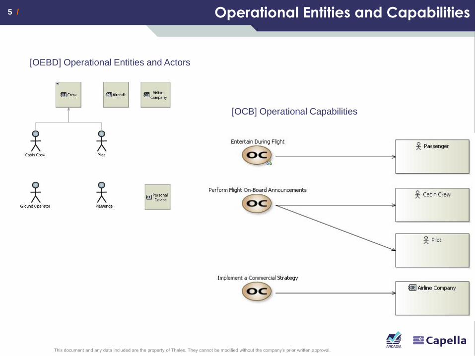
5 / 5 / Operational Entities and Capabilities
[OEBD] Operational Entities and Actors
[OCB] Operational Capabilities

6 / 6 / High-Level Expected Activities
[OAB] High-Level Expected Activities
[OAIB] Watch Movie

7 / 7 / Overview of all Operational Entities and Activities
[OAB] All Operational Activities and Entities

8 / 8 / Operational Processes
[OPD] Perform Audio Announcement
[OAB] All Operational Activities and Entities

9 / 9 / Operational Context: Flying Phases
[M&S] Aircraft Flying Phases
[OES] Flight Phases
The state machine is defined on the
“Aircraft” Operational Entity.
The scenario is defined on the
« Entertain During Flight »
Operational Capability

10 / 10 / System Need Analysis
What the system has to
accomplish for the users
OA
SA
LA
PA
EPBS

11 / 11 / Main Drivers for System Need Analysis
Not all the IFE system is modelled. Focus is put on VOD service, audio announcement and imposed videos (safety instructions, ads, etc.).
While interesting, the topic of the integration of the IFE with the aircraft is kept minimal (according to flying conditions, the IFE system is supposed to behave differently).
Not all possible Scenarios and Functional Chains have been created.
The system is globally organized as follows:
Cabin crew services are always available, passenger services have to be activated. Their availability depends on the flying conditions and on the class the passengers are flying in
The system is able to store digital media content
Most of the interactions of the passengers with their services (navigating between menus, selecting movies, etc.) are captured in functions called “Run <xxx> service”
Services rely on audio and video broadcast means
Maintenance and configuration topics are only evoked

12 / 12 / System Missions and Capabilities
[MCB] Capabilities

13 / 13 / System Missions and Capabilities
[CM] Provide Cabin Management Solutions
The content of contextual Mission and
contextual Capability diagrams is
computed automatically.
[CC] Provide Audio and Video Intercommunication Means

14 / 14 / System Missions and Capabilities
[SC] System Actors
The aircraft is an Actor of the IFE
system even though the system is
inside the aircraft. This is because the
Aircraft is providing information and
means to the IFE.

15 / 15 / Top-Level Dataflow: The System, The Actors
[SDFB] Top Level Functional Overview

16 / 16 / System Overview: An Entry Point to Functional Analysis
[SAB] Top Level System Overview The SAB diagram is
often a very entry
point to the model.
The idea is to
display high-level
Functions, and
navigate / zoom
inside the Functions
to explore in greater
detail the functional
analysis.

17 / 17 / System Overview
Composite functions have their name
in italic. Explore their internal content
by navigating on the diagram
describing them.

18 / 18 / System Overview: Slightly Refined View

19 / 19 / OA-SA Difference: Focus on Audio Announcements
In Operational Analysis, cabin crew is
performing audio announcement.
But in System Need Analysis, the cabin
crew actor does not have a
corresponding Function.
Rationale: Audio announcements are
safety critical and cannot be dependent
of the IFE. Audio announcements are
performed through the aircraft hardware,
even though the IFE system is still
responsible for diplaying an interruption
screen and for broadcasting the
announcement in the headphones of
each passenger.
The IFE actually receives an audio
stream from the aircraft (that will trigger
the interruption). The fact that the cabin
crew is actually performing the
announcement is out of scope.
[OAB] All Operational Activities and Entities
Semantic Browser on “Cabin Crew” System Actor
[SAB] High Level System Overview

20 / 20 / Capability-Based Organization
[SDFB] [CAPABILITY] Provide Audio and
Video Intercommunication Means
[SDFB] [CAPABILITY] Provide
Video Entertainment Services
Capabilities are usually a organizational unit for
models: They can be used to distribute
responsibilities between different
contributors, they are useful when
planning IV&V campaigns, etc.

21 / 21 / Capability-Based Organization
Displaying or creating Functions in a
Dataflow diagram attached to a
Capability automatically creates
reference/exploitation relationships
from the Capability to the
Functions. This improves
later impact analyses.
An easy way to display all Functions
involved in a Capability is to use the
modeling accelerators allowing to
display at once all Functional Chain
and Scenario elements.

22 / 22 / Functional Breakdown
… [SFBD] All System Functions
[SFBD] All Actor Functions
Function breakdown
are typically generated
on the basis of the
work performed in
dataflow diagrams.
Avoiding to mix
System and Actor
functions in the same
hierarchy is a good
practice.

23 / 23 / Dictionary / Domain Model
[CDB] In-Flight Entertainment Dictionary
The data exchanged between Functions and between
the System and the Actors could already be
formalized in the System Need Analysis step. This is
not the case in this sample model, the goal of this
independent domain model is to give a
small idea of the concepts the system
will use / fits in.

24 / 24 / Layout Pattern
Keeping the layout consistent across
diagram is a good way to improve
diagram readability

25 / 25 / Contextual Dataflow Diagrams
In this model, all diagram illustrating the internal content of a fonction are
prefixed by [CTX]. The contextual elements (the one on which refresh rules
are based) are in bold.
Diagram can be set contextual to elements using the property view.
Most of these
diagrams have been
set as
unsynchronized, in
order to only display
what is relevant to
the current context.
See the
documentation.

26 / 26 / Functional Chains & Scenarios (1/2)
[SFCD] Watch Imposed Video on Private Screen Functional Chains and Scenarios are specific paths
use cases, they illustrate the Capabilities.
In order to be important asset for the global
engineering picture (see Arcadia), creating them is
a good way to check the design completeness.
Functional Chains can be displayed
in dataflow diagrams and architecture
diagrams.

27 / 27 / Functional Chains & Scenarios (2/2)
[FS] Perform Audio Announcement
3 main kind of Scenarios:
• Function Scenarios (lifeline = Functions)
• Exchange Scenario (lifelines = component and actors)
• Interface Scenarios (sequence messages are Exchange Items)
Capella provide automated Initializations from one to another
[ES] Perform Audio Announcement

28 / 28 / System Global Modes
Relate the transitions
and states to other
elements of the model.
Warning: Capella is not
restrictive enough in the
choices it proposes
and validation is not
complete either.
ONGOING WORK
[M&S] IFE Operating Modes

29 / 29 / Other Mode Machine: The Seat TV
[M&S] Seat TV Modes

30 / 30 / Traceability with Operational Analysis
Traceability is partially created when performing automated transitions from
Operational Analysis to System Need Analysis.
The remaining part has to be created manually, using element
property editors or dedicated matrices.

31 / 31 / Logical Architecture
How the system will work so as
to fulfill the expectations
OA
SA
LA
PA
EPBS
OA
SA
LA
PA
EPBS

32 / 32 / Transitions from System Need Analysis
Use transition tools
to initialize the
design at Logical
Architecture level
(Functions, Actors,
Scenarios, etc.).
Use the Diagram
content creation
accelerator.

33 / 33 / Design choices for Logical Architecture
Architecture driver #1
Organization of the architecture in 4 main parts in order to take into account the topology of the aircraft and anticipate integration concerns:
Front Servers + Cabin Terminal for Cabin Crew and Maintenance
Distribution network
Private TV on Seats
Cabin Screens
Architecture driver #2
Functional grouping in order to reduce interfaces, optimize performance, etc.
Architecture driver #3
Architecture patterns are implemented to anticipate product customisation and product line policy.
Product Customisation: Aircraft- and airline-specific functionality are segregated in separated components in order to be easily removed / replaced.
Product Line Policy : Currently not illustrated in this sample model (requires a Variability viewpoint).
Modeling choice: No network modelling
While it is obvious all communications will ultimately go through a network, this is ignored at this stage.

34 / 34 / Definition of Architecture Drivers
[LCBD] Architecture Drivers

35 / 35 / Logical Components
[LAB] IFE System - All Components, CEs

36 / 36 / Functional Analysis Refinement (1/3)
[LFBD] All Functions
The new Functions can either be created directly from the breakdown diagram
either be created while refining dataflow diagrams. Here, the
Functions added at Logical level have been marked in flashy green.

37 / 37 / Functional Analysis Refinement - Examples (2/3)
Description of how
Description of how
SA
SA
LA
LA
Design decision: Creation of a
generic interface with the aircraft

38 / 38 /
Other example: The high level function in charge of managing the audio and video diffusion is split
in 4 sub functions: process/analyze the requests, broadcast existing digital media, broadcast live
audio (audio announcements) and display/play the video/audio streams. Each of these Functions
are further decomposed.
[LDFB] [CTX] Manage Audio and Video Diffusion
Functional Analysis Refinement – Examples (3/3)

39 / 39 / Allocation of Functions to Components
[LAB] [BUILD] Template To improve
productivity, it is often
interesting to brush
layout from one
diagram to another or
to clone diagrams.
Here, a template has
been created and is
used for a few other
architecture diagrams.

40 / 40 / Different Purposes for Different Diagrams
[LAB] [BUILD] All Components, Functions, CEs, FEs Not all diagrams are
intended to be published.
Some diagrams only exist
temporarily for building or
analysing purposes.
Such diagrams have been
marked in this model with
the tag [BUILD].
Here, the diagrams is a
clone of the template where
all Functions and all
exchanges are displayed.
While not adapted to
publication, it is useful to
check the design, visualize
Functional Chains, etc.

41 / 41 / Refinement of Functional Chains
The Functional Chains obtained after the automated transition
will most likely be incomplete/invalid after the functional
analysis refinement.
Fixing the Functional Chains at Logical Level is a mandatory
task, which often leads to fixing inconsistencies in the
functional refinement.
Functional Chains are a powerful way to ensure the
design completeness.
SA LA
[SFCD] Watch Imposed Movie on Cabin Screen [LFCD] Watch Imposed Video on Cabin Screen

42 / 42 / Rapid Creation of Contextual Diagrams
[LAB][CTX] Watch
Imposed Video on
Cabin Screen FC
How to quickly obtain this LAB diagram?
1. Clone the LAB template, remove all Functions
2. Set the diagram to be contextual to the Functional Chain, perform a diagram refresh
3. In the original LAB template diagram, copy the layout
4. Paste the layout in current diagram
5. Arrange the Functional Exchanges routing, remove unnecessary Components

43 / 43 / Refinement of Scenarios (1/2)
Use automated transitions to initialize the design of Logical Scenarios
Correct and enrich the result with the existing Functions and Functional Exchanges or create
the missing ones.
[ES] Start Playing VOD Movie [ES] Start Playing VOD Movie
SA LA To be enriched and completed
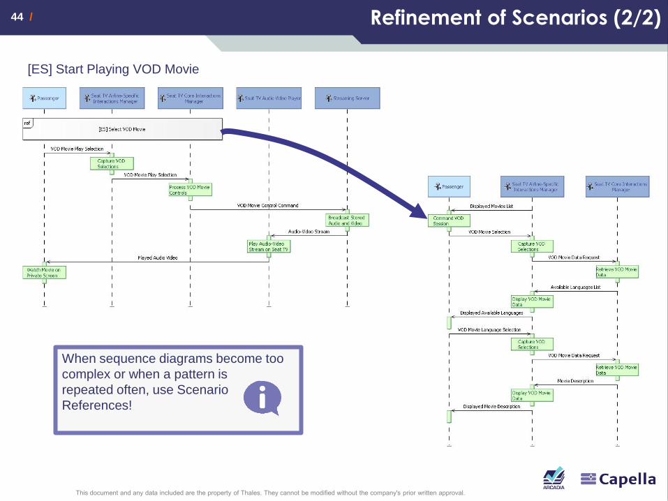
44 / 44 / Refinement of Scenarios (2/2)
When sequence diagrams become too
complex or when a pattern is
repeated often, use Scenario
References!
[ES] Start Playing VOD Movie
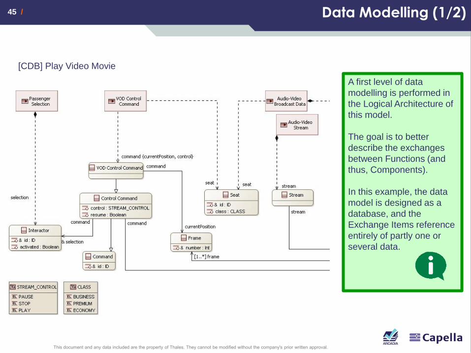
45 / 45 / Data Modelling (1/2)
[CDB] Play Video Movie
A first level of data
modelling is performed in
the Logical Architecture of
this model.
The goal is to better
describe the exchanges
between Functions (and
thus, Components).
In this example, the data
model is designed as a
database, and the
Exchange Items reference
entirely of partly one or
several data.

46 / 46 / Data Modelling (2/2)
[CDB] Play Video Movie
Exchange Items are used
to relate Data and
Functional Exchanges.
For example, it is the only
mean to express that two
distinct Functional
Exchange actually carry
the same of common data
[LAB][CTX] Start Playing VOD Movie FC
In dataflow and
architecture diagrams,
filters allow to display the
names of the carried
Exchange Items instead of
the Functional Exchanges
labels

47 / 47 / Seat TV Modes (1/2)
[M&S] Seat TV - Movie Player Modes

48 / 48 / Seat TV Modes (2/2)
Capella does not provide
means (yet) to really
formalize the guards in
Transitions.
However, it provides a
constraint-based
mechanism allowing to
keep references between
model elements (use
CTRL-SPACE when
editing constraints). If the
name of the Enumeration
Literal changes, the Guard
will be kept
synchronized.

49 / 49 / Physical Architecture
How the system will be
developed and built
OA
SA
LA
PA
EPBS

50 / 50 / Physical Architecture
The interactions of the Passenger with the Seat TV are performed through a remote control
The interactions of the cabin crew with the Central Management Unit are based on a Touch Screen
The modelling of the network is kept minimal:
In an IFE, the network distribution is an essential aspect (one of the goals is to reduce the length – and mass – of the network cables). This is not covered in this model where all switches are represented by one single component
No network routing functions. The only the setup and configuration basic Functions are created
Streaming is a bit more detailed, without encompassing what would be the responsibility of the SW subsystems. The chosen stopping criterion is to be able to perform basic latency non-functional analysis.
The replication of streaming servers is not (yet) modelled. Scenarios and Mode machines have not been propagated (they should be).

51 / 51 / Implementation Components (1/2)
[PAB] Implementation and Behaviour Components

52 / 52 / Physical Architecture – Implementation Components (2/2)
Interactions based on a remote
control on passenger side
Touch Screen for Cabin Crew
No intelligence in
cabin displays
Dedicated audio and
video processors

53 / 53 / Physical Architecture – Behaviour Components (1/2)
[PCBD] Behavioral Components

54 / 54 / Physical Architecture – Behaviour Components (2/2)
[PCBD] Behavioral Components
Breakdown to take into
account the HW components:
DAC and audio/video
dedicated processors
Breakdown to take into account
concerns which were ignored in
Logical Architecture: Network, Screens
Breakdown to take into
account the choice of relying
on a remote control rather
than on a Touch Screen for
the Seat TV

55 / 55 / Implementation and Behaviour Components
[PAB] Implementation and Behaviour Components

56 / 56 / Refinement of Functional Analysis (1/2)
Several drivers for Functional Analysis refinement.
Topics not covered in Logical Architecture (Network, Screens, etc.)
and further description of specific topics (management of audio and
video streams)
[PFBD] All Physical Functions

57 / 57 / Refinement of Functional Analysis (2/2)
[PDFB] [CTX] Broadcast Audio Video Stream to Seat TV
One of the drivers for
refining the Functional
Analysis here is to add
enough detail about the
streaming mechanisms, in
order to be able to perform
non-functional analysis later
on (for example, latency
analyses).
Simplified streaming steps
(packeting, etc.) are
therefore described.
[PDFB] [CTX] Broadcast Audio and Video Streams

58 / 58 / Refinement (and Composition) of Functional Chains
[PFCD] Resume VOD Movie [PFCD] Start Playing VOD Movie
[PFCD] Broadcast VOD Movie

59 / 59 / Mapping Functions / Components, Physical Path
The PVDU architecture is
based on an internal bus
connecting the processor, the
media decoders and the DAC.
The BUS is modeled with a
specific Implementation
Component and a Physical
Path linking all the elements
connected to the BUS.
Here, the packets exchanged
between the player and the
decoder go through the
"Packet Transmission"
Component Exchange. The
Component Exchange is
transported by the "PVDU
BUS" Physical Path.

60 / 60 / [BUILD] Working Diagrams
Building diagrams
Template. To gain in
productivity, it is often
interesting to brush layout
from one diagram to
another or to clone
diagrams. Here, a
template has been created
and is used for a few other
architecture diagrams.
All PCs, PFs, FEs. The
diagram is a clone of the
template where all
Functions and all
exchanges are displayed.
While not adapted to
publication, it is useful to
check the design, visualize
Functional Chains, etc.
[PAB] [BUILD] All PCs, PFs, FEs
[PAB] [BUILD] Template

61 / 61 / Management of Network Components (1/4)
The Network adapter is present on
several components, with the same
functionality.
Instead of modelling several time
the same thing, the Replicable
Elements mechanisms are used.
Definition (REC) and instances
(RPLs) can be kept synchronized.

62 / 62 / Management of Network Components (2/4)
Usage of REC-RPL
mechanisms.
A REC is created and is
instantiated several times.
When no dedicated library is
used, the organization of the
model tree has to be carefully
defined, in order to distinguish
between “types” and
“instances”.
The REC content is in the
model, but somehow isolated
from the other elements (it
could be in a library).
The connection between the
RPLs are managed manually
(ONGOING work in Capella).
REC
RPL

63 / 63 / Management of Network Components (3/4)
[PAB] Focus on Network Setup, Configuration and Tests
REC - Unit Network Adapter RPL - Instantiations of Unit Network Adapter

64 / 64 / Management of Network Components (4/4)
Illustration of the network
carrying exchanges.
There is no added-value in
this model in modelling the
functional part of the transport
over the network. Only
network setup and
configuration is modelled.
The transport between
components are modelled with
Physical Links. Here, the
Physical Path "Network Path"
is set to transport the
Component Exchange
"Streaming Protocol", showing
that all packets between
"Send" and "Split" Functions
as well as the stream Header
actually go through the
Ethernet network and
switches.

65 / 65 / Refinement of Data Model (1/3)
Refinement of the data
model:
- New streaming concepts
taken into account, such
as packets, stream
headers, codecs, etc.
- Unlike the data model in
Logical Architecture, the
(arbitrary) choice is
made here not to rely on
a database-like design
but on standalone types
(constraint of the
targeted SW
environment)

66 / 66 / Refinement of Data Model (2/3)
In the current version of the model, the data modelling has only been performed
partly, focusing on the “Start Playing Video Movie” Functional Chain
[PAB] [CTX] Start Playing VOD Movie FC

67 / 67 / Refinement of Data Model (3/3)
Capella provides means to generate a first
version of the interfaces of a component based
on the incoming/outgoing Component
Exchanges, Functional Exchanges, Exchange
Items.
[CDI] Streaming Server

68 / 68 / Definition/justification of Interfaces: Summary
Use semantic Browser to
navigate between these
concepts & relations
Functional exchanges & ports carry Exchange items
Exchange items group
data to be carried
together
Interfaces group &
reference Exchange items
Functional
exchanges &
ports are
allocated to
component
exchanges &
ports
Component
exchanges & ports
are allocated to
Physical links/paths
& ports
Interfaces are
provided/required by
Component Ports

69 / 69 / EPBS
What is expected from each
designer / sub-contractor
OA
SA
LA
PA
EPBS

70 / 70 / EPBS
Several drivers can orient the choices for Configuration Items. One goal of EPBS is to define an architectural frame to master component development and integration.
In this sample model, different rationales:
Group all streaming SW components into one single Configuration Item
Group all airline-specific SW components into one single Configuration Item
Create all Network setup and configuration SW into one single Configuration Item
Have a Non Developed Configuration Item all network equipment and cables
Etc.

71 / 71 / Examples of Configuration Items
[EAB] Configuration Items and Realized Artefacts

72 / 72 / Next Steps
Considered future evolutions for this
sample model
Multi-viewpoint analysis, including
Reliability analysis, with replication of video servers
Sizing (network)
Mass
Refinement of Modes/States modelling (enhancement of the relationship with functions and functional exchanges)
(Automated) transition towards subsystem
Completeness + functional scope enrichment

73 / 73 / Questions
Questions on this model?
Use the Arcadia Forum:
https://polarsys.org/forums/index.php/f/12/

74 / 74 / Call for Contribution
Feel like contributing?
Directly submit us your enrichments
Contact us to converge on a specific scope