Embed Size (px)
DESCRIPTION
handbook mastercam
Citation preview
This page intentionally blankMastercam Handbook Volume 1 for Mastercam X6
Copyright © 1984 - 2012 In-House Solutions Inc. - All rights reserved. Software: Mastercam X6 Mill & Solids Authors: In-House Solutions Inc. ISBN: 978-1-926955-45-2 Revision Date: February 7, 2012 Notice
In-House Solutions Inc. reserves the right to make improvements to this manual at any time and without notice.
Disclaimer Of All Warranties And Liability
In-House Solutions Inc. makes no warranties, either express or implied, with respect to this manual or with respect to the software described in this manual, its quality, performance, merchantability, or fitness for any particular purpose. In-House Solutions Inc. manual is sold or licensed "as is." The entire risk as to its quality and performance is with the buyer. Should the manual prove defective following its purchase, the buyer (and not In-House Solutions Inc., its distributor, or its retailer) assumes the entire cost of all necessary servicing, repair, of correction and any incidental or consequential damages. In no event will In-House Solutions Inc. be liable for direct, indirect, or consequential damages resulting from any defect in the manual, even if In-House Solutions Inc. has been advised of the possibility of such damages. Some jurisdictions do not allow the exclusion or limitation of implied warranties or liability for incidental or consequential damages, so the above limitation or exclusion may not apply to you.
Copyrights
This manual is protected under the copyright laws of Canada and the United States. All rights are reserved. This document may not, in whole or part, be copied, photocopied, reproduced, translated or reduced to any electronic medium or machine readable form without prior consent, in writing, from In-House Solutions Inc.
Trademarks
Mastercam is a registered trademark of CNC Software, Inc. Microsoft, the Microsoft logo, MS, and MS-DOS are registered trademarks of Microsoft Corporation; Windows2000, Windows XP and Windows 7, are registered trademarks of Microsoft Corporation. This document complies with Mastercam-X6 as of February 2012. Requires Mastercam Mill Level 1. Requires Solids for Chapter 5


Contents
Introduction
Chapter 1 Computer Essentials
Chapter 2 Mastercam Workspace
Chapter 3 CAD Drawing
Chapter 4 Advanced CAD Drawing
Chapter 5 Solid Modeling
Chapter 6 Drill Toolpaths
Chapter 7 Contour Toolpaths
Chapter 8 Pocket Toolpaths
Chapter 9 2d High Speed and FBM
Chapter 10 Rotary Toolpaths
Chapter 11 Change Recognition
App. A Drill Charts
App. B G&M Codes
App. C Speeds and Feeds

Icons
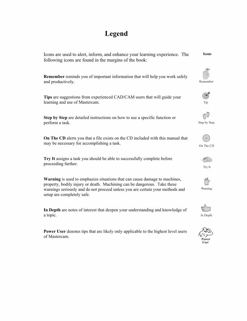
Legend Icons are used to alert, inform, and enhance your learning experience. The following icons are found in the margins of the book: Remember reminds you of important information that will help you work safely and productively. Tips are suggestions from experienced CAD/CAM users that will guide your learning and use of Mastercam. Step by Step are detailed instructions on how to use a specific function or perform a task. On The CD alerts you that a file exists on the CD included with this manual that may be necessary for accomplishing a task. Try It assigns a task you should be able to successfully complete before proceeding further. Warning is used to emphasize situations that can cause damage to machines, property, bodily injury or death. Machining can be dangerous. Take these warnings seriously and do not proceed unless you are certain your methods and setup are completely safe. In Depth are notes of interest that deepen your understanding and knowledge of a topic. Power User denotes tips that are likely only applicable to the highest level users of Mastercam.

Conventions
Key words and Mastercam menu items are shown in bold the first time they are used. Columns on the outside edges of each page and note pages at the end of each chapter provide ample space for taking notes. Useful tips, recommended settings, best practices, and detailed instruction on the most important features are included when possible.
Common Terms
The following terms are used throughout this book. Left Click means to click once on the left mouse button. Click means the same as left click. Right Click means to click once on the right mouse button. Scroll means to roll the mouse scroll wheel, or move the scroll index in a list. Options are Mastercam functions selected from the main menu. Enter means to select the <Enter> key on your computer keyboard. Press means to press on a keyboard key. Choose means to select a menu option or button. Open/Close means to open or close a dialog or information box. Dialog Box is a window that opens to allow input of information and setting of defaults. Drop Down/Fly Out Menus are menus that expand down, left, right, or up, to reveal more menu lists. A Function is the same as a menu option or command. Help means the Mastercam help files loaded with your software.
Drill Toolpaths
Mastercam Handbook Volume 1 6-1
Objectives
Introduction
This chapter introduces drill toolpaths and functions used to create and verify CNC programs. When finished with this chapter, you should be able to:
Select a Machine Type. Define stock size, material type, and other job related parameters. Select geometry for drilling operations. Use tool and material libraries. Understand and properly set drill parameters including cycle type, speed
and feed, cut depth, and rapid height. Verify the toolpath and make changes as needed. Post process the program to create an NC code. Transmit the NC file to the CNC machine using RS-232
communications. Hole-making is the most fundamental and widely used machining operation. In this chapter, you will learn to program holes using wireframe entities —going from a blank screen to NC code. After drawing or importing geometry, you will select a Machine Type. You then set up a Work Coordinate System (WCS) so Mastercam knows the location and orientation of the part in relation to the machine. You then set Toolpath Properties, which include material type and size. Next, you will pick geometry that defines the hole locations, then set Toolpath Parameters including speed, feed, coolant, and offset number. You will then set Drill Parameters including fixed cycle type, clearance, rapid and cut depths. After Mastercam calculates the toolpath, you simulate the drilling processes and check for problems. If necessary, you will change geometry, drill sequence, or parameters until the program is correct. Finally, you will select the Mastercam Post Process function to create an NC program that is communicated to your machine to make the part.
Drill Toolpaths 6
Chapter 6
Mastercam X6 6-2
Mastercam Programming
Process
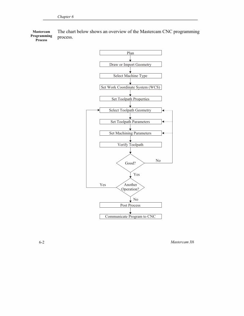
The chart below shows an overview of the Mastercam CNC programming process.
Communicate Program to CNC
Good?
Yes
No
AnotherOperation?
No
Yes
Plan
Select Machine Type
Draw or Import Geometry
Set Work Coordinate System (WCS)
Set Toolpath Properties
Select Toolpath Geometry
Set Toolpath Parameters
Set Machining Parameters
Verify Toolpath
Post Process
Drill Toolpaths
Mastercam Handbook Volume 1 6-3
Plan. Decide how the part will be held, order of machining operations, and tools to use. Draw or Import Geometry. Programs begin with geometry that describes the finish dimensions of the part. Create the geometry from a part print or import it from another CAD/CAM system. Select Machine Type. Select a Machine and Control definition that matches your CNC machine tool. Set Work Coordinate System (WCS). Set the machining coordinate system to locate and align the part with the machine tool. Set Toolpath Properties. Set the file locations, tool settings, stock size, material type, and safety zone. Select Toolpath Geometry. Select geometry representing the finish dimensions of the feature to machine. Set Toolpath Parameters. Tool parameters include tool type, diameter, and cutting speed and feed. Set Machining Parameters. Machining parameters include clearance, rapid, retract, final depth, step down, and step over values. Verify Toolpath. Carefully check your toolpaths before proceeding. If the results are good, proceed to the next operation. If not, change Geometry, Tool Parameters or Machining Parameters and regenerate the toolpath until you are satisfied with the results. Post Process. Post processor act like a kind of language translator, transforming your machining operations into a usable CNC program. Communicate Program to CNC. Transfer the NC program to the CNC machine via RS-232 communications, floppy disk, flash memory or Ethernet link.
Chapter 6
Mastercam X6 6-4
Drill Tools
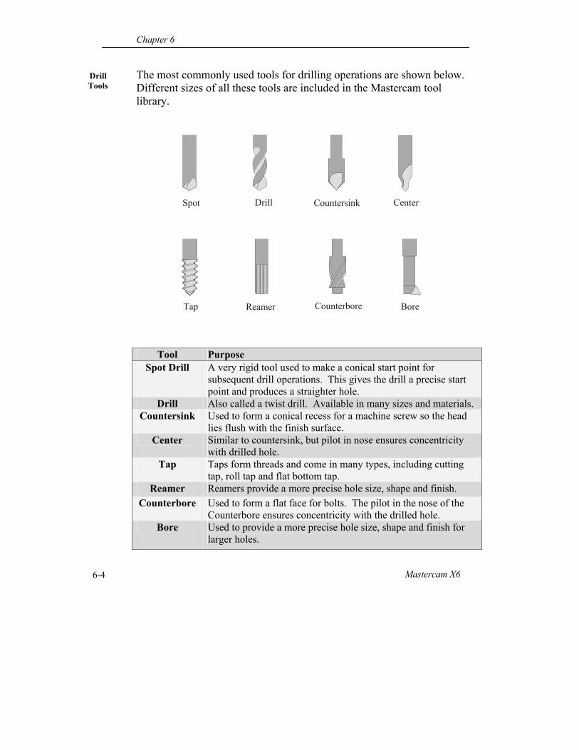
The most commonly used tools for drilling operations are shown below. Different sizes of all these tools are included in the Mastercam tool library.
Tool Purpose Spot Drill A very rigid tool used to make a conical start point for
subsequent drill operations. This gives the drill a precise start point and produces a straighter hole.
Drill Also called a twist drill. Available in many sizes and materials. Countersink Used to form a conical recess for a machine screw so the head
lies flush with the finish surface. Center Similar to countersink, but pilot in nose ensures concentricity
with drilled hole. Tap Taps form threads and come in many types, including cutting
tap, roll tap and flat bottom tap. Reamer Reamers provide a more precise hole size, shape and finish.
Counterbore Used to form a flat face for bolts. The pilot in the nose of the Counterbore ensures concentricity with the drilled hole.
Bore Used to provide a more precise hole size, shape and finish for larger holes.
BoreReamerTap Counterbore
Spot Drill Center Countersink
Drill Toolpaths
Mastercam Handbook Volume 1 6-5
Drill Tool
Selection
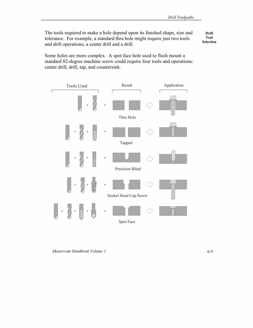
The tools required to make a hole depend upon its finished shape, size and tolerance. For example, a standard thru hole might require just two tools and drill operations; a center drill and a drill. Some holes are more complex. A spot face hole used to flush mount a standard 82-degree machine screw could require four tools and operations: center drill, drill, tap, and countersink.
Tapped
Precision Blind
Socket Head Cap Screw
Spot Face
+ =+
Thru Hole
+ + =+
+ =+
+ =+
=+
Tools Used Result Application
Chapter 6
Mastercam X6 6-6
Machine Type
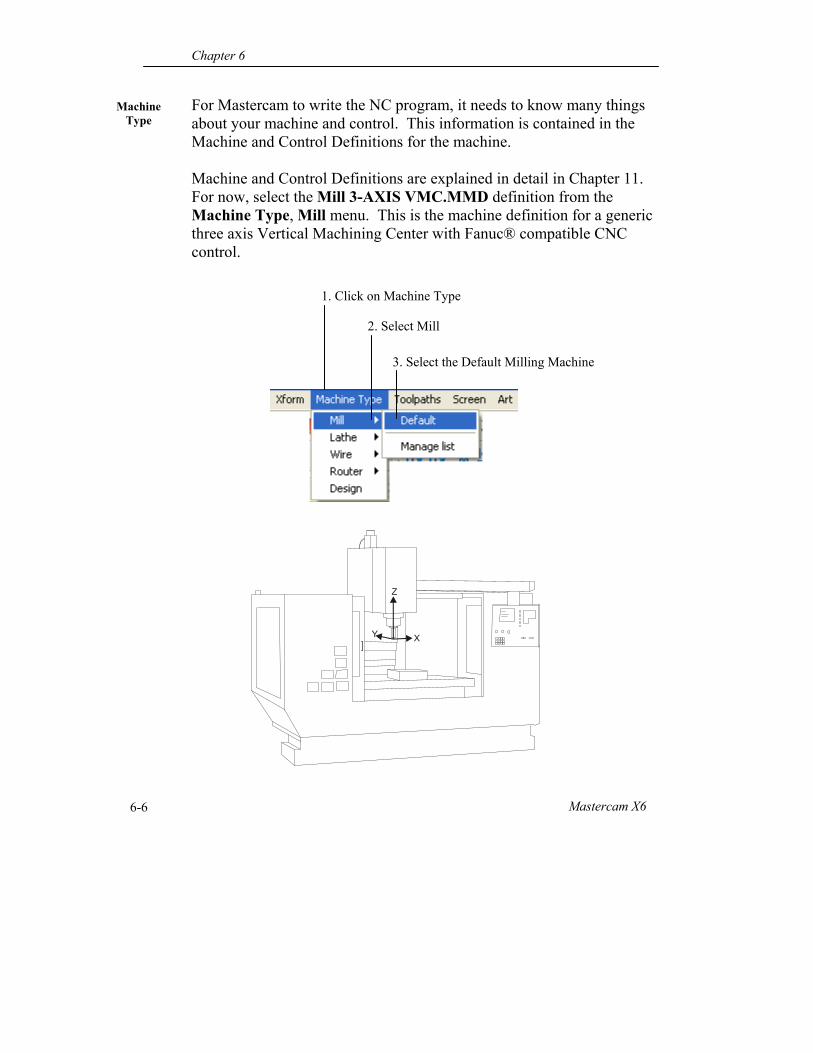
For Mastercam to write the NC program, it needs to know many things about your machine and control. This information is contained in the Machine and Control Definitions for the machine. Machine and Control Definitions are explained in detail in Chapter 11. For now, select the Mill 3-AXIS VMC.MMD definition from the Machine Type, Mill menu. This is the machine definition for a generic three axis Vertical Machining Center with Fanuc® compatible CNC control.
X
Z
Y
1. Click on Machine Type
2. Select Mill
3. Select the Default Milling Machine
Drill Toolpaths
Mastercam Handbook Volume 1 6-7
Work Coordinate
System (WCS)
Most parts require multiple setups. For example, a part may be first set up and machined on one side. It may then be flipped up in the vise, a new machining datum set, and machined on that side. Most parts require at least two setups, and some require many more -typically one setup and datum for each side machined. As the part is moved and flipped between setups, both the CNC machine and Mastercam must know the location of and orientation of the new machining datum. This is done using the Mastercam Work Coordinate System (WCS). Think of the WCS as a kind of Cplane for toolpaths. Rather than using the Mastercam Xform functions to move and rotate the part to align it with the Mastercam coordinate system, the WCS lets you set up a machining coordinate system. This machining coordinate system lets Mastercam know where the datum for the part (Work Offset) is located on the part, and how the part is oriented in relation to the machine XY axis and spindle. The WCS offers the following advantages over moving the part using Xform: Imported parts stay in the same coordinate system location as they were
drawn in CAD. This is a requirement for many aerospace companies when the part is located in airplane space, or where it is installed on the aircraft. This location is often far from the Mastercam Coordinate System datum and not aligned with the coordinate system axes.
WCS controls machine Fixture Offsets. Most post processors are set up to change the fixture offset (G54, G55, etc.) based on the WCS work offset setting.
All machining processes can be simulated in the same session. If you move the part for each operation, you can only simulate one setup at a time. Use the WCS to simulate machining processes that work on multiple sides of the part.
Revisions are easier. New versions of the part are easier update if the part stays in the same location and orientation as the previous version. Mastercam’s Change Recognition technologies require the original and incoming parts be in the same position.
Chapter 6
Mastercam X6 6-8
Pre-Defined WCS
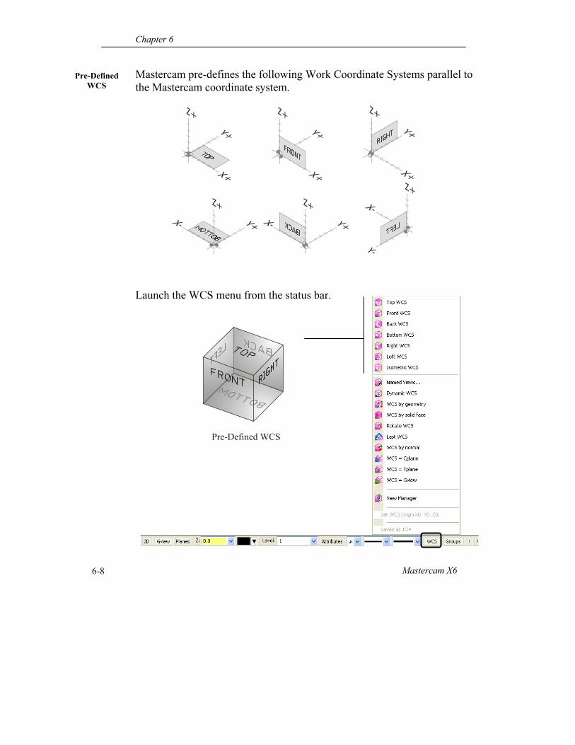
Mastercam pre-defines the following Work Coordinate Systems parallel to the Mastercam coordinate system. Launch the WCS menu from the status bar.
Pre-Defined WCS
Drill Toolpaths
Mastercam Handbook Volume 1 6-9
User-Defined WCS
User Defined WCS
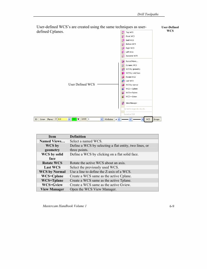
User-defined WCS’s are created using the same techniques as user-defined Cplanes.
Item Definition Named Views… Select a named WCS.
WCS by geometry
Define a WCS by selecting a flat entity, two lines, or three points.
WCS by solid face
Define a WCS by clicking on a flat solid face.
Rotate WCS Rotate the active WCS about an axis. Last WCS Select the previously used WCS.
WCS by Normal Use a line to define the Z-axis of a WCS. WCS=Cplane Create a WCS same as the active Cplane. WCS=Tplane Create a WCS same as the active Tplane. WCS=Gview Create a WCS same as the active Gview.
View Manager Open the WCS View Manager.
Chapter 6
Mastercam X6 6-10
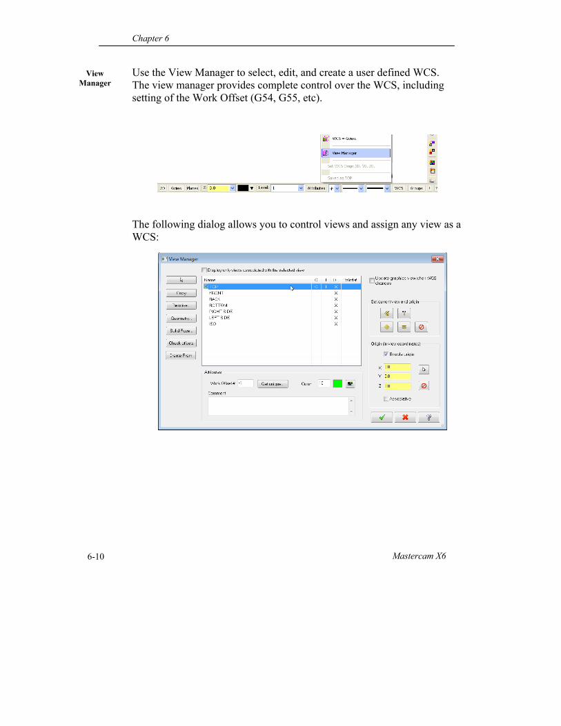
View Manager
Use the View Manager to select, edit, and create a user defined WCS. The view manager provides complete control over the WCS, including setting of the Work Offset (G54, G55, etc). The following dialog allows you to control views and assign any view as a WCS:
Drill Toolpaths
Mastercam Handbook Volume 1 6-11
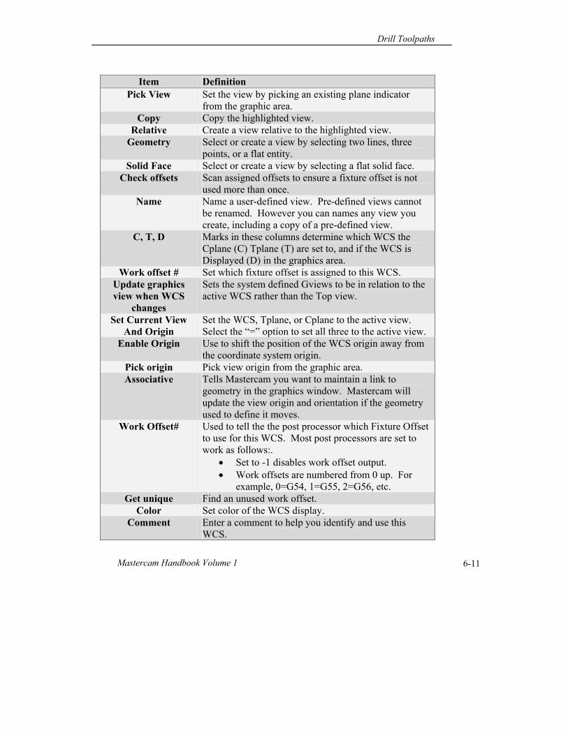
Item Definition Pick View Set the view by picking an existing plane indicator
from the graphic area. Copy Copy the highlighted view.
Relative Create a view relative to the highlighted view. Geometry Select or create a view by selecting two lines, three
points, or a flat entity. Solid Face Select or create a view by selecting a flat solid face.
Check offsets Scan assigned offsets to ensure a fixture offset is not used more than once.
Name Name a user-defined view. Pre-defined views cannot be renamed. However you can names any view you create, including a copy of a pre-defined view.
C, T, D Marks in these columns determine which WCS the Cplane (C) Tplane (T) are set to, and if the WCS is Displayed (D) in the graphics area.
Work offset # Set which fixture offset is assigned to this WCS. Update graphics view when WCS
changes
Sets the system defined Gviews to be in relation to the active WCS rather than the Top view.
Set Current View And Origin
Set the WCS, Tplane, or Cplane to the active view. Select the “=” option to set all three to the active view.
Enable Origin Use to shift the position of the WCS origin away from the coordinate system origin.
Pick origin Pick view origin from the graphic area. Associative Tells Mastercam you want to maintain a link to
geometry in the graphics window. Mastercam will update the view origin and orientation if the geometry used to define it moves.
Work Offset# Used to tell the the post processor which Fixture Offset to use for this WCS. Most post processors are set to work as follows:.
Set to -1 disables work offset output. Work offsets are numbered from 0 up. For
example, 0=G54, 1=G55, 2=G56, etc. Get unique Find an unused work offset.
Color Set color of the WCS display. Comment Enter a comment to help you identify and use this
WCS.
Chapter 6
Mastercam X6 6-12
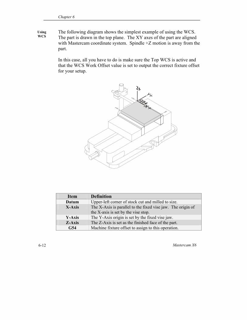
Using WCS
The following diagram shows the simplest example of using the WCS. The part is drawn in the top plane. The XY axes of the part are aligned with Mastercam coordinate system. Spindle +Z motion is away from the part. In this case, all you have to do is make sure the Top WCS is active and that the WCS Work Offset value is set to output the correct fixture offset for your setup.
Item Definition Datum Upper-left corner of stock cut and milled to size. X-Axis The X-Axis is parallel to the fixed vise jaw. The origin of
the X-axis is set by the vise stop. Y-Axis The Y-Axis origin is set by the fixed vise jaw. Z-Axis The Z-Axis is set as the finished face of the part.
G54 Machine fixture offset to assign to this operation.
Drill Toolpaths
Mastercam Handbook Volume 1 6-13
Using WCS
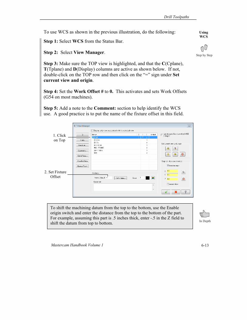
To use WCS as shown in the previous illustration, do the following:
Step 1: Select WCS from the Status Bar. Step 2: Select View Manager. Step 3: Make sure the TOP view is highlighted, and that the C(Cplane), T(Tplane) and D(Display) columns are active as shown below. If not, double-click on the TOP row and then click on the “=” sign under Set current view and origin. Step 4: Set the Work Offset # to 0. This activates and sets Work Offsets (G54 on most machines). Step 5: Add a note to the Comment: section to help identify the WCS use. A good practice is to put the name of the fixture offset in this field.
To shift the machining datum from the top to the bottom, use the Enable origin switch and enter the distance from the top to the bottom of the part. For example, assuming this part is .5 inches thick, enter -.5 in the Z field to shift the datum from top to bottom.
2. Set Fixture Offset
1. Click on Top
Chapter 6
Mastercam X6 6-14
User-Defined WCS
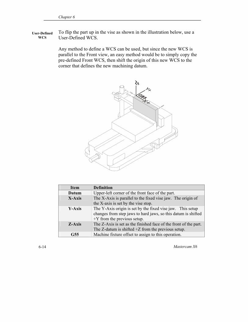
To flip the part up in the vise as shown in the illustration below, use a User-Defined WCS. Any method to define a WCS can be used, but since the new WCS is parallel to the Front view, an easy method would be to simply copy the pre-defined Front WCS, then shift the origin of this new WCS to the corner that defines the new machining datum.
Item Definition Datum Upper-left corner of the front face of the part. X-Axis The X-Axis is parallel to the fixed vise jaw. The origin of
the X-axis is set by the vise stop. Y-Axis The Y-Axis origin is set by the fixed vise jaw. This setup
changes from step jaws to hard jaws, so this datum is shifted +Y from the previous setup.
Z-Axis The Z-Axis is set as the finished face of the front of the part. The Z-datum is shifted +Z from the previous setup.
G55 Machine fixture offset to assign to this operation.
Drill Toolpaths
Mastercam Handbook Volume 1 6-15
Copy WCS
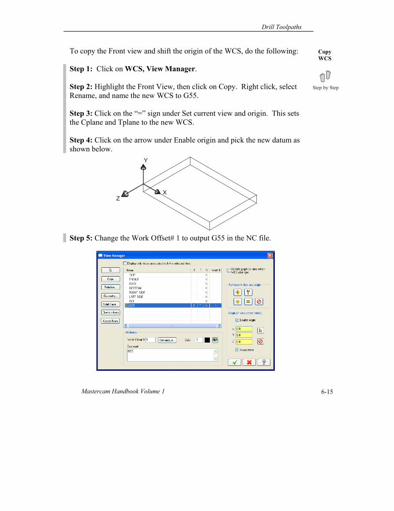
To copy the Front view and shift the origin of the WCS, do the following: Step 1: Click on WCS, View Manager. Step 2: Highlight the Front View, then click on Copy. Right click, select Rename, and name the new WCS to G55. Step 3: Click on the “=” sign under Set current view and origin. This sets the Cplane and Tplane to the new WCS. Step 4: Click on the arrow under Enable origin and pick the new datum as shown below. Step 5: Change the Work Offset# 1 to output G55 in the NC file.
XZ
Y
Chapter 6
Mastercam X6 6-16
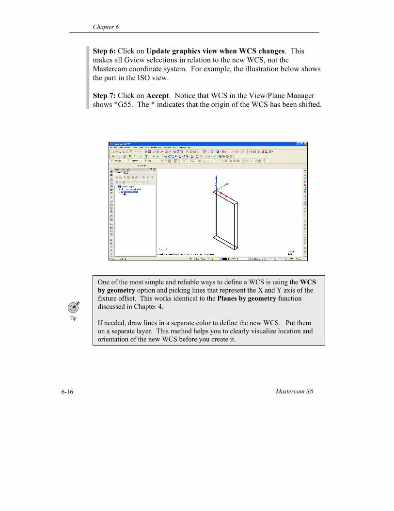
Step 6: Click on Update graphics view when WCS changes. This makes all Gview selections in relation to the new WCS, not the Mastercam coordinate system. For example, the illustration below shows the part in the ISO view. Step 7: Click on Accept. Notice that WCS in the View/Plane Manager shows *G55. The * indicates that the origin of the WCS has been shifted.
One of the most simple and reliable ways to define a WCS is using the WCS by geometry option and picking lines that represent the X and Y axis of the fixture offset. This works identical to the Planes by geometry function discussed in Chapter 4. If needed, draw lines in a separate color to define the new WCS. Put them on a separate layer. This method helps you to clearly visualize location and orientation of the new WCS before you create it.
Drill Toolpaths
Mastercam Handbook Volume 1 6-17
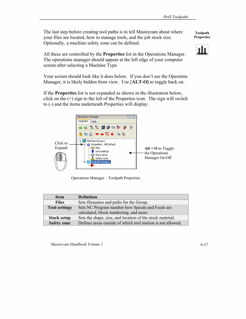
Toolpath Properties
The last step before creating tool paths is to tell Mastercam about where your files are located, how to manage tools, and the job stock size. Optionally, a machine safety zone can be defined. All these are controlled by the Properties list in the Operations Manager. The operations manager should appear at the left edge of your computer screen after selecting a Machine Type. Your screen should look like it does below. If you don’t see the Operatins Manager, it is likely hidden from view. Use [ALT-O] to toggle back on. If the Properties list is not expanded as shown in the illustration below, click on the (+) sign to the left of the Properties icon. The sign will switch to (-) and the items underneath Properties will display.
Item Definition Files Sets filenames and paths for the Group.
Tool settings Sets NC Program number how Speeds and Feeds are calculated, block numbering, and more.
Stock setup Sets the shape, size, and location of the stock material. Safety zone Defines areas outside of which tool motion is not allowed.
Operations Manager – Toolpath Properties
Alt + O to Toggle the Operations Manager On/Off
Click to Expand
Chapter 6
Mastercam X6 6-18
Properties- Files
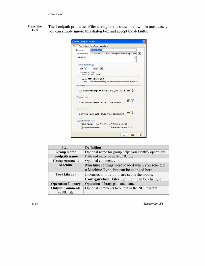
The Toolpath properties Files dialog box is shown below. In most cases, you can simply ignore this dialog box and accept the defaults.
Item Definition Group Name Optional name for group helps you identify operations.
Toolpath name Path and name of posted NC file. Group comment Optional comments.
Machine Machine settings were loaded when you selected a Machine Type, but can be changed here.
Tool Library Libraries and defaults are set in the Tools, Configuration, Files menu but can be changed.
Operation Library Operations library path and name. Output Comments
to NC file Optional comments to output in the NC Program.
Drill Toolpaths
Mastercam Handbook Volume 1 6-19
Properties- Tool settings
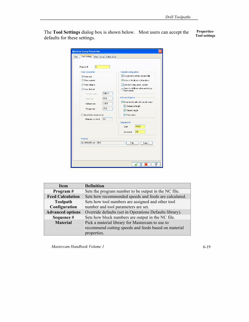
The Tool Settings dialog box is shown below. Most users can accept the defaults for these settings.
Item Definition Program # Sets the program number to be output in the NC file.
Feed Calculation Sets how recommended speeds and feeds are calculated. Toolpath
Configuration Sets how tool numbers are assigned and other tool number and tool parameters are set.
Advanced options Override defaults (set in Operations Defaults library). Sequence # Sets how block numbers are output in the NC file.
Material Pick a material library for Mastercam to use to recommend cutting speeds and feeds based on material properties.
Chapter 6
Mastercam X6 6-20
Properties- Stock setup
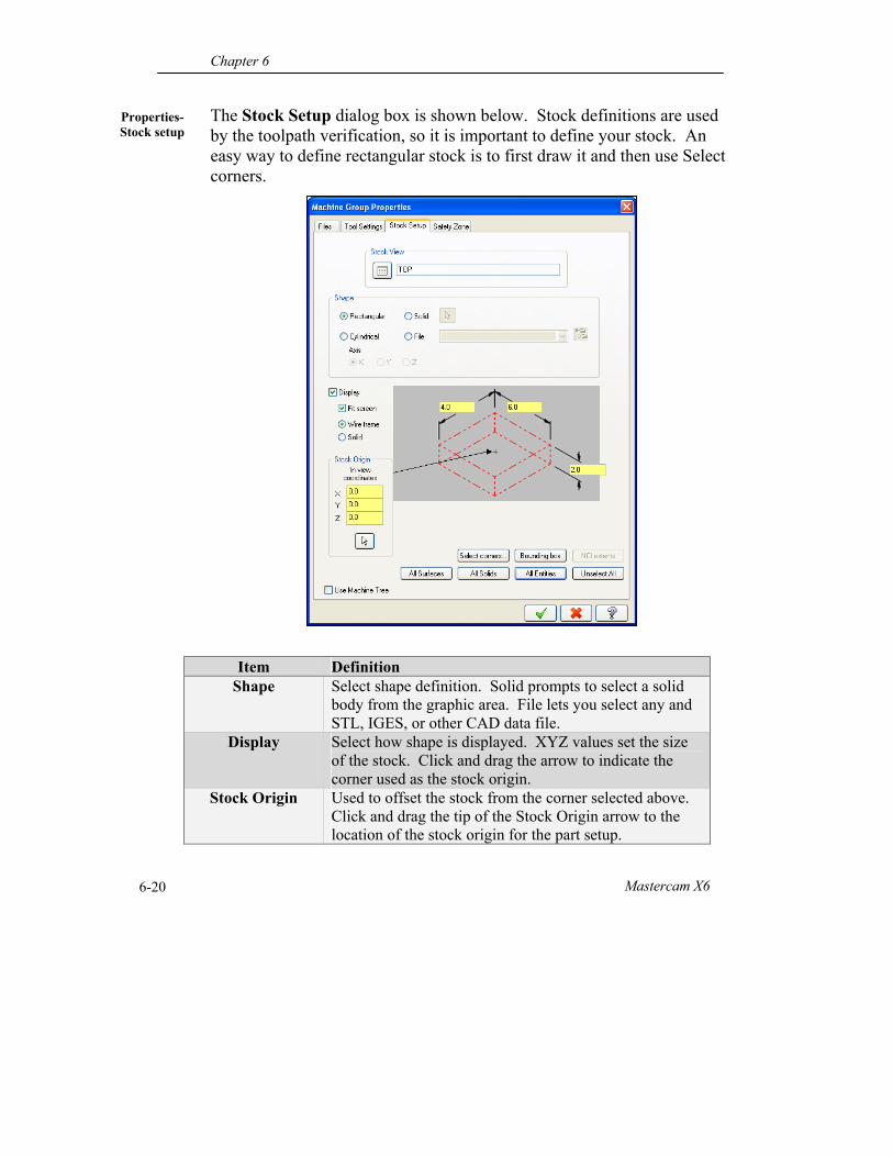
The Stock Setup dialog box is shown below. Stock definitions are used by the toolpath verification, so it is important to define your stock. An easy way to define rectangular stock is to first draw it and then use Select corners.
Item Definition Shape Select shape definition. Solid prompts to select a solid
body from the graphic area. File lets you select any and STL, IGES, or other CAD data file.
Display Select how shape is displayed. XYZ values set the size of the stock. Click and drag the arrow to indicate the corner used as the stock origin.
Stock Origin Used to offset the stock from the corner selected above. Click and drag the tip of the Stock Origin arrow to the location of the stock origin for the part setup.
Drill Toolpaths
Mastercam Handbook Volume 1 6-21
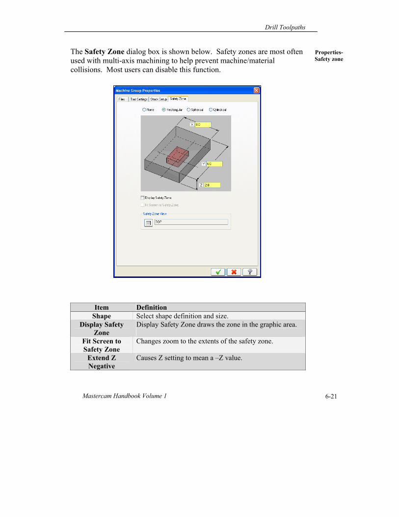
Properties- Safety zone
The Safety Zone dialog box is shown below. Safety zones are most often used with multi-axis machining to help prevent machine/material collisions. Most users can disable this function.
Item Definition Shape Select shape definition and size.
Display Safety Zone
Display Safety Zone draws the zone in the graphic area.
Fit Screen to Safety Zone
Changes zoom to the extents of the safety zone.
Extend Z Negative
Causes Z setting to mean a –Z value.
Chapter 6
Mastercam X6 6-22
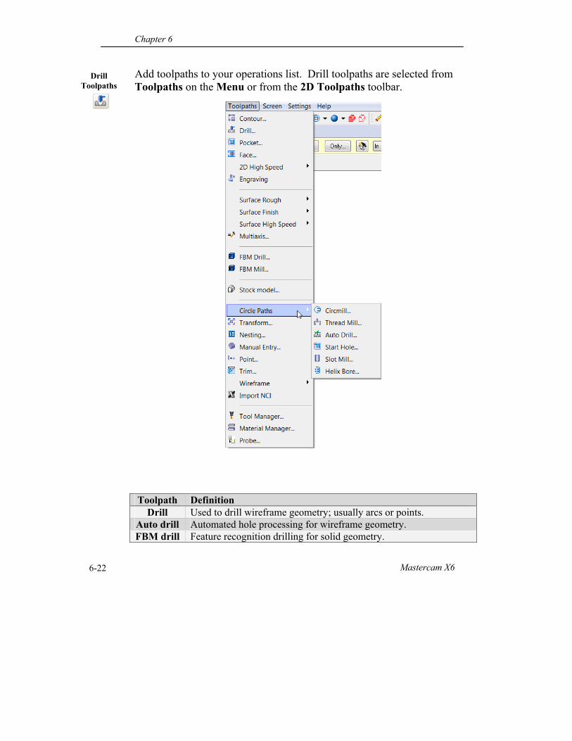
Drill Toolpaths
Add toolpaths to your operations list. Drill toolpaths are selected from Toolpaths on the Menu or from the 2D Toolpaths toolbar. Toolpath Definition
Drill Used to drill wireframe geometry; usually arcs or points. Auto drill Automated hole processing for wireframe geometry. FBM drill Feature recognition drilling for solid geometry.
Drill Toolpaths
Mastercam Handbook Volume 1 6-23
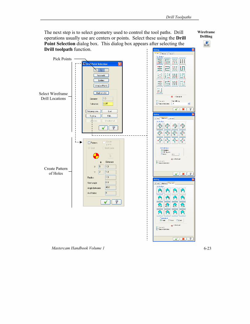
Wireframe Drilling
The next step is to select geometry used to control the tool paths. Drill operations usually use arc centers or points. Select these using the Drill Point Selection dialog box. This dialog box appears after selecting the Drill toolpath function.
Create Pattern of Holes
Select Wireframe Drill Locations
Pick Points
Chapter 6
Mastercam X6 6-24
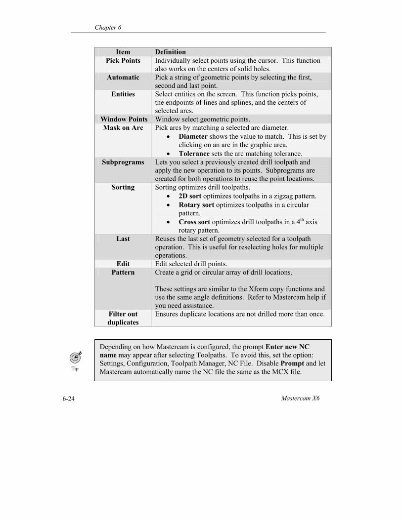
Item Definition Pick Points Individually select points using the cursor. This function
also works on the centers of solid holes. Automatic Pick a string of geometric points by selecting the first,
second and last point. Entities Select entities on the screen. This function picks points,
the endpoints of lines and splines, and the centers of selected arcs.
Window Points Window select geometric points. Mask on Arc Pick arcs by matching a selected arc diameter.
Diameter shows the value to match. This is set by clicking on an arc in the graphic area.
Tolerance sets the arc matching tolerance. Subprograms Lets you select a previously created drill toolpath and
apply the new operation to its points. Subprograms are created for both operations to reuse the point locations.
Sorting Sorting optimizes drill toolpaths. 2D sort optimizes toolpaths in a zigzag pattern. Rotary sort optimizes toolpaths in a circular
pattern. Cross sort optimizes drill toolpaths in a 4th axis
rotary pattern. Last Reuses the last set of geometry selected for a toolpath
operation. This is useful for reselecting holes for multiple operations.
Edit Edit selected drill points. Pattern Create a grid or circular array of drill locations.
These settings are similar to the Xform copy functions and use the same angle definitions. Refer to Mastercam help if you need assistance.
Filter out duplicates
Ensures duplicate locations are not drilled more than once.
Depending on how Mastercam is configured, the prompt Enter new NC name may appear after selecting Toolpaths. To avoid this, set the option: Settings, Configuration, Toolpath Manager, NC File. Disable Prompt and let Mastercam automatically name the NC file the same as the MCX file.
Drill Toolpaths
Mastercam Handbook Volume 1 6-25
Wireframe Drill
Locations
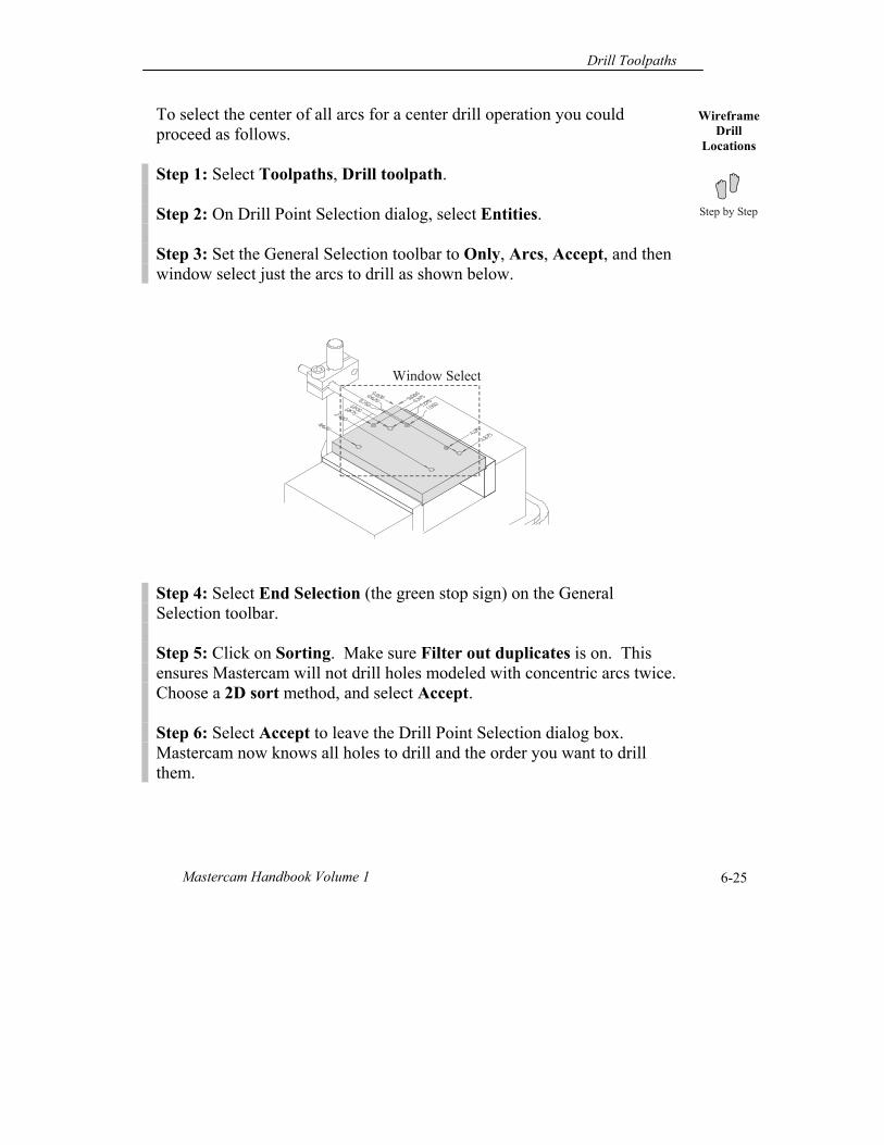
To select the center of all arcs for a center drill operation you could proceed as follows. Step 1: Select Toolpaths, Drill toolpath. Step 2: On Drill Point Selection dialog, select Entities. Step 3: Set the General Selection toolbar to Only, Arcs, Accept, and then window select just the arcs to drill as shown below. Step 4: Select End Selection (the green stop sign) on the General Selection toolbar. Step 5: Click on Sorting. Make sure Filter out duplicates is on. This ensures Mastercam will not drill holes modeled with concentric arcs twice. Choose a 2D sort method, and select Accept. Step 6: Select Accept to leave the Drill Point Selection dialog box. Mastercam now knows all holes to drill and the order you want to drill them.
Window Select
Chapter 6
Mastercam X6 6-26
Toolpath Type
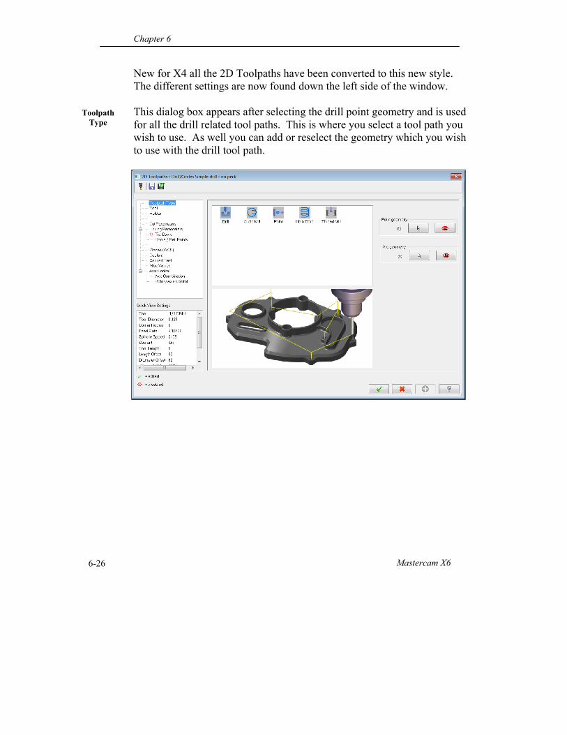
New for X4 all the 2D Toolpaths have been converted to this new style. The different settings are now found down the left side of the window. This dialog box appears after selecting the drill point geometry and is used for all the drill related tool paths. This is where you select a tool path you wish to use. As well you can add or reselect the geometry which you wish to use with the drill tool path.
Drill Toolpaths
Mastercam Handbook Volume 1 6-27
Tool
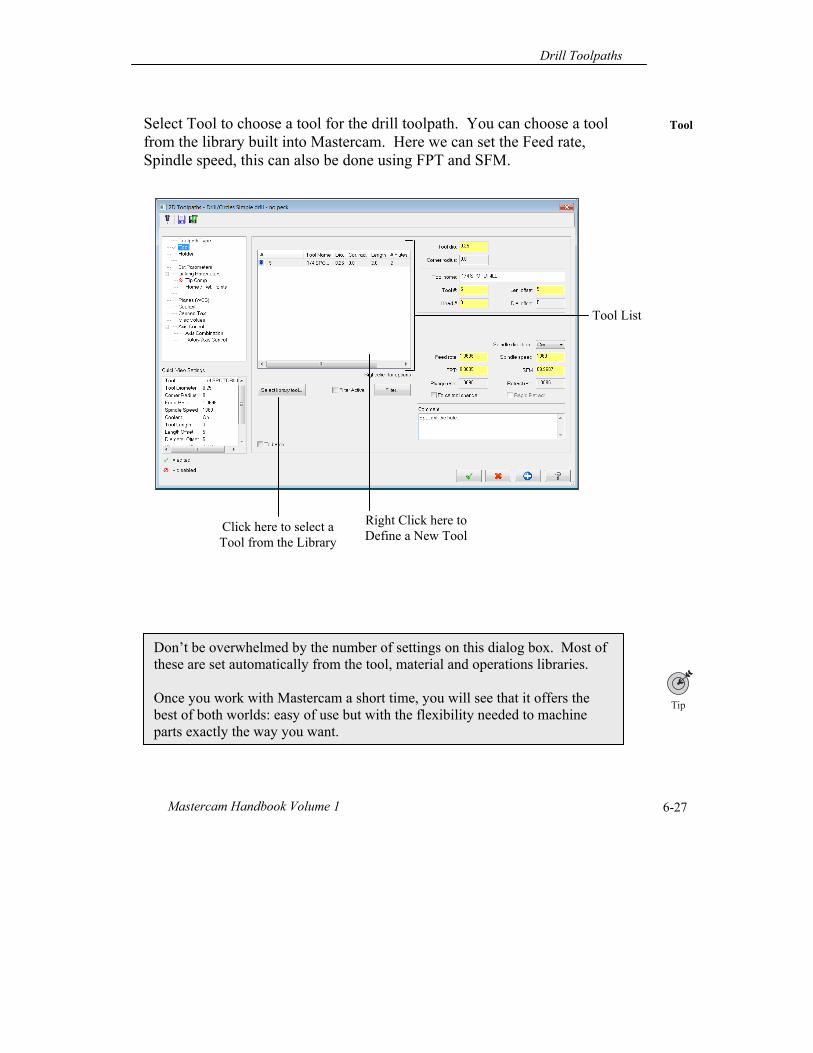
Select Tool to choose a tool for the drill toolpath. You can choose a tool from the library built into Mastercam. Here we can set the Feed rate, Spindle speed, this can also be done using FPT and SFM.
Don’t be overwhelmed by the number of settings on this dialog box. Most of these are set automatically from the tool, material and operations libraries. Once you work with Mastercam a short time, you will see that it offers the best of both worlds: easy of use but with the flexibility needed to machine parts exactly the way you want.
Right Click here to Define a New Tool
Tool List
Click here to select a Tool from the Library
Chapter 6
Mastercam X6 6-28
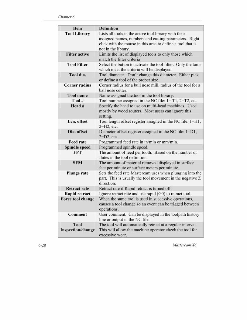
Item Definition Tool Library Lists all tools in the active tool library with their
assigned names, numbers and cutting parameters. Right click with the mouse in this area to define a tool that is not in the library.
Filter active Limits the list of displayed tools to only those which match the filter criteria
Tool Filter Select the button to activate the tool filter. Only the tools which meet the criteria will be displayed.
Tool dia. Tool diameter. Don’t change this diameter. Either pick or define a tool of the proper size.
Corner radius Corner radius for a bull nose mill, radius of the tool for a ball nose cutter.
Tool name Name assigned the tool in the tool library. Tool # Tool number assigned in the NC file: 1= T1, 2=T2, etc. Head # Specify the head to use on multi-head machines. Used
mostly by wood routers. Most users can ignore this setting.
Len. offset Tool length offset register assigned in the NC file: 1=H1, 2=H2, etc.
Dia. offset Diameter offset register assigned in the NC file: 1=D1, 2=D2, etc.
Feed rate Programmed feed rate in in/min or mm/min. Spindle speed Programmed spindle speed.
FPT The amount of feed per tooth. Based on the number of flutes in the tool definition.
SFM The amount of material removed displayed in surface feet per minute or surface meters per minute.
Plunge rate Sets the feed rate Mastercam uses when plunging into the part. This is usually the tool movement in the negative Z direction.
Retract rate Retract rate if Rapid retract is turned off. Rapid retract Ignore retract rate and use rapid (G0) to retract tool.
Force tool change When the same tool is used in successive operations, causes a tool change so an event can be trigged between operations.
Comment User comment. Can be displayed in the toolpath history line or output in the NC file.
Tool Inspection/change
The tool will automatically retract at a regular interval. This will allow the machine operator check the tool for excessive wear.
Drill Toolpaths
Mastercam Handbook Volume 1 6-29
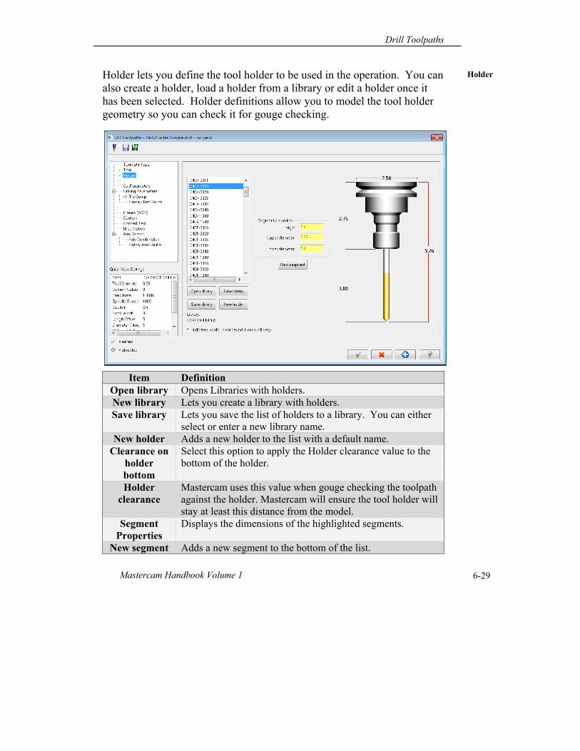
Holder lets you define the tool holder to be used in the operation. You can also create a holder, load a holder from a library or edit a holder once it has been selected. Holder definitions allow you to model the tool holder geometry so you can check it for gouge checking.
Item Definition Open library Opens Libraries with holders. New library Lets you create a library with holders. Save library Lets you save the list of holders to a library. You can either
select or enter a new library name. New holder Adds a new holder to the list with a default name.
Clearance on holder bottom
Select this option to apply the Holder clearance value to the bottom of the holder.
Holder clearance
Mastercam uses this value when gouge checking the toolpath against the holder. Mastercam will ensure the tool holder will stay at least this distance from the model.
Segment Properties
Displays the dimensions of the highlighted segments.
New segment Adds a new segment to the bottom of the list.
Holder
Chapter 6
Mastercam X6 6-30
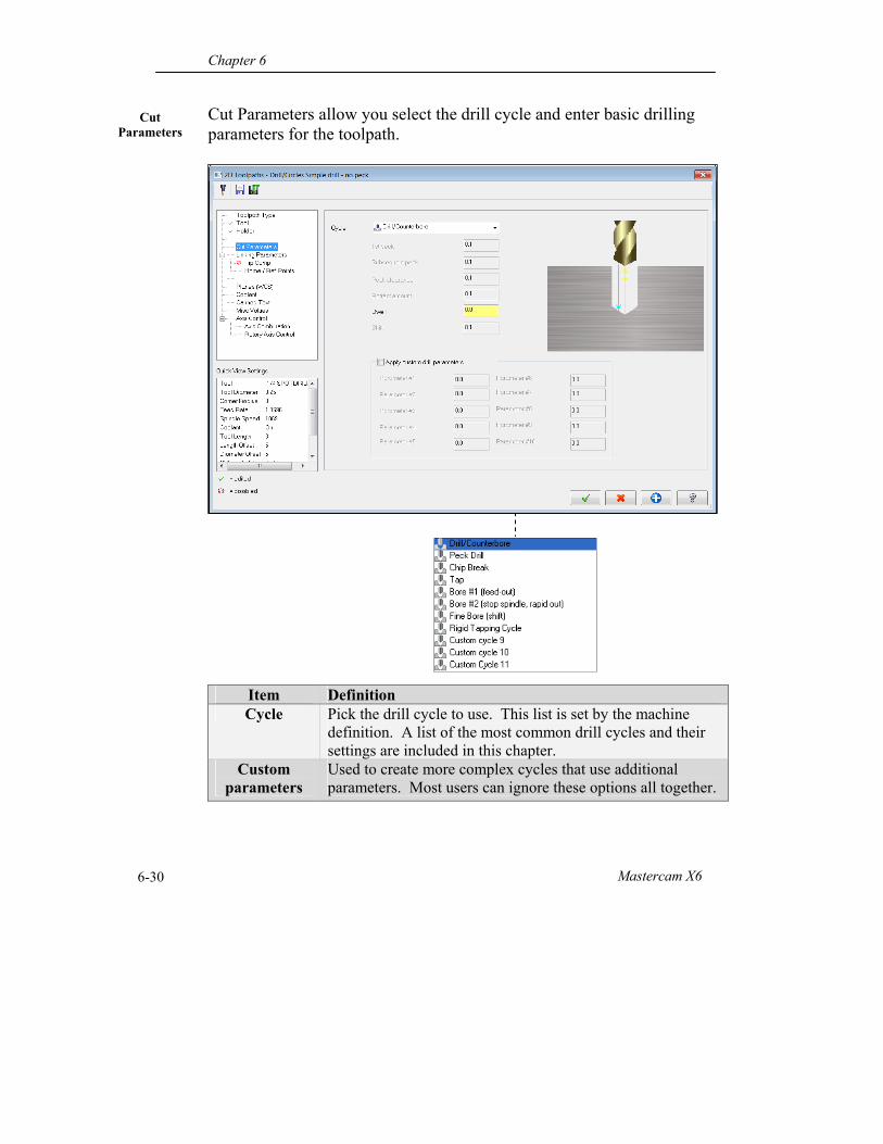
Cut Parameters allow you select the drill cycle and enter basic drilling parameters for the toolpath.
Item Definition Cycle Pick the drill cycle to use. This list is set by the machine
definition. A list of the most common drill cycles and their settings are included in this chapter.
Custom parameters
Used to create more complex cycles that use additional parameters. Most users can ignore these options all together.
Cut Parameters
Drill Toolpaths
Mastercam Handbook Volume 1 6-31
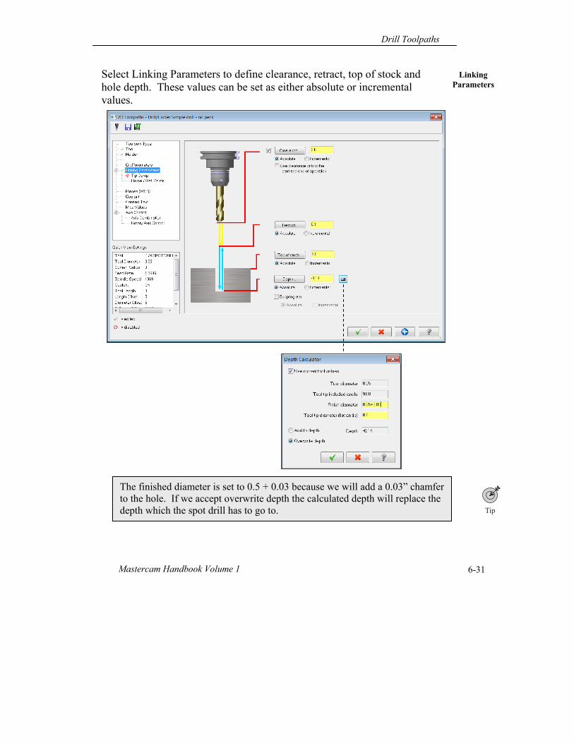
Linking Parameters
Select Linking Parameters to define clearance, retract, top of stock and hole depth. These values can be set as either absolute or incremental values.
The finished diameter is set to 0.5 + 0.03 because we will add a 0.03” chamfer to the hole. If we accept overwrite depth the calculated depth will replace the depth which the spot drill has to go to.
Chapter 6
Mastercam X6 6-32
To pick geometric points, distances, and angles from geometry in the graphic area, click on the button next to a field. For example, to set Depth, click on the Depth button. Mastercam will minimize the dialog box and allow you to select a geometry feature in the graphic area.
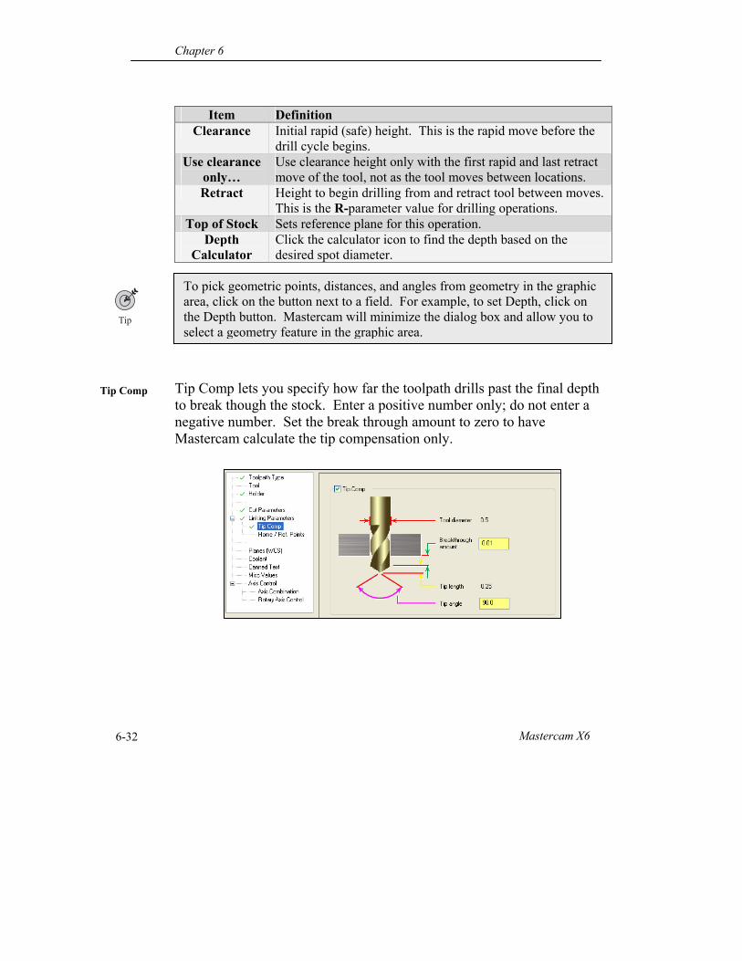
Tip Comp lets you specify how far the toolpath drills past the final depth to break though the stock. Enter a positive number only; do not enter a negative number. Set the break through amount to zero to have Mastercam calculate the tip compensation only.
Item Definition Clearance Initial rapid (safe) height. This is the rapid move before the
drill cycle begins. Use clearance
only… Use clearance height only with the first rapid and last retract move of the tool, not as the tool moves between locations.
Retract Height to begin drilling from and retract tool between moves. This is the R-parameter value for drilling operations.
Top of Stock Sets reference plane for this operation. Depth
Calculator Click the calculator icon to find the depth based on the desired spot diameter.
Tip Comp
Drill Toolpaths
Mastercam Handbook Volume 1 6-33
Absolute/ Incremental
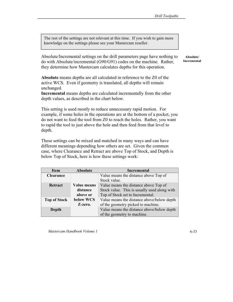
The rest of the settings are not relevant at this time. If you wish to gain more knowledge on the settings please see your Mastercam reseller.
Absolute/Incremental settings on the drill parameters page have nothing to do with Absolute/incremental (G90/G91) codes on the machine. Rather, they determine how Mastercam calculates depths for this operation. Absolute means depths are all calculated in reference to the Z0 of the active WCS. Even if geometry is translated, all depths will remain unchanged. Incremental means depths are calculated incrementally from the other depth values, as described in the chart below. This setting is used mostly to reduce unnecessary rapid motion. For example, if some holes in the operations are at the bottom of a pocket, you do not want to feed the tool from Z0 to reach the holes. Rather, you want to rapid the tool to just above the hole and then feed from that level to depth. These settings can be mixed and matched in many ways and can have different meanings depending how others are set. Given the common case, where Clearance and Retract are above Top of Stock, and Depth is below Top of Stock, here is how these settings work:
Item Absolute Incremental Clearance
Value means
distance above or
below WCS Z-zero.
Value means the distance above Top of Stock value.
Retract Value means the distance above Top of Stock value. This is usually used along with Top of Stock set to Incremental.
Top of Stock Value means the distance above/below depth of the geometry picked to machine.
Depth Value means the distance above/below depth of the geometry to machine.
Chapter 6
Mastercam X6 6-34
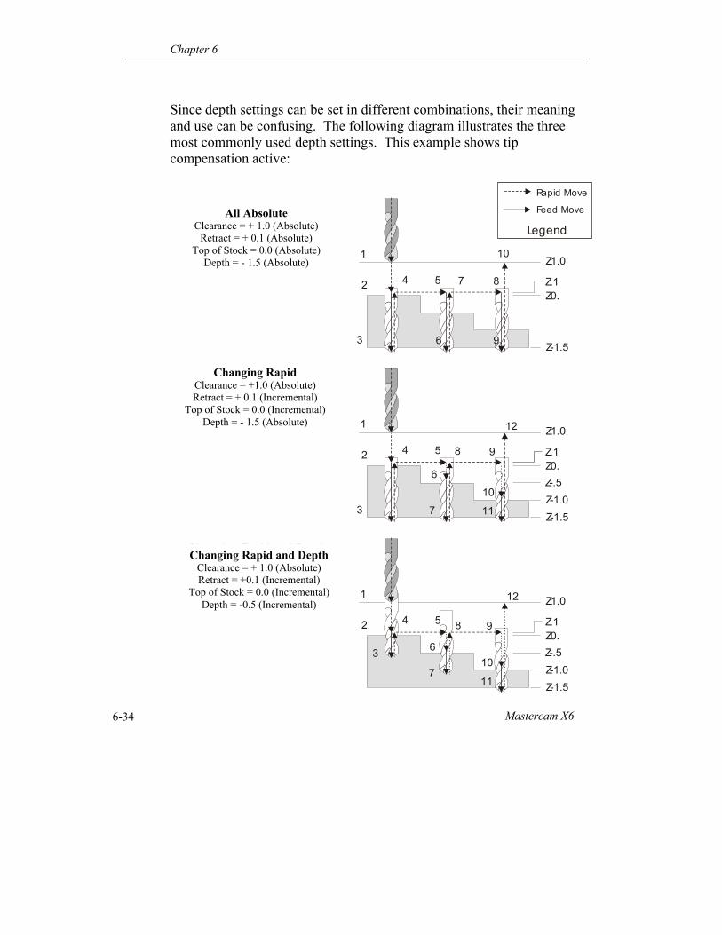
Since depth settings can be set in different combinations, their meaning and use can be confusing. The following diagram illustrates the three most commonly used depth settings. This example shows tip compensation active:
1
2
3
Z1.0
Z.1Z0.
Z-1.5
+ 1.0 (Absolute)+ 0.1 (Absolute) 0.0 (Absolute) -1.5 (Absolute)
Clearance =Retract =
Top of Stock =Depth =
4 5
6
7 8
9
10
All Absolute
1
2
3
Z1.0
Z.1Z0.Z-.5Z-1.0Z-1.5
+ 1.0 (Absolute)+ 0.1 (Incremental) 0.0 (Incremental) -1.5 (Absolute)
Clearance =Retract =
Top of Stock =Depth =
4 5
6
7
8 9
10
Changing Rapid
1
2
3
Z1.0
Z.1Z0.Z-.5Z-1.0Z-1.5
+ 1.0 (Absolute)+ 0.1 (Incremental) 0.0 (Incremental) -0.5 (Incremental)
Clearance =Retract =
Top of Stock =Depth =
4 5
6
7
8 9
10
Changing Rapid and Depth
11
12
11
12
Rapid Move
Feed Move
LegendAll Absolute
Clearance = + 1.0 (Absolute) Retract = + 0.1 (Absolute)
Top of Stock = 0.0 (Absolute) Depth = - 1.5 (Absolute)
Changing Rapid Clearance = +1.0 (Absolute) Retract = + 0.1 (Incremental)
Top of Stock = 0.0 (Incremental) Depth = - 1.5 (Absolute)
Changing Rapid and Depth Clearance = + 1.0 (Absolute) Retract = +0.1 (Incremental)
Top of Stock = 0.0 (Incremental) Depth = -0.5 (Incremental)
Drill Toolpaths
Mastercam Handbook Volume 1 6-35
Drill Cycles
A Drill Cycle, or Canned Cycle, is a command that produces many moves with just a few parameters. For example, a peck drill cycle can command dozens of moves with just a few lines of code. Supported cycles and parameters vary between machines. Some machines do not support drill cycles at all, but most support the cycles listed on the following pages. These examples show a Mastercam drill parameter screen, diagram of tool motion, and sample NC file for the most common drill cycles.
The purpose of the tables and diagrams on the following twelve pages is to help you understand the meaning of data fields in the Mastercam drill parameters dialog boxes. Additional information, such as formulas for calculating tap feeds or dwell times are provided for your convenience. If you do not need to review canned cycles, set parameters the way you want and skip ahead to page 6-51, Operations Manager.
This book assumes you have previously completed a course in CNC operation and basic programming codes or have equivalent experience before using Mastercam. Machine tool languages vary widely from make, manufacturer and even year of production. Even for the same machine, different companies use slightly different programming formats and often have very valid reasons for doing so. Always refer to the machine tool manufacturer’s user manual for information on how to setup, program, and operate your CNC. In any case where the information in this book conflicts with the user manual for your machine, you must use the manufacturer recommendations.
Chapter 6
Mastercam X6 6-36
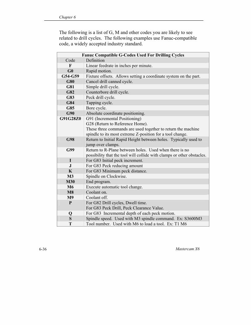
The following is a list of G, M and other codes you are likely to see related to drill cycles. The following examples use Fanuc-compatible code, a widely accepted industry standard.
Fanuc Compatible G-Codes Used For Drilling Cycles Code Definition
F Linear feedrate in inches per minute. G0 Rapid motion.
G54-G59 Fixture offsets. Allows setting a coordinate system on the part. G80 Cancel drill canned cycle. G81 Simple drill cycle. G82 Counterbore drill cycle. G83 Peck drill cycle. G84 Tapping cycle. G85 Bore cycle. G90 Absolute coordinate positioning.
G91G28Z0 G91 (Incremental Positioning) G28 (Return to Reference Home). These three commands are used together to return the machine spindle to its most extreme Z-position for a tool change.
G98 Return to Initial Rapid Height between holes. Typically used to jump over clamps.
G99 Return to R-Plane between holes. Used when there is no possibility that the tool will collide with clamps or other obstacles.
I For G83 Initial peck increment. J For G83 Peck reducing amount K For G83 Minimum peck distance.
M3 Spindle on Clockwise. M30 End program. M6 Execute automatic tool change. M8 Coolant on. M9 Coolant off. P For G82 Drill cycles, Dwell time.
For G83 Peck Drill, Peck Clearance Value. Q For G83 Incremental depth of each peck motion. S Spindle speed. Used with M3 spindle command. Ex: S3600M3 T Tool number. Used with M6 to load a tool. Ex: T1 M6
Drill Toolpaths
Mastercam Handbook Volume 1 6-37
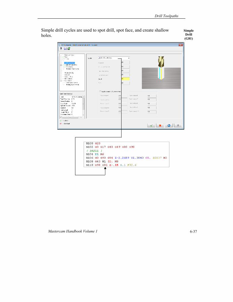
Simple Drill (G81)
Simple drill cycles are used to spot drill, spot face, and create shallow holes.
Chapter 6
Mastercam X6 6-38
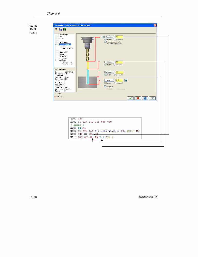
Simple Drill (G81)
Drill Toolpaths
Mastercam Handbook Volume 1 6-39
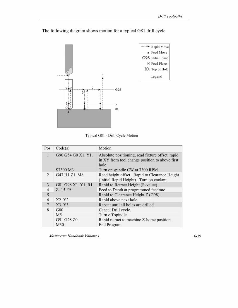
The following diagram shows motion for a typical G81 drill cycle.
Pos. Code(s) Motion
1 G90 G54 G0 X1. Y1. S7300 M3
Absolute positioning, read fixture offset, rapid in XY from tool change position to above first hole. Turn on spindle CW at 7300 RPM.
2 G43 H1 Z1. M8 Read height offset. Rapid to Clearance Height (Initial Rapid Height). Turn on coolant.
3 G81 G98 X1. Y1. R1 Z-.15 F9.
Rapid to Retract Height (R-value). 4 Feed to Depth at programmed feedrate 5 Rapid to Clearance Height Z (G98). 6 X2. Y2. Rapid above next hole. 7 X3. Y3. Repeat until all holes are drilled. 8 G80
M5 G91 G28 Z0. M30
Cancel Drill cycle. Turn off spindle. Rapid retract to machine Z-home position. End Program
Typical G81 - Drill Cycle Motion
Rapid Move
Feed Move
Initial Plane
Feed Plane
Top of Hole
Legend
Chapter 6
Mastercam X6 6-40
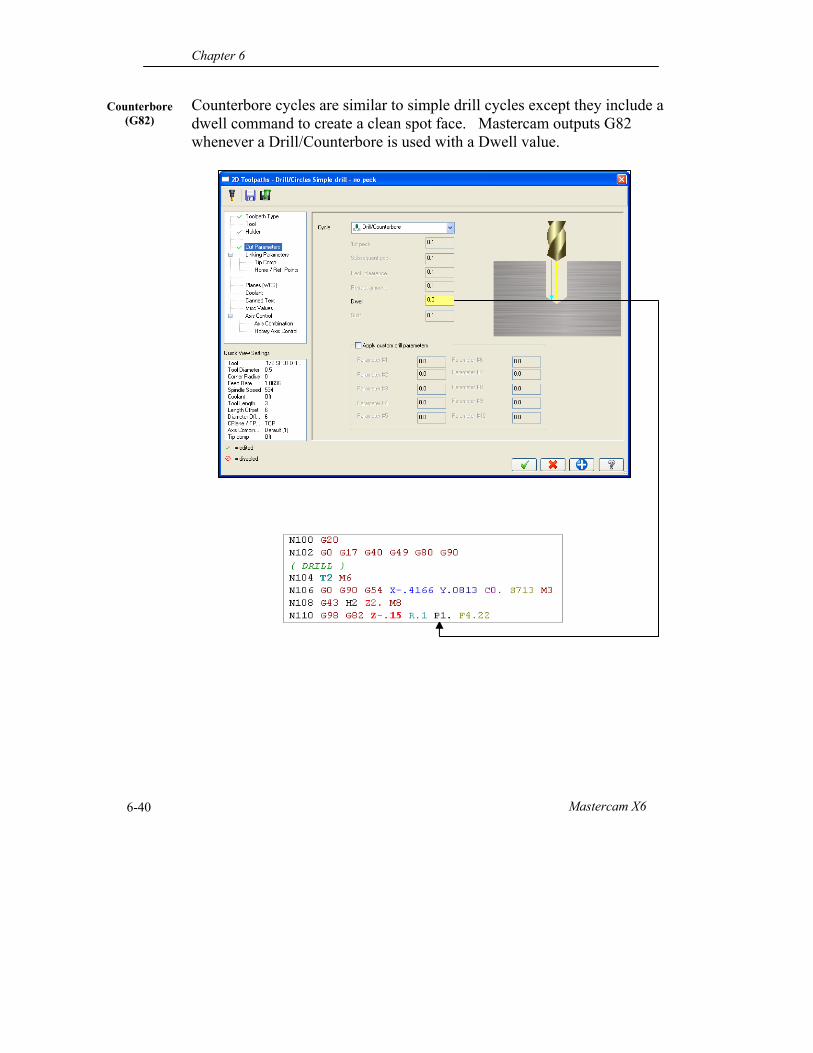
Counterbore cycles are similar to simple drill cycles except they include a dwell command to create a clean spot face. Mastercam outputs G82 whenever a Drill/Counterbore is used with a Dwell value.
Counterbore (G82)
Drill Toolpaths
Mastercam Handbook Volume 1 6-41
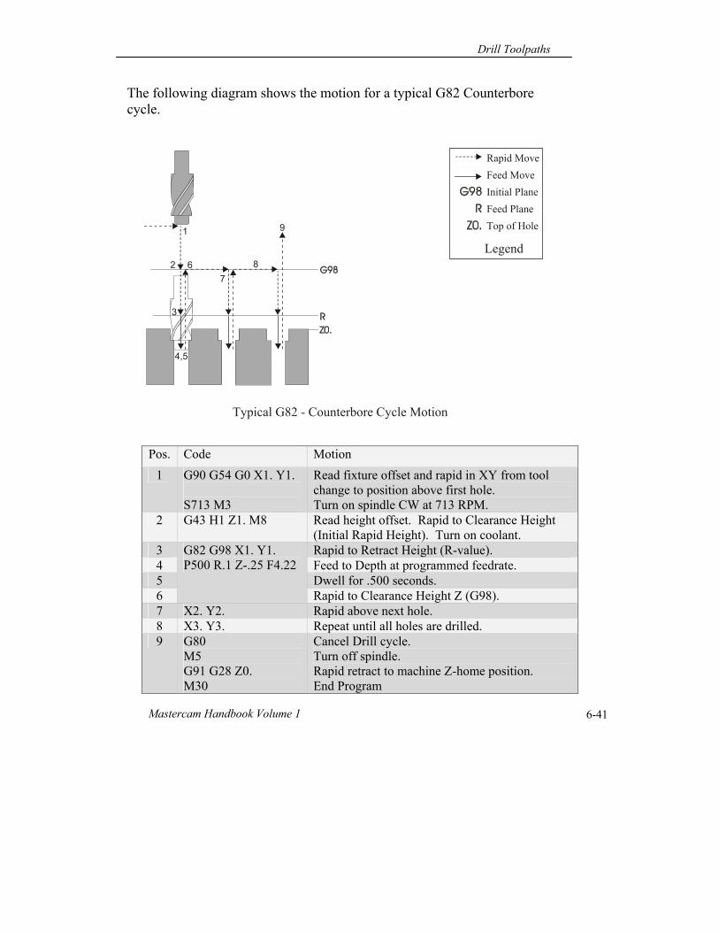
The following diagram shows the motion for a typical G82 Counterbore cycle.
Pos. Code Motion
1 G90 G54 G0 X1. Y1. S713 M3
Read fixture offset and rapid in XY from tool change to position above first hole. Turn on spindle CW at 713 RPM.
2 G43 H1 Z1. M8 Read height offset. Rapid to Clearance Height (Initial Rapid Height). Turn on coolant.
3 G82 G98 X1. Y1. P500 R.1 Z-.25 F4.22
Rapid to Retract Height (R-value). 4 Feed to Depth at programmed feedrate. 5 Dwell for .500 seconds. 6 Rapid to Clearance Height Z (G98). 7 X2. Y2. Rapid above next hole. 8 X3. Y3. Repeat until all holes are drilled. 9 G80
M5 G91 G28 Z0. M30
Cancel Drill cycle. Turn off spindle. Rapid retract to machine Z-home position. End Program
Typical G82 - Counterbore Cycle Motion
1
2 67
8
9
3
4,5
Rapid Move
Feed Move
Initial Plane
Feed Plane
Top of Hole
Legend
Chapter 6
Mastercam X6 6-42
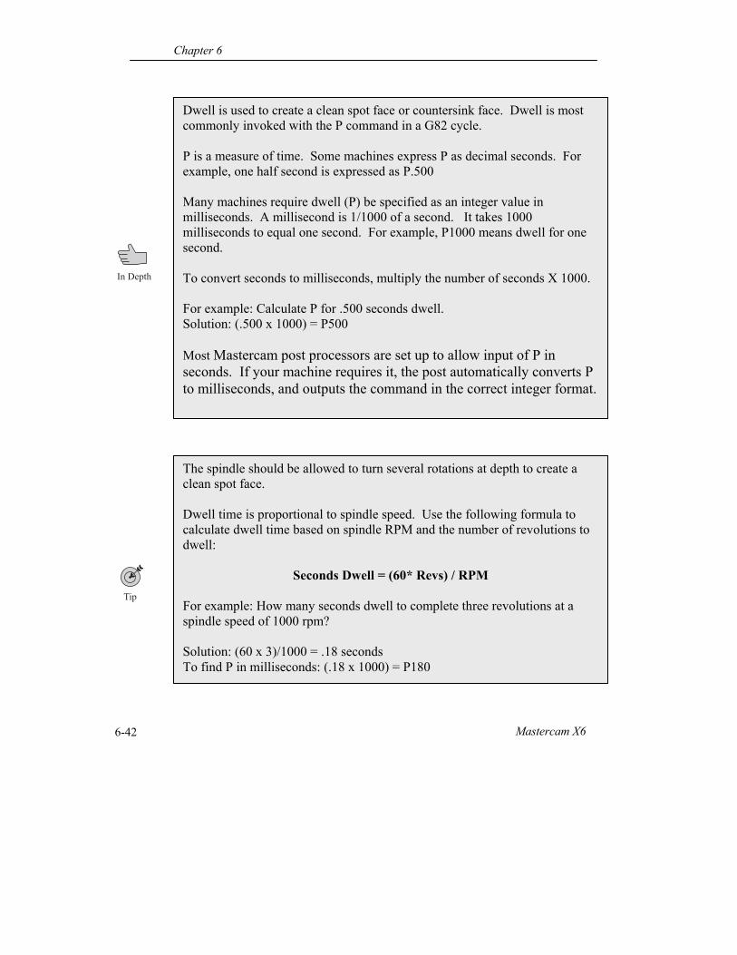
Dwell is used to create a clean spot face or countersink face. Dwell is most commonly invoked with the P command in a G82 cycle. P is a measure of time. Some machines express P as decimal seconds. For example, one half second is expressed as P.500 Many machines require dwell (P) be specified as an integer value in milliseconds. A millisecond is 1/1000 of a second. It takes 1000 milliseconds to equal one second. For example, P1000 means dwell for one second. To convert seconds to milliseconds, multiply the number of seconds X 1000. For example: Calculate P for .500 seconds dwell. Solution: (.500 x 1000) = P500 Most Mastercam post processors are set up to allow input of P in seconds. If your machine requires it, the post automatically converts P to milliseconds, and outputs the command in the correct integer format.
The spindle should be allowed to turn several rotations at depth to create a clean spot face. Dwell time is proportional to spindle speed. Use the following formula to calculate dwell time based on spindle RPM and the number of revolutions to dwell:
Seconds Dwell = (60* Revs) / RPM For example: How many seconds dwell to complete three revolutions at a spindle speed of 1000 rpm? Solution: (60 x 3)/1000 = .18 seconds To find P in milliseconds: (.18 x 1000) = P180
Drill Toolpaths
Mastercam Handbook Volume 1 6-43
Peck Drill (G83)
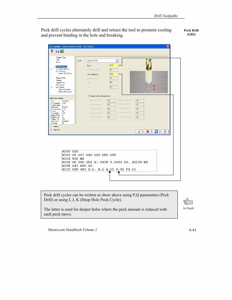
Peck drill cycles alternately drill and retract the tool to promote cooling and prevent binding in the hole and breaking.
Peck drill cycles can be written as show above using P,Q parameters (Peck Drill) or using I, J, K (Deep Hole Peck Cycle). The latter is used for deeper holes where the peck amount is reduced with each peck move.
Chapter 6
Mastercam X6 6-44
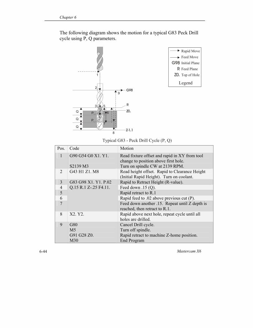
The following diagram shows the motion for a typical G83 Peck Drill cycle using P, Q parameters.
Pos. Code Motion
1 G90 G54 G0 X1. Y1. S2139 M3
Read fixture offset and rapid in XY from tool change to position above first hole. Turn on spindle CW at 2139 RPM.
2 G43 H1 Z1. M8 Read height offset. Rapid to Clearance Height (Initial Rapid Height). Turn on coolant.
3 G83 G98 X1. Y1. P.02 Q.15 R.1 Z-.25 F4.11.
Rapid to Retract Height (R-value). 4 Feed down .15 (Q). 5 Rapid retract to R.1 6 Rapid feed to .02 above previous cut (P). 7 Feed down another .15. Repeat until Z depth is
reached, then retract to R.1. 8 X2. Y2. Rapid above next hole, repeat cycle until all
holes are drilled. 9 G80
M5 G91 G28 Z0. M30
Cancel Drill cycle. Turn off spindle. Rapid retract to machine Z-home position. End Program
1
2
3Q
Typical G83 - Peck Drill Cycle (P, Q)
4
5
P 6
7
8
Rapid Move
Feed Move
Initial Plane
Feed Plane
Top of Hole
Legend
Q
Q
P
9
Drill Toolpaths
Mastercam Handbook Volume 1 6-45
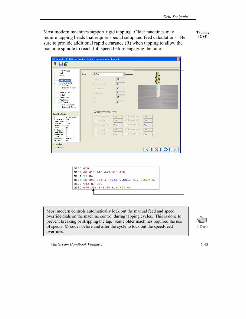
Tapping (G84)
Most modern machines support rigid tapping. Older machines may require tapping heads that require special setup and feed calculations. Be sure to provide additional rapid clearance (R) when tapping to allow the machine spindle to reach full speed before engaging the hole.
Most modern controls automatically lock out the manual feed and speed override dials on the machine control during tapping cycles. This is done to prevent breaking or stripping the tap. Some older machines required the use of special M-codes before and after the cycle to lock out the speed/feed overrides.
Chapter 6
Mastercam X6 6-46
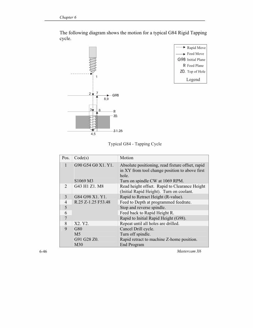
The following diagram shows the motion for a typical G84 Rigid Tapping cycle.
Pos. Code(s) Motion
1 G90 G54 G0 X1. Y1. S1069 M3
Absolute positioning, read fixture offset, rapid in XY from tool change position to above first hole. Turn on spindle CW at 1069 RPM.
2 G43 H1 Z1. M8 Read height offset. Rapid to Clearance Height (Initial Rapid Height). Turn on coolant.
3 G84 G98 X1. Y1. R.25 Z-1.25 F53.48
Rapid to Retract Height (R-value). 4 Feed to Depth at programmed feedrate. 5 Stop and reverse spindle. 6 Feed back to Rapid Height R. 7 Rapid to Initial Rapid Height (G98). 8 X2. Y2. Repeat until all holes are drilled. 9 G80
M5 G91 G28 Z0. M30
Cancel Drill cycle. Turn off spindle. Rapid retract to machine Z-home position. End Program
Typical G84 - Tapping Cycle
Rapid Move
1
2
3
4,5
7
6
8,9
Feed Move
Initial Plane
Feed Plane
Top of Hole
Legend
Drill Toolpaths
Mastercam Handbook Volume 1 6-47
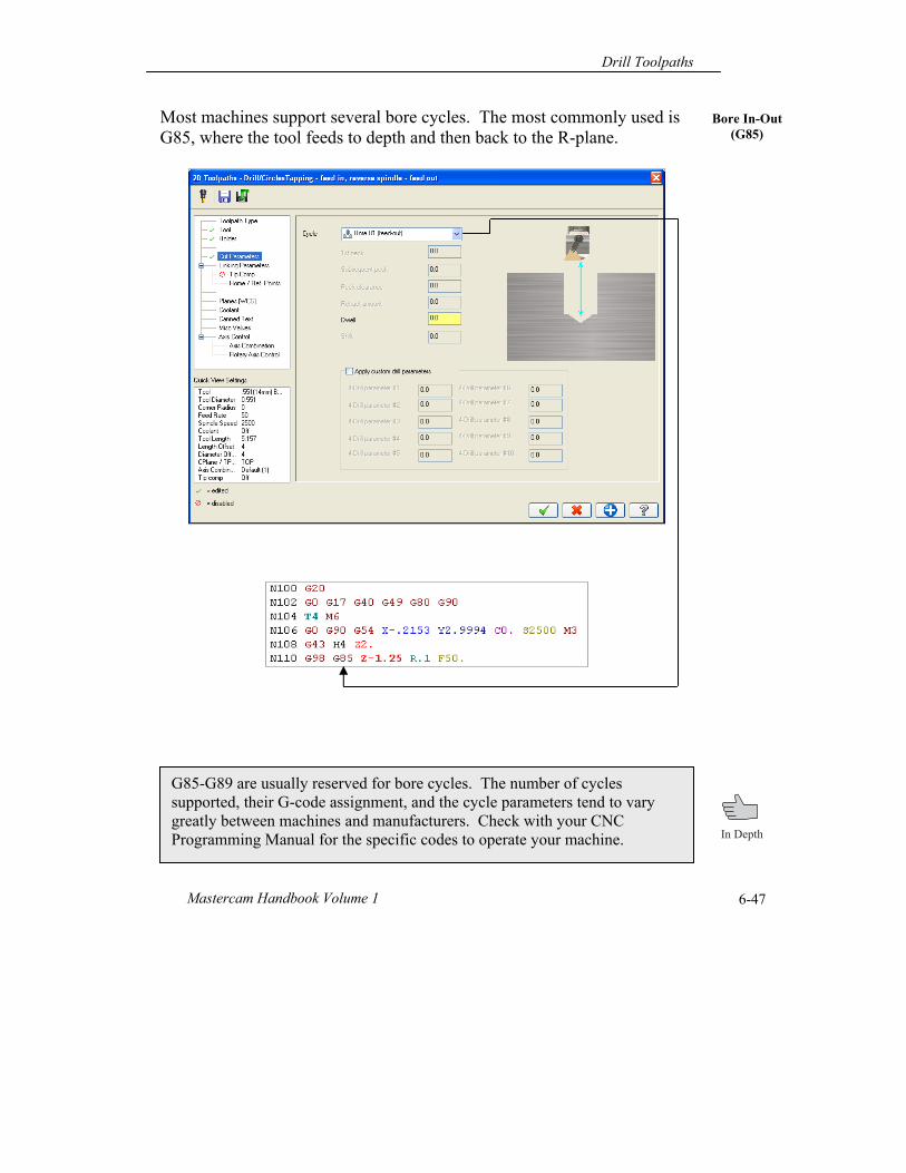
Bore In-Out (G85)
Most machines support several bore cycles. The most commonly used is G85, where the tool feeds to depth and then back to the R-plane.
G85-G89 are usually reserved for bore cycles. The number of cycles supported, their G-code assignment, and the cycle parameters tend to vary greatly between machines and manufacturers. Check with your CNC Programming Manual for the specific codes to operate your machine.
Chapter 6
Mastercam X6 6-48
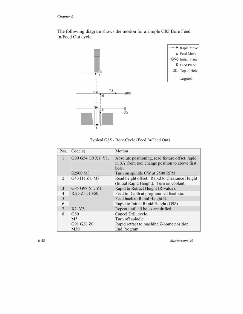
The following diagram shows the motion for a simple G85 Bore Feed In/Feed Out cycle.
Pos. Code(s) Motion
1 G90 G54 G0 X1. Y1. S2500 M3
Absolute positioning, read fixture offset, rapid in XY from tool change position to above first hole. Turn on spindle CW at 2500 RPM.
2 G43 H1 Z1. M8 Read height offset. Rapid to Clearance Height (Initial Rapid Height). Turn on coolant.
3 G85 G98 X1. Y1. R.25 Z-1.1 F50
Rapid to Retract Height (R-value). 4 Feed to Depth at programmed feedrate. 5 Feed back to Rapid Height R. 6 Rapid to Initial Rapid Height (G98). 7 X2. Y2. Repeat until all holes are drilled. 8 G80
M5 G91 G28 Z0. M30
Cancel Drill cycle. Turn off spindle. Rapid retract to machine Z-home position. End Program
Typical G85 - Bore Cycle (Feed In/Feed Out)
1
2
3
4
6
5
7,8
Rapid Move
Feed Move
Initial Plane
Feed Plane
Top of Hole
Legend
Drill Toolpaths
Mastercam Handbook Volume 1 6-49
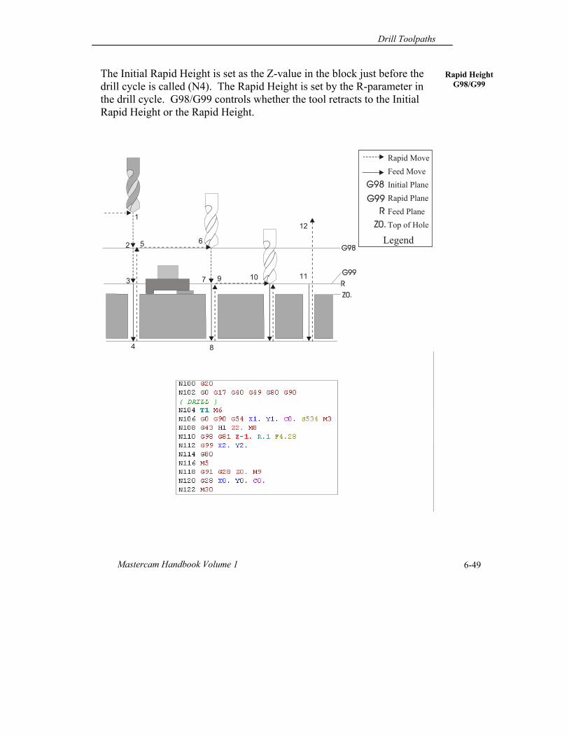
Rapid Height G98/G99
The Initial Rapid Height is set as the Z-value in the block just before the drill cycle is called (N4). The Rapid Height is set by the R-parameter in the drill cycle. G98/G99 controls whether the tool retracts to the Initial Rapid Height or the Rapid Height.
12
9
10 11
Sample NC Program
N4 G43 H1 Z1. M08N5 G81 X1. Y1. R.1 Z-1.1 F17. N6 X2. Y2.N7 X3. Y3.N8 X4. Y4.N9 G80
G98G99
N1 T1 M6N2 G90 G54 G0 X1. Y1.N3 S7300 M3
N10 M9N11 M5 N11 G91 G28 Z0.N12 M30
1
2 5 6
7
8
3
4
Rapid Move
Feed Move
Initial Plane
Rapid Plane
Feed Plane
Top of Hole
Legend
Chapter 6
Mastercam X6 6-50
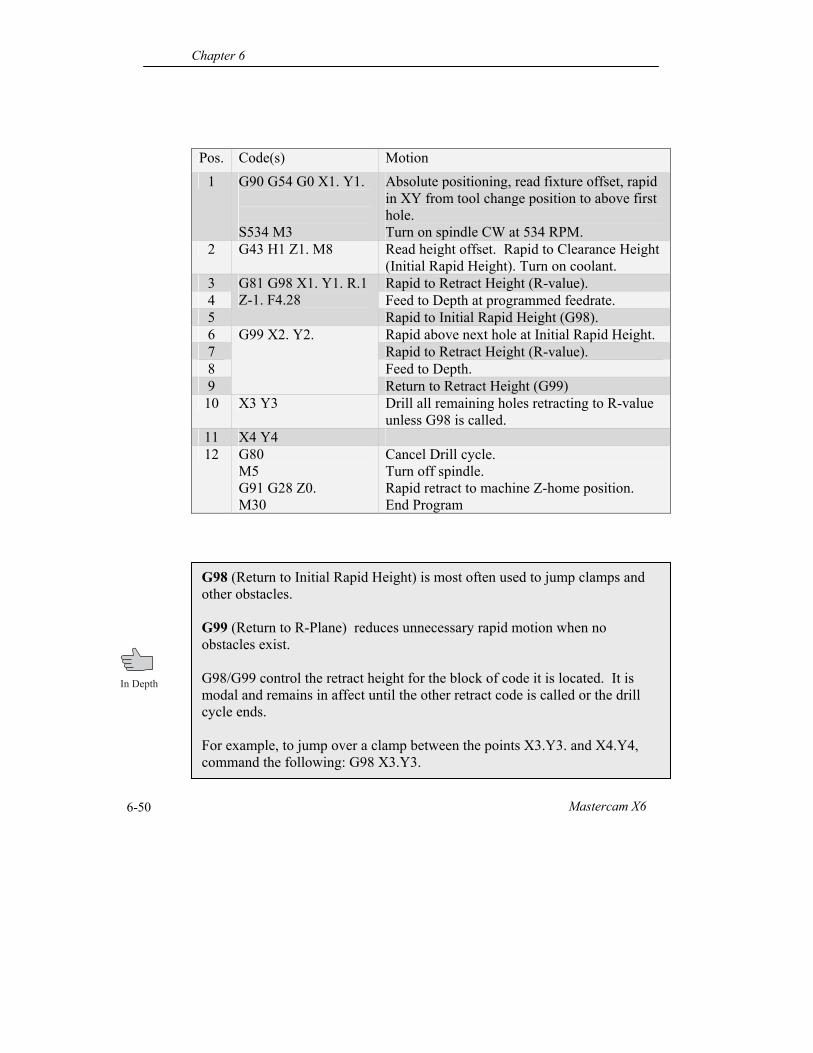
Pos. Code(s) Motion
1 G90 G54 G0 X1. Y1. S534 M3
Absolute positioning, read fixture offset, rapid in XY from tool change position to above first hole. Turn on spindle CW at 534 RPM.
2 G43 H1 Z1. M8 Read height offset. Rapid to Clearance Height (Initial Rapid Height). Turn on coolant.
3 G81 G98 X1. Y1. R.1 Z-1. F4.28
Rapid to Retract Height (R-value). 4 Feed to Depth at programmed feedrate. 5 Rapid to Initial Rapid Height (G98). 6 G99 X2. Y2. Rapid above next hole at Initial Rapid Height. 7 Rapid to Retract Height (R-value). 8 Feed to Depth. 9 Return to Retract Height (G99) 10 X3 Y3 Drill all remaining holes retracting to R-value
unless G98 is called. 11 X4 Y4 12 G80
M5 G91 G28 Z0. M30
Cancel Drill cycle. Turn off spindle. Rapid retract to machine Z-home position. End Program
G98 (Return to Initial Rapid Height) is most often used to jump clamps and other obstacles. G99 (Return to R-Plane) reduces unnecessary rapid motion when no obstacles exist. G98/G99 control the retract height for the block of code it is located. It is modal and remains in affect until the other retract code is called or the drill cycle ends. For example, to jump over a clamp between the points X3.Y3. and X4.Y4, command the following: G98 X3.Y3.
Drill Toolpaths
Mastercam Handbook Volume 1 6-51
Operations Manager
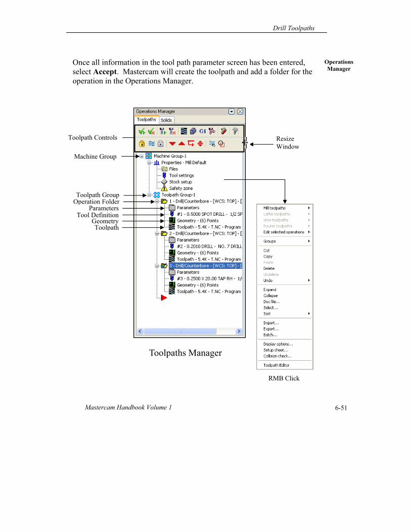
Once all information in the tool path parameter screen has been entered, select Accept. Mastercam will create the toolpath and add a folder for the operation in the Operations Manager.
Toolpath
Toolpaths Manager
Resize Window
RMB Click
Geometry Tool Definition
Parameters
Toolpath Group Operation Folder
Machine Group
Toolpath Controls
Chapter 6
Mastercam X6 6-52
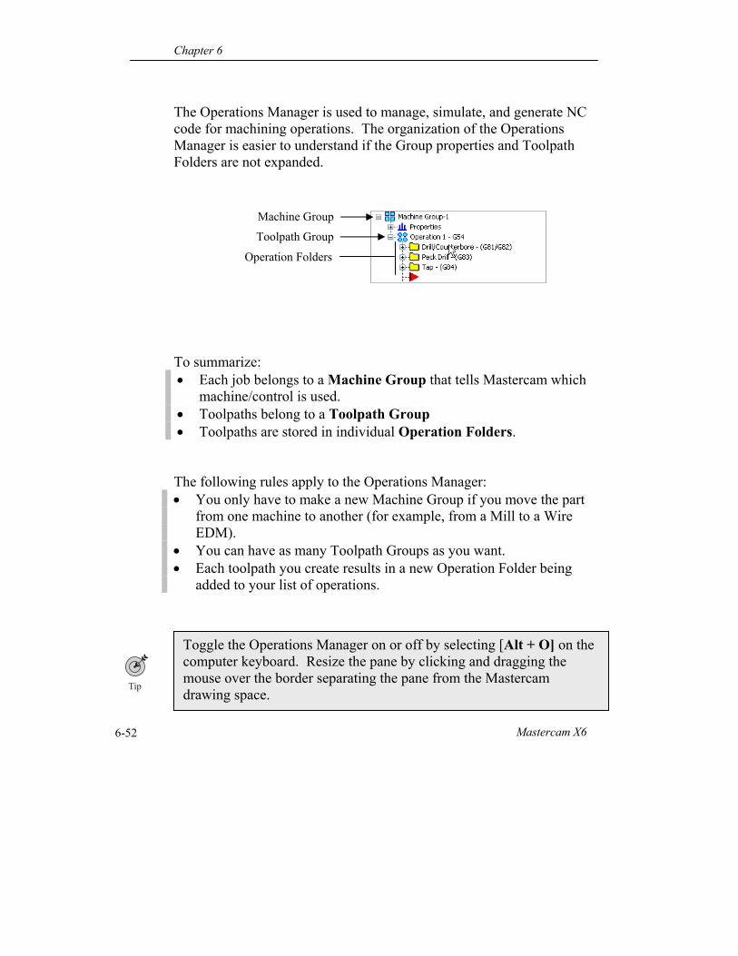
The Operations Manager is used to manage, simulate, and generate NC code for machining operations. The organization of the Operations Manager is easier to understand if the Group properties and Toolpath Folders are not expanded. To summarize: Each job belongs to a Machine Group that tells Mastercam which
machine/control is used. Toolpaths belong to a Toolpath Group Toolpaths are stored in individual Operation Folders. The following rules apply to the Operations Manager: You only have to make a new Machine Group if you move the part
from one machine to another (for example, from a Mill to a Wire EDM).
You can have as many Toolpath Groups as you want. Each toolpath you create results in a new Operation Folder being
added to your list of operations.
Toggle the Operations Manager on or off by selecting [Alt + O] on the computer keyboard. Resize the pane by clicking and dragging the mouse over the border separating the pane from the Mastercam drawing space.
Machine Group
Toolpath Group
Operation Folders
Drill Toolpaths
Mastercam Handbook Volume 1 6-53
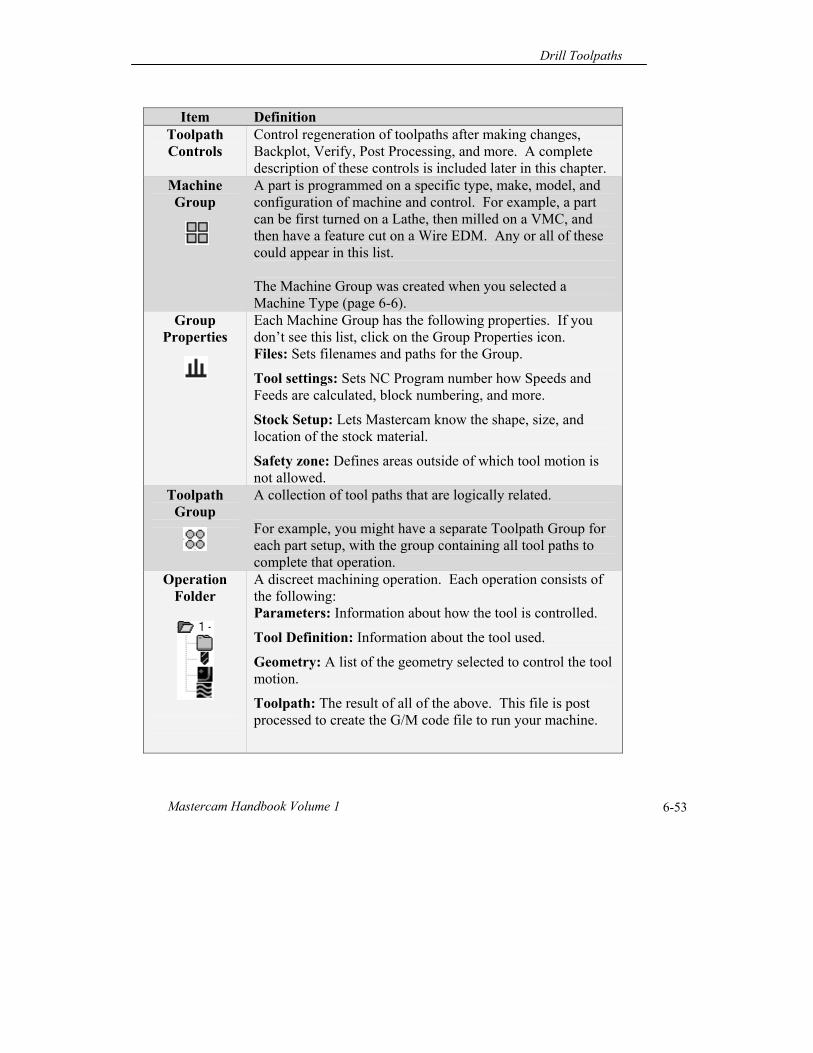
Item Definition Toolpath Controls
Control regeneration of toolpaths after making changes, Backplot, Verify, Post Processing, and more. A complete description of these controls is included later in this chapter.
Machine Group
A part is programmed on a specific type, make, model, and configuration of machine and control. For example, a part can be first turned on a Lathe, then milled on a VMC, and then have a feature cut on a Wire EDM. Any or all of these could appear in this list. The Machine Group was created when you selected a Machine Type (page 6-6).
Group Properties
Each Machine Group has the following properties. If you don’t see this list, click on the Group Properties icon. Files: Sets filenames and paths for the Group.
Tool settings: Sets NC Program number how Speeds and Feeds are calculated, block numbering, and more.
Stock Setup: Lets Mastercam know the shape, size, and location of the stock material.
Safety zone: Defines areas outside of which tool motion is not allowed.
Toolpath Group
A collection of tool paths that are logically related. For example, you might have a separate Toolpath Group for each part setup, with the group containing all tool paths to complete that operation.
Operation Folder
A discreet machining operation. Each operation consists of the following: Parameters: Information about how the tool is controlled.
Tool Definition: Information about the tool used.
Geometry: A list of the geometry selected to control the tool motion.
Toolpath: The result of all of the above. This file is post processed to create the G/M code file to run your machine.
Chapter 6
Mastercam X6 6-54
Toolpath Controls
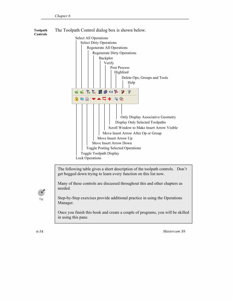
The Toolpath Control dialog box is shown below.
The following table gives a short description of the toolpath controls. Don’t get bogged down trying to learn every function on this list now. Many of these controls are discussed throughout this and other chapters as needed. Step-by-Step exercises provide additional practice in using the Operations Manager. Once you finish this book and create a couple of programs, you will be skilled in using this pane.
Select All Operations Select Dirty Operations
Regenerate All Operations Regenerate Dirty Operations
Backplot Verify
Post Process Highfeed
Delete Ops, Groups and Tools Help
Lock Operations Toggle Toolpath Display
Toggle Posting Selected Operations Move Insert Arrow Down
Move Insert Arrow Up Move Insert Arrow After Op or Group
Scroll Window to Make Insert Arrow Visible
Display Only Selected Toolpaths Only Display Associative Geometry
Drill Toolpaths
Mastercam Handbook Volume 1 6-55
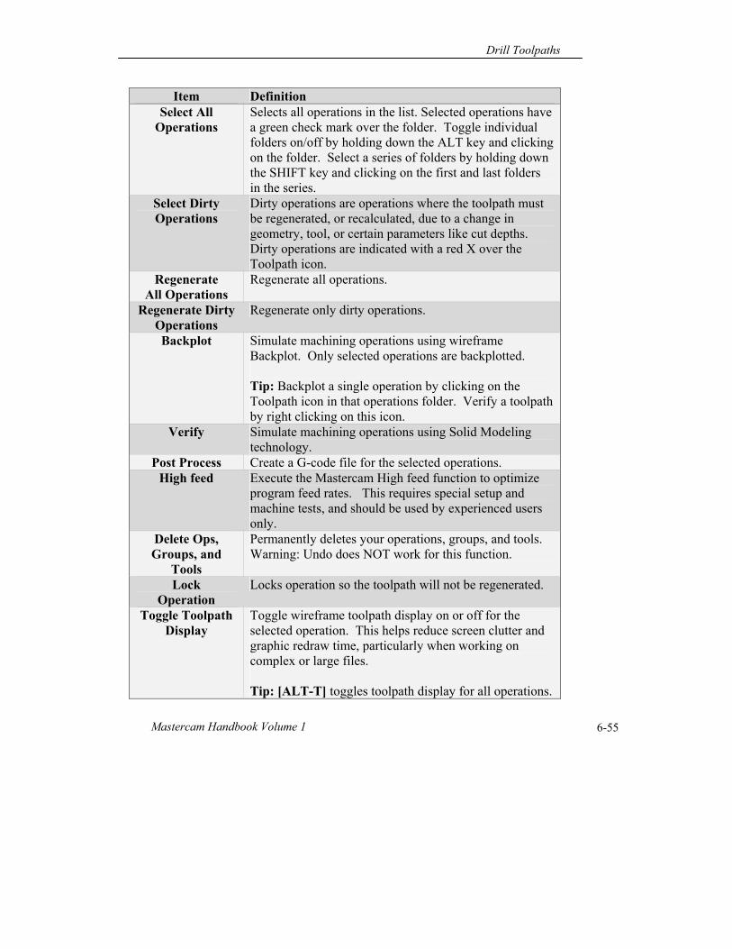
Item Definition Select All
Operations Selects all operations in the list. Selected operations have a green check mark over the folder. Toggle individual folders on/off by holding down the ALT key and clicking on the folder. Select a series of folders by holding down the SHIFT key and clicking on the first and last folders in the series.
Select Dirty Operations
Dirty operations are operations where the toolpath must be regenerated, or recalculated, due to a change in geometry, tool, or certain parameters like cut depths. Dirty operations are indicated with a red X over the Toolpath icon.
Regenerate All Operations
Regenerate all operations.
Regenerate Dirty Operations
Regenerate only dirty operations.
Backplot Simulate machining operations using wireframe Backplot. Only selected operations are backplotted. Tip: Backplot a single operation by clicking on the Toolpath icon in that operations folder. Verify a toolpath by right clicking on this icon.
Verify Simulate machining operations using Solid Modeling technology.
Post Process Create a G-code file for the selected operations. High feed Execute the Mastercam High feed function to optimize
program feed rates. This requires special setup and machine tests, and should be used by experienced users only.
Delete Ops, Groups, and
Tools
Permanently deletes your operations, groups, and tools. Warning: Undo does NOT work for this function.
Lock Operation
Locks operation so the toolpath will not be regenerated.
Toggle Toolpath Display
Toggle wireframe toolpath display on or off for the selected operation. This helps reduce screen clutter and graphic redraw time, particularly when working on complex or large files. Tip: [ALT-T] toggles toolpath display for all operations.
Chapter 6
Mastercam X6 6-56
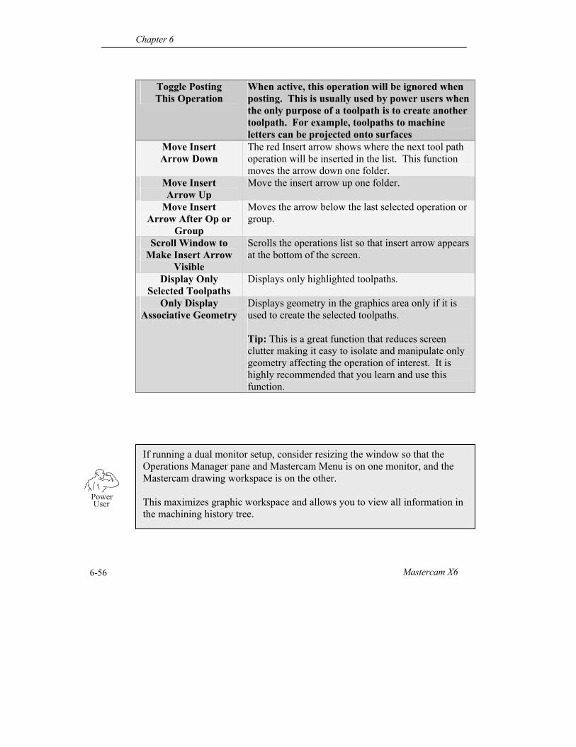
Toggle Posting This Operation
When active, this operation will be ignored when posting. This is usually used by power users when the only purpose of a toolpath is to create another toolpath. For example, toolpaths to machine letters can be projected onto surfaces
Move Insert Arrow Down
The red Insert arrow shows where the next tool path operation will be inserted in the list. This function moves the arrow down one folder.
Move Insert Arrow Up
Move the insert arrow up one folder.
Move Insert Arrow After Op or
Group
Moves the arrow below the last selected operation or group.
Scroll Window to Make Insert Arrow
Visible
Scrolls the operations list so that insert arrow appears at the bottom of the screen.
Display Only Selected Toolpaths
Displays only highlighted toolpaths.
Only Display Associative Geometry
Displays geometry in the graphics area only if it is used to create the selected toolpaths. Tip: This is a great function that reduces screen clutter making it easy to isolate and manipulate only geometry affecting the operation of interest. It is highly recommended that you learn and use this function.
If running a dual monitor setup, consider resizing the window so that the Operations Manager pane and Mastercam Menu is on one monitor, and the Mastercam drawing workspace is on the other. This maximizes graphic workspace and allows you to view all information in the machining history tree.
PowerUser
Drill Toolpaths
Mastercam Handbook Volume 1 6-57
Changing Toolpaths
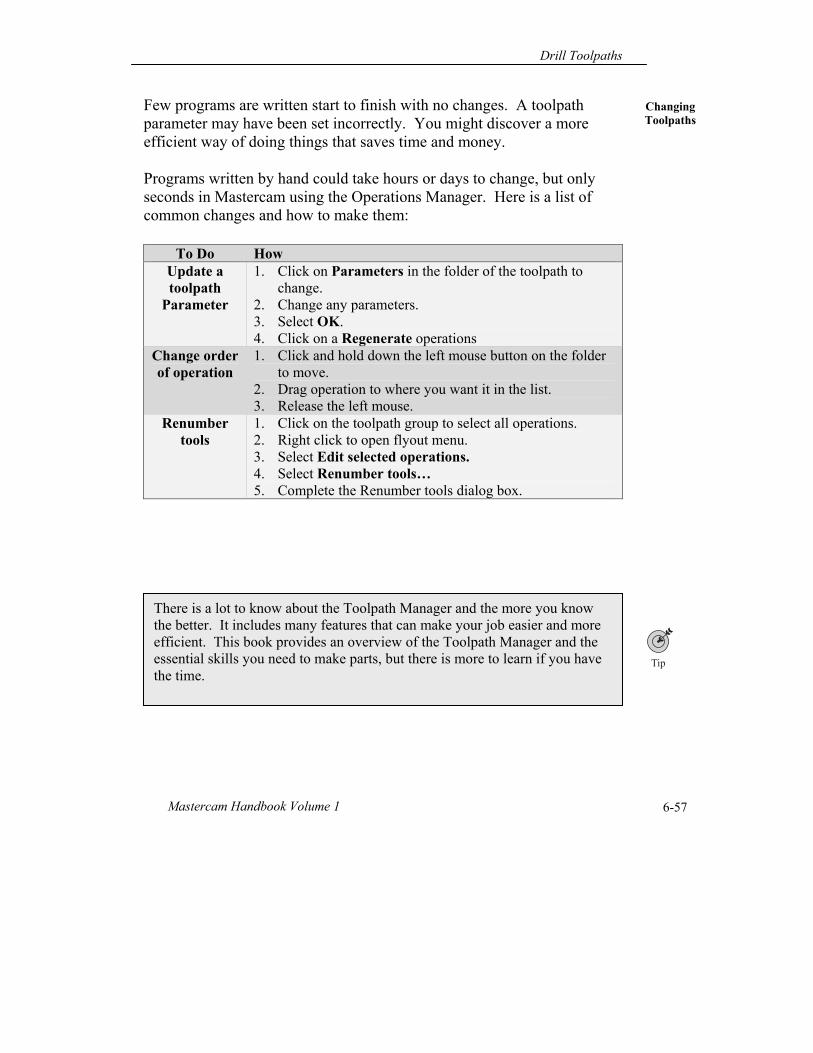
Few programs are written start to finish with no changes. A toolpath parameter may have been set incorrectly. You might discover a more efficient way of doing things that saves time and money. Programs written by hand could take hours or days to change, but only seconds in Mastercam using the Operations Manager. Here is a list of common changes and how to make them:
To Do How Update a toolpath
Parameter
1. Click on Parameters in the folder of the toolpath to change.
2. Change any parameters. 3. Select OK. 4. Click on a Regenerate operations
Change order of operation
1. Click and hold down the left mouse button on the folder to move.
2. Drag operation to where you want it in the list. 3. Release the left mouse.
Renumber tools
1. Click on the toolpath group to select all operations. 2. Right click to open flyout menu. 3. Select Edit selected operations. 4. Select Renumber tools… 5. Complete the Renumber tools dialog box.
There is a lot to know about the Toolpath Manager and the more you know the better. It includes many features that can make your job easier and more efficient. This book provides an overview of the Toolpath Manager and the essential skills you need to make parts, but there is more to learn if you have the time.
Chapter 6
Mastercam X6 6-58
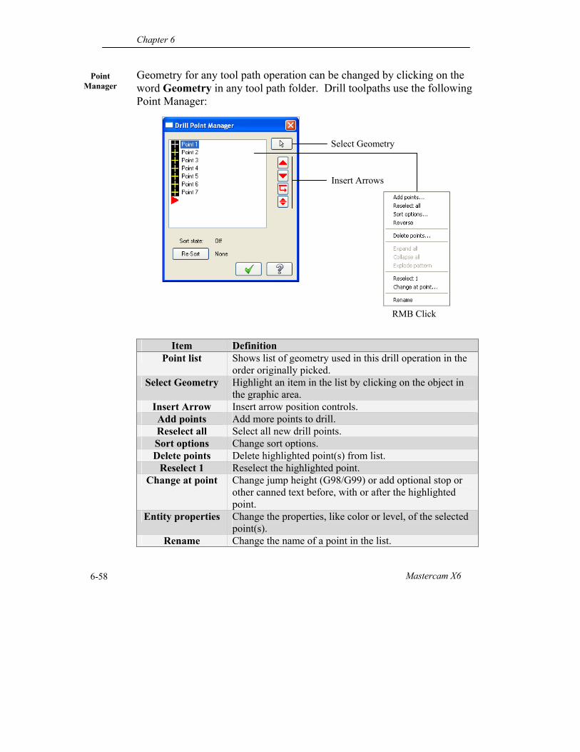
Point Manager
Geometry for any tool path operation can be changed by clicking on the word Geometry in any tool path folder. Drill toolpaths use the following Point Manager:
Item Definition Point list Shows list of geometry used in this drill operation in the
order originally picked. Select Geometry Highlight an item in the list by clicking on the object in
the graphic area. Insert Arrow Insert arrow position controls. Add points Add more points to drill. Reselect all Select all new drill points. Sort options Change sort options. Delete points Delete highlighted point(s) from list.
Reselect 1 Reselect the highlighted point. Change at point Change jump height (G98/G99) or add optional stop or
other canned text before, with or after the highlighted point.
Entity properties Change the properties, like color or level, of the selected point(s).
Rename Change the name of a point in the list.
Select Geometry
Insert Arrows
RMB Click
Drill Toolpaths
Mastercam Handbook Volume 1 6-59
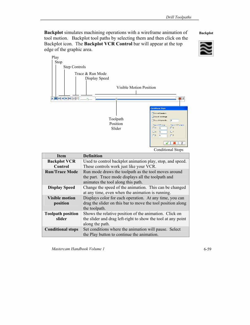
Backplot Backplot simulates machining operations with a wireframe animation of tool motion. Backplot tool paths by selecting them and then click on the Backplot icon. The Backplot VCR Control bar will appear at the top edge of the graphic area.
Item Definition Backplot VCR
Control Used to control backplot animation play, stop, and speed. These controls work just like your VCR.
Run/Trace Mode Run mode draws the toolpath as the tool moves around the part. Trace mode displays all the toolpath and animates the tool along this path.
Display Speed Change the speed of the animation. This can be changed at any time, even when the animation is running.
Visible motion position
Displays color for each operation. At any time, you can drag the slider on this bar to move the tool position along the toolpath.
Toolpath position slider
Shows the relative position of the animation. Click on the slider and drag left-right to show the tool at any point along the path.
Conditional stops Set conditions where the animation will pause. Select the Play button to continue the animation.
Play Stop
Step Controls
Trace & Run Mode Display Speed
Visible Motion Position
Toolpath Position Slider
Conditional Stops
Chapter 6
Mastercam X6 6-60
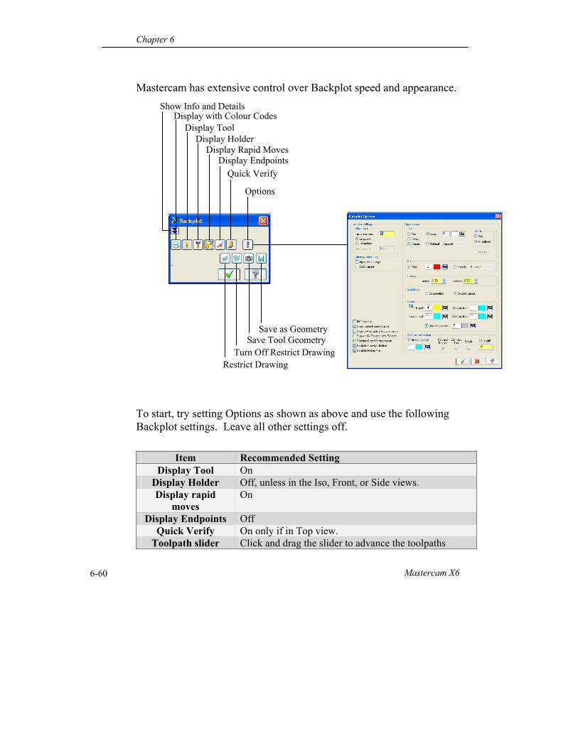
Mastercam has extensive control over Backplot speed and appearance. To start, try setting Options as shown as above and use the following Backplot settings. Leave all other settings off.
Item Recommended Setting Display Tool On
Display Holder Off, unless in the Iso, Front, or Side views. Display rapid
moves On
Display Endpoints Off Quick Verify On only if in Top view.
Toolpath slider Click and drag the slider to advance the toolpaths
Show Info and Details Display with Colour Codes
Display Tool Display Holder
Display Rapid Moves Display Endpoints
Quick Verify
Options
Restrict Drawing Turn Off Restrict Drawing
Save Tool Geometry Save as Geometry
Drill Toolpaths
Mastercam Handbook Volume 1 6-61
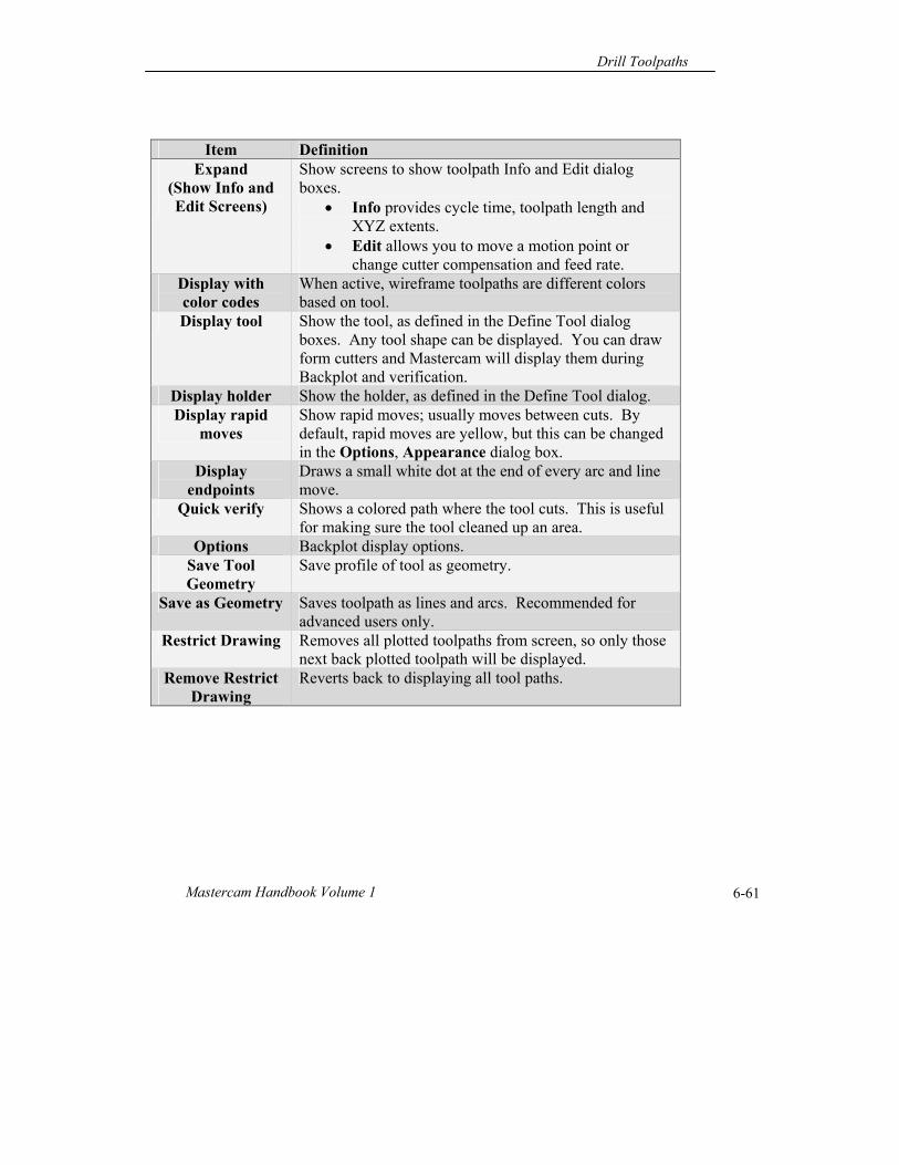
Item Definition Expand
(Show Info and Edit Screens)
Show screens to show toolpath Info and Edit dialog boxes.
Info provides cycle time, toolpath length and XYZ extents.
Edit allows you to move a motion point or change cutter compensation and feed rate.
Display with color codes
When active, wireframe toolpaths are different colors based on tool.
Display tool Show the tool, as defined in the Define Tool dialog boxes. Any tool shape can be displayed. You can draw form cutters and Mastercam will display them during Backplot and verification.
Display holder Show the holder, as defined in the Define Tool dialog. Display rapid
moves Show rapid moves; usually moves between cuts. By default, rapid moves are yellow, but this can be changed in the Options, Appearance dialog box.
Display endpoints
Draws a small white dot at the end of every arc and line move.
Quick verify Shows a colored path where the tool cuts. This is useful for making sure the tool cleaned up an area.
Options Backplot display options. Save Tool Geometry
Save profile of tool as geometry.
Save as Geometry Saves toolpath as lines and arcs. Recommended for advanced users only.
Restrict Drawing Removes all plotted toolpaths from screen, so only those next back plotted toolpath will be displayed.
Remove Restrict Drawing
Reverts back to displaying all tool paths.
Chapter 6
Mastercam X6 6-62
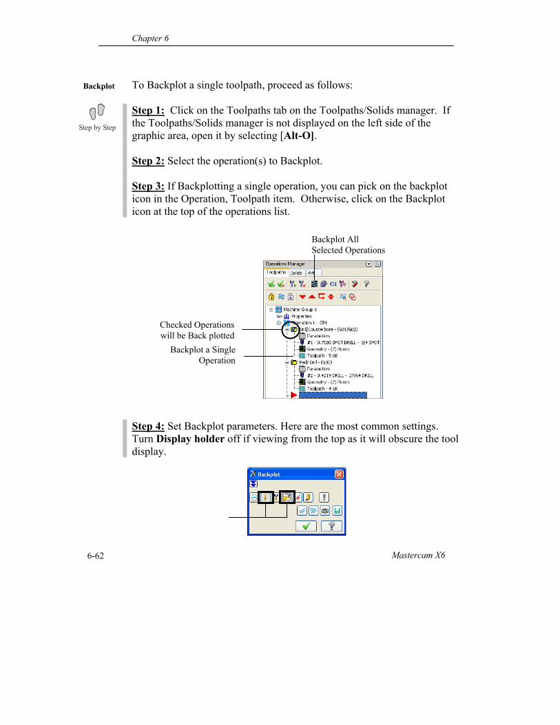
Backplot
To Backplot a single toolpath, proceed as follows: Step 1: Click on the Toolpaths tab on the Toolpaths/Solids manager. If the Toolpaths/Solids manager is not displayed on the left side of the graphic area, open it by selecting [Alt-O]. Step 2: Select the operation(s) to Backplot. Step 3: If Backplotting a single operation, you can pick on the backplot icon in the Operation, Toolpath item. Otherwise, click on the Backplot icon at the top of the operations list. Step 4: Set Backplot parameters. Here are the most common settings. Turn Display holder off if viewing from the top as it will obscure the tool display.
Backplot All Selected Operations
Checked Operations will be Back plotted
Backplot a Single Operation
Drill Toolpaths
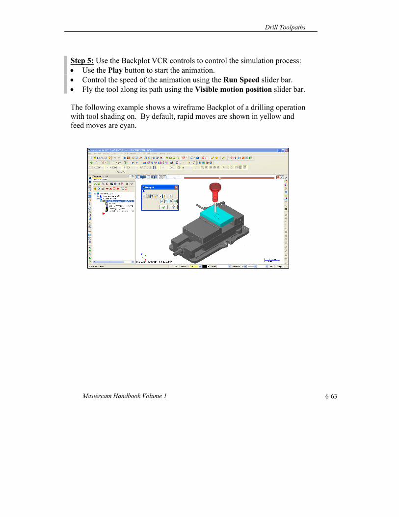
Mastercam Handbook Volume 1 6-63
Step 5: Use the Backplot VCR controls to control the simulation process: Use the Play button to start the animation. Control the speed of the animation using the Run Speed slider bar. Fly the tool along its path using the Visible motion position slider bar. The following example shows a wireframe Backplot of a drilling operation with tool shading on. By default, rapid moves are shown in yellow and feed moves are cyan.
Chapter 6
Mastercam X6 6-64
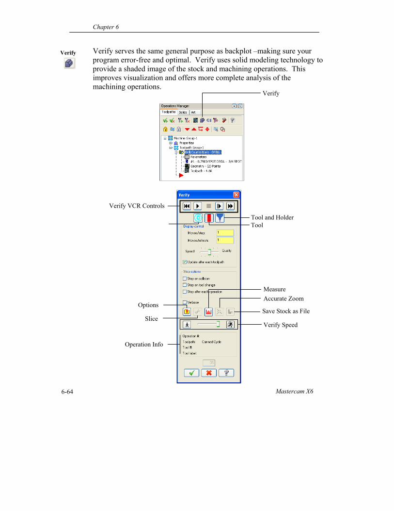
Verify Verify serves the same general purpose as backplot –making sure your program error-free and optimal. Verify uses solid modeling technology to provide a shaded image of the stock and machining operations. This improves visualization and offers more complete analysis of the machining operations.
Verify VCR Controls
Verify
Operation Info
Verify Speed
Save Stock as File
Accurate Zoom
Measure
Slice
Options
Tool and Holder Tool
Drill Toolpaths
Mastercam Handbook Volume 1 6-65
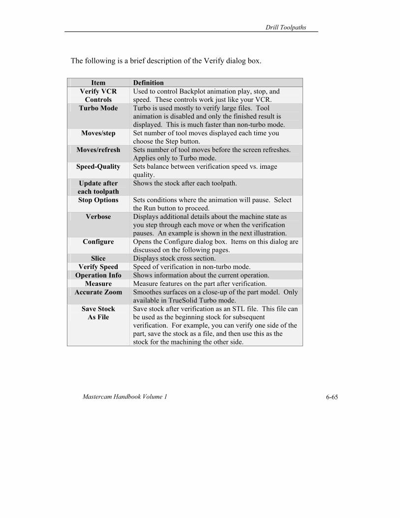
The following is a brief description of the Verify dialog box.
Item Definition Verify VCR
Controls Used to control Backplot animation play, stop, and speed. These controls work just like your VCR.
Turbo Mode Turbo is used mostly to verify large files. Tool animation is disabled and only the finished result is displayed. This is much faster than non-turbo mode.
Moves/step Set number of tool moves displayed each time you choose the Step button.
Moves/refresh Sets number of tool moves before the screen refreshes. Applies only to Turbo mode.
Speed-Quality Sets balance between verification speed vs. image quality.
Update after each toolpath
Shows the stock after each toolpath.
Stop Options Sets conditions where the animation will pause. Select the Run button to proceed.
Verbose Displays additional details about the machine state as you step through each move or when the verification pauses. An example is shown in the next illustration.
Configure Opens the Configure dialog box. Items on this dialog are discussed on the following pages.
Slice Displays stock cross section. Verify Speed Speed of verification in non-turbo mode.
Operation Info Shows information about the current operation. Measure Measure features on the part after verification.
Accurate Zoom Smoothes surfaces on a close-up of the part model. Only available in TrueSolid Turbo mode.
Save Stock As File
Save stock after verification as an STL file. This file can be used as the beginning stock for subsequent verification. For example, you can verify one side of the part, save the stock as a file, and then use this as the stock for the machining the other side.
Chapter 6
Mastercam X6 6-66
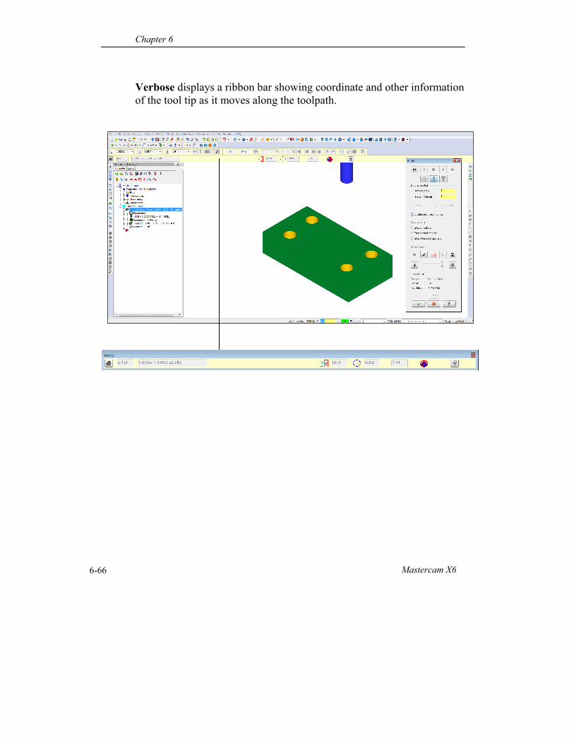
Verbose displays a ribbon bar showing coordinate and other information of the tool tip as it moves along the toolpath.
Drill Toolpaths
Mastercam Handbook Volume 1 6-67
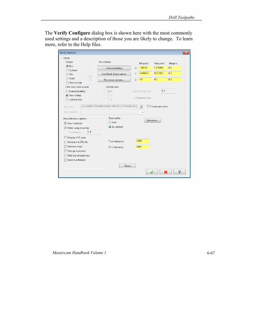
The Verify Configure dialog box is shown here with the most commonly used settings and a description of those you are likely to change. To learn more, refer to the Help files.
Chapter 6
Mastercam X6 6-68
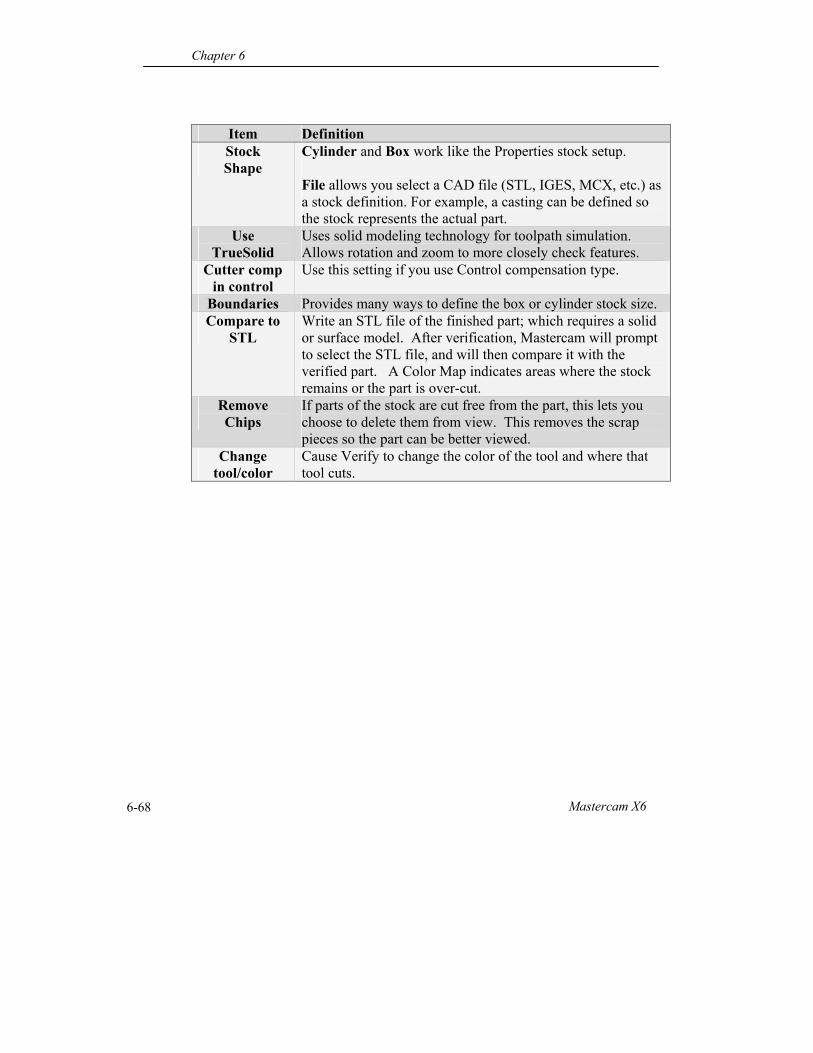
Item Definition Stock Shape
Cylinder and Box work like the Properties stock setup. File allows you select a CAD file (STL, IGES, MCX, etc.) as a stock definition. For example, a casting can be defined so the stock represents the actual part.
Use TrueSolid
Uses solid modeling technology for toolpath simulation. Allows rotation and zoom to more closely check features.
Cutter comp in control
Use this setting if you use Control compensation type.
Boundaries Provides many ways to define the box or cylinder stock size. Compare to
STL Write an STL file of the finished part; which requires a solid or surface model. After verification, Mastercam will prompt to select the STL file, and will then compare it with the verified part. A Color Map indicates areas where the stock remains or the part is over-cut.
Remove Chips
If parts of the stock are cut free from the part, this lets you choose to delete them from view. This removes the scrap pieces so the part can be better viewed.
Change tool/color
Cause Verify to change the color of the tool and where that tool cuts.
Drill Toolpaths
Mastercam Handbook Volume 1 6-69
Post Process
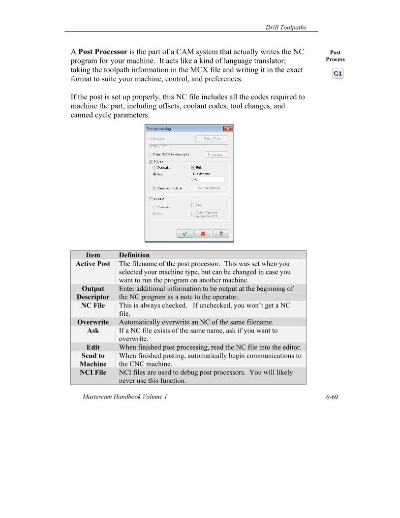
A Post Processor is the part of a CAM system that actually writes the NC program for your machine. It acts like a kind of language translator; taking the toolpath information in the MCX file and writing it in the exact format to suite your machine, control, and preferences. If the post is set up properly, this NC file includes all the codes required to machine the part, including offsets, coolant codes, tool changes, and canned cycle parameters.
Item Definition Active Post The filename of the post processor. This was set when you
selected your machine type, but can be changed in case you want to run the program on another machine.
Output Descriptor
Enter additional information to be output at the beginning of the NC program as a note to the operator.
NC File This is always checked. If unchecked, you won’t get a NC file.
Overwrite Automatically overwrite an NC of the same filename. Ask If a NC file exists of the same name, ask if you want to
overwrite. Edit When finished post processing, read the NC file into the editor.
Send to Machine
When finished posting, automatically begin communications to the CNC machine.
NCI File NCI files are used to debug post processors. You will likely never use this function.
Chapter 6
Mastercam X6 6-70
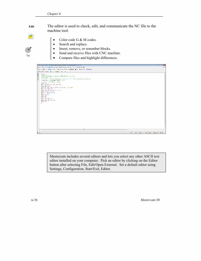
Edit
Mastercam includes several editors and lets you select any other ASCII text editor installed on your computer. Pick an editor by clicking on the Editor button after selecting File, Edit/Open External. Set a default editor using Settings, Configuration, Start/Exit, Editor.
The editor is used to check, edit, and communicate the NC file to the machine tool.
Color code G & M codes. Search and replace. Insert, remove, or renumber blocks. Send and receive files with CNC machine. Compare files and highlight differences.
Drill Toolpaths
Mastercam Handbook Volume 1 6-71
Communicate RS-232 communications is the most common way to transfer NC programs to the CNC machine. It is a relatively old and slow standard compared to some more modern alternatives, but works quite well for smaller files. Very large files, like those typical of mold and complex prototypes, may take a very long time to transmit via serial communications. For example, a 1MB file will take nearly two minutes to transfer. Other ways to communicate depend on your machine options, but could include:
Floppy disc drive (limited to 1.44MB) Ethernet card Flash memory
Some machines, especially older CNC’s, have very limited memory. In this case, you may need to DNC the program to the CNC. DNC sends only part of the program to the CNC at a time but requires the PC remain in constant communication with the CNC. These general steps assume your machine, PC, and cable are configured properly: Step 1: Get your machine ready to receive. Step 2: Read the file into CIMCO-EDIT. Step 3: Select Transmission, Send, and pick the machine name from the list. To send a program from the machine back to the computer: Step 1: In Cimco, select File, New. Step 2: Select Transmission, Receive Send, and pick the machine name from the list. Type in a file name to assign the new file. Step 3: Go to the machine and send the file.
Chapter 6
Mastercam X6 6-72
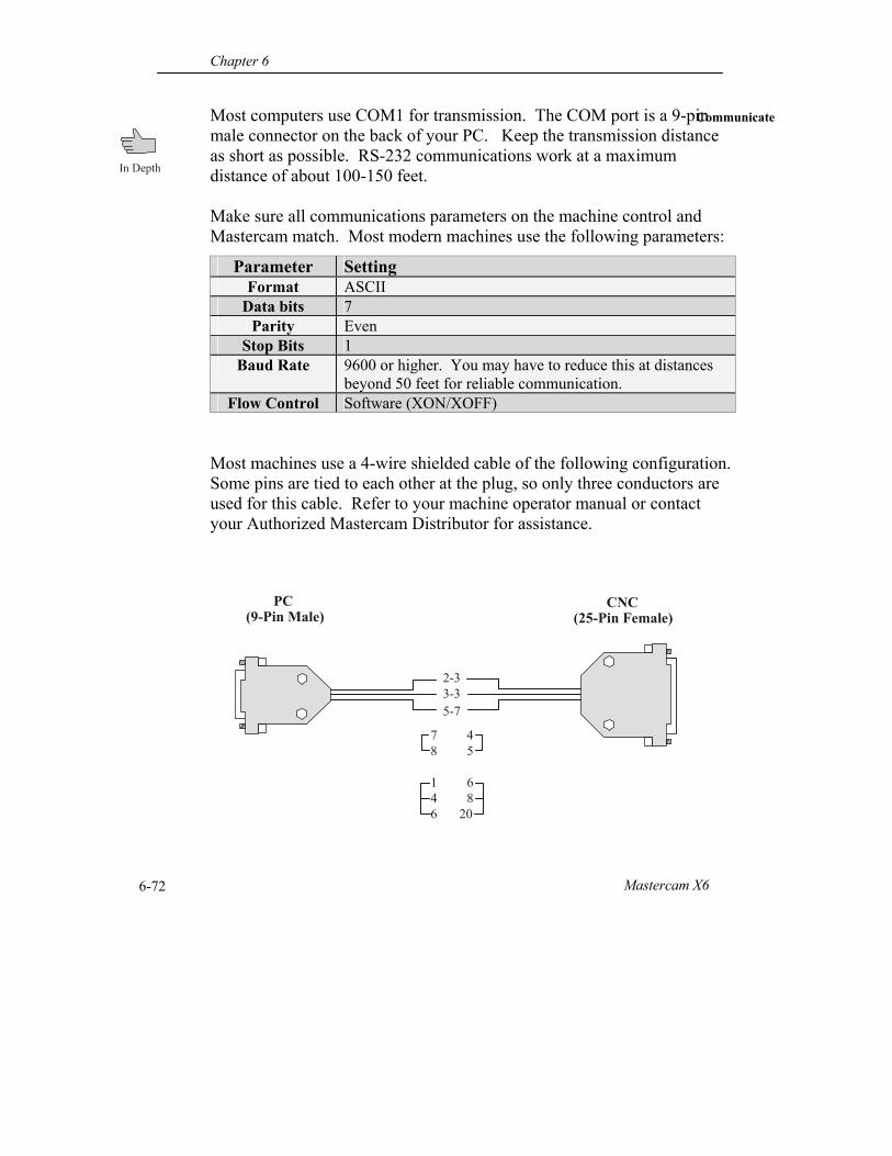
Communicate Most computers use COM1 for transmission. The COM port is a 9-pin male connector on the back of your PC. Keep the transmission distance as short as possible. RS-232 communications work at a maximum distance of about 100-150 feet. Make sure all communications parameters on the machine control and Mastercam match. Most modern machines use the following parameters:
Most machines use a 4-wire shielded cable of the following configuration. Some pins are tied to each other at the plug, so only three conductors are used for this cable. Refer to your machine operator manual or contact your Authorized Mastercam Distributor for assistance.
Parameter Setting Format ASCII
Data bits 7 Parity Even
Stop Bits 1 Baud Rate 9600 or higher. You may have to reduce this at distances
beyond 50 feet for reliable communication. Flow Control Software (XON/XOFF)
20
PC (9-Pin Male)
CNC (25-Pin Female)
2-3 3-35-7
78
146
45
68
Drill Toolpaths
Mastercam Handbook Volume 1 6-73
Automated Hole
Processing
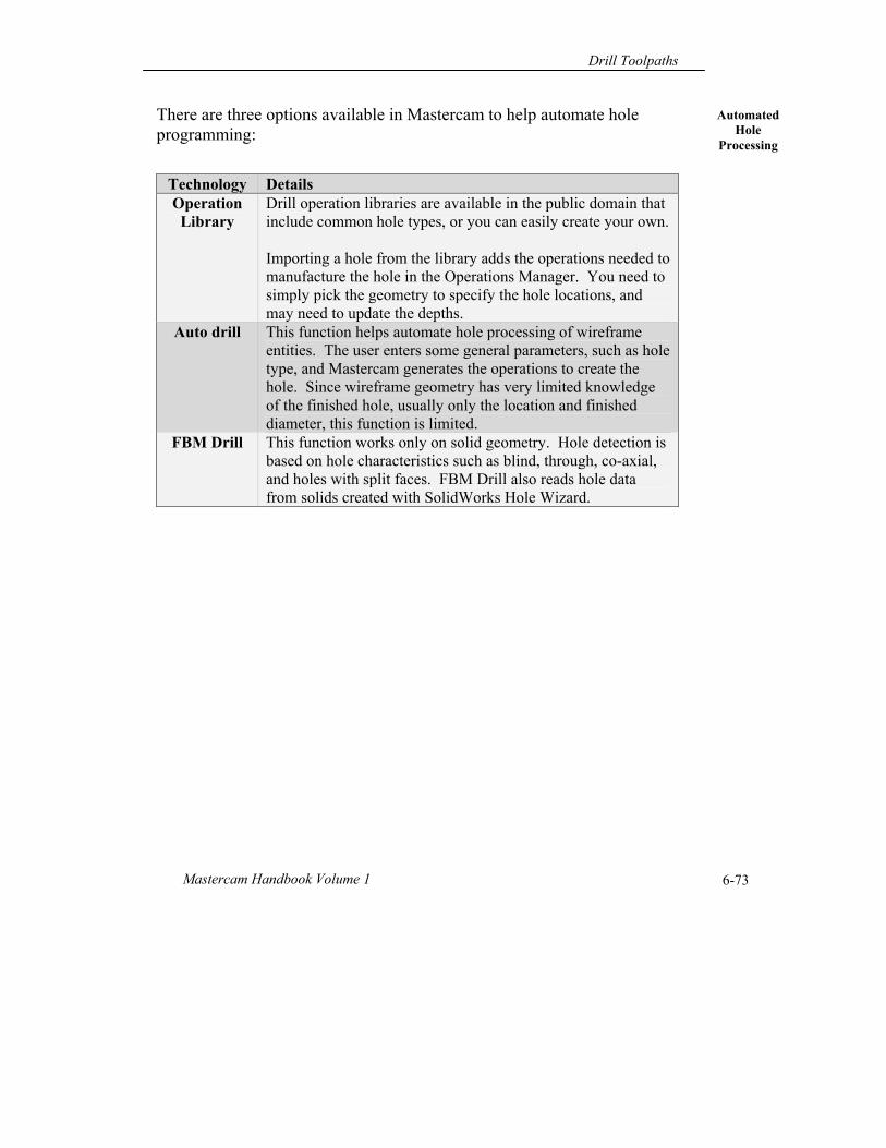
There are three options available in Mastercam to help automate hole programming:
Technology Details Operation
Library Drill operation libraries are available in the public domain that include common hole types, or you can easily create your own. Importing a hole from the library adds the operations needed to manufacture the hole in the Operations Manager. You need to simply pick the geometry to specify the hole locations, and may need to update the depths.
Auto drill This function helps automate hole processing of wireframe entities. The user enters some general parameters, such as hole type, and Mastercam generates the operations to create the hole. Since wireframe geometry has very limited knowledge of the finished hole, usually only the location and finished diameter, this function is limited.
FBM Drill This function works only on solid geometry. Hole detection is based on hole characteristics such as blind, through, co-axial, and holes with split faces. FBM Drill also reads hole data from solids created with SolidWorks Hole Wizard.
Chapter 6
Mastercam X6 6-74
What You
Learned
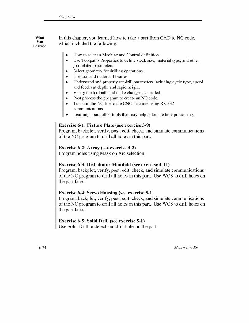
In this chapter, you learned how to take a part from CAD to NC code, which included the following:
How to select a Machine and Control definition. Use Toolpaths Properties to define stock size, material type, and other
job related parameters. Select geometry for drilling operations. Use tool and material libraries. Understand and properly set drill parameters including cycle type, speed
and feed, cut depth, and rapid height. Verify the toolpath and make changes as needed. Post process the program to create an NC code. Transmit the NC file to the CNC machine using RS-232
communications. Learning about other tools that may help automate hole processing.
Exercise 6-1: Fixture Plate (see exercise 3-9) Program, backplot, verify, post, edit, check, and simulate communications of the NC program to drill all holes in this part. Exercise 6-2: Array (see exercise 4-2) Program holes using Mask on Arc selection. Exercise 6-3: Distributor Manifold (see exercise 4-11) Program, backplot, verify, post, edit, check, and simulate communications of the NC program to drill all holes in this part. Use WCS to drill holes on the part face. Exercise 6-4: Servo Housing (see exercise 5-1) Program, backplot, verify, post, edit, check, and simulate communications of the NC program to drill all holes in this part. Use WCS to drill holes on the part face. Exercise 6-5: Solid Drill (see exercise 5-1) Use Solid Drill to detect and drill holes in the part.

Drill Toolpaths
Mastercam Handbook Volume 1 6-75
Notes:

Chapter 6
Mastercam X6 6-76
Thank you for previewing the
Mastercam X6 Handbook Volume 1.
We hope you like what you see. If you haven’t already, be sure to check out the Table of Contents included at the beginning of this sample for a full listing of topics covered. If you found this excerpt useful, we’re certain the rest of the book will help you along your way to mastering Mastercam.
To thank you for considering our Mastercam Training Solutions,
>> We would like to extend a special offer to you. Take 10% off your next purchase of any Mastercam X6 Handbook (Print or eBook formats) at our eMastercam Store using coupon code:
X6TRAIN If you need some help deciding which title is right for you, email us at [email protected] or use our live chat feature in the store. Likewise, feel free to drop us any suggestions of what you might like to see in future products.
>> Be in the loop! Also consider signing up for the eMastercam.com Community Updates email list. You’ll receive more offers like this and be the first to know about new product releases and free downloads.
Sign me up!