Embed Size (px)
Citation preview
Samal Island-Davao City Connector (SIDC) Project MINIMUM PERFORMANCE STANDARDS AND SPECIFICATIONS (MPSS) Department of Public Works and Highways (DPWH) Government of Republic of Philippines DIVISION A2: SPECIFIC REQUIREMENTS
SIDC-ER-Div-A2-01_Final.docx Part A2 Page 1 of 108 Tender Issue 01 September 2020
1 GENERAL
Scope
The Specific Requirements state the specific design and construction requirements for all the permanent works components of the Samal Island - Davao City Connector (SIDC) Project, herein referred to as the Project. Refer to Employer’s Requirement Division A1 on the submission and review requirements for both permanent and temporary works, and in particular, the submission timeline for the Preliminary Design Report and the Detailed Engineering Design Report.
The Contractor shall design, execute and complete the Works in accordance with these Employer’s Requirements. The Contractor shall construct the Works in accordance with the Contractor’s design, in a manner and with the materials as specified in the Contractor’s design, as reviewed and approved by the Employer.
This Division A2 of the Employer’s Requirement (ER) shall be read in conjunction with other parts of the Employer’s Requirements and other parts of the Contract. Unless stated otherwise, in the event of any conflict or discrepancy between this Division A2 and Division B Specification of the Employer’s Requirements, Division A2 of the Employer’s Requirements shall take precedence over Division B Specification.
Upon request by the Engineer or Employer, the Contractor shall set up a series of detailed briefing meetings to present design calculations, drawings, construction methods in detail explaining and demonstrating, with the use of renderings, computer generated perspectives and physical working model, as and where appropriate, exactly how the Employer’s Requirements have been implemented and illustrating how the Employer’s comments have been incorporated in the design.
It shall be noted that notwithstanding any description given in the Employer’s Requirements, the Contractor shall allow for all site investigation, clearance, demolition, excavation, ground improvement, relocation, removal and disposal of any material encountered. For the avoidance of doubt, “any material” means any material of any nature whatsoever (whether naturally occurring or man-made) which may affect the execution of the Work, including but not limited to polluted materials, mud, silt, sand, clay, rock, boulders, ship wrecks, chains, anchors, cables or existing structures and utilities.
The Contractor shall be responsible for the design, execution and removal for all Temporary Works required for the permanent work construction. All Temporary Works design shall be reviewed and certified by Temporary Works Checker(s).
The Contractor shall submit method statements for all temporary works to the Engineer’s for review in accordance with the Review Procedure prior to construction.
General Design Specification
The design of the Works shall be developed in accordance with these Employer's Requirements, the Contractor's Proposals and other requirements of the Contract.
The Works shall be designed and constructed using proven up-to-date good practice and to the latest available standards. The Contractor’s proposal shall in any case, be subject to the Employer's opinion, and not be less than or inferior to those described in the Employer's Requirements.
Design Standard
The codes of practice and standards for design shall be as stated in the relevant parts of the Employer’s Requirements, unless otherwise demonstrated by the Contractor to the
Samal Island-Davao City Connector (SIDC) Project MINIMUM PERFORMANCE STANDARDS AND SPECIFICATIONS (MPSS) Department of Public Works and Highways (DPWH) Government of Republic of Philippines DIVISION A2: SPECIFIC REQUIREMENTS
SIDC-ER-Div-A2-01_Final.docx Part A2 Page 2 of 108 Tender Issue 01 September 2020
satisfaction of the Employer that the codes or standards are inapplicable or inappropriate for the design or construction of the permanent Works designed by the Contractor.
Additional codes, standards and specifications proposed by the Contractor shall be related to standards/codes in the Philippines and the AASHTO specifications for civil engineering and other works. Only in the absence of such relevant or appropriate codes and standards shall codes and standards from other jurisdictions be permitted, subject to such other codes and standards being, as demonstrated by the Contractor and as agreed with the Employer and the relevant authorities, suitable for use in the design of the Works.
The Contractor shall be responsible for checking and following all necessary design documents for the proper execution of the Works.
Drawings
A list of Employer’s Drawings (herein called Drawings) showing the scope of the Works is enclosed in Division A3 of the Employer’s Requirements. The specific requirements defined in this Division A2 shall be read in conjunction with the requirements on the Drawings.
The design shown on the Conceptual Design Drawings in the tender library is for reference only. The Contractor is required to develop his own scheme and Detailed Engineering Design in compliance with the Employer’s Requirements.
Where the Employer’s Drawings show details that the Contractor has to adopt, the Contractor shall be responsible for developing the details further as required.
Specification
Where the term ‘Specification’ is used in the Employer’s Requirement, it shall mean the project Specification as described in Section 3.4 of Employers Requirements Division A1.
Dimensions
Where a dimension is given a permitted range, the Contractor shall determine the dimension to be adopted within this range. Where dimensions are not given, the Contractor shall determine the dimensions. The tolerances on the dimensions for construction shall be those given in Section 3.26.
2 HIGHWAY ALIGNMENT
General
The proposed Works, including roads, bridge structures, embankments, etc. shall all be within the Right of Way (ROW) boundary shown on Drawings IPIF1/SIDC/DEF/GEN/0060 to 0067.
The Contractor shall refer to Highway Design Basis in Annex B to the Employer’s Requirements Division A2 for highway alignment design.
The Contractor shall submit Preliminary Design and Detailed Design for Highway Alignment and Roadworks in accordance with the Review Procedure in Employer’s Requirements Division A1 General Requirements. The submissions shall cover the design of the Works as described in this Section, Highway Design Basis Annex B to the Employer’s Requirements Division A2, Sections 7 and 10.1.
Samal Island-Davao City Connector (SIDC) Project MINIMUM PERFORMANCE STANDARDS AND SPECIFICATIONS (MPSS) Department of Public Works and Highways (DPWH) Government of Republic of Philippines DIVISION A2: SPECIFIC REQUIREMENTS
SIDC-ER-Div-A2-01_Final.docx Part A2 Page 3 of 108 Tender Issue 01 September 2020
3 BRIDGE STRUCTURES
General
Scope
3.1.1.1 The Bridge Structures in the Employer’s Requirement shall consist of all the bridge structures’ requirements in this project, including the bridge foundations, substructure and superstructure, abutments and all associated electrical and ancillary works that are necessary for proper function.
Definitions
Navigation Clearance - shall mean the horizonal and vertical clearances as described below;
Horizontal clearance - a minimum 230m wide horizontal clearance between structures shall be provided. The 230m comprises a 150m wide navigation channel for one-way ship traffic, with a minimum 40m buffer on both sides of the navigation channel, as defined on Drawing IPIFI/SIDC/DEF/MAR/5000.
Vertical clearance - a minimum vertical clearance above mean higher high water level to the superstructure soffit shall be 47m in the portion of superstructure crossing the navigation channel, and 43m in the portion of superstructure outside the navigation channel, but within the horizontal clearance, as defined on Drawing IPIFI/SIDC/DEF/MAR/5000.
The Navigation Clearance shall have a minimum depth below mean higher high water level of 17.8m, or a depth based on the draft of the largest vessels passing underneath the bridge, whichever is deeper, as defined on Drawing IPIFI/SIDC/DEF/MAR/5000. The depth shall be agreed with the Employer, Philippines Coastguard and any other relevant authorities.
Navigation Bridge – The portion of the Project that consists of the bridge structure that extends over the Navigation Clearance and extends between the deck expansion joints on either side of the Navigation Clearance. The Navigation Bridge includes the extradose bridge superstructure, towers, columns, adjacent back span piers and adjacent expansion joints.
Approach Bridges – The portions of the Project that consist of the bridge structures not included as part of the Navigation Bridge. This comprises the marine viaduct west, land viaduct west and bridge interchange ramps west (on the Davao side) and marine viaduct east and land viaduct east (on the Samal side).
Bridge Structures Drawings
3.2.4.1 The Bridge Structures Drawings include:
the arrangement and dimensional requirements of the principal structural elements of the Bridge Structures where applicable;
constraints to the bridge geometry to account for the vertical and horizontal clearances of the Navigation Clearance and Maximum Allowable Top Elevation (MATE) of structures, imposed by nearby Francisco Bangoy International Airport.
Note that the Contractor shall secure the necessary Height Clearance Permit (HCP) from Civil Aviation Authority of the Philippines (CAAP), prior to starting construction of the Project.
3.2.4.2 The configuration of the road carriageway, sidewalk and utility corridor shall comply with the dimensions given in the Drawings.
Samal Island-Davao City Connector (SIDC) Project MINIMUM PERFORMANCE STANDARDS AND SPECIFICATIONS (MPSS) Department of Public Works and Highways (DPWH) Government of Republic of Philippines DIVISION A2: SPECIFIC REQUIREMENTS
SIDC-ER-Div-A2-01_Final.docx Part A2 Page 4 of 108 Tender Issue 01 September 2020
3.2.4.3 All information regarding the existing terrain (including ground and seabed levels) shown on the Drawings are indicative. No warranty is given to the accuracy of this information and the Contractor shall be responsible for all topographic information required for the design, execution and completion of the Bridge Structures. The Contractor shall obtain all necessary information and take it into account in the design and execution of the Works.
3.2.4.4 A list of the Drawings can be found within Division A3 of the Employer’s Requirements.
Aesthetic Design
Overall aesthetics and architectural detailing of the structural and non-structural members shall be given proper attention. The Contractor shall develop an Aesthetics Strategy Report presenting a comprehensive strategy and theme, together with supporting design guidelines for the Project. The Aesthetics Strategy Report shall be submitted to the Engineer for review and approval by the Employer.
Structural Design Basis
Structural design requirements are defined in further detail in the Structural Design Basis in Annex C to the Employer’s Requirements Division A2. The structural design shall comply with the requirements in the Structural Design Basis as well as those in other parts of the Employer’s Requirements.
General Requirements
The overall requirements for the location are described on the Drawings.
The Contractor shall comply with the following requirements:
The location of the interchange ramps on Davao, the roundabout on Samal Island and the Navigation Clearance shall be provided as shown on Drawings IPIF1/SIDC/DEF/CVL/1000 to 1008 and IPIFI/SIDC/DEF/MAR/5000.
For the Navigation Bridge:
(i) The structure shall be a three-span extradose bridge. The centre span shall extend over the Navigation Clearance. The mid-point of the centre span shall be at the centre of the navigation channel, as defined on drawing IPIF1/SIDC/DEF/MAR/5000.
(ii) The bridge structure shall be symmetrical about the mid-point of the centre span.
(iii) The length of superstructure shall be either a single steel-concrete composite box girder or a single concrete box girder or a combination of both options.
(iv) Steel orthotropic deck shall not be permitted for the superstructure.
(v) The position of the towers shall be in a central arrangement i.e. single vertical tower located at the centreline of the bridge deck cross section. The towers shall be located on each side of the navigation channel. The towers shall be vertically plum. The top of the towers shall comply with the MATE of +73 m above EGM2008 Geoid.
(vi) The superstructure shall be supported by a combination of columns and cable system connected to the deck and towers. The cables shall be symmetrical about the towers, and in one central plane or two parallel planes attached to the same tower.
Samal Island-Davao City Connector (SIDC) Project MINIMUM PERFORMANCE STANDARDS AND SPECIFICATIONS (MPSS) Department of Public Works and Highways (DPWH) Government of Republic of Philippines DIVISION A2: SPECIFIC REQUIREMENTS
SIDC-ER-Div-A2-01_Final.docx Part A2 Page 5 of 108 Tender Issue 01 September 2020
(vii) A minimum clearance of 1m shall be provided between the stay cables and the traffic envelope at the face of the carriageway vehicle restraint system.
(viii) Concrete encased cable system shall not be permitted. The stay cables shall comply with the requirements in Specifications Part F Section 51.
(ix) The Navigation Bridge support structures including columns and foundations shall be located outside of the Navigation Clearance, as defined in Section 3.2.1.
(x) Under all service load combinations, and during inspection via under bridge inspection equipment, the bridge superstructure shall provide the required vertical and horizontal navigation clearance defined in Section 3.2.1.
(xi) Long term effects of concrete creep and shrinkage shall be accounted for to ensure the required vertical clearances defined in Sections 3.2.1 and 3.5.2(x), and residual cambers are maintained for the design service life of the bridge.
For the Approach Bridges
(i) The lengths of superstructure over land shall be concrete I-girders, concrete box girders or steel-concrete composite box girders or a combination of these options.
(ii) The lengths of superstructure over water, shall be either concrete I-girders or concrete box girders unless the Contractor seeks written approval from the Employer to adopt steel-concrete composite box girder. If the Contractor elects this option, then full justification shall be provided to the Employer to explain why this option shall be adopted over the other two options. Key considerations included in the justification should include, but not limited to, effect on programme, cost savings, durability, etc.
(iii) Steel-concrete composite open section plate girders shall not be permitted for the bridge superstructure.
(iv) Steel orthotropic deck shall not be permitted for the superstructure.
(v) For approach bridges over water, the minimum vertical clearance above mean highest high water level to the superstructure soffit shall be 10m, and the minimum horizontal clearance shall be 50m unless otherwise agreed with the Employer and relevant authorities, i.e. Philippines Coastguard, etc.
(vi) For approach bridges over land, the minimum vertical clearance shall refer to the Highway Design Basis Annex B to the Employer’s Requirements Division A2.
(vii) Under all service load combinations, the bridge superstructure shall provide the required vertical and horizontal clearances.
(viii) Long term effects of concrete creep and shrinkage shall be accounted for to ensure the required vertical clearances and residual cambers are maintained for the design service life of the bridge.
Where structural depth is less than 1.8m, box girder deck shall not be permitted.
Where there is a change or discontinuity in bridge shape or form across a movement joint (e.g. transition from box girder to multiple I-girders), the deck slab cantilever shall match each other for aesthetic reasons, or as proposed by the Contractor for agreement by the Employer. In addition, at the end of internally accessible bridge deck (e.g. deck cell of box girder), the deck cell shall be blocked off by blockwork, or removable steel mesh screen if access via the end of box
Samal Island-Davao City Connector (SIDC) Project MINIMUM PERFORMANCE STANDARDS AND SPECIFICATIONS (MPSS) Department of Public Works and Highways (DPWH) Government of Republic of Philippines DIVISION A2: SPECIFIC REQUIREMENTS
SIDC-ER-Div-A2-01_Final.docx Part A2 Page 6 of 108 Tender Issue 01 September 2020
girder is required. The blockwork surface shall match with the as-built concrete deck for aesthetic consideration.
Half joints shall not be permitted.
Wind Tunnel Testing
3.5.3.1 Wind tunnel testing shall be undertaken to determine the force coefficients for the deck for both the partially erected and completed Navigation Bridge. The effect of the wind on the Navigation Bridge, for both the partially erected and completed stages, shall be determined so as to ensure that there will be no detrimental effects to the Navigation Bridge or to the comfort of users. In particular, the response of the Navigation Bridge to turbulent wind and the vortex shedding response in smooth flow wind shall need to be assessed by the Contractor.
3.5.3.2 A complete Wind Tunnel Testing Report shall be submitted to the Engineer in accordance with the Review Procedure in Employer’s Requirements Division A1 General Requirements.
3.5.3.3 The following drag coefficients shall be adopted in the Design, as a minimum, for stay cables.
Transverse winds, CD = 0.8 for transverse winds
Longitudinal winds, CD = CD,O sin3A Where CD,O = 1.2 and A = angle of stay cable to the horizontal
Erection Stage Analysis and Measurements During the Course of the Works
3.5.4.1 Prior to commencement of construction, the Contractor shall carry out erection stage analysis for all erection stages based on the actual erection loads to determine the geometry of the completed structure and hence derive the stay installation forces and bridge control geometry necessary to arrive at the Reference Condition, as defined in Section 3.26. The calculations shall include tables containing values of the anticipated stay cable lengths and tensions in each stay cable at a corresponding erection stage.
3.5.4.2 Immediately after erection of a pair of stay cables the Contractor shall measure the installed length of the tension in those cables. The Contractor shall ascertain that the length of the stay cables is as anticipated and the tension in the stay cable shall be within 5% of the values calculated for that erection stage. All such records shall be submitted to the Engineer in accordance with the Review Procedure. If the specified tolerances are exceeded. Adjustment procedures shall be developed and submitted to the Engineer for agreements before being carried out by the Contractor.
3.5.4.3 The erection stage calculations shall be updated after erection of a pair of corresponding main span and back span stay cables based on an updated survey of the bridge and the actual erection loads and conditions at the time of the stay cable installation. The surveys shall comprise the bridge deck and tower. Survey points shall be weather resistant points incorporated into the structure. Surveys shall be carried out in the pre-dawn hours to minimise temperature effects.
3.5.4.4 Permanent records shall be established and submitted to the Engineer in accordance with the Review Procedure for each stay installation. Such records shall include survey records; date, time, and ambient temperatures; stay cable lengths; stay cable forces, jack extension measurement; locknut setting; deck loading conditions and all other special records necessary and sufficient to establish the conditions under which the stay cable was installed.
3.5.4.5 Adjustment of the stay cables shall be performed with the precision of 5% of elongation or shortening relative to the initial length of cable (L0) and 3% on the measurement of the tension load in the stay cable.
Samal Island-Davao City Connector (SIDC) Project MINIMUM PERFORMANCE STANDARDS AND SPECIFICATIONS (MPSS) Department of Public Works and Highways (DPWH) Government of Republic of Philippines DIVISION A2: SPECIFIC REQUIREMENTS
SIDC-ER-Div-A2-01_Final.docx Part A2 Page 7 of 108 Tender Issue 01 September 2020
3.5.4.6 At completion of deck erection works (i.e, before application of permanent loads like surfacing, etc), a check of the stay cable lengths and forces shall be made by the Contractor. The stay cable forces shall be within 5% of the theoretical values when the geometry is within the specified tolerances. If the specified tolerance exceeded, adjustment procedures, shall be developed by the Contractor and submitted to the Engineer in accordance with the Review Procedure prior to executing such procedures.
3.5.4.7 At completion of the bridge, a check of the stay cable lengths and forces under the bridge reference condition shall be made by the contractor and submitted to the Engineer in accordance with the Review Procedure. The stay cable forces shall within 5% of the theoretical values when the geometry is within the specified tolerances. If the specified tolerances are exceeded, adjustment procedures shall be developed by the contractor and submitted to the Engineer in accordance with the Review Procedure prior to executing such procedures.
3.5.4.8 Permanent records shall be prepared by the Contractor to include the as-built vertical alignment of the deck along center line as well as the deflections of the towers. The records shall be compared by the Contractor with the construction of vertical alignment and if the specified tolerances are exceeded, adjustment procedures shall be developed by the Contractor and submitted to Engineer in accordance with the Review Procedure prior to executing such procedures.
Foundations
Foundations comprise land and marine structures supporting the bridge superstructure, columns, end bents and towers.
Marine foundations may be gravity based or piled structures provided the loads can be safely and suitably transmitted to the ground whilst satisfying the strength and serviceability requirements defined in the Structural Design Basis in Annex C to the Employer’s Requirements Division A2.
Foundations combining load resistance by ground bearing and piles shall not be permitted.
Marine foundations may be steel, concrete or steel-concrete composite hybrid structures provided the strength, serviceability, durability and corrosion protection requirements defined in the Structural Design Basis in Annex C to the Employer’s Requirements Division A2 are met.
Marine foundations shall not be fully submerged at highest tide level (including sea level rise) and taking due allowance for expected settlement. The top surface of the foundation shall have a minimum 2.5% gradient to prevent water ponding.
Marine foundations shall be dimensioned to prevent direct ship impact on the bridge columns and towers.
The top of all pile caps for piers on land shall be at least 1500mm below the proposed ground level.
The marine foundations shall be located so that they do not obstruct the required minimum Navigation Clearance. Refer to Section 3.2.1 for details of the required Navigation Clearance.
The below-water dimensioning of the foundations shall not impinge on the Navigation Clearance, taking the maximum draft vessel as defined in the Structural Design Basis in Annex C to the Employer’s Requirements Division A2.
Marine foundations shall not include structure that is a hazard to general navigation such as submerged towers remote from the main tower support.
Samal Island-Davao City Connector (SIDC) Project MINIMUM PERFORMANCE STANDARDS AND SPECIFICATIONS (MPSS) Department of Public Works and Highways (DPWH) Government of Republic of Philippines DIVISION A2: SPECIFIC REQUIREMENTS
SIDC-ER-Div-A2-01_Final.docx Part A2 Page 8 of 108 Tender Issue 01 September 2020
The Contractor shall define as part of the design of the Works the pile construction tolerances for verticality and location and confirm that they are compatible with the construction method chosen for the pile cap and bridge superstructure.
Additional ground investigation shall be carried out in accordance with the requirements in Section 4.6.
Excavation for pile caps shall be backfilled and landscaped up to the finished ground level.
Abutments
The design of the Works shall permit maintenance operatives to gain access to the abutments, the bearings (if any) and movement joints from ground level. The design shall allow maintenance and replacement of bearings and movement joints at the abutments.
Seat type abutments shall not be supported on MSE embankments or walls.
Access and Maintenance
The Contractor shall make provision in the design of the Works for future inspection and maintenance of all elements throughout the design life.
The Contractor shall make provision for access for the following purposes:
cleaning, maintenance and inspection;
jacking, removal / replacement of bearings and seismic isolation devices;
removal / replacement of external tendon;
removal / replacement of stay cables;
removal / replacement of movement joints; and
inspection of the interior and exterior of the Permanent Works.
Access from ground level shall be provided, where possible, at both ends of each continuous strip of internally accessible bridge (e.g. deck cell of box girder). Access ladders with lockable door shall be provided where required to provide a safe access route. Where such access is provided at a pier with column(s), hand rail or barrier at the top of pier shall be provided to ensure safety of personnel during inspection. Where the continuous strip of internally accessible bridge stops at the marine section, and hence access from ground level is not possible, alternative arrangement for safe access to inside of the box girder shall be provided. The arrangement shall be proposed by the Contractor for review and approval. Such access arrangement shall comply with the requirements in the ER and shall not require closure of the road.
Access from the road level via deck manhole access shall be provided at both ends of each continuous strip of internally accessible bridge to facilitate installation and replacement of utilities and cables in the deck cell. If the continuous strip of bridge deck is longer than 1.0km, extra accesses shall be provided as discussed with and approved by the Engineer.
The access arrangements to be provided shall be in accordance with the following requirements:
access points shall be placed in such positions as to give convenient access, and where their use would cause minimum interference to traffic;
all access points and access ways within voids shall be suitably sized and designed to allow for the evacuation of a casualty, on a stretcher and the like if necessary;
Samal Island-Davao City Connector (SIDC) Project MINIMUM PERFORMANCE STANDARDS AND SPECIFICATIONS (MPSS) Department of Public Works and Highways (DPWH) Government of Republic of Philippines DIVISION A2: SPECIFIC REQUIREMENTS
SIDC-ER-Div-A2-01_Final.docx Part A2 Page 9 of 108 Tender Issue 01 September 2020
specific emergency routes and exits shall be identified clearly by signs and shall be provided with lighting;
access points shall be carefully located and detailed so as to minimise their visibility to passing traffic;
all access equipment shall be capable of withstanding the prevailing environmental conditions including ingress of dust and water, wind and natural movement;
permanent access ladders or steps, as appropriate, shall be provided at changes in level along access routes;
all walking surfaces shall avoid details which create a risk of tripping and shall be self-draining;
permanent lighting with power supply shall be provided for access routes, access chambers and deck cell in accordance with Section 14; lighting levels shall be a minimum of 50 lux;
warning notices and signs shall be provided to all electrical power boards and the like where the operation may affect the safety of persons using the voids;
all access points to inspection chambers and voids and the like shall be capable of being secured from unauthorised access by means of lockable steel doors or grills; and
public access to any facilities provided for bridge inspection or maintenance shall be prevented by means of suitable barriers, covers and the like and colonisation of accessible areas by plants, animals or birds shall be prevented by the application of suitable measures.
Where voided elements, e.g. box girder superstructures, voided columns, inspection galleries and the like are provided, they shall be of sufficient size to allow internal inspection.
Where bridge bearings and/ or seismic isolation devices are used in the Works they shall be replaceable without requiring the removal of any structural concrete or welding of attachments to the Permanent Works. For internally accessible bridges, a safe access route shall be provided to facilitate the inspection of bearings and/ or seismic isolation (if any) at the movement joint piers. Inspection pit at the top of column shall be provided to facilitate the inspection of these bearings and seismic isolation devices. For other piers with bearings/seismic isolation device (if any), safe access arrangement for inspection of such shall be provided. The arrangement shall be proposed by the Contractor for review and approval.
Provisions shall be made to allow for jacking from the substructure or supporting structure during bearing or seismic isolation device replacement.
The Contractor shall provide the Bridge Signage as specified in Section 54 of Part F of the Specification to provide orientation to the inspection personnel.
The design of the Works shall ensure that replacement of all replaceable components shall be possible whilst maintaining traffic flows as specified in the Structural Design Basis in Annex C to this Employer’s Requirements Division A2.
Drainage
For the Navigation Bridge, run off from bridge deck shall be collected in pipework and carried away to suitable locations where it can then be discharged into the sea to avoid discharge directly over the Navigation Clearance.
Samal Island-Davao City Connector (SIDC) Project MINIMUM PERFORMANCE STANDARDS AND SPECIFICATIONS (MPSS) Department of Public Works and Highways (DPWH) Government of Republic of Philippines DIVISION A2: SPECIFIC REQUIREMENTS
SIDC-ER-Div-A2-01_Final.docx Part A2 Page 10 of 108 Tender Issue 01 September 2020
For Approach Bridge Structures over the sea, runoff from bridge decks may be directly discharged to the sea through gullies located at the edge of the sidewalk, utilities corridor and/or carriageways.
For approach Bridge Structures over land, runoff from bridge decks shall be carried off the bridge in pipework into the adjacent proposed or existing roadway drainage system.
The Contractor shall make allowance for the deflected shape of the bridge and ensure that positive drainage is provided under all service limit state (“SLS”) conditions.
Drain holes shall be provided at the soffit of closed superstructures (i.e. bottom slab) to ensure that water (and any other liquid) can drain and not pond within the superstructure.
Bearings
Where bearings are proposed by the Contractor, the Contractor shall ensure that the inspection and replacement of all bearings shall be possible without modification to the adjacent permanent structure, whilst maintaining traffic on the carriageway as specified in the Structural Design Basis in Annex C to this Division A2 of Employer’s Requirements. The Contractor shall provide a support system to facilitate future replacement of the bearings.
The bearings shall comply with the construction specification in Section 18 of Part F of the Specification.
Seismic Isolation Devices / Seismic Energy Product
If seismic isolation bearings are proposed by the Contractor, the design and construction of these bearings shall comply with Section 52 of Part F of the Specification. The intention to use seismic isolation bearings shall be stated in the Preliminary Engineering Design Report submission for review and approval.
The requirements in Section 3.10.1 shall also apply to seismic isolation devices / energy products.
If the Contractor elects to use other types of seismic isolation devices, the Contractor shall submit their proposal at the Preliminary Engineering Design Report for the review of the Engineer. Such proposal shall include suitable design standard and construction specification of such device for the review and approval of relevant local authorities and the Engineer.
Movement / Expansion Joints
Structure movement joints shall be capable of accommodating all design translations and rotations between the adjacent superstructures without damage. The Contractor shall ensure that they can be removed and replaced during the design lifetime of the bridge without modification to the Bridge Structures.
The Contractor shall provide structure movement joints across the full width of each carriageway, sidewalk and utilities corridor. The joints shall incorporate a waterproofing system across the full width of each superstructure and detailed in such a way to prevent water percolating beneath the waterproofing membrane, and comply with the requirements in DMRB CD 358 Waterproofing and surfacing of concrete bridge decks.
Structure movement joints shall be of the modular joint type, also called Modular Bridge Joint System in the Specification. Movement joint shall comply with the construction specification in Section 19 of Part F of the Specification.
The structure movement joints shall be perpendicular to the longitudinal bridge centreline.
Stainless steel cover plates and expanded stainless steel metal grating shall be installed at the movement joints as shown on the Drawing in Division A3. The Drawing shows the
Samal Island-Davao City Connector (SIDC) Project MINIMUM PERFORMANCE STANDARDS AND SPECIFICATIONS (MPSS) Department of Public Works and Highways (DPWH) Government of Republic of Philippines DIVISION A2: SPECIFIC REQUIREMENTS
SIDC-ER-Div-A2-01_Final.docx Part A2 Page 11 of 108 Tender Issue 01 September 2020
required detail for a typical box girder. Similar principle shall apply to other deck cross-sections.
Service Ducts and Trays
The Contractor shall provide service ducts and cable trays within the superstructure over the full length of the approach and navigation bridges including the abutments to service the bridge. The Contractor shall determine the routing of the service ducts and trays depending upon his design of the Works.
Cable pits shall be provided at maximum 30m spacing along the concrete Vehicle Restraint System (VRS). Two cable ducts shall also be provided, to cater for the future provisions of services, as required by the Employer.
Civil Provision for Utility Providers on Bridge Deck
The Contractor shall provide a utilities corridor with the specified widths on the bridge superstructure in accordance with Drawing IPIF1/SIDC/CD/CVL/1101.
Gantry and Traffic Sign Requirements
The bridge superstructure shall be designed to carry the design loading from sign gantries and traffic signs where required. Refer to Section 13 for further details of the requirements for sign gantries and traffic signs. See also Section 14 for the electrical installation and power supply requirements.
Road Restraint Systems (Pedestrians and Vehicles)
The Contractor shall provide Road Restraint Systems in accordance with the latest edition of the Department for Public Works and Highways, Highway Safety Design Standards Part 1: Road Safety Design Manual, and any other applicable standards as determined by the Engineer.
The bridge deck shall be designed and detailed to carry the design loading from the road restraint systems.
Architectural Lighting
The Contractor shall provide architectural lighting which follows the architectural lighting concept as shown in the Architectural Lighting Concept Sketch Book in Part M of the Specifications. Refer to Section 1414 for further details of the electrical installation and power supply requirements.
Navigation Aids and Markers
The Contractor shall provide navigation aids at the navigation channel. Refer to Section 17.917.9 for further details of the requirements of the navigation aids. Also, refer to Section 14 for the electrical installation and power supply requirements.
Aviation Warning Lighting
The Contractor shall provide aviation warning lighting on the Bridge Structures. Refer to Section 14 for further details of the requirements of the aviation warning lighting.
Durability
The Contractor shall demonstrate that the design for the Works provides for adequate durability of all structural elements in accordance with the requirements of the Structural Design Basis in Annex C to this Employer’s Requirements Division A2.
Replaceable components shall remain fit for use during their respective design working lives which are specified in the Structural Design Basis in Annex C to this Employer’s Requirement Division A2.
Samal Island-Davao City Connector (SIDC) Project MINIMUM PERFORMANCE STANDARDS AND SPECIFICATIONS (MPSS) Department of Public Works and Highways (DPWH) Government of Republic of Philippines DIVISION A2: SPECIFIC REQUIREMENTS
SIDC-ER-Div-A2-01_Final.docx Part A2 Page 12 of 108 Tender Issue 01 September 2020
The Contractor shall ensure that the minimum concrete classes, concrete covers and the use of stainless steel reinforcement defined in the construction specification in Section 8 of Part F of the Specification and Structural Design Basis for the design of the Works are adhered to.
The Contractor shall protect the exposed structural steelwork with a corrosion protection system that shall meet the requirements specified in the Structural Design Basis in Annex C to this Employer’s Requirement Division A2.
The Contractor shall paint all interior steel surfaces of accessible superstructure sections and all surfaces of tower anchorages (if any) and any internal steel liner plates (if any) not in full contact with concrete as specified in the Structural Design Basis in Annex C to this Employer’s Requirement Division A2 and the requirements in Section 13 of Part F of the Specifications as appropriate.
Materials: Concrete
The Contractor shall comply with the construction specification in Section 8 of Part F of the Specification.
The Contractor shall use concrete mixes that ensure the durability of all reinforced and prestressed concrete elements and the protection of the embedded reinforcement against carbonation and chloride-induced corrosion over the design working life, and to provide adequate protection against excessive early thermal cracking and abrasion.
Consistent concrete finishes shall be achieved throughout each structural element and between different structural elements. The Contractor shall ensure that all exposed structural concrete constituents shall be supplied from a single source and shall ensure a consistency of colour and texture.
The Contractor shall use methods and durations of curing such that the concrete shall have the durability and strength required by the Specification and the members shall experience a minimum distortion, be free of excessive efflorescence and shall not cause, by its shrinkage, undue cracking in the structure in excess of both flexural and early thermal cracking limits given in the Structural Design Basis in Annex C to this Employer’s Requirements Division A2.
The Contractor shall use curing procedures that include effective methods of monitoring the peak temperature and the temperature differences within the concrete members.
All concrete shall comply with the minimum requirements of construction specification in Section 8 of Part F of the Specification. The mix types specified in construction specification in Section 8 of Part F of the Specification shall be used.
Prior to batching and placing any concrete the Contractor shall include details of his proposed mix and curing methods in the Design Documentation. This shall include:
the demonstration of how the concrete and reinforcement detailing comply with the construction specification in Sections 8 and 9 of Part F of the Specification requirements; and
a demonstration of the performance of the concrete for early thermal cracking by measurements taken from test pours.
The Contractor shall ensure that foam or lightweight concrete, if used, shall only be used to infill structural voids and shall not be directly exposed to sea water.
Any curing agents used shall be compatible with the surface impregnant.
The Contractor shall not be permitted to use paint systems or the equivalent to reduce the minimum cover to reinforcement.
Samal Island-Davao City Connector (SIDC) Project MINIMUM PERFORMANCE STANDARDS AND SPECIFICATIONS (MPSS) Department of Public Works and Highways (DPWH) Government of Republic of Philippines DIVISION A2: SPECIFIC REQUIREMENTS
SIDC-ER-Div-A2-01_Final.docx Part A2 Page 13 of 108 Tender Issue 01 September 2020
Materials: Prestressed Concrete
Internal bonded prestressing shall be permitted in the superstructure both transversely and longitudinally. If precast segmental construction is adopted, internal bonded prestressing across the joints may be used. If external tendons are used, the Contractor shall make provision for at least two spare duct positions for each viaduct/bridge superstructure and shall ensure that replacement of the external tendons using these ducts is possible. All external tendons shall be replaceable and provisions shall be made within the design for inspection, removal and replacement of any external tendon within each group of tendons.
Where transverse prestressing is provided in the top slab of concrete deck, then not less than 50% of the prestress shall be anchored beyond the junction of the top slab and the outermost web.
The Contractor shall ensure that any exposed or de-bonded tendons at the ends of precast prestressed elements shall be protected against corrosion. Internal tendon ducts shall be plastic ducts in accordance with Section 10 of the Part F of the Specification. Metal ducts shall not be used.
Materials: Structural Steel
The Contractor shall not be permitted to use weathering steel.
No external bolted connections shall be permitted to splice deck segments together in the Permanent Works. The Contractor shall provide continuous butt welds to splice together perimeter plates of superstructure sections.
The Contractor shall detail steelwork to ensure the prevention of the accumulation of water, dirt and debris.
The Contractor shall provide fasteners and anchorages in stainless steel for attachments to structures, including cast-in sockets and bolts for anchorages for sign gantry, road restraints system, lighting columns, traffic signs, etc. Provision shall be made to prevent electrolytic corrosion of dissimilar metals.
Steelwork on Bridge Structures shall comply with the construction specification in Section 11 and other relevant sections of Part F of the Specification. Structural Design Basis in Annex C of the Employer’s Requirements Division A2 for the contract specific corrosion protection requirements.
Materials: Stay Cables and Damping
The Contractor shall provide a stay cable system that complies with Section 51 of Part F of the Specification.
The Contractor shall adopt a comprehensive approach to corrosion protection for the complete stay cable system taking into account the required design life, material life, accessibility, maintainability, inspectability and replaceability.
The Contractor shall design the stay cables to allow for the effects of rotation at the anchorages under both static and dynamic loads.
The Contractor shall ensure that stay cables are fabricated from high strength steel strands as defined in the Specification. The main tension elements of the stay cables shall not consist of any other material.
The Contractor shall provide damping to prevent vibrations of stay cables from occurring. Provision for later addition, or modification to, the stay cable damping system shall be made by the Contractor, in order to permit increased levels of damping to be incorporated should it prove necessary.
Samal Island-Davao City Connector (SIDC) Project MINIMUM PERFORMANCE STANDARDS AND SPECIFICATIONS (MPSS) Department of Public Works and Highways (DPWH) Government of Republic of Philippines DIVISION A2: SPECIFIC REQUIREMENTS
SIDC-ER-Div-A2-01_Final.docx Part A2 Page 14 of 108 Tender Issue 01 September 2020
The Contractor shall ensure that all stay cables can be inspected and replaced during the lifetime of the Navigation Bridge without the need for modifications to the structure. Individual strands shall be replaceable.
The Contractor shall ensure that replacement of stay cables shall be possible whilst maintaining one traffic lane per carriageway over the navigation bridge as specified in the Structural Design Basis Annex C of the Employer’s Requirements Division A2.
Anti-Vibration Measure (including dampers)
3.24.8.1 Contractor shall validate the aerodynamic performance of the stay. The Contractor shall design the surface texture configuration of the stay cables in such a way that rain / wind induced vibrations are suppressed. Such surface textures may constitute dimples or helical fillets. The Contractor shall submit details of the surface texture configuration to the Engineer in accordance with the Review Procedure.
3.24.8.2 The Contractor shall design, fabricate, and install dampers for all stay cables to provide a minimum total damping of 3% logarithmic decrement (0.5% critical) in the first three modes. The design shall be verified by measurements by the Contractor in the workshop and on the completed bridge. The dampers shall be robust, interchangeable and easy to inspect and maintain.
3.24.8.3 Proposals for the specific type of dampers to be used shall be submitted to the DPWH in accordance with the Review Procedure, prior to manufacture of the dampers.
3.24.8.4 The Contractor shall ensure that the design of the stay cables shall not preclude future installation of external dampers at deck level. The Contractor shall submit to the DPWH, in accordance with the Review Procedure, a design for external dampers at deck level, including attachment details on the bridge deck as well as on the stay cables.
Materials: Deck Waterproofing and Surfacing Systems
The Contractor shall provide a complete waterproofing system and pavement as specified in Section 10. The Contractor shall provide the waterproofing system giving full details of the proposed system complying to Section 21 of Part F of the Specification and its proven track record for approval.
The waterproofing applied on the bridge deck shall consist of furnishing and applying a liquid applied elastomer waterproofing membrane system to suitable concrete bridge deck surfaces. Liquid applied elastomer waterproofing consists of a coating of primer, a one or two coat elastomer membrane applied by wither rollers or spraying, and a UV stable tack or wearing coat.
The waterproofing system shall be applied to the entire paved surfaces, i.e. entire deck between concrete upstands for road restraint system, concrete VRS including sidewalk, vehicle carriageways, utility corridor, central reserves (if any), verges and under kerbs (if any), for all the Bridge Structures, and shall comply with the requirements specified in the construction specification Section 21 Clause 21.6 of Part E of the Specification.
Reference Condition and Construction Tolerances
The Reference Condition is the condition of the Bridge Structures at the time of issue or deemed issue of the relevant Taking-Over Certificate by the Engineer, calculated for:
a reference uniform temperature in Celsius, determined by the Contractor in accordance with the Structural Design Basis Annex C of the Employer’s Requirements in all elements;
Samal Island-Davao City Connector (SIDC) Project MINIMUM PERFORMANCE STANDARDS AND SPECIFICATIONS (MPSS) Department of Public Works and Highways (DPWH) Government of Republic of Philippines DIVISION A2: SPECIFIC REQUIREMENTS
SIDC-ER-Div-A2-01_Final.docx Part A2 Page 15 of 108 Tender Issue 01 September 2020
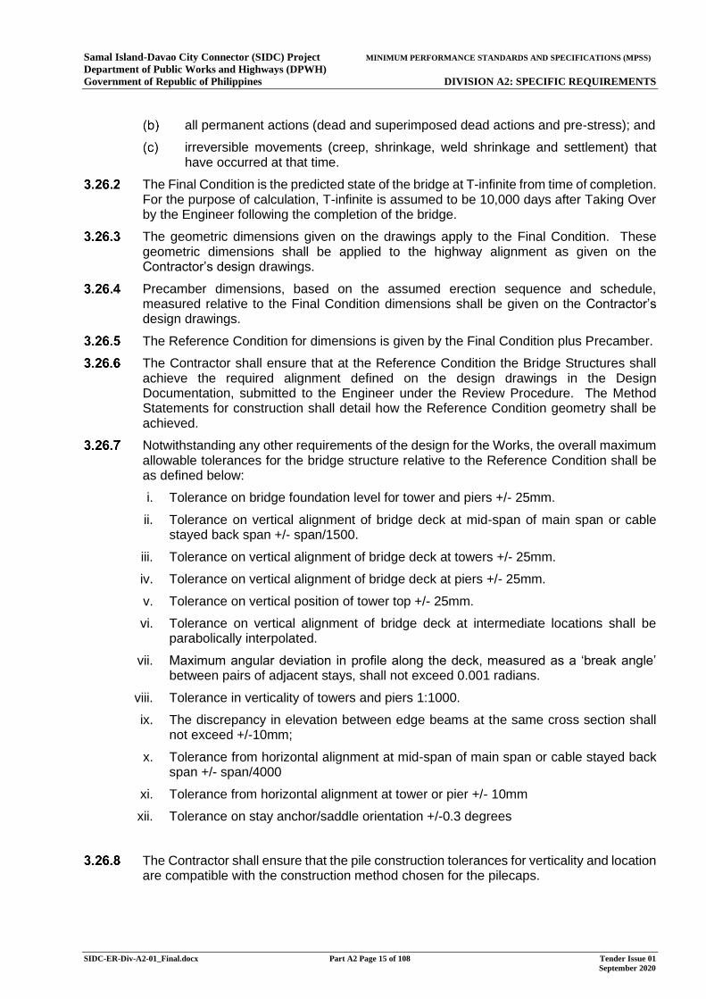
all permanent actions (dead and superimposed dead actions and pre-stress); and
irreversible movements (creep, shrinkage, weld shrinkage and settlement) that have occurred at that time.
The Final Condition is the predicted state of the bridge at T-infinite from time of completion. For the purpose of calculation, T-infinite is assumed to be 10,000 days after Taking Over by the Engineer following the completion of the bridge.
The geometric dimensions given on the drawings apply to the Final Condition. These geometric dimensions shall be applied to the highway alignment as given on the Contractor’s design drawings.
Precamber dimensions, based on the assumed erection sequence and schedule, measured relative to the Final Condition dimensions shall be given on the Contractor’s design drawings.
The Reference Condition for dimensions is given by the Final Condition plus Precamber.
The Contractor shall ensure that at the Reference Condition the Bridge Structures shall achieve the required alignment defined on the design drawings in the Design Documentation, submitted to the Engineer under the Review Procedure. The Method Statements for construction shall detail how the Reference Condition geometry shall be achieved.
Notwithstanding any other requirements of the design for the Works, the overall maximum allowable tolerances for the bridge structure relative to the Reference Condition shall be as defined below:
i. Tolerance on bridge foundation level for tower and piers +/- 25mm.
ii. Tolerance on vertical alignment of bridge deck at mid-span of main span or cable stayed back span +/- span/1500.
iii. Tolerance on vertical alignment of bridge deck at towers +/- 25mm.
iv. Tolerance on vertical alignment of bridge deck at piers +/- 25mm.
v. Tolerance on vertical position of tower top +/- 25mm.
vi. Tolerance on vertical alignment of bridge deck at intermediate locations shall be parabolically interpolated.
vii. Maximum angular deviation in profile along the deck, measured as a ‘break angle’ between pairs of adjacent stays, shall not exceed 0.001 radians.
viii. Tolerance in verticality of towers and piers 1:1000.
ix. The discrepancy in elevation between edge beams at the same cross section shall not exceed +/-10mm;
x. Tolerance from horizontal alignment at mid-span of main span or cable stayed back span +/- span/4000
xi. Tolerance from horizontal alignment at tower or pier +/- 10mm
xii. Tolerance on stay anchor/saddle orientation +/-0.3 degrees
The Contractor shall ensure that the pile construction tolerances for verticality and location are compatible with the construction method chosen for the pilecaps.
Samal Island-Davao City Connector (SIDC) Project MINIMUM PERFORMANCE STANDARDS AND SPECIFICATIONS (MPSS) Department of Public Works and Highways (DPWH) Government of Republic of Philippines DIVISION A2: SPECIFIC REQUIREMENTS
SIDC-ER-Div-A2-01_Final.docx Part A2 Page 16 of 108 Tender Issue 01 September 2020
Inspection and Maintenance Manual
Prior to the issue or deemed issue of a Taking-Over Certificate by the Engineer, the Contractor shall submit a Bridge Structures Inspection and Maintenance Manual, in accordance with these requirements.
The Bridge Structures Inspection and Maintenance Manual shall cover all elements of the Bridge Structures and all components and equipment associated with the Bridge Structures supplied under the Contract.
The Bridge Structures Inspection and Maintenance Manual shall include or make reference to all information required to inspect and maintain the Bridge Structures.
Inspection Procedures shall be included which give detailed procedures for the inspection and maintenance staff to follow when undertaking their work. As a minimum, these shall include:
health and safety considerations;
detailed procedure of inspection and maintenance operations;
equipment requirements;
access considerations;
recording and reporting procedures; and
reference documentation.
For all components with a design life less than that of the primary bridge structure elements, procedures shall include details of how the components can be replaced, including any traffic management requirements and specialist equipment required for the replacement operation.
Manufacturers’ proprietary product information shall be supplied, as well as data sheets, equipment lists and operating instructions for all components supplied.
Samal Island-Davao City Connector (SIDC) Project MINIMUM PERFORMANCE STANDARDS AND SPECIFICATIONS (MPSS) Department of Public Works and Highways (DPWH) Government of Republic of Philippines DIVISION A2: SPECIFIC REQUIREMENTS
SIDC-ER-Div-A2-01_Final.docx Part A2 Page 17 of 108 Tender Issue 01 September 2020
4 GEOTECHNICAL WORKS
Scope
The Contractor shall be responsible for carrying out design and construction of the foundations, earthworks, abutments & earth retaining structures / walls and ground improvement (if necessary) works in compliance with the Employer’s Requirements as set out in this document, the Specification, Specification appendices and on the Drawings.
Design Standard / Codes of Practice
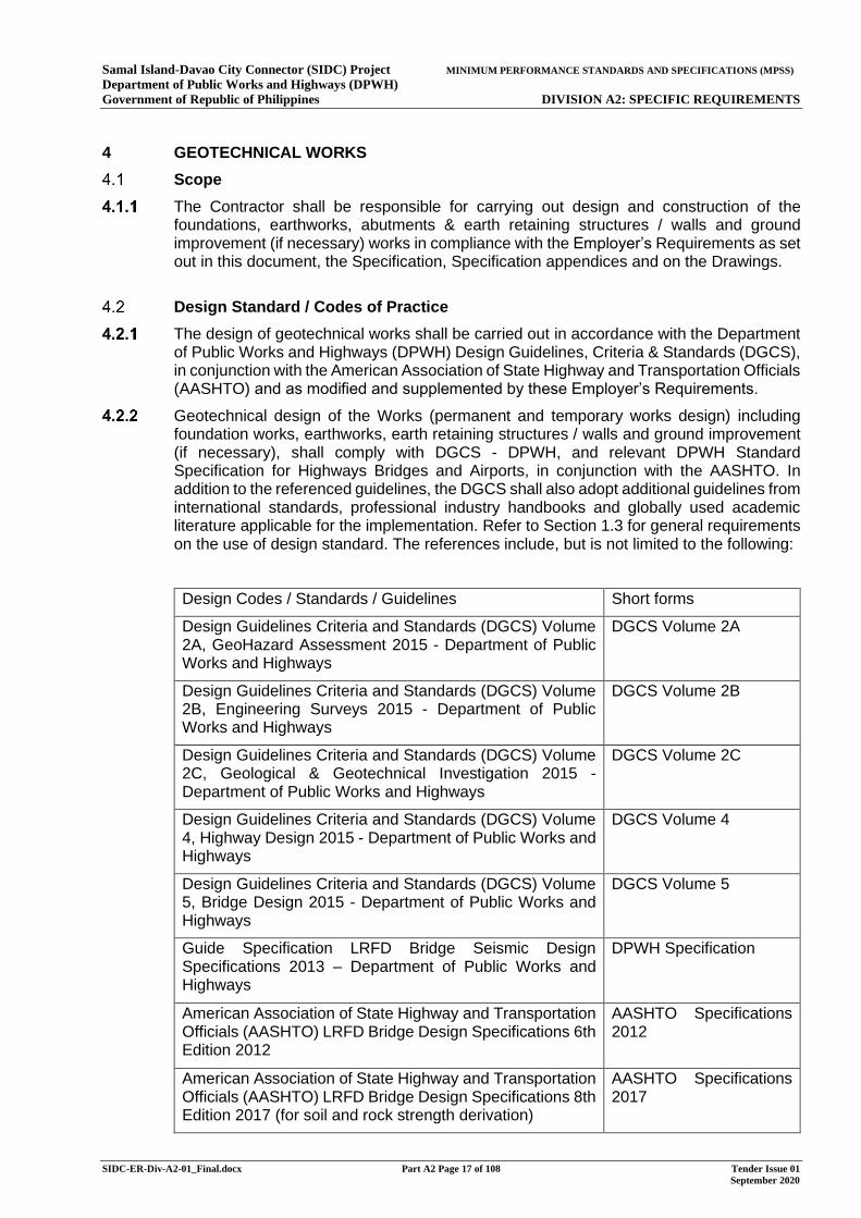
The design of geotechnical works shall be carried out in accordance with the Department of Public Works and Highways (DPWH) Design Guidelines, Criteria & Standards (DGCS), in conjunction with the American Association of State Highway and Transportation Officials (AASHTO) and as modified and supplemented by these Employer’s Requirements.
Geotechnical design of the Works (permanent and temporary works design) including foundation works, earthworks, earth retaining structures / walls and ground improvement (if necessary), shall comply with DGCS - DPWH, and relevant DPWH Standard Specification for Highways Bridges and Airports, in conjunction with the AASHTO. In addition to the referenced guidelines, the DGCS shall also adopt additional guidelines from international standards, professional industry handbooks and globally used academic literature applicable for the implementation. Refer to Section 1.3 for general requirements on the use of design standard. The references include, but is not limited to the following:
Design Codes / Standards / Guidelines Short forms
Design Guidelines Criteria and Standards (DGCS) Volume 2A, GeoHazard Assessment 2015 - Department of Public Works and Highways
DGCS Volume 2A
Design Guidelines Criteria and Standards (DGCS) Volume 2B, Engineering Surveys 2015 - Department of Public Works and Highways
DGCS Volume 2B
Design Guidelines Criteria and Standards (DGCS) Volume 2C, Geological & Geotechnical Investigation 2015 - Department of Public Works and Highways
DGCS Volume 2C
Design Guidelines Criteria and Standards (DGCS) Volume 4, Highway Design 2015 - Department of Public Works and Highways
DGCS Volume 4
Design Guidelines Criteria and Standards (DGCS) Volume 5, Bridge Design 2015 - Department of Public Works and Highways
DGCS Volume 5
Guide Specification LRFD Bridge Seismic Design Specifications 2013 – Department of Public Works and Highways
DPWH Specification
American Association of State Highway and Transportation Officials (AASHTO) LRFD Bridge Design Specifications 6th Edition 2012
AASHTO Specifications 2012
American Association of State Highway and Transportation Officials (AASHTO) LRFD Bridge Design Specifications 8th Edition 2017 (for soil and rock strength derivation)
AASHTO Specifications 2017
Samal Island-Davao City Connector (SIDC) Project MINIMUM PERFORMANCE STANDARDS AND SPECIFICATIONS (MPSS) Department of Public Works and Highways (DPWH) Government of Republic of Philippines DIVISION A2: SPECIFIC REQUIREMENTS
SIDC-ER-Div-A2-01_Final.docx Part A2 Page 18 of 108 Tender Issue 01 September 2020
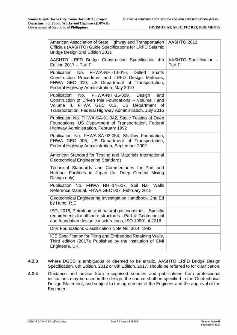
American Association of State Highway and Transportation Officials (AASHTO) Guide Specifications for LRFD Seismic Bridge Design 2nd Edition 2011
AASHTO 2011
AASHTO LRFD Bridge Construction Specification 4th Edition 2017 – Part F
AASHTO Specification – Part F
Publication No. FHWA-NHI-10-016, Drilled Shafts Construction Procedures and LRFD Design Methods, FHWA GEC 010, US Department of Transportation, Federal Highway Administration, May 2010
Publication No. FHWA-NHI-16-009, Design and Construction of Driven Pile Foundations – Volume I and Volume II, FHWA GEC 012, US Department of Transportation, Federal Highway Administration, July 2016
Publication No. FHWA-SA-91-042, Static Testing of Deep Foundations, US Department of Transportation, Federal Highway Administration, February 1992
Publication No. FHWA-SA-02-054, Shallow Foundation, FHWA GEC 006, US Department of Transportation, Federal Highway Administration, September 2002
American Standard for Testing and Materials International Geotechnical Engineering Standards
Technical Standards and Commentaries for Port and Harbour Facilities in Japan (for Deep Cement Mixing Design only)
Publication No. FHWA NHI-14-007, Soil Nail Walls Reference Manual, FHWA GEC 007, February 2015
Geotechnical Engineering Investigation Handbook, 2nd Ed by Hung, R.E
ISO, 2016, Petroleum and natural gas industries - Specific requirements for offshore structures - Part 4: Geotechnical and foundation design considerations, ISO 19901-4:2016
DnV Foundations Classification Note No. 30.4, 1992
ICE Specification for Piling and Embedded Retaining Walls, Third edition (2017); Published by the Institution of Civil Engineers, UK.
Where DGCS is ambiguous or deemed to be erratic, AASHTO LRFD Bridge Design Specification, 6th Edition, 2012 or 8th Edition, 2017, should be referred to for clarification.
Guidance and advice from recognised sources and publications from professional institutions may be used in the design, the source shall be specified in the Geotechnical Design Statement, and subject to the agreement of the Engineer and the approval of the Engineer.
Samal Island-Davao City Connector (SIDC) Project MINIMUM PERFORMANCE STANDARDS AND SPECIFICATIONS (MPSS) Department of Public Works and Highways (DPWH) Government of Republic of Philippines DIVISION A2: SPECIFIC REQUIREMENTS
SIDC-ER-Div-A2-01_Final.docx Part A2 Page 19 of 108 Tender Issue 01 September 2020
General Requirements
The Contractor shall engage professional consultants to provide all professional design and engineering discipline skills required to complete the investigation, design and documentation work necessary for a well-considered design.
The Contractor shall construct the Works in accordance with the approved design, in a manner and with the materials as specified in the approved design and reviewed without comment by the Employer and the Engineer.
All ground investigation works shall be carried out in accordance with DGCS Volume 2C, DGCS Volume 4, DGCS Volume 5 and the Ground Investigation Specification in Annex D of the Employer’s Requirements.
All foundations design shall be carried out in accordance with DGCS Volume 5 Section 10 and 15.
All abutments and walls design shall be carried out in accordance with DGCS Volume 5 Section 16.
All earthworks shall be carried out in accordance with DGCS Volume 4 Section 8.
All deep foundation works shall be constructed in accordance with the Specification Part F.
All shallow foundation works shall be constructed in accordance with the Part C of the Specification.
All earthworks shall be constructed in accordance with the Part C of the Specification.
Ground investigation works shall be carried out in accordance with the Ground Investigation Specification and the Employer’s Requirements.
Preliminary pile and production piles (also known as working piles), load testing shall be constructed and carried out in accordance with the Part F of the Specification and the relevant ASTM standards.
Plate loading test for shallow foundation shall be constructed and carried out in accordance with relevant ASTM standards.
The Works shall be designed and constructed using proven up-to-date technology and comply with codes of practice and design standards applicable to the Works. The Contractor’s proposal shall in any case, subject to the Engineer’s opinion and the Engineer’s approval, not be less than or inferior to those described in the Engineer’s Requirements.
All geotechnical design shall be based on full analysis of the sub-soil condition, using suitably logged borehole, in-situ and / or laboratory test data and geophysical or other assessment methods.
All geotechnical design shall take into account the ground conditions or presence of adverse geological features, such as fault zones, cavities, where applicable.
All geotechnical design shall take into account the presence of existing structures, utilities, and the presence of known potential underground obstructions. In particular, the Contractor shall take into account the presence of abandoned borehole casing and drilling rods from the Feasibility Study Stage Ground Investigation Works. Details of known potential obstructions are provided in the Ground Investigation and Geophysical Survey Reports provided as Site Data in the Bid Library. The Contractor shall take all reasonably practicable measures to identify any other potential underground obstructions and consider them in the geotechnical design.
Samal Island-Davao City Connector (SIDC) Project MINIMUM PERFORMANCE STANDARDS AND SPECIFICATIONS (MPSS) Department of Public Works and Highways (DPWH) Government of Republic of Philippines DIVISION A2: SPECIFIC REQUIREMENTS
SIDC-ER-Div-A2-01_Final.docx Part A2 Page 20 of 108 Tender Issue 01 September 2020
Blasting, the use of rapid expansion techniques and chemical non-explosive rock splitting agents are not permitted in this Contract.
The design of all geotechnical works shall minimize the disturbance to the existing seawalls, revetment or other coastal protection features, if any, along the coastline of Samal Island and Davao City. The Contractor shall liaise with relevant authorities and parties for the Bridge Structures, foundations works, and Temporary Works in order to minimise impact on existing seawalls, revetment or other coastal protection features. If affected by the Works, these shall be designed and reinstated to be the same as the existing as-built layout and requirements. The design shall be submitted for review in accordance with the Review Procedure before commencement of any reinstatement works. If modification to existing edge structures is unavoidable, the Contractor shall design and construct the required modification works subject to the agreement of the Engineer and approval of the Engineer and the relevant authorities.
The performance of existing seawalls, revetment and other coastal protection features shall not be affected by the proposed viaducts and the associated foundation works after completion. In particular, the Works shall be designed to prevent any structural effects including but not limited to loading, deflection, settlement of the viaduct piers/foundation affecting the existing seawall, revetment and other coastal protection features.
The Contractor shall carry out a risk assessment as part of the earthworks, foundation works, abutments and earth retaining structures / walls design in order to minimise any risk to the general public, pedestrians, cyclists and any other road users resulting from the design, execution and completion of the Works.
The Contractor shall take all necessary measures to obviate any adverse effects on the surrounding area and to prevent flooding or pollution.
Gabions and crib walling shall not be permitted in any part of the design of the Works. Any proposals for necessary works to existing gabions or crib walling shall be submitted to the Engineer for review and the Engineer for approval in accordance with the Review Procedure.
The Contractor shall keep excavations for earthworks and structures free from groundwater and surface water and undertake every reasonable means to ensure that formation is protected from inclement weather. The Contractor shall remove and replace all materials damaged by water or trafficking at formation level with well compacted suitable granular fill or mass concrete fill prior to upfilling or before foundation construction.
Certificates shall be provided by the Contractor to confirm that any geosynthetics / geotextiles used in the Earthworks shall have a minimum operational life span of 120 years.
The Contractor shall ensure the stability of sections of live carriageway, footpath, pipeline, structures, buildings and the like adjacent to any temporary slopes. The Contractor shall demonstrate stability of live sections of carriageway, footpath, pipeline, structures, buildings and the like for the duration of any adjacent temporary slopes by means of appropriate surface movement monitoring.
The Contractor shall take the full responsibility for liaison and coordination with the Engineer, the Employer and the relevant authorities at every stage of the design development process.
Notwithstanding the other requirements of the Contract, the Contractor shall comply with the requirements in the Environmental Compliance Certificate (ECC) in relation to all geotechnical works. Refer to Annex A5 of the Employer’s Requirement Division A1. In particular, the Contractor shall take cognisance of the following:
Samal Island-Davao City Connector (SIDC) Project MINIMUM PERFORMANCE STANDARDS AND SPECIFICATIONS (MPSS) Department of Public Works and Highways (DPWH) Government of Republic of Philippines DIVISION A2: SPECIFIC REQUIREMENTS
SIDC-ER-Div-A2-01_Final.docx Part A2 Page 21 of 108 Tender Issue 01 September 2020
collection and appropriate disposal of excavated spoil;
application for consents from relevant authorities for the use of drilling fluids other than water;
and limits on noise and vibrations
Construction and Demolition Materials (C&D Materials)
4.3.28.1 The amount of marine sediments excavated from the Works shall be minimised as far as practicable e.g. from the excavation of the foundation and associated substructures.
4.3.28.2 The Contractor shall take all necessary measures to minimise the dredging/excavation of marine sediment. In the event that dredging/excavation of marine sediment is unavoidable, the Contractor shall handle/process such marine sediment in accordance with the procedures given in EMP and ECC. The Contractor shall be responsible for obtaining all necessary approvals and permits where relevant. Where the dredging is outside the Site covered by the ECC, the Contractor shall follow the relevant legislation pertaining to environmental requirements in the Philippines. Refer to Annex A5 of the Employer’s Requirements for details. If he proposes off-site disposal of any amount of the marine sediment, the Contractor shall only dispose of the marine sediment in accordance with the requirements in the ECC.
Existing and Proposed Geotechnical Features
4.3.29.1 The Contractor shall be responsible for the review and assessment of the stability of any existing geotechnical features in the vicinity of the Works that will affect / will be affected by the Works and seek comments and / or approval from affected parties.
4.3.29.2 The Contractor shall review and carry out a detailed investigation and assessment of the stability and serviceability conditions of all existing features / structures that will affect / will be affected by the Works.
Underground Utilities
4.3.30.1 Prior to commencing, piling and excavation operations, the Contractor shall take all reasonably practicable measures to identify all utilities, buried or otherwise, in the vicinity of the piling and excavation works. A pre-condition survey shall be carried out on identified structures and utilities. One copy of the pre-condition survey shall be submitted to the Engineer and Employer for record prior to detailed design.
4.3.30.2 Should existing utilities be identified in the vicinity of the piling works, the Contractor shall propose monitoring plans, including monitoring instrumentation, measurement frequencies and trigger levels, for the Engineer’s agreement. The limits on vibration at adjacent properties and structures shall be proposed by the Contractor for the Engineer, Employers’ and the utilities owners’ agreement.
4.3.30.3 The Contractor shall undertake all works necessary in advance of geotechnical works to ensure that no damage is caused to adjacent structures or utilities. All damage caused to adjacent structures or utilities by geotechnical works shall be made good by the Contractor and the cost shall be borne by the Contractor.
4.3.30.4 Special attention shall be given to avoid affecting the existing underground utilities inside and in vicinity of the works areas. A survey shall be carried out by the Contractor to locate all of these underground utilities as soon as practicable after the Commencement Date
Samal Island-Davao City Connector (SIDC) Project MINIMUM PERFORMANCE STANDARDS AND SPECIFICATIONS (MPSS) Department of Public Works and Highways (DPWH) Government of Republic of Philippines DIVISION A2: SPECIFIC REQUIREMENTS
SIDC-ER-Div-A2-01_Final.docx Part A2 Page 22 of 108 Tender Issue 01 September 2020
and access to the Site is available to facilitate monitoring. Any monitoring or protection works for the underground utilities required in connection with the execution of the Works shall be deemed to be part of the Works under this Contract. The design and construction of the Bridge Structures and associated foundations shall cater for and avoid conflict with the existing underground utilities unless prior agreement and approval is granted from the Engineer and the underground utilities’ owner. Where diversion of utilities is required, the Contractor shall be responsible to liaise with the relevant authorities, and to design and execute the diversion accordingly.
4.3.30.5 The Contractor shall be responsible for locating and protecting any utilities on Site and safeguarding by all necessary means for any wires, cables, pipes, mains or other utilities encountered within the Site. The Contractor shall locate underground utilities by cable detector first and then by hand dug inspection pits prior to any excavation. The Contractor shall submit a contingency plan and shall be responsible for making good any damage to existing utilities caused by the Works. The Contractor shall make good such damage within 24 hours of the incident. For any damage not rectified within 24 hours, the Engineer may arrange for other contractors to carry out the repair. For critical utilities such as communication cables and power cables, the Engineer may arrange its maintenance contractor to carry out immediate repairs. The Engineer shall be entitled to recover costs from the Contractor for carrying out the works in accordance with Conditions of Contract Sub-Clause 7.6 – Remedial Works.
4.3.30.6 The identification of underground utilities shall be considered and reported in the Preliminary Design Report, Detailed Engineering Design Report and Geotechnical Design Report.
Geotechnical Instrumentation & Monitoring
4.3.31.1 The Contractor shall propose instrumentation and monitoring to monitor the effects of his work to the adjacent structures and utilities. The guideline for the geotechnical instrumentation shall refer to DPWH Volume 2C Section 12.
4.3.31.2 The instrumentation and monitoring proposal shall be submitted to the Engineer for review and the Engineer for approval prior to the commencement of work.
4.3.31.3 The Contractor shall propose the type, location, monitoring frequency and the allowable limits of each of instrumentation and monitoring and the purpose of each type of instrumentation.
4.3.31.4 Method statement and typical details shall be submitted to the Engineer for review and the Engineer for approval prior to installation.
4.3.31.5 The Contractor shall take all necessary precautions to protect the instruments and maintain the instruments in good working order after installation and commissioning. For all instruments which project through and above ground level, special precautions shall be taken to provide protection from vehicles and plant, including substantial and readily visible barriers at a distance of 750mm around each instrument, or as agreed with the Engineer. Heavy compaction equipment shall not approach within 1.5m of projecting instruments, or as otherwise required to avoid damage. Damaged instruments shall be replaced or repaired by the Contractor within seven days of the date at which the damage occurred.
4.3.31.6 All instruments shall be labelled with their reference number at the location where the readings or measurements are taken. The labelling shall be permanent, using methods or materials to be proposed by the Contractor and agreed with the Engineer.
4.3.31.7 The format of the instrumentation records shall be proposed by the Contractor and agreed by the Engineer.
Samal Island-Davao City Connector (SIDC) Project MINIMUM PERFORMANCE STANDARDS AND SPECIFICATIONS (MPSS) Department of Public Works and Highways (DPWH) Government of Republic of Philippines DIVISION A2: SPECIFIC REQUIREMENTS
SIDC-ER-Div-A2-01_Final.docx Part A2 Page 23 of 108 Tender Issue 01 September 2020
4.3.31.8 All records produced for the instrumentation must include the following data:
Project name.
Contract name and number.
Instrument reference number and type
Dates of installation, reading or summary.
Times of installation or reading.
Chainage and offset (or co-ordinates if appropriate)
Personnel responsible.
Relevant comments or remarks
4.3.31.9 For instruments measure movements, the accuracy of level readings, shall be measured to an accuracy of +/- 2mm.
4.3.31.10 After installation the functioning and monitoring of each instrument shall be demonstrated to the Engineer including the recording of measured values using the appropriate readout device. As part of the commissioning three sets of readings shall be taken and compared. When instruments are installed before earthworks start, then these three sets of readings shall also be taken before the earthworks start. If there are significant differences or anomalies, then further readings shall be taken. Once two sets of comparable reading have been taken, these shall be averaged to form the base readings, representing conditions before the start of earthworks.
Geotechnical Submissions
Contractor shall submit the following documents in accordance with the Review Procedure in Employer’s Requirements Division A1 General Requirements:
Preliminary Desk Study
Scope and Specifications for proposed geotechnical investigations
Factual report from Geotechnical investigations
Geotechnical Design Statement
Ground Investigation Report (GIR)
Geotechnical Design Report (GDR)
Seismic Study Report including review of seismic hazard, local site soil conditions and their effect on seismic action, and earthquake-induced hazards including but not limited to liquefaction
Geotechnical Feedback Report
Inspection Test Plans for geotechnical works
Method Statements for geotechnical works
Specifications for proposed caisson foundation and ground improvement if any
Ground Condition Information
For information regarding the ground conditions, refer to the geotechnical reports under Site Data.
Samal Island-Davao City Connector (SIDC) Project MINIMUM PERFORMANCE STANDARDS AND SPECIFICATIONS (MPSS) Department of Public Works and Highways (DPWH) Government of Republic of Philippines DIVISION A2: SPECIFIC REQUIREMENTS
SIDC-ER-Div-A2-01_Final.docx Part A2 Page 24 of 108 Tender Issue 01 September 2020
Ground Investigation (GI)
A desk study to identify existing records has been undertaken and ground investigation has been undertaken as part of the pre-tender development of the project. Borehole logs, laboratory test results, reports and other information are provided in the Site Data.
The Contractor shall review and update any relevant geological information including but not limited to the following items as part of the design of the geotechnical works for the project:
Reports on previous studies
Relevant past site investigation records, geotechnical design reports, and construction records,
Published geological maps and memoirs
Relevant topographical maps
Relevant bathymetrical maps
Relevant services and utilities records
The Contractor shall review the available Ground Investigation (GI) information and undertake all necessary ground investigation works together with the necessary topographical and bathymetric surveys to substantiate all geological models and geotechnical parameters adopted in the design. Where appropriate or when considered necessary, the Contractor shall carry out additional boreholes, geophysics, laboratory or field tests at his own expense to verify the design parameters. The ground investigation works reporting and the minimum scope of ground investigation to be carried out by the Contractors shall be based on the requirements in DGCS Volume 2C, DGCS Volume 4, Article 2.3, DGCS Volume 5 Article 5.1.2, Sections 4.7.2.2, 4.7.3.9, 4.8.1, 4.10.1, 4.13.2 of this Division A2 of the Employer’s Requirements, the requirements in the Annex D - Ground Investigation Specification of DPWH Specification in the Employer’s Requirements and relevant ASTM Standards.
The Contractor shall submit the Ground Investigation Strategy Document to the Engineer's review in accordance with the Review Procedure and record in accordance with the Review Procedure. The proposal shall also cover the location of the ground investigation, frequency and type of sampling and in-situ testing and laboratory test to be carried out for design purposes and verification of design purposes.
The location(s) of the boreholes shall be symmetrically centred on the centre of the pier locations such at the variability of the ground conditions can be best defined. The ground model obtained from locations shall include observations from other all locations to help define variability.
The depth of all boreholes shall be no less than 1 times the largest horizontal dimension of the pier/pylon foundation spread foundation or pile cap below the deepest part of the foundation (e.g. below the base of the ground improved zone or below the base of the deepest pile).
All boreholes shall be carried out in the optimum manner to obtain the best quality samples, this will include piston sampling in soft layers to 100mm wireline triple core tube drilling in rock for example. An adequate number of samples shall be recovered for:
Accurate logging of the soil strata
Supply of samples for laboratory testing (with contingency in case of sample disturbance)
Samal Island-Davao City Connector (SIDC) Project MINIMUM PERFORMANCE STANDARDS AND SPECIFICATIONS (MPSS) Department of Public Works and Highways (DPWH) Government of Republic of Philippines DIVISION A2: SPECIFIC REQUIREMENTS
SIDC-ER-Div-A2-01_Final.docx Part A2 Page 25 of 108 Tender Issue 01 September 2020
The implementation of the works shall be such that optimum recovery and sample quality is achieved in any type of ground condition.
In-situ testing shall be carried out appropriate to the design intent, this may include:
SPTs in soil strata
Downhole CPTs in soil strata carried out in boring parallel to the sample recovery hole
Pressuremeter / high pressure dilatometer in all strata as appropriate
Laboratory testing shall be carried out on suitable quality samples (the samples to be inspected for disturbance) to quantify:
Index properties
Chemical properties for structural design
Strength and stiffness properties required for the design
Validation testing for ground improvement works
As above, specific testing shall be implemented in the case that specialist geotechnical works are proposed (e.g. soil improvement techniques). In such situations, additional boreholes / CPTs are likely to be required adequately characterise the sediment and to provide adequate samples to allow the ground improvements design to be carried out.
There results of the investigation shall be presented in a Factual report and the includes with all other data in the design reports.
The Ground Investigation Strategy Document shall include but not be limited to the following:
The scope of the investigations,
a summary of existing investigation data, a gap analysis (of which the above is the minimum requirement) and a summary specification,
A description of the proposed GI, including justification for the number, location, and types of exploratory boreholes and / or trial pits,
A plan showing the location of all proposed exploratory borehole locations and / or trial pits and proposed termination depths,
A description of the proposed sampling strategy including type and frequency
The number and type of proposed in-situ and laboratory tests
The technical requirements for ground investigation shall be in accordance with the requirements in the Annex D - Ground Investigation Specification in the Employer’s Requirements.
The Contractor shall submit an example set of AGS data in the required format for the approval of the Engineer 14 days prior to the commencement of the drilling works. The sample data set shall contain all relevant groups and hole types. On request, the Contractor shall provide to the Engineer copies of project files, graphics template files, library files, AGS import and export files being used with the relevant geotechnical application software for the production of logs, diagrams and the AGS format data file.
Further to the requirements of Ground Investigation Specification in Annex D of the Employer’s Requirements Division A2, core boxes shall be 1.05m in length, 0.45m in width and able to store at least 4m of core samples. All recovered cores shall be photographed in accordance with the requirements of Clause 4.14 of the Ground Investigation Specification. Where core is lost or sub-samples for testing are removed, these locations
Samal Island-Davao City Connector (SIDC) Project MINIMUM PERFORMANCE STANDARDS AND SPECIFICATIONS (MPSS) Department of Public Works and Highways (DPWH) Government of Republic of Philippines DIVISION A2: SPECIFIC REQUIREMENTS
SIDC-ER-Div-A2-01_Final.docx Part A2 Page 26 of 108 Tender Issue 01 September 2020
shall be clearly marked out with the actual dimensions in the core box such every 1.05m of core box represents 1m of core. Minimum core diameter shall be 100mm
The Contractor shall provide storage space for all core boxes and samples recovered for the Contract. The storage space shall be made of standard 20’ containers or equivalent and with the necessary conversion for the access of Contractor’s personnel for retrieving selected items as requested by the Engineer. The Contractor shall submit his proposal of the storage arrangement for the Engineer’s approval. Alternative means of storage space arrangement that is suitable to the Contractor’s site arrangement may be considered and shall be subject to the Engineer’s approval.
The Contractor shall store the core boxes and samples recovered in this Contract in the storage space as soon as the necessary inspection and logging works have been completed and as agreed by the Engineer, in order to avoid those items from excessive exposure to sunlight and moisture. Upon the Engineer or the Engineer’s request, the Contractor shall, within 3 days, retrieve the selected items from the storage and lay them out at an accessible location as agreed by the Engineer or the Engineer for his easy inspection.
Pile Foundation Works
General
4.7.1.1 Piling shall be designed in accordance with the standards and design guidance listed in Section 4.2 of this Division A2 of the Employer’s Requirements.
4.7.1.2 The design and construction of any pile type proposed by the Contractor shall comply with the minimum requirements specified and the philosophy described in Employer’s Requirements unless otherwise agreed by the Engineer and approved by the Engineer.
4.7.1.3 The Contractor shall not be permitted to leave permanent voids created during construction in the land and marine foundations. All voids shall be infilled with mass concrete.
4.7.1.4 The Contractor shall ensure the stability of the bored hole and temporary liner if used, during piling construction. The Contractor shall specify in the piling Method Statement the proposed method for supporting the excavation. In case the Contractor intends to use fluid as mean of supporting the excavation, the requirements for use of support fluid shall be as stated in Part F of the Specification.
4.7.1.5 When temporary casing is used to ensure the stability of the bore hole during excavation, the Contractor shall propose a toe level of the temporary casing to ensure that no soil ingress occurs during the excavation, for the Engineer’s review.
4.7.1.6 Considering the nature of encountering cavities and fractured rocks, the Contractor shall ensure the integrity of the bore hole during excavation, especially below the shallow layer of competent rock. The Contractor shall propose the measures for bore hole stability and submit the detail to the Engineer for review.
4.7.1.7 Permanent casing shall be used for piles constructed over water. The design of the permanent casing shall consider the loads during construction stage and/or temporary case. No plastic hinge shall be allowed to be formed in the permanent casing during construction stage and/or temporary case. The requirements for permanent casing are given in the Specification Part F Section 5.4.13. Permanent casing shall not be used as a structural element as part of the permanent structure.
4.7.1.8 When steel piles are used as the foundation for temporary construction platforms such as trestles, the Contractor shall consider the durability of the steel pile, including the effects from wave action, salinity environment and growth of marine organisms and the design
Samal Island-Davao City Connector (SIDC) Project MINIMUM PERFORMANCE STANDARDS AND SPECIFICATIONS (MPSS) Department of Public Works and Highways (DPWH) Government of Republic of Philippines DIVISION A2: SPECIFIC REQUIREMENTS
SIDC-ER-Div-A2-01_Final.docx Part A2 Page 27 of 108 Tender Issue 01 September 2020
lifetime. Refer to the Structural Design Basis for further details of the corrosion protection requirements.
4.7.1.9 For major temporary works, such as trestle or piling platform, the Contractor shall propose site testing to ensure the constructability, workmanship, stability and capacity of the temporary works. This shall be included in the temporary works design submission.
4.7.1.10 The Contractor shall be fully responsible for the integrity and the performance of the production piles (working piles) for the loads defined in his design.
4.7.1.11 The design of the permanent piles shall be verified and confirmed through the construction and testing of the preliminary piles. The design of the working piles shall be reviewed and may be revised subject to the findings of testing of the preliminary piles. The Contractor shall carry out a design review for the piling design based on the results from the preliminary piles test and predrills (construction stage ground investigation for particular geotechnical works) for the working piles. A design review report and the finalized design of working piles with full details included in the revised Design Documentation shall be re-submitted to the Engineer’s review and Employer’s approval in accordance with the Review Procedure prior to the construction of working piles.
4.7.1.12 Ground Investigation techniques for design of piles shall consider the design methodology when specifying tests. For pile design in rock the following shall be considered when specifying in-situ and laboratory testing:
GSI
Rock Mass modulus especially perpendicular to pile sides
USC
Saw cut coefficient of friction.
4.7.1.13 Records
One copy of the piling records, compiled in accordance with Table 5.1 in Section 5 of the Specification Part F, shall be supplied to the Engineer within 24 hours of the completion of each individual pile.
Records of material testing shall be undertaken in accordance with the Specification Part F and submitted to the Engineer.
Method Statement for Drilled Shafts
4.7.2.1 Unless otherwise agreed with the Engineer in accordance with the Review Procedure prior to the commencement of the piling works, the Contractor shall supply all relevant details regarding the proposed method of piling, plant, monitoring equipment and risk assessment to the Engineer for review and in accordance with the agreed Contractor’s programme. The Contractor's Method Statement shall include, as a minimum, those items listed below, as appropriate:
Site staff and organisation;
the experience of the Contractor and his staff with the piling type and particular ground conditions;
the details of the piling plant, which should be sufficient to demonstrate its suitability for achieving the required penetration and to work within any noise and vibration limits;
the sequence and timing of piling, with regard to not adversely affecting adjacent piles;
Samal Island-Davao City Connector (SIDC) Project MINIMUM PERFORMANCE STANDARDS AND SPECIFICATIONS (MPSS) Department of Public Works and Highways (DPWH) Government of Republic of Philippines DIVISION A2: SPECIFIC REQUIREMENTS
SIDC-ER-Div-A2-01_Final.docx Part A2 Page 28 of 108 Tender Issue 01 September 2020
inspection test plan as per the Specification Part F Article 5.4.15
setting out and means of achieving specified tolerances;
the time period for boring and concreting which may influence the design assumptions for pile resistance that can be mobilised;
the length of temporary / permanent casing or use of support fluids to maintain adequate support to the ground during construction;
the method and equipment for cleaning or forming the base of the pile where end bearing is assumed in the design. The design assumptions for end bearing should take into account what can be realistically achieved with the proposed method;
the method for verifying shaft and base cleanliness
the method for cleaning the shaft of the pile prior to placement of the reinforcement cage and concrete pour;
the methods that will be used to check the pile depth, bore stability, base cleanliness and compliance with the specified tolerances;
the method of placing concrete to ensure it is placed vertically down the bore; where concrete is placed under water or support fluid the method of placing concrete by tremie should be described;
the frequency and means of testing concrete consistence, strength class and compliance values for grouts;
the means of placing concrete, installation of reinforcement including the lapping of reinforcement cages, the method of maintaining concrete cover and the vertical position of the cage and any additional reinforcement for lifting, handling and placing;
details of permanent casings and how they are to be maintained during concreting;
details of measures that will be taken to minimise disturbance of the surrounding ground;
the level to which concrete will be cast and details of how completed piles are to be protected from possible subsequent damage;
procedures for dealing with emergencies such as loss of support fluid, obstructions and piles that are out of tolerance;
typical record sheets;
details of sonic logging;
details of koden test;
details of maintained load test for preliminary piles and working piles
details of interface coring
details of full depth concrete coring
details of method to deal with cavities prior to concreting or excessive consumption of concrete during concreting due to presence of cavities
details of probe holes if any
details of pressure grouting of cavities if any
4.7.2.2 Construction Stage Boreholes (Predrills) Prior to Piling Works
Samal Island-Davao City Connector (SIDC) Project MINIMUM PERFORMANCE STANDARDS AND SPECIFICATIONS (MPSS) Department of Public Works and Highways (DPWH) Government of Republic of Philippines DIVISION A2: SPECIFIC REQUIREMENTS
SIDC-ER-Div-A2-01_Final.docx Part A2 Page 29 of 108 Tender Issue 01 September 2020
The Contractor shall construct ground investigation boreholes (predrills) prior to the pile foundation construction works. The Contractor shall propose the sampling, in-situ testing and laboratory testing for the predrills in order to verify the geological condition and enable suitable modification, if necessary, to the pile design to suit the actual ground condition.
The minimum number of predrill for shall be in accordance with the requirements stated in Table 10.4.2-1 in ASSHTO 2017 (8th edition). All predrills shall be sunk within the pile footprint as far as practicable.
The predrills shall be terminated at a level which shall satisfy all the requirements stated in DGCS Volume 5 Table 15.1.2-1 for Deep Foundations, unless otherwise proposed by the Contractor and agreed by the Engineer. The phrase “a minimum or 3000mm of rock core” in DGCS Volume 5 Table 15.1.2-1 for Deep Foundations shall be replaced by “a minimum or 10m into limestone with total core recovery equal to or more than 85% or 5m into non-calcareous rock with total core recovery equal to or more than 85%”.
The Contractor shall inform the Engineer on the details of drilling status, including the ground material that has been encountered during drilling and when the drilling reaches tentative pile toe level.
The Contractor shall review the pile design based on the location and size of the cavities encountered based on the predrills for the same pile group.
Predrills shall be completed for all piles within the same pile group prior to commencement of the pile construction in the said pile group.
Preliminary Pile Test(s)
4.7.3.1 The Contractor shall consider the ground conditions at each piling location and develop proposals for piling systems suitable to install the piles within the given ground conditions. Consideration shall be given to preliminary trial bores to test the method of construction. Detailed method statements shall be prepared and submitted to the Engineer for review and the Engineer for approval in accordance with the Review Procedures.
4.7.3.2 Trials for the drivability of the permanent steel casing is required. The type, extent and frequency of the site trials shall be specified by the Contractor for the Engineer’s review and Engineer’s approval in accordance with the Review Procedures.
4.7.3.3 The trials shall be conducted using the same methods proposed for construction, in similar ground conditions at the relevant pile foundation locations. The site trials shall include appropriate methods to confirm the results achieved.
4.7.3.4 The design of the piles shall be verified and confirmed through the construction and testing of the preliminary piles. The Contractor shall submit his proposal of preliminary pile construction and testing in accordance with the requirements specified in the construction specification Part F Section 4.17 and 5.4.18 of the Specification and submitted to the Engineer and Employer in accordance with the Review Procedure prior to construction.
4.7.3.5 The Contractor shall carry out the testing of preliminary piles in accordance with the requirements specified in the construction specification Part F Section 5.4.12 of the Specification and other relevant requirements in the Contract.
4.7.3.6 The Contractor shall develop a preliminary pile construction and test proposal with full details and submit it to the Engineer in accordance with the Review Procedure prior to construction. The proposal shall include the following:
Samal Island-Davao City Connector (SIDC) Project MINIMUM PERFORMANCE STANDARDS AND SPECIFICATIONS (MPSS) Department of Public Works and Highways (DPWH) Government of Republic of Philippines DIVISION A2: SPECIFIC REQUIREMENTS
SIDC-ER-Div-A2-01_Final.docx Part A2 Page 30 of 108 Tender Issue 01 September 2020
The size, depth of the preliminary pile, considering the supporting structure type, loading, pile size and pile founding criteria of the working piles.
The location of the proposed borehole location for each preliminary pile, the termination criteria, sampling type & frequency, type and frequency of the in-situ testing and laboratory testing. The minimum requirements for the borehole for the preliminary pile are given in the construction specifications Part F Section 5.4.18 of the Specification.
Adequate geotechnical data shall be obtained to ensure that the results from the preliminary pile, through the pile design method can be applied to the working piles taking full account of the following:
(i) Variations in ground properties
(ii) Variations in pile dimensions
(iii) Variations in pile construction times (ideally the pile construction times shall be the same in the preliminary and working piles)
(iv) Variations in any pile construction methodology (ideally the pile construction methodology shall be the same in the preliminary and working piles)
(v) Variations in load application between working piles and preliminary piles (Specifically in the context of O-Cell testing if proposed).
(vi) For design of working piles in tension, tension load tests shall be required.
The instrumentation for the preliminary pile which shall be fully instrumented. The minimum requirements for the instrumentation for the preliminary pile are given in the construction specification Part F Section 5.4.18.5 of the Specification.
The applicable extent of each preliminary pile, considering similar loading & ground conditions and pile founding criteria for the working piles
4.7.3.7 Not used.
4.7.3.8 Scaling of pile diameter between working piles and preliminary piles is not allowed. The proposed length of the preliminary piles shall be provided in the design drawings.
4.7.3.9 A minimum of 1 no. of borehole shall be sunk within the preliminary pile footprint as far as practicable prior to the installation. The requirements in DGCS Volume 2C, the construction specification Part F Section 5.4.18 of the Specification and Section 4.7.2.2 (a) & (b) of this Division A2 in the Employer’s Requirements.
4.7.3.10 Upon completion of the borehole of the preliminary pile, the pile toe level shall be reviewed based on the predrill results by the Contractor and submitted to the Engineer for review and the Engineer for approval in accordance with the Review Procedure.
4.7.3.11 Working piles shall not be used as part of the reaction pile system or supporting system for any pile load tests.
4.7.3.12 Koden test or similar, cross-holes sonic logging test, static load test, interface coring test, concrete full depth coring test shall be carried out for all preliminary piles. The Contractor shall carry out the testing of preliminary piles in accordance with the Specification Part F.
4.7.3.13 The design of the working piles shall be reviewed or may be revised subject to the findings of testing of the preliminary piles and the construction stage boreholes (predrills). The Contractor shall construct the working piles in accordance with the final design as reviewed by the Engineer and approved by the Engineer in accordance with the Review Procedure prior to construction of any piles in that pile group.
Samal Island-Davao City Connector (SIDC) Project MINIMUM PERFORMANCE STANDARDS AND SPECIFICATIONS (MPSS) Department of Public Works and Highways (DPWH) Government of Republic of Philippines DIVISION A2: SPECIFIC REQUIREMENTS
SIDC-ER-Div-A2-01_Final.docx Part A2 Page 31 of 108 Tender Issue 01 September 2020
Koden Test for Drill Shafts
4.7.4.1 Koden test or similar test shall be proposed by the Contractor.
4.7.4.2 Koden test shall be carried to confirm the pile diameter and the pile verticality for all preliminary pile and working piles.
4.7.4.3 Where the predrill or probe holes at the pile location and the Koden test results indicates cavities, the Contractor shall calculate the expected concrete volume based on the Koden test result prior to concreting. The calculation method and a hard copy of the tests results shall be submitted for the Engineer’s review.
4.7.4.4 The method statement of Koden test shall be submitted to the Engineer for review in accordance with the Review Procedure prior to carrying out the test on site.
4.7.4.5 The Contractor shall carry out Koden test after the inspection and measurement of pile toe level by the Engineer and before insertion of reinforcement.
4.7.4.6 The test report shall include, but not be limited to, the pile identity, pile size, pile toe level, test date, graphical plot from the test with indication of depth and size of the cavity, calculation of the expected concrete volume.
Working Pile Test for Drilled Shafts
4.7.5.1 Koden test or similar, cross-holes sonic logging test, static load test, interface coring test, concrete full depth coring test shall be carried out for working piles. The Contractor shall carry out the testing of working piles in accordance with the construction specification Part F of the Specification. The method statement of these tests shall be submitted to the Engineer for review in accordance with the Review Procedure prior to carrying out the test on site.
Working Pile Test for Driven Foundation Piles
4.7.6.1 Pile integrity test, Pile Dynamic Analysis test and static load test shall be carried out for working piles. The Contractor shall carry out the testing of working piles in accordance with the construction specification Part F of the Specification. The method statement of these tests shall be submitted to the Engineer for review in accordance with the Review Procedure prior to carrying out the test on site.
Caisson Foundations
Construction Stage Ground Investigations (Predrills)
The Contractor shall construct ground investigation boreholes (predrills) prior to the caisson foundation construction works. The Contractor shall propose the sampling, in-situ testing and laboratory testing for the predrills in order to verify the geological condition and enable suitable modification, if necessary, to foundation design to suit the actual ground condition.
The minimum number of predrill shall be a minimum 1 borehole per 400m2 of founding area of caisson foundation. All predrills shall be sunk within 5m from the caisson footprint.
The predrills shall be terminated at a level which shall satisfy all the requirements stated in DGCS Volume 5 Table 15.1.2-1 for Shallow Foundations, unless otherwise proposed by the Contractor and agreed by the Engineer. The phase “a minimum of 3000mm into the bedrock” in DGCS Volume 5 Table 15.1.2-1 for Shallow
Samal Island-Davao City Connector (SIDC) Project MINIMUM PERFORMANCE STANDARDS AND SPECIFICATIONS (MPSS) Department of Public Works and Highways (DPWH) Government of Republic of Philippines DIVISION A2: SPECIFIC REQUIREMENTS
SIDC-ER-Div-A2-01_Final.docx Part A2 Page 32 of 108 Tender Issue 01 September 2020
Foundations shall be replaced by “a minimum or 10m into limestone with total core recovery equal to or more than 85% or 5m into non-calcareous rock with total core recovery equal to or more than 85%”.
The Contractor shall inform the Engineer on the details of drilling status, including the ground material that has been encountered during drilling and when the drilling reaches tentative pile toe level.
Geophysics shall be carried out to determine the stratigraphy of the bearing material of the caisson foundation design.
The Contractor shall review the caisson foundation design based on the location and size of the cavities encountered based on the predrills for the caisson.
Predrills for a caisson shall be completed and submitted to the Engineer for review in accordance with the Review Procedures prior to commencement of the construction of the said caisson.
The foundation design considerations and ground investigation requirements for ground-bearing caisson foundations shall be designed in accordance with the principles of gravity base foundation in an offshore environment as set out in Det Norske Veritas (DnV), ISO 19901-4 or where appropriate the latest editions of other recognized codes and standards proposed by the Contactor. The Contractor shall incorporate these into the Preliminary Design Report as referenced in Section 16.2 of Division A1 of the Employer’s Requirements and submitted to the Engineer for review prior to the start of detailed design.
The foundation design for the caisson foundation shall consider three phases:
Construction
Installation
Operation
In the operating condition, the soils and any materials used to prepare the foundation supporting the caisson foundation are subject to forces arising from the permanent, imposed and environmental loads. The foundation shall be designed to carry the various combinations of these loads with satisfactory resistance against sliding and bearing failures, without excessive settlements or displacements Foundation movements arising as a result of the above loads and long-term settlement of the subsoil shall be estimated and designed for during the Detailed Engineering Design of the Bridge Structures. Such movement/settlement values shall not exceed the limits as estimated or otherwise, remedial proposal shall be prepared and implemented by the Contractor to rectify potential problems..
In consideration of the specific geometry, onerous loadings and seismic environment, detailed foundation design should be carried out with the aid of an appropriate combination of stability calculation and numerical modeling. This should include finite element and energy methods of analysis, including non-linear and time dependent properties and phenomena.
Ground anchors shall not be used in the permanent works.
Notwithstanding the requirements in the above the following shall be satisfied in the design:
For Service Limit State (SLS) conditions the entire caisson base shall remain in positive contract (compression) with the stratum below; uplift or tension shall not be allowed to occur.
The assessment must also show that plasticity will not occur at the compression edge of the caisson under the combined normal and shear stresses.
Samal Island-Davao City Connector (SIDC) Project MINIMUM PERFORMANCE STANDARDS AND SPECIFICATIONS (MPSS) Department of Public Works and Highways (DPWH) Government of Republic of Philippines DIVISION A2: SPECIFIC REQUIREMENTS
SIDC-ER-Div-A2-01_Final.docx Part A2 Page 33 of 108 Tender Issue 01 September 2020
The SLS conditions shall be based on the SLS load combination.
Dredging and Excavation
Any dredging works shall comply with the ECC. An environmental management and monitoring proposal shall be prepared by the Contractor and approved by the Engineer.
For dredging the quantum and duration of spill (sediment released into the water column) shall be limited to the requirements in the ECC. Adherence to the ECC and approved Contractor’s method statements shall be supported by on site measurements to demonstrate compliance.
Dredging and excavation works shall be kept to a minimum required to safely enable the design intent to be implemented.
Disturbance to the formation of any dredging and excavation works shall be within the limits stated in the design which shall be demonstrated through site testing documented in an ITP (investigation and test plan) submitted on the drawings and supported by a specification.
Ground Improvement
Ground investigation
Ground investigation is required for the ground improvement works. The Contractor shall carry out ground investigation to obtain the following information, but not limited to, for design:
a) The thickness and depth of layer to be treated
b) The stiffness of the ground
c) The shear strength of the ground
d) Shear wave velocity of the ground
e) Modulus of sub-grade reaction
f) Particle gradation
g) Unit weight
h) Void ratio
i) Compressibility
j) Coefficient of consolidation
k) Permeability
l) Poisson’s ratio
Site specific geotechnical data that will need to be collected during the investigation depends upon the ground improvement technique chosen. The Contractor shall submit the ground investigation proposal to the Engineer for review in accordance with the Review Procedures.
Design of ground improvement works
The Contractor shall submit the design under the Preliminary Design Report, Detailed Engineering Design Report and Geotechnical Design Report to
Justify the use of a ground improvement method, such as excessive predicted settlement, foundation bearing capacity failure, suspected liquefaction hazard, or slope instability.
Samal Island-Davao City Connector (SIDC) Project MINIMUM PERFORMANCE STANDARDS AND SPECIFICATIONS (MPSS) Department of Public Works and Highways (DPWH) Government of Republic of Philippines DIVISION A2: SPECIFIC REQUIREMENTS
SIDC-ER-Div-A2-01_Final.docx Part A2 Page 34 of 108 Tender Issue 01 September 2020
Justify the selection of ground improvement method as the treatment strategy, including such considerations as constructability, cost and effectiveness.
Provide layout and cross sections of the ground improvement area showing limits, pattern, spacing, and depths of the treatments, and supporting engineering calculations;
Provide construction considerations, proposed instrumentation and monitoring plans, programme, and specifications on the ground improvement method selected;
Provide trial test proposal
The Contractor shall prepare and submit the specifications for the proposed ground improvement works to the Engineer for review in accordance with the Review Procedures and the Employer for approval. The specifications shall include provisions on, but not limited to, the following items:
Method specification (Materials, equipment, and construction procedure)
Performance specification and acceptance criteria
Verification testing
Ground movement, vibration, noise control, and monitoring
Field Inspection
Environmental monitoring such as but not limited to water quality and underwater noise monitoring, reporting, event and action plan to meet local/international environmental protection and pollution control ordinances and regulations
The Contractor shall propose a silt curtain design for use as an emergency mitigation measure in the event where adverse in-situ environmental results are recorded due to the ground improvement/ground improvement trial work or when instructed by the Engineer. The silt curtain shall be designed to reach the seabed level and retain any suspended solids and contaminated mud leakages caused by ground improvement/ground improvement trial work. The silt curtain shall be deployed immediately making use the least amount of time for full deployment and functioning of the silt curtain. The silt curtain design, method of deployment and deployment time for a fully functioning silt curtain shall be submitted to the Engineer for review and the Engineer for approval in accordance with the Review Procedures prior to implementation. During the baseline environmental monitoring works prior to the commencement of the ground improvement works, the Contractor shall conduct an emergency drill displaying its effectiveness in the deployment of the silt curtain to the satisfaction of the Engineer and carried out as such, when required during the ground improvement/ground improvement trial works.
Any sediments or material in suspension released into the water column shall be within limits permitted in the ECC and approved Method Statements.
Shallow foundations, Retaining Structures, Earthworks and Embankments
General
4.11.1.1 The design of the shallow foundations shall be carried out in accordance with DGCS Volume 5, Section 8, 15 and 16.
4.11.1.2 The design of the earthworks, embankments, abutments and retaining walls shall be carried out in accordance with DGCS Volume 4, Section 7 and DGCS Volume 5 Section 16.
Samal Island-Davao City Connector (SIDC) Project MINIMUM PERFORMANCE STANDARDS AND SPECIFICATIONS (MPSS) Department of Public Works and Highways (DPWH) Government of Republic of Philippines DIVISION A2: SPECIFIC REQUIREMENTS
SIDC-ER-Div-A2-01_Final.docx Part A2 Page 35 of 108 Tender Issue 01 September 2020
4.11.1.3 The construction of earthworks, embankments and earth retaining structures shall be carried out in accordance with Part C and Part G of the Specification
4.11.1.4 Where spread foundations for supporting abutments or retaining walls are designed to be founded on rock, the spread footing shall have direct contact between the concrete footing and the prepared rock formation.
4.11.1.5 When pile foundations are used for supporting abutments or retaining walls, the design and construction shall be in accordance with the requirements stated in Section 4.3.5.
4.11.1.6 Surface drainage for earth works shall be designed to a two hundred-year return period rainfall, or otherwise as approved by the Engineer.
4.11.1.7 Surface drainage shall be provided along the crest and toe of the embankment, slopes and earth retaining structures, or as otherwise approved by the Engineer.
4.11.1.8 Design groundwater level for embankment design shall be for a ten-year return period rainfall, or as otherwise agreed with the Engineer. The design groundwater level shall consider the type, porosity, permeability, degree of saturation of backfilling material, degree of compaction and available field records of water levels during and after rainfall.
4.11.1.9 Design groundwater level for earth retaining structure design shall be at least one-third of the design retaining height of the wall, or as otherwise agreed by the Engineer. The design groundwater level shall consider the actual groundwater level, type of backfilling material, degree of compaction, provision of internal and external drainage.
4.11.1.10 The Contractor shall propose and submit details of the erosion control system for all earthworks to the Engineer for review and the Engineer for approval.
4.11.1.11 The Contractor shall propose and submit the details of the geotextiles for filtration and separation in earthworks design and construction.
4.11.1.12 Geotextile shall be used for separation between backfilling material, filter material, in-situ material to prevent intermixture of material and to ensure the performance of the filter material. Geotextile shall be used to wrap drains (raking drains, relief drains, horizontal / vertical drains) and granular filter material before installation to prevent clogging.
4.11.1.13 The Contractor shall provide sufficient subsurface drainage measures, such as raking drains for embankments, weep holes (horizonal drains) for retaining walls and vertical drainage behind retaining walls, to prevent the instability of embankments or retaining walls due to the development of water pressure or blockage of drainage. The Contractor shall propose and submit details of the subsurface drainage measures to the Engineer for review.
4.11.1.14 The Contractor shall provide safe access, with a minimum width of 1.5m, along the proposed surface drainage for embankment and retaining wall for maintenance purposes or otherwise proposed by the Contractor, reviewed by the Engineer and approved by the Engineer.
Construction Stage Boreholes (Predrills)
4.11.2.1 The Contractor shall carry out ground investigation boreholes (predrills) prior to the shallow foundation construction works. The Contractor shall propose the sampling, in-situ testing and laboratory testing for the predrills in order to verify the geological condition and enable suitable modification, if necessary, to the shallow foundation design to suit the actual ground condition.
4.11.2.2 The number of predrills for earthworks, embankments, shallow foundation of abutments, land piers and retaining walls are shall be in accordance with the following unless otherwise proposed by the Contractor and agreed with the Engineer:
Samal Island-Davao City Connector (SIDC) Project MINIMUM PERFORMANCE STANDARDS AND SPECIFICATIONS (MPSS) Department of Public Works and Highways (DPWH) Government of Republic of Philippines DIVISION A2: SPECIFIC REQUIREMENTS
SIDC-ER-Div-A2-01_Final.docx Part A2 Page 36 of 108 Tender Issue 01 September 2020
Table 4-2 and Table 4-3 in Section 4 of DGCS Volume 2C
Table 15.1.2-1 for Shallow foundations in Section 15 of DGCS Volume 5
For land piers and abutments on shallow foundations, a minimum 3 no. of predrills shall be sunk per structure within the shallow foundation footprint.
For retaining wall on shallow foundations, a minimum 1 no. of predrill shall be sunk per structure. When the length of the wall is longer than 30m, the minimum number of predrills shall be equal to “the length of the retaining wall divided by 30” and rounded up to the next integer (e.g. 35m long, minimum 2 number of predrills) and they shall be sunk within the wall footprint
For embankment, a minimum 1 no. of predrill shall be sunk per embankment. When the length of the embankment is longer than 60m, the minimum number of predrills shall be equal to “the length of the embankment divided by 60” and rounded up to the next integer (e.g. 65m long, minimum 2 number of predrills) and they shall be sunk within the embankment footprint
4.11.2.3 The predrills shall be terminated at a level which satisfies the requirements in Table 4-4 in Section4 of DGCS Volume 2C, Table 15.1.2-1 in Section 15 of DGCS Volume 5 and the following unless otherwise proposed by the Contractor and agreed with the Engineer:
For land piers and abutments on shallow foundations, the predrills shall be terminated at a level which shall satisfy the requirements as in DGCS Volume 5 Table 15.1.2-1 for Shallow Foundations. The phase “a minimum of 3000mm into the bedrock” in DGCS Volume 5 Table 15.1.2-1 for Shallow Foundations shall be replaced by “a minimum or 10m into limestone with total core recovery equal to or more than 85% or 5m into non-calcareous rock with total core recovery equal to or more than 85%”.
For retaining wall, the predrills shall be terminated at a level which satisfy the requirements in Table 4-4 in Section 4 of DGCS Volume 2C and Table 15.1.2-1 for retaining wall in Section 15 of DGCS Volume 5 or with a minimum 10m into limestone with total core recovery equal to or greater than 85% or with a minimum 5m into non-calcareous rock with total core recovery equal to or greater than 85% whichever shallower.
For embankment, the predrills shall be terminated at a level which satisfy the requirements in Table 4-4 in Section 4 of DGCS Volume 2C or with a minimum 10m into limestone with total core recovery equal to or greater than 85% or with a minimum 5m into non-calcareous rock with total core recovery equal to or greater than 85% whichever shallower.
4.11.2.4 At least 1 no. of trial pit shall be carried out for every 15m for each retaining wall, abutments and land piers within the shallow foundation footprint and the base of embankment. The base of the trial pit shall be at least 2m below founding level of the shallow foundation.
Retaining Walls, Gravity Walls, Abutments and Bridge Piers on Land
4.11.3.1 Where spread footing are designed to be founded on rock, the spread footing shall have direct contact between the concrete footing and the prepared rock formation.
4.11.3.2 When spread footings are proposed for retaining walls, gravity walls / abutments and bridge piers on land, the Contractor shall offer to the Engineer each prepared formation for inspection prior to blinding.
4.11.3.3 When spread footings are proposed for retaining walls, gravity walls / abutments and bridge piers on land, the Contractor shall demonstrate, to the satisfaction of the Engineer,
Samal Island-Davao City Connector (SIDC) Project MINIMUM PERFORMANCE STANDARDS AND SPECIFICATIONS (MPSS) Department of Public Works and Highways (DPWH) Government of Republic of Philippines DIVISION A2: SPECIFIC REQUIREMENTS
SIDC-ER-Div-A2-01_Final.docx Part A2 Page 37 of 108 Tender Issue 01 September 2020
that the long-term settlement of spread footings shall not exceed the limits as estimated and designed for in the Bridge Structures during the Detailed Engineering Details. Otherwise, remedial proposal shall be prepared and implemented by the Contractor to rectify potential problems.
Inspection for founding material
4.11.4.1 The base of each footing must be accepted by the Engineer before any concreting is carried out. Time for inspection by the Engineer shall be as agreed by the Inspection and Test Plan, and in any case given at least a minimum of twenty-four hours notice of the intention to commence concreting. Each footing base shall be inspected and logged by a qualified geotechnical engineer from the Contractor. The geotechnical engineer shall be subject to the Engineer's agreement.
4.11.4.2 Prior to inspection, the base of each completed excavation shall be carefully trimmed and levelled to within ±100 mm of the proposed founding level and all loose or disturbed material shall be removed.
4.11.4.3 Inspection of the base of any footing by the Engineer shall not relieve the Contractor of his responsibilities and obligations under the terms of the Contract.
4.11.4.4 The Contractor shall propose and submit the type, details and method statement of the verification test for the spread founding to the Engineer for review and the Engineer for approval in accordance with the Review Procedure.
4.11.4.5 A full colour photographic record of each footing base shall be taken by the Contractor. The photographs shall be taken normal to the base which shall substantially fill the frame. The Engineer shall be supplied with four complete sets of photographs (4R size) and the negatives, within 7 days of photographing the base.
4.11.4.6 The requirements in Clause 4.11.4 also apply to the founding level and material for embankments construction.
4.11.4.7 Where an embankment is constructed on any existing slope, the existing surface shall be benched. The maximum height of the bench shall be 500mm.
4.11.4.8 Topsoil and pockets of soft-soil and loose rock shall be removed from beneath embankments.
4.11.4.9 Where any areas of old watercourses (infilled or otherwise) occur under a section of new embankment, abutments or retaining walls, they shall be excavated and replaced with a well compacted suitable granular fill.
4.11.4.10 The Contractor shall take measures to ensure that the settlement of embankments and retaining walls shall be substantially complete before the road pavement is to be constructed.
4.11.4.11 Surface protection shall be provided for embankments to prevent erosion during heavy rainfall.
4.11.4.12 The Contractor shall propose the type and details of the surface protection for embankment to the Engineer to review and the Engineer for approval.
Treatment of soft spots
4.11.5.1 Excavation of soft or loose ground and replacement with compacted fill in accordance with Part C of the Specification or mass concrete shall be used to form foundations for embankments or any bridge structure. The replacement material shall be proposed by the Contractor and reviewed by the Engineer in accordance with the Review Procedure.
Samal Island-Davao City Connector (SIDC) Project MINIMUM PERFORMANCE STANDARDS AND SPECIFICATIONS (MPSS) Department of Public Works and Highways (DPWH) Government of Republic of Philippines DIVISION A2: SPECIFIC REQUIREMENTS
SIDC-ER-Div-A2-01_Final.docx Part A2 Page 38 of 108 Tender Issue 01 September 2020
4.11.5.2 The required excavation shall be based on the criteria as described on the design drawings under Design Documentation. If the Contractor identifies these criteria to require a significant depth and extent of excavation, he shall immediately inform the Engineer. The Contractor shall review his design to suit the actual ground condition for his construction methodology.
4.11.5.3 The actual depth of soft or loose ground excavated is to be recorded by survey where safely practical, or by estimation of depth from excavator bucket where survey is not practical.
4.11.5.4 The Contractor shall keep daily records of the works carried out and shall submit copies of these to the Engineer by noon the following working day. The records shall show:
date;
plan extent of excavation and replacement;
depth of excavation and replacement;
nature of excavated material;
type and quantity of backfill including placement method (and compaction if used);
number and type of tests carried out.
4.11.5.5 Within one week of the completion of the works at each location, the Contractor shall submit to the Engineer, the drawings and other information as relevant to provide a complete record of the position, depth and extent of treatment.
Limit the degradation of slopes and embankments
4.11.6.1 The Contractor shall propose the details of the following measures in order to limit the degradation of the newly formed slopes:
Slope surface protection
Slope Drainage, provision on drainage ditches to intercept surface run-off and toe drain to prevent scour at the base of slopes will need to be considered and allowed for
Installation of inclined pressure relief drains to reduce the potential of groundwater pressure build-up behind the shotcrete surfacing
Temporary drainage during construction
4.11.7.1 The Contractor shall propose and submit details of the temporary drainage to the Engineer for review.
4.11.7.2 The following shall be considered and provided where applicable during earthworks construction:
provision of adequate permanent or temporary approved outfalls during the works;
use of measures to reduce flow rates and remove silt from earthworks run-off drainage;
an earthworks methodology that allows for temporary fill surfaces to be sealed and shaped to shed water and operational restrictions during periods of rainfall;
Samal Island-Davao City Connector (SIDC) Project MINIMUM PERFORMANCE STANDARDS AND SPECIFICATIONS (MPSS) Department of Public Works and Highways (DPWH) Government of Republic of Philippines DIVISION A2: SPECIFIC REQUIREMENTS
SIDC-ER-Div-A2-01_Final.docx Part A2 Page 39 of 108 Tender Issue 01 September 2020
installation of temporary v-ditches in cuttings as the works are progressed improves the stability of side slopes and working surfaces in silts and sands below the groundwater table;
planning the works so that cuttings in permeable soils and high groundwater table are excavated so as to gradually lower the groundwater table and maximize suitability of excavated earthworks materials; and
during earthworks construction, care has to be taken to avoid blocking permanent filter drainage with silt from surface water run-off.
Verification Test for Shallow Foundation
4.11.8.1 The bearing capacity and settlement performance of the founding material which the shallow foundation is founded on shall be verified by plate load test in accordance with the design founding criteria as stated on the Drawing.
4.11.8.2 A minimum 1 no. of plate load test shall be carried out at the founding level of each bridge structure foundation (piers or abutments).
4.11.8.3 A minimum 1 no. of plate late test shall be carried out at the founding level of each retaining wall structure.
4.11.8.4 The Contractor shall submit the method statement and details of the plate load test to the Engineer for review prior to the test.
4.11.8.5 The test location shall be proposed by the Contractor and agreed by the Engineer.
4.11.8.6 The test report shall be submitted within 3 days of the completion of the test for the Engineer’s review prior to the commencement of the construction of the shallow foundation.
Verification Test for Embankments
4.11.9.1 The bearing capacity and settlement performance of the bearing stratum of the embankment shall be verified by a verification tests.
4.11.9.2 The Contractor shall propose and submit the type, details and method statement of the verification test for the foundation of embankment to the Engineer for review and the Engineer for approval in accordance with the Review Procedure.
4.11.9.3 The test location shall be proposed by the Contractor and agreed by the Engineer.
4.11.9.4 The test report shall be submitted within 3 days of the completion of the test for the Engineer’s review prior to the commencement of the construction of the shallow foundation.
Instrumentation and monitoring for Embankments
4.11.10.1 The Contractor shall propose and submit the type, details, monitoring frequency and method statement of the instrumentation and monitoring for the verification of the performance of the embankment design to the Engineer for review and the Engineer for approval in accordance with the Review Procedure.
4.11.10.2 Instrumentation shall be installed at a maximum interval of 10m along embankment as proposed by the Contactor and submitted to the Engineer for review in accordance with the Review Procedure.
Samal Island-Davao City Connector (SIDC) Project MINIMUM PERFORMANCE STANDARDS AND SPECIFICATIONS (MPSS) Department of Public Works and Highways (DPWH) Government of Republic of Philippines DIVISION A2: SPECIFIC REQUIREMENTS
SIDC-ER-Div-A2-01_Final.docx Part A2 Page 40 of 108 Tender Issue 01 September 2020
4.11.10.3 The following data shall also be recorded for the Rod Settlement Gauges:
The original ground level at the gauge location, and the level of the base plate.
Reduced level of the top of the Rod.
Reduced level of the ground adjacent to the gauge.
A record of the height of fill placed and the start/finish dates of the filling.
The total thickness of the fill.
A record of extensions to the gauge, including before/after reduced levels of the gauge.
The settlement of the plate relative to base readings and previous readings.
4.11.10.4 Settlement monitoring is to be carried out following completion of fill placement as agreed by the Engineer. The following data shall be recorded for the Settlement Markers:
Reduced ground level at the top of the Settlement Marker.
Reduced level of the ground adjacent to the Settlement Marker.
A record of the height of fill placed.
The total thickness of the fill.
4.11.10.5 The Contractor shall maintain the following graphical records that shall be submitted to the Engineer after each reading has been taken:
Settlement Marker: Settlement v time (tabulation and plot)
Rod Settlement Gauge: Thickness of fill and settlement of plate v time (tabulation and plot).
For an extended period of time of monitoring in excess of 3 months, settlement shall also be plotted versus log of time.
4.11.10.6 Trigger values for the movement monitoring shall be agreed with the Engineer in advance of the Works. The Contractor shall report immediately to the Engineer if actual settlement readings are approaching 80% of the agreed trigger values.
4.11.10.7 Visual observations of movements around embankment toes shall also be reported to the Engineer. Additional signs of distress such as cracks in the embankment fill and the surrounding ground shall also trigger immediate investigation by the Contractor. All filling operations must be stopped, and the Engineer and the Employer shall be notified immediately.
Plate Load Test
4.11.11.1 Plate load test shall be carried out in accordance with DGCS Volume 2C Article 6.4 and ASTM D-1194 or as agreed with Engineer.
4.11.11.2 A report on the plate load test for shallow foundation shall be submitted which shall include the following information and together with an interpretation of the results and any implication for the shallow foundation design:
Test location, test number and borehole or pit number where appropriate;
Date of test;
Description of the soil tested if accessible, including reference to the factors relevant to the test method;
Where possible, information on the groundwater level;
Samal Island-Davao City Connector (SIDC) Project MINIMUM PERFORMANCE STANDARDS AND SPECIFICATIONS (MPSS) Department of Public Works and Highways (DPWH) Government of Republic of Philippines DIVISION A2: SPECIFIC REQUIREMENTS
SIDC-ER-Div-A2-01_Final.docx Part A2 Page 41 of 108 Tender Issue 01 September 2020
Test level with respect to ground level and the reduced level of the test, where known;
Name of organization which made the test;
Weather and environmental conditions of time of test, e.g. if wet, sunny, frosty.
The method of test used
Acceptance criteria
For the maintained load test the graphic representation between settlement and time elapsed since the application of the load and between settlement and the logarithm of the elapsed time
For each intermediate incremental load test the graphic representation between applied net bearing pressure and settlement. This shall include the unloading as well as the loading sequence.
The maximum applied net bearing pressure (in kPa) and the maximum settlement (in m)
The type of loading pad, its dimensions and mass
4.11.11.3 Should the plate loading test for the shallow foundation fail to satisfy the test acceptance criteria, the Contractor shall submit a review report on the possible causes of failure to the Engineer for review in accordance with the Review Procedures and the Employer for approval. The Contractor shall propose a remedial proposal including additional plate loading tests with revised construction methodology, and other key controlling factors in order to achieve the required foundation performance for the Engineer’s review in accordance with the Review Procedures and Employer’s approval. The cost of any additional tests shall be borne by Contractor.
Pre-Construction Tests
Notwithstanding the test requirements above for Preliminary Pile Tests, novel construction techniques and/or design methods shall be subject to prototype or model scale testing. The testing shall be used to provide the following information that is not available from conventional ground investigation testing or has been demonstrate in published instrumented case histories. The following will be examples of such testing:
Mass stiffness / strength of ground improvement columns / ground
Stiffness of gravel layers imported and placed below water (measurement of density and stiffness)
Soil Structure interaction for special conditions (e.g. pile tops and gravel layers used in disconnected caissons / piles (e.g. Rion-Antirion Bridge, Greece – Concept, Design and Construction, Pecker et al, Structural Engineering International (January/2005).
Seismic Design
General
4.13.1.1 All geotechnical design shall consider seismic action as specified in the Structural Design Basis in Annex C to the Engineer’s Requirements Division A2.
Ground Investigation
Samal Island-Davao City Connector (SIDC) Project MINIMUM PERFORMANCE STANDARDS AND SPECIFICATIONS (MPSS) Department of Public Works and Highways (DPWH) Government of Republic of Philippines DIVISION A2: SPECIFIC REQUIREMENTS
SIDC-ER-Div-A2-01_Final.docx Part A2 Page 42 of 108 Tender Issue 01 September 2020
Ground investigation is required for hazard identification and seismic design. The Contractor shall carry out ground investigation to obtain the relevant information, but not limited to the following:
a) Stratigraphic profile from ground surface or seabed to bedrock with a shear wave velocity of at least 760 m/s.
b) In situ penetration resistance as revealed from standard penetration tests (SPT) or cone penetration tests (CPT)
c) Shear wave velocity of soil and rock
d) Stiffness and strength degradation and damping of soil under cyclic loading as a function of shear strain
e) Particle gradation
f) Plasticity index
g) Unit weight
h) Other information essential for the evaluation of the potential of liquefaction, lateral spreading and slope instability including but not limited to groundwater conditions, topography and bathymetry.
The Contractor shall submit the ground investigation proposal to the Engineer for review in accordance with the Review Procedures.
Seismically Unstable Ground
4.13.3.1 Evaluation of seismically unstable ground including extremely soft soil and liquefaction shall be carried out in accordance with article 6 of BSDS/2013. For liquefaction assessment, recognised empirical methods based on SPT blowcounts, CPT cone tip resistance, or shear wave velocity, such as Seed et al. (2003) and Boulanger & Idriss (2014), may also be used to supplement the assessment.
4.13.3.2 Considering that liquefaction can also occur at a depth below 20 m, the evaluation of liquefaction potential shall not be limited to 20 m as specified in BSDS/2013.
4.13.3.3 Where seismically unstable ground is present which would have adverse effect on the structures, either the structures shall be designed to resist such effect or suitable ground improvement measures shall be implemented to mitigate liquefaction.
Foundations
4.13.4.1 Foundations shall be designed in accordance with the standards and design guidance listed in Section 4.2 of this Division A2 of the Employer’s Requirements.
4.13.4.2 Kinematic interaction effects in deep foundations including piles and caissons, i.e. additional foundation forces induced due to the lateral ground movement during seismic ground motion, shall be considered.
4.13.4.3 The following aspects shall be checked in the design of caissons:
a) Tilting or base rotation under lateral seismic loading
b) Vertical settlement caused by cyclic rocking
c) Base sliding
d) Overturning
4.13.4.4 The effects of seismically unstable ground prone to liquefaction and lateral spreading shall be evaluated in the analysis and design of foundations. The geotechnical parameters used in the seismic design shall be reduced in accordance with the provisions in Article 6.2 of
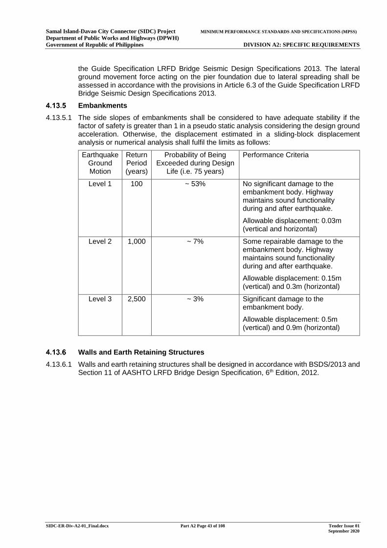
Samal Island-Davao City Connector (SIDC) Project MINIMUM PERFORMANCE STANDARDS AND SPECIFICATIONS (MPSS) Department of Public Works and Highways (DPWH) Government of Republic of Philippines DIVISION A2: SPECIFIC REQUIREMENTS
SIDC-ER-Div-A2-01_Final.docx Part A2 Page 43 of 108 Tender Issue 01 September 2020
the Guide Specification LRFD Bridge Seismic Design Specifications 2013. The lateral ground movement force acting on the pier foundation due to lateral spreading shall be assessed in accordance with the provisions in Article 6.3 of the Guide Specification LRFD Bridge Seismic Design Specifications 2013.
Embankments
4.13.5.1 The side slopes of embankments shall be considered to have adequate stability if the factor of safety is greater than 1 in a pseudo static analysis considering the design ground acceleration. Otherwise, the displacement estimated in a sliding-block displacement analysis or numerical analysis shall fulfil the limits as follows:
Earthquake Ground Motion
Return Period (years)
Probability of Being Exceeded during Design
Life (i.e. 75 years)
Performance Criteria
Level 1 100 ~ 53% No significant damage to the embankment body. Highway maintains sound functionality during and after earthquake.
Allowable displacement: 0.03m (vertical and horizontal)
Level 2 1,000 ~ 7% Some repairable damage to the embankment body. Highway maintains sound functionality during and after earthquake.
Allowable displacement: 0.15m (vertical) and 0.3m (horizontal)
Level 3 2,500 ~ 3% Significant damage to the embankment body.
Allowable displacement: 0.5m (vertical) and 0.9m (horizontal)
Walls and Earth Retaining Structures
4.13.6.1 Walls and earth retaining structures shall be designed in accordance with BSDS/2013 and Section 11 of AASHTO LRFD Bridge Design Specification, 6th Edition, 2012.
Samal Island-Davao City Connector (SIDC) Project MINIMUM PERFORMANCE STANDARDS AND SPECIFICATIONS (MPSS) Department of Public Works and Highways (DPWH) Government of Republic of Philippines DIVISION A2: SPECIFIC REQUIREMENTS
SIDC-ER-Div-A2-01_Final.docx Part A2 Page 44 of 108 Tender Issue 01 September 2020
5 SITE CLEARANCE
General Requirements
The Contractor shall identify and propose any buildings, structures and land formations that may require to be entirely or partially removed as a result of the Works for review and approval by the Engineer and relevant authorities. The Contractor shall reduce the impact to existing buildings, structures and land formations and if required to be removed, demonstrate such removal is necessary for the Works. No buildings, structures and land formations shall be demolished unless otherwise reviewed and approved by the Engineer and relevant authorities.
The Contractor shall identify and propose any existing facilities or features that need to be re-located for review and approval by the Engineer and relevant authorities. The Contractor shall agree with the Engineer and the respective owners on Site the exact relocated location of these facilities or features.
The Contractor shall ensure that any trees and vegetation which shall be required to be felled/removed to accommodate the Works shall be felled and disposed of in accordance with the requirements stated in Annex A5 Environmental Management and Monitoring of Employer’s Requirements Division A1.
Paving in the existing carriageway and footpath which will be within the extent of the future ground level roads or future formation, or made redundant as a result of the Works, shall be removed down to the existing sub-grade level.
All existing roads, tracks, hard standing areas, kerbs, gullies, road lighting columns, electrical installation infrastructure, barriers, signage and the like, made redundant as a result of the Works, and which are located within or adjacent to landscaped areas shall be removed to their full depth of construction, and the former location graded to appropriate levels and reinstated with subsoil and topsoil, to allow for planting or seeding to be undertaken.
Kerbs, gullies, lamp posts, barriers, signage and the like, made redundant as a result of the Works, and which are not located within landscaped areas shall be removed to their full depth of construction following review and approval of the Engineer, and the former location reinstated in accordance with the Employer’s Requirements Division A1 Annex A8.
The Contractor shall submit a Site Clearance and Demolition Proposal at least 30 days before the demolition starts, in accordance with the Review Procedure in Employer’s Requirements Division A1 General Requirements. The Proposal shall include particulars of the proposed methods of carrying out the demolition works, handling and sorting of recyclable materials, disposal of construction and demolition waste and re-location proposal of existing facilities. The Contractor shall demonstrate in the Proposal that the methods can ensure site safety, maximise recovery of materials for recycling or reuse, and minimise generation of construction and demolition waste.
Samal Island-Davao City Connector (SIDC) Project MINIMUM PERFORMANCE STANDARDS AND SPECIFICATIONS (MPSS) Department of Public Works and Highways (DPWH) Government of Republic of Philippines DIVISION A2: SPECIFIC REQUIREMENTS
SIDC-ER-Div-A2-01_Final.docx Part A2 Page 45 of 108 Tender Issue 01 September 2020
6 FENCING AND ENVIRONMENTAL BARRIERS
General
All defective and damaged parts of any existing or temporary boundary fencing shall be immediately repaired to ensure that the Site shall be secured and until such time as any walling, permanent fencing and accesses shall be completed.
All new gates at accesses shall allow for the gates to open away from the carriageway only.
Where temporary or permanent gates are to be locked, the Contractor shall provide and install the locks. Two sets of keys for each lock shall be provided to the Engineer.
Prior to executing any Works commencing in any area, a fence shall be erected to delineate the boundary of the Site in that area.
Temporary Fencing, Gates and the like
The temporary fencing shall be agreed by the Engineer.
The Contractor shall propose the extent, type and requirement of temporary fencing for the contractor works area and the site office for the approval of the Engineer.
Permanent Fencing, Gates and the like
Where existing fencing is affected, the Contractor shall re-provide the fencing similar to the existing. The re-provided fencing shall delineate the proposed right of way from the concerned land parcel/ site. The details of such works shall be submitted for review by the Engineer.
Chain link fence with a gate shall be provided to fence off the area under the bridge on Davao and Samal to prevent unauthorised access to the Abutment. The extent, type and location of the fencing and gate shall be determined on site with the Engineer.
Noise Fences and Barriers
Noise fences and barriers shall be provided in accordance with the ECC and EMP, if any. Refer to Annex A5 of Employer’s Requirements Division A1 for details.
7 ROAD RESTRAINT SYSTEMS
General Requirements
The layout of road restraint systems (vehicle restraint system and railings for the sidewalk and utilities corridor) shall follow the principles shown on the Drawings.
Vehicle Restraint System (VRS)
The Contractor shall provide VRS in accordance with the latest edition of the Department for Public Works and Highways, DGCS: Volume 4 – Highway Design and Highway Safety Design Standards Part 1: Road Safety Design Manual, and any other applicable standards as determined by the Engineer.
The type, shape and dimensions of the VRS shall comply with the Department for Public Works and Highways, DGCS Volume 4 – Highway Design and Highway Safety Design Standards Part 1: Road Safety Design Manual, and any other applicable standards as determined by the Engineer.
For the concrete VRS, discontinuity joints shall be provided at a maximum of 6m spacing, and considerations shall be given to reducing this spacing for short spans.
Samal Island-Davao City Connector (SIDC) Project MINIMUM PERFORMANCE STANDARDS AND SPECIFICATIONS (MPSS) Department of Public Works and Highways (DPWH) Government of Republic of Philippines DIVISION A2: SPECIFIC REQUIREMENTS
SIDC-ER-Div-A2-01_Final.docx Part A2 Page 46 of 108 Tender Issue 01 September 2020
The Contractor shall assess the risks in his proposed Works taking into consideration traffic flow, road geometry and surrounding environment to determine whether additional VRS are required, and if necessary, recommend suitable VRS for review and acceptance by the Engineer.
The Contractor shall design the layout of the VRS for safe and smooth transition between different types of VRS. The details shall be submitted to the Engineer for review and acceptance.
The Contractor shall design the end details of VRS for all situations. The details shall be submitted to the Engineer for review and acceptance.
Cyclist and Pedestrian Railings
For utility corridor and sidewalk on Bridge Structures and embankment structures, the restraint systems shall be in accordance with Chapter 18 of DGCS Volume 5 – Bridge Design.
The Contractor shall assess the risks in his proposed Works taking into consideration traffic and pedestrian flow, locations and safety of junctions or interchanges, road geometry and surrounding environment to determine whether additional railings are required, and if necessary recommend suitable arrangement of railings for review and acceptance by the Engineer.
Samal Island-Davao City Connector (SIDC) Project MINIMUM PERFORMANCE STANDARDS AND SPECIFICATIONS (MPSS) Department of Public Works and Highways (DPWH) Government of Republic of Philippines DIVISION A2: SPECIFIC REQUIREMENTS
SIDC-ER-Div-A2-01_Final.docx Part A2 Page 47 of 108 Tender Issue 01 September 2020
8 DRAINAGE
General Requirements
The design of stormwater drainage works such as culverts, drains, channels, kerb overflow weirs and gullies shall be in accordance with relevant standards and guidelines which include but are not limited to the following:
Department of Public Works and Highways Design Guidelines, Criteria and Standards (DGCS), Volume 3 Water Engineering Projects, 2015: This provides basic requirements and essential tools in the design preparation of water engineering projects specifically for flood control, water supply, coastal facilities and urban drainage infrastructures.
AASHTO, Highway Drainage Guidelines, 1992.
The Contractor shall be responsible for the design and construction of the new drainage system for the Works. Adequate silt trapping devices or similar shall be provided on road sections where surface run off is discharged into the sea.
The capacity of the existing drainage systems shall be checked for its suitability to receive any additional discharge from the Works. Unless necessary, the existing drainage systems shall not be modified. If modification has to be done, then proposed works and programme for implementation shall be submitted to the Engineer for review and agreed with the relevant authorities.
The Contractor shall take into account the impact of the drainage discharge of the proposed at-grade roads and bridge structures on land on to the existing drainage system and propose any modifications works if necessary. Close liaison should be carried out with the Engineer and relevant authorities regarding the design, construction and temporary traffic arrangement for the Works. The Contractor shall be responsible for the modification of the existing drainage system if required, then proposed works and programme for implementation shall be submitted to the Engineer for review and agreed with the relevant authorities.
Hydraulic capacity / adequacy of all the existing and proposed drains within the site boundary shall be carefully assessed and checked. Due consideration shall be made to the gravitational flow capacity or backwater effect as appropriate.
Adequate provision for proper trash screens, sand traps and maintenance access shall be provided for all proposed inlet structures.
The Contractor shall prepare a Temporary Drainage Management Plan (TDMP) prior to the replacement or re-provisioning of any of the existing drainage system. The TDMP shall be submitted to the Engineer for approval in accordance with the Review Procedure and agreed with any other relevant authorities before the implementation of new drainage system. The TDMP shall be updated at regular intervals during the course of the Contract to reflect the progress of the works and shall contain as a minimum the following details:
Where existing drainage paths are affected by the Works, the Contractor shall provide details of temporary drainage of capacity not less than the original.
Proposals for trapping of sediments.
A flood preventive maintenance schedule including frequency of inspection, location of inspection points and details of temporary works likely to obstruct flows.
Prior to demolishing/abandoning/diverting existing stormwater drain, the Contractor shall carry out site investigation to re-affirm that there are no live connection to the concerned drains and obtain the Engineer’s and other relevant authorities’ approvals. Also prior to connecting the proposed discharge to the existing drainage and sewerage systems, the
Samal Island-Davao City Connector (SIDC) Project MINIMUM PERFORMANCE STANDARDS AND SPECIFICATIONS (MPSS) Department of Public Works and Highways (DPWH) Government of Republic of Philippines DIVISION A2: SPECIFIC REQUIREMENTS
SIDC-ER-Div-A2-01_Final.docx Part A2 Page 48 of 108 Tender Issue 01 September 2020
Contractor shall seek approval from the Engineer and other relevant authorities for such connection.
Where pipes are being laid in an area where differential settlement and movement is anticipated (e.g. across the movement joint of bridge structure), due consideration for providing flexible joints / expansion joints shall be made. The proposed flexible joints / expansion joints shall be submitted to the Engineer for review in accordance with the Review Procedure.
The Contractor shall conduct a joint site survey with the Engineer of the existing drainage system, watercourse and/or stream course within the drainage reserve before commencement, during the course, and upon completion of the Works. The drainage reserve shall be 3m from both sides of the existing drainage system, watercourse and/or stream course.
Upon completion of the Works, the completed drainage system shall be surveyed by Closed Circuit Television (CCTV) or appropriate means. The details of the method and process shall be agreed on site with the Engineer.
Drainage System Design Parameters and Requirements
Unless stated otherwise, the drainage of surface water for the bridge structures and at-grade road shall be as separate collection systems. Disposal shall be effected by one of the following separate systems:
(a) surface water by gravity into the sea;
(b) surface water pumped into the sea.
For the sections of the Works on Davao, some existing drainage pipes may be modified. Close liaison with local authorities shall be conducted to formulate the temporary or permanent drainage diversion scheme. Should it be necessary to modify existing drainage systems then the Contractor shall seek approval from the Engineer, and other relevant authorities for such modification.
Combined utilities drawings shall be prepared to detect clashes to existing or proposed structures and utilities. These shall be submitted to the Engineer for review in accordance with the Review Procedure before the execution of works.
Materials submission shall be prepared and submitted to relevant authorities for approval and the Engineer for review in accordance with the Review Procedure.
Adequate crossfall shall be provided on bridge structures to shed stormwater to the drainage intakes.
Manholes and Chambers Manholes shall be provided at:
intersection of drain pipes;
junction between different size of drain pipes;
locations where the drain pipe changes direction / gradient;
on long straight lengths at a maximum interval of 60m.
Inspection chambers shall be provided at:
Intersection of channels;
Locations where the channel changes direction;
on long straight lengths at a maximum interval of 60m.
Samal Island-Davao City Connector (SIDC) Project MINIMUM PERFORMANCE STANDARDS AND SPECIFICATIONS (MPSS) Department of Public Works and Highways (DPWH) Government of Republic of Philippines DIVISION A2: SPECIFIC REQUIREMENTS
SIDC-ER-Div-A2-01_Final.docx Part A2 Page 49 of 108 Tender Issue 01 September 2020
Channel/ gully gratings and manhole covers shall be sufficiently strong to take the live load of the heaviest vehicle and shall be durable for the environmental conditions in Philippines. Heavy-duty manhole covers shall be used when traffic or heavy loading is anticipated, otherwise medium duty covers may be used.
Channel/ gully gratings and manhole covers shall not rock in position when initially placed in position or develop a rock with wear.
A minimum soil cover of 300 mm shall be provided for the new drainage works below the final ground/bank level.
The design of temporary works shall not affect the capacity of the main drainage system.
Samal Island-Davao City Connector (SIDC) Project MINIMUM PERFORMANCE STANDARDS AND SPECIFICATIONS (MPSS) Department of Public Works and Highways (DPWH) Government of Republic of Philippines DIVISION A2: SPECIFIC REQUIREMENTS
SIDC-ER-Div-A2-01_Final.docx Part A2 Page 50 of 108 Tender Issue 01 September 2020
9 GANTRY STRUCTURAL REQUIREMENTS
Gantry Requirements
The Contractor shall provide sign gantries where required for the traffic signs. The sign gantries shall be detailed and constructed in accordance with the latest edition of the Department for Public Works and Highways, Highway Safety Design Standards Part 2: Road Signs and Pavement Markings Manual, and any other applicable standards as determined by the Engineer.
The bridge superstructure shall be designed to carry the design loading from the gantries. The design of the gantries’ connection or foundation shall be submitted to the Engineer for review in accordance with the Review Procedure.
All steelwork shall comply with the requirements of the Structural Design Basis in Annex C to this Employer’s Requirement Division A2. In addition, steelwork on Bridge Structures shall be protected using a corrosion protection system in accordance with the requirements in the Structural Design Basis as appropriate.
The Contractor’s proposed protective systems, including the full specification shall be submitted to the Engineer for review in accordance with the Review Procedure prior to execution of any relevant part of the Works.
Gantry sign lighting and power supply systems shall be provided for the traffic signs as specified in Section 14.
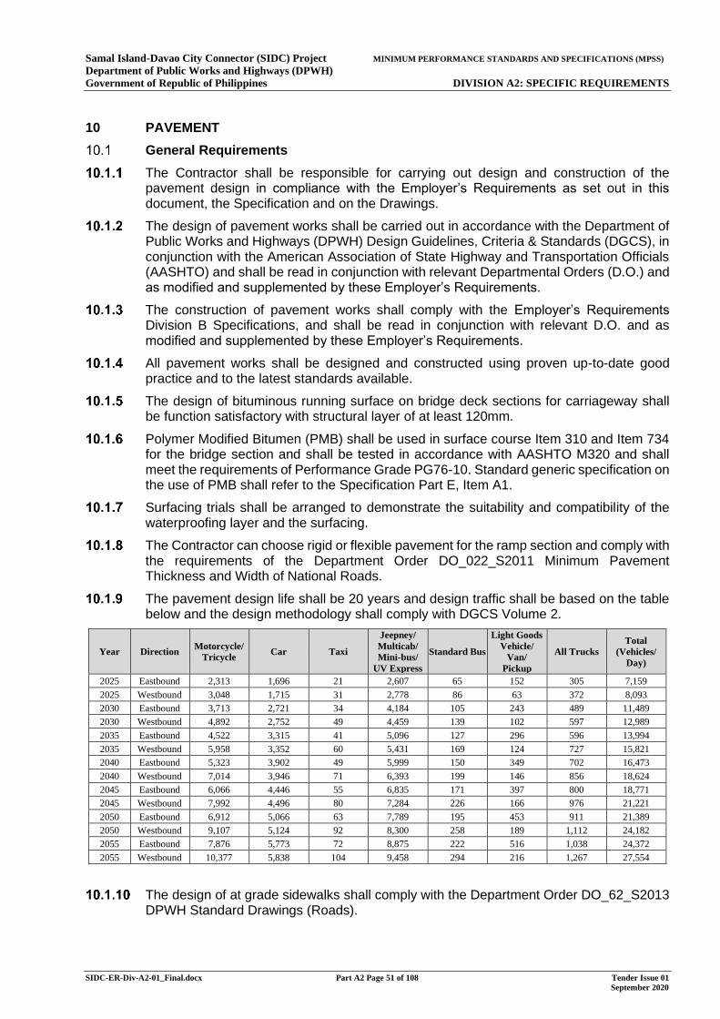
Samal Island-Davao City Connector (SIDC) Project MINIMUM PERFORMANCE STANDARDS AND SPECIFICATIONS (MPSS) Department of Public Works and Highways (DPWH) Government of Republic of Philippines DIVISION A2: SPECIFIC REQUIREMENTS
SIDC-ER-Div-A2-01_Final.docx Part A2 Page 51 of 108 Tender Issue 01 September 2020
10 PAVEMENT
General Requirements
The Contractor shall be responsible for carrying out design and construction of the pavement design in compliance with the Employer’s Requirements as set out in this document, the Specification and on the Drawings.
The design of pavement works shall be carried out in accordance with the Department of Public Works and Highways (DPWH) Design Guidelines, Criteria & Standards (DGCS), in conjunction with the American Association of State Highway and Transportation Officials (AASHTO) and shall be read in conjunction with relevant Departmental Orders (D.O.) and as modified and supplemented by these Employer’s Requirements.
The construction of pavement works shall comply with the Employer’s Requirements Division B Specifications, and shall be read in conjunction with relevant D.O. and as modified and supplemented by these Employer’s Requirements.
All pavement works shall be designed and constructed using proven up-to-date good practice and to the latest standards available.
The design of bituminous running surface on bridge deck sections for carriageway shall be function satisfactory with structural layer of at least 120mm.
Polymer Modified Bitumen (PMB) shall be used in surface course Item 310 and Item 734 for the bridge section and shall be tested in accordance with AASHTO M320 and shall meet the requirements of Performance Grade PG76-10. Standard generic specification on the use of PMB shall refer to the Specification Part E, Item A1.
Surfacing trials shall be arranged to demonstrate the suitability and compatibility of the waterproofing layer and the surfacing.
The Contractor can choose rigid or flexible pavement for the ramp section and comply with the requirements of the Department Order DO_022_S2011 Minimum Pavement Thickness and Width of National Roads.
The pavement design life shall be 20 years and design traffic shall be based on the table below and the design methodology shall comply with DGCS Volume 2.
Year Direction Motorcycle/ Tricycle Car Taxi
Jeepney/ Multicab/ Mini-bus/
UV Express
Standard Bus
Light Goods Vehicle/
Van/ Pickup
All Trucks Total
(Vehicles/ Day)
2025 Eastbound 2,313 1,696 21 2,607 65 152 305 7,159
2025 Westbound 3,048 1,715 31 2,778 86 63 372 8,093 2030 Eastbound 3,713 2,721 34 4,184 105 243 489 11,489 2030 Westbound 4,892 2,752 49 4,459 139 102 597 12,989
2035 Eastbound 4,522 3,315 41 5,096 127 296 596 13,994 2035 Westbound 5,958 3,352 60 5,431 169 124 727 15,821 2040 Eastbound 5,323 3,902 49 5,999 150 349 702 16,473
2040 Westbound 7,014 3,946 71 6,393 199 146 856 18,624 2045 Eastbound 6,066 4,446 55 6,835 171 397 800 18,771 2045 Westbound 7,992 4,496 80 7,284 226 166 976 21,221
2050 Eastbound 6,912 5,066 63 7,789 195 453 911 21,389 2050 Westbound 9,107 5,124 92 8,300 258 189 1,112 24,182 2055 Eastbound 7,876 5,773 72 8,875 222 516 1,038 24,372
2055 Westbound 10,377 5,838 104 9,458 294 216 1,267 27,554
The design of at grade sidewalks shall comply with the Department Order DO_62_S2013 DPWH Standard Drawings (Roads).
Samal Island-Davao City Connector (SIDC) Project MINIMUM PERFORMANCE STANDARDS AND SPECIFICATIONS (MPSS) Department of Public Works and Highways (DPWH) Government of Republic of Philippines DIVISION A2: SPECIFIC REQUIREMENTS
SIDC-ER-Div-A2-01_Final.docx Part A2 Page 52 of 108 Tender Issue 01 September 2020
All pavement surface shall provide adequate skid resistance surface. For ramp with gradients 5% to 10% and length longer than 50m, Contactor shall design and select the pavement surface to provide adequate skid resistance. Where required, Item 735 Porous Asphalt Mixture with PMB PG76-10 as open graded surface course can be laid on top of concrete pavement or asphalt pavement to improve the skid resistance.
Vehicular Bridge Waterproofing
Waterproofing shall be provided on the whole bridge deck. In general, the waterproofing applied on the bridge deck shall consist of furnishing and applying a liquid applied elastomer waterproofing membrane system to suitable concrete bridge deck surfaces. Liquid applied elastomer waterproofing consists of a coating of primer, a one or two coat elastomer membrane applied by wither rollers or spraying, and a UV stable tack or wearing coat.
The liquid applied elastomer water proofing membrane system shall meet the requirements specified in the construction specification Section 21 Clause 21.6 of Part F of the Specification, unless otherwise approved by the Engineer. The type and specification of waterproofing to be applied under this Contract shall be submitted for relevant parties’ comments and subjected to the Engineer’s approval.
The adhesion and bond achieved for a waterproofing system shall be consistent with that expected for the system. The adhesion and bond at all interfaces of the waterproofing system shall be uniform in order to ensure the durability of the concrete deck, waterproofing system and surfacing.
The waterproofing systems specified for use on the concrete bridge decks shall have an assumed intended minimum working life of 25 years.
The vehicular bridge structures shall be designed to be finished with bituminous materials, which can be readily repaired or replaced over the life of the structure. For concrete bridge deck with waterproofing membrane, the minimum thickness of asphalt surfacing shall be 120mm excluding the friction course thickness.
Surfacing trials shall be arranged to demonstrate the suitability and compatibility of the waterproofing layer and the surfacing.
11 KERBS, FOOTPATHS AND PAVED AREAS
General
The design of the Works shall comply with DGCS: Volume 4 – Highways Design and Annex B Highway Design Basis and any other applicable standards as determined by the Engineer.
Kerbs
Kerbing shall be provided for the Works following the principles shown on the Drawings, including the following:
(i) all turning areas;
(i) all lay-bys and bus lay-bys; and
(ii) all non-motorised Users crossings.
Kerbs and edgings shall conform to DGCS: Volume 4 – Highways Design, construction specification Part H of the Specifications and DPWH Standard Design Drawings (Roads) Departmental Order No. 62 Series of 2013 or the latest equivalent DPWH Standard Design Drawings.
Sidewalk and Sidewalk/ Cycleways
Samal Island-Davao City Connector (SIDC) Project MINIMUM PERFORMANCE STANDARDS AND SPECIFICATIONS (MPSS) Department of Public Works and Highways (DPWH) Government of Republic of Philippines DIVISION A2: SPECIFIC REQUIREMENTS
SIDC-ER-Div-A2-01_Final.docx Part A2 Page 53 of 108 Tender Issue 01 September 2020
The term “sidewalk/ cycleways” in these Employer’s Requirements and the Drawings refers to the combined facility for shared use by pedestrians and cyclists.
Sidewalks and sidewalk/ cycleways shall include but shall not be limited to those shown on the drawings and described elsewhere in these Employer’s Requirements.
Sidewalks and sidewalk/ cycleways in the Works shall tie-in to existing and planned sidewalks and sidewalk/ cycleways at all interfaces and extremities of existing and planned sidewalks and sidewalk/ cycleways respectively.
Allowance shall be made by the Contractor in the design of the Works to accommodate widths and tie-ins and any other features affecting the width and the like of the sidewalks and sidewalk/ cycleways.
The pavement design of the Works for sidewalks and sidewalk/ cycleways shall refer to Section 10.
Sidewalks and sidewalk/ cycleways in the design of the Works shall be constrained by pre-cast concrete kerbing and edging as required and agreed with the Engineer.
The asphaltic layers of sidewalks and sidewalk/ cycleways shall be machine laid.
The pavement material shall comply with the requirements of the Specification.
All sidewalks and sidewalk/ cycleways in the design of the Works shall incorporate sufficient drainage to ensure that they shall be kept free from standing water.
At crossing points, dropped kerbs shall be provided in accordance the Employer’s Requirements and relevant standards and specifications. .
Paved Areas
Deflection islands and pedestrian refuge islands shall be paved with 80 millimetre deep concrete paviours or 80 millimetre deep concrete slab whichever will match with existing footpaths, if any, in the surrounding area.
12 TRAFFIC STUDY
General Requirements
The Contractor shall undertake a comprehensive traffic study to confirm that the proximity of the ramps’ terminal points to the existing intersections along R. Castillo St. and Daang Maharlika Highway complies with the relevant requirements of the BOD and the relevant authorities. The study shall include but not limited to the following;
Traffic study for the Filipinas St. – Daang Maharlika Highway Intersection and N. Arroyo St. R. Castillo St. intersections (including phasing diagram indicating the traffic composition, volume, design vehicle, among others for each leg) which become the basis/ reference in the proposed improvement of the intersection layout. Also, conduct a comprehensive study to address the different traffic conflicts at said intersections for both signalized or unsignalized condition/ type.
Verification that the sight distance and safe stopping distance requirements are satisfied.
Proposed traffic control devices that will inform and properly guide the drivers on approaching intersection; and that the turning/ maneuvering at the intersection will not impede the safe and smooth flow of traffic coming from and going to the bridge and prevent queuing at the intersection.
The Contractor shall submit the following;
Samal Island-Davao City Connector (SIDC) Project MINIMUM PERFORMANCE STANDARDS AND SPECIFICATIONS (MPSS) Department of Public Works and Highways (DPWH) Government of Republic of Philippines DIVISION A2: SPECIFIC REQUIREMENTS
SIDC-ER-Div-A2-01_Final.docx Part A2 Page 54 of 108 Tender Issue 01 September 2020
Complete plan and profile of the above-mentioned intersections indicating the exact locations of up/down ramp terminal points; and
Complete intersection layout (signalized or unsignalized) indicating the required turning radius for the design vehicles, location of islands/channelization, pavement markings, road signages, provision of accessibility for Person With Disability (PWD), among others. See also the requirements under Section 13.
13 TRAFFIC SIGN, ROAD MARKINGS AND STUDS
General Obligations
The Contractor shall consult and comply with the requirements of the Engineer and the relevant local authorities with regard to all details for the provision of traffic signs and road markings for the Works.
Design Standards and Manuals
The Contractor shall allow at least 84 days for the making and publication of any amendments to the existing local authority traffic orders required as a part of the design of the Works.
The Contractor shall comply with the requirements of Highway Safety Design Standards 2012, issued by the Department of Public Works and Highways of the Republic of the Republic of the Philippines (DPWH);
Part 1: Road Safety Design Manual
Part 2: Road Signs and Pavement Markings
The Contractor shall also refer to the following supplemental standards:
A Guide to Traffic Engineering and Management Techniques, Metro Manila Traffic Engineering and Management Project
Road Works Safety Manual, DPWH, 2004
Guidelines for the Preparation of Cost Estimates for Traffic Management and Safety & Health Requirements for the Construction and Maintenance of Roads, Bridges and Safety & Health Requirements for School Buildings, DPWH, 2018
Manual on Uniform Traffic Control Devices, US DOT- FHWA, 2009
Urban Street Design Guide, NACTO
If the Contractor wishes to use traffic signs or markings that are not prescribed by the DPWH Highway Safety Design Standards 2012 and/or the supplemental standards, the Contractor shall obtain approval from the relevant local authority and the Engineer.
Traffic Signs
Traffic signals (warning, regulatory and information) shall be identified and placed according to the requirements of the DPWH Highway Safety Design Standards 2012.
Traffic sign faces, posts, and foundations shall be provided in the Works for all roads as described in the Employer’s Requirements and relevant standards and specifications.
Road Markings
Road markings design shall comply with the requirements of DPWH Highway Safety Design Standards 2012.
Road pavement markings should be of non-skid materials and should not protrude more than 6mm above the level of the carriageway. Raised pavement markers (e.g. reflectorized
Samal Island-Davao City Connector (SIDC) Project MINIMUM PERFORMANCE STANDARDS AND SPECIFICATIONS (MPSS) Department of Public Works and Highways (DPWH) Government of Republic of Philippines DIVISION A2: SPECIFIC REQUIREMENTS
SIDC-ER-Div-A2-01_Final.docx Part A2 Page 55 of 108 Tender Issue 01 September 2020
markings) on concrete roads should not protrude more than 25mm above the level of the carriageway.
Traffic Signals
Traffic signals shall be installed on intersections as specified by the Engineer.
The Contractor shall conform to the requirements of the Technical Specification for Microprocessor Traffic Signal Controller for Use in the Philippines, issued by the Traffic Engineering and Management (TEAM) of DPWH.
The Contractor shall conform to the control mode and signal systems prescribed by DPWH and/or the City Transport and Traffic Management Office (CTMO) of Davao City Local Government Unit (LGU) or other local authority.
The design, illumination, colour, and shape specifications of traffic control signals shall conform to the Manual on Uniform Traffic Control Devices 2009 by US DOT-FWHA.
Structural support of the traffic control signals shall conform to the provisions of Specifications for Structural Supports for Highway Signs, Luminaires, and Traffic Signals by AASHTO, and the provision specified in Section 14.15.
Samal Island-Davao City Connector (SIDC) Project MINIMUM PERFORMANCE STANDARDS AND SPECIFICATIONS (MPSS) Department of Public Works and Highways (DPWH) Government of Republic of Philippines DIVISION A2: SPECIFIC REQUIREMENTS
SIDC-ER-Div-A2-01_Final.docx Part A2 Page 56 of 108 Tender Issue 01 September 2020
14 ELECTRICAL WORKS
General
The Contractor shall design, manufacture, supply, deliver to site, install, test and commission the electrical systems, including provision of spares and training for the operation, inspection and maintenance of the electrical systems in accordance with this Section 14 and construction specification Part J of the Specification. This Section 13 applies to all electrical works of the Project except those inside the Administration Building, which is separately covered by Section 18 of this document.
The Contractor shall conduct a detailed site survey, including but not limited to identifications of the existing power cables and communication cables, and liaise with the related parties to ascertain the diversion requirements to enable the new installations for the bridge.
The Contractor shall conduct the diversion of the existing utilities as necessitated by this project, with due considerations taken on the ongoing live operations of any adjacent roadways, facilities, and buildings.
The Contractor shall liaise with the relevant energy authorities in Davao City and Samal Island to obtain mains power supply from at least two separately derived electricity mains sources.
The Contractor shall be responsible in coordination and liaison with other trade contractors to ensure that the systems can be installed and are in accordance with the requirement of the Contractor itself and the other parties.
The scope of works shall include the following design, manufacture, supply, deliver to site, install, test and commission, but not limited to:
a) Mains power supply system and distribution with the associated control equipment for power supply of road lighting, gantry and traffic sign lighting, lighting in bicycle and pedestrian access facility , lighting and small power for inspectable space inside bridge structures (e.g. internal space of bridge tower, caisson foundation and box girder cell, etc if such space exists) and aviation warning lights;
b) Power supply installation including power distribution boards, fuse cut-out, power cables, cable containment, switchgears, lighting, power outlet points, interfacing marshalling cabinet and all other necessary accessories for the purpose of distribution of mains power supplies;
c) Luminaires, lamp sources, timer, photoelectric sensors, lighting columns, enclosures, mounting accessories, control gear, ballast, ignitor, earthing, lightning protection, cable containment and wiring connections for a complete road lighting system and gantry lighting system;
d) Mains power supply system and distribution with the associated control equipment, earthing, lightning protection, cable containment and wiring connections for power supply of deck cell lighting & small power;
e) Provision of Mains power supply for the plumbing systems, aviation warning lighting, network switches and other extra low voltage equipment/panels, SCADA and/or other control/monitoring systems, and traffic signals, including liaison with the relevant energy authorities in Davao City and Samal Island for such power supply;
f) Cabling, laying, jointing and termination of cables for all electrical equipment;
g) Cable containment systems for electrical installations, traffic management systems, gantry sign and traffic sign lighting, road lighting, deck cell lighting/small power,
Samal Island-Davao City Connector (SIDC) Project MINIMUM PERFORMANCE STANDARDS AND SPECIFICATIONS (MPSS) Department of Public Works and Highways (DPWH) Government of Republic of Philippines DIVISION A2: SPECIFIC REQUIREMENTS
SIDC-ER-Div-A2-01_Final.docx Part A2 Page 57 of 108 Tender Issue 01 September 2020
navigation lighting, control wirings, telecommunication providers cabling, and other installations with requirements to run cables along the Project to and from the administration building;
h) Conduit wiring system comprising cables, cable conduits, electrical accessories and flexible conduits where necessary for the complete lighting installation;
i) Final circuit distribution for lighting and small power point comprising wiring, the associated containment system and electrical accessories including small power socket outlet, switch, isolator, fused spur unit, connection box, control box, etc.;
j) Not used.
k) Lightning protection system, earthing connection to the earth link for the equipment and accessories along the entire length of the Project including equipotential bonding system;
l) Coordination with the relevant energy authorities in Davao City and Samal Island for detailed design and implementation of lighting arrangement together with lighting calculations for road lighting and gantry sign lighting and the design parameters as stated in this Specification. Submission shall be made to the Engineer, the relevant energy authorities in Davao City and Samal Island and other relevant authorities for review and approval;
m) Necessary electrical installations, power points, and provisions for other trades and systems not described within this specification section.
All associated wirings, instrumentations, firmware, software, and other non-hardware goods necessary to complete the installations and systems shall also be part of the scope of works.
The Contractor shall liaise with the relevant Authorities Having Jurisdictions to obtain approval, permits, stamps, or the like for all the associated installations prior to the siteworks, during the construction, and after the installation is completed.
The Contractor shall also be responsible for providing the Professional Engineer signatures and stamps for all the required documentations.
Complete copies of the following schedules shall be submitted prior to the commencement of the detailed design:
Schedule of Standards, Regulations and Statutory Requirements for MEP Systems and Installations;
Schedule of Manufacturers’ and Suppliers’ products of MEP systems; and
Schedule of Tests and Commissioning of MEP Systems and Installations.
The Contractor shall clearly identify all alterations and/or additions made to the respective schedule from that submitted as part the Contractor’s Detailed Engineering Design Report.
The Contractor shall submit the Preliminary Design, Detailed Engineering Design, Design Documentation and all other relevant submissions in accordance with the Review Procedure for review by the Engineer, and the relevant energy authorities in Davao City and Samal Island. The submissions shall cover the design of the Electrical Works as described in this Section 14 and the operation and maintenance requirements as specified in the Employer’s Requirements.
Dedicated distribution boards shall be provided for superstructure deck cell lighting and other inspectable space inside any components of the Bridge Structures if any. Distribution boards for other system equipment shall be also provided as required. Unless
Samal Island-Davao City Connector (SIDC) Project MINIMUM PERFORMANCE STANDARDS AND SPECIFICATIONS (MPSS) Department of Public Works and Highways (DPWH) Government of Republic of Philippines DIVISION A2: SPECIFIC REQUIREMENTS
SIDC-ER-Div-A2-01_Final.docx Part A2 Page 58 of 108 Tender Issue 01 September 2020
otherwise approved by the Engineer, and the relevant energy authorities, supplies provided to electrical equipment other than those specified in the Specification, internal and external to the Project, shall not be connected to the Project’s Network.
Where applicable, the minimum fire resistance rating of the fire resistance panel (FRP) for the enclosure of the services such as equipment, electrical work, etc. shall be the same fire resisting period as the serviced compartment or the containment compartment whichever is higher.
Any metallic covers or enclosures for electrical equipment inside deck cells shall be treated with anti-corrosion and anti-rust paint.
Post-fixing of elements to the concrete and/or steel where applicable shall only be permitted if the post-fixing process poses no risk to the reinforcement and/or prestressing within the concrete and/or steel structures and agreement shall be obtained from the Engineer, and the relevant energy authorities.
The Contractor shall conduct a thorough and complete testing and commissioning of the electrical systems and provide all support systems for electrical systems.
The Contractor shall be responsible to conduct a full discrimination study and select the appropriate circuit breaker configurations to ascertain full discrimination across the electrical distribution network. Any overcurrent or fault event occurring in one of the electrical circuits will be isolated by the nearest upstream protective device for that affected circuit and shall not cause nuisance tripping on the other live circuits. The full discrimination report shall be made available to the Engineer and the Authorities Having Jurisdiction for review, comment, and approval prior to ordering of equipment.
The earth fault and/or earth leakage protection relays shall be provided with adequate adjustment ranges such that any inherent earth leakages in the system can be considered in the protection settings such that nuisance tripping in the system can be avoided.
The Contractor shall produce as-built and as-fitted drawings for the entire systems in this project in AutoCAD (or similar industry accepted format) and PDF formats. The drawings shall be stamped, endorsed, and certified according to the local governing laws and code of practices. Both soft-copy and hard-copy of the drawings shall be furnished to the Engineer for record keeping, operation, and maintenance purposes.
No medium-voltage and low-voltage cable joints shall be accepted unless with prior discussions and agreement with the Engineer. The Contractor shall make every effort to supply and install new power cables in whole uncut length.
All panel enclosures and pillar boxes installed in this project shall be constructed of corrosion and rust resistant Stainless Steel 316 material and weatherproofed to IP66.
All other equipment, devices, raceways shall be weatherproof to IP66 or NEMA 3R, whichever provides higher degree of protection.
The Contractor shall consider movement joints in the electrical installations and appropriate fittings provided to overcome them. Particular attention shall be paid to the bridge movements joints which need to cater for both permanent and reversible movements.
The Contractor shall provide maintenance, servicing, and repair during the Defect Notification Period.
The electrical systems shall be designed and provided based on the following local codes and international standards or Philippines equivalent to the acceptance of the Engineer:
(a) NEMA, IEEE, and UL
(b) The latest Philippine Electrical Code (PEC) Part 1 and Part 2;
Samal Island-Davao City Connector (SIDC) Project MINIMUM PERFORMANCE STANDARDS AND SPECIFICATIONS (MPSS) Department of Public Works and Highways (DPWH) Government of Republic of Philippines DIVISION A2: SPECIFIC REQUIREMENTS
SIDC-ER-Div-A2-01_Final.docx Part A2 Page 59 of 108 Tender Issue 01 September 2020
(c) The latest Roadway Lighting Guidelines issued by the Department of Energy of the Republic of the Philippines;
(d) The latest Design Guidelines, Criteria and Standards (DGCS) Volume 4 – Highway Design issued by the Department of Public Works and Highways of the Republic of the Philippines;
(e) The latest IEC International Standards;
(f) Requirements and Regulations of the Local Authority and Authorities Having Jurisdictions (AHJ);
(g) The latest edition of Roadway Lighting Design Guide issued by the American Association of State Highway and Transportation Officials (AASHTO);
(h) The latest version of CIE 140;
(i) Prevailing local code of practices and standards with respect to health and safety and work, workplace regulations, construction regulations, factories and industrial undertaking ordinances, electricity at work regulations, and others;
(j) Electromagnetic Compatibility Regulations;
(k) AASHTO LTS 2 Standard Specifications for Structural Supports for Highway Signs, Luminaries and Traffic Signals
(l) ASTM A 36 Structural Steel
(m) ASTM A 123 Zinc (Hot Dip Galvanized) Coatings on Iron and Steel Products
(n) ASTM A 143 Practice for Safeguarding Against Embrittlement of Hot Dip Galvanized Structural Steel Products and Procedure for Detecting Embrittlement
(o) ASTM A 153 Zinc Coating (Hot Dip) on Iron and Steel Hardware
(p) ASTM A 615 Deformed and Billet Steel Bars for Concrete Reinforcement
(q) ASTM A 572 High Strength Low Alloy Columbium Vanadium Steel of Structural Quality
(r) AISC Specification for the Design, Fabrication and Erection of Structural Steel for Buildings.
(s) ASTM A 595 Steel Tubes, Low Carbon, Tapered for Structural Use
(t) Applicable standards governed by the American Welding Society
In the event of discrepancies in the governing standards above, the most stringent one shall prevail and be followed through.
All equipment shall comply with the product particular requirement of the Department of Energy Philippine Energy Standard and Labelling Program to be installed and shall bear the Certification Mark (Philippine Standard Quality Mark or Import Commodity Clearance) issued by the Department of Trade and Industry-Bureau of Product Standards (DTI-BPS) for specific purposes
In addition to this specification, the Contractor shall also comply to the clauses outlined in construction specification Part J of the Specification. In the event of any contradicting and/or clauses with differing level of requirements, the more stringent clauses shall prevail.
The Contractor shall provide program logic controller-based (PLC-based) SCADA control and monitoring systems for equipment and devices installed along the Project.
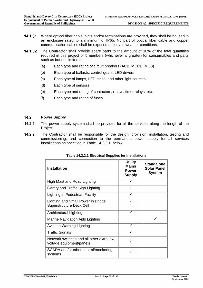
Samal Island-Davao City Connector (SIDC) Project MINIMUM PERFORMANCE STANDARDS AND SPECIFICATIONS (MPSS) Department of Public Works and Highways (DPWH) Government of Republic of Philippines DIVISION A2: SPECIFIC REQUIREMENTS
SIDC-ER-Div-A2-01_Final.docx Part A2 Page 60 of 108 Tender Issue 01 September 2020
Where optical fiber cable joints and/or terminations are provided, they shall be housed in an enclosure rated to a minimum of IP65. No part of optical fiber cable and copper communication cables shall be exposed directly to weather conditions.
The Contractor shall provide spare parts to the amount of 10% of the total quantities required in this project or 5 numbers (whichever is greater) for consumables and parts such as but not limited to:
(a) Each type and rating of circuit breakers (ACB, MCCB, MCB)
(b) Each type of ballasts, control gears, LED drivers
(c) Each type of lamps, LED strips, and other light sources
(d) Each type of sensors
(e) Each type and rating of contactors, relays, timer relays, etc.
(f) Each type and rating of fuses
Power Supply
The power supply system shall be provided for all the services along the length of the Project.
The Contractor shall be responsible for the design, provision, installation, testing and commissioning, and connection to the permanent power supply for all services installations as specified in Table 14.2.2.1 below:
Table 14.2.2.1 Electrical Supplies for Installations
Installation
Utility Mains Power Supply
Standalone Solar Panel
System
High Mast and Road Lighting ✓
Gantry and Traffic Sign Lighting ✓
Lighting in Pedestrian Facility ✓
Lighting and Small Power in Bridge Superstructure Deck Cell
✓
Architectural Lighting ✓
Marine Navigation Aids Lighting ✓
Aviation Warning Lighting ✓
Traffic Signals ✓
Network switches and all other extra low voltage equipment/panels
✓
SCADA and/or other control/monitoring systems
✓
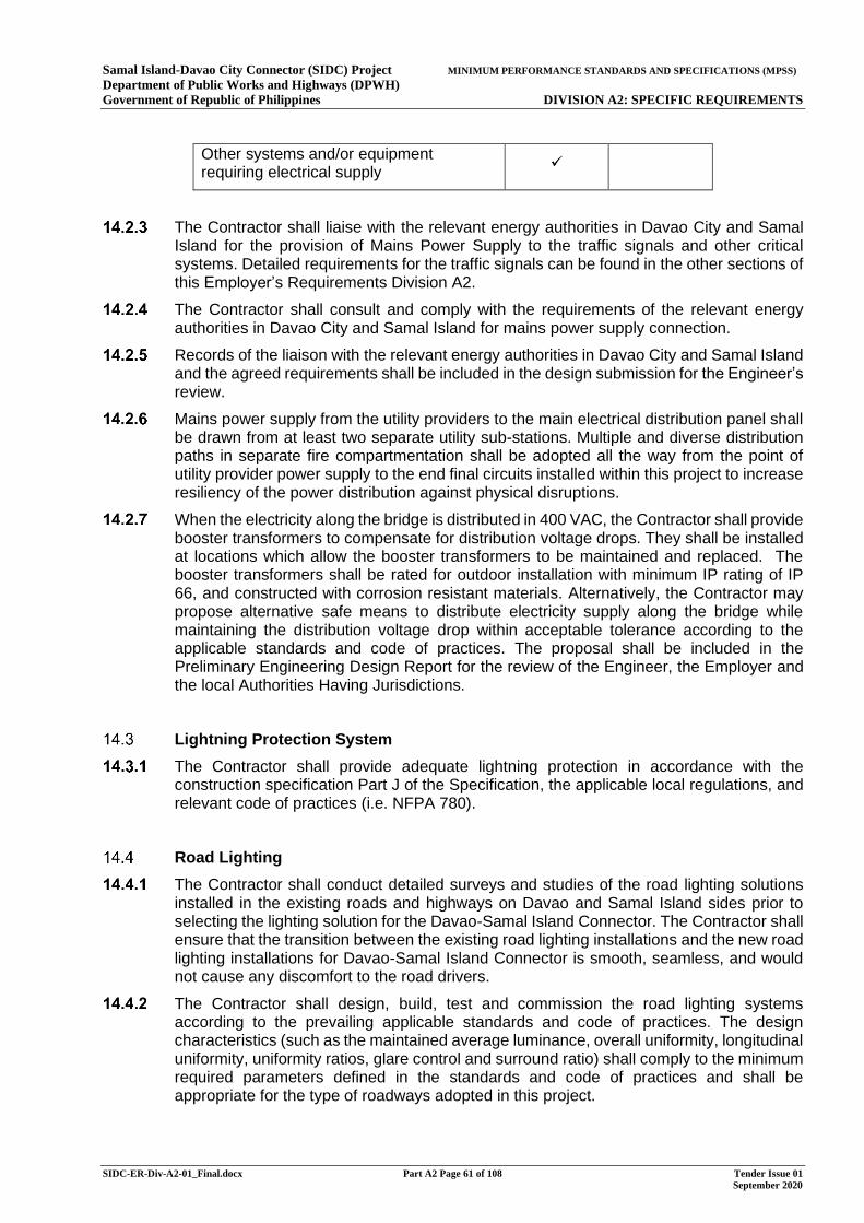
Samal Island-Davao City Connector (SIDC) Project MINIMUM PERFORMANCE STANDARDS AND SPECIFICATIONS (MPSS) Department of Public Works and Highways (DPWH) Government of Republic of Philippines DIVISION A2: SPECIFIC REQUIREMENTS
SIDC-ER-Div-A2-01_Final.docx Part A2 Page 61 of 108 Tender Issue 01 September 2020
Other systems and/or equipment requiring electrical supply ✓
The Contractor shall liaise with the relevant energy authorities in Davao City and Samal Island for the provision of Mains Power Supply to the traffic signals and other critical systems. Detailed requirements for the traffic signals can be found in the other sections of this Employer’s Requirements Division A2.
The Contractor shall consult and comply with the requirements of the relevant energy authorities in Davao City and Samal Island for mains power supply connection.
Records of the liaison with the relevant energy authorities in Davao City and Samal Island and the agreed requirements shall be included in the design submission for the Engineer’s review.
Mains power supply from the utility providers to the main electrical distribution panel shall be drawn from at least two separate utility sub-stations. Multiple and diverse distribution paths in separate fire compartmentation shall be adopted all the way from the point of utility provider power supply to the end final circuits installed within this project to increase resiliency of the power distribution against physical disruptions.
When the electricity along the bridge is distributed in 400 VAC, the Contractor shall provide booster transformers to compensate for distribution voltage drops. They shall be installed at locations which allow the booster transformers to be maintained and replaced. The booster transformers shall be rated for outdoor installation with minimum IP rating of IP 66, and constructed with corrosion resistant materials. Alternatively, the Contractor may propose alternative safe means to distribute electricity supply along the bridge while maintaining the distribution voltage drop within acceptable tolerance according to the applicable standards and code of practices. The proposal shall be included in the Preliminary Engineering Design Report for the review of the Engineer, the Employer and the local Authorities Having Jurisdictions.
Lightning Protection System
The Contractor shall provide adequate lightning protection in accordance with the construction specification Part J of the Specification, the applicable local regulations, and relevant code of practices (i.e. NFPA 780).
Road Lighting
The Contractor shall conduct detailed surveys and studies of the road lighting solutions installed in the existing roads and highways on Davao and Samal Island sides prior to selecting the lighting solution for the Davao-Samal Island Connector. The Contractor shall ensure that the transition between the existing road lighting installations and the new road lighting installations for Davao-Samal Island Connector is smooth, seamless, and would not cause any discomfort to the road drivers.
The Contractor shall design, build, test and commission the road lighting systems according to the prevailing applicable standards and code of practices. The design characteristics (such as the maintained average luminance, overall uniformity, longitudinal uniformity, uniformity ratios, glare control and surround ratio) shall comply to the minimum required parameters defined in the standards and code of practices and shall be appropriate for the type of roadways adopted in this project.
Samal Island-Davao City Connector (SIDC) Project MINIMUM PERFORMANCE STANDARDS AND SPECIFICATIONS (MPSS) Department of Public Works and Highways (DPWH) Government of Republic of Philippines DIVISION A2: SPECIFIC REQUIREMENTS
SIDC-ER-Div-A2-01_Final.docx Part A2 Page 62 of 108 Tender Issue 01 September 2020
The roadway lighting shall be designed such that the farthest luminaire in the branch circuit, if any, shall operate within the voltage supply level of 230 VAC ±10%.
Appropriate luminaire maintenance factor shall be considered in the design, simulation, and calculation process, and in any case shall not be less than 0.5.
The Contractor shall provide permanent road lighting over the entire road alignment of the Project and the area under the approach viaduct decks at Samal Island and Davao City. The road lighting design shall comply with the requirements given in this specification and other prevailing applicable standards.
The road lighting shall be LED type luminaire mounted on lighting columns at roadside vehicle restraint system. In the area of the interchange ramps on Davao side, the Contractor shall consider using a high mast lighting solution, rather than mounting lighting columns at roadside vehicle restraint system. The proposal shall comply with the requirements given in the Employer’s Requirements and other prevailing applicable standards, and shall be submitted to the Engineer and relevant authorities for review and approval.
Appropriate spacing between the roadways lighting shall be chosen according to the prevailing codes and standards. Due considerations shall be taken when spacing the roadways lighting along curved road, typically less than those of the straight road.
The road lighting columns and brackets shall comply with the requirements of the other parts of this Employer’s Requirements.
When multiple road lights are circuited together, the Contractor shall adopt salt-and-pepper circuit arrangements from at least two separate power supply sources to increase resiliency against disruption of one of the different power sources
Due to the proximity of this project to the Francisco Bangoy International Airport, the roadway mast height shall be selected such that the topmost part of the installation does not exceed the maximum allowable top elevation (MATE) from the reference sea level, as defined in Section 3.5.2.
Suitable arrangements of roadway lighting shall be selected in accordance to the characteristics of the roadways and mast (such as the width of the carriageways, height of mast, etc.).
Where the luminaire overhangs the road surface, the minimum mounting height shall comply to the requirements defined in the standards and code of practices.
The Contractor shall produce detailed roadways lighting simulation and calculation report. Such report shall be furnished to the Engineer and the Authorities Having Jurisdiction for review, comments, and approval prior to selection of luminaires.
The Contractor shall ensure the selection of luminaires, masts, columns and design of the road lighting system minimizes light pollution on any sensitive receptors, such as but not limited to; residential properties, medical accommodation facilities, hotels and known animal habitats or foraging areas.
Roadway lighting system shall be provided with the means of monitoring and controlling lighting facilities efficiently. The provision shall include, but not limited to:
(a) Individual astronomical timer switch and electronic failsafe photoelectric controls (internally or externally) to turn the lights ON/OFF automatically with override-interface for group control;
(b) Group control lighting system with a minimum of NEMA Type 3R service cabinet, Philippine National Standard (PNS) compliant control breakers, astronomical timer switches, and phototransistors and/or photodiode type failsafe photoelectric
Samal Island-Davao City Connector (SIDC) Project MINIMUM PERFORMANCE STANDARDS AND SPECIFICATIONS (MPSS) Department of Public Works and Highways (DPWH) Government of Republic of Philippines DIVISION A2: SPECIFIC REQUIREMENTS
SIDC-ER-Div-A2-01_Final.docx Part A2 Page 63 of 108 Tender Issue 01 September 2020
control and/or timer with interface to SCADA and facilities for remote control and monitoring facilities;
(c) Dry contacts for monitoring of lamp status and health.
High Mast Lighting (Applicable to All Types of Mast Lighting)
The high mast lighting shall include all materials, accessories, and incidentals, including all the necessary work to place the high mast lighting in operational condition as a completed unit to the satisfaction of the requirements.
All the new high mast lighting, cables, joint kits, accessories, associated incidentals, and control system shall be compatible with one another.
The high mast lighting control system shall be linked back to the central control room at the administration building of the Samal Island-Davao Connector.
The high mast lighting illuminance, spacing, glare, and shadow avoidance performance shall be designed to meet the applicable governing codes, standards, international guidelines, and requirements set out by the AHJ.
The masts shall be installed such that no shadow effect is cast onto the roadways and thus shall not pose any hazard and danger to the roadway’s users and pedestrians.
The masts shall include means of maintenance access to serve the luminaires, preferably by a mechanism for lowering a ring or equal device holding the luminaries by electrically operated power tools and with the provision to operate manually.
The concrete base of the high mast shall be placed in one continuous pour. Should there be any twisting, racking, or other movement of the anchor bolts, projections, patterns, or any damages to the threads, the Contractor shall be liable to redo the base.
The Contractor shall furnish the design and documents to the Engineer and the AHJ if other types of mast foundation are proposed.
The high mast foundation shall be painted in obstacle marking colours in accordance with the local standards, codes, and requirements set out by the AHJ.
The high mast shall be designed in accordance with the local Building Code and relevant codes, standards, and requirements set out by the AHJ.
The poles shall be designed for vibration and fatigue using two million vibration cycles. All structural details shall be checked for fatigue resistance by applying governing fatigue loading, computing nominal stress ranges at the details and assuring that the stress ranges are less than the constant amplitude fatigue limits for the details.
The design wind load shall be based on the worst-case adverse weather condition in the region, including but not limited to tropical storm, typhoon, and others. Due considerations shall also be taken into account when designing the accessories and appurtenance required, including but not limited to lowering rings, luminaries, poles, and bases.
Physical properties of mast shall be designed such that horizontal linear displacement due to transverse load application is not greater than 5% of the structure height or the limitations set by the vibration or fatigue analysis.
Structural design calculations and computations of entire complete mast assemblies, including lights, winches, anchor bolts, bases, dampers, lowering devices, structural steel, reinforcing steel, concrete, etc. shall be signed and sealed by a Professional Engineer licensed in the Philippine where the installation will take place.
The power supply to the high mast lighting shall be taken from different power sources and arranged in salt-and-pepper configuration. The loss of a power source shall not
Samal Island-Davao City Connector (SIDC) Project MINIMUM PERFORMANCE STANDARDS AND SPECIFICATIONS (MPSS) Department of Public Works and Highways (DPWH) Government of Republic of Philippines DIVISION A2: SPECIFIC REQUIREMENTS
SIDC-ER-Div-A2-01_Final.docx Part A2 Page 64 of 108 Tender Issue 01 September 2020
completely disrupt the illumination along the Samal Island-Davao Connector and link roads from all the existing roadways to this project.
The Contractor shall submit lighting simulation and calculation to the Engineer and the AHJ for review, comments, and approval, prior to the procurement of such solutions.
Entities manufacturing high mast floodlight equipment, and components specified herein, shall have a minimum of five years of manufacturing experience and shall demonstrate prior experience on at least two projects involving complexities equal to or greater than those required under this Contract.
Electrical equipment for which there are a nationally recognized standards shall be safety tested and bear the conformance labelling of the third-party inspection authority certifying that the electrical equipment is listed as suitable for the purpose specified.
The Contractor shall deliver materials in the manufacturer's original, unopened, protective packaging. Wet or damp wrapping shall be removed, and disposed of, to prevent staining finish. The Contractor shall store materials in manufacturer's original protective packaging in a manner to prevent soiling and physical damage, prior to installation.
The Contractor shall maintain protective covering until installation is complete and remove such coverings as part of final clean-up. The Contractor shall handle the products in a manner to prevent damage to finished surfaces.
The Contractor shall touch up any damage to finishes to match adjacent surfaces and appropriate corrosion protection treatments.
The Contractor shall provide at least 10% or one (whichever is greater) of spare winch assemblies.
As a minimum, the pole shaft shall consist of round and multi sided tapered steel tubes without laminations. Pole sections over 12.5 inches in diameter shall be fabricated of ASTM A572, Grade 65 material with minimum yield strength of Fy = 65 ksi. Sections 12.5 inches and under in diameter shall be fabricated of ATSM A595, Grade A steel modified to 55,000 psi minimum yield strength. All sections of the shaft shall have a uniform taper from top to bottom and shall be full length longitudinally welded to AASHTO LTS 2, AWS D1.1 & D1.5, or other local governing codes and standards, whichever is more stringent. Shaft shall be hot-dipped galvanized after fabrication in accordance with ASTM A123 and A143. The Contractor shall ascertain that the whole assembly is highly resistant against corrosion and suitable for marine environment.
Mast-specific minimum requirements are outlined as follows:
14.5.24.1 As a minimum, the anchor base plate shall be fabricated from hot rolled weldable, low carbon steel conforming to ASTM A572, Grade 42 shall be circumferentially welded to the pole top and bottom. The material shall possess a minimum yield strength of Fy = 42 ksi. Base Plate shall be hot dip galvanized after fabrication in accordance with ASTM A123 and A143. The Contractor shall ascertain that the whole assembly is highly resistant against corrosion and suitable for marine environment.
14.5.24.2 As a minimum, the anchor bolt assemblies shall be fabricated from low carbon high strength steel alloy conforming to ASTM A615 possessing a minimum yield strength of Fy = 75 ksi. Each anchor bolt shall be provided with two (2) hex nuts and two (2) flat washers and two (2) levelling shims. The threaded end of each anchor bolt and each hex nut and washer shall be hot dip galvanized in accordance with ASTM A153 without hydrogen embrittlement. The Contractor shall ascertain that the whole assembly is highly resistant against corrosion and suitable for marine environment.
Samal Island-Davao City Connector (SIDC) Project MINIMUM PERFORMANCE STANDARDS AND SPECIFICATIONS (MPSS) Department of Public Works and Highways (DPWH) Government of Republic of Philippines DIVISION A2: SPECIFIC REQUIREMENTS
SIDC-ER-Div-A2-01_Final.docx Part A2 Page 65 of 108 Tender Issue 01 September 2020
14.5.24.3 As a minimum, the bracket arms shall be fabricated from 2" schedule 40 pipe shall conform to ASTM A513. The Contractor shall ascertain that the whole assembly is highly resistant against corrosion and suitable for marine environment.
14.5.24.4 As a minimum, the lighting fixture housings shall be fabricated from copper-free aluminium Alloy 360.1 with 0.4% copper content. The Contractor shall ascertain that the whole assembly is highly resistant against corrosion and suitable for marine environment.
14.5.24.5 The Contractor shall seek approval from the Engineer and AHJ in the event of any deviations from the minimum-specified products.
14.5.24.6 The Contractor shall conduct the vibration and fatigue analysis and furnish the report to the Engineer and the AHJ.
14.5.24.7 All welds shall be inspected by methods described in AASHTO LTS 2 or other governing codes and standards, whichever is more stringent.
14.5.24.8 All transverse welds and all base plate welds shall be 100 percent penetration. Longitudinal welds shall be at least 60 percent minimum penetration. The longitudinal weld in slip joint area shall be reinforced. Inspection shall consist of ultrasonic testing for all 100 percent penetration welds, visual and magnetic particle for all others.
14.5.24.9 Overall mast height shall not deviate from the specified height plus or minus 1 percent. Sweep and camber shall be maximum of 1/8 inch per 5 feet. Twist shall be a maximum of 10 degrees overall.
14.5.24.10 The mast handhole shall be located 6 inches above the base plate and shall be approximately 14 inches by 36 inches outside dimensions and shall have a suitable hinged door and quarter turn lock.
14.5.24.11 The mast welded splices or connections shall be in accordance with AWS D 1.1. In material where the yield point is increased by cold working or other physical means, the strength of the welds themselves shall be based upon the properties of the base metal prior to working.
14.5.24.12 Appropriately sized grounding lug shall be welded adjacent to the equipment handhole inside the mast. This shall follow the governing local standards and requirements set out by the AHJ.
14.5.24.13 The resistance of all joints in mast shall not exceed that of parent material.
14.5.24.14 The mast shall be equipped with lightning protection assembly. The Contractor shall propose, design, and furnish such design to the Engineer and the AHJ for review.
14.5.24.15 Each anchor bolt shall be threaded as required and have a 90-degree hook. Anchorage shall be based on the more stringent of AISC and AASHTO codes. Anchor bolts shall be provided with a full-size bolt circle template.
14.5.24.16 The foundation and anchorage system shall be designed for loads equal to, or greater than, the maximum loads that the pole is designed for. The geotechnical criteria shall be stated in order to determine the type of footing to be used (i.e. spread footing).
Lowering-device minimum requirements (if applicable) are outlines as follows:
14.5.25.1 The power unit shall be a drill type tool with a heavy-duty reversing motor with the stalled torque at least twice that required to operate the device. The motor shall drive the winch through the torque limiter coupling to limit the lifting force exerted on the cables. The torque limit shall be factory pre-set. There shall be a backup shear pin designed to shear at torque level between 50% and 100% over the torque limiter setting. Provide five extra pins with each power unit. The motor shall be controlled by the switch connected by a 20-foot remote cord. The motor shall be provided with a support frame which can be mechanically connected to the winch assembly. The portable power unit shall be provided with a
Samal Island-Davao City Connector (SIDC) Project MINIMUM PERFORMANCE STANDARDS AND SPECIFICATIONS (MPSS) Department of Public Works and Highways (DPWH) Government of Republic of Philippines DIVISION A2: SPECIFIC REQUIREMENTS
SIDC-ER-Div-A2-01_Final.docx Part A2 Page 66 of 108 Tender Issue 01 September 2020
portable enclosed and encapsulated transformer to step down the voltage from the value specified by the manufacturer to 120V to operate the power unit. The transformer shall be provided with carrying handle. All electrical connections shall be prewired outdoor type twist lock caps and plugs. Unless otherwise approved by the Engineer, the Contractor shall provide one power unit per each ten masts installed. The Contractor shall ascertain that the whole assembly is highly resistant against corrosion and suitable for marine environment.
14.5.25.2 The winch shall be designed for power operation. The winch shall have a strength at least five (5) times the lifted load with the number of layers of cable with which it will be used. The winch shall be supported from both ends and stainless-steel keepers shall be provided to ensure the uncoiled cable will properly rewrap onto the drum. The worm gear reducer shall have a minimum of 30 to 1 reduction ratio and include an internal drag brake on the worm shaft to prevent free spooling of the winch drum. The drum shall be capable of winding 150 feet of cable and shall be factory pre wound with stainless steel 7x19 aircraft-grade cord of 1/4 inch diameter and sufficient length to maintain at least eight (8) complete wraps on the drum after the device has been lowered to its lowest position. A disconnecting type clevis assembly shall be crimped on the end of the drive cable at the factory, and an adapter plate for connecting the reducer onto the drive mounting plate shall be provided with each reducer assembly. The winch shall be welded to a removable mounting plate connected to the pole structure with four (4) stainless steel bolts and with welded bottom lip to release stress from the bolt connections. All hardware shall be hot dip galvanized according to ASTM A153. The Contractor shall ascertain that the whole assembly is highly resistant against corrosion and suitable for marine environment.
14.5.25.3 The transition clevis assembly shall be fabricated of A36 quality steel and shall be hot dipped galvanized. A transition clevis assembly shall be used to properly attach winch cable to the three (3) hoisting cables and the main electrical power cord. To prevent the cables from untwisting while loaded, which would result in a reduction of tensile strength of the cable, the clevis shall not allow either the winch cable or any of the hoisting cables to independently rotate. The underside of the transition plate shall contain three compression springs Type S54. The springs shall be internally supported by a galvanized eye-bolt assembly for connection to the main drive cable. Each spring-loaded eye bolt shall have its corresponding 7x19 stainless steel woven aircraft-grade hoisting cable of 3/16" diameter attached to it by means of factory installed crimps. The Contractor shall ascertain that the whole assembly is highly resistant against corrosion and suitable for marine environment.
14.5.25.4 The headframe shall be attached to the pole by means of a steel slip fitter and secured by stainless steel screws. The assembly shall be made of a minimum A36 quality steel and hot dip galvanized per ASTM A123. The headframe shall encompass six (6) hoisting cable sheaves with the minimum diameter of six (6) inches. The cable grooves shall be machined to eliminate any rough surface on which cable shall ride. Oil impregnated sintered bronze bushing shall be pressed into the steel sheave hub and shall ride on stainless steel shafts. Sheaves shall be housed inside side plates with stainless steel cable keepers. Each sheave shall utilize a keeper bolt arrangement to prevent cables from jumping the sheave. The headframe shall include three (3) symmetrically located latching devices. The latches shall contain no moving parts and shall remove all loading from the suspension and drive cables. The latches and hardware shall be A36 quality steel and shall be galvanized. Each latch shall be strong enough to support three (3) times the weight of the entire ring and the maximum number of luminaires. Indicator flags shall turn automatically during locking process, providing a signal visible from the ground that latch is securely locked. The power cable shall ride over a roller assembly. The assembly shall consist of multiple rollers installed between two (2) vertical side plates. To prevent abrasion of the cable as it travels through the headframe, the rollers shall be made of
Samal Island-Davao City Connector (SIDC) Project MINIMUM PERFORMANCE STANDARDS AND SPECIFICATIONS (MPSS) Department of Public Works and Highways (DPWH) Government of Republic of Philippines DIVISION A2: SPECIFIC REQUIREMENTS
SIDC-ER-Div-A2-01_Final.docx Part A2 Page 67 of 108 Tender Issue 01 September 2020
resin. The rollers shall be located on a radius on both ends of the assembly to support power cable in at least a seven (7) inch bending radius. A keeper bar shall be positioned at both ends of the assembly to keep the cord in its track during pole erection and normal operation. All suspension cables shall be pre strung in the factory through the head assembly. The entire headframe assembly shall be covered by the birdproof aluminium free cover hood. The hood shall fit the cable sheaves in such a manner as to prevent the cables from jumping the sheave. The hood shall be attached to the frame by means of stainless-steel screws and self-locking nuts. The Contractor shall ascertain that the whole assembly is highly resistant against corrosion and suitable for marine environment.
14.5.25.5 The luminaire ring shall be made of a minimum seven (7) gauge A36 quality steel channel and shall be hot dip galvanized. The ring shall have welded to it sufficient quantity of 2" diameter galvanized steel pipe tenons for attachment of the luminaires. The luminaire tenon shall be prewired, with power cord running from the tenon to the junction box. The ring shall contain three stainless steel locating pins, each with a stainless-steel sleeve. The ring assembly shall be furnished with spring loaded iris guide arms or other centering device which will center the luminaire ring while ascending or descending the pole. The centering device shall be capable of keeping the ring concentric about the pole in winds up to 30 mph or as commanded by the statistical worst-case adverse weather condition in the region, whichever is higher. The Contractor shall ascertain that the whole assembly is highly resistant against corrosion and suitable for marine environment.
14.5.25.6 Each ring shall be furnished with the necessary length and appropriately sized electrical power cords. All cables shall be attached to the ring assembly at a NEMA Type IV weather tight copper free aluminium wiring compartment through watertight cable connectors. A factory prewired 600V terminal block shall be provided in the wiring chamber. A weather-tight twist lock power inlet shall be provided on the chamber to allow the testing of the luminaires while in the lowered position. A circuit breaker assembly shall be mounted to the winch plate to serve as disconnecting means for the lowering device. Prewired to the breaker assembly shall be a weather tight twist lock connector to alternately supply the power to the portable power unit and to the test inlet on the lowered luminaire ring. Strain relief shall be provided at both ends of the main power cable with the use of the properly sized cable clamps. The hole in the headframe plate through which the power cable passes shall be dressed in a stainless-steel bushing. The Contractor shall ascertain that the whole assembly is highly resistant against corrosion and suitable for marine environment.
Each high mast pole shall be furnished with the luminaires appropriate for the floodlight application. Provide luminaires in accordance with applicable design codes, standards, and requirements set out by the AHJ.
Each pole shall be primed and painted in accordance with the requirements specified in the in accordance with applicable design codes, standards, and requirements set out by the AHJ.
Where dissimilar metals (which are electrochemically incompatible with one another) come in contact, paint the joint both inside and out with approved coating to exclude moisture from the joint, or provide a suitable insulating barrier separating the metals.
The Contractor shall provide stainless steel safety tether for each luminaire. Connect safety tether to the luminaire and the ring assembly.
Luminaires shall be carefully aimed in accordance with an approved computer-generated plot to provide the required foot candle distribution. Adjust floodlights during the hours of darkness under the supervision of the Engineer. The Contractor shall notify the Engineer at least 48 hours or as agreed prior to the aiming process.
Samal Island-Davao City Connector (SIDC) Project MINIMUM PERFORMANCE STANDARDS AND SPECIFICATIONS (MPSS) Department of Public Works and Highways (DPWH) Government of Republic of Philippines DIVISION A2: SPECIFIC REQUIREMENTS
SIDC-ER-Div-A2-01_Final.docx Part A2 Page 68 of 108 Tender Issue 01 September 2020
Gantry and Traffic Sign Lighting
The Contractor shall provide the lighting for all sign gantries. Traffic sign lighting, as required, shall also be provided.
The gantry sign lighting shall be LED type luminaire mounted in front of the gantry with bracket. Traffic sign lighting shall be LED type luminaire and mounted at appropriate location.
The Contractor shall produce the computer simulation and calculation report of the gantry and traffic sign lighting and furnish them to the Engineer and the Authorities Having Jurisdictions for review, comments, and approval prior to selection of luminaires.
Gantry and traffic sign lighting system shall be provided with the means of monitoring and controlling lighting facilities efficiently. The provision shall include, but not limited to:
Individual astronomical timer switch and electronic failsafe photoelectric controls (internally or externally) to turn the lights ON/OFF automatically with override-interface for group control;
Group control lighting system with a minimum of NEMA Type 3R service cabinet, Philippine National Standard (PNS) compliant control breakers, astronomical timer switches, and phototransistors and/or photodiode type failsafe photoelectric control and/or timer with interface to SCADA and facilities for remote control and monitoring facilities;
Dry contacts for monitoring of lamp status and health.
Deck Cell Lighting and Small Power
The Contractor shall provide maintenance lighting and socket outlet in accordance with the Specification within the deck cell, access routes, access chambers and other inspectable space inside any other component of the Bridge Structures to facilitate inspection, maintenance, and repair.
The maintenance and plant spaces within the deck cell shall be provided with a minimum of 200 lux lighting at 1m work plane from the finished floor level.
The walkways within the deck cell not part of the plant and maintenance area shall be provided with a minimum of 20 lux lighting at floor level.
PLC-based SCADA System
The PLC head end equipment, servers, and workstations shall be provided and located in the administration building.
All networking equipment and cabling for PLC-based SCADA system shall be provided in dual-redundant configuration.
The central PLC equipment shall be in dual-redundant hot-standby configuration.
The PLC remote I/O and communication modules shall be provided at every 300m interval along the length of the project.
The communication between the PLC and the outstation remote I/O and communication modules shall be in dual-redundant ring configuration utilizing OS2 optical fiber cable.
All SCADA and PLC systems shall be provided with 30% spare I/O capacity (both software and hardware). Alarms generated in the system shall be linked to SMS system for alerting the off-workstations operators and other stakeholders.
Samal Island-Davao City Connector (SIDC) Project MINIMUM PERFORMANCE STANDARDS AND SPECIFICATIONS (MPSS) Department of Public Works and Highways (DPWH) Government of Republic of Philippines DIVISION A2: SPECIFIC REQUIREMENTS
SIDC-ER-Div-A2-01_Final.docx Part A2 Page 69 of 108 Tender Issue 01 September 2020
The storage server shall be capable of storing 365-days of alarms, data points, and trend information. The database and stored information data shall be hosted on resilient storage systems with redundancy level equivalent to or better than RAID 6.
The Contractor shall ensure that the PLC-based SCADA hardware is rated for the expected operating temperature, particularly those in locations exposed to outdoor environmental ambient condition.
Architectural Lighting
The Contractor shall provide architectural lighting in accordance with the concept shown in the Architectural Lighting Concept Sketch Book in Part M of the Specifications.
Luminaires shall be manufactured in accordance with the Specification and design drawings prepared by the Contractor and approved by the Engineer and relevant authorities.
Power supply of Architectural Lighting shall be fed from the main power supply.
Marine Navigation Lighting
The Contractor shall provide marine navigation lighting aids as required in Section 16.9 of the Employer’s Requirements Division A2.
The Contractor shall provide standalone solar panel system consisting of solar panel, battery storage systems, converter/controller, cables and all necessary accessories for power supply of each navigation lighting.
The solar panel shall be sized to provide a charging capacity of 125% of the daily power consumption of its connected loads in 12 hours.
The Contractor shall conduct solar panel analysis and simulation to justify the sizing and selection of the solar panel. The full report shall be furnished to the Engineer and the Authorities Having Jurisdictions for review, comments, and approval prior to the procurement of the said solution.
The battery storage system shall be calculated and sized for 300% of the daily maximum marine navigation lighting power consumption at the end-of-life of the battery.
The Contractor shall provide control and monitoring points from the marine navigation lighting and its associated standalone solar panel system back to the PLC-based SCADA systems.
The solar photovoltaic (PV) modules shall comply with the basic requirements below:
PV module Type: Mono or Poly Crystalline or Thin Film
Operating voltage corresponding to the power output (Vmp): At least 34 Vmp for each module of 24V and 17 Vmp for each module of 12 V for crystalline or for thin film the Vmp of the module must be at least 40% higher than the system voltage
Minimum Module efficiency at Standard Test Conditions (STC): Crystalline: Minimum 20% or Thin Film: Minimum 18%
Power degradation: A letter provided by principal PV module manufacturer in their letter head stating the warranty period for their PV module. The warranty period for the PV Module must be at least 10 years against a maximum 10% reduction and 20 years against a maximum 20% reduction of output power at STC.
Junction Box: IP 66 or above
Samal Island-Davao City Connector (SIDC) Project MINIMUM PERFORMANCE STANDARDS AND SPECIFICATIONS (MPSS) Department of Public Works and Highways (DPWH) Government of Republic of Philippines DIVISION A2: SPECIFIC REQUIREMENTS
SIDC-ER-Div-A2-01_Final.docx Part A2 Page 70 of 108 Tender Issue 01 September 2020
Module Mounted Structure: Support structures to be determined by the Contractor. The position shall be such that it does not affect the navigation channel nor the function of the navigation aids.
Tilt Angle and direction: towards due south around local latitude
Support structure design and foundation mounting arrangements shall follow the code requirement to withstand the wind speed
Fasteners (nuts and bolts): Stainless Steel
Applicable NFPA, local Philippines, and/or international standards
Environmental requirements, including water resistance; corrosion resistance; wind resistance; operating temperature up to 55°C
The battery module shall comply with the basic requirements below:
Battery Type: Lithium ion with proper protection (subject to local authorities and regulations regarding the use of lithium ion batteries)
Battery Voltage: Shall be compatible to the system and able to provide the required backup time
Battery Efficiency: Minimum 85%
Pressure Regulation: The battery shall be provided with pressure regulation valve (if applicable), which shall be self-re-sealable and flame retardant
Self-Discharge: less than 3% per month
Operating Temperature: -5 °C to 55°C
Battery Life Cycle: At least 1,500 at 80% Depth of Discharge (DoD)
Environmental requirements, including water resistance; corrosion resistance; wind resistance; operating temperature up to 55°C
Warranty: 5 years replacement guarantee
Applicable NFPA, local Philippines, and/or international standards
The charge controller shall comply with the basic requirements below:
(a) Type: Solar Charge Controller or Regulator
(b) Control Mode: For Type 1, 2 & 3- Pulse Width Modulation (PWM) or Maximum Power Point Tracking (MPPT); For Type 4, 5, 6 & 7 – MPPT will be preferred With Dusk to Dawn i.e., the lamp automatically switches ON after the sunset and switches OFF after sunrise by timer.
(c) Working Temperature & Humidity: -5 to +55 °C/35 to 85%RH (Without Condensation)
(d) Protection Function: Solar reverse-charging protection, solar reverse-connection protection, battery over charge protection, battery over-discharge protection, battery reverse-connection protection
(e) Environmental requirements, including water resistance; corrosion resistance; wind resistance; operating temperature up to 55°C
(f) Applicable NFPA, local Philippines, and/or international standards
Aviation Warning Lighting
Samal Island-Davao City Connector (SIDC) Project MINIMUM PERFORMANCE STANDARDS AND SPECIFICATIONS (MPSS) Department of Public Works and Highways (DPWH) Government of Republic of Philippines DIVISION A2: SPECIFIC REQUIREMENTS
SIDC-ER-Div-A2-01_Final.docx Part A2 Page 71 of 108 Tender Issue 01 September 2020
The Contractor shall provide aviation warning lighting in accordance with the requirements stipulated in CAAP Manual of Standards for Aerodromes 2nd Edition. The Contractor shall consult and comply with the requirements of Francisco Bangoy International Airport with regards to this requirement.
The Contractor shall design the aviation warning light system according to the standards governed by the local airport authorities and ICAO requirements.
The Contractor shall provide the suitable type of power provision for the aviation warning lighting, including any backup power source as necessitated by the governing standards.
The Contractor shall provide control and monitoring points for the aviation warning lighting system back to the PLC-based SCADA system.
The Contractor shall immediately notify the Engineer and Francisco Bangoy International Airport of any defect or failure in the aviation warning lighting which causes it to fall below standard.
Inspection, Testing and Commissioning
At the beginning of the project, the Contractor shall prepare a detailed commissioning plan to be commented, reviewed, and agreed to by the Engineer.
Every lighting / power unit and network, on completion and before being energised, shall be inspected and tested to verify that the requirements of the relevant local code of practices such as the PEC Part 1 and Part 2 have been met. The Contractor shall be fully responsible for managing the testing and commissioning and executions the testing and commissioning of all the Works. The Contractor shall provide a dedicated testing and commissioning team lead by an experienced testing and commissioning engineer. The method of testing shall be such that no danger to persons or property or damage to equipment can occur even if the circuit tested is defective.
The scope of the Works includes both off site (including factory) and site testing, the commissioning and the setting to work of the systems identified in this Specification.
Unless otherwise agreed by the Engineer, and the relevant energy authorities, three months prior to commencing testing the Contractor shall submit an inspection and testing method statement, risk assessments, and the extent and limitations statement, forming part of the electrical installation certificate initial verification. The extent and limitations statement shall include inter alia:
(a) a description of the electrical aspects of the lighting units including the class of the luminaires to be used i.e. Class I or Class II together a statement of the testing regime to be adopted for these items;
(b) the extent of the network fixed wiring covered by PEC Part 1 and Part 2 including the point of termination within the lighting units and the point of supply (origin) for the installation; and
(c) any specific issues relating to the inspection and testing of the electrical installation.
The method statement shall detail all tests and items of inspection to be undertaken, the sequence of tests, how each test will be undertaken and what test results will be recorded and what values for each test will prove compliance with PEC Part 1 and Part 2. The method statement shall include the lighting installation design drawings and schematics. The schematic shall be suitable for inclusion within the pillars and cabinets forming part of the circuit described. Such included schematics shall be laminated or otherwise protected against damage by moisture or handling during use.
Samal Island-Davao City Connector (SIDC) Project MINIMUM PERFORMANCE STANDARDS AND SPECIFICATIONS (MPSS) Department of Public Works and Highways (DPWH) Government of Republic of Philippines DIVISION A2: SPECIFIC REQUIREMENTS
SIDC-ER-Div-A2-01_Final.docx Part A2 Page 72 of 108 Tender Issue 01 September 2020
The Engineer, and the relevant energy authorities shall have the authority to inspect at the manufacturers' factory, during manufacture and after completion, all or any manufactured material, apparatus or equipment ordered by the Contractor for incorporation in the factory, and to require tests to be carried out in the presence of himself or his representative in order to prove that the said material, apparatus or equipment meets the requirements of this Specification. All costs incurred in carrying out such tests and inspections, including other parties’ costs and expenses for inspection and witnessing of tests at test locations outside of Davao City / Samal Island, shall be borne in full by the Contractor.
The Contractor shall submit to the Engineer, and the relevant energy authorities , at the time of issue, three copies of every order for bought in material, apparatus and equipment intended for incorporation in the Works. Each such order shall clearly state that the item(s) which it covers is, or are, subject to inspection and/or test by the Engineer before dispatch to Site. In cases where the manufacturer or supplier of material, apparatus or equipment relies upon type tests to prove, either wholly or in part, the suitability of his product(s), then the Contractor shall arrange for triplicate copies of certificates giving the results of such type tests to be submitted to the Engineer, and the relevant energy authorities before any order is placed.
The Engineer shall have the authority to inspect all work in progress and upon completion or substantial completion, and to require the Contractor to carry out tests in his presence or in the presence of his authorized representative in order to prove that all Works carried out, and all materials, apparatus and equipment installed are wholly satisfactory and fully meet the requirements of this Appendix.
Tests not carried out in the presence of the Engineer shall not be regarded as valid for the purpose of the Contract, unless the Engineer shall have previously signified his inability to attend and shall have authorized the Contractor to proceed with the testing process in his absence.
No apparatus, equipment, plant, or installations will be recognized as complete and ready for taking over until after all the specified inspections and tests have been satisfactorily carried out.
The Contractor shall prepare a commissioning schedule detailing the plant to be commissioned, the operations to be carried out, the time scale with exact dates for specific operations, and the details of requirements for water and power services and/or attendance by other Contractors. This commissioning schedule, in draft form, shall be submitted to the Engineer not less than 28 days in advance of the date on which commissioning is to commence.
A commissioning method statement shall be submitted for each type of system and sub system to be commissioned, not less than four weeks in advance of the date on which commissioning is to commence.
All work shall be performed in accordance with the Relevant Authority requirements, and in full accordance with the commissioning codes and guides, and all pertinent Philippines Standards, Codes or Guides (or other specified Standards, Codes or Guides).
The Contractor shall conduct comprehensive system tests which cover the following tests, but not limited to:
(a) Testing of LV Equipment
i. Routine tests shall be carried out in the manner prescribed in the relevant Philippines Standards. Tests shall be made at the factory prior to shipment and repeated on site after installation. Facilities shall be provided for all tests to be witnessed by the Engineer, and the relevant energy authorities.
Samal Island-Davao City Connector (SIDC) Project MINIMUM PERFORMANCE STANDARDS AND SPECIFICATIONS (MPSS) Department of Public Works and Highways (DPWH) Government of Republic of Philippines DIVISION A2: SPECIFIC REQUIREMENTS
SIDC-ER-Div-A2-01_Final.docx Part A2 Page 73 of 108 Tender Issue 01 September 2020
ii. Provision shall be made for access and connection to the fixed portion of spouts for the purpose of current injection and voltage application. Any special devices necessary for access to spouts and for connection of testing and injection equipment shall be provided.
iii. Tests shall include, but are not restricted to, the following:
• Visual inspection and check against drawings and schedules;
• Mechanical operation tests, including closing mechanisms, opening releases and interlocks;
• Factory test and site test on the voltage booster transformer with testing result complying with the relevant standards;
• Insulation tests; and
• Tests of instruments and relays by primary and secondary injection.
iv. On completion of the installation on site, additional insulation tests shall be carried out to include tables, cable boxes and terminations.
v. Inspection and Test Records shall be provided.
(b) Tests on LV Cables
i. As soon as is practicable after the completion of installation and jointing of the cables or of any usable group of such cables the tests to prove compliance with this Specification and with the requirements of PEC Part 1 and Part 2 shall be carried out.
ii. An earth continuity test shall be carried out to verify that the cable armouring and metal sheath, if any, have been properly bonded to earth.
iii. Phase-rotation and phase-correspondence shall be tested to prove that the cables have been correctly connected.
iv. For power cables a voltage test of a minimum of 15 minutes duration (or greater as required by PEC Part 1 and Part 2) shall be applied in accordance with the relevant Philippines Standards:
v. Proposals on the appropriate test in respect of other types of cables shall be submitted to the Engineer, and the relevant energy authorities in accordance with the Review Procedure included in the Inspection and Test Plan for this part of the Works.
(c) Test on Lighting Systems
i. On the completion of the lighting installation, the Contractor shall carry out the following tests:
• load current measurement of each lighting circuit;
• load current and power factor measurement of each phase of the lighting distribution boards;
• functional test and validation of the switching operation;
• illuminance measurement on both the working plane and floor of the areas under illumination;
• Local manual and automatic controls and;
• Remote monitoring and controls.
Samal Island-Davao City Connector (SIDC) Project MINIMUM PERFORMANCE STANDARDS AND SPECIFICATIONS (MPSS) Department of Public Works and Highways (DPWH) Government of Republic of Philippines DIVISION A2: SPECIFIC REQUIREMENTS
SIDC-ER-Div-A2-01_Final.docx Part A2 Page 74 of 108 Tender Issue 01 September 2020
(d) Tests on Earthing and Lightning Protection System
i. Tests shall be made and recorded on the electrical installation earthing system in accordance with the current edition of the latest PEC Part 1 and Part 2.
ii. Tests shall be made both during and upon completion of the Works.
iii. The schedule shall be completed for each final sub-circuit and at each main and sub-main distribution point. The schedule shall be completed for each final sub-circuit and at each main and sub-main distribution point and shall be included in the Testing and Commissioning Report for this part of the Works.
iv. These tests shall also be made on all plant and equipment supplied, installed and connected to the electrical installation and/or existing plant and equipment connected to the electrical installation.
v. The earthing system shall be retested thirty days prior to the expiry of the Defects Notification Period for the particular Section. Seven days written notice shall be given to the Engineer, and the relevant energy authorities prior to visiting the site to make these tests.
vi. Tests shall be carried out on the following basis:
• all socket outlets installed shall be tested for earth fault loop impedance;
• all lighting points shall be tested for earth fault loop impedance;
• all miscellaneous plant machinery and equipment supplied and installed shall be tested for earth fault loop impedance.
vii. Tests on Electrode Resistance shall be made and recorded in accordance with the PEC Part 1 and Part 2 where applicable. In addition, the measurement record shall include:
• the date and time;
• the weather conditions;
viii. A test certificate shall be provided on completion of the installation to certify that inspection and testing have been carried out in accordance with Philippines local regulations and code of practices.
ix. The test certificate shall contain the resistance measurement of each earth electrode and earth termination network, of each entire down conductor of the tower.
Testing and commissioning of surveillance camera system
Testing and commissioning of PLC-based SCADA system
Testing and Commissioning of Distribution Boards
i. Site tests shall be carried out after completion of installation of the distribution boards and before the connection of the incoming supply cable. These shall include:
• insulation Test;
• polarity check;
• functional Test; and
• contact Resistance Test.
Samal Island-Davao City Connector (SIDC) Project MINIMUM PERFORMANCE STANDARDS AND SPECIFICATIONS (MPSS) Department of Public Works and Highways (DPWH) Government of Republic of Philippines DIVISION A2: SPECIFIC REQUIREMENTS
SIDC-ER-Div-A2-01_Final.docx Part A2 Page 75 of 108 Tender Issue 01 September 2020
ii. Following the satisfactory conclusion of inspections and tests on completed sections of the Works, each switchgear assembly shall be duly commissioned and left in full working order. The term 'Commissioning' shall be deemed to include:
• the energizing of functional device circuits and equipment which have previously been inspected, tested, found to be satisfactory and capable of being energized with complete safety;
• the starting up of all electrically powered plant and equipment;
• the verification of the performance of each switchgear assembly relative to all such plant and equipment by the carrying out, where required, of further tests and the making of all necessary adjustments to obtain optimum performance; and;
• the proving of all interlock operations in all possible combinations and the operation of all control systems, metering and indications to meet the performance requirements specified.
The Contractor shall ensure that all required aspects of the electrical installation are sufficiently and correctly inspected and tested as required by PEC Part 1 and Part 2. Without reduction to the importance of any other aspect of PEC Part 1 and Part 2 Inspection and Testing the attention of persons undertaking this work is particularly drawn to the following:
a cable over-sheath insulation test shall be carried out prior to any other testing of the network cables;
continuity testing of protective conductors within the Network circuits, including main and supplementary equipotential bonding conductors, shall be carried out and the values of R1+R2 with respect to the circuit origin recorded. These measurements shall be carried out in a way that excludes any ‘parallel paths’;
the resistance of all earth electrodes shall be measured and recorded;
A 500-volt insulation test (or higher as required by the PEC Part 1 and Part 2) shall be carried out between the phase and neutral, phase and earth/metalwork, and neutral and earth/metalwork of the lighting unit. The initial commissioning testing being carried out on each individual core. Insulation resistance shall not be less than 1 megaohm in either case (or higher as required by PEC Part 1 and Part 2);
A 500-volt insulation test (or higher as required by PEC Part 1 and Part 2) shall be carried out between the phase and neutral, phase and earth/metalwork, and neutral and earth/metalwork of the lighting column. The initial commissioning and testing being carried out on each individual core. Insulation shall not be less than 6 megaohm regardless of cable length (or higher as required by PEC Part 1 and Part 2). This test shall be carried out with cables in place and connected to the supply side of the lighting units’ cut-outs. During the testing all luminaires shall be isolated on the consumer side of the cut-out;
the Contractor shall ensure that a voltage reading is taken at each distribution board and at the terminals of the last current-using equipment on each circuit, with all equipment energised. Where a spur is created from the sub-main circuit to energise a bollard, sign or similar the voltage at all such spurs shall also be recorded. The voltage measured at the last current consuming piece of equipment on a given circuit shall conform to the requirements set out in PEC Part 1, Part 2, and other local governing standards/practices;
Samal Island-Davao City Connector (SIDC) Project MINIMUM PERFORMANCE STANDARDS AND SPECIFICATIONS (MPSS) Department of Public Works and Highways (DPWH) Government of Republic of Philippines DIVISION A2: SPECIFIC REQUIREMENTS
SIDC-ER-Div-A2-01_Final.docx Part A2 Page 76 of 108 Tender Issue 01 September 2020
the Contractor shall record the earth fault loop impedance at the cut-out at every pillar unit with all earth conductors and earth electrodes in place. Values of Zs measured for any circuit shall not exceed those given in PEC Part 1 and Part 2 for the respective lowest safe disconnection time in accordance with local laws and practices.
the Contractor shall ensure that inspection and testing undertaken is adequate to fulfil the requirements of the relevant Statutory Regulations pertaining to electricity at work and operational/maintenance safety.
On conclusion of the inspection and testing, submission of the results to the Engineer, and the relevant energy authorities shall take place within 7 days of the completion of each circuit inspection and testing. If, in the opinion of the Engineer, and the relevant energy authorities , the inspection and testing is not considered adequate or the installation is not considered correct then all such necessary remedial work including replacing a new item and repeated inspection and testing shall be undertaken by the Contractor and all corrected results submitted to the Engineer, and the relevant energy authorities . All expenses, including costs of delay to the Project, incurred by the dissatisfaction of the inspection or test shall be charged to the Contractor.
The Contractor shall provide for all labours, special instruments, materials, tools, plant and equipment required carrying out all the testing and commissioning of the systems. Such allowance shall include any temporary installations, temporary plant or equipment necessary to fully test and commission the Works.
The Contractor shall provide and maintain an overall installation, inspection and testing programme. The Contractor shall also provide the two-weekly rolling programme to the Engineer, and the relevant energy authorities at least 14 days prior to any installation work being undertaken and shall be updated and provided to the Engineer, and the relevant energy authorities when the programme changes from that previously provided to the Engineer, and the relevant energy authorities . The programme shall detail duct laying, cable pulling, column erection, inspection and testing. The programme will include dates when records will be provided.
The Contractor shall furnish the Engineer, and the relevant energy authorities with two copies of a certificate verifying compliance with PEC Part 1 and Part 2 upon satisfactory completion of the installation, inspection and test and commissioning.
The value of Ze provided by the electricity supplier at the electrical origin shall be no greater than 0.8 ohm for TN-S supplies or as required by PEC Part 1 and Part 2, whichever is more stringent. The Engineer, and the relevant energy authorities shall not accept values that exceed these Ze maximum values. The Contractor shall ensure the Ze values are achieved by the DNO prior to acceptance of the supply on behalf of the Engineer, and the relevant energy authorities.
The cable sheath insulation test shall be carried out using an insulation tester. The insulation resistance test of 1,000 volts, direct current, shall be applied and maintained for not less than one minute between the continuous cable armouring or earth conductor and the general mass of earth. The measured insulation resistance shall not fall below 1.0 megaohm for the full duration of the test. The cable sheath insulation test shall be carried out after the cable has been laid and the trench backfilled, but before jointing has taken place.
The Contractor shall ensure that all test instruments have been calibrated and adjusted, complete with valid calibration certificates in accordance with local governing laws, standards, and code of practices. The Contractor shall submit to the Engineer a list of the instruments and equipment which he proposes to use in the testing and commissioning of the services. This shall be complete with manufacturer's name, model number, serial number and last calibration date.
Samal Island-Davao City Connector (SIDC) Project MINIMUM PERFORMANCE STANDARDS AND SPECIFICATIONS (MPSS) Department of Public Works and Highways (DPWH) Government of Republic of Philippines DIVISION A2: SPECIFIC REQUIREMENTS
SIDC-ER-Div-A2-01_Final.docx Part A2 Page 77 of 108 Tender Issue 01 September 2020
The Contractor shall include provision for temporary power supply for all required testing and commissioning in case the permanent power supply is not yet ready.
The Contractor shall conduct an Integrated System Test for the entire bridge electrical system including normal and various failure scenarios to prove that the system is free of any single-point-of-failure.
Training, Operation and Maintenance Manual
The Contractor shall prepare furnish the comprehensive Operation and Maintenance Manual to the Engineer as a pre-requisite of the project completion handover process. The Contractor shall also conduct training session for the Engineer representatives, the operators, and the facility maintenance teams.
The Operation and Maintenance Manual shall include, but not limited to, the following information:
Detailed narrative of the systems and equipment installed in the project;
Index of Record Drawings;
Record Drawings;
Planned maintenance schedule which shall be according to the local practices and agreed with the Engineer;
Emergency contact list with the appropriate escalation procedures;
Control sequences and detailed narratives for all systems installed;
Control basis of design parameters and setpoints;
Detailed schedule of all equipment, asset tags, settings, actual values maintained in controlled variables during commissioning, supplemented by manufacturers catalogues presented as an appendix. Information in the schedule shall also include, but not limited to the make, model number, country of origin, local distributor name, address, contact person, and telephone numbers;
Spare parts included as part of handover;
Recommended spare parts list which shall also indicate the make, model number, country of origin, local distributor name, address, contact person, and telephone numbers;
Copies of all warranty certificates for equipment and materials;
Copies of all approval certificates and statutory forms from local authorities;
Comprehensive testing and commissioning records for all equipment and systems;
Emergency procedures specific to the systems installed in this project including step-by-step procedures to be implemented in the event of any emergency or failure scenario;
Layout plans showing all the plant equipment location with their respective asset tags;
Start-up, operation, and shut-down instructions, including all the relevant safety information for all equipment and systems installed;
Detailed maintenance procedures of all items and equipment, including step-by-step instruction detailing the process of putting equipment to out-of-service status in safe manner and without any interruption to the other equipment;
Frequency and details of routine maintenance required;
Samal Island-Davao City Connector (SIDC) Project MINIMUM PERFORMANCE STANDARDS AND SPECIFICATIONS (MPSS) Department of Public Works and Highways (DPWH) Government of Republic of Philippines DIVISION A2: SPECIFIC REQUIREMENTS
SIDC-ER-Div-A2-01_Final.docx Part A2 Page 78 of 108 Tender Issue 01 September 2020
Schedule of periodic re-testing of commissioned systems with blank test forms from the original commissioning plan;
Schedule for calibrating sensors and actuators;
Instruction manual for firmware, software, and applications installed on the systems and/or the plant;
All relevant manufacturers’ literature, including detailed drawings and electrical circuit details, printed operating and maintenance instructions and;
Training record provided to the relevant parties.
Substation for electrical supply
The substation shall be designed in accordance with both the Samal Island and Davao City electrical utility supplier standards and requirements. The design shall be issued and approved with each / either utility provider prior to any construction.
The Contractor shall provide an independent medium voltage to low voltage power supply to both the West and East ends of the bridge structures. A dedicated electrical substation shall be provided at each end of the crossing in order to provide redundancy from two separate utility networks across the bridge.
The contractor shall coordinate with the local electrical utility provider for the point of connection / demarcation. This point of coupling shall be provided in a location serviceable to the local utility company without requiring access to the electrical system dedicated for the bridge or administration building.
The substation, inclusive of medium voltage switchboard(s) & medium voltage transformers along with all metering / monitoring equipment, shall be constructed inside a weatherproof building or shall be full rated for external installation and operation.
The design and size of the substation shall be in accordance with the standard installation details and equipment capacities / ratings of both the local electrical utility provider and the Philippines department of transportation and/or their subsequent electrical division.
The location of the substation servicing the step-down voltage and distribution to the bridge, road lighting and administration building shall consider maintainability, access for equipment removal / replacement, risk of accidental or purposeful man-made damage (e.g. vehicular collision), as well as connection to existing utility electrical incoming infrastructure.
Digital metering inclusive of at minimum kW, kVA, power factor, amps, kWh, voltage, and frequency shall be provided on the incoming and outgoing distribution within the substation with centralized monitoring with backup logging recording in the administration building BMS or EMS (Energy Metering System).
All services between the substation and the bridge structure shall be located within weathertight service trenches or underground conduits embedded in concrete under soil with weathertight handholes as required by code.
The substation buildings shall be single storey buildings constructed of reinforced concrete, designed in accordance with the Structural Design Basis.
Samal Island-Davao City Connector (SIDC) Project MINIMUM PERFORMANCE STANDARDS AND SPECIFICATIONS (MPSS) Department of Public Works and Highways (DPWH) Government of Republic of Philippines DIVISION A2: SPECIFIC REQUIREMENTS
SIDC-ER-Div-A2-01_Final.docx Part A2 Page 79 of 108 Tender Issue 01 September 2020
The substation building shall have a heat rejection system to maintain the operation temperature of the equipment within either by ventilation or cooling condition.
Road lighting columns and brackets and cantilever masts
General Requirements
14.15.1.1 The Contractor shall design and install the road lighting columns and cantilever masts (for traffic signals), taking into account the electrical works requirements. These shall comply with the requirements in this Section and construction Specification Section 13 of Part F, the latest Roadway Lighting Guidelines issued by the Department of Energy of the Republic of the Philippines and the Specifications for Structural Supports for Highway Signs, Luminaires, and Traffic Signals by AASHTO.
14.15.1.2 Submissions to the Engineer for approval shall be made in accordance with the Review Procedures.
Specific Requirements
All lighting columns and cantilever masts shall be continuously tapered with hexagonal section and be manufactured from galvanised steel. The lighting columns and cantilever masts shall have flush access doors. Steelwork shall comply with the requirements of the Structural Design Basis in Annex C to this Employer’s Requirement Division A2. In addition, steelwork on Bridge Structures shall be protected using a protective system appropriate to a marine environment and difficult to access in accordance with the requirements in Section 13 of Part F of the Specifications as appropriate.
14.15.3.1 All new luminaires shall be IP 66.
14.15.3.2 All verge located lighting columns and cantilever masts shall be installed such that the door is facing away from the oncoming traffic allowing maintenance personnel to access the door while facing the traffic.
14.15.3.3 Where lighting columns and cantilever masts are mounted on structures and behind parapets, the access doors shall be positioned such that the access opening is fully accessible above the upper height of the protective parapet and facing the maintenance personnel.
14.15.3.4 All external fastenings shall be manufactured from stainless steel.
14.15.3.5 The flush fitting weatherproof single access door shall provide protection no less than IP33 and shall be free from any irregularities, burrs or sharp edges likely to cause injury. The number of column door keys to be supplied shall be ten per cent of the number of columns erected subject to a minimum of three keys. The cantilever mast shall have door keys supplied for each of them. All column/mast access door keys shall be manufactured from steel and be of an adequate size.
14.15.3.6 On completion of the installation, all door locking components shall be coated with an application of suitable corrosion inhibitor grease providing lubrication and protection from seizure and general deterioration.
14.15.3.7 Flange plate columns/masts shall be set vertical on the foundation bases prepared for them. To ensure the column/mast is set vertical compatible metal shims shall be used if required. Once the nuts and exposed bolts tightening has been completed to the torque level specified in the Design they shall be coated with protective paste and tape. All fixings shall be compatible with the column/mast material.
15 LANDSCAPING REQUIREMENTS
General Requirements
Samal Island-Davao City Connector (SIDC) Project MINIMUM PERFORMANCE STANDARDS AND SPECIFICATIONS (MPSS) Department of Public Works and Highways (DPWH) Government of Republic of Philippines DIVISION A2: SPECIFIC REQUIREMENTS
SIDC-ER-Div-A2-01_Final.docx Part A2 Page 80 of 108 Tender Issue 01 September 2020
Landscaping shall be provided consistent with prevailing best practises for similar installations in the Philippines. A landscaping plan shall be developed and submitted to the Engineer for agreement. Upon agreement, landscaping shall be provided in strict accordance with the agreed landscaping plan.
16 ENVIRONMENT, LANDSCAPE AND ECOLOGY
General Requirements
Refer to Employer’s Requirements Part A1 Annex A5 Environmental Management and Monitoring for details.
Samal Island-Davao City Connector (SIDC) Project MINIMUM PERFORMANCE STANDARDS AND SPECIFICATIONS (MPSS) Department of Public Works and Highways (DPWH) Government of Republic of Philippines DIVISION A2: SPECIFIC REQUIREMENTS
SIDC-ER-Div-A2-01_Final.docx Part A2 Page 81 of 108 Tender Issue 01 September 2020
17 MARINE REQUIREMENTS
Foundation Design
The marine foundations shall be designed for all temporary and permanent conditions in accordance with all applicable regulations as defined in the Structural Design Basis Annex C of the Employer’s Requirements Division A2 and the requirements stated in this document.
All elements exposed to loading that causes cyclic stress variations shall be considered for the effects of fatigue.
The marine foundations shall be designed to be stable on the sea-bed from the time of installation to the completion of construction works.
Permanent deformation of structural elements shall not be permitted under service loads.
Ground-bearing foundations shall maintain contact with the ground under all service loading conditions.
The Contractor shall undertake three-dimensional, non-linear soil-structure interaction analysis to confirm the strength and serviceability limits for both ground and structure as defined in the Structural Design Basis Annex C of the Employer’s Requirements Division A2have been met.
Any ground-bearing foundation shall be designed for the loading imposed by unevenness in the expected ground profile or in any prepared bed used.
Load transfer between steel and concrete shall not rely on friction or bond except in the case of reinforcement. Appropriate shear keys shall be used.
The marine foundations shall be designed for minimal maintenance throughout the Design Life.
Areas of the marine foundation shall be designated as being in the submerged zone, splash zone or atmospheric zone in relation to the setting of corrosion protection requirements. Refer to the Structural Design Basis for corrosion protection requirements of steelwork and concrete mix design, reinforcement and cover for concrete structures. The use of cathodic protection for corrosion protection shall not be permitted.
The splash zone shall be considered as uninspectable and not maintainable.
Not used.
Not used.
The marine foundations shall be constructed from materials with sufficient strength and durability to satisfy the functional requirements. The effects of stress, fatigue, corrosion, erosion and brittle fracture in operating and extreme conditions shall be considered.
Permanent formwork shall only be permitted in the marine foundations provided it can be demonstrated that it shall not have a detrimental effect over the design life. Reinforced concrete permanent formwork shall satisfy the concrete cover requirements specified in Section 8 of Part F of the Specification.
Dredging
The Contractor shall take all necessary measures to minimise the dredging/excavation of marine sediment. In the event that dredging/excavation of marine sediment is unavoidable, the design and construction should comply with the requirements of the Environmental Compliance Certificate (ECC). The Contractor shall handle/process such marine sediment in accordance with the procedures given in the Environmental Management Plan (EMP).
Samal Island-Davao City Connector (SIDC) Project MINIMUM PERFORMANCE STANDARDS AND SPECIFICATIONS (MPSS) Department of Public Works and Highways (DPWH) Government of Republic of Philippines DIVISION A2: SPECIFIC REQUIREMENTS
SIDC-ER-Div-A2-01_Final.docx Part A2 Page 82 of 108 Tender Issue 01 September 2020
The Contractor shall be responsible for obtaining all necessary approvals and permits where relevant. If he proposes off-site disposal of any amount of the marine sediment, the Contractor shall only dispose of the marine sediment in accordance with the requirements in EMP.
Should the Contractor’s proposal require undertaking dredging works, they shall comply with the requirements included in the construction specification Part K of the Specification.
The final surface of dredging in areas which are to be reclaimed shall be at or below the base level for removal of unwanted material prior to the commencement of placing reclamation fill.
Dredging or disturbance of the seabed to levels more than 250 mm below the specified levels shown on the drawings will not be accepted where dredging is required to form foundations. Should over-dredging in excess of the limits specified occur then this excess may be required to be replaced by removing all disturbed material with the area thoroughly cleaned after which all voids or deficient areas shall be filled to the required levels with 25 mm to 150 mm evenly graded crushed rock or other suitable filling material, approved by the Engineer.
Horizontal tolerance where dredging is required for navigation channels shall be ± 1.0 m. Vertical tolerance will be +0.5m.
Land reclamation
The Contractor may propose land reclamation as part of his proposal for permanent and/or temporary works. The design and construction should comply with the requirements of the ECC and the procedures given in the Environmental Management Plan (EMP)
Should the Contractor’s proposal require undertaking reclamation works, they shall comply with the requirements included in the construction specification Part K of the Specification.
Scour assessment and mitigation
The Contractor shall assess the risk of scour at the bridge foundations. The Contractor shall demonstrate the need, or not, for scour protection based on scour depth and extent estimates and the structural design of the bridge piers.
Numerical modelling shall be carried out to estimate wave and current conditions in the vicinity of each pier and scour protection solution shall be stable against the following combinations:
wave with return period of 100 years + current from tidal range of 2-year return period + low tide.
wave with return period of 2 year + current from tidal range of 100 years return period + low tide
Scour protection shall be designed in accordance with guidelines including, but not limited to, Hydraulic Engineering Circulars HEC18 and HEC23 by the U.S. Department of Transportation, CIRIA C742 Manual on scour at bridges and other hydraulic structures and Sumer, B.M. and Fredsøe, J. “The mechanics of scour in the marine environment” and Whitehouse, R. “Scour at Marine Structures”.
The top level of scour protection shall be at the original bed level unless alternative proposals are agreed with the Engineer.
The use of patented solutions for scour protection such as Kyowa filter units or similar shall follow the design guidelines from the patent owner. Only solutions with a proven track record of application in similar scenarios shall be considered.
Samal Island-Davao City Connector (SIDC) Project MINIMUM PERFORMANCE STANDARDS AND SPECIFICATIONS (MPSS) Department of Public Works and Highways (DPWH) Government of Republic of Philippines DIVISION A2: SPECIFIC REQUIREMENTS
SIDC-ER-Div-A2-01_Final.docx Part A2 Page 83 of 108 Tender Issue 01 September 2020
The ground beneath any ground-bearing foundation shall be protected from the effects of scour under the action of environmental conditions with a return period of the Design Working Life.
The scour protection system shall be designed so that it does not require maintenance and remains stable and effective through the design environmental conditions.
The scour protection system is expected to be in the form of a filter layer and armour layer in either rock or armour units. Any proprietary scour protection systems proposed by the Contractor would require justification by scaled model testing before being accepted in place of a conventional rock system.
The scour protection shall not impinge on the navigational requirements.
Shipping Impact
The Contractor shall ensure that the bridge supports (piers and towers) that are close to the shipping channels shall be able to withstand shipping impact as described in the Structural Design Basis Annex C of the Employer’s Requirements Division A2. Use of protective island shall not be permitted in the Permanent Works.
The ship impact assessment shall follow the guidelines in AASHTO LRFD and AASHTO Guide Specification and Commentary for Vessel Design of Highway Bridges, Second Edition, 2009.
The Contractor shall submit at Tender Stage a proposal for the methodology to use for ship impact assessment and protection measures. The final methodology shall be reviewed and approved by the Engineer before starting detailed calculations. The methodology shall take into account the use of dolphins as protection if any. The residual risk of collision with bridge piers after collision with dolphins shall also be considered in the assessment. The Contractor shall also submit at Tender Stage the qualifications of the key personnel responsible for the ship impact assessment.
The Contract shall refer to the Structural Design Basis Annex C of the Employer’s Requirements Division A2 for the following;
The current annual frequency of vessels to use in the ship impact assessment.
The Acceptable Probability of Failure (AF) of the bridge.
The minimum current speed and direction and vessel transit speed and direction to use in the risk assessment.
The design vessel frequency distribution shall be the current vessel frequency distribution with the frequency of all vessel types increased by 50% to account for future shipping forecast up to a year 2100 design scenario.
The Contractor may propose adjustments to the aberrancy base rate in AASHTO. Such proposals should be submitted with the tender submission with technical justifications such that the Engineer and Owner is able to provide feedback/approval. With these proposed adjustment factors, the Contractor is encouraged to consider the type of vessels, metocean conditions and robust operations of the crossing for both land and water transport. In no event shall the aberrancy base rate be reduced to less than half the AASHTO value.
All marine piers shall be designed to resist a minimal accidental impact force of 5.4MN from a local fishing/tourist vessel.
Temporary and permanent protection measures design shall comply with the conditions stipulated in the ECC and EMP, and account for whole-life costs, including disruption costs
Samal Island-Davao City Connector (SIDC) Project MINIMUM PERFORMANCE STANDARDS AND SPECIFICATIONS (MPSS) Department of Public Works and Highways (DPWH) Government of Republic of Philippines DIVISION A2: SPECIFIC REQUIREMENTS
SIDC-ER-Div-A2-01_Final.docx Part A2 Page 84 of 108 Tender Issue 01 September 2020
due to failure of sacrificial elements or permanent works. The proposals shall be approved by the Engineer prior to detailed design works.
The Contractor shall perform all necessary studies and present properly substantiated proposals to protect the caisson units from the effects of ship impact during construction and installation. These proposals shall be subject to Engineer review and Employer approval before detailed design commences.
The foundations shall satisfy the performance requirements, such as limiting strains, for operational and accidental ship impacts as defined in the Structural Design Basis Annex C of the Employer’s Requirements Division A2.
Tolerances
The verticality of the marine foundation shaft shall be ensured by either suitable ground levelling or adjustment at any pile caps.
The interface between tower and marine foundation shall be able to cater for up to 1.0m out-of-tolerance in the plan position of the foundation in any radial direction.
The interface between tower and marine foundation shall be able to cater for up to 2° out-of-tolerance in the plan orientation of the foundation.
Surveys
The Contractor shall develop and provide survey control procedures for all aspects of the Work.
The following items shall be addressed by the survey control procedure:
Dimensional control of marine foundations;
Weight/Volume Control of all products delivered to site;
Offshore set out and as-built of caisson installation;
Debris and Unexploded Ordnance surveys;
Bathymetric surveys of the seabed before, during and after construction at the breakwater site, including the approaches thereto;
Bathymetric surveys of the seabed before, during and after construction at any construction port/fabrication site, including the approaches thereto.
The proposed procedures shall be subject to the agreement of the Engineer.
Transportation and Installation
The Contractor shall prepare Floatout and Transport engineering calculations and prepare relevant drawings, specifications and procedures for the execution of the Work for all offsite constructed elements. The calculations shall be detailed to demonstrate an ability to safely complete the Work with the proposed equipment within the relevant standards, codes and safe working practices, and to regulatory requirements. These procedures shall include any seabed preparation required, solid ballast and scour protection operations.
The Contractor shall prepare a Design Basis for any marine operations and secure acceptance to the standards from the Marine Warranty Surveyor.
A weight control procedure shall be developed and used during all stages of the Work to ensure that an accurate record of weight and centre of gravity of the individual marine foundations is maintained. The procedure shall be subject to the agreement of the Engineer.
The Contractor shall be responsible for weight control, including provision of all personnel, equipment and calculations.
Samal Island-Davao City Connector (SIDC) Project MINIMUM PERFORMANCE STANDARDS AND SPECIFICATIONS (MPSS) Department of Public Works and Highways (DPWH) Government of Republic of Philippines DIVISION A2: SPECIFIC REQUIREMENTS
SIDC-ER-Div-A2-01_Final.docx Part A2 Page 85 of 108 Tender Issue 01 September 2020
The design draught for any floatout from the construction site and float in onto the final site location shall be such as to ensure safe floatout or float in at the required time. Allowances shall be made for underkeel clearance, tilt, squat, variations in sea water density, atmospheric effects on predicted tide levels, sea states, construction tolerances and design growth.
The following minimum criteria shall be satisfied during the transportation phase
The marine foundation shall have a minimum metacentric height (GM) value of 1.0 m after correction for the free surface and air compressibility effects, if any.
The marine foundation shall maintain positive stability throughout all phases of the installation sequence with a minimum GM of 1.0 m.
The facilities shall have a minimum positive range of static stability in the design storm conditions due to the motions of the caisson and wind induced heel in accordance with the selected design standard for marine operations.
As defined in the adopted design standard, the area under the righting arm curve shall be greater than the area under the wind heeling curve, where both curves are bounded by the smallest of:
the second intercept of the righting and wind heeling curves
the down flooding angle
the angle that would cause any part of the marine foundation to exceed maximum allowable stresses.
Damaged stability criteria during the marine operations are the responsibility of the Contractor. However, the Contractor shall be expected to consider the consequences of damage on the reliability of the design for installation. Procedures shall be prepared to minimize the risk of vessel impact.
The Contractor shall be responsible for the design of any temporary works including ballasting systems, lifting aids, towing and mooring points that are required for the safe load-out, transportation and installation of the marine foundations.
The Contractor shall either remove any temporary ballast systems used for marine foundation installation after foundation installation, or detail such systems in materials that shall not reduce the integrity of the foundation over the design life.
The Contractor shall remove after placement any ancillary buoyancy elements and attachments employed for installation of offsite constructed foundation elements.
The Contractor may leave any marine fittings used for towing and installation operations of the marine foundations in place after foundation installation provided they do not project above the maximum permitted level of the top of the foundations and beyond plan extents of the foundation by more than 150 millimetres and are made of stainless steel.
Navigation Aids and Markers
The Contractor shall provide permanent navigation aids to safely mark the configuration of navigation channels, bridge structures and other obstructions to navigation in accordance with the International Association of Marine Aids to Navigation and Lighthouse Authorities (“IALA”) recommendations and specific to Region A.
The Contractor shall undertake the necessary technical studies (including simulations if required) to satisfy himself, the Philippine Coast Guard (PCG) and the Engineer that the navigation aids and markers proposed for the Works provide enough guidance for safe navigation through the crossing. This must include both physical and virtual Navigation
Samal Island-Davao City Connector (SIDC) Project MINIMUM PERFORMANCE STANDARDS AND SPECIFICATIONS (MPSS) Department of Public Works and Highways (DPWH) Government of Republic of Philippines DIVISION A2: SPECIFIC REQUIREMENTS
SIDC-ER-Div-A2-01_Final.docx Part A2 Page 86 of 108 Tender Issue 01 September 2020
Aids. The proposal for Navigation Aids and Markers must be approved by the Philippine Coast Guard (PCG) and the Engineer before commencement of the Works.
Navigation aids and markings shall comply with the IALA Recommendation O-113 The Marking of Fixed Bridges over Navigable Waters.
The lighting rhythmic characters shall be as defined by the IALA Recommendation E-110 for the Rhythmic Characters of Lights on Aids to Navigation.
The Contractor shall determine the light sources in accordance with the IALA Guideline No. 1043 On Light Sources used in Visual Aids to Navigation.
The power supply of navigation lights shall be based on the IALA Guideline No. 1067-2. Refer to Section 14 for the requirements of power supply.
Any temporary buoy moorings shall be based on the IALA Guideline No. 1066 – The Design of Floating Aid to Navigation Moorings. Any deployment of temporary navigation aids is subject to approval from Philippine Coast Guard (PCG).
General requirements of navigation aids and markers shall be as defined in the construction specification Part K of the Specification.
The requirements on visibility range of lights, day signage, fog signals, rhythmic characteristics of lights etc shall be discussed and agreed with Philippine Coast Guard PCG and relevant Marine / Port / Navigation authorities.
The navigation aids and associated structures shall fulfil the following design life requirements – see Table 17-1.
Table 17-1 Design Life of Navigation Aids
Item Design Life Acceptable Time to First Maintenance
Navigation aid structures 50 years 15 years
Navigation aid fittings – light fittings 10 years 5 years
Navigation aid fittings – light sources 5 years 5 years
Navigation aid fittings – Daymarks and signage
15 years 15 years
Coating 15 years 10 years
“Design Life” is the period for which the structures and parts of them are to be used for their intended purpose with anticipated and specified maintenance but without major repair or rehabilitation being necessary. “Acceptable Time to First Maintenance” refers to the time until specific, identified components of the Works require replacement or refurbishment or to the time until degradation of the surfaces and finishes to the extent that only cosmetic aspects are compromised. At first maintenance the work required shall be limited to reinstatement of areas of minor distress. Acceptable Time to First Maintenance does not mean removing all existing coating, exposing the substrate material and full repair.
All permanent navigation aids shall be designed against the most severe of a 1 in 200-year wind event or a combination of a 1 in 2 year wind event and 1 in 100 year wave event.
Navigational aids shall be solar powered. See also Section 14 for related electrical works requirements.
Samal Island-Davao City Connector (SIDC) Project MINIMUM PERFORMANCE STANDARDS AND SPECIFICATIONS (MPSS) Department of Public Works and Highways (DPWH) Government of Republic of Philippines DIVISION A2: SPECIFIC REQUIREMENTS
SIDC-ER-Div-A2-01_Final.docx Part A2 Page 87 of 108 Tender Issue 01 September 2020
Access to the navigational aids and above-water markers shall be provided to facilitate inspection, maintenance and repair.
A marking system shall be employed on the marine foundations to facilitate subsea inspection.
18 TRAFFIC MANAGEMENT
General Requirements
During Construction, the Contractor shall carry out the following obligations to ensure that traffic disruption is minimized in the construction area and its immediate surrounding area:
Safe efficient and continuous passage of vehicles is provided.
The traffic carrying capacity of the immediate surrounding roads is maintained.
Traffic congestion and disruption to public transport is minimized.
Pedestrian safety and as required, alternative means of walking within or near the Construction Area is provided.
The Contractor shall thoroughly acquaint itself with the Traffic Impact Assessment from the Feasibility Study (refer to SIDC - B2 Traffic Study and Highway Alignment Report_Issue 3, reference number REP/265463/B02 – Issue 3 in the Bid Library) and existing traffic conditions and understand the importance of maintaining traffic safety and the avoidance of excessive traffic delay. The Contractor shall co-operate with the pertinent agencies, including the Department of Public Works and Highways Region XI office and City Transport and Traffic Management Office (CTMO) of Davao City Local Government Unit (LGU) and the equivalent agency for Samal Island, regarding traffic control and all details shall be subject to the Engineer's approval.
The requirements concerning Temporary Road Works shall include, but not be limited to, construction of detours, temporary bridge approach roads, traffic control devices and services for the control and protection of traffic through areas of construction.
The Contractor shall be responsible for investigating and establishing the requirements for traffic control and ensuring safety at each site and shall submit such details in the form of a Traffic Management Plan (TMP) for approval by the Engineer.
All temporary roadworks and traffic management shall be as specified in this Section and the Annex to Part B/2 and B/3 in the Specification unless otherwise specified under Philippine regulations and standards, specifically the DPWH Road Works Safety Manual 2004 (Temporary Signing and Traffic Management for Maintenance and Construction Works on Roads and Bridges) and DPWH Highway Safety Design Standards 2012 Part II: Road Signs and Markings Manual.
Traffic Management Plan (TMP)
Submission, Approval and Change
18.2.1.1 At least 56 days before the proposed implementation date of a Temporary Traffic Management Scheme (TTMS), the Contractor shall submit, in accordance with the Review Procedure, a Traffic Management Plan (TMP) to the Engineer and any relevant authorities. No substantial site works shall be undertaken until the TMP has received approval from relevant authorities and the Engineer.
18.2.1.2 The Contractor shall then comply with the approved TMP and any subsequent Engineer’s instructions regarding traffic management and control.
Samal Island-Davao City Connector (SIDC) Project MINIMUM PERFORMANCE STANDARDS AND SPECIFICATIONS (MPSS) Department of Public Works and Highways (DPWH) Government of Republic of Philippines DIVISION A2: SPECIFIC REQUIREMENTS
SIDC-ER-Div-A2-01_Final.docx Part A2 Page 88 of 108 Tender Issue 01 September 2020
18.2.1.3 If the Contractor proposes any change to the approved TMP, he shall inform the Engineer in writing at least seven (7) calendar days in advance and shall not implement the change without receipt of the Engineer’s written consent.
Traffic Impact Assessment
18.2.2.1 If the Contractor’s TMP requires the diversion of any major road for an extended period of time, Traffic Impact Assessments (TIA’s) for each impacted location or area shall be provided as annex(es) to the TMP.
18.2.2.2 In addition to the above and prior to the implementation of site specific traffic control schemes, the Contractor shall obtain any necessary approval letters from relevant authorities who have jurisdiction over or ownership of the existing traffic way, such as Davao City LGU and/or DPWH Region XI, as applicable.
18.2.2.3 The Contractor’s Detailed Works Program must allow the time necessary for obtaining such third-party approvals.
18.2.2.4 The Contractor shall comply with procedural requirements given in Annex to Part B/2 of the Specification.
Temporary Diversions for Traffic
18.3.1.1 The provisions of this sub-clause apply to diversion of traffic to existing roads or construction of temporary roads for use by traffic. They do not apply to any temporary access or accommodation works which the Contractor may construct for his sole use in the execution of the works. The Contractor shall comply with procedural requirements given in Annex to Part B/3 of the Specification.
18.3.1.2 Temporary traffic diversions and pedestrian routes shall be identified and provided where work in roads or footways obstruct existing vehicular or pedestrian access. The relevant works shall not commence until the approved traffic management plan have been implemented.
18.3.1.3 Vehicle diversion plan shall be developed such that traffic can still be maintained even if one/both sides of the road is temporarily closed, which may include two-way operations on one side of the road or a diversion away from the affected roadway section, etc.
18.3.1.4 The Contractor shall furnish, maintain, and remove on completion of the Works, all required temporary roads and road works such as staging over roads, diversions, access and service roads, temporary crossings or unstable ground, and shall make them suitable in every respect for carrying the Contractor’s equipment required for the work, for providing access for traffic for itself and others, or for any other purpose. Such temporary road works shall be constructed to the satisfaction of the Engineer, however, the Contractor shall nevertheless be responsible for any damage done to or caused by such temporary road works.
18.3.1.5 The Contractor shall submit for the Engineer's approval, drawings giving full details of temporary roads. Such details shall include alignment, profile, pavement construction, signing, lighting and the duration of the temporary road.
18.3.1.6 If the Contractor proposes to construct a temporary road or highway, the Contractor shall make all necessary arrangements, including payment if required, with the public authorities or landowners concerned, for the use of the land and shall obtain the approval of the Engineer. Such approval will be dependent on the Engineer being satisfied with the Contractor's proposals for items such as capacity, signing, lighting and riding quality of the temporary road together with the proposed maintenance arrangements. Such approval shall not relieve the Contractor of its responsibilities under the Contract. The Contractor shall be responsible for the payment and arrangement.
Samal Island-Davao City Connector (SIDC) Project MINIMUM PERFORMANCE STANDARDS AND SPECIFICATIONS (MPSS) Department of Public Works and Highways (DPWH) Government of Republic of Philippines DIVISION A2: SPECIFIC REQUIREMENTS
SIDC-ER-Div-A2-01_Final.docx Part A2 Page 89 of 108 Tender Issue 01 September 2020
18.3.1.7 Upon completion of the Works, the Contractor shall clean up and restore the land to the satisfaction of the Engineer and the relevant public authorities and landowners.
Use of Roads and Footpaths
18.3.2.1 Roads and footpaths on the Site shall be maintained in a clean and passable condition and shall not be used to store materials or park construction plant or other vehicles, other than those required for immediate use on the Works. The construction plant, materials and temporary works shall be placed so as to create minimum interference with or disturbance to the use of any right of way by the public.
18.3.2.2 Measures shall be taken to prevent excavated material, silt or debris from entering drainage systems in roads and footways. Entry of water to gullies shall not be obstructed.
18.3.2.3 Surfaced roads on the Site and leading to the Site shall not be used by tracked vehicles unless protection against damage is provided.
18.3.2.4 Construction plan and other vehicles leaving the Site shall be properly cleaned, loaded and covered in such a manner that excavated material, mud or debris is not deposited on roads.
Works on Roads and Footways
18.3.3.1 Works on roads within the Site shall be carried out in sections such that the length of road occupied at any time does not cause excessive inconvenience to the road users. The length of road occupied shall be submitted to the Engineer and relevant authorities for approval. The width of road occupied at any time shall not exceed the width of one traffic lane unless permitted by the Engineer. The width of temporary traffic lanes shall meet the minimum requirement specified by relevant authorities. Work on each section shall be completed and the road shall be reinstated and opened to traffic before work commences on the next section. Work on any section including loading and unloading, shall be carried out in such a manner that traffic and utilities on the adjacent road and pedestrian access in the adjacent footway are adequately maintained.
18.3.3.2 Works on footpaths on the Site shall be carried out in a manner that the pedestrian flow shall be maintained throughout the execution of the Works.
18.3.3.3 Excavated material shall not be stored adjacent to excavations in roads or footways unless permitted by the Engineer.
18.3.3.4 Any vehicular access across excavation in roads shall be provided with steel covers. The covers shall be designed and capable of withstanding the full load of traffic permitted to use the road. The covers shall be secured in position and shall have anti-skid coating. Sufficient steel covers shall be kept on the Site adjacent to excavations in roads to permit access for vehicles across the excavation in case of emergency. When installed, the steel covers shall be set to match the road surface smoothly so as to avoid/minimize any noise nuisance by rocking under the action of traffic.
18.3.3.5 Works on roads and footways shall be carefully planned to minimize the period of temporary excavation. If the Contractor is unable to proceed with the works after any excavation is carried out, he shall immediately backfill or temporarily reinstate the excavation.
Reinstatement of Roads and Footpaths
18.3.4.1 Temporary diversions, pedestrian access and lighting, signage, guarding and traffic control equipment shall be removed immediately after they are no longer required. Roads, footpaths and other items affected by the traffic management plan shall be reinstated to the condition existing before the work started to such a condition as may be agreed or instructed by the Engineer.
Samal Island-Davao City Connector (SIDC) Project MINIMUM PERFORMANCE STANDARDS AND SPECIFICATIONS (MPSS) Department of Public Works and Highways (DPWH) Government of Republic of Philippines DIVISION A2: SPECIFIC REQUIREMENTS
SIDC-ER-Div-A2-01_Final.docx Part A2 Page 90 of 108 Tender Issue 01 September 2020
Number of Lanes for Traffic Control
18.3.5.1 Unless specified otherwise, the existing traffic on roads at the Site must be maintained at all times during the Work and if diversions are provided, these must be of the same traffic capacity as the original road.
18.3.5.2 Notwithstanding the above, the Engineer may give approval to reductions in traffic capacity if the Contractor can show that these will not cause excessive delay to traffic. If such approval is given, the Engineer may specify the hours during the day when the reduction in capacity may be applied. It shall be anticipated that these work hours will typically be outside the peak period, unless peak period work is explicitly required by the proposed construction scheme and timeline and approved by the Engineer.
18.3.5.3 The Contractor shall cooperate with the relevant agencies regarding traffic control and all details will be subject to the Engineer's approval.
Traffic Management Plan Arrangement and Control
18.3.6.1 Temporary traffic management plan for work in roads and footway shall comply with the requirements contained in LGU regulations, guidelines and/ or the DPWH Manuals.
18.3.6.2 Temporary traffic signs, including posts, backing plates and faces shall comply with the material specifications contained in the Specifications.
18.3.6.3 The Contractor shall design the arrangement of information on sign faces for temporary traffic directional signs. The details of the background, borders and legends, including letters, numerals, characters and symbols, shall comply with the requirements of the DPWH Manuals specified in sub-clause 18.1.1.
18.3.6.4 The Contractor shall inspect and regularly maintain the temporary traffic management plans, both day and night. The Contractor shall keep the traffic lights, lights and signs clean and easy to read, and shall immediately repair or replace the equipment that is damaged, dirty, incorrectly positioned or not in working order.
Temporary Traffic Ramps
18.3.7.1 In cases where it is necessary or required by the Engineer, the Contractor shall construct and maintain temporary traffic ramps, and furnish all the labour and materials required.
18.3.7.2 Traffic Control for Public Roads
18.3.7.3 The Contractor shall maintain close liaison with the Traffic Police (Highway Patrol Group, HPG) and LGUs in relation to traffic control requirements and shall comply with all the approval and permit requirements from such authorities.
18.3.7.4 In order to facilitate traffic through or around the Works, or wherever ordered by the Engineer, the Contractor shall erect and maintain at prescribed points on the work and at the approaches to the Work, a temporary fence made of corrugated sheet with hard posts and horizontal bars, traffic signs, lights, flares, barricades, cones with traffic lamps and other facilities for the direction and control of traffic.
18.3.7.5 Where required, or as directed by the Engineer, the Contractor shall furnish and station competent flagmen whose sole duties shall be to direct the movement of traffic through or around the Work.
18.3.7.6 In addition to the requirements of the above, the Contractor shall furnish and erect, within or near the Works area, such warning and guide signs as may be ordered by the Engineer.
18.3.7.7 In order to minimize disruption to traffic flows the Contractor shall enclose the Site with a temporary fence to provide a visual barrier between his work and adjacent traffic. The temporary fence shall be minimum 2.0m high and the movement of men, materials and the Contractor’s equipment into and out of the enclosed area shall be controlled by
Samal Island-Davao City Connector (SIDC) Project MINIMUM PERFORMANCE STANDARDS AND SPECIFICATIONS (MPSS) Department of Public Works and Highways (DPWH) Government of Republic of Philippines DIVISION A2: SPECIFIC REQUIREMENTS
SIDC-ER-Div-A2-01_Final.docx Part A2 Page 91 of 108 Tender Issue 01 September 2020
flagmen. The fencing arrangement shall be reviewed and agreed by the Engineer as noted in Section 6.
18.3.7.8 The repairing and maintenance of the existing roads that have been damaged during the Works by the Contractor or his vehicles or his machinery, is deemed to be the obligation of the Contractor.
Extraordinary Traffic
The Contractor shall be responsible for carrying out any necessary investigations and the obtaining of approvals, licenses, escorts and any other necessary facilities in order to enable extraordinary traffic to be moved on the roads to and in the Works area.
Maintenance of Existing Roads and Protection of Traffic
The Contractor shall keep open to traffic existing roads during the performance of the Works, provided that where required or as directed by the Engineer, the Contractor shall arrange detours subject to the approval of the Engineer. The Contractor shall at all times keep roads and footpaths, affected by its operations, free from obstruction and nuisance and suitable for public use.
The Contractor shall be allowed to close only one (1) lane in each direction along Daang Maharlika Highway and along R. Castillo Street during the execution of the construction of the Works which directly interface with these roads, i.e. construction of the roadworks, embankments, bridge structures, etc along Daang Maharlika Highway and along R. Castillo Street, unless otherwise specified by the Engineer.
The Contractor shall take necessary care at all times during the execution of the Works to ensure the convenience and safety of residents along and adjacent to public roads and highways that may be affected by the Works. Street lighting shall be relocated as necessary to maintain the same standard of lighting during the course of the Works, until new lighting facilities are brought into operation.
19 ADMINISTRATION BUILDING
General Requirements
The Contractor shall design and provide an administration building / maintenance facility which is similar in size, form, function and appearance to the DPWH Standard District Engineering Office Building. The building shall include, but not limited to facilities for inspection and maintenance staff, storage of records of maintenance activities and control room for surveillance system and equipment if required. The facility shall also allow sufficient space for parking of staff and visitor vehicles, the storage of the special vehicles, and the storage of spare parts, workshops and staff amenities and facilities. Refer to Section 21 of Division A2 of the Employers Requirements for details of the special vehicles required for this Contract. The exact details shall be agreed with the Employer. The DPWH Standard District Engineering Office Building plans and renderings are included in Annex E of Division A2 of the Employers Requirements for reference only.
Site Development and Preparation
Earthworks and Other Civil Structures
19.2.1.1 The Contractor shall conduct a topographic survey of the existing ground where the administration/maintenance building will be erected for the site analysis. Data for the topographic survey shall include:
(i) Roadways
(ii) Existing structures (High-rise, residential, and anything of use)
(iii) Visible utilities
Samal Island-Davao City Connector (SIDC) Project MINIMUM PERFORMANCE STANDARDS AND SPECIFICATIONS (MPSS) Department of Public Works and Highways (DPWH) Government of Republic of Philippines DIVISION A2: SPECIFIC REQUIREMENTS
SIDC-ER-Div-A2-01_Final.docx Part A2 Page 92 of 108 Tender Issue 01 September 2020
(iv) Nearby water bodies
19.2.1.2 In order for the site to be buildable, the Contractor must ensure the slope of the topography to be less than 18%. By law, an excess of slope is not advisable for a habitable building to be constructed (Refer to Section 2.4.2 Topography under Section 2.4 Site Development Planning and Landscape Architectural Design for the Tropics on the DGCS Volume 6 2015).
19.2.1.3 The Contractor shall allow necessary excavation thus providing slope protection and other necessary support material for the soil to avoid the ground to collapse during construction.
19.2.1.4 The Contractor shall provide perimeter fences and gate systems in order to enclose the construction site. Warning signs shall be provided as well for easy recognition of pedestrians and bypassers during construction.
19.2.1.5 The Contractor shall designate a certain safe distance for the construction to occur to avoid damage on the adjacent structures. The Contractor shall be solely responsible to any damage that will arise from the construction activities.
19.2.1.6 The Contractor shall locate existing structures, services, utilities (whether above or below natural grade level e.g. electrical posts, telecom tower, pipes, culverts, etc.) and environmental obstruction (e.g. trees, plants, and anything alike) to identify conflicts prior to construction. In case the above mentioned cannot be avoided, the Contractor should provide solution in relocating or replacing the existing structures, services, utilities, and environmental obstruction to maintain proper functionality.
Roadway Grading and Paving
19.2.2.1 The design of Works shall comply with DPWH DGCS Volume 4 2015 Highway Engineering. Additional specification shall be prepared in addition or modification to the DPWH Standard Specifications if the standard does not suffice design parameters. In compliance with the standards, the roadway design shall include:
(a) Sight Distance
(b) Horizontal Alignment
(c) Vertical Alignment
19.2.2.2 The Contractor shall design the pavement based on the type of vehicles that will mainly use the roadway of the administration/maintenance building. With that said, the Contractor should conduct a survey to determine those types of vehicles providing the equipment needed.
19.2.2.3 The Contractor shall conduct all Work necessary to meet the requirements of rigid pavement. Pavement parts includes concrete slab, base course, subbase course and subgrade. Other elements to consider are shoulders, sidewalks, slope protection (as needed), and guardrail (as needed).
19.2.2.4 The Contractor shall determine the location of existing structures, utilities (above natural grade level) and environmental obstructions adjacent to the site to identify conflict with the geometric alignment connecting the main road and the administration/maintenance building. The Contractor must be aware of the Road Right-of-Way (RROW) for conflicts to be avoided.
Vehicle Parking
19.2.3.1 The Contractor shall designate a vehicle parking area for the administration/maintenance building with a capacity that will accommodate majority of the building occupants. The
Samal Island-Davao City Connector (SIDC) Project MINIMUM PERFORMANCE STANDARDS AND SPECIFICATIONS (MPSS) Department of Public Works and Highways (DPWH) Government of Republic of Philippines DIVISION A2: SPECIFIC REQUIREMENTS
SIDC-ER-Div-A2-01_Final.docx Part A2 Page 93 of 108 Tender Issue 01 September 2020
Contractor shall design the car park that will ensure safety on entry and exit points, avoid blind spots especially on ramps and any other conflicts that may occur.
19.2.3.2 The Contractor shall provide proper lighting fixtures, signages and pavement marking for safe vehicle flow.
19.2.3.3 The Contractor shall design the car park using non-combustible materials that will result to a low fire risk.
19.2.3.4 The Contractor shall assess and minimise the impact of the traffic generated by the vehicle parking on the external road network.
Drainage System
19.2.4.1 The design of Works shall comply with DPWH Volume for Drainage and/or DGCS Volume 3 2015 Water Engineering Projects. Additional specification shall be prepared in addition or modification to the DPWH Standard Specification if the standard does not suffice design parameter.
19.2.4.2 The Contractor must ensure a flood free site where the administration/maintenance building will be constructed as well as the roadway and parking areas. This shall be met by designing the flooring of the structure and the finished grade level of the roadway higher than the design flood level.
19.2.4.3 Proper drainage system on the site shall be provided by the Contractor. Potential impacts on the current drainage system of the surrounding areas shall also be assessed by the Contractor.
19.2.4.4 The Contractor shall consider the traffic load of the location in designing and constructing the manholes that may be imposed on site. The Contractor shall lay out steel frames on the edges of all manhole covers to prevent potential damages of the cover edges during lifting and handling. Heavy truck loads shall be considered by the Contractor during the design.
Structural and Geotechnical Requirements
General Requirements
19.3.1.1 This specification covers the structural and geotechnical design requirements of the administration/maintenance building.
19.3.1.2 The Works shall be designed in accordance with:
for concrete design procedures, the more onerous between the NSCP 2015 and ACI Standard on Building Code Requirements for Structural Design (ACI 318-14);
for steel design procedures, the more onerous between the NSCP 2015 and the AISC Standards: (1) Specification for Structural Steel Buildings (AISC 360-10) and (2) Seismic Provisions for Structural Steel Buildings (AISC 341-10); and
for design of liquid containing structures where applicable, the seismic procedures of ACI 350.3-06 and the concrete design procedures of ACI standard – Code Requirements for Environmental Engineering Concrete Structures (ACI 350-06) .
19.3.1.3 All structural designs for foundations, superstructures and related support structures shall be subject to certification by the Contractor’s Structural Consultant whose Engineer-on-Record must be:
A member in good standing of the Association of Structural Engineers of the Philippines (ASEP); or
Samal Island-Davao City Connector (SIDC) Project MINIMUM PERFORMANCE STANDARDS AND SPECIFICATIONS (MPSS) Department of Public Works and Highways (DPWH) Government of Republic of Philippines DIVISION A2: SPECIFIC REQUIREMENTS
SIDC-ER-Div-A2-01_Final.docx Part A2 Page 94 of 108 Tender Issue 01 September 2020
A Structural Specialist accredited by the Philippine Institute of Civil Engineers (PICE).
Geotechnical Design Considerations
19.3.2.1 The Contractor shall refer to the Site Data, for the geotechnical investigations and shear wave velocity profile for the Site. The Contractor shall make their own assessment on the completeness of the information; and shall carry out more investigations should they need more information to make determination of the foundation design.
19.3.2.2 Ground condition assessment shall be presented including evaluation of the following potential geologic and seismic hazards:
Low bearing capacity;
Lateral resistance;
Total and differential settlement;
Slope instability;
Liquefaction; and
Surface displacement caused by faulting or seismically induced lateral spreading or lateral flow.
Assessment of potential consequence of liquefaction and soil strength loss shall be presented and must be validated through acceptable references.
19.3.2.3 Design of mitigation measures such as selection of appropriate foundation type and depths, selection of appropriate structural systems to accommodate the anticipated displacements and forces, ground stabilisation, or any combination of these measures shall be presented in the design.
19.3.2.4 All pipelines and buried chambers must be designed to accommodate potential liquefaction.
Structural Design Considerations
19.3.3.1 Design Loads
19.3.3.2 All dead loads and superimposed dead loads shall be considered in the design of the structures.
19.3.3.3 Equipment weights where applicable shall be included. Should this information be not available at the time of the analysis, the designer shall conservatively assume the weight of the equipment.
19.3.3.4 All live loads, i.e. occupancy loads, maintenance loads, movable objects and all other loads that change over time shall be considered.
19.3.3.5 Soil and traffic surcharge loads where applicable shall be considered and per recommendations of the AASHTO code.
19.3.3.6 Wind loads shall be considered using the provision of NSCP 2015.
19.3.3.7 Earthquake loads shall be considered using the provision NSCP 2015.
19.3.3.8 Impact loads shall be considered in the design by increasing equipment loads as recommended by NSCP 2015.
19.3.3.9 Increase in equipment weights due to induced vibration shall be applied.
Samal Island-Davao City Connector (SIDC) Project MINIMUM PERFORMANCE STANDARDS AND SPECIFICATIONS (MPSS) Department of Public Works and Highways (DPWH) Government of Republic of Philippines DIVISION A2: SPECIFIC REQUIREMENTS
SIDC-ER-Div-A2-01_Final.docx Part A2 Page 95 of 108 Tender Issue 01 September 2020
Structural Design Approach
19.3.4.1 Design for concrete sections shall be performed at Ultimate Strength level.
19.3.4.2 Design of the structural steel shall be by either Allowable Stress Design (ASD) or Load Resistance Factor Design (LRFD). Material strength increase is not allowed. The effect of vertical acceleration shall be considered.
19.3.4.3 Modelling. A 3D structural model of the structures (foundation, superstructure and others) shall be required for the static and dynamic analysis.
19.3.4.4 For concrete building elements, cracked section properties shall be considered. The following reduction on the gross inertia shall be used:
Columns – 0.70Ig
Walls (Uncracked) – 0.70Ig
Walls (Cracked) – 0.35Ig
Beams – 0.35Ig
Flat Plates and Flat Slabs – 0.70Ig
19.3.4.5 Seismic Analysis. The structure shall be designed to resist the seismic forces derived based on NSCP 2015 provisions. The bedrock elastic response spectra shall be in accordance with the Structural Design Basis in Annex C.
19.3.4.6 The structure shall be designated as a Standard Occupancy Structure and qualified under Occupancy Category IV (See NSCP 2015 Table 103-1).
19.3.4.7 The value of the seismic importance factor to be considered in the seismic design is 1.0.
19.3.4.8 Drifts shall be calculated based on the requirements of Section 208.6.4 of NSCP 2015. Allowable story drift shall be equal to 0.020 times the storey height as specified in Section 208.6.5.1.
19.3.4.9 Wind Analysis. The structure shall be designed to resist the seismic forces derived based on NSCP 2015 provisions.
19.3.4.10 The structure shall be designated as a Standard Occupancy Structure and qualified under Occupancy Category IV as defined in Table 103-1 of NSCP 2015.
19.3.4.11 Basic wind speed shall be based on Figure 207A.5-1B (MRI = 700) of NSCP 2015.
19.3.4.12 Drift limits shall be 1/500 of the building storey height.
19.3.4.13 Irregularities and Serviceability Checks. Buildings classified as structurally irregular based on the criteria from Section 208.4.5.2 of NSCP 2015 shall comply with the requirements corresponding to the irregularity type.
19.3.4.14 Deflection limits shall be based on Section 424.2 of NSCP 2015 considering both immediate deflection due to live loads and long-term deflection due to all sustained loads.
19.3.4.15 Stability Requirements
19.3.4.16 Sliding. The structure must have a factor of safety of at least 2.0 against sliding effect of applied forces throughout the construction and its overall life.
19.3.4.17 Overturning. The structure must have a factor of safety at least 2.0 against overturning effect of applied forces throughout the construction and its overall life.
19.3.4.18 Uplift. The structure must have a factor of safety at least 1.1 against uplift forces caused by displacement of ground water or inundation from flood throughout the construction and its overall life. The water level to be used for the design purpose is at Design Flood Elevation.
Samal Island-Davao City Connector (SIDC) Project MINIMUM PERFORMANCE STANDARDS AND SPECIFICATIONS (MPSS) Department of Public Works and Highways (DPWH) Government of Republic of Philippines DIVISION A2: SPECIFIC REQUIREMENTS
SIDC-ER-Div-A2-01_Final.docx Part A2 Page 96 of 108 Tender Issue 01 September 2020
19.3.4.19 Settlement. Throughout the construction and overall life of the structure, settlement of the structure shall not cause cracks wider than the design crack width and shall not make the structure unserviceable. Settlement limits shall be obtained from specific equipment suppliers and shall be included within the design.
Materials
19.3.5.1 Concrete. The 28-day compressive strength of the concrete shall not be less than 28 MPa. Concrete with a minimum 28-day compressive strength of 35 MPa shall be used for water-retaining structures where applicable.
19.3.5.2 Cement shall conform to the requirements of ASTM Type I for the main structure and II (MH) for water-retaining structures (sulphate-resistant) where applicable, in accordance with ASTM C150 requirements or approved equivalent. Properties of cement shown in Table 4 of ASTM C150 shall also be considered.
19.3.5.3 Cement content in concrete shall not be greater than 400kg/m3, with water-cement ratio not exceeding 0.45.
19.3.5.4 Aggregates in concrete shall conform to the requirements of ASTM C33 in respect of bulk density, deleterious materials, sulphur content, physical properties and particle shape.
19.3.5.5 Methods and procedures for testing aggregates will include but not necessarily be restricted to those prescribed in the following standards (data not to be more than three months old):
Grading ASTM C136
Organic Impurities ASTM C40
Soundness (sulphate test) ASTM C88
19.3.5.6 The water used for mixing the concrete shall be fresh water, free of injurious oils, acids, alkalis, salts, organic materials or other substances that may be deleterious to the concrete or reinforcement and shall be obtained from sources with approval. Water will be tested in accordance with the requirements of ASTM C94. All water used shall be potable.
19.3.5.7 Refer to ASTM C494 / C1017 for minimum requirements of admixtures. The quantity and method using admixtures shall be in accordance with the manufacturer’s recommendations and in all cases shall be subject to approval. Admixtures based on calcium chloride shall not be permitted.
19.3.5.8 Sampling and testing, either in the field or in the laboratory, shall be in accordance with the appropriate (or ASTM) standards. The ASTM standards shall include, but are not necessarily be restricted to, the following standards:
ASTM C39 Compressive strength of cylindrical concrete specimens
ASTM C31 Standard Practice for Making and Curing Concrete Test Specimen in the Field
ASTM C42 Standard Test Method for Obtaining and testing drilled cores and sawed beam
ASTM C128 Standard Test Method for Specific gravity and absorption of fine aggregates
ASTM C127 Standard Test Method for Specific gravity and absorption of coarse aggregate
ASTM C143 Standard Test Method for Slump of hydraulic cement concrete
Samal Island-Davao City Connector (SIDC) Project MINIMUM PERFORMANCE STANDARDS AND SPECIFICATIONS (MPSS) Department of Public Works and Highways (DPWH) Government of Republic of Philippines DIVISION A2: SPECIFIC REQUIREMENTS
SIDC-ER-Div-A2-01_Final.docx Part A2 Page 97 of 108 Tender Issue 01 September 2020
ASTM C138 Standard Test Method for Unit weight, yield and air content (gravimetric) of concrete
ASTM C192 Standard Test Method for Making and curing concrete test specimens in the laboratory
ASTM C172 Standard Test Method for Sampling freshly mixed concrete
ASTM C231 Standard Test Method for Air content of freshly mixed concrete by the pressure method
ASTM C426 Standard Test Method for Linear Drying shrinkage of concrete masonry units
ASTM C469 Standard Test Method for Static modulus of elasticity and Poisson’s ratio of concrete in compression
ASTM C512 Standard Test Method for Creep of concrete in compression
Sampling and testing to alternative standards will not be permitted, unless otherwise stated, for evidence of suitability of mixes and trial mixes.
19.3.5.9 The Contractor shall not consider alternative replacements for Type II cements such as use of slag or other modifications in Type I cements.
19.3.5.10 Steel Reinforcement. Steel reinforcement shall be deformed steel bars conforming to ASTM A706, Grade 40 or its equivalent under PNS-49 for bar sizes 10mm and lower, and Grade 60 or its equivalent under PNS-49 for bar sizes 12mm and higher.
19.3.5.11 Steel reinforcement shall be free from loose mill and rust scale and from coatings that may destroy or reduce the bond.
19.3.5.12 Steel mats or fabric shall comply with ASTM A185, ASTM A497 or ASTM A704M as detailed on the drawings where applicable.
19.3.5.13 Steel reinforcement shall bear mill identification symbols and shall be tagged with the size and mark number so that different types may be identified. It shall be stored off the ground.
19.3.5.14 Every batch of steel reinforcement delivered on site shall be tested to verify mass and tensile properties for every shipment of 5,000kg or fraction thereof.
19.3.5.15 The test shall consist of 5 specimens. Abbreviated testing may be considered on a particular batch at the discretion of the Engineer through a written report indicating the number of specimens to be tested.
19.3.5.16 Structural Steel. Structural steel sections shall comply with the relevant provisions of ASTM A36.
19.3.5.17 Masonry. Load bearing and non-load bearing hollow block shall comply with ASTM C90 and ASTM C129 respectively. An ultimate compressive strength of at least 1200psi (for load bearing) and 650psi (for non-load bearing) at 28days is recommended based on the standards.
19.3.5.18 Masonry cement shall comply with the provisions of ASTM C91.
19.3.5.19 Bolts and Anchorages. Pre-installed anchor bolts or threaded rods shall conform to ASTM A307 or A449 standards.
19.3.5.20 For steel connections, connection bolts shall conform to ASTM A325 standards
19.3.5.21 Post-installed anchor bolts and chemical adhesives must be ICC-ES certified for high seismic use.
19.3.5.22 Weld. Welding material shall conform to AWS standards.
Samal Island-Davao City Connector (SIDC) Project MINIMUM PERFORMANCE STANDARDS AND SPECIFICATIONS (MPSS) Department of Public Works and Highways (DPWH) Government of Republic of Philippines DIVISION A2: SPECIFIC REQUIREMENTS
SIDC-ER-Div-A2-01_Final.docx Part A2 Page 98 of 108 Tender Issue 01 September 2020
Mechanical Requirements
General Requirements
19.4.1.1 This section aims to specify and summarize the mechanical works and requirements for the administration/maintenance building.
19.4.1.2 Reference Standards
Philippine Mechanical Engineering Code (PMEC)
National Building Code of the Philippines
Fire Code of the Philippines (FCP)
Revised National Plumbing Code of the Philippines (RNPCP)
American Society of Heating, Refrigerating and Air-Conditioning Engineers (ASHRAE)
American Society of Mechanical Engineers (ASME)
American Society of Testing and Materials (ASTM)
British Standards (BS)
International Organization for Standardization (ISO)
National Fire Protection Association (NFPA)
Sheet Metal and Air Conditioning Contractors' National Association (SMACNA)
19.4.1.3 The Contractor shall be responsible to the design, supply, installation and testing and commissioning of:
Mechanical Ventilation and Airconditioning System (MVAC).
Fire Protection and Suppression System including its interface with other trade services such as MVAC, FDAS, etc.
19.4.1.4 For the design, the Contractor shall submit a complete detailed mechanical design document. It shall have the following as a minimum:
Mechanical drawings such as Equipment Layout, Piping Layout and Piping Support Layout.
All mechanical design calculations shall be in SI units. Calculations shall be submitted for the following:
(i) MVAC: Cooling Load for airconditioned spaces and ventilation airflow rates.
(ii) Fire Protection System and Suppression System.
(iii) Potable Water System: water demand, tank size, pipe thickness and size and pump size (if applicable).
(iv) Plumbing and Drainage System: water demand, tank size and pipe thickness and size.
19.4.1.5 The Contractor’s design shall take into consideration accessibility and maintenance space requirement of all material and equipment.
19.4.1.6 Material and equipment shall be designed, manufactured, tested, and installed in accordance with the recognized and most updated local and/or international codes and standards.
Samal Island-Davao City Connector (SIDC) Project MINIMUM PERFORMANCE STANDARDS AND SPECIFICATIONS (MPSS) Department of Public Works and Highways (DPWH) Government of Republic of Philippines DIVISION A2: SPECIFIC REQUIREMENTS
SIDC-ER-Div-A2-01_Final.docx Part A2 Page 99 of 108 Tender Issue 01 September 2020
19.4.1.7 Materials and equipment employed throughout the works shall be of the highest grade, free from defects or imperfections, unused and of recent manufacture and of a classification and grade in full conformity with the Employer’s Requirements. Where standard specifications do not exist, materials shall be to the highest standard currently adopted within the industry.
19.4.1.8 Material and equipment to be supplied shall have a local after sales service support.
19.4.1.9 Data sheets of all material and equipment shall be submitted and approved prior to procurement. The document shall include but not limited to:
Compliance list (Summary of Employer’s Requirements Sections to which material and equipment conforms to)
Technical brochure/ Product Catalogue
Shop drawings (If applicable)
Local after sales service support statement
19.4.1.10 Any pipe passing through floors, walls, roof slabs or any other form of construction shall be installed with a pipe sleeve or puddle flange accurately fitted into the structure.
19.4.1.11 All pipes shall be adequately supported to sustain the hydrostatic or pneumatic test load. Pipe supports shall be installed of acceptable design.
19.4.1.12 MVAC and Fire protection system shall be integrated with the FDAS.
19.4.1.13 The administration building shall be connected to the emergency power station.
19.4.1.14 Method statements shall be submitted prior to commencement of any work. For MVAC, equipment is to be installed as per manufacturers’ standard.
19.4.1.15 All permits prior to commencement of any work shall be duly accomplished by the Contractor.
Mechanical Ventilation and Airconditioning System
19.4.2.1 All ventilation rates, except for toilets, shall be calculated in accordance with ASHRAE 62.1. Toilet exhaust shall be 12 Air Change per Hour (ACH).
19.4.2.2 Outdoor exhaust openings shall be located so as not to create nuisance. Exhaust air shall not be directed onto walkways.
19.4.2.3 Cooling load calculation shall be calculated as per 2017 ASHRAE Handbook Fundamentals.
19.4.2.4 Airconditioning units (ACU) shall maintain an indoor room temperature of 24-25°C. Outdoor temperature to be considered shall be the highest temperature recorded within the area.
19.4.2.5 ACU to be supplied shall be an inverter type with a minimum energy efficiency ratio (EER) of 10.
19.4.2.6 Refrigerant shall be non-CFC type. No ozone depleting substances shall be used as refrigerant. DENR requirements on refrigerants shall be followed.
19.4.2.7 Refrigerant piping shall be properly insulated as per manufacturers’ standard.
19.4.2.8 Stainless steel brackets shall be provided to support the ACUs.
19.4.2.9 Outdoor units of split type systems shall be located so as not to create nuisance. Its discharge shall not be directed onto walkways.
Samal Island-Davao City Connector (SIDC) Project MINIMUM PERFORMANCE STANDARDS AND SPECIFICATIONS (MPSS) Department of Public Works and Highways (DPWH) Government of Republic of Philippines DIVISION A2: SPECIFIC REQUIREMENTS
SIDC-ER-Div-A2-01_Final.docx Part A2 Page 100 of 108 Tender Issue 01 September 2020
19.4.2.10 Minimum features shall be but not limited to motor protection, timer setting and thermostat control via remote and manual.
19.4.2.11 If ducts are considered to the design of MVAC system, it’s design and testing and commissioning shall be in accordance with SMACNA.
Fire Protection
19.4.3.1 Fire protection design, installation and testing shall be in accordance with FCP.
19.4.3.2 Fire suppression system shall be provided for computer, control and server rooms. Suppression agent shall be FM 200 (HFC 227ea) or Novec 1230 (FK-5-1-12) in accordance with NFPA 2001 or BS EN 15004.
Plumbing and Drainage Requirements
General Requirements
19.5.1.1 This section aims to specify and summarize the plumbing and drainage requirements for the administration/maintenance building.
19.5.1.2 Design Standards & References
Revised National Plumbing Code of the Philippines (RNPCP)
International Plumbing Code (IPC)
Uniform Plumbing Code (UPC)
Plumbing Engineering Services Design Guide published by the Institute of Plumbing (IOP)
Chartered Institute of Building Services Engineering, Guide G
Plumbing Engineering Design Handbook published by American Society of Plumbing Engineers (ASPE)
National Building Code of the Philippines
NFPA 101, Life Safety Code
Green Building Code of the Philippines
Philippine Atmospheric, Geophysical and Astronomical Services Administration (PAG-ASA)
DPWH Design Guidelines (once available)
Design Criteria
19.5.2.1 All designs and installations shall comply with the latest editions of all relevant Philippines codes and standards including statutory regulations and associated memoranda as indicated under Section 19.5.1.2.
19.5.2.2 Domestic water system shall be designed to provide a water pressure between 1.5 to 4.1 bars (20-60 psi) and the velocity of water shall not exceed 2.4 m/s (8 ft/s).
19.5.2.3 Sanitary pipes shall conform to 0.75 m/s up to 1.2 m/s self-cleaning velocity.
19.5.2.4 Sizing of Rainwater Harvesting Tank shall be as per Green Building Code which calculated by dividing the building footprint area by 75.
19.5.2.5 A rainfall intensity of 158 mm/hr shall be used for designing the rainwater system.
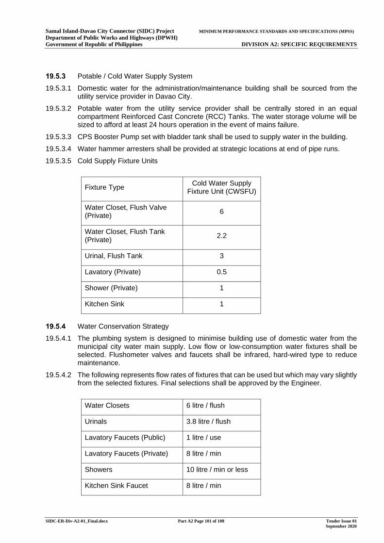
Samal Island-Davao City Connector (SIDC) Project MINIMUM PERFORMANCE STANDARDS AND SPECIFICATIONS (MPSS) Department of Public Works and Highways (DPWH) Government of Republic of Philippines DIVISION A2: SPECIFIC REQUIREMENTS
SIDC-ER-Div-A2-01_Final.docx Part A2 Page 101 of 108 Tender Issue 01 September 2020
Potable / Cold Water Supply System
19.5.3.1 Domestic water for the administration/maintenance building shall be sourced from the utility service provider in Davao City.
19.5.3.2 Potable water from the utility service provider shall be centrally stored in an equal compartment Reinforced Cast Concrete (RCC) Tanks. The water storage volume will be sized to afford at least 24 hours operation in the event of mains failure.
19.5.3.3 CPS Booster Pump set with bladder tank shall be used to supply water in the building.
19.5.3.4 Water hammer arresters shall be provided at strategic locations at end of pipe runs.
19.5.3.5 Cold Supply Fixture Units
Fixture Type Cold Water Supply Fixture Unit (CWSFU)
Water Closet, Flush Valve (Private) 6
Water Closet, Flush Tank (Private) 2.2
Urinal, Flush Tank 3
Lavatory (Private) 0.5
Shower (Private) 1
Kitchen Sink 1
Water Conservation Strategy
19.5.4.1 The plumbing system is designed to minimise building use of domestic water from the municipal city water main supply. Low flow or low-consumption water fixtures shall be selected. Flushometer valves and faucets shall be infrared, hard-wired type to reduce maintenance.
19.5.4.2 The following represents flow rates of fixtures that can be used but which may vary slightly from the selected fixtures. Final selections shall be approved by the Engineer.
Water Closets 6 litre / flush
Urinals 3.8 litre / flush
Lavatory Faucets (Public) 1 litre / use
Lavatory Faucets (Private) 8 litre / min
Showers 10 litre / min or less
Kitchen Sink Faucet 8 litre / min
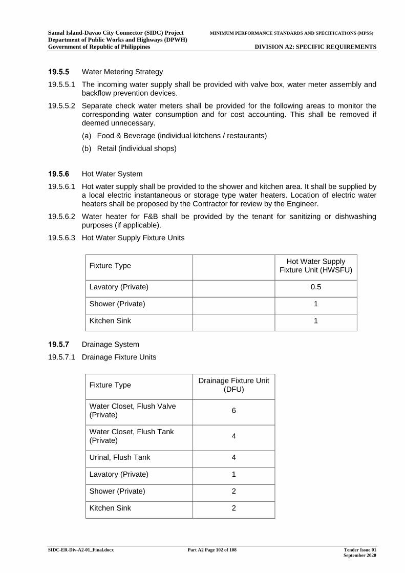
Samal Island-Davao City Connector (SIDC) Project MINIMUM PERFORMANCE STANDARDS AND SPECIFICATIONS (MPSS) Department of Public Works and Highways (DPWH) Government of Republic of Philippines DIVISION A2: SPECIFIC REQUIREMENTS
SIDC-ER-Div-A2-01_Final.docx Part A2 Page 102 of 108 Tender Issue 01 September 2020
Water Metering Strategy
19.5.5.1 The incoming water supply shall be provided with valve box, water meter assembly and backflow prevention devices.
19.5.5.2 Separate check water meters shall be provided for the following areas to monitor the corresponding water consumption and for cost accounting. This shall be removed if deemed unnecessary.
Food & Beverage (individual kitchens / restaurants)
Retail (individual shops)
Hot Water System
19.5.6.1 Hot water supply shall be provided to the shower and kitchen area. It shall be supplied by a local electric instantaneous or storage type water heaters. Location of electric water heaters shall be proposed by the Contractor for review by the Engineer.
19.5.6.2 Water heater for F&B shall be provided by the tenant for sanitizing or dishwashing purposes (if applicable).
19.5.6.3 Hot Water Supply Fixture Units
Fixture Type Hot Water Supply Fixture Unit (HWSFU)
Lavatory (Private) 0.5
Shower (Private) 1
Kitchen Sink 1
Drainage System
19.5.7.1 Drainage Fixture Units
Fixture Type Drainage Fixture Unit (DFU)
Water Closet, Flush Valve (Private)
6
Water Closet, Flush Tank (Private) 4
Urinal, Flush Tank 4
Lavatory (Private) 1
Shower (Private) 2
Kitchen Sink 2
Samal Island-Davao City Connector (SIDC) Project MINIMUM PERFORMANCE STANDARDS AND SPECIFICATIONS (MPSS) Department of Public Works and Highways (DPWH) Government of Republic of Philippines DIVISION A2: SPECIFIC REQUIREMENTS
SIDC-ER-Div-A2-01_Final.docx Part A2 Page 103 of 108 Tender Issue 01 September 2020
19.5.7.2 Rainwater Harvesting. Rainwater collected from the roof shall be stored to a dedicated rainwater harvesting tank. It shall be used for irrigation or for flushing of toilets. The level of treatment of the rainwater prior to reuse shall be agreed with the Engineer.
19.5.7.3 Storm Drainage System. The building storm water drainage shall be provided for collecting rainwater from exposed/open areas then discharging to the site wide storm water drainage system. This includes surface channels, trenches, area drains, catch basins and gullies.
19.5.7.4 The storm drainage shall be collected and connected to the proposed building storm drainage manhole at below Ground Level, and subsequently discharged to the site wide storm drainage system.
19.5.7.5 Sump pit and sump pumps shall be provided to discharge the storm water to the drainage manhole if gravity discharge is not practically feasible. Each sump pit shall have two submersible sump pumps, one duty and one assist.
19.5.7.6 Balcony drains shall be collected and discharged to the storm drainage network.
19.5.7.7 Car park and hard landscaped areas shall be provided with storm water catch basins / kerb gullies. Petrol interceptors shall be specified to intercept oil and fuel spillage from cars within the car parking areas prior to reticulation and discharge to the municipal network.
19.5.7.8 Foul and Wastewater Drainage System. A fully vented combined foul and waste building drainage system shall be provided.
19.5.7.9 Foul and wastewater from the toilet areas, shower and plant room drainage shall be connected to the Sewage Treatment Plant (STP). Location of STP shall be approved by the Engineer. Wastewater in the STP shall be treated to meet the DENR Effluent Standards and be safe for discharge.
19.5.7.10 All sanitary fixtures shall be equipped with anti-siphonage traps. Individual fixtures and major drainage equipment e.g. grease trap, sewer manhole, drainage manhole and sump pit, shall be vented.
19.5.7.11 Acoustic insulation shall be provided for drainage pipework located above ceiling voids of noise sensitive areas such as office, etc.
19.5.7.12 Provisions shall be made for soil, waste and greasy kitchen waste pipework for F&B, Retail & Leasable Space for future fit out by the respective tenants, if deem required.
19.5.7.13 Pipework between outlets and interceptors shall have access points for rodding at every change in direction and at every 15 metres.
19.5.7.14 Kitchen Drainage. Greasy water from the office kitchen or pantry area shall be channelled to an independent kitchen waste pipes before discharging to a local grease trap to prevent solidification of grease within pipework.
19.5.7.15 All commercial kitchens shall have their own under-sink primary screening facilities for grease. This shall be omitted if unnecessary.
19.5.7.16 Condensate Drainage. Where possible, condensate from the air handling units and large recirculating AHU shall be recovered and routed to the Rainwater Tank. Where collection of condensate drain via gravity is not feasible, sump pits with submersible sump pumps shall be proposed to pump the condensate water to the Rainwater Tank.
19.5.7.17 For smaller terminal room units, condensate shall be discharged to the drainage network via the nearest floor drain, as this is expected to be very low.
19.5.7.18 Generator Room and Fuel Tank Wastewater Disposal System. Wastewater from the Genset room and fuel tank shall be collected via oil/petrol interceptors through gravity or sump pump system prior discharging to the site wide wastewater system.
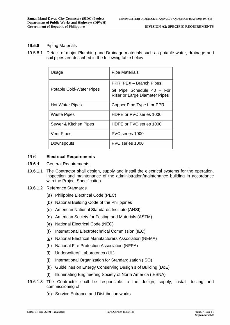
Samal Island-Davao City Connector (SIDC) Project MINIMUM PERFORMANCE STANDARDS AND SPECIFICATIONS (MPSS) Department of Public Works and Highways (DPWH) Government of Republic of Philippines DIVISION A2: SPECIFIC REQUIREMENTS
SIDC-ER-Div-A2-01_Final.docx Part A2 Page 104 of 108 Tender Issue 01 September 2020
Piping Materials
19.5.8.1 Details of major Plumbing and Drainage materials such as potable water, drainage and soil pipes are described in the following table below.
Usage Pipe Materials
Potable Cold-Water Pipes PPR, PEX – Branch Pipes
GI Pipe Schedule 40 – For Riser or Large Diameter Pipes
Hot Water Pipes Copper Pipe Type L or PPR
Waste Pipes HDPE or PVC series 1000
Sewer & Kitchen Pipes HDPE or PVC series 1000
Vent Pipes PVC series 1000
Downspouts PVC series 1000
Electrical Requirements
General Requirements
19.6.1.1 The Contractor shall design, supply and install the electrical systems for the operation, inspection and maintenance of the administration/maintenance building in accordance with the Project Specification.
19.6.1.2 Reference Standards
Philippine Electrical Code (PEC)
National Building Code of the Philippines
American National Standards Institute (ANSI)
American Society for Testing and Materials (ASTM)
National Electrical Code (NEC)
International Electrotechnical Commission (IEC)
National Electrical Manufacturers Association (NEMA)
National Fire Protection Association (NFPA)
Underwriters’ Laboratories (UL)
International Organization for Standardization (ISO)
Guidelines on Energy Conserving Design s of Building (DoE)
Illuminating Engineering Society of North America (IESNA)
19.6.1.3 The Contractor shall be responsible to the design, supply, install, testing and commissioning of:
Service Entrance and Distribution works
Samal Island-Davao City Connector (SIDC) Project MINIMUM PERFORMANCE STANDARDS AND SPECIFICATIONS (MPSS) Department of Public Works and Highways (DPWH) Government of Republic of Philippines DIVISION A2: SPECIFIC REQUIREMENTS
SIDC-ER-Div-A2-01_Final.docx Part A2 Page 105 of 108 Tender Issue 01 September 2020
Lighting and Small Power System
Lightning Protection and Grounding System
Fire Detection and Alarm System
Structured Cabling (Voice and Data) System
Power Supply
19.6.2.1 The administration/maintenance building shall be provided with a complete power supply system connected to the nearest Local Utility Company three-phase power line and electrical sub-station, together with automatic transfer switch, soundproofing, lightning and fire protection system.
19.6.2.2 The Contractor shall be responsible for the early coordination with the Local Utility Company and the Engineer regarding the requirements for the construction of the distribution line and determining the location of the point of connection. The Contractor shall be responsible for providing necessary drawings and documents required by Local Utility Company for the power application.
19.6.2.3 The Contractor shall be responsible for all the costs associated with organising the connection, including any costs associated with upgrading the supply if needed.
Service Entrance
19.6.3.1 The Contractor shall design, install, test and commission a complete Service entrance equipment and protection in accordance with the latest revision of Philippine Electrical Code.
19.6.3.2 The Contractor shall coordinate with Local Utility Company, comply with the guidelines and requirement on provision of the feeder cables, isolations and metering.
19.6.3.3 All necessary protection, foundation and accessories to complete these systems shall be provided by the Contractor in closed coordination with Local Utility Company.
Distribution works
19.6.4.1 All Material and equipment shall be designed, manufactured, tested and installed in accordance with the latest revision of Philippine Electrical Code and/or most recognized international codes and standards.
19.6.4.2 Electrical Distribution Boards shall be equipped with complete protections, power quality metering and locking option. It shall be installed in secured location to avoid any tampering. All Distribution Boards shall be properly labelled and have connection directories.
19.6.4.3 The Contractor shall provide distribution board detail drawing showing connection diagram, ratings and sizes of all components.
19.6.4.4 The Contractor shall provide 25% spare capacity for future expansion.
19.6.4.5 The Contractor shall provide 100% Emergency Back-up power supply including automatic transfer switch, protections, controls and necessary materials in accordance with Local and International codes.
19.6.4.6 All wires and cables shall be an electrical grade and annealed copper fabricated in accordance with ASTM and other international codes.
19.6.4.7 All trays, conduits and fittings shall be UL listed. Cable trays shall be non-corrosive type. Materials shall be hot-dipped galvanised conforming to NEMA classification of loading.
Samal Island-Davao City Connector (SIDC) Project MINIMUM PERFORMANCE STANDARDS AND SPECIFICATIONS (MPSS) Department of Public Works and Highways (DPWH) Government of Republic of Philippines DIVISION A2: SPECIFIC REQUIREMENTS
SIDC-ER-Div-A2-01_Final.docx Part A2 Page 106 of 108 Tender Issue 01 September 2020
Lighting and Small Power System
19.6.5.1 The Contractor shall design the lighting system in accordance with the latest edition of PEC and IESNA.
19.6.5.2 The Contractor shall provide both normal and emergency lighting calculation using latest version Dialux Software.
19.6.5.3 All lighting fixtures shall be LED type. If there is a potential for flammable gas and/or liquid to be present, explosion proof lighting shall be used.
19.6.5.4 Lighting shall be provided at outdoor areas during night time and at indoor areas of the Administration/Maintenance Building.
19.6.5.5 All lighting fixtures shall be in accessible and maintainable manner. Lighting layout shall be coordinated with other trades to avoid clashes and obstructions.
Lightning Protection and Grounding
19.6.6.1 Lightning system shall be conventional type. Structural rebars shall not be allowed to be used as down conductors.
19.6.6.2 All lightning and ground rods including accessories shall be UL listed.
19.6.6.3 The Contractor shall provide a separate grounding for the electrical and clean earth grounding system.
19.6.6.4 Ground test pits shall be provided as per PEC requirement or at every interconnection of ground conductor.
19.6.6.5 The Contractor shall provide grounding calculations for Engineer’s approval.
Fire Detection and Alarm System
19.6.7.1 The Contractor shall design, install, test and commission the FDAS and its peripherals in accordance with PEC and NFPA requirement.
19.6.7.2 Fire alarm equipment shall be addressable type and UL Listed.
19.6.7.3 Fire Alarm control panel (FACP) shall be located in security offices and/or maintenance offices to provide easy monitoring and control of the system.
19.6.7.4 The Contractor shall provide 25% capacity to each circuit loop.
19.6.7.5 The Contractor shall provide battery sizing of the FACP. Battery size shall include a minimum of 20% safety margin.
19.6.7.6 The Contractor shall provide interfacing at any access door controlled by security in order to allow opening of the door in an event of fire.
19.6.7.7 The Contractor shall provide loudspeakers at the exterior area. These shall be strategically located at the premises of Administration/Maintenance Building. All outdoor loudspeakers shall be IP54 as minimum requirement.
19.6.7.8 All wires shall be fire rated compliant to UL2196. Minimum size of conduit shall be 20mm diameter. PVC conduits shall be used only if embedded in concrete. The Contractor shall also provide voltage drop calculation.
19.6.7.9 Fire Detection and Alarm System shall be interface with MVAC. In the event of fire, all MVAC equipment shall be automatically shut-off.

Samal Island-Davao City Connector (SIDC) Project MINIMUM PERFORMANCE STANDARDS AND SPECIFICATIONS (MPSS) Department of Public Works and Highways (DPWH) Government of Republic of Philippines DIVISION A2: SPECIFIC REQUIREMENTS
SIDC-ER-Div-A2-01_Final.docx Part A2 Page 107 of 108 Tender Issue 01 September 2020
Structured Cabling (Voice and Data) System
19.6.8.1 The Contractor shall design, install, test and commission a complete structured cabling system in accordance with ANSI/TIA, IEEE, PEC and other local/international codes and Standards.
19.6.8.2 The Contractor shall be responsible for the early coordination with Local Telecom Company and the Engineer regarding the requirements and determining the location of point connection. The Contractor shall be responsible in providing necessary drawings and documents required by Local Telecom Company for Engineer’s application.
19.6.8.3 The Contractor shall provide a dedicated room for IT cabinets, server racks, MTTC/MDF and IDF. These IT rooms shall be provided with AC units to maintain the required temperature. Adequate space shall be considered in selection of IT rooms.
19.6.8.4 All Backbone, Horizontal and telecommunication cables shall be in accordance with TIA and ISO standards. All cables shall have independent raceways and support.
19.6.8.5 All Voice and Data cables shall be UTP Category 6 cable unless otherwise stated in the approved drawings.
19.6.8.6 All Fiber optic cable shall be multimode and suitable for indoor and outdoor application. The Contractor shall include all necessary materials and terminating kits to complete the system.
19.6.8.7 The Contractor shall provide Category 6 Patch Panel including RJ-45 Cat 6 Patch cords in compliance to TIA and ISO standards.
19.6.8.8 All Conduit, Cable tray, Wireway, Trunking and Raceway shall not exceed 40% fill. Bending radius shall be not more than 90 degrees or as per cable manufacturer recommendation.
19.6.8.9 The Contractor shall provide UPS for server and computer within IT room with minimum back-up time of 5 minutes.
19.6.8.10 The Contractor shall provide a separate grounding for Structured Cabling Equipment.
20 BICYCLE AND PEDESTRIAN FACILITY
The Contractor shall conduct all work necessary to meet the requirements associated with the bicycle and pedestrian facilities for the Project as described in the Highway Design Basis Annex B Division A2 of the Employer’s Requirements and IPIF1/SIDC/DEF/CVL/1202.
The Contractor shall submit their full plans for the work to the Engineer for review and approval by the Employer. The plans shall be consistent with regional bicycle and pedestrian plans, and shall comply with the prevailing best practises and latest relevant design standards and specifications as agreed with the Engineer.
21 PROVISION OF SPECIAL VEHICLES
General Requirements
The design, supply and delivery of the Special Vehicles are provisional items in this contract. The Contractor shall not proceed with the design and procurement until written instruction is received from the Employer or the Engineer. Once confirmed, the Contractor shall supply the special vehicles and training as specified in Specification Part L for operation and maintenance of the link by the Employer.
Samal Island-Davao City Connector (SIDC) Project MINIMUM PERFORMANCE STANDARDS AND SPECIFICATIONS (MPSS) Department of Public Works and Highways (DPWH) Government of Republic of Philippines DIVISION A2: SPECIFIC REQUIREMENTS
SIDC-ER-Div-A2-01_Final.docx Part A2 Page 108 of 108 Tender Issue 01 September 2020
Refer to the Specification Part L for detailed requirements and the number of the Special Vehicle Type A to Type L. Further details about the Type K Under Bridge Inspection Vehicle(s) (UBIV) are given in Article 54.4 of the Specification Part F. UBIV shall be designed specifically to suit the requirement of the SIDC design.
Samal Island-Davao City Connector (SIDC) Project EMPLOYER’S REQUIREMENTS Department of Public Works and Highways (DPWH) Government of Republic of Philippines DIVISION A2 ANNEX B: HIGHWAY DESIGN BASIS
Annex B SIDC Highway Design Basis Tender Issue 1.docx Tender Issue 01 September 2020
MINIMUM PERFORMANCE STANDARDS AND SPECIFICATIONS (MPSS)
(PART OF THE EMPLOYER’S REQUIREMENTS)
DIVISION A2: SPECIFIC REQUIREMENTS
ANNEX B: HIGHWAY DESIGN BASIS
Samal Island-Davao City Connector (SIDC) Project EMPLOYER’S REQUIREMENTS Department of Public Works and Highways (DPWH) Government of Republic of Philippines DIVISION A2 ANNEX B: HIGHWAY DESIGN BASIS
Annex B SIDC Highway Design Basis Tender Issue 1.docx Tender Issue 01 September 2020
MINIMUM PERFORMANCE STANDARDS AND SPECIFICATIONS (MPSS)
DOCUMENT STRUCTURE
DIVISION A1: GENERAL REQUIREMENTS
ANNEX A1 NOT USED
ANNEX A2 CONTRACTOR CERTIFICATES
ANNEX A3 BRIDGE STRUCTURES CERTIFICATION PACKAGES
ANNEX A4 STATUTORY PROCEDURES
ANNEX A5 ENVIRONMENTAL MANAGEMENT AND MONITORING
ANNEX A6 NOT USED
ANNEX A7 NOT USED
ANNEX A8 REINSTATEMENT OF SITE
ANNEX A9 PROGRAMME OF WORKS
ANNEX A10 QUALITY MANAGEMENT SYSTEM
ANNEX A11 SUBSTANCES HAZARDOUS TO HEALTH
DIVISION A2: SPECIFIC REQUIREMENTS
ANNEX B HIGHWAY DESIGN BASIS
ANNEX C STRUCTURAL DESIGN BASIS
ANNEX D GROUND INVESTIGATION SPECIFICATION
ANNEX E ADMINISTRATION BUILDING
DIVISION A3: DRAWINGS
Samal Island-Davao City Connector (SIDC) Project EMPLOYER’S REQUIREMENTS Department of Public Works and Highways (DPWH) Government of Republic of Philippines DIVISION A2 ANNEX B: HIGHWAY DESIGN BASIS
Annex B SIDC Highway Design Basis Tender Issue 1.docx Part A2 Annex B Page i of ii Tender Issue 01 September 2020
EMPLOYER’S REQUIREMENTS
DIVISION A2: SPECIFIC REQUIREMENTS
ANNEX B: HIGHWAY DESIGN BASIS
CONTENTS PAGE
1 GENERAL ......................................................................................................... 1
1.1 Scope ................................................................................................................ 1
2 GENERAL REQUIREMENTS ............................................................................ 1
2.1 Design Standards ............................................................................................ 1
2.2 Design Speed ................................................................................................... 1
2.3 Design Vehicle ................................................................................................. 1
2.4 Road Cross Sections ....................................................................................... 1
2.5 Horizontal and Vertical Alignment .................................................................. 2
2.6 Junctions .......................................................................................................... 3
2.7 Accesses .......................................................................................................... 3
2.8 Highway Drainage ............................................................................................ 3
2.9 Carriageway Tie-ins ......................................................................................... 4
3 SPECIFIC REQUIREMENTS ............................................................................. 4
3.1 Davao ................................................................................................................ 4
3.2 Samal ................................................................................................................ 5

Samal Island-Davao City Connector (SIDC) Project EMPLOYER’S REQUIREMENTS Department of Public Works and Highways (DPWH) Government of Republic of Philippines DIVISION A2 ANNEX B: HIGHWAY DESIGN BASIS
Annex B SIDC Highway Design Basis Tender Issue 1.docx Part A2 Annex B Page ii of ii Tender Issue 01 September 2020
This page is blank
Samal Island-Davao City Connector (SIDC) Project EMPLOYER’S REQUIREMENTS Department of Public Works and Highways (DPWH) Government of Republic of Philippines DIVISION A2 ANNEX B: HIGHWAY DESIGN BASIS
Annex B SIDC Highway Design Basis Tender Issue 1.docx Part A2 Annex B Page i of v Tender Issue 01 September 2020
1 GENERAL
1.1 Scope
This Highway Design Basis states the design requirements and design standards to be used for the highway design of the Samal Island-Davao City Connector (SIDC). It provides details of the implementation of the Philippines and AASHTO standards for the project and complementary information related to the design of the SIDC. Additional standards and specifications required for the design are presented in the corresponding sections.
The Contractor shall undertake detailed design for the roads as shown in Drawing nos. IPIF1/SIDC/DEF/CVL/1201 – 1208 in accordance with the requirements set out in this Annex.
All aspects of this Highway Design Basis are mandatory.
2 GENERAL REQUIREMENTS
2.1 Design Standards
The design of the highways shall be in accordance with the following standards unless otherwise stated in this Annex:
(i) Design Guidelines, Criteria and Standards 2015 by DPWH (referred as DGCS hereafter), including but not limited to Volume 4 Highway Design
(ii) Highway Safety Design Standards 2012 by DPWH
(iii) DPWH Departmental Orders
In the absence of certain design criteria in the above standards, the following standards shall be followed for such design criteria unless otherwise stated in this Annex:
(iv) A Policy on Geometric Design of Highways and Streets 2011 6th Edition by AASHTO (referred as AASHTO 2011 hereafter)
(v) Roadside Design Guide 2011 4th Edition by AASHTO (referred as AASHTO RDG hereafter)
Refer to Division A2 Section 1.3 for general requirements on the use of the design standard.
2.2 Design Speed
The design speed to be adopted for the purpose of alignment design shall be 80kph for the mainline, and 40kph for all other roads and junctions.
2.3 Design Vehicle
Design vehicle shall be WB-19 in accordance with AASHTO 2011.
2.4 Road Cross Sections
The road configuration cross sections shall be as shown in Drawing nos. IPIF1/SIDC/DEF/CVL/1101 – 1103. Allowance shall be made for widening on curves, widening for visibility or for accommodating junction requirements.
Sidewalk, sidewalk/ cycleway and utilities corridor shall be as specified in Drawing nos. IPIF1/SIDC/DEF/CVL/1101 – 1103. The exact extent and details shall be coordinated with the Employer.
The Contractor shall refer to Division A2 Section 7 for the requirements on road restraint systems and allow sufficient space including the corresponding horizontal clearance required for such provision.
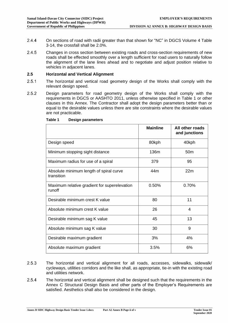
Samal Island-Davao City Connector (SIDC) Project EMPLOYER’S REQUIREMENTS Department of Public Works and Highways (DPWH) Government of Republic of Philippines DIVISION A2 ANNEX B: HIGHWAY DESIGN BASIS
Annex B SIDC Highway Design Basis Tender Issue 1.docx Part A2 Annex B Page ii of v Tender Issue 01 September 2020
On sections of road with radii greater than that shown for “NC” in DGCS Volume 4 Table 3-14, the crossfall shall be 2.0%.
Changes in cross section between existing roads and cross-section requirements of new roads shall be effected smoothly over a length sufficient for road users to naturally follow the alignment of the lane lines ahead and to negotiate and adjust position relative to vehicles in adjacent lanes.
2.5 Horizontal and Vertical Alignment
The horizontal and vertical road geometry design of the Works shall comply with the relevant design speed.
Design parameters for road geometry design of the Works shall comply with the requirements in DGCS or AASHTO 2011, unless otherwise specified in Table 1 or other clauses in this Annex. The Contractor shall adopt the design parameters better than or equal to the desirable values unless there are site constraints where the desirable values are not practicable.
Table 1 Design parameters
Mainline All other roads and junctions
Design speed 80kph 40kph
Minimum stopping sight distance 136m 50m
Maximum radius for use of a spiral 379 95
Absolute minimum length of spiral curve transition
44m 22m
Maximum relative gradient for superelevation runoff
0.50% 0.70%
Desirable minimum crest K value 80 11
Absolute minimum crest K value 26 4
Desirable minimum sag K value 45 13
Absolute minimum sag K value 30 9
Desirable maximum gradient 3% 4%
Absolute maximum gradient 3.5% 6%
The horizontal and vertical alignment for all roads, accesses, sidewalks, sidewalk/ cycleways, utilities corridors and the like shall, as appropriate, tie-in with the existing road and utilities network.
The horizontal and vertical alignment shall be designed such that the requirements in the Annex C Structural Design Basis and other parts of the Employer’s Requirements are satisfied. Aesthetics shall also be considered in the design.
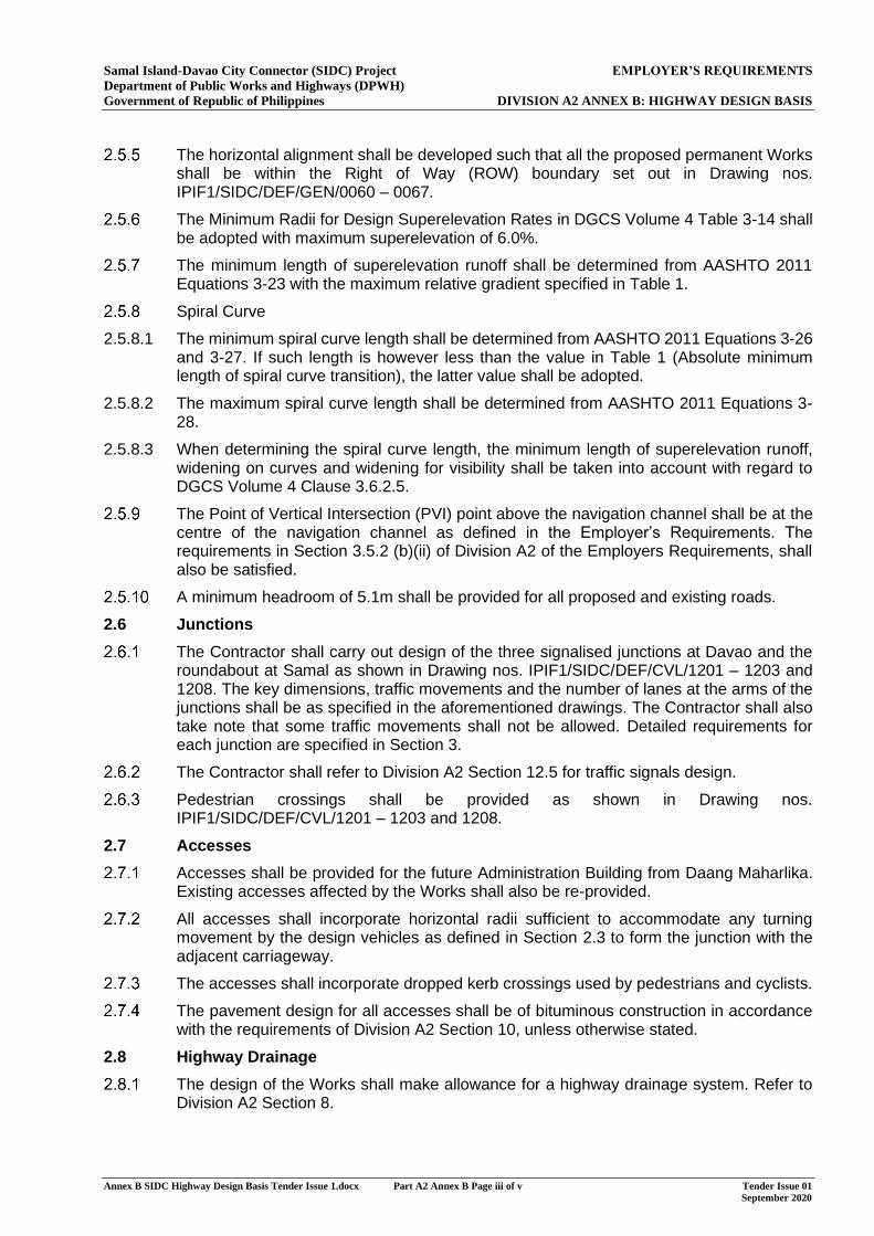
Samal Island-Davao City Connector (SIDC) Project EMPLOYER’S REQUIREMENTS Department of Public Works and Highways (DPWH) Government of Republic of Philippines DIVISION A2 ANNEX B: HIGHWAY DESIGN BASIS
Annex B SIDC Highway Design Basis Tender Issue 1.docx Part A2 Annex B Page iii of v Tender Issue 01 September 2020
The horizontal alignment shall be developed such that all the proposed permanent Works shall be within the Right of Way (ROW) boundary set out in Drawing nos. IPIF1/SIDC/DEF/GEN/0060 – 0067.
The Minimum Radii for Design Superelevation Rates in DGCS Volume 4 Table 3-14 shall be adopted with maximum superelevation of 6.0%.
The minimum length of superelevation runoff shall be determined from AASHTO 2011 Equations 3-23 with the maximum relative gradient specified in Table 1.
Spiral Curve
2.5.8.1 The minimum spiral curve length shall be determined from AASHTO 2011 Equations 3-26 and 3-27. If such length is however less than the value in Table 1 (Absolute minimum length of spiral curve transition), the latter value shall be adopted.
2.5.8.2 The maximum spiral curve length shall be determined from AASHTO 2011 Equations 3-28.
2.5.8.3 When determining the spiral curve length, the minimum length of superelevation runoff, widening on curves and widening for visibility shall be taken into account with regard to DGCS Volume 4 Clause 3.6.2.5.
The Point of Vertical Intersection (PVI) point above the navigation channel shall be at the centre of the navigation channel as defined in the Employer’s Requirements. The requirements in Section 3.5.2 (b)(ii) of Division A2 of the Employers Requirements, shall also be satisfied.
A minimum headroom of 5.1m shall be provided for all proposed and existing roads.
2.6 Junctions
The Contractor shall carry out design of the three signalised junctions at Davao and the roundabout at Samal as shown in Drawing nos. IPIF1/SIDC/DEF/CVL/1201 – 1203 and 1208. The key dimensions, traffic movements and the number of lanes at the arms of the junctions shall be as specified in the aforementioned drawings. The Contractor shall also take note that some traffic movements shall not be allowed. Detailed requirements for each junction are specified in Section 3.
The Contractor shall refer to Division A2 Section 12.5 for traffic signals design.
Pedestrian crossings shall be provided as shown in Drawing nos. IPIF1/SIDC/DEF/CVL/1201 – 1203 and 1208.
2.7 Accesses
Accesses shall be provided for the future Administration Building from Daang Maharlika. Existing accesses affected by the Works shall also be re-provided.
All accesses shall incorporate horizontal radii sufficient to accommodate any turning movement by the design vehicles as defined in Section 2.3 to form the junction with the adjacent carriageway.
The accesses shall incorporate dropped kerb crossings used by pedestrians and cyclists.
The pavement design for all accesses shall be of bituminous construction in accordance with the requirements of Division A2 Section 10, unless otherwise stated.
2.8 Highway Drainage
The design of the Works shall make allowance for a highway drainage system. Refer to Division A2 Section 8.
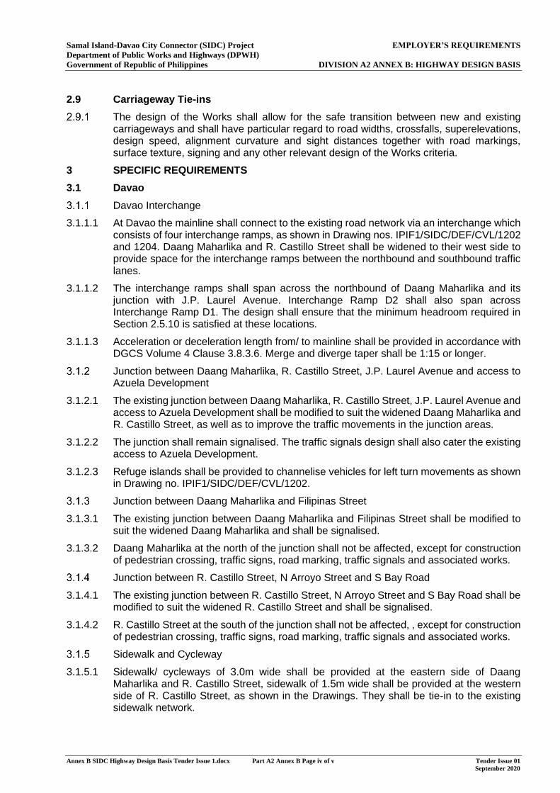
Samal Island-Davao City Connector (SIDC) Project EMPLOYER’S REQUIREMENTS Department of Public Works and Highways (DPWH) Government of Republic of Philippines DIVISION A2 ANNEX B: HIGHWAY DESIGN BASIS
Annex B SIDC Highway Design Basis Tender Issue 1.docx Part A2 Annex B Page iv of v Tender Issue 01 September 2020
2.9 Carriageway Tie-ins
The design of the Works shall allow for the safe transition between new and existing carriageways and shall have particular regard to road widths, crossfalls, superelevations, design speed, alignment curvature and sight distances together with road markings, surface texture, signing and any other relevant design of the Works criteria.
3 SPECIFIC REQUIREMENTS
3.1 Davao
Davao Interchange
3.1.1.1 At Davao the mainline shall connect to the existing road network via an interchange which consists of four interchange ramps, as shown in Drawing nos. IPIF1/SIDC/DEF/CVL/1202 and 1204. Daang Maharlika and R. Castillo Street shall be widened to their west side to provide space for the interchange ramps between the northbound and southbound traffic lanes.
3.1.1.2 The interchange ramps shall span across the northbound of Daang Maharlika and its junction with J.P. Laurel Avenue. Interchange Ramp D2 shall also span across Interchange Ramp D1. The design shall ensure that the minimum headroom required in Section 2.5.10 is satisfied at these locations.
3.1.1.3 Acceleration or deceleration length from/ to mainline shall be provided in accordance with DGCS Volume 4 Clause 3.8.3.6. Merge and diverge taper shall be 1:15 or longer.
Junction between Daang Maharlika, R. Castillo Street, J.P. Laurel Avenue and access to Azuela Development
3.1.2.1 The existing junction between Daang Maharlika, R. Castillo Street, J.P. Laurel Avenue and access to Azuela Development shall be modified to suit the widened Daang Maharlika and R. Castillo Street, as well as to improve the traffic movements in the junction areas.
3.1.2.2 The junction shall remain signalised. The traffic signals design shall also cater the existing access to Azuela Development.
3.1.2.3 Refuge islands shall be provided to channelise vehicles for left turn movements as shown in Drawing no. IPIF1/SIDC/DEF/CVL/1202.
Junction between Daang Maharlika and Filipinas Street
3.1.3.1 The existing junction between Daang Maharlika and Filipinas Street shall be modified to suit the widened Daang Maharlika and shall be signalised.
3.1.3.2 Daang Maharlika at the north of the junction shall not be affected, except for construction of pedestrian crossing, traffic signs, road marking, traffic signals and associated works.
Junction between R. Castillo Street, N Arroyo Street and S Bay Road
3.1.4.1 The existing junction between R. Castillo Street, N Arroyo Street and S Bay Road shall be modified to suit the widened R. Castillo Street and shall be signalised.
3.1.4.2 R. Castillo Street at the south of the junction shall not be affected, , except for construction of pedestrian crossing, traffic signs, road marking, traffic signals and associated works.
Sidewalk and Cycleway
3.1.5.1 Sidewalk/ cycleways of 3.0m wide shall be provided at the eastern side of Daang Maharlika and R. Castillo Street, sidewalk of 1.5m wide shall be provided at the western side of R. Castillo Street, as shown in the Drawings. They shall be tie-in to the existing sidewalk network.
Samal Island-Davao City Connector (SIDC) Project EMPLOYER’S REQUIREMENTS Department of Public Works and Highways (DPWH) Government of Republic of Philippines DIVISION A2 ANNEX B: HIGHWAY DESIGN BASIS
Annex B SIDC Highway Design Basis Tender Issue 1.docx Part A2 Annex B Page v of v Tender Issue 01 September 2020
3.1.5.2 A pedestrian access shall be provided between the sidewalk/ cycleways at Daang Maharlika and the sidewalk at Interchange Ramp D1. Such access shall be in the form of a staircase with 1.2m clear width, with a bicycle gutter alongside for cyclists to wheel their bicycles. The staircase and associated structure shall be within the ROW boundary.
3.1.5.3 A maintenance access shall be provided between the sidewalk/ cycleways at Daang Maharlika and the utilities corridor at Interchange Ramp D4. Such access shall be in the form of a staircase with 0.6m clear width. The staircase and associated structure shall be within the ROW boundary.
3.2 Samal
Roundabout
3.2.1.1 At Samal the mainline shall connect to the Circumferential Road via a roundabout, as shown in Drawing no. IPIF1/SIDC/DEF/CVL/1208.
3.2.1.2 Kerbed traffic deflection islands shall be provided at each arm of the roundabout.
Circumferential Road
3.2.2.1 The existing Circumferential Road is a single 2-lane road but will be upgraded to a single 4-lane road by others. Therefore the two exits of the roundabout connecting existing Circumferential Road shall be single 4-lane as shown in Drawing no. IPIF1/SIDC/DEF/CVL/1103. They shall then be tapered down to match the existing road.
Samal Island-Davao City Connector (SIDC) Project MINIMUM PERFORMANCE STANDARDS AND SPECIFICATIONS (MPSS) Department of Public Works and Highways (DPWH) Government of Republic of Philippines DIVISION A2 - ANNEX C: STRUCTURAL DESIGN BASIS
Annex C SIDC Structural Design Basis Tender Issue 1_final.docx Issue 1 September 2020
MINIMUM PERFORMANCE STANDARDS AND SPECIFICATIONS (MPSS)
(PART OF THE EMPLOYER’S REQUIREMENTS)
DIVISION A2: SPECIFIC REQUIREMENTS
ANNEX C: STRUCTURAL DESIGN BASIS
Samal Island-Davao City Connector (SIDC) Project MINIMUM PERFORMANCE STANDARDS AND SPECIFICATIONS (MPSS) Department of Public Works and Highways (DPWH) Government of Republic of Philippines DIVISION A2 - ANNEX C: STRUCTURAL DESIGN BASIS
Annex C SIDC Structural Design Basis Tender Issue 1_final.docx Issue 1 September 2020
MINIMUM PERFORMANCE STANDARDS AND SPECIFICATIONS (MPSS)
DOCUMENT STRUCTURE
DIVISION A1: GENERAL REQUIREMENTS
ANNEX A1 NOT USED
ANNEX A2 CONTRACTOR CERTIFICATES
ANNEX A3 BRIDGE STRUCTURES CERTIFICATION PACKAGES
ANNEX A4 STATUTORY PROCEDURES
ANNEX A5 ENVIRONMENTAL MANAGEMENT AND MONITORING
ANNEX A6 NOT USED
ANNEX A7 NOT USED
ANNEX A8 REINSTATEMENT OF SITE
ANNEX A9 PROGRAMME OF WORKS
ANNEX A10 QUALITY MANAGEMENT SYSTEM
ANNEX A11 SUBSTANCES HAZARDOUS TO HEALTH
DIVISION A2: SPECIFIC REQUIREMENTS
ANNEX B HIGHWAY DESIGN BASIS
ANNEX C STRUCTURAL DESIGN BASIS
ANNEX D GROUND INVESTIGATION SPECIFICATION
ANNEX E ADMINISTRATION BUILDING
DIVISION A3: DRAWINGS
Samal Island-Davao City Connector (SIDC) Project MINIMUM PERFORMANCE STANDARDS AND SPECIFICATIONS (MPSS) Department of Public Works and Highways (DPWH) Government of Republic of Philippines DIVISION A2 - ANNEX C: STRUCTURAL DESIGN BASIS
Annex C SIDC Structural Design Basis Tender Issue 1_final.docxDivision A2 Annex C Page i of iii Tender Issue 1 September 2020
EMPLOYER’S REQUIREMENTS
DIVISION A2: SPECIFIC REQUIREMENTS
ANNEX C: STRUCTURAL DESIGN BASIS
CONTENTS PAGE
1 Introduction 1
1.1 Scope 1
2 Functional requirements 2
2.1 Highway Carriageway 2
2.2 Pedestrian access Footpaths/Cycleway 3
2.3 Utilities Corridor and Maintenance Access 3
2.4 Navigation Requirements 3
2.5 Environmental & Sustainability 4
2.6 Durability 5
2.7 Operation and Maintenance 9
2.8 Utility Provisions 9
3 Structural Design - General 10
3.1 Design Standards 10
3.2 Design Limit States 11
3.3 Disproportionate Damage 11
3.4 Design Working Life 11
3.5 The minimum Design Life 11
3.6 Design Load Factors and Combinations 12
4 Design Loading 18
5 Reinforced Concrete and Prestressed Concrete Design 31
5.1 Structural Analysis 31
5.2 Materials 31
5.3 Service Limit State Check 31
5.4 Fatigue Limit State Check 32
5.5 Strength Limit State Check 32
5.6 Extreme Event Limit State Check 32
5.7 Reinforcement Detailing 32
5.8 Durability 32
6 Steel and Composite steel and Concrete Structure Design 33
6.1 General 33
6.2 Structural Analysis 33
6.3 Materials 33
6.4 Limit States 33
6.5 Stay Cables 33
Samal Island-Davao City Connector (SIDC) Project MINIMUM PERFORMANCE STANDARDS AND SPECIFICATIONS (MPSS) Department of Public Works and Highways (DPWH) Government of Republic of Philippines DIVISION A2 - ANNEX C: STRUCTURAL DESIGN BASIS
Annex C SIDC Structural Design Basis Tender Issue 1_final.docxDivision A2 Annex C Page ii of iii Tender Issue 1 September 2020
CONTENTS PAGE
6.6 Negative Support Reaction and Tie Down Cable 34
7 Seismic Design Criteria 35
7.1 General 35
7.2 Design Standards 35
7.3 Seismic Design Philosophy 35
7.4 Bridge Operational Classification 35
7.5 Seismic Performance Requirements and Design Earthquake Levels 36
7.6 Seismic Action 36
7.7 Seismic Event During Construction 38
7.8 Analysis Requirements 38
7.9 Structural Design Requirements 39
7.10 Performance-based design approach 39
7.11 Spatial Variability of Ground Motion 40
7.12 Foundations 40
7.13 Minimum Seat Length Requirements 40
7.14 Longitudinal Restrainers (Unseating Prevention Device) 41
7.15 Hold-Down Devices 41
7.16 Bearing support system 41
7.17 Gap between adjacent bridge girders and substructures 41
8 Geotechnical design 42
8.1 General 42
8.2 Ground Investigation 42
8.3 Engineering Geology and GeoHazard Assessment 42
8.4 Earthworks 43
8.5 Foundation 45
8.6 Ground Improvement 51
8.7 Instrumentation & Monitoring 52
9 Design of ancillary works 53
9.1 Movement Joints and Structural Bearings 53
9.2 Inspection Stairs, Walkways, Ladders and Platforms 53
9.3 Vehicle Restraint System and Parapets 53
9.4 Deck Waterproofing and Surfacing 53

Samal Island-Davao City Connector (SIDC) Project MINIMUM PERFORMANCE STANDARDS AND SPECIFICATIONS (MPSS) Department of Public Works and Highways (DPWH) Government of Republic of Philippines DIVISION A2 - ANNEX C: STRUCTURAL DESIGN BASIS
Annex C SIDC Structural Design Basis Tender Issue 1_final.docxDivision A2 Annex C Page iii of iii Tender Issue 1 September 2020
This page is blank
Samal Island-Davao City Connector (SIDC) Project MINIMUM PERFORMANCE STANDARDS AND SPECIFICATIONS (MPSS) Department of Public Works and Highways (DPWH) Government of Republic of Philippines DIVISION A2 - ANNEX C: STRUCTURAL DESIGN BASIS
Annex C SIDC Structural Design Basis Tender Issue 1_final.docx Division A2 Annex C Page 1 of 55 Tender Issue 1 September 2020
1 INTRODUCTION
1.1 Scope
1.1.1 This Structural Design Basis states the design requirements and design standards to be used for the structural design of the Samal Island – Davao City (SIDC) Connector Bridge Project - Detailed Engineering Design (DED). It provides details of the implementation of the standards published by Department of Public Works and Highways in the Philippines and provides complementary information related to the design requirements for SIDC. Additional standards and design specifications required to be used for the DED are given in the relevant sections.
1.1.2 All aspects of this Structural Design Basis are mandatory.
1.1.3 The Contractor shall prepare a Structures Design Statement as indicated in Section 16.8 of ER Division A1.
Samal Island-Davao City Connector (SIDC) Project MINIMUM PERFORMANCE STANDARDS AND SPECIFICATIONS (MPSS) Department of Public Works and Highways (DPWH) Government of Republic of Philippines DIVISION A2 - ANNEX C: STRUCTURAL DESIGN BASIS
Annex C SIDC Structural Design Basis Tender Issue 1_final.docx Division A2 Annex C Page 2 of 55 Tender Issue 1 September 2020
2 FUNCTIONAL REQUIREMENTS
2.1 Highway Carriageway
2.1.1 General
2.1.1.1 The Bridge Structures functional cross section shall be as defined in the Employer’s Requirements Division A2.
2.1.2 Road Design Parameters
2.1.2.1 The design of the highways shall be in accordance with the design requirements set out in Division A2 of the Employer’s Requirements.
2.1.3 Highway Alignment
2.1.3.1 The bridge shall be set out in relation to the project highway alignment. The alignment design requirements are set out in Division A2 and Annex B of the Employer’s Requirements.
2.1.4 Traffic Lanes and Clearances
2.1.4.1 The widths of carriageways, traffic lanes, hard shoulders and marginal strips shall be as set out in Annex B of the Employer’s Requirements and on the Drawings.
2.1.4.2 The minimum headroom over the width between the outer edges of the structure free zones shall be as given in Annex B of the Employer’s Requirements, measured perpendicular to the carriageway surface.
2.1.5 Road Design Speed
2.1.5.1 The highway shall have design speed as set out in Annex B of the Employer’s Requirements.
2.1.6 Cross Falls
2.1.6.1 Under permanent loading, both carriageways shall have a nominal cross fall as set out in Annex B of the Employer’s Requirements.
2.1.7 Vehicle Restraint Systems
2.1.7.1 Vehicle restraint system shall be provided as set out in Section 7 of Division A2 of the Employer’s Requirements and as shown on the Drawings.
2.1.8 Highway Road Lighting Installation
2.1.8.1 Refer to the Employers’ Requirements Division A2 and Specification for details and requirements.
2.1.9 Other ancillary items
2.1.9.1 Other ancillary items required to be installed on the bridge structures shall include, but not be limited to, the following:
(a) Traffic signs,
(b) Provisions for Close Circuit Television (CCTV) and speed enforcement cameras,
(c) Deck cell lighting, electrical installation and cable trays,
(d) Overhead sign gantries, and
(e) Other items as specified in the Employer’s Requirements.
2.1.9.2 Refer to the relevant Division of Employer’s Requirements for details and requirements of these items.
Samal Island-Davao City Connector (SIDC) Project MINIMUM PERFORMANCE STANDARDS AND SPECIFICATIONS (MPSS) Department of Public Works and Highways (DPWH) Government of Republic of Philippines DIVISION A2 - ANNEX C: STRUCTURAL DESIGN BASIS
Annex C SIDC Structural Design Basis Tender Issue 1_final.docx Division A2 Annex C Page 3 of 55 Tender Issue 1 September 2020
2.1.9.3 The design of the Works shall make allowance for these items in terms of geometry, loading, power supply and communications.
2.1.10 Highway drainage
2.1.10.1 The design of the Works shall make allowance for a highway drainage system. Refer to Section 8 of Division A2 of the Employer’s Requirements.
2.2 Pedestrian access Footpaths/Cycleway
2.2.1 General
2.2.1.1 The design of the works shall make allowance for the pedestrian access Footpaths/Cycleway. The geometry shall be as set out in Division A2 Specific Requirements and Annex B of the Employer’s Requirements and on the Drawings.
2.2.2 Cross Falls
2.2.2.1 The Footpaths shall have a nominal cross fall as set out in Annex B of the Employer’s Requirements.
2.2.3 Pedestrian Railings
2.2.3.1 Pedestrian railings as part of the Road Restraint System shall be provided as set out in Section 7 of Division A2 of the Employer’s Requirements and as shown on the Drawings
2.3 Utilities Corridor and Maintenance Access
2.3.1 General
2.3.1.1 The design of the works shall make allowance for the utilities corridor. The geometry shall be as set out in Division A2 and Annex B of the Employer’s Requirements and on the Drawings. Maintenance access along the utilities corridor shall be provided.
2.3.2 Cross Falls
2.3.2.1 The nearside maintenance access shall have a nominal cross fall as set out in Annex B of the Employer’s Requirements.
2.3.3 Railings
2.3.3.1 Railings as part of the Road Restraint System shall be provided as set out in Section 7 of Division A2 of the Employer’s Requirements and as shown on the Drawings.
2.4 Navigation Requirements
2.4.1 General
2.4.1.1 The Philippine Coast Guard (PCG) is the authority with overall responsibility for marine safety, and approval of the navigation clearances for new structures over navigable waters. Navigation clearance study was carried out during the Feasibility Study and the navigation clearance specified in this contract was agreed with the authority and shall not be modified.
2.4.2 Design Water Levels
2.4.2.1 The existing water levels are summarised below.