Embed Size (px)
Citation preview

Technical Publication – TP 13
SAM – Functional Hazard Identification EUROCONTROL’s Guidance Material for the application of SAM-FHA

Foreword The purpose of this guidance material is to support the implementation of Functional Hazard Assessment (FHA), one of the three phases of EUROCONTROL’s Safety Assessment Methodology (SAM), which is one of the Acceptable Means of Compliance for the regulatory requirements on risk assessment and mitigation. This document, taken from EUROCONTROL, covers the 5 steps of FHA, with all the corresponding guidance material made available by EUROCONTROL. This guidance material is part of a group of documents which aim at supporting the Air Navigation Service Providers (ANSPs) in fully and effectively applying the SAM Methodology when conducting risk assessments and mitigation with respect to changes to ATM systems. This group of documents consists of four Guidance Materials concerning SAM: an introductory material which explains the fundamental concepts of SAM, namely CAAK TP-12 and three supplementary guidance materials which address the three phases of SAM (FHA, PSSA and SSA), CAAK TP-13, TP-14 and TP-15 respectively. CAAK considers that making this material available to the ANSPs in the Republic of Kosovo will contribute to the safety of air traffic in the Republic of Kosovo, by ensuring that ANSPs have the all the necessary support and guidance in properly addressing safety-related changes to ATM systems. This Guidance Material should be applied taking into consideration the complementary Guidance Materials available for SAM, as well as ANSPs’ own Safety Management Manuals. Furthermore, the content of this Guidance Material broadly addresses subject matter related to risk assessment and mitigation, therefore ANSPs should apply caution when using this material, since it is their responsibility to determine the exact requirements deriving from the Common Requirements and not simply refer to the guidance offered in this publication. ANSP’s must also ensure that when used, this Guidance Material must be suitably adapted to the particular change. Dritan Gjonbalaj Director General Civil Aviation Authority

Functional Hazard Assessment SAF.ET1.ST03.1000-MAN-01-01-00
Edition: 2.0 Released Issue Page I - 1
Safety Assessment Methodology
PART I
FUNCTIONAL HAZARD ASSESSMENT
FUNCTIONALHAZARD
ASSESSMENT
PRELIMINARYSYSTEM SAFETY
ASSESSMENT
SYSTEMSAFETY
ASSESSMENT

Functional Hazard Assessment SAF.ET1.ST03.1000-MAN-01-01-00
Edition: 2.0 Released Issue Page I - 2
This page is intentionally left blank.

Functional Hazard Assessment SAF.ET1.ST03.1000-MAN-01-01-00
Edition: 2.0 Released Issue Page I - 3
TABLE OF CONTENTS
INTRODUCTION
1 OBJECTIVE OF FHA .................................................................................... I-6
2 WHEN AND HOW FHA IS APPLIED............................................................ I-7
3 STRUCTURE OF THE FHA DESCRIPTION ................................................ I-7
4 STRUCTURE OF THIS DOCUMENT ........................................................... I-8
5 READERSHIP TABLE .................................................................................. I-8
6 CONFIGURATION MANAGEMENT, DOCUMENTATION AND RECORDS I-9
6.1 WHY? ............................................................................................................ I-9
6.2 HOW? .......................................................................................................... I-10

Functional Hazard Assessment SAF.ET1.ST03.1000-MAN-01-01-00
Edition: 2.0 Released Issue Page I - 4
CHAPTER 1 - FHA INITIATION
1 OBJECTIVE ................................................................................................. I-13
2 INPUT .......................................................................................................... I-13 • 2.1 System Description ......................................................................................... I-13 • 2.2 Operational Environment Description ........................................................... I-14 • 2.3 Regulatory Framework ................................................................................... I-14 • 2.4 Applicable Standards ...................................................................................... I-14 • 2.5 Other Inputs ..................................................................................................... I-14
3 MAJOR TASKS ........................................................................................... I-15
4 OUTPUT ...................................................................................................... I-15
CHAPTER 2 - FHA SAFETY PLANNING
1 OBJECTIVE ................................................................................................. I-17
2 INPUT .......................................................................................................... I-17
3 MAJOR TASKS ........................................................................................... I-17
4 OUTPUT ...................................................................................................... I-18
CHAPTER 3 – SAFETY OBJECTIVES SPECIFICATION
1 OBJECTIVE ................................................................................................. I-19
2 INPUT .......................................................................................................... I-20
3 MAJOR TASKS ........................................................................................... I-20 3.1 Identify Potential Hazards ............................................................................... I-22 3.2 Identify Hazard Effects .................................................................................... I-23 3.3 Assess Hazard Effects Severity ..................................................................... I-24 3.4 Specify Safety Objectives ............................................................................... I-24 3.5 Assess the intended aggregated risk ............................................................ I-25
4 OUTPUT ...................................................................................................... I-26

Functional Hazard Assessment SAF.ET1.ST03.1000-MAN-01-01-00
Edition: 2.0 Released Issue Page I - 5
CHAPTER 4 - FHA EVALUATION
1 OBJECTIVE ................................................................................................. I-27
2 INPUT .......................................................................................................... I-29
3 MAJOR TASKS ........................................................................................... I-29 • 3.1 FHA Verification tasks .................................................................................... I-30 • 3.2 FHA Validation tasks ....................................................................................... I-30 • 3.3 FHA Process Assurance ................................................................................. I-31
4 OUTPUT ...................................................................................................... I-31
CHAPTER 5 - FHA COMPLETION
1 OBJECTIVE ................................................................................................. I-33
2 INPUT .......................................................................................................... I-33
3 MAJOR TASKS ........................................................................................... I-33
4 OUTPUT ...................................................................................................... I-34

Functional Hazard Assessment SAF.ET1.ST03.1000-MAN-01-01-00
Edition: 2.0 Released Issue Page I - 6
INTRODUCTION
1 OBJECTIVE OF FHA
Functional Hazard Assessment (FHA) is a top-down iterative process, initiated at the beginning of the development or modification of an Air Navigation System. The objective of the FHA process is to determine: how safe does the system need to be.
The process identifies potential failures modes and hazards. It assesses the consequences of their occurrences on the safety of operations, including aircraft operations, within a specified operational environment.
The FHA process specifies overall Safety Objectives of the system, i.e. specifies the safety level to be achieved by the system.
Functional Hazard Assessment SAF.ET1.ST03.1000-MAN-01-01-00
Edition: 2.0 Released Issue Page I - 7
2 WHEN AND HOW FHA IS APPLIED
The essential pre-requisite for conducting an FHA is a description of the high level functions of the system – such as would typically be specified in an operational concept document.
FHA is therefore first conducted during the System Definition phase of the system life cycle.
The purposes of the System Definition phase are to establish basic operational objectives for the system within its specified operational environment, to identify the functions required to achieve these objectives, and to specify system and interfaces (between functions and with the environment) requirements.
FHA is performed before the functions have been allocated to equipment, procedures or people elements: it considers what the proposed system will do, rather than how these elements should implement the functions. Indeed, FHA results will be used to support the process of function allocation.
In practice, however, development and assessment usually proceed in parallel, and some allocation of functions may already have been determined by practical constraints – especially where an existing system is being modified.
FHA can be applied at different levels. Ideally, FHA should be done at the overall Air Navigation Service or System level so that Safety Objectives are specified at this ANS level. Ideally Safety Requirements should be derived on sub-system elements during PSSA of this overall Air Navigation Service or System. So ideally there should be no need for FHA at sub-system level.
However, as of today, FHA is generally done at sub-system level and not at ANS level. Consequently, this methodology provides Guidance Material which addresses both ways of applying it.
FHA is an iterative process, which should be reviewed, revised and refined to cover lower level functions as the allocation of function is decided and the system design evolves.
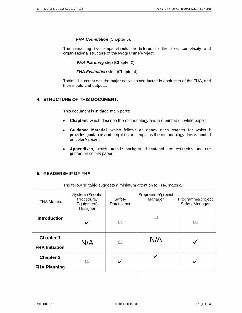
3 STRUCTURE OF THE FHA DESCRIPTION
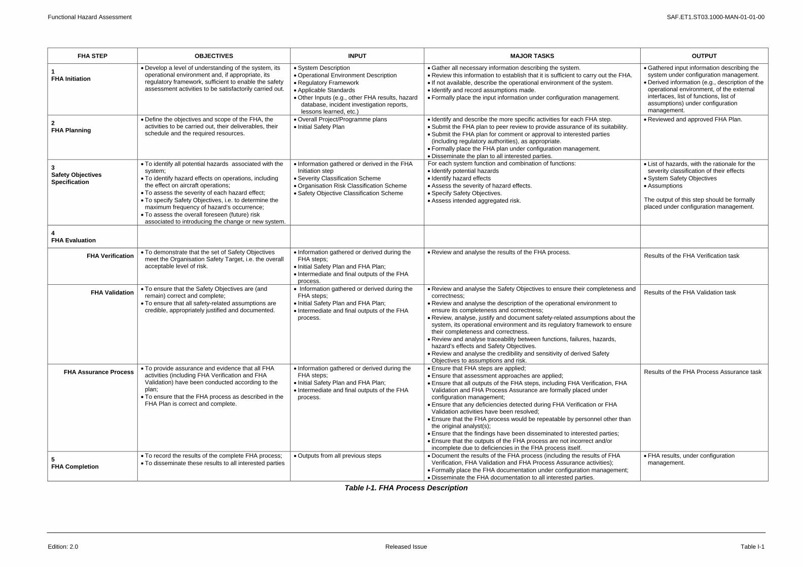
The structure adopted for the description of the FHA process is illustrated in Figure I-1 and Table I-1 in this chapter.
There are three key steps that have to be conducted whatever the size, complexity or organisational structure of the Programme/Project:
FHA Initiation (Chapter 1);
Specification of Safety Objectives (Chapter 3);
Functional Hazard Assessment SAF.ET1.ST03.1000-MAN-01-01-00
Edition: 2.0 Released Issue Page I - 8
FHA Completion (Chapter 5).
The remaining two steps should be tailored to the size, complexity and organisational structure of the Programme/Project:
FHA Planning step (Chapter 2);
FHA Evaluation step (Chapter 4).
Table I-1 summarises the major activities conducted in each step of the FHA, and their inputs and outputs.
4. STRUCTURE OF THIS DOCUMENT.
This document is in three main parts;
• Chapters, which describe the methodology and are printed on white paper;
• Guidance Material, which follows as annex each chapter for which it provides guidance and amplifies and explains the methodology, this is printed on colorA paper;
• Appendixes, which provide background material and examples and are printed on colorB paper.
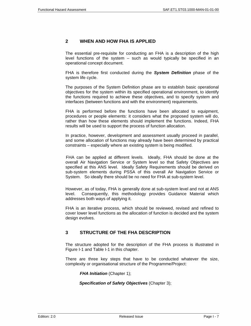
5. READERSHIP OF FHA
The following table suggests a minimum attention to FHA material:
FHA Material
System (People, Procedure, Equipment)
Designer
Safety Practitioner
Programme/project Manager Programme/project
Safety Manager
Introduction
Chapter 1
FHA Initiation N/A N/A
Chapter 2
FHA Planning

Functional Hazard Assessment SAF.ET1.ST03.1000-MAN-01-01-00
Edition: 2.0 Released Issue Page I - 9
FHA Material
System (People, Procedure, Equipment)
Designer
Safety Practitioner
Programme/project Manager Programme/project
Safety Manager
Chapter 3
SOS
Chapter 4
FHA Evaluation
N/A
Chapter 5
FHA Completion
N/A
Guidance Material
Examples
N/A
N/A
6. CONFIGURATION MANAGEMENT, DOCUMENTATION AND RECORDS.
A configuration management system should track the outputs of the FHA process and the relationship between them.
6.1 Why?
Not only is it important that the FHA process is carried out correctly and completely, it is also important that FHA process should be clear and auditable.
The three important reasons are:
• To demonstrate to second and third parties (including the regulator) that, at this stage of the lifecycle: system definition, the system aims at having a safety level where risk is expected to be reduced to an acceptable level once the system is in operation;
• To maintain a record of why decisions were taken, to ensure that further change does not invalidate the assessment or does not lead to unnecessarily repeating it;

Functional Hazard Assessment SAF.ET1.ST03.1000-MAN-01-01-00
Edition: 2.0 Released Issue Page I - 10
• To support the hand-over of safety responsibilities from one individual or organisation to another.
6.2 How?
An appropriate and useable control scheme that ensures the origin, version control, traceability and approval of all documentation is recommended.
The extent of safety records maintained by a project will depend on the complexity and levels of risk involved. Safety records are difficult to replace so there must be appropriate security and backup to ensure that records are preserved. Up-to-date records should be kept throughout the system lifetime (including decommissioning).
A number of people will contribute to and need access to safety documentation, typically project staff, engineering staff, operational staff, safety specialists, managers and regulators.
The configuration management and documentation control schemes should include procedures to:
• To develop a configuration management plan;
• To establish a consistent and complete set of baseline documents;
• To ensure there is a reliable method of version identification and control;
• To establish and monitor the change management process;
• To archive, retrieve and release documents.
Functional Hazard Assessment SAF.ET1.ST03.1000-MAN-01-01-00
Edition: 2.0 Released Issue I - 11
14
FHAINITIATION
FHACOMPLETION
SAFETYOBJECTIVE
SPECIFICATION
FHAPLANNING
VERIFICATIONVALIDATION
PROCESS ASSURANCE
FHA
Figure I-1 – Overall FHA Process

Functional Hazard Assessment SAF.ET1.ST03.1000-MAN-01-01-00
Edition: 2.0 Released Issue I - 12
This page is intentionally left blank.
Functional Hazard Assessment SAF.ET1.ST03.1000-MAN-01-01-00
Edition: 2.0 Released Issue Table I-1
FHA STEP OBJECTIVES INPUT MAJOR TASKS OUTPUT
1 FHA Initiation
• Develop a level of understanding of the system, its operational environment and, if appropriate, its regulatory framework, sufficient to enable the safety assessment activities to be satisfactorily carried out.
• System Description • Operational Environment Description • Regulatory Framework • Applicable Standards • Other Inputs (e.g., other FHA results, hazard
database, incident investigation reports, lessons learned, etc.)
• Gather all necessary information describing the system. • Review this information to establish that it is sufficient to carry out the FHA. • If not available, describe the operational environment of the system. • Identify and record assumptions made. • Formally place the input information under configuration management.
• Gathered input information describing the system under configuration management.
• Derived information (e.g., description of the operational environment, of the external interfaces, list of functions, list of assumptions) under configuration management.
2 FHA Planning
• Define the objectives and scope of the FHA, the activities to be carried out, their deliverables, their schedule and the required resources.
• Overall Project/Programme plans • Initial Safety Plan
• Identify and describe the more specific activities for each FHA step. • Submit the FHA plan to peer review to provide assurance of its suitability. • Submit the FHA plan for comment or approval to interested parties
(including regulatory authorities), as appropriate. • Formally place the FHA plan under configuration management. • Disseminate the plan to all interested parties.
• Reviewed and approved FHA Plan.
3 Safety Objectives Specification
• To identify all potential hazards associated with the system;
• To identify hazard effects on operations, including the effect on aircraft operations;
• To assess the severity of each hazard effect; • To specify Safety Objectives, i.e. to determine the
maximum frequency of hazard’s occurrence; • To assess the overall foreseen (future) risk
associated to introducing the change or new system.
• Information gathered or derived in the FHA Initiation step
• Severity Classification Scheme • Organisation Risk Classification Scheme • Safety Objective Classification Scheme
For each system function and combination of functions: • Identify potential hazards • Identify hazard effects • Assess the severity of hazard effects. • Specify Safety Objectives. • Assess intended aggregated risk.
• List of hazards, with the rationale for the severity classification of their effects
• System Safety Objectives • Assumptions The output of this step should be formally placed under configuration management.
4 FHA Evaluation
FHA Verification • To demonstrate that the set of Safety Objectives meet the Organisation Safety Target, i.e. the overall acceptable level of risk.
• Information gathered or derived during the FHA steps;
• Initial Safety Plan and FHA Plan; • Intermediate and final outputs of the FHA
process.
• Review and analyse the results of the FHA process. Results of the FHA Verification task
FHA Validation • To ensure that the Safety Objectives are (and remain) correct and complete;
• To ensure that all safety-related assumptions are credible, appropriately justified and documented.
• Information gathered or derived during the FHA steps;
• Initial Safety Plan and FHA Plan; • Intermediate and final outputs of the FHA
process.
• Review and analyse the Safety Objectives to ensure their completeness and correctness;
• Review and analyse the description of the operational environment to ensure its completeness and correctness;
• Review, analyse, justify and document safety-related assumptions about the system, its operational environment and its regulatory framework to ensure their completeness and correctness.
• Review and analyse traceability between functions, failures, hazards, hazard’s effects and Safety Objectives.
• Review and analyse the credibility and sensitivity of derived Safety Objectives to assumptions and risk.
Results of the FHA Validation task
FHA Assurance Process • To provide assurance and evidence that all FHA activities (including FHA Verification and FHA Validation) have been conducted according to the plan;
• To ensure that the FHA process as described in the FHA Plan is correct and complete.
• Information gathered or derived during the FHA steps;
• Initial Safety Plan and FHA Plan; • Intermediate and final outputs of the FHA
process.
• Ensure that FHA steps are applied; • Ensure that assessment approaches are applied; • Ensure that all outputs of the FHA steps, including FHA Verification, FHA
Validation and FHA Process Assurance are formally placed under configuration management;
• Ensure that any deficiencies detected during FHA Verification or FHA Validation activities have been resolved;
• Ensure that the FHA process would be repeatable by personnel other than the original analyst(s);
• Ensure that the findings have been disseminated to interested parties; • Ensure that the outputs of the FHA process are not incorrect and/or
incomplete due to deficiencies in the FHA process itself.
Results of the FHA Process Assurance task
5 FHA Completion
• To record the results of the complete FHA process; • To disseminate these results to all interested parties
• Outputs from all previous steps • Document the results of the FHA process (including the results of FHA Verification, FHA Validation and FHA Process Assurance activities);
• Formally place the FHA documentation under configuration management; • Disseminate the FHA documentation to all interested parties.
• FHA results, under configuration management.
Table I-1. FHA Process Description

Functional Hazard Assessment SAF.ET1.ST03.1000-MAN-01-01-00
Edition: 2.0 Released Issue Page I-11

Functional Hazard Assessment SAF.ET1.ST03.1000-MAN-01-01-01
Edition: 2.0 Released Issue Page I-13
1
FHA INITIATION
1 OBJECTIVES
The objective of the FHA Initiation step is to develop a level of understanding of the system, its operational environment and, if appropriate, its regulatory framework, sufficient to enable the safety assessment activities to be satisfactorily carried out.
2 INPUT
2.1 System Description
• Definition of the system purpose.
• Description of operational scenarios (How the system will be used and in what environment).
• Description of system functions and the relationships between these functions (system bloc diagrams or functional flow diagrams to clarify system description, if available).
• Definition of the system boundaries. Various types of boundaries need to be considered, for example:
geographical boundaries (e.g., a system covering a particular airspace centre or airport);
operational boundaries (e.g., where the system is used only under particular circumstances, or for particular category of aircraft);

SAF.ET1.ST03.1000-MAN-01-01-01 Functional Hazard Assessment
Page I-14 Released Issue Edition: 2.0
time boundaries (e.g., where the FHA covers only one phase of the introduction of a system, or where the system is intended to provide a temporary replacement).
Definition of external interfaces.
2.2 Operational Environment Description (OED)
• The description of the system operational environment, i.e., the ATM/CNS context into which it will be integrated and the external factors affecting it. Guidance Material A provides further detail.
2.3 Regulatory Framework
• Safety regulatory objectives and requirements related to the system: international (ICAO, EUROCONTROL, etc.) and national.
2.4 Applicable Standards
• Standards applicable to the system (e.g., EUROCONTROL Standards, standards internal to the organisations involved with the system).
2.5 Other Inputs
• When a FHA has already been performed at a higher functional level, the outputs from that FHA should be gathered. These are likely to comprise hazards, the severity of their effects and associated Safety Objectives. Where the assessment/development of the higher level system has proceeded beyond the FHA stage, the design options chosen, and their rationale, will be an input to the lower level FHA; (e.g. Safety Requirements derived during the PSSA of the higher level system are in fact Safety Objectives for the lower level systems)
• The results of FHAs and other safety assessments for similar systems; or systems with which the system being assessed will interact;
• Results from trials and simulations of similar systems;
• Operational data and experience from similar systems (e.g., performance monitoring results, user feedback, lessons from incident investigation);
• Other Inputs (e.g., hazard databases, incident investigation reports, lessons learned, etc.)

Functional Hazard Assessment SAF.ET1.ST03.1000-MAN-01-01-01
Edition: 2.0 Released Issue Page I-15
3 MAJOR TASKS
• Gather all necessary information describing the system, as outlined in Section 2 above.
• Review this information to establish that it is sufficient to carry out the FHA.
• If not available, describe the operational environment of the system.
• Identify and record assumptions made. Areas in which assumptions are commonly necessary relate to the operational scenarios, the system functions and the system environment. They should be consistent with the assumptions made in the course of the other assessments of the proposed change (.cost-benefit, security, interoperability assessment, etc.)
• Formally place the input information under configuration management.
4 OUTPUT
• Gathered input information describing the system, as outlined in Section 2 above, under configuration management.
• Derived information (e.g., description of the operational environment, description of the external interfaces, list of assumptions, list of functions) under configuration management.

SAF.ET1.ST03.1000-MAN-01-01-01 Functional Hazard Assessment
Page I-16 Released Issue Edition: 2.0
This page is intentionally left blank.
Functional Hazard Assessment SAF.ET1.ST03.1000-MAN-01-01-02
Edition : 2.0 Released Issue Page I-17
2
FHA PLANNING
1 OBJECTIVE
The objective of the FHA Planning step is to define the objectives and scope of the FHA, the activities to be carried out, their deliverables, their schedule and the required resources. FHA Planning is a part of the overall Safety Assessment Planning activities within the Safety Plan (refer to Part IV, Annex C - Safety Planning Preliminary Guidance Material).
2 INPUT
• Overall Project/Programme plan(s).
• Initial Safety Plan (See Part IV - Annex C)
3 MAJOR TASKS
• Identify and describe the more specific activities for each FHA step in a FHA Plan; (Guidance Material A of this chapter provides more detail of the tasks involved.)
• Submit the FHA plan to peer review to provide assurance of its suitability;
• Submit the FHA plan for comment or approval to interested parties (including regulatory authorities), as appropriate;
• Formally place the FHA plan under configuration management;

SAF.ET1.ST03.1000-MAN-01-01-02 Functional Hazard Assessment
Page I-18 Released Issue Edition : 2.0
• Disseminate the FHA plan to all interested parties.
4 OUTPUT
• Reviewed and approved FHA Plan.
Functional Hazard Assessment SAF.ET1.ST03.1000-MAN-01-01-03
Edition: 2.0 Released Issue Page I-19
3
SAFETY OBJECTIVES SPECIFICATION
1 OBJECTIVES
The objectives of the FHA - Safety Objectives Specification step are:
• To identify all potential hazards associated with the system;
• To identify hazard effects on operations, including the effect on aircraft operations;
• To assess the severity of hazard effect(s);
• To derive Safety Objectives, i.e. to determine their acceptability in terms of hazard’s maximum frequency of occurrence, derived from the severity and the maximum frequency of the hazard’s effects.
Safety Objectives are qualitative or quantitative statements that define the maximum frequency at which a hazard can be accepted to occur.
Additionally, it is recommended to assess the intended aggregated risk (only if the method to set Safety Objectives does not make an explicit link to intended acceptable level of risk).
SAF.ET1.ST03.1000-MAN-01-01-03 Functional Hazard Assessment
Page I-20 Released Issue Edition: 2.0
15
BrainstormingBrainstorming FUNCTIONALFUNCTIONAL
FHA-SOS
HAZARD EFFECTS IDENTIFICATION
EFFECTS SEVERITYCLASSIFICATION
SAFETY OBJECTIVESSPECIFICATION
POTENTIAL IMPACT ON THE SAFETYOF THE PROVIDED SERVICE
CONTRIBUTION TO THE RISKOF AN AIRCRAFT COLLISION
HAZARDIDENTIFICATION
HOW SAFE DOES THE SYSTEMNEED TO BE?
WHAT CAN GO WRONG ? LOSS OR DEGRADATIONOF SYSTEM FUNCTIONS
WHAT ARE THE POTENTIALCONSEQUENCES?
HOW SEVEREARE THE CONSEQUENCES?
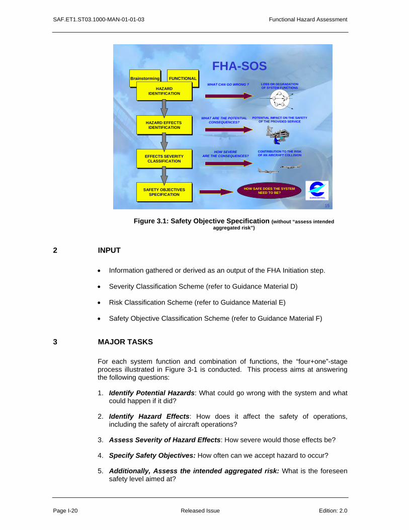
Figure 3.1: Safety Objective Specification (without “assess intended aggregated risk”)
2 INPUT
• Information gathered or derived as an output of the FHA Initiation step.
• Severity Classification Scheme (refer to Guidance Material D)
• Risk Classification Scheme (refer to Guidance Material E)
• Safety Objective Classification Scheme (refer to Guidance Material F)
3 MAJOR TASKS
For each system function and combination of functions, the “four+one”-stage process illustrated in Figure 3-1 is conducted. This process aims at answering the following questions:
1. Identify Potential Hazards: What could go wrong with the system and what could happen if it did?
2. Identify Hazard Effects: How does it affect the safety of operations, including the safety of aircraft operations?
3. Assess Severity of Hazard Effects: How severe would those effects be?
4. Specify Safety Objectives: How often can we accept hazard to occur?
5. Additionally, Assess the intended aggregated risk: What is the foreseen safety level aimed at?
Functional Hazard Assessment SAF.ET1.ST03.1000-MAN-01-01-03
Edition: 2.0 Released Issue Page I-21
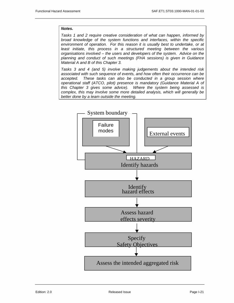
Notes. Tasks 1 and 2 require creative consideration of what can happen, informed by broad knowledge of the system functions and interfaces, within the specific environment of operation. For this reason it is usually best to undertake, or at least initiate, this process in a structured meeting between the various organisations involved – the users and developers of the system. Advice on the planning and conduct of such meetings (FHA sessions) is given in Guidance Material A and B of this Chapter 3.
Tasks 3 and 4 (and 5) involve making judgements about the intended risk associated with such sequence of events, and how often their occurrence can be accepted. These tasks can also be conducted in a group session where operational staff (ATCO, pilot) presence is mandatory (Guidance Material A of this Chapter 3 gives some advice). Where the system being assessed is complex, this may involve some more detailed analysis, which will generally be better done by a team outside the meeting.
Failure modes External events
System boundary
HAZARDIdentify hazards
Identifyhazard effects
Assess hazardeffects severity
SpecifySafety Objectives
Assess the intended aggregated risk
SAF.ET1.ST03.1000-MAN-01-01-03 Functional Hazard Assessment
Page I-22 Released Issue Edition: 2.0
Figure 3-2. Overall FHA-SOS Process
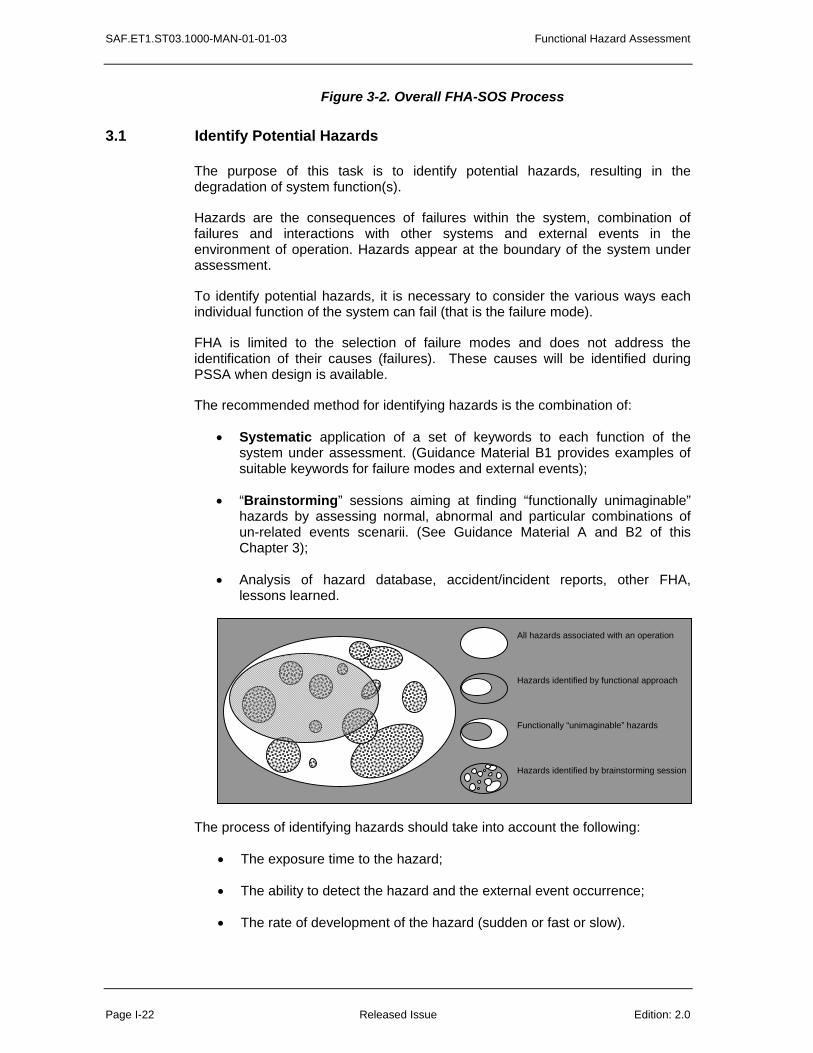
3.1 Identify Potential Hazards
The purpose of this task is to identify potential hazards, resulting in the degradation of system function(s).
Hazards are the consequences of failures within the system, combination of failures and interactions with other systems and external events in the environment of operation. Hazards appear at the boundary of the system under assessment.
To identify potential hazards, it is necessary to consider the various ways each individual function of the system can fail (that is the failure mode).
FHA is limited to the selection of failure modes and does not address the identification of their causes (failures). These causes will be identified during PSSA when design is available.
The recommended method for identifying hazards is the combination of:
• Systematic application of a set of keywords to each function of the system under assessment. (Guidance Material B1 provides examples of suitable keywords for failure modes and external events);
• “Brainstorming” sessions aiming at finding “functionally unimaginable” hazards by assessing normal, abnormal and particular combinations of un-related events scenarii. (See Guidance Material A and B2 of this Chapter 3);
• Analysis of hazard database, accident/incident reports, other FHA, lessons learned.
The process of identifying hazards should take into account the following:
• The exposure time to the hazard;
• The ability to detect the hazard and the external event occurrence;
• The rate of development of the hazard (sudden or fast or slow).
Hazards identified by brainstorming session
All hazards associated with an operation
Functionally “unimaginable” hazards
Hazards identified by functional approach

Functional Hazard Assessment SAF.ET1.ST03.1000-MAN-01-01-03
Edition: 2.0 Released Issue Page I-23
Hazards are identified at the boundary of the system or service under assessment e.g. hazard at:
• Air Navigation System or Service level (e.g. total loss of ATM service for more than 30’);
• Service level (e.g. datalink services: mis-direction of ATC Clearance); • Functional level (e.g. surveillance: corruption of track position); • System level (e.g. Air Traffic Control Centre: loss of adjacent centre
connection); • Sub-system level (e.g. FDP equipment: delay for more than 30’ of Flight
plan update).
(Refer to Guidance Material B1 of this Chapter 3).
An end-to-end (or total system) approach is needed for system safety assessment in order to assess the impact of the system hazards at the overall ANS level (so including the end user: aircraft, aircrew and passengers).
Some ANS/ATM-only hazards could be identified due to local ANS/ATM implementation of the system (e.g. Local ANSP HMI related hazards for Air-Ground data communications).
3.2 Identify Hazard Effects
The purpose of this task is to identify the possible consequences of hazards on operations, including the effects of hazards on aircraft operations.
In order to determine the effects of hazards on operations, various elements should be considered, such as:
• Effects on the ability to provide safe Air Navigation Service;
• Effects on ATCOs working conditions (e.g., workload, ability to perform his/her tasks);
• Effect on Air Crew working conditions (e.g., workload, ability to perform his/her tasks);
• Effects on Aircrew and ATCOs ability to cope with adverse operational and environmental conditions;
• Effect on the functional capabilities of the aircraft;
• Effect on the functional capabilities of the ground part of the Air Navigation System.
When the system under assessment is at a lower level than the Air Navigation Service Provision, it could appear difficult to assess the effect of such lower level hazards directly on aircraft operations. However, the aim is to assess effects also on aircraft operations (aircraft equipment or Flight crew), even if the immediate effects are on ATCOs workload or ability to maintain safe separation and/or on the functional capabilities of the ground part of the Air Navigation System.

SAF.ET1.ST03.1000-MAN-01-01-03 Functional Hazard Assessment
Page I-24 Released Issue Edition: 2.0
In general, identification of the effects of hazards is best performed within the FHA session where operational staff (ATCO, pilot) presence is mandatory (See Guidance Material A).
Guidance Material C provides more detailed suggestions for the factors to take into account in determining the effects of hazards.
3.3 Assess Hazard Effects Severity
The purpose of this task is to classify the severity associated with each hazard effect. The Severity Classification Scheme is used for this purpose (refer to Guidance Material D).
The overall criterion to assess the severity of hazard effects is the effect on operations. It includes the effect on aircraft operations but also, especially in cases where the system to be changed/modified is at the lower level, additional criteria may be used, such as those described in Guidance material C.1 of this Chapter 3.
When assessing the severity of the hazard effects on operations, including aircraft operations, the following sets of indicators should be considered:
• Effects on Air Navigation Service: effects on ANS within the area of responsibility, ATCO and Flight Crew working conditions, ATCO and Air Crew ability to cope with adverse operational and environmental conditions;
• The exposure to the hazard: exposure time, number of aircraft exposed;
• Recovery indicators: annunciation, detection and diagnosis, contingency measures available, rate of development of the hazardous condition;
• The flight phase (effects may vary from flight phase to flight phase);
The rationale for the classification should be given: this could be engineering and/or operational judgement, relevant experience with similar system, etc.
Guidance Material D provides some advice on the practical use of a Severity Classification Scheme within the FHA.
3.4 Specify Safety Objectives
The purpose of this task is to specify system Safety Objectives in order that the system achieves an acceptable level of risk. Safety Objectives are derived from the Organisation Risk Classification Scheme (See Guidance Material E) or Safety Objective Classification Scheme (See Guidance Material F). Guidance Material G illustrates the process of Safety Objectives derivation.
Safety Objectives specify the maximum acceptable frequency for the occurrence of a hazard. Safety Objectives should be specified quantitatively.
In cases where it appears impracticable, qualitative Safety Objectives may be specified substantiated with a rationale explaining why.
Functional Hazard Assessment SAF.ET1.ST03.1000-MAN-01-01-03
Edition: 2.0 Released Issue Page I-25
Safety Objectives may be defined relative to those for some system, which is already accepted as safe enough (usually the current system) with a rationale explaining why Absolute Quantitative Safety Objectives were found impracticable.
Guidelines to choose the most appropriate form for the Safety Objectives and to set quantitative values where achievable are given in Guidance Material G of this Chapter 3.
3.5 Assess the intended aggregated risk (or effect on safety)
At the FHA level, “Intended risk” is used as only a goal for a level of risk or safety level can be specified (FHA is done during the system definition phase). The actual risk will be finally achieved only when operating the system and consequently actual risk will be assessed during SAM 3rd step: SSA (System Safety Assessment).
Note: This step has to be achieved only if Safety Objectives are set without an explicit link to an intended acceptable level of risk (so using Methods 2, 3 or 4 of SAM-FHA Guidance Material G as only Method 1 makes an explicit link to risk).
In order to make text more readable, here after “change” means “change(s) to the existing system or new system”.
The impact of the change could be:
• Positive Impact. There are two scenarii for positive impact on safety.
• Firstly – change mitigates risk for risk not created by the change.
• Secondly – change mitigates risk for risk created by the change itself and achieves a lower risk than before the change.
The list of potential risk reducing effects should be drawn to assess that impact.
• Negative Impact. To create additional risk and/or not to mitigate the risk the change is designed to mitigate.
This negative impact can be acceptable only as long as the final system (including the change) intends to achieve an overall risk that remains acceptable (even though the change does not improve the level of safety).
Changes are usually introduced to improve performance while not impairing and where possible improving the level of safety. To assess the overall safety effect, both positive and negative effects of the change should be considered.
At the end of the FHA, the assessment should finally demonstrate that the system (including the change) intends to achieve an overall acceptable risk. A useful tool to achieve that is “Barrier Analysis” (See Guidance material I of this Chapter 3). It consists in assessing for all the barriers:
• Negative impact:
• Decide on the level of barrier efficiency degradation because of any single hazardous scenario and overall hazardous scenarii identified;

SAF.ET1.ST03.1000-MAN-01-01-03 Functional Hazard Assessment
Page I-26 Released Issue Edition: 2.0
• Decide on the overall effect on the risk due to the overall barriers efficiency degradation;
• Positive impact:
• Decide on the level of barrier efficiency increase because of the change;
• Decide on the overall effect on the risk due to the overall barriers efficiency increase;
• Net result:
• Decide on the combined effects of barrier efficiency degradation and barrier efficiency increase.
4 OUTPUT
The outputs of this step are the lists of:
• Hazards, with the rationale for the severity classification of their effects;
• Safety Objectives;
• Assumptions.
Guidance Material H describes possible means for recording the outputs of FHA sessions.
The output of the Safety Objectives Specification step should be formally placed under configuration management. List of Guidance Material of FHA Chapter 3:
A. Planning and conducting FHA session; B. Identification of failure modes, external events and hazards; C. Identification of Hazard effects; D. Severity Classification Scheme; E. Risk Classification Scheme; F. Safety Objective Classification Scheme; G. Methods for setting Safety Objectives; H. Results records; I. Barrier Analysis; J. TLS (Target Level of Safety) apportionment method.
Other Guidance Material applying to this Chapter 3 (FHA - Safety Objectives Specification):
• SAM – Part IV Annex A: Acronym; • SAM – Part IV Annex B: Glossary; • SAM – Part IV Annex D: Safety Techniques Survey (report and
technical annex).
Functional Hazard Assessment SAF.ET1.ST03.1000-MAN-01-01-04
Edition: 2.0 Released Issue Page I-27
4
FHA EVALUATION
1 OBJECTIVES
The objective of the FHA Evaluation step is to demonstrate that the FHA process meets its overall objectives and requirements. This is carried out in three stages:
• Verification;
• Validation;
• Process Assurance.
Note: The division into three major tasks (Verification, Validation and Process Assurance) is intended to help the Methodology’s users ensuring correctness and completeness of the process.
It is recognised that there are areas of overlap between the activities suggested under each, and that the precise method of implementation will depend on the system considered and the user’s current practices.
The guidance is not intended to specify the only way of meeting the FHA objectives.
Their relationships with the overall process are shown in Figure 4-1.

SAF.ET1.ST03.1000-MAN-01-01-04 Functional Hazard Assessment
Page I-28 Released Issue Edition: 2.0
FHA
VERIFICATION FHA COMPLETION
SAFETY OBJECTIVESSPECIFICATION
FHA VALIDATION
FHA
PROCESS
ASSURANCE
FHA INITIATION
FHA PLANNING
Figure 4-1 - Relationships between FHA Evaluation Activities and the Overall FHA Process
The objective of FHA Verification is to demonstrate that the set of Safety Objectives meet the Organisation Safety Target, i.e. the overall acceptable level of risk (“getting the output right”).

Functional Hazard Assessment SAF.ET1.ST03.1000-MAN-01-01-04
Edition: 2.0 Released Issue Page I-29
The objective of FHA Validation is to ensure that the outputs of the FHA process are correct and complete (“getting the right output”), i.e. that:
• The Safety Objectives are (and remain) correct and complete;
• All safety-related assumptions are credible, appropriately justified and documented.
The objectives of FHA Process Assurance (“getting the process right and the right process”) are:
• To provide assurance and evidence that all FHA activities (including FHA Verification and FHA Validation) have been conducted according to the FHA plan;
• To ensure that the FHA process as described in the FHA Plan is correct and complete.
2 INPUT
• Information gathered or derived during the FHA steps.
• Initial Safety Plan and FHA Plan.
• Intermediate and final outputs of the FHA process.
3 MAJOR TASKS
Notes.
Relationships with overall System Verification and Validation activities. The activities described in this chapter are limited to the verification of FHA outputs and to the validation of Safety Objectives (and related assumptions). These specific activities could be combined with or integrated into the overall system Definition Verification and Validation processes. It is essential to consider, in the overall Verification and Validation processes, other system specification errors (for example, operational, interoperability, security, engineering or environmental specifications),which could subsequently impact safety.
Relationships with Quality Management activities. As the tasks of Verification, Validation and Process Assurance are similar in intent with Quality Management activities, they could be combined with or integrated into the Quality Management process.
Independence. To ensure an independent view, all of these activities should, where possible, be conducted by one or more persons not involved in the performance of the assessment itself.
For large and complex Projects/Programmes, these tasks could be performed by an independent department or organisation.

SAF.ET1.ST03.1000-MAN-01-01-04 Functional Hazard Assessment
Page I-30 Released Issue Edition: 2.0
While there are benefits in independent checks, the findings should be fed back to those who were involved in the original work. The participants in the FHA session, for example, should have the opportunity to comment on whether their input has been correctly understood. They may also need to review their assumptions once the collated results are available, giving a clearer view of the implications than during the FHA session.
Such feedback will have the added benefit of contributing to future motivation to take part in such exercises (some useful output being seen to have emerged) and to ‘organisational learning’ – the breadth and depth of knowledge within the organisation.
3.1 FHA Verification Tasks
• Review and analyse the results of the FHA process.
Note: Verification is ongoing throughout the FHA. It also applies to FHA Validation.
Note: See Guidance Material A of this Chapter 4.
3.2 FHA Validation Tasks
• Review and analyse the Safety Objectives to ensure their completeness and correctness;
• Review and analyse the description of the operational environment to ensure its completeness and correctness;
• Review, analyse, justify and document safety-related assumptions about the system, its operational environment and its regulatory framework to ensure their completeness and correctness.
• Review and analyse traceability between functions, hazards, hazard’s effects and Safety Objectives.
• Review and analyse the credibility and sensitivity of Safety Objectives with respect to assumptions and risk.
Note: See Guidance Material B of this Chapter 4.
Functional Hazard Assessment SAF.ET1.ST03.1000-MAN-01-01-04
Edition: 2.0 Released Issue Page I-31
3.3 FHA Process Assurance
The FHA Process assurance task should at least ensure in accordance with the FHA Plan that:
• The FHA steps are applied;
• Assessment approaches (e.g. use of safety methods and techniques) are applied;
• All outputs of the FHA steps, including FHA Verification, FHA Validation and FHA Process Assurance are formally placed under configuration management;
• Any deficiencies detected during FHA Verification or FHA Validation activities have been resolved;
• The FHA process would be repeatable by personnel other than the original analyst(s);
• The findings have been disseminated to interested parties;
• Outputs of the FHA process are not incorrect and/or incomplete due to deficiencies in the FHA process itself.
Note: When changes are made to the specification, design, implementation or use of a system, process assurance should also ensure that the impacts of these changes on the current FHA results have been considered and that all required assessment, verification and validation activities have been performed.
Note: See Guidance Material C of this Chapter 4.
4 OUTPUT
The output of the FHA Evaluation is the assurance and evidence collected during the FHA Verification, FHA Validation and FHA Process Assurance tasks.
The FHA output comprises:
• Results of the FHA Verification task: including the information collected during the various reviews of FHA output, for assurance and evidence that Safety Objectives meet Organisation Safety Target;
• Results of the FHA Validation task: including the arguments for assurance and evidence of the completeness and correctness of Safety Objectives and assumptions;

SAF.ET1.ST03.1000-MAN-01-01-04 Functional Hazard Assessment
Page I-32 Released Issue Edition: 2.0
• Results of the FHA Process Assurance task: including the information collected during the various activities for assurance and evidence that the FHA process as described in the FHA Plan has been conducted and that FHA process is correct and complete.

Functional Hazard Assessment SAF.ET1.ST03.1000-MAN-01-01-05
Edition : 2.0 Released Issue Page I-33
5
FHA COMPLETION
1 OBJECTIVE
The objectives of the FHA Completion step are:
• To record the results of the complete FHA process;
• To disseminate these results to all interested parties.
2 INPUT
• Outputs from all other FHA steps.
3 MAJOR TASKS
• Document the results of the FHA process (including the results of Safety Objectives Specification, FHA Verification, FHA Validation and FHA Process Assurance activities).
• Formally place the FHA documentation under configuration management.
• Disseminate the FHA documentation to all interested parties.

SAF.ET1.ST03.1000-MAN-01-01-05 Functional Hazard Assessment
Page I-34 Released Issue Edition : 2.0
4 OUTPUT
• FHA results, under configuration management.
Guidance Material A of this Chapter 5 suggests possible format for documenting the FHA results.

FHA - OED SAF.ET1.ST03.1000-MAN-01-01-01-A
Edition: 2.0 Released Issue Page A - 1
A
CHAPTER 1 GUIDANCE MATERIAL:
OPERATIONAL ENVIRONMENT DEFINITION
Functional Hazard Assessment can only be properly conducted when considering the Air Navigation system being assessed within the context of the operational environment in which it will be integrated.
The description of the operational environment should include all characteristics which may be relevant when assessing the safety impact of the loss or degradation of the new/modified system’s functions. In cases where elements of the environment of operation may be used as compensating factors in the assessment of the severity of the identified hazard effects, the best practise is

SAF.ET1.ST03.1000-MAN-01-01-01-A FHA - OED
Page A - 2 Released Issue Edition: 2.0
that they should be identified and agreed with the regulatory authorities before initiating the safety assessment process.
The definition of the operational environment requires a description of the current operations and ATM/CNS capabilities that support these operations. It also requires a description of the environmental characteristics, i.e. those outside the ATM/CNS domain.
Operationaljustification
SystemDescription Description of
the operationalenvironment
Description ofthe legislativeenvironment
Description ofthe boundariesand interfaces
Functionaldescription Operational
description
HumanResources
equipment
Proceduresand Human
Factors
SW
HW
Adaptationdata
present
transitionintended
logical
physical
Contextof the
Assessment
Aircrafttrajectoriesdescription
tasks
Pilots
ATCo
Otherparties
geographical
time
spatial
Figure A-1: Context of the assessment
The following are some examples of characteristics that need to be described:
• Current ATM/CNS capabilities: functionality, performance and limitations, level of automation e.g., description of current equipment, navigation capability and performance (RNP, RNAV), surveillance capability and performance (PSR, SSR, ADS), communication capability and performance (voice and data-link), proficiency of ATCOs, current procedures (operational, maintenance, etc.), availability of safety nets;
• Airspace Characteristics: airspace classification, separation minima, route configuration and complexity, sectorisation, special use airspace restrictions;

FHA - OED SAF.ET1.ST03.1000-MAN-01-01-01-A
Edition: 2.0 Released Issue Page A - 3
• Traffic Characteristics: traffic complexity, (current or foreseen) sector traffic density, (current or foreseen) track occupancy; Military operations, General Aviation operations;
• Aircraft Performance and Equipment: aircraft performance requirements, traffic is generally a mix of aircraft with different performances and levels of equipment fit.
• Adjacent Centre Capabilities: characteristics of ATC Unit with which traffic is exchanged (performances and limitations);
• Airport Infrastructure: e.g. the characteristics of airport movement area (runways, taxiways), availability of visual aids;
• Weather: local weather phenomena (e.g., turbulence over mountainous terrain, fog patterns, intensity of thunderstorms, volcanic ash);
• Topography: e.g., significant obstacles at and around airport, terrain characteristics;
• Environmental Constraints: e.g., noise sensitivity of populated areas in the environment of an airport.
This list is not exhaustive. Moreover some characteristics, such as Weather, Topography and Environment Constraints, may not be relevant for all types of system. However, in some cases, this information could be required in further steps of the safety assessment process.
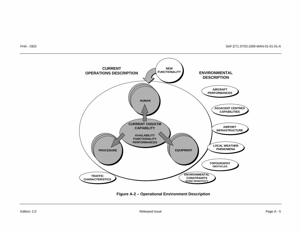
Figure A-2 summarises these characteristics and how they relate to each other and to the system being assessed.
Additional Guidance Material
• ICAO Manual on Airspace Planning Methodology for the Determination of Separation Minima Doc 9689-AN/953 (First Edition - 1998)
• EUROCAE ED78A, Annex C, OSED Guidance Guidelines for Approval of the Provision and Use of Air Traffic Services Supported by Data Communications, (December 2000)
• B. Ruitenberg, Situational Awareness in ATC – A Model The Controller (March 1997)

FHA - OED SAF.ET1.ST03.1000-MAN-01-01-01-A
Edition: 2.0 Released Issue Page A - 5
ENVIRONMENTALDESCRIPTION
LOCAL WEATHERPHENOMENA
AIRPORTINFRASTRUCTURE
CURRENTOPERATIONS DESCRIPTION
ENVIRONMENTALCONSTRAINTS
NOISE SENSITIVITY
AIRCRAFTPERFORMANCES
CURRENT CNS/ATMCAPABILITY
AVAILABILITYFUNCTIONALITYPERFORMANCES
ADJACENT CENTRESCAPABILITIES
TRAFFICCHARACTERISTICS
HUMAN
PROCEDURE EQUIPMENT
NEWFUNCTIONALITY
TOPOGRAPHYOBSTACLES
Figure A-2 – Operational Environment Description

SAF.ET1.ST03.1000-MAN-01-01-01-A FHA – OED
Page A-6 Released Issue Edition: 2.0
This page is intentionally left blank.

FHA – Planning SAF.ET1.ST03.1000-MAN-01-01-02-A
Edition: 2.0 Released Issue Page A-1
A
CHAPTER 2 GUIDANCE MATERIAL:
PLANNING FHA ACTIVITIES
1 INTRODUCTION
This guidance material outlines the tasks involved in defining the approach to safety within the FHA itself.

SAF.ET1.ST03.1000-MAN-01-01-02-A FHA – Planning
Page A-2 Released Issue Edition: 2.0
2 FHA OBJECTIVES AND SCOPE
• Define the objectives of the Functional Hazard Assessment; and how these will contribute to overall safety assessment for the system.
• As part of the total system approach, co-ordination between stakeholders:
• ANSPs: engineers, ATCOs, ..; • Regulators: ATM, airworthiness, flight operations; • Users: airlines, pilots, ..; • Industry: equipment manufacturers (aircraft, “ground”),
Communication Service Providers, … • Others as necessary.
should be performed to develop and validate operational concept which will be used as input of the safety assessment. This includes co-ordination for Safety Objectives specification.
• Define the scope and level of the FHA. For example:
The scope of the FHA depends on the scope of the system under assessment. Total system approach can be limited to ground ATM, as long as it can be demonstrated that the system being assessed (the scope of FHA) is not directly interacting with the airborne segment.
FHA can be applied at different levels, from overall ATM Service Provision level to sub-system level.
Different levels of FHA could be conducted, dependent on whether certain functions have already been allocated to particular system elements;
A specific FHA could be conducted to cover the transition between the current and future operations or the decommissioning of the system;
For new concepts where refinement of the mode of operation, operational environment, .. will be achieved through iterations, it is useful to consider a phased approach to the FHA going along with a progressive development of the Concept of Operations since FHA has to be commensurate with lifecycle and the level of design detail. Phased approach enables the safety assessment process to influence the definition of procedures and human-related issues.
3 FHA PROCESS
• Identify the inputs to the FHA process (drawing on the material gathered under the FHA Initiation step, as described in Chapter 1);
FHA – Planning SAF.ET1.ST03.1000-MAN-01-01-02-A
Edition: 2.0 Released Issue Page A-3
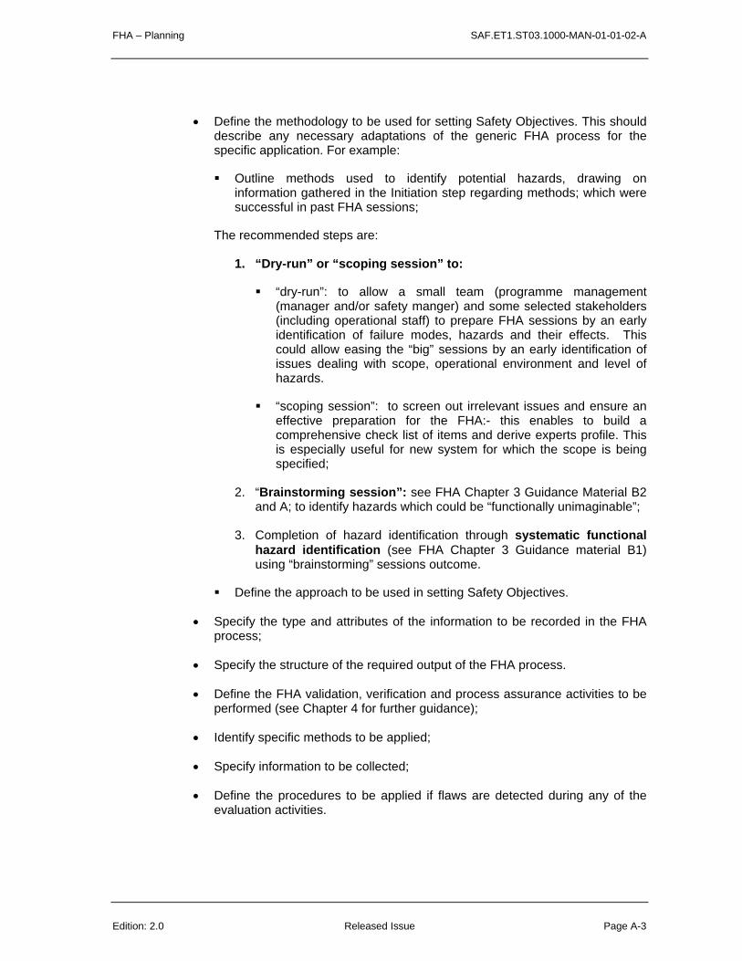
• Define the methodology to be used for setting Safety Objectives. This should describe any necessary adaptations of the generic FHA process for the specific application. For example:
Outline methods used to identify potential hazards, drawing on information gathered in the Initiation step regarding methods; which were successful in past FHA sessions;
The recommended steps are:
1. “Dry-run” or “scoping session” to:
“dry-run”: to allow a small team (programme management (manager and/or safety manger) and some selected stakeholders (including operational staff) to prepare FHA sessions by an early identification of failure modes, hazards and their effects. This could allow easing the “big” sessions by an early identification of issues dealing with scope, operational environment and level of hazards.
“scoping session”: to screen out irrelevant issues and ensure an effective preparation for the FHA:- this enables to build a comprehensive check list of items and derive experts profile. This is especially useful for new system for which the scope is being specified;
2. “Brainstorming session”: see FHA Chapter 3 Guidance Material B2 and A; to identify hazards which could be “functionally unimaginable”;
3. Completion of hazard identification through systematic functional hazard identification (see FHA Chapter 3 Guidance material B1) using “brainstorming” sessions outcome.
Define the approach to be used in setting Safety Objectives.
• Specify the type and attributes of the information to be recorded in the FHA process;
• Specify the structure of the required output of the FHA process.
• Define the FHA validation, verification and process assurance activities to be performed (see Chapter 4 for further guidance);
• Identify specific methods to be applied;
• Specify information to be collected;
• Define the procedures to be applied if flaws are detected during any of the evaluation activities.

SAF.ET1.ST03.1000-MAN-01-01-02-A FHA – Planning
Page A-4 Released Issue Edition: 2.0
4 ROLES AND RESPONSIBILITIES
• Define the roles and responsibilities of the persons, departments and organisations involved in the FHA process in particular in order to ensure that adequate coordination is performed for Safety Objectives specification such as:
• regulatory bodies for ATM, airworthiness and flight operations;
• ANSPs (including ATCOs);
• Airlines (including aircrew);
• Aircraft and aircraft equipment manufacturers;
• ANSP equipment manufacturers;
• Any other required bodies (such as Communication Service Providers, …).
• Specify the required competencies for the persons involved in the FHA process, and any necessary training requirements.
5 SCHEDULE AND RESOURCE ALLOCATION
• Define the time schedule and resources required.
6 PLANNING FOR FUTURE ACTIVITIES
• Define the procedures to be applied when changes are made to Safety Objectives, system functions, operational environment or system interfaces. Defining adequate lines of communication is particularly important – safety assessors need to be informed of such changes.


SAF.ET1.ST03.1000-MAN-01-02-A FHA – Planning
Page A-6 Released Issue Edition: 2.0

SAF.ET1.ST03.1000-MAN-01-01-03-A FHA Session
Page A-2 Released Issue Edition: 2.0
A
CHAPTER 3 GUIDANCE MATERIAL:
PLANNING AND CONDUCTING FHA SESSIONS
1 PURPOSE
The purpose of this Guidance Material is to provide recommendations to conduct sessions to identify hazard and its worst credible effect, so when using methods 2 & 4 of setting Safety Objectives (See FHA Chapter 3 Guidance Material G).

FHA Session SAF.ET1.ST03.1000-MAN-01-01-03-A
Edition: 2.0 Released Issue Page A-3
2 THE ROLE OF THE FHA GROUP
It is usually best to initiate the FHA process in a group session, involving representatives of the various organisations concerned with the specification, development and use of the system.
The interactions between participants with varying experience and knowledge tend to lead to broader, more comprehensive and more balanced consideration of safety issues than if FHA was conducted by an individual as a desk study.
While group sessions are usually good at generating ideas, identifying issues and making an initial assessment, they do not always produce these outputs in a logical order. Also, it is difficult for a group to analyse the ideas and issues in detail – it is hard to consider all the implications and inter-relationships between issues when these have only just been raised. Much time can be wasted in highly technical discussions which may turn out to be irrelevant.
It is therefore recommended that:
• The group session should be used to generate ideas and undertake preliminary assessment only (perhaps identifying factors that are important, rather than working through the implications in detail).
• The findings should be collated and analysed after the session. This should be done by one or two individuals with sufficient breadth of expertise to understand all the issues raised, and a good appreciation of the purposes of the FHA. The person who facilitated or recorded the session will often be best able to perform this task.
• The collated results should be fed back to the group, to check that the analysis has correctly interpreted their input, and to provide an opportunity to reconsider any aspects once the ‘whole picture’ can be seen.
3 FHA SESSION PARTICIPANTS
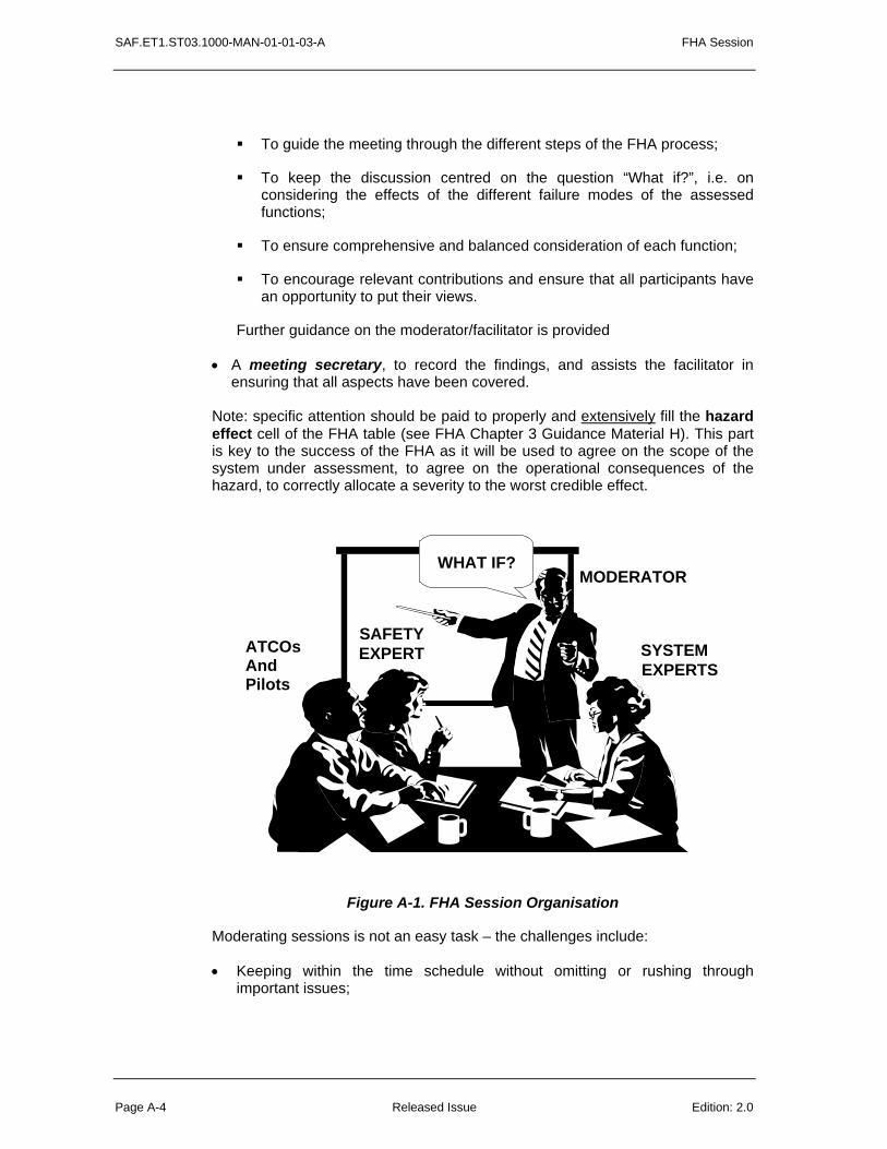
As illustrated in Figure A-1, Functional Hazard Assessment sessions need to involve representatives of all the main stakeholders in the system and its safety. Typically, a session should involve:
• System users: ATCOs and Flight Crew (where necessary), to assess the consequences of hazard(s) from an operational perspective;
• System technical experts, to explain the system purpose, interfaces and functions;
• Safety and human factors experts, to guide in the application of the FHA methodology itself and to bring wider experience of the effects of hazards;
• A ‘moderator’ or ‘facilitator’ to lead the session. His/her main tasks will be:
SAF.ET1.ST03.1000-MAN-01-01-03-A FHA Session
Page A-4 Released Issue Edition: 2.0
To guide the meeting through the different steps of the FHA process;
To keep the discussion centred on the question “What if?”, i.e. on considering the effects of the different failure modes of the assessed functions;
To ensure comprehensive and balanced consideration of each function;
To encourage relevant contributions and ensure that all participants have an opportunity to put their views.
Further guidance on the moderator/facilitator is provided
• A meeting secretary, to record the findings, and assists the facilitator in ensuring that all aspects have been covered.
Note: specific attention should be paid to properly and extensively fill the hazard effect cell of the FHA table (see FHA Chapter 3 Guidance Material H). This part is key to the success of the FHA as it will be used to agree on the scope of the system under assessment, to agree on the operational consequences of the hazard, to correctly allocate a severity to the worst credible effect.
WHAT IF?MODERATOR
ATCOsAndPilots
SYSTEMEXPERTS
SAFETYEXPERT
Figure A-1. FHA Session Organisation
Moderating sessions is not an easy task – the challenges include:
• Keeping within the time schedule without omitting or rushing through important issues;

FHA Session SAF.ET1.ST03.1000-MAN-01-01-03-A
Edition: 2.0 Released Issue Page A-5
• Maintaining a structured approach, and keeping the discussion relevant, without suppressing new and unexpected ideas;
• Allowing all participants an equal opportunity to contribute.
Ideally an well-experienced and trained moderator should be used.
4 SESSION PSYCHOLOGY
Some consideration of the individual and group psychology involved an FHA session is helpful in understanding how to run a successful session.
The mental processes required from each participant in order to produce the desired outputs can be categorised under two broad kinds of thinking:
• Creative (inductive) thinking: This is important in the identification of failure mode(s), external events, sequence of events, hazards and the hazard effects that may result. The basic type of question being asked is ‘What could go wrong?’. Section A.3.1 provides additional guidance for this process.
• Judgmental (deductive) thinking. This is important in classifying the severity of hazard effects and in setting the Safety Objectives. The basic questions are ‘How severe are the effects of this sequence of events’. Section A.3.2 provides additional guidance for this process.
The above are cognitive processes, undertaken by each individual participant, but the group dynamics of the session are also important in determining its success. (see section A.3.3)
3.1 The Creative Process - Identifying What Could Go Wrong
Creative thinking is necessary to ensure that the identification of potential failure mode(s), and the potential resulting hazards is as comprehensive as possible. It is important to encourage participants to think widely and imaginatively around the subject, initially without analysis or criticism.
Typically, this is achieved by a process of structured brainstorming. The structure should both ensure completeness and encourage (not constrain) wide-ranging thinking about the system.
In a FHA session, the highest level of structure is dictated by the need for systematic consideration of each function of the system. To ensure completeness, it is often useful for the facilitator to lead the session through other, or more detailed, ways of considering the system. Examples of such lower-level structuring include:

SAF.ET1.ST03.1000-MAN-01-01-03-A FHA Session
Page A-6 Released Issue Edition: 2.0
• Consideration of other ‘dimensions’ of the problem, such as flight phases or operational scenarios. This helps to prevent participants becoming too ‘locked in’ to a mental model based purely on system functions.
• Prompt words, expressing what can go wrong, can be applied to each function of the system. Guidance Material B suggests prompt words for the identification of failure modes and external events. Wherever the combination of function and prompt word leads to the identification of a credible failure mode, the session should go on to discuss what hazards may arise from that failure mode.
• Participants should be encouraged to think beyond their own experience, considering how others might use the system and the errors they might make. To help with this, and to overcome any inhibitions participants may have about mentioning errors which they themselves have made, it can be helpful to ask what errors others – such as an inexperienced or fatigued controller or a pilot under stress – might make.
• Participants can be prompted to recall relevant incidents they have experienced or heard about. It may be helpful for the facilitator to outline a few examples and ask for others.
• Participants should be encouraged to consider latent and organisational failure modes as well as the more obvious (active) failure modes manifested during operation. Some prompt words are suggested in Guidance Material B.
• Participants should also be encouraged to compare potential resulting effects considering the possibility to detect or not a hazard occurrence.
• Where a comparative approach is being taken (‘Is the system as safe as what currently exists?’) it is useful to begin the session by brainstorming what are the key differences between the existing and proposed systems. This can also be helpful where a FHA has already been performed for a similar system, especially by the same group, or when considering a number of variants, as it helps avoid repetition.
A recurrent problem in designing FHA sessions is how to cover all the possible combinations of failure modes, prompt words and other ways of breaking down the problem in the time available. Rather than working through all combinations exhaustively, it may be adequate to talk through the detailed breakdown or prompt list in the introduction, but only work through a broader grouping in the session itself.
Judgements about how detailed a list of potential failure modes should be used, and hence how much time should be devoted to the FHA session, should take into account the status of the system development (how much detail is required) and its potential to cause significant risk.
More detailed prompts can always be introduced at later iterations of the FHA process as the design develops; the main danger to be avoided is that of overlooking significant failure modes at an early stage.
FHA Session SAF.ET1.ST03.1000-MAN-01-01-03-A
Edition: 2.0 Released Issue Page A-7
The FHA session organiser should conduct a ‘dry run’ of the process before the session. By working through a few combinations of functions and keywords, either as a mental exercise or with one or two colleagues, the organiser should be able to check the applicability of the keywords and gauge how much information or discussion each combination is likely to generate.
In such cases users may group the failure modes into a smaller number of prompts, taking care to ensure that the reduced list spans all the possibilities in the full list.
Reminders of the full list can be provided on posters around the room, or on handouts. The facilitator can draw specific attention to such lists if the flow of ideas seems to be exhausted prematurely.
3.2 Judgmental Thinking – Classifying Hazard Effects and Setting Safety Objectives
The aim of this part of the FHA session is to elicit subjective judgements, in such a way as to make the best use of people’s knowledge and experience, and to minimise – or at least reveal - any biases or uncertainties.
Where the functions and hazards are complex and closely inter-linked, session designers should consider running the judgmental part of the session some time after the creative part, to give time to collate the results into a concise form. If this is not possible, the session leaders should make sure they have an opportunity (during a break, for example) to do some preliminary collation of the findings.
Where the functions and hazards can be simply expressed and are clearly distinct, it is generally better to make the severity classification judgements for each hazard effect at the same time as it is identified, since the participants will have the hazard and associated effect in mind.
The group may initially find it difficult to agree on any severity level. It is often easier to agree on the possible range of values that could be taken, or those that are clearly not correct. For example, all members of the group may agree that the hazard effect cannot possibly be above the severity level 2. This range can then be narrowed down to a single consensus value.
Where a consensus cannot be reached, this should be documented. However, lack of consensus often indicates that the hazard or its effects has not been clearly defined, such that participants have differing ideas of what it entails. It may be possible to resolve this in the meeting by defining the hazard and its effects more carefully, or by defining more than one hazard to represent each of the different interpretations.
Once hazard effect was being allocating the severity, the group will have to agree on the probability that each hazard may generate each of its effects. This will help identifying the worst credible case (worst credible effect of the hazard) and so identifying the safety objective of the hazard.
SAF.ET1.ST03.1000-MAN-01-01-03-A FHA Session
Page A-8 Released Issue Edition: 2.0
The hazard effects classification judgements should be tested for consistency with those for other hazard effects. The relative order of severity implied by the classifications should also be looked at, as an indication of the overall balance and correctness of judgements.
In general, FHA sessions do not need to elicit quantitative information in any detail, but there is a large body of literature on techniques if required.
3.3 Group Dynamics
These aspects apply to both the creative and the judgmental aspects of the session.
• Understanding of the process and motivation for attendance. It is important that participants have a common purpose. A pre-meeting briefing should be circulated explaining the purpose and importance of the session, and this should be underlined in the introduction on the day. Facilitators should be aware that, despite such briefings, individuals may still have other motivations for attendance.
• Group size. The size of group is principally determined by the areas of expertise required. However, groups of more than ten or so can be very difficult to control; they tend to break up into sub-groups, and there may be insufficient time for each individual to cover their points in adequate depth. A group of less than three (in addition to the facilitator and secretary) is unlikely to have sufficient breadth of expertise and experience.
• Dominance and reticence. Some individuals may dominate the conversation, others may be reticent, especially about dissenting from a perceived consensus view. Personality, and the hierarchical relationships between individuals, should be taken into account in selecting participants – the aim should be to have a reasonably equally-matched set of individuals.
• Defensiveness. Participants closely involved with the development of a system or its current equivalent may find it hard to admit that things could go wrong. It should be stressed that the identification of a potential hazard should not be seen as a criticism of any work already carried out or of current practice.
• Giving positive feedback during the session is important. All contributions should be seen to be valuable. It is helpful to write down key points visibly (on a flipchart, for example) such that participants know their points are being recorded. This can also be used as a way of pointing out that an issue has already been covered. Irrelevant issues should be passed over quickly, but not criticised destructively.
• Confidentiality. Where representatives of different organisations are present, the facilitator should be aware of possible issues which may affect what participants feel able to say.

FHA Session SAF.ET1.ST03.1000-MAN-01-01-03-A
Edition: 2.0 Released Issue Page A-9
4 GENERAL PRACTICALITIES
The importance of the practical arrangements for the session should not be underestimated. Factors to consider include:
• Location and timing of the session to minimise inconvenience and travel cost.
• Space, comfort, visibility and audibility in the meeting room.
• Providing adequate breaks and refreshments. The attention span and fatigue of the facilitator and secretary should be considered, as well as that of the participants.
• Making allowance for participants being unavailable at the last minute. It is in the nature of FHA sessions that many participants will have operational responsibilities which may have to take precedence. As it can be extremely difficult to find another time when all can be present; potential substitute attendees should be kept in reserve.
• Provision of visual and other aids. An overhead projector, flipchart and whiteboard should be available. Electronic boards and computer projectors can be used to very good effect, enabling participants to see exactly what is being recorded and confirm that the points they make are correctly understood.
• Variety is important in maintaining attention and motivation. Where a session is longer than half a day, designers should consider using varying the structure of the session, for example by using a different ‘dimension’ as in Section A.3.1. in order to introduce variety, as well as for reasons of comprehensiveness.
• Varying the presentation of the session and its findings can also be helpful. For example, the facilitator and secretary could alternate roles for each session – this also helps maintain the facilitator’s enthusiasm for the task. One session could be conducted using overhead slides and a flipchart, another using the computer projector. Participants should be encouraged to make use of the various aids, for example by inviting them to draw on the flipchart to explain a point.

SAF.ET1.ST03.1000-MAN-01-01-03-A FHA Session
Page A-10 Released Issue Edition: 2.0
APPENDIX 1: FACILITATION
See Power Point file: FHA V1-2 Chapter 3 Guidance A.ppt

SAF.ET1.ST03.1000-MAN-01-01-03-B1 FHA – Hazards Identification
Page B1-2 Released Issue Edition: 2.0
B1
CHAPTER 3 GUIDANCE MATERIAL:
IDENTIFICATION OF FAILURE MODES, EXTERNAL EVENTS AND
HAZARDS

FHA – Hazards Identification SAF.ET1.ST03.1000-MAN-01-01-03-B1
Edition: 2.0 Released Issue Page B1-3
1 IDENTIFICATION OF HAZARDS
Hazards can be identified by:
• systematically applying a list of key words, expressing the various failure modes, to each function of the system (See §2 of Guidance Material B1) ;
• systematically applying a list of external events to each function of the system (See §3 of Guidance Material B1);
• Using some abnormal occurrence/event scenario during brainstorming session to identify any additional “functionally unimaginable” hazards (See Guidance Material B2).
Guidance to plan hazard identification activities is described in Guidance Material A of SAM-FHA Chapter 2 and in Guidance Material B2 of this Chapter.
Hazards should be uniquely identified (ex: H-ACL-X) and should be traceable to abnormal events (when relevant).
unimaginable unimaginable
Functionally-imaginable &Functionally-unimaginable & unimaginable hazards
All All
Func-imaginableFunc-unimaginable
Unimaginable hazardsUnimaginable hazards

SAF.ET1.ST03.1000-MAN-01-01-03-B1 FHA – Hazards Identification
Page B1-4 Released Issue Edition: 2.0
Hazards should be labelled as described hereunder:
• [failure mode] of [(sub)-function] for more than [exposure time] in [Operational Environment]; or
• a “short story” including the hazard source (failure mode, external event, abnormal event scenario, combination of failure modes and/or events, …), the hazard mechanism (how it affects Air Navigation Service Provision including aircraft operations).
2 IDENTIFICATION OF FAILURE MODES
Some general categories of failure modes are listed in Table B1-1.
“Failure mode” is a prompt word to be used to identify hazards such as:
Total loss Failure to start
Partial loss Failure to stop
Error of input/ output: Failure to switch
- missing data (partial loss, total loss) Delayed operation (too late)
- detected erroneous/corrupted data (not credible error/corruption)
Premature operation (too early)
- undetected erroneous/corrupted data (credible error/corruption)
Inadvertent operation
- spontaneous data Intermittent or erratic operation
- out of sequence Modified operation
- out of range Violation of operation (Routine or unintentional)
Misdirection of data Misheard
Inconsistent information Misunderstood
Erroneous updating Used beyond intent
Out of time synchronisation
Table B1-1. Examples of Failure Modes
FHA – Hazards Identification SAF.ET1.ST03.1000-MAN-01-01-03-B1
Edition: 2.0 Released Issue Page B1-5
Note: these failure modes are not specific to an architectural element only (technical or at ATCO or procedure level). For example corruption could be caused by lapses, slips of ATCOs or software corruption, mis-direction can be due to ATCO selecting the wrong call-sign or software corruption. However at FHA level, as the architecture is not yet known, this level of detail (cause of the hazard) is not addressed at this stage.
Virtually every type of failure mode can be classified into one or more of these categories, but the list is not necessarily exhaustive. The user should consider whether additional modes apply to the system being considered.
In addition, these generic definitions will sometimes be too broad for definitive analysis. Consequently, they will need to be refined and instantiated for the specific domain of application (e.g., communication, surveillance, etc.)
It will be also necessary to distinguish "detected" and "undetected" failure modes.
The list of failure modes covers both active and latent failures.
Active failures results from operational errors.
Latent failures results from errors or omissions during development (specification, design, implementation, integration and transfer to operations) and maintenance phase of the system life cycle.
For example,
• MISUNDERSTOOD has both an ‘active’ interpretation (e.g., ‘how might a controller misunderstand this alert?’) and a latent one (‘how might future users misinterpret the purpose of this procedure?’).
• USED BEYOND INTENT should prompt ideas about how a future operator might try to use (or misuse) the system in a way not considered by the designers.
• MODIFIED should prompt consideration of how future users might try to modify the system, without appreciating the design rationale.
Latent failures require particular attention and emphasis in FHA sessions, as it is generally much easier to think of active failures.
How to use?
Ideally, a detailed list of failure mode prompts, such as that in Table B-1 should be selected (meaningful to the system under assessment) and systematically applied to each function.

SAF.ET1.ST03.1000-MAN-01-01-03-B1 FHA – Hazards Identification
Page B1-6 Released Issue Edition: 2.0
But it is recognised that this may not be practical, given the number of functions to be considered and the time available.
Where reduced lists of prompts are derived, it is helpful to draw the attention of FHA session participants to the full list, at least in the introduction to the session and possibly by providing handouts or other reminders for use during the session (see Guidance A).
3 IDENTIFICATION OF EXTERNAL EVENTS
A list of external events should be systematically applied to system functions in order to identify all hazards, since some of them may result from the interactions between the system and the environment of operation.
Examples of such external events, which should be taken into consideration in the process of identifying the hazards, are listed in the FHA - Chapter 1, Guidance Material A figure A-2.

FHA – Hazards Identification SAF.ET1.ST03.1000-MAN-01-01-03-B1
Edition: 2.0 Released Issue Page B1-7
4. HAZARD VERSUS SCOPE OF THE SYSTEM UNDER ASSESSMENT
When identifying hazards, different levels of hazards could be considered as a hazard is at the boundary of the scope of the system under assessment. Ideally hazards should be at the level of the Air Navigation System or Service. However if the scope of the system under assessment is reduced to a sub-level of this Air Navigation System or Service, the hazards will be identified at the boundary of that sub-system.
The Figure bellow illustrates that if the scope of the system under assessment is At level A (sub-sub-system), then what is considered as a hazard :
Flight Planning
procedures
not updated
Flight Plan
not filed
correctly
Incorrect display
of RVSM Status Information
Incorrect exchange
of RVSM Status Information
Incorrectseparation minima
applied
ATM Level:E
ATM Component Level:D
System Level: C
Sub-System Level: B
Sub-Sub-System Level:A
Figure B-1: Hazard at the boundary of the system under assessment
If the system under assessment is at lower level, such as sub-sub-system level A, for example if training programme for pilots should be changed due to introduction of RVSM, a hazard that could appear at the boundary of system “A” is “Flight Planning procedures not updated”.
But if the system under assessment is the FDPS (level C), one of the hazards identified could be “incorrect display of RVSM Status information”.

SAF.ET1.ST03.1000-MAN-01-01-03-B1 FHA – Hazards Identification
Page B1-8 Released Issue Edition: 2.0
At the ATM Component level “D”, if the inter-centre co-ordination process is assessed, a hazard appearing at the boundary of that system “D” could be “Incorrect exchange of RVSM Status information”, which could eventually lead to the hazard at the highest level, ATM level “E”, that is “incorrect separation minima applied”.
The effect of this hazard at ATM level “E” (“incorrect separation minima applied”) could be an accident or incident.

FHA – “Functionally unimaginable” hazards SAF.ET1.ST03.1000-MAN-01-01-03-B2
Edition: 2.1 Released Issue Page B2-1
B2
CHAPTER 3 GUIDANCE MATERIAL:
IDENTIFICATION OF HAZARDS How to make imaginable the hazards that are
“functionally unimaginable”?
Hazards identified by brainstorm session
Functionally unimaginable hazards
Hazards identified by functional approach
All hazards associated with an operation

SAF.ET1.ST03.1000-MAN-01-01-03-B2 “Functionally unimaginable” hazards - FHA Session
Page B2-2 Released Issue Edition: 2.1
Summary
This report gives guidelines on how to perform hazard identification brainstorms. Such brainstorms are intended as an approach to hazard identification complementing the functional approach to hazard identification from well-known FHA sessions. A brief overview of the main tasks of such a functional hazard identification is given – this proceeds from the defined ATM system’s functions, via functional failures and their operational consequences to the potential effects on the safety of the operation. Reasons are given why it is not expected that all ATM system related hazards are obtained by means of these sessions. Hazards that are hard or impossible to identify using functional hazard identification sessions are called (functionally) unimaginable. Hazard identification brainstorms are intended to establish an approach for identifying also these unimaginable hazards. Guidelines for the performance of such brainstorms are given.. Combinations of functional and brainstorming approaches to hazard identification are expected to be valuable, due to the different subsets of hazards these methods yield. It is recommended and motivated to perform brainstorms first. The first appendix sketches an operation that has been subject of a risk assessment with hazard identification. Some example hazards identified by brainstorming sessions are given, as well as some observations on the functional or unimaginable nature of these hazards. The second appendix gives a largely graphical overview of the guidelines for hazard identification presented in this report.

SAF.ET1.ST03.1000-MAN-01-01-03-B2 “Functionally unimaginable” hazards - FHA Session
Page B2-3 Released Issue Edition: 2.1
Contents
1 Introduction 4 1.1 Objectives 4 1.2 Organization of document 4 1.3 Readership table 5
2 Rationale for hazard identification complementary to the functional approach6
3 Complementary guidelines for hazard identification 7 3.1 Introduction 7 3.2 What is a hazard? 7 3.3 Goal of hazard identification 8 3.4 Means of hazard identification 8 3.5 Participants of a hazard identification brainstorm 9 3.6 Preparing a hazard identification brainstorm 12 3.7 Performing a hazard identification brainstorm 16 3.8 The aftermath of a hazard identification brainstorming session 18
4 Additional material 20 4.1 Combine functional and brainstorming approaches to hazard identification 20 4.2 Quality criteria/checklist for planning hazard identification in the project22 4.3 Quality criteria/ checklist for preparing hazard identification 23 4.4 Quality criteria/ checklist for evaluating the output of hazard identification 24
5 Conclusion 26
References 28
Appendix A Few example of hazards for an active runway crossing operation29
Appendix B Overview of hazard identification guidelines 32
SAF.ET1.ST03.1000-MAN-01-01-03-B2 “Functionally unimaginable” hazards - FHA Session
Page B2-4 Released Issue Edition: 2.1
1 Introduction
1.1 Objectives The objectives of the agreed contract are:
1. Expand existing SAM guidance material on conducting hazard identification brainstorm sessions to cover the identification of unimaginable hazards;
2. Provide examples to enhance the understanding of the methodology ; 3. Propose ways to combine systematic hazard identification and unimaginable hazard
brainstorming sessions; 4. Indicate benefits and drawbacks of these combinations; and 5. Add a description in the guidance setting out the options for brainstorming and explain
for each option its pros and cons, and how and by whom to apply the option. 1.2 Organization of document This document gives guidelines for the identification of unimaginable hazards. The structure of the document is as follows:
• Section 2 gives an overview of the functional approach to hazard identification; • Section 3 gives the rationale for a complementary approach and introduces the concept
of an unimaginable hazard; • Section 4 gives guidelines for the identification of hazards along such a complementary
approach; • Section 5 suggest ways to combine functional and brainstorming approaches to hazard
identification and gives quality criteria/ checklists for planning, preparation and evaluating hazard identification;
• Section 6 concludes the main body of this report; • Appendix A sketches an operation that has been subject of a risk assessment with
hazard identification; some example hazards identified by brainstorming sessions are given, as well as some observations on the functional and unimaginable hazards; and
• Appendix B finally gives a largely graphical overview of this report’s guidelines for the identification of hazards.

SAF.ET1.ST03.1000-MAN-01-01-03-B2 “Functionally unimaginable” hazards - FHA Session
Page B2-5 Released Issue Edition: 2.1
1.3 Readership table In order to facilitate quick access to the most important information, the table below suggests reading the following sections for a few key types of readers:
Key person
Aspect: Sections of
this document
Project
manage
r
Safety
manage
r
Safety
analyst
Moderator ATCo
and pilot
Scientist
Background: 1.1-2, A N/A N/A
Approach: 3.1-4, 4.1 N/A N/A
Planning: 3.5, 4.2, B.2 N/A N/A
Preparation: 3.5, 3.6, 4.3,
B.2
N/A N/A N/A N/A
Performance: 3.5, 3.7,
B.2
N/A N/A
Evaluation: 3.8, 4.4, B.2 N/A N/A
Overview: Appendix
B1 of this document
N/A N/A
Conclusion: 5
: detailed knowledge : aware N/A: not applicable Table 1: Readership table
The following profiles are associated with the key types of readers mentioned above:
• Project manager: Person responsible for changing the operation by means of a project (hazard identification is via a safety assessment a part of this project);
• Safety manager: Person responsible for the safety deliverables of the project; • Safety analyst: Person performing the safety analysis related to the operational change; • Moderator: Person facilitating the hazard identification brainstorming session; • ATCo and pilot: Air traffic controller or pilot participating in the hazard identification
brainstorming session; and • Scientist: Person with general interest in risk assessment, hazard identification and/ or
brainstorming.

SAF.ET1.ST03.1000-MAN-01-01-03-B2 “Functionally unimaginable” hazards - FHA Session
Page B2-6 Released Issue Edition: 2.1
2 Rationale for hazard identification complementary to the functional approach
There are hazards that are hard to identify by means of the functional approach. Such
hazards are called “functionally unimaginable” or shortly “unimaginable” hazards.
Characteristic of the functional approach to hazard identification in the FHA is that one
• Starts from the functions of the system to be developed; • Next identifies the system failure modes (such as loss or degradation of functions); and • Then identifies potential hazards associated with the failure mode(s).
Hazard identification is about systematic consideration of the potential impact of failure mode(s) (and external event occurrences, on the safety of the provided service/ aircraft operations. Although this establishes a systematic approach to the identification of hazards related to functional failures, it is questionable whether all potential impacts on safety related to the system under development are identified in this way. Some reasons why not all hazards may be identified in this way are:
• There may be hazards associated with a system functioning well, for example: • Air traffic controllers (ATCO) might become overly reliant on a well-functioning
alerting system; • There may also be functions that are good for most circumstances, but disturbing for
other; • There may be hazards not associated with functional failures:
• Situational awareness problems of pilots may have nothing to do with functional failures of the ATM system;
• There may be hazards that are only remotely associated with functional failures: • In hindsight, such hazards may be attributed to functions and failures, but it is difficult
to conceive such hazards starting from the functions and failures; and • The functional description may not be complete:
• There may be implicit functions relevant for the safety of the provided service/ aircraft operations, which are only recognized after failure; and
• It moreover appears hard to catch air traffic controllers’ and pilots’ effectiveness with respect to safety completely in terms of a functional description. Indeed, a complete functional description may be excessively complex.
See Appendix A for hazard identification with some examples of unimaginable hazards. It is well recognized that hazard identification, even from a functional failure point of view, is not a task that can be fully accomplished by “logical thinking”. Creative input, generated by means of FHA sessions is an essential ingredient.

SAF.ET1.ST03.1000-MAN-01-01-03-B2 “Functionally unimaginable” hazards - FHA Session
Page B2-7 Released Issue Edition: 2.1
3 Complementary guidelines for hazard identification
3.1 Introduction In this section, guidelines for hazard identification are given that further exploit the creative approach already partially acknowledged in the functional approach of the FHA. Instead of functions and failures, the starting point of the identification is the safety of the operation: a hazard is anything that might negatively influence the operation’s safety. The experience and imagination of the users of the operation (air traffic controllers and pilots) are exploited via brainstorming sessions to identify as many hazards as possible. At some points additional experience or material has been employed with the aim to optimize the quality of the guidelines. The reader with very little time may choose to concentrate on headings and boxed texts in the following. 3.2 What is a hazard? ESARR 4 contains the following definition of the term “hazard”: Any condition, event, or circumstance which could induce an accident. In this report we use a notion that generalizes the possible effect of an accident to negative influence on safety: A hazard is anything that might negatively influence safety.
A more extensive version could be:
A hazard is an event/ state that may: • lead to a dangerous situation, or • hamper resolution of such a situation,
possibly in combination with other hazards or under certain conditions. It is important to note that the notion of hazard is defined in relation to safety. This makes it a much more general notion than “something going wrong”, which is rather related to reliability. Note: It will be the task and responsibility of the moderator to further understand the relationship with “hazards” as identified during the brainstorming sessions as described here after and the functional hazard (See FHA Chapter GM B1) in order to ensure their consistency (i.e. to ensure both kind of hazards apply to the scope of the system under assessment). It is also the task and responsibility of the moderator (through his/her report) to provide scenario-based information to the safety assessment team such that they can be used to:
• Ensure the correct understanding of the external mitigation means as identified during the functional hazard & effects identification;
SAF.ET1.ST03.1000-MAN-01-01-03-B2 “Functionally unimaginable” hazards - FHA Session
Page B2-8 Released Issue Edition: 2.1
• Ensure the correct understanding of the “Pe” (quantitative probabilities of a hazard to generate an effect of a certain severity class);
• Ensure that the causes of the scenario-based hazard (as described in this document) are appropriately addressed by Safety Requirements in the PSSA.
3.3 Goal of hazard identification The goal of the hazard identification step is to obtain as many hazards as possible
applicable to the operation, within the scope of the risk assessment.
The quality of the risk assessment, and consequently also the quality of its feedback to the operational developers, depends strongly on the productivity of the brainstorm: hazards that are not identified cannot be assessed. In a more general context, it is known about brainstorming (see [1] for references) that “quantity breeds quality”. It should be noted that a productive brainstorm is not an indication of an unsafe operation: the risk assessment of the hazards is still to be done. Again, if there are hazards pointing towards flaws in the operation, it is better to know them early than late. 3.4 Means of hazard identification Primary means to identify hazards is to perform hazard identification brainstorming
sessions with operational experts (air traffic controllers and pilots).
Experience shows that hazard identification brainstorming sessions are a rich source of hazards, not only in quantity but also in quality: brainstorming sessions often yield hazards that would not easily be obtained by other means, such as the functional approach to hazard identification in FHA. Such functionally unimaginable hazards could not have been obtained by logical thinking in terms of functions and failures, but their identification depends in an essential way on the creativity of operational experts. Two basic rules of hazard identification brainstorming are:
1. Identify as many hazards as possible; and
2. Criticism and/ or analysis are forbidden during the brainstorm.
References [1] and [2] motivate these basic rules from cognitive science. Moreover, it is known from experience that analysis is very time-consuming (analyzing a single hazard may well take much more than a session) and should be done by the safety analysts alone. Criticism moreover easily kills the open atmosphere necessary for productive brainstorming. Identified

SAF.ET1.ST03.1000-MAN-01-01-03-B2 “Functionally unimaginable” hazards - FHA Session
Page B2-9 Released Issue Edition: 2.1
hazards that appear unimportant to somebody will be filtered out later in the risk assessment. All time should be used for generating hazards. Although usually not suitable as sole source of hazards, there are other sources for hazard identification, such as
• Hazard databases; • Literature (hazard identification and safety analyses studies such as FHA’s of similar air
traffic operations); and • Incident/ accident databases.
These sources are valuable in preparing brainstorming sessions, assessing their effectiveness and for completing them. 3.5 Participants of a hazard identification brainstorm A good group of participants to a hazard identification brainstorming session is:
• Air traffic controllers;
• Pilots;
• A moderator;
• Somebody taking notes; • An expert on the operation (preferably coinciding with the person taking notes); and • A safety analyst (if possible coinciding with the moderator).
3.5.1 Operational experts • It is essential that the operational experts (air traffic controller and pilot) have NOT been
otherwise involved in the development of the operation.
• The operational experts have to be willing and able to play devil’s advocates.
• Select air traffic controllers of the kind (area, approach, tower or ground control) most
appropriate for the operational scope of the brainstorm. • Vary with the appropriate kind of pilots (heavy/ medium/ light, scheduled/ charter,
foreign/ home carrier) if there are more brainstorms.
Operational experts (air traffic controllers and pilots) are essential participants to hazard identification brainstorms: without these participants it may not be expected to obtain a reasonably complete list of hazards. Experience not only shows that air traffic controllers and pilots are rich sources of hazards, but also that they are often quite different people and that it is valuable and enjoyable to have these people together in a brainstorm.

SAF.ET1.ST03.1000-MAN-01-01-03-B2 “Functionally unimaginable” hazards - FHA Session
Page B2-10 Released Issue Edition: 2.1
The operational experts have to be willing and able to play devil’s advocates in the sense that they are creative in identifying hazards, i.e., anything that might negatively influence safety. The “might” is crucial: some operational experts will only mention a hazard when they think it has a significant risk; however, such mental risk assessment slow down the identification process enormously and are insufficiently reliable anyway. Naturally, the kind of air traffic controller (area, approach, tower or ground control) should be selected that best covers the scope of the operation to be assessed. This holds to a lesser extent for pilots, although there is some difference between pilots regarding the kind of aircraft they fly (heavy, medium or light) and the types of flights they are dealing with (scheduled or chartered; the latter type of flight more often involves smaller and less modern airports). When several brainstorms are performed it is a good idea to vary with the kinds of pilots. It is preferred to involve active instead of retired operational experts, although retired operational experts may be very valuable participants. It is essential that the operational experts have NOT been involved with development of the operation, because if they have, they will generally be unable to play the devil’s advocate for the operation they have developed and this will largely drain the energy from the hazard identification process. Another pitfall is to have a superior of the operational experts present as expert on the operation, for instance. This again significantly impedes the right attitude of the operational experts to play the devil’s advocates. 3.5.2 Moderator • A moderator has the complex task to make the brainstorm as effective as possible.
• Experience helps and due preparation is essential.
• It would be good if a safety analyst of the project is the moderator.
The moderator’s main task is to make the brainstorming session as productive as possible. This is a complex task as it involves strictly watching the basic rules of brainstorming, making short notes of the hazards on a flipover and subtly steering the hazard identification process along the many dimensions of the operation and possible kinds of hazards. Especially if the brainstorm is a one-time opportunity due to scarce availability of the operational experts, experience and background in brainstorming as well as extensive preparation is important. This report should be especially valuable for moderators, as its primary goal is to provide guidelines for moderating hazard identification brainstorming sessions. 3.5.3 Somebody taking notes • Somebody else than the moderator has to make more detailed notes of the hazards
identified.
SAF.ET1.ST03.1000-MAN-01-01-03-B2 “Functionally unimaginable” hazards - FHA Session
Page B2-11 Released Issue Edition: 2.1
• It would be good if a safety analyst of the project takes notes.
Although different recording means are conceivable, simply having somebody note down the hazards (in more detail than the moderator does on the flip over) is a good way. An untested alternative is to use a notebook computer in combination with a beamer. This may have the following advantages:
• Formulations can be checked right away; • The moderator can be relieved from summarizing the hazards on a flipover; and • Projecting the full description of hazards might especially be useful in a multinational
context, where correct understanding is more difficult to achieve. Disadvantages are:
• Correct formulation takes a lot of time (perhaps more than is available at the brainstorm); and
• Correct formulation may distract participants too much from identification: rather 100 hazards of which 5 wrongly formulated and misunderstood than 20 perfectly formulated hazards!
3.5.4 An expert on the operation • If the operation is complex, it is good to have an expert give the operational oversight
presentation and answer questions about it. • It would be good if the expert on the operation takes notes.
An expert on the operation may be useful for giving a quick oversight (at most half an hour) of the operation and for addressing possible questions about it. This could well be the same person as the person taking notes. 3.5.5 A safety analyst • A safety analyst of the project is necessary to make sure the hazard identification
brainstorm delivers what the sequel of the safety assessment needs. • It is effective and efficient if safety analyst and moderator coincide.
It is important that a safety analyst of the project is present at the brainstorming session. He/ she is the most suitable person to make sure that the brainstorm delivers what the sequel of the safety assessment needs – as many hazards to the operation as possible.

SAF.ET1.ST03.1000-MAN-01-01-03-B2 “Functionally unimaginable” hazards - FHA Session
Page B2-12 Released Issue Edition: 2.1
If possible, the safety analyst and moderator should coincide, as the moderator is most effective with respect to the outcome of the brainstorm. Coinciding moderator and safety analyst will also reduce the amount of preparation the moderator needs. A blank moderator will have to learn many safety issues that are basic to a safety analyst. An example is the difference between hazard, cause and effect. Finally it would take extra effort to transfer the understanding and background of the hazards if none of the safety analysts of the project is at the brainstorm. An alternative way to keep the number of participants minimal would be to have note taker and safety analyst coincide. 3.5.6 Number of participants to brainstorming sessions Experience has learned that the aforementioned group of four to six people is quite
adequate for brainstorming; it should rather be considered as a maximal than a minimal
group! As mentioned before, experience indicates that the above group of four to six people is quite adequate for brainstorming; with the way of working presented here, it should rather be considered as a maximal than a minimal group. The reason for this is that air traffic controllers and pilots are the main sources of hazards, adding more people to the group will rather hamper these operational experts than help them. More generally, it is well-known in cognitive science (see [1] and [2]) that the productivity of brainstorming groups generally does not grow proportionally with the number of participants. As a matter of fact, there are only a few settings in which the productivity of a brainstorming group surpasses or even equals that of situation where the participants would brainstorm alone! For this reason it is advised not to have the project leader participate in the brainstorm: such a session flourishes with a minimal set of persons with necessary expertise (ATCo and pilot) or skills (moderator), which the project leader most probably does not carry. Larger groups can even severely damage the brainstorm for instance in case some of the additional people are very talkative while the operational experts are shy – group composition is of large influence. However, sometimes other interests make it necessary to perform brainstorms with more people. In Section 3.6.6 a few hints are given to help making the best of brainstorming with large groups. 3.6 Preparing a hazard identification brainstorm The preparation of a hazard identification brainstorm involves several aspects:

SAF.ET1.ST03.1000-MAN-01-01-03-B2 “Functionally unimaginable” hazards - FHA Session
Page B2-13 Released Issue Edition: 2.1
• Select and arrange the participants, especially the operational experts;
• Prepare an oversight presentation of the operation;
• Prepare the brainstorming approach;
• Prepare the content of the hazard identification (presentation and hazard
categorization); and
• Practical aspects of the hazard identification brainstorming.
3.6.1 Selecting and arranging participants Although selecting and arranging participants to the hazard identification brainstorming
session is an obvious thing to do, it should be started long before the actual session, ideally
already when developing the project.
Active air traffic controllers and pilots have busy schedules and their time is very precious. Recognition of the project’s importance by the employing air traffic service provider or airline is almost essential for obtaining operational expert involvement. Certain types of air traffic controllers may be harder to arrange than others. The demand on approach and tower controllers may be large, while their supply is usually small with respect to that of area controllers. 3.6.2 Prepare an oversight presentation of the operation Prepare a concise (at most half an hour) presentation of the operation covering:
• The objective of the developed operation;
• Operational context (geometrical description, timeframe, and traffic characteristics);
• Human roles and responsibilities (ATCO and pilot point of view);
• Procedures (ATCO and pilot point of view); and
• Technical systems (communication, navigation and surveillance).
Use pictures (airspace/ airport layout, schematic diagrams, in- and outbound routes, ...)! As the operational experts (air traffic controller and pilot) must not be involved in the development of the operation, they have to be informed about the operation in order to know what to brainstorm about. In view of their usually very busy schedules, the best way to do that is to start the session with an overview presentation. This should cover all aspects of the operation but not in a very detailed way. The presentation should be short (say half an hour at most) and preferably use pictures and schemes. Such pictures are useful in guiding the brainstorm as well. Experience shows that it is advantageous to make posters (large paper printouts) of the layout of the airspace or airport under assessment, of inbound and outbound
SAF.ET1.ST03.1000-MAN-01-01-03-B2 “Functionally unimaginable” hazards - FHA Session
Page B2-14 Released Issue Edition: 2.1
routes, et cetera. Such posters make it possible that different participants think about/ look at different things at the same time, make drawings, et cetera. The presentation could well be given by the person taking notes or by the moderator. They should understand the concept very well and it is advisable to have the presentation discussed with the operational developers to make sure it is correct and reasonably complete. If the concept is complex, it may be good to have an expert on the operation give the presentation and answer possible questions. In that case the moderator should be consulted before the presentation is actually given, to make sure that it is fit for the brainstorm. 3.6.3 Prepare the brainstorming approach The moderator should choose a way to brainstorm that will be most productive for the planned group of participants. Most of the information below will be for the standard group of four or five participants. When there are more, the way of brainstorming may have to be adapted, more on this in at the end of Section 3.6.6. 3.6.4 Prepare the contents of the hazard identification Prepare a presentation introducing hazard identification brainstorming:
• What is a hazard?
• The goal of brainstorming;
• The basic rules; and
• The way of working. The moderator should make a few presentation slides explaining the goal of the brainstorm, the basic rules and the actual way of working. A notion of the concept of hazard should be given and an indication of the scope of the hazards that have to be identified. No need to define very strictly: that costs time and might restrict the participants of the brainstorm; a few hazards identified outside the scope can easily be filtered out afterwards. Prepare hazard categorizations according to:
• Operational aspects (see Section 3.6.2);
• Potential conflict types (such as conflicts between two departures, taxiing aircraft and
vehicle, ...; which conflict types are conceivable); and
• Flight phases, combinations of flight phases and phases in a conflict situation.
Prepare these categorizations and populate them with hazards using:
• Preliminary scoping brainstorms (performed individually, or by moderator and a safety
analyst); and
• Hazard and incident/ accident databases and relevant literature.
SAF.ET1.ST03.1000-MAN-01-01-03-B2 “Functionally unimaginable” hazards - FHA Session
Page B2-15 Released Issue Edition: 2.1
Preliminary brainstorming, searching hazard and incident/ accident databases and inspecting literature on related subjects will help to make a preliminary oversight of hazards. This oversight is important to have in the back of the head during the actual brainstorming session as it enables the moderator to steer subtly the hazard identification along the possible categories. Care should be taken in steering the brainstorm: when giving examples it is important to be diverse; and it is better to indicate a category (could there be anything dangerous related to the conflict type where...) than specific hazards. It does not appear advisable to restrict preliminary scoping brainstorms to functional hazards only: the more diverse the prepared hazards and categories are the better for steering the main brainstorm. 3.6.5 Practical aspects of brainstorming Practical things to arrange for a brainstorm for the standard group of four/ five participants
are:
• A quiet room for the period of the brainstorming session;
• A flip-over to let the moderator make notes of the hazards;
• A beamer or overhead projector for presenting; and
• Drinks in (the close vicinity of) the room, so that it is possible to have short breaks. The quiet room preferably has a round table configuration. Note that the location of the room is important: outside their own premises, participants will be less tempted to check email, talk to colleagues, et caetera. 3.6.6 How to brainstorm with large groups if you must If you must brainstorm with larger groups:
• Split the group and brainstorm in pairs; or
• Apply “brainwriting”: have the participants silently write down each hazard on a note
and pass this to the left neighbour until the note contains four hazards; or
• Before doing a normal brainstorming session, have the participants brainstorm a few
minutes for themselves, so that each has a list of hazards; and
• Give the participants notes so they can write down hazard they generate while
somebody else is talking. It is well known from cognitive science (see [1] and [2]) that brainstorming in groups of more than one person has significant production decreasing effects. An important effect is

SAF.ET1.ST03.1000-MAN-01-01-03-B2 “Functionally unimaginable” hazards - FHA Session
Page B2-16 Released Issue Edition: 2.1
“blocking”: when person A speaks, person B listens and does not invent new hazards himself, and moreover, has his hazard invention process disturbed and has to spend valuable resources in remembering his not yet mentioned hazards. If the group of participants is bigger than the standard group of four, five or maximally six, measures have to be taken to make the brainstorm productive. Various ways to do that are:
• One of the conclusions of [1] is: if you do brainstorm in groups, brainstorm in PAIRS: Split up the group in pairs of participants that brainstorm with each other;
• From [2]: Have the group sit in a circle, let the participants invent hazards for themselves and note these down on a piece of paper, which they pass to their left neighbour when they have added one hazard. When there are say four hazards on a sheet of paper, this sheet is not given to the neighbour but put on the middle of the table (or handed to the moderator). In this way, there is mutual stimulation, but still sufficient space for participants’ own hazard identification processes.
• From experience: Start each part of the brainstorming session with 5 or 10 minutes during which the participants invent hazards by themselves and note them down; and
• It may be helpful to give the participants notes on which they can quickly note down hazards they invented while somebody else was talking.
Bigger groups of participants may necessitate a different set-up of the brainstorm may have to be chosen in order to make it productive:
• Several rooms or a bigger one with quiet corners, such that subgroups of can do brainstorm separately; and
• A pile of notes or sheets of papers and markers, so that participants can write down a few hazards per note or sheet themselves.
3.7 Performing a hazard identification brainstorm 3.7.1 Program A good example program for a hazard identification brainstorming session with the standard group of participants would be: Example program for a hazard identification brainstorming session
• 9:00 – 9:15: Introduction
• 9:15 – 9:35: Present overview of the operation
• 9:35 – 9:45: Present introduction to brainstorming
• 9:45 – 10:15: Brainstorming session part 1
• 10:15 – 10:25: Short break
• 10:25 – 10:55: Brainstorming session part 2
• 10:55 – 11:05: Short break;
• 11:05 – 11:35: Brainstorming session part 3

SAF.ET1.ST03.1000-MAN-01-01-03-B2 “Functionally unimaginable” hazards - FHA Session
Page B2-17 Released Issue Edition: 2.1
• 11:35 – 11:45: Short break;
• 11:45 – 12:15: Brainstorming session part 4
• 12:15 – 12:30: Closing of the session: appointment for new session?
• In the introduction there is a short round in which people introduce themselves and a
short introduction of the context of the hazard identification: risk assessment of the developed concept of operation;
• About the timing of the whole session, note that, generally, the morning is more suitable for brainstorming than the afternoon – people are fresher and more energetic;
• The introduction to brainstorming should present goal, rules and way of working. Explain that, by playing the devil’s advocates the operational experts will actually help operational development;
• The short breaks are just intended to take a coffee, stretch the legs, have a quick chat or visit the bathroom. This may not work for Southern European participants who are used to breaks of at least 25 minutes. Some people may need to smoke;
• In the closing of the session, explanation of the aftermath of the session is given: • The note taker will work out hazard list and distribute among the participants with the
question to check and adapt where necessary; • There will be an evaluation of the effectiveness of the brainstorm and possibly a
decision to have another session. If it is already clear at the end of the session that additional brainstorming is necessary, for instance because various hazard categories have not been covered: use the opportunity to make a new appointment; and
• Thanks to operational experts for their precious time and valuable effort! 3.7.2 Guiding the brainstorm Tasks of the moderator during hazard identification brainstorming:
• Take strictly care that the basic rules of brainstorming are respected (as many hazards
as possible and no analysis/ criticism);
• Make short notes of the mentioned hazards on the flip over using the format “hazard id
(number) and short description” and watch that hazards are correctly understood;
• Take subtly care that “all” aspects of the operation and possible hazard categories are
covered; and
• Apply short breaks before productivity drops significantly, such that the participants can
free their memory. Taking care that “all” aspects of the operation and possible hazard categories are covered is indeed a subtle activity. Instead of mentioning prepared hazards to shift the participants’

SAF.ET1.ST03.1000-MAN-01-01-03-B2 “Functionally unimaginable” hazards - FHA Session
Page B2-18 Released Issue Edition: 2.1
attention to operational aspects to be covered, the moderator better mentions a hazard category, in order not to hamper the participants’ imagination by a particular hazard type. Hence the moderator could:
• Draw attention to a not yet covered aspect of the operation on the overview sheet; • Ask the participants whether there could be hazards related to conflict type… • Asking the participants to look for hazards related to hazard category…
Note that this needs good preparation of the moderator! Usually the productivity of hazard identification brainstorming sessions decreases in time. Although this may lead participants to feel that they have come up with most of the hazards they will come up with, this phenomenon is rather caused by participants getting blocked in certain hazard types and operational aspects. A quick break makes them free their memory and makes hazard production return at the initial high values. Moreover, the moderator can use the quick breaks to check what parts of the operation, what conflict types and what hazard categories are covered well, and which ones deserve attention. Hence, rather than loosing valuable time, the quick breaks increase production, see [2] for more information. 3.8 The aftermath of a hazard identification brainstorming session The following activities are to be performed after the hazard identification brainstorming session: After the brainstorm session
• Within a few days make and distribute the minutes of the meeting with the numbered
list of hazards among the participants, asking them for corrections and additions;
• Check the effectiveness of the brainstorm; and
• Decide if additional hazard identification brainstorming is necessary.
The person that has taken notes converts these to minutes of meeting which are distributed by email to the participants within at most a few days with the request to correct if necessary. Hazards conceived after the brainstorming session(s) are welcome too. It is better to have a few important comments back in a few days than many comments in a few weeks (or not at all). The moderator and safety analyst check how effective the brainstorm has been:
• Have all prepared operational aspects, conflict types, hazard categories been covered? • Have hazards necessitating new conflict types and hazard categories been identified?
(If not, the moderator has either prepared extremely well, or more probably restricted the brainstorm too much to his prepared material…

SAF.ET1.ST03.1000-MAN-01-01-03-B2 “Functionally unimaginable” hazards - FHA Session
Page B2-19 Released Issue Edition: 2.1
• Have most hazards identified in the preparation been re-identified during the brainstorm?
• Are there no, a few or a significant percentage of unimaginable hazards? Based on this evaluation, it may be necessary to have additional brainstorms.

SAF.ET1.ST03.1000-MAN-01-01-03-B2 “Functionally unimaginable” hazards - FHA Session
Page B2-20 Released Issue Edition: 2.1
4 Additional material
In this section, the following issues are dealt with: • How to combine functional and brainstorming approaches to hazard identification? and • Quality criteria/ checklists for planning, preparing and evaluating hazard identification.
4.1 Combine functional and brainstorming approaches to hazard identification Suppose that for a given operational development there will be held a session for functional hazard identification as well as a hazard identification brainstorm. Questions are:
• Could this be useful? • What would be the best order of functional and brainstorming sessions? and • Should the same or different people participate?
Before these questions are answered, a more general sketch is given how different approaches to problem solving explore the space of the problem’s solutions, based on [2]. It is important that the problem at hand cannot be solved by “logical” methods. It should rather be a problem for which many potential solutions may exist. In such cases it is reasonable to identify many of these in order to obtain a large set of potential solutions, which then can be assessed at a later stage. In the picture below, the abstract space of all solutions to a problem is indicated with a large oval. Various ways of working may be used to explore the solution space. Here, an indication is given of the parts of the solution space that would be covered by a systematic approach (grey shading) and by a brainstorming approach (dotted shading). The idea is that a systematic approach is able to explore a limited part (the grey oval at the left side of the large oval) of the solution space in a rather dense way, and that a brainstorming approach covers more various parts (the smaller dotted ovals) of the solution space.
Figure 1: Exploring the solution space in various ways
Solutions identified by brainstorm session
The space of all solutions
Solutions found by systematic approach
Legend
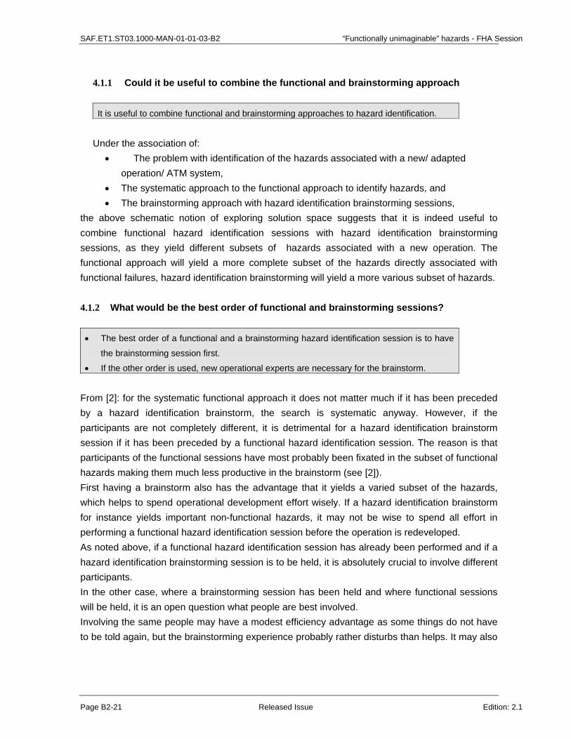
SAF.ET1.ST03.1000-MAN-01-01-03-B2 “Functionally unimaginable” hazards - FHA Session
Page B2-21 Released Issue Edition: 2.1
4.1.1 Could it be useful to combine the functional and brainstorming approach It is useful to combine functional and brainstorming approaches to hazard identification.
Under the association of:
• The problem with identification of the hazards associated with a new/ adapted operation/ ATM system,
• The systematic approach to the functional approach to identify hazards, and • The brainstorming approach with hazard identification brainstorming sessions,
the above schematic notion of exploring solution space suggests that it is indeed useful to combine functional hazard identification sessions with hazard identification brainstorming sessions, as they yield different subsets of hazards associated with a new operation. The functional approach will yield a more complete subset of the hazards directly associated with functional failures, hazard identification brainstorming will yield a more various subset of hazards. 4.1.2 What would be the best order of functional and brainstorming sessions? • The best order of a functional and a brainstorming hazard identification session is to have
the brainstorming session first.
• If the other order is used, new operational experts are necessary for the brainstorm.
From [2]: for the systematic functional approach it does not matter much if it has been preceded by a hazard identification brainstorm, the search is systematic anyway. However, if the participants are not completely different, it is detrimental for a hazard identification brainstorm session if it has been preceded by a functional hazard identification session. The reason is that participants of the functional sessions have most probably been fixated in the subset of functional hazards making them much less productive in the brainstorm (see [2]). First having a brainstorm also has the advantage that it yields a varied subset of the hazards, which helps to spend operational development effort wisely. If a hazard identification brainstorm for instance yields important non-functional hazards, it may not be wise to spend all effort in performing a functional hazard identification session before the operation is redeveloped. As noted above, if a functional hazard identification session has already been performed and if a hazard identification brainstorming session is to be held, it is absolutely crucial to involve different participants. In the other case, where a brainstorming session has been held and where functional sessions will be held, it is an open question what people are best involved. Involving the same people may have a modest efficiency advantage as some things do not have to be told again, but the brainstorming experience probably rather disturbs than helps. It may also
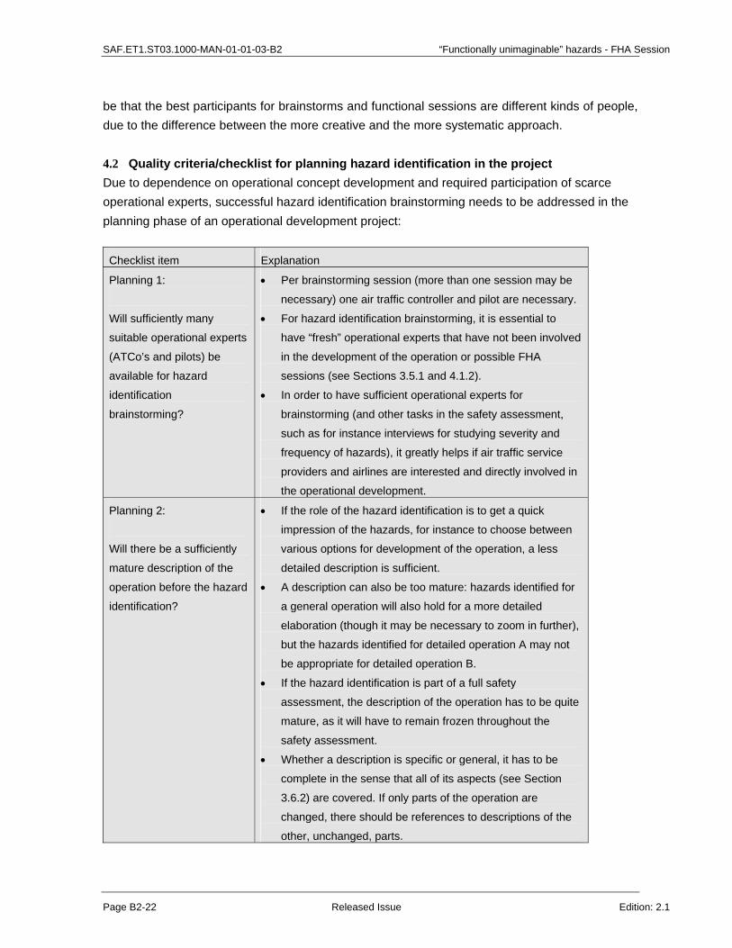
SAF.ET1.ST03.1000-MAN-01-01-03-B2 “Functionally unimaginable” hazards - FHA Session
Page B2-22 Released Issue Edition: 2.1
be that the best participants for brainstorms and functional sessions are different kinds of people, due to the difference between the more creative and the more systematic approach. 4.2 Quality criteria/checklist for planning hazard identification in the project Due to dependence on operational concept development and required participation of scarce operational experts, successful hazard identification brainstorming needs to be addressed in the planning phase of an operational development project: Checklist item Explanation
Planning 1:
Will sufficiently many
suitable operational experts
(ATCo’s and pilots) be
available for hazard
identification
brainstorming?
• Per brainstorming session (more than one session may be
necessary) one air traffic controller and pilot are necessary.
• For hazard identification brainstorming, it is essential to
have “fresh” operational experts that have not been involved
in the development of the operation or possible FHA
sessions (see Sections 3.5.1 and 4.1.2).
• In order to have sufficient operational experts for
brainstorming (and other tasks in the safety assessment,
such as for instance interviews for studying severity and
frequency of hazards), it greatly helps if air traffic service
providers and airlines are interested and directly involved in
the operational development.
Planning 2:
Will there be a sufficiently
mature description of the
operation before the hazard
identification?
• If the role of the hazard identification is to get a quick
impression of the hazards, for instance to choose between
various options for development of the operation, a less
detailed description is sufficient.
• A description can also be too mature: hazards identified for
a general operation will also hold for a more detailed
elaboration (though it may be necessary to zoom in further),
but the hazards identified for detailed operation A may not
be appropriate for detailed operation B.
• If the hazard identification is part of a full safety
assessment, the description of the operation has to be quite
mature, as it will have to remain frozen throughout the
safety assessment.
• Whether a description is specific or general, it has to be
complete in the sense that all of its aspects (see Section
3.6.2) are covered. If only parts of the operation are
changed, there should be references to descriptions of the
other, unchanged, parts.

SAF.ET1.ST03.1000-MAN-01-01-03-B2 “Functionally unimaginable” hazards - FHA Session
Page B2-23 Released Issue Edition: 2.1
4.3 Quality criteria/ checklist for preparing hazard identification Successful performance of hazard identification brainstorming needs careful preparation, typically to be started from a few weeks to months before the actual hazard identification brainstorming sessions. Checklist item Explanation
Preparing 1: Has a suitable moderator been arranged sufficiently early?
Moderation is a crucial function in hazard identification, and “ownership” of the way to moderate is crucial, too. Therefore: • A moderator should be involved several weeks before the
hazard identification brainstorms, such that he/ she can prepare him-/ herself for moderating in general (especially if he/ she is not experienced), and such that he/ she can do most of the preparation of the brainstorms.
• In principle, a safety analyst of the project would be an efficient choice of moderator.
Preparing 2: Have a suitable air traffic controller and pilot been arranged?
• Air traffic controller and pilot must NOT be involved in the development of the operation;
• Air traffic controller and pilot must NOT have participated in possible FHA sessions before;
• Match the kind of controller (ACC, Approach, ...) and the operation under assessment; vary with the kind of pilots.
• Air traffic controller and pilot in active service are preferred.
Preparing 3: Is there a description of the operation that is: • Sufficiently mature; • Understood by the
safety analysts and moderator; and
• Frozen in agreement with the developers?
• Concerning maturity, see the remarks under Checklist Planning 2 in Section 4.2.
Concerning understanding by the analysts: • At the beginning of the brainstorming session there will be
an overview presentation of the operation. This can be used to solve small questions. More fundamental questions have to be addressed much earlier.
It is important that the developers understand that for a good hazard identification or safety assessment, the operation under consideration cannot change in the mean time. The description of the operation for identification or assessment has therefore to be frozen in agreement with the developers.
Preparing 4:
Have hazards and hazard
categories for subtly
steering brainstorm been
prepared?
The moderator and/ or safety analysts should use
• Scoping brainstorms;
• Literature on related operations;
• Hazard databases; and
• Incident/ accident databases
to get an overview of the potential hazards of the operation and

SAF.ET1.ST03.1000-MAN-01-01-03-B2 “Functionally unimaginable” hazards - FHA Session
Page B2-24 Released Issue Edition: 2.1
use this, to make various categorizations according to
• Operational aspects;
• Conflict scenarios; and
• Groups of hazards with the same effect or cause.
The hazards and, more importantly, the categories can be used
during the brainstorm to steer subtly for completeness.
Preparing 5:
Have presentations for the
brainstorming session been
prepared?
It is suggested to give presentations about:
• The background of the project;
• The safety assessment method in which the hazard
identification is embedded;
• The operation to be brainstormed about; and
• Hazard identification brainstorming rules.
Except for the presentation about the operation, which may take
a little longer (say ten slides, 20 minutes) all presentations
should be very short (a few slides and minutes).
Preparing 6:
Have the practical things
about the brainstorm been
arranged?
Quiet room with:
• A round table configuration;
• Drinks;
• Notebook computer and beamer; and
• Flipchart, ...
4.4 Quality criteria/ checklist for evaluating the output of hazard identification The following questions yield indications of the quality of the output of hazard: Checklist Explanation
Evaluation 1: Have the hazards been understood correctly?
• The hazards identified in brainstorming sessions must have been carefully written down quickly after the session, and have been checked by the participants for correctness.
• Of course, during the brainstorm the moderator monitors this issue. However, the step from flipchart hazard summaries and notes to extensive minutes needs to be verified.
Evaluation 2:
Have sufficient hazards
been identified for all
prepared hazard
categories?
• If there are hazard categories for which no or only a few
hazards have been identified, why is that? In case several
categories have not been covered in the brainstorming
sessions due to a lack of time, additional brainstorming may
be necessary.
• To some extent this check can be done at the end of the
session.

SAF.ET1.ST03.1000-MAN-01-01-03-B2 “Functionally unimaginable” hazards - FHA Session
Page B2-25 Released Issue Edition: 2.1
Evaluation 3:
Have the brainstorms been
sufficiently reproductive?
• Have most hazards prepared via preliminary brainstorms,
literature, hazard database and accident/ incident database
been (re-)identified in the brainstorm?
Evaluation 4:
Have the brainstorms
yielded sufficient creative
hazards?
• If the operation is relatively new: have the brainstorms
yielded surprising hazards? If all identified hazards were
more or less foreseen by the moderator and safety analyst,
the brainstorm may well have been too restrictive, and the
full potential of creative air traffic controllers and pilots has
probably not been exploited maximally.
• If the operation is a modest adaptation of an operation for
which hazard have extensively been identified before,
brainstorms may yield only few new hazards, because there
are only a few new ones.
Evaluation 5:
What percentage of the
identified hazards is human
related?
Experience has shown that a significant part (at least half) of the
hazards is related to human operators. If the percentage is
much less, the brainstorm may have concentrated too much on
technical systems, for instance.
If there are significant shortcomings related to one or more of the last four checklist items, it should be considered to perform additional brainstorms.
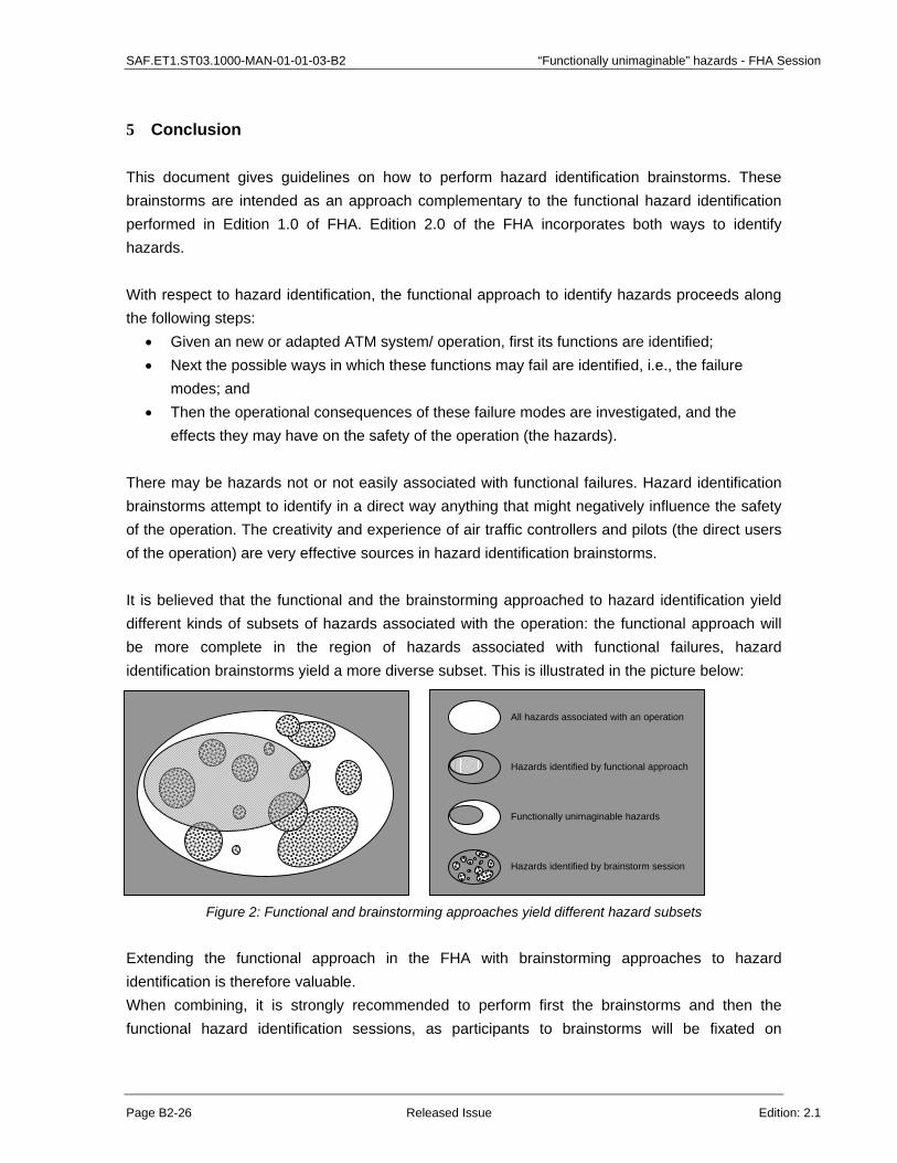
SAF.ET1.ST03.1000-MAN-01-01-03-B2 “Functionally unimaginable” hazards - FHA Session
Page B2-26 Released Issue Edition: 2.1
5 Conclusion
This document gives guidelines on how to perform hazard identification brainstorms. These brainstorms are intended as an approach complementary to the functional hazard identification performed in Edition 1.0 of FHA. Edition 2.0 of the FHA incorporates both ways to identify hazards. With respect to hazard identification, the functional approach to identify hazards proceeds along the following steps:
• Given an new or adapted ATM system/ operation, first its functions are identified; • Next the possible ways in which these functions may fail are identified, i.e., the failure
modes; and • Then the operational consequences of these failure modes are investigated, and the
effects they may have on the safety of the operation (the hazards). There may be hazards not or not easily associated with functional failures. Hazard identification brainstorms attempt to identify in a direct way anything that might negatively influence the safety of the operation. The creativity and experience of air traffic controllers and pilots (the direct users of the operation) are very effective sources in hazard identification brainstorms. It is believed that the functional and the brainstorming approached to hazard identification yield different kinds of subsets of hazards associated with the operation: the functional approach will be more complete in the region of hazards associated with functional failures, hazard identification brainstorms yield a more diverse subset. This is illustrated in the picture below:
Figure 2: Functional and brainstorming approaches yield different hazard subsets
Extending the functional approach in the FHA with brainstorming approaches to hazard identification is therefore valuable. When combining, it is strongly recommended to perform first the brainstorms and then the functional hazard identification sessions, as participants to brainstorms will be fixated on
Hazards identified by brainstorm session
All hazards associated with an operation
Functionally unimaginable hazards
Hazards identified by functional approach

SAF.ET1.ST03.1000-MAN-01-01-03-B2 “Functionally unimaginable” hazards - FHA Session
Page B2-27 Released Issue Edition: 2.1
functional hazards if they have been involved in functional hazard identification sessions before. Another advantage of this order is that, based on a broad overview of various kinds of hazards, it may occur that there may be better ways to proceed than performing an in-depth analysis of the functional hazards. It has turned out during literature search and talking to experts, that brainstorming science and techniques have developed far beyond what appears known in the world of ATM safety. It is expected that exploration and development of this knowledge can yield important further improvements in hazard identification for safety assessments in ATM.

SAF.ET1.ST03.1000-MAN-01-01-03-B2 “Functionally unimaginable” hazards - FHA Session
Page B2-28 Released Issue Edition: 2.1
References
[1] Bernard A. Nijstad; How the group affects the mind; PhD thesis University of Utrecht; Interuniversity Center for Social Science Theory and Methodology; 29 September 2000.
[2] Minutes of meeting with Bernard Nijstad about brainstorming (in Dutch), Hans de Jong, 17 September 2003.
[3] SAM PART IV ANNEX D: EUROCONTROL Experimental Centre, Review of Techniques to support the EATMP Safety Assessment Methodology, Main document and Technical Annex.
[4] EUROCONTROL Safety Regulatory Requirement - ESARR 4; Risk Assessment and Mitigation in ATM, Edition 1.0, 5 April 2001, available at
[5] EATMP Glossary, Edition 1.0, 1 August 2000, available at http://www.eurocontrol.int/eatmp/glossary/eatmp_glossary.pdf
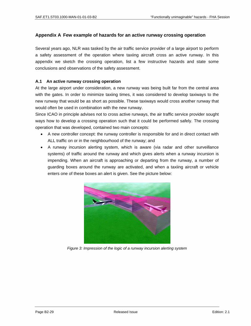
SAF.ET1.ST03.1000-MAN-01-01-03-B2 “Functionally unimaginable” hazards - FHA Session
Page B2-29 Released Issue Edition: 2.1
Appendix A Few example of hazards for an active runway crossing operation
Several years ago, NLR was tasked by the air traffic service provider of a large airport to perform a safety assessment of the operation where taxiing aircraft cross an active runway. In this appendix we sketch the crossing operation, list a few instructive hazards and state some conclusions and observations of the safety assessment. A.1 An active runway crossing operation At the large airport under consideration, a new runway was being built far from the central area with the gates. In order to minimize taxiing times, it was considered to develop taxiways to the new runway that would be as short as possible. These taxiways would cross another runway that would often be used in combination with the new runway. Since ICAO in principle advises not to cross active runways, the air traffic service provider sought ways how to develop a crossing operation such that it could be performed safely. The crossing operation that was developed, contained two main concepts:
• A new controller concept: the runway controller is responsible for and in direct contact with ALL traffic on or in the neighbourhood of the runway; and
• A runway incursion alerting system, which is aware (via radar and other surveillance systems) of traffic around the runway and which gives alerts when a runway incursion is impending. When an aircraft is approaching or departing from the runway, a number of guarding boxes around the runway are activated, and when a taxiing aircraft or vehicle enters one of these boxes an alert is given. See the picture below:
Figure 3: Impression of the logic of a runway incursion alerting system

SAF.ET1.ST03.1000-MAN-01-01-03-B2 “Functionally unimaginable” hazards - FHA Session
Page B2-30 Released Issue Edition: 2.1
A.2 Example hazards for the active runway crossing operation Two hazard identification brainstorming sessions where performed for the operation, and these were supplemented by hazard and incident database searches. A total of about 100 hazard was obtained. Although the database searches yielded a significant portion of the hazards, they were in general more vague and overlapping and less applicable and risky. A few example hazards:
h1: Runway incursion alerting system reacts too late or not at all; h2: System gives nuisance alert (for instance triggered by bird control); h3: Pilot misunderstands ATCo and takes off erroneously; h4: System generates alert, but ATCo does not react appropriately; h5: Pilot on the wrong frequency; h6: ATCo abuses alerting system for efficiency reasons; h7: Pilot is triggered by the elapsing of the prescribed wake vortex separation time with the
previous take-off and takes off without clearance; h8: Pilot on incorrect frequency and eventually takes off independently*; and h9: Pilot is mistaken/confused/lost due to taxiway complexity and accidentally enters runway.
*: Hazard h8 was obtained from an incident database; it is not clear how it could occur that the pilot took off independently. A.3 Some observations and conclusions The above list of hazards has been ordered with respect to the degree in which they are related to the functioning of the ATM system: The first two hazards would undoubtedly have been identified in functional hazard identification sessions. The next three are less directly connected with the functioning of the ATM system, but they are still quite conceivable and could have been identified by safety analysts alone. Routine violations are increasingly taken account of in hazard identifications according to FHA. The last three are of a more surprising nature, easily identified by operational experts (air traffic controllers and pilots) but hard to identify from a systematically functional point of view. In the last two hazards, functionally independent issues (communication failures in combination with a pilot being lost or taking off erroneous) turn out to be conceivable or actually occurring operational events. Note that the last hazard is not even directly related to crossing aircraft: the aircraft is mistaken/ confused/ lost due to taxiway complexity may not have had the intention to cross. In the risk assessment that followed, it turned out that the largest risks were related to hazards of the last kind. It was surprising to learn that the related risks were rather insensitive to performance of the alerting system and runway controller: even perfectly functioning alerting system and runway controller would not significantly decrease these risks! Or in more general

SAF.ET1.ST03.1000-MAN-01-01-03-B2 “Functionally unimaginable” hazards - FHA Session
Page B2-31 Released Issue Edition: 2.1
terms: it may well be that an operational safety risk cannot be decreased by better performance of technical systems. Later, an operation was developed with less active runway crossings, a simpler taxiway structure, adapted crossing procedures, measures to decrease the probability of communication problems due to wrong frequency, and without the alerting system. Hence it is important, especially in the first stages of the development of an operation to perform wide scope risk assessments, not restricted to ATM system functionality.

SAF.ET1.ST03.1000-MAN-01-01-03-B2 “Functionally unimaginable” hazards - FHA Session
Page B2-32 Released Issue Edition: 2.1
Appendix B Overview of hazard identification guidelines
B.1 The main activities, inputs and outputs In these guidelines, the main activities and goals related to hazard identification brainstorming are grouped and order as follows: Activity Goal
Plan • Tune operation definition and hazard identification
• Involve controllers and pilots via companies
Prepare • Arrange participants
• Prepare participants and context to make brainstorm maximally productive
Brainstorm • Obtain as many hazards as possible related to the operation
Evaluate • Judge if “all” of the operation’s hazards have been identified
In the picture below the main activities are ordered in their context, and their inputs and outputs (products) are indicated:
Plan
Prepare
Evaluate
Brainstorm
Descriptionof operation
Overview
of operation
Brainstorming
instructionsHazards andcategories
How tomoderate
List ofHazards
Theseguidelines
: Document
: Skill or knowledge
: Presentation
Legend
Qualityjudgement
Figure 4: Main activities, their ordering and their in- and outputs
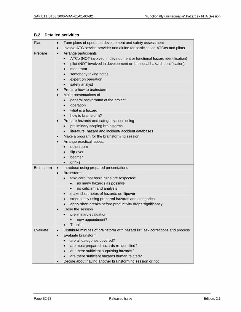
SAF.ET1.ST03.1000-MAN-01-01-03-B2 “Functionally unimaginable” hazards - FHA Session
Page B2-33 Released Issue Edition: 2.1
B.2 Detailed activities
Plan
• Tune plans of operation development and safety assessment • Involve ATC service provider and airline for participation ATCos and pilots
Prepare • Arrange participants • ATCo (NOT involved in development or functional hazard identification) • pilot (NOT involved in development or functional hazard identification) • moderator • somebody taking notes • expert on operation • safety analyst
• Prepare how to brainstorm • Make presentations of
• general background of the project • operation • what is a hazard • how to brainstorm?
• Prepare hazards and categorizations using • preliminary scoping brainstorms • literature, hazard and incident/ accident databases
• Make a program for the brainstorming session • Arrange practical issues:
• quiet room • flip-over • beamer • drinks
Brainstorm • Introduce using prepared presentations • Brainstorm
• take care that basic rules are respected: • as many hazards as possible • no criticism and analysis
• make short notes of hazards on flipover • steer subtly using prepared hazards and categories • apply short breaks before productivity drops significantly
• Close the session • preliminary evaluation
• new appointment? • Thanks!
Evaluate • Distribute minutes of brainstorm with hazard list, ask corrections and process • Evaluate brainstorm:
• are all categories covered? • are most prepared hazards re-identified? • are there sufficient surprising hazards? • are there sufficient hazards human related?
• Decide about having another brainstorming session or not

SAF.ET1.ST03.1000-MAN-01-01-03-C FHA – Hazard Effects
Page C-2 Released Issue Edition: 2.0
C
CHAPTER 3 GUIDANCE MATERIAL:
IDENTIFICATION OF HAZARD EFFECTS
1 SAFETY SIGNIFICANCE OF A HAZARD
The loss or degradation of system function(s) could impair the safety of the Air Navigation Service which the system provides or contributes towards, and subsequently, could impact aircraft operations.

FHA – Hazard Effects SAF.ET1.ST03.1000-MAN-01-01-03-C
Edition: 2.0 Released Issue Page C-3
A "Cause-Consequence" approach is proposed to determine the effects of the loss or degradation of system function(s).
The following sections identify some factors that could improve or worsen the consequences of hazards (due to system failure and/or external event occurrence(s)).
They are classified according to three major headings:
Effects on Air Navigation Services;
Exposure and;
Recovery.
1.1 Effects on Air Navigation Services
• Safety of Provided Air Navigation Services: Effects on the ability to provide or maintain safe Air Navigation Service(s).
• Working Conditions: Effects on the ATCOs and Flight Crew ability to cope with the reduction in functional capability, especially, impacts on their workload.
• Adverse Operational and Environmental Conditions: Effects on the ability for ATCO and/or Flight Crew to cope with adverse operational and environmental conditions.
• Functional Capabilities: Effects on the functional capabilities of the ground part of the ATM System and aircraft functional capabilities.
1.2 Exposure
• Exposure time: the amount of time the hazard exists.
• Number of exposed aircraft: Number of aircraft exposed to the hazards.
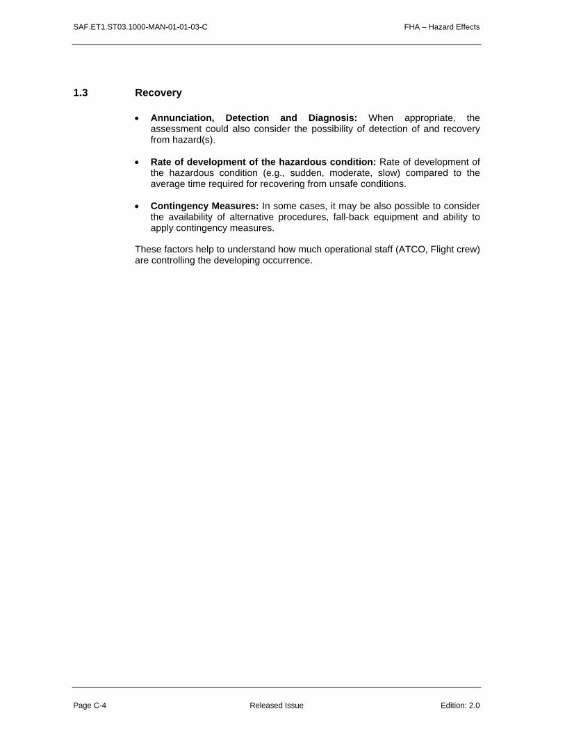
SAF.ET1.ST03.1000-MAN-01-01-03-C FHA – Hazard Effects
Page C-4 Released Issue Edition: 2.0
1.3 Recovery
• Annunciation, Detection and Diagnosis: When appropriate, the assessment could also consider the possibility of detection of and recovery from hazard(s).
• Rate of development of the hazardous condition: Rate of development of the hazardous condition (e.g., sudden, moderate, slow) compared to the average time required for recovering from unsafe conditions.
• Contingency Measures: In some cases, it may be also possible to consider the availability of alternative procedures, fall-back equipment and ability to apply contingency measures.
These factors help to understand how much operational staff (ATCO, Flight crew) are controlling the developing occurrence.

FHA – Severity Classification Scheme SAF.ET1.ST03.1000-MAN-01-01-03-D
Edition: 2.1 Released Issue Page D- 1
D
CHAPTER 3 GUIDANCE MATERIAL:
SEVERITY CLASSIFICATION SCHEME
1 INTRODUCTION
This guidance material provides some hints for practical and effective use of the Severity Classification Scheme within the FHA stage. The Severity Classification Scheme specified by the Safety Regulation Commission in ESARR4 provides only the “effect on operations”.
The examples of effects on operations provided in the ESARR4 Severity Classification Scheme are only examples and are not directly applicable to every system under assessment, as they refer generally to hazards at overall ATM level but not to lower level hazards such as at sub-system level.
Therefore as requested by ESARR4 (Appendix A-2, Page 17, 2nd note a)), the approach is to customise the Severity Classification Scheme in order to adequately

SAF.ET1.ST03.1000-MAN-01-01-03-D FHA – Severity Classification Scheme
Page D- 2 Released Issue Edition: 2.1
reflects the operational environment and make it meaningful in the context of the sub-system under assessment.
2 DEFINITIONS OF SEVERITY INDICATORS
To support the classification of hazard’s effect severity, 3 sets of severity indicators are proposed:
• Set 1: Effects on Air Navigation Service (includes airspace design (ASM), air traffic flow management (ATFM) and Air Traffic Management (ATM));
• Set 2: Exposure;
• Set 3: Recovery.
In each set, the different effects of hazards (as described in Guidance Material C) are ranked, in order to ease the assessment of the consequences on operations, including the effect on aircraft operations and the classification of hazard’s effect severity.
Table D-1 defines the various severity indicators for each class of hazard’s effect severity.
Note: Table D-1 includes some consideration of likelihood and credibility of hazard effect occurrence. These considerations mainly fit the second and fourth methods for setting safety objectives (See SAM-FHA Chapter 3 Annex G) which aim at identifying the worst credible effect of a hazard.
3 ORDER OF CONSIDERING THE SEVERITY INDICATORS
One or more sets of indicators may be used - there is some degree of overlap between them and the user should choose those which best suit their conceptual model of the system. Not all sets of indicators, or all indicators within a set, are necessarily relevant or meaningful in every assessment.
It is generally advisable to begin the assessment by considering the Set 1 - Effects on Air Navigation Service. Hazard(s) with no potential for significant consequences on safety can thus be eliminated at an early stage.
For the severity indicators in set 1, it is suggested that assessors work downwards through the rows in the table, since this broadly follows the most probable sequence of events resulting from a hazard in an Air Navigation System (See Barrier analysis FHA Chapter 3 - Guidance Material I).
One considers first the effects of the hazards on ability to provide safe Air Navigation Service, on ground ATM system and aircraft functional capabilities and on ATCOs and Flight Crew working conditions. Then one considers the ATCOs and Flight Crew ability to cope with adverse operational and environmental conditions.
The indicators in Set 2 - Exposure are more independent, and can be considered in any order. Duration of exposure may however need to be considered iteratively with the indicator ‘Rate of development’ within Set 3.
For the indicators in Set 3 - Recovery, it is suggested that assessors consider the
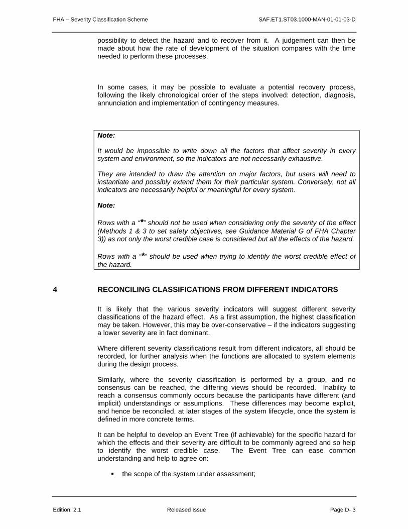
FHA – Severity Classification Scheme SAF.ET1.ST03.1000-MAN-01-01-03-D
Edition: 2.1 Released Issue Page D- 3
possibility to detect the hazard and to recover from it. A judgement can then be made about how the rate of development of the situation compares with the time needed to perform these processes.
In some cases, it may be possible to evaluate a potential recovery process, following the likely chronological order of the steps involved: detection, diagnosis, annunciation and implementation of contingency measures.
Note:
It would be impossible to write down all the factors that affect severity in every system and environment, so the indicators are not necessarily exhaustive.
They are intended to draw the attention on major factors, but users will need to instantiate and possibly extend them for their particular system. Conversely, not all indicators are necessarily helpful or meaningful for every system.
Note:
Rows with a “*” should not be used when considering only the severity of the effect (Methods 1 & 3 to set safety objectives, see Guidance Material G of FHA Chapter 3)) as not only the worst credible case is considered but all the effects of the hazard.
Rows with a “*” should be used when trying to identify the worst credible effect of the hazard.
4 RECONCILING CLASSIFICATIONS FROM DIFFERENT INDICATORS
It is likely that the various severity indicators will suggest different severity classifications of the hazard effect. As a first assumption, the highest classification may be taken. However, this may be over-conservative – if the indicators suggesting a lower severity are in fact dominant.
Where different severity classifications result from different indicators, all should be recorded, for further analysis when the functions are allocated to system elements during the design process.
Similarly, where the severity classification is performed by a group, and no consensus can be reached, the differing views should be recorded. Inability to reach a consensus commonly occurs because the participants have different (and implicit) understandings or assumptions. These differences may become explicit, and hence be reconciled, at later stages of the system lifecycle, once the system is defined in more concrete terms.
It can be helpful to develop an Event Tree (if achievable) for the specific hazard for which the effects and their severity are difficult to be commonly agreed and so help to identify the worst credible case. The Event Tree can ease common understanding and help to agree on:
the scope of the system under assessment;

SAF.ET1.ST03.1000-MAN-01-01-03-D FHA – Severity Classification Scheme
Page D- 4 Released Issue Edition: 2.1
the external mitigations means (barriers which are NOT part of the system under assessment);
the operational environment;
the mode of operation.
5 SOME CAUTIONS IN THE USE OF THE SEVERITY CLASSIFICATION SCHEME
Users are reminded to be cautious about the extent to which the Severity Classification Scheme is reliable upon:
• The Severity Classification Scheme is an aid to subjective judgement, not a rigid tool;
• The indicators are prompts, which help to ensure that all relevant factors have been taken into account, not rigidly defined parameters in a mathematical expression;
• The Severity Classification Scheme should be used iteratively through the development cycle - classification should be reviewed as functions are allocated to system elements and the development of these element progresses.

FHA – Severity Classification Scheme SAF.ET1.ST03.1000-MAN-01-01-03-D
Edition: 2.1 Released Issue Page D- 5
This page is intentionally left blank.

SAF.ET1.ST03.1000-MAN-01-01-03-D FHA – Severity Classification Scheme
Page D-6 Released Issue Edition: 2.1
Severity Class 1 [Most Severe]
2 3 4 5 [Least Severe]
Effects on Operations Accidents Serious Incidents Major Incidents Significant Incidents No Immediate Effect on Safety
SEVERITY INDICATORS SET1: EFFECTS ON AIR NAVIGATION SERVICE
Effect on Air Navigation Service within the area of responsibility
Total inability to provide or maintain safe service
Serious inability to provide or maintain safe service
Partial inability to provide or maintain safe service
Ability to provide or maintain safe but degraded service
No safety effect on service
ATCO and/or Flight Crew Working Conditions
Workload, stress or working conditions are such that they cannot perform their tasks at all
Workload, stress or working conditions are such that they are unable to perform their tasks effectively
Workload, stress or working conditions such that their ability is significantly impaired
Workload, stress or working conditions are such that their abilities are slightly impaired
No effect
Effect on ground ATM System and/or Aircraft Functional Capabilities
Total loss of functional capabilities Large reduction of functional capabilities
Significant reduction of functional capabilities
Slight reduction of functional capabilities
No effect
ATCO and/or Flight Crew Ability to Cope with Adverse Operational and Environmental Conditions *
Unable to cope with adverse operational and environmental conditions
Large reduction of the ability to cope with adverse operational and environmental conditions
Significant reduction of the ability to cope with adverse operational and environmental conditions
Slight reduction of the ability to cope with adverse operational and environmental conditions
No effect
Effect on Barrier model (See FHA Chapter 3 – GM I)
Inability for any “prevention”, “resolution” nor “recovery” of conflict situation.
Inability for “prevention” and/or “resolution” of conflict situation, however “recovery” possible.
Inability for “prevention” of conflict situation, “resolution” partially impaired.
“Prevention” of conflict situation impaired.
No effect
SEVERITY INDICATORS SET 2: EXPOSURE
Exposure time The presence of the hazard is almost permanent. Reduction of safety margins persists even after recovering from the immediate problem.
Hazard may persist for a substantial period of time
Hazard may persist for a moderate period of time.
Hazard may persist for a short period of time such that no significant consequences are expected.
Too brief to have any safety-related effect
Number of aircraft exposed / area of responsibility
All aircraft in the area of responsibility
All aircraft in several ATC Sectors Aircraft within a small geographic area or an area of low traffic density
Single aircraft No aircraft affected
SEVERITY INDICATORS SET 3: RECOVERY
Annunciation, Detection and Diagnosis * Undetected misleading indication. Ambiguous indication. Not easily detected. Incorrect diagnosis likely
May require some interpretation. Detectable. Incorrect diagnosis possible
Clear annunciation. Easily detected, reliable diagnosis
Clear annunciation. Easily detected and very reliable diagnosis
Contingency measures (other systems or procedures) available
No existing contingency measures available. Operators unprepared. Limited ability to intervene.
Limited contingency measures, providing only partial replacement functionality. Operators not familiar with procedures or may need to devise a new procedure at the time.
Contingency measures available, providing most of required functionality. Fall back equipment usually reliable. Operator intervention required, but a practised procedure within the scope of normal training
Reliable, automatic, comprehensive contingency measures
Highly reliable, automatic, comprehensive contingency measures
Rate of development of the hazardous condition, compared to the time necessary for annunciation, detection, diagnosis and application of contingency measures
Sudden. It does not allow recovery Fast Similar Slow Plenty of time available.
TABLE D-1 – EATMP SAM Severity Classification Scheme (* row not to be used only when looking at the WORST CREDIBLE CASE: Methods 2 & 4 to set Safety Objectives)

FHA – Severity Classification Scheme SAF.ET1.ST03.1000-MAN-01-01-03-D
Edition: 2.1 Released Issue Page D-7

SAF.ET1.ST03.1000-MAN-01-01-03-D FHA – Severity Classification Scheme
Page D-8 Released Issue Edition: 2.1
This page is intentionally left blank.
FHA – RCS SAF.ET1.ST03.1000-MAN-01-01-03-E
Edition: 2.1 Released Issue Page E-1
E
CHAPTER 3 GUIDANCE MATERIAL:
RISK CLASSIFICATION SCHEME
1 INTRODUCTION
This Guidance Material is further detailed into EUROCAE ED125 document that contains details on Risk Classification Scheme (RCS) definition, content (quantitative Safety Targets) and means to define National Regulatory RCS, ANSP RCS.
Note: ED125 proposes also means to quantify Safety Objectives, but ONLY for hazards at the scope of the Air Traffic Management Service Provision, based on the methods developed in FHA Chapter 3 Guidance Material G.
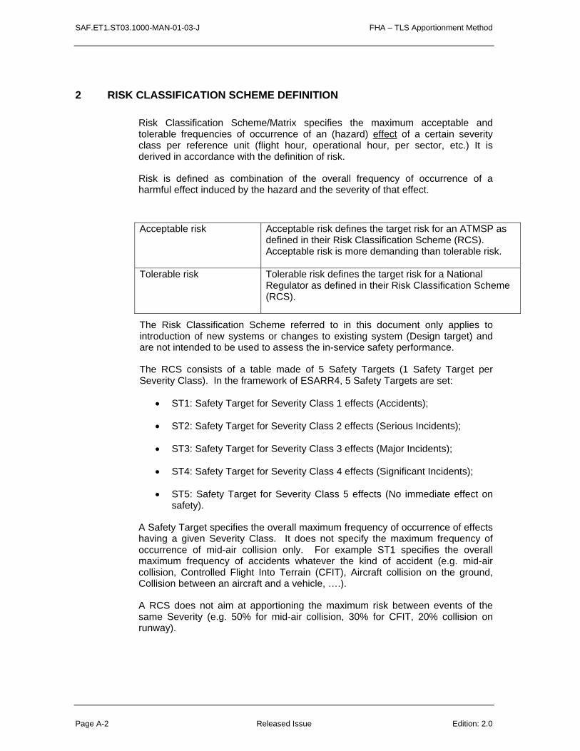
SAF.ET1.ST03.1000-MAN-01-03-J FHA – TLS Apportionment Method
Page A-2 Released Issue Edition: 2.0
2 RISK CLASSIFICATION SCHEME DEFINITION
Risk Classification Scheme/Matrix specifies the maximum acceptable and tolerable frequencies of occurrence of an (hazard) effect of a certain severity class per reference unit (flight hour, operational hour, per sector, etc.) It is derived in accordance with the definition of risk.
Risk is defined as combination of the overall frequency of occurrence of a harmful effect induced by the hazard and the severity of that effect.
Acceptable risk Acceptable risk defines the target risk for an ATMSP as defined in their Risk Classification Scheme (RCS). Acceptable risk is more demanding than tolerable risk.
Tolerable risk Tolerable risk defines the target risk for a National Regulator as defined in their Risk Classification Scheme (RCS).
The Risk Classification Scheme referred to in this document only applies to introduction of new systems or changes to existing system (Design target) and are not intended to be used to assess the in-service safety performance.
The RCS consists of a table made of 5 Safety Targets (1 Safety Target per Severity Class). In the framework of ESARR4, 5 Safety Targets are set:
• ST1: Safety Target for Severity Class 1 effects (Accidents);
• ST2: Safety Target for Severity Class 2 effects (Serious Incidents);
• ST3: Safety Target for Severity Class 3 effects (Major Incidents);
• ST4: Safety Target for Severity Class 4 effects (Significant Incidents);
• ST5: Safety Target for Severity Class 5 effects (No immediate effect on safety).
A Safety Target specifies the overall maximum frequency of occurrence of effects having a given Severity Class. It does not specify the maximum frequency of occurrence of mid-air collision only. For example ST1 specifies the overall maximum frequency of accidents whatever the kind of accident (e.g. mid-air collision, Controlled Flight Into Terrain (CFIT), Aircraft collision on the ground, Collision between an aircraft and a vehicle, ….).
A RCS does not aim at apportioning the maximum risk between events of the same Severity (e.g. 50% for mid-air collision, 30% for CFIT, 20% collision on runway).
FHA – RCS SAF.ET1.ST03.1000-MAN-01-01-03-E
Edition: 2.1 Released Issue Page E-3
An ATMSP should define its own Risk Classification Scheme, consistent with the National one, which adequately reflects the operational environment in which the ATMP operates. It means that the ATMSP RCS should satisfy, as a minimum, the National Risk Classification Scheme and includes:
• the contribution of the ATMSP to overall national ATM risk and
• an ambition factor (or safety margin factor) which represents the ratio between regulatory minimum and what the ATMSP accepts to generate as a risk.
The National Risk Classification Scheme provided by the National Safety Regulatory Authority should specify at least the maximum tolerable frequencies of ATM contributing to accidents and incidents at the level of national airspace, but the National RCS can not be used directly (an apportionment has to be done) by the ATMSP for setting the Safety Objectives for individual hazards when dealing with specific constituent part of the ATM System.
Sometimes, the National Risk Classification Scheme can not be used directly by an ATMSP as many ATMSPs may contribute to this National ATMSPs. However, ATMSPs should provide the link between their RCS and the National RCS.
The National risk has to be apportioned down to the lower levels, such as functions or sub-systems. This could be done different ways: per phase of flight, per function of the ATM System, etc.
Safety Target (ST) = The maximum acceptable frequency of occurrence of an effect.

SAF.ET1.ST03.1000-MAN-01-03-J FHA – TLS Apportionment Method
Page A-4 Released Issue Edition: 2.0
National Regulatory Risk Classification Scheme (RCS) has to be specified as follows:
Safety Target ECAC Regulator
Safety Target
National Regulator Safety Target
National Regulator AF
Max Safety Target
(/ flight hour) (/ flight hour)
ST1 1.55E-08 1.55 1E-08
ST2 1E-05 1 1E-05
ST3 1E-04 1 1E-04
ST4 1E-02 1 1E-02
ST5 n/a n/a n/a
Table 1: Specification of National Regulatory RCS
ATMSP Risk Classification Scheme (RCS) has to be specified as follows:
Safety Target ATMSP Safety Target
Recommended ATMSP AF Max Safety Target
(/ flight hour)
ST1 10 1E-09
ST2 10 1E-06
ST3 10 1E-05
ST4 10 1E-03
ST5 n/a n/a
Table 2: Specification of ATMSP RCS

FHA – RCS SAF.ET1.ST03.1000-MAN-01-01-03-E
Edition: 2.1 Released Issue Page E-5
The specification of RCS in accordance with ED-125 has to be performed as follows:
1. ECAC Regulator Safety Targets have to be adopted as the overriding maximum allowable Safety Targets;
2. A minimum National Regulator Ambition Factor (AF) of 1.55 has to be applied to Severity Class 1 and a minimum of 1 applied to severity classes 2, 3 and 4;
3. A minimum ATMSP Ambition Factor (AF) of 10 has to be applied to all National Regulator Safety Targets.
Table 1 and Table 2 explanatory notes:
1. ECAC Regulator Safety Target for Severity Class 1 is taken from ESARR4;
2. Safety Targets for Severity Class 2, 3 and 4 are set by ED-125 through consideration of data and expert judgment;
3. National Regulator Safety Target = ECAC Safety Target / National AF;
4. ATMSP Safety Target = National Regulator Safety Target / ATMSP AF;
5. ST5 is not provided in this document as this Target is not safety related (Severity Class 5: “no immediate effect on safety”);
6. Different AFs may be applied to different Severity Classes by National Regulators or ATMSP as required as long as these AFs comply with the minimum values as specified in Table 2.
This document assumes that National Regulators publish their National RCS in accordance with this document. If National Regulators have already published or will publish National RCS diverting from this document, then ATMSP have to check if their RCS complies with the published National Regulator RCS. This can be an issue only if the National Regulator publishes Safety Targets being more demanding than the ATMSP RCS as recommended in this document. In such case the ATMSP has to use the National Regulator Safety Target(s) being more demanding (e.g. ST2 = 1E-7 /fh) as input to set its own ATMSP RCS and decide the Ambition Factor for this (ese) specific Safety Target(s) (e.g. AF = 1 for ST2).

SAF.ET1.ST03.1000-MAN-01-01-03-E FHA – RCS
Page E-6 Released Issue Edition: 2.1
This page is intentionally left blank.

SAF.ET1.ST03.1000-MAN-01-01-03-F FHA - SOCS
Page F-2 Released Issue Edition: 2.0
F
CHAPTER 3 GUIDANCE MATERIAL:
SAFETY OBJECTIVE CLASSIFICATION SCHEME
Safety Objective Classification Scheme (SOCS) specifies the maximum acceptable frequency of occurrence of a hazard per reference unit (flight hour, operational hour, per sector, etc.) taking into account the severity of the worst credible hazard effect (amongst all hazard effects).
Safety Objectives are qualitative or quantitative statements that define the maximum frequency at which a hazard can be tolerated to occur.

FHA - SOCS SAF.ET1.ST03.1000-MAN-01-01-03-F
Edition: 2.0 Released Issue Page F-3
An example of quantitative Safety Objective Classification Scheme (SOCS) is given below (Table F-1).
Table F-1: quantitative SOCS
Note that all numbers and units in the example are fictitious. Maximum Acceptable frequency of
occurrence of Hazard (Safety Objective)
[Per Operational-hour]
Severity Class of the Worst Credible hazard effect
[as per ESARR4]
SO < 10-7 SC1
10–7 < SO < 10-5 SC2
10–5 < SO < 10-4 SC3
10–4 < SO < 10-3 SC4
10–3 < SO < 10-1 SC5
An example of a Qualitative Safety Objective Classification Scheme is given below (Table F-2).
Table F-2: qualitative SOCS
Maximum acceptable
frequency of hazard occurrence (Safety Objective)
Severity Class of the Worst Credible hazard effect
[as per ESARR4]
EXTREMELY RARE SC1
RARE SC2
OCCASIONAL SC3
LIKELY SC4
NUMEROUS SC5
A Safety Objective Classification Scheme can be defined either at ANS/ATM Organisation level or at Programme or Functional level. Consequently, an ANSP/ATMSP can have many SOCS.
Each SOCS is defined for the purpose of a specific (sub-)system under safety assessment and is applicable only for this specific (sub-)system.

SAF.ET1.ST03.1000-MAN-01-01-03-F FHA - SOCS
Page F-4 Released Issue Edition: 2.0
The ANSP/ATMSP has then the responsibility to ensure that these SOCS all together are consistent with the organisation Risk Classification Scheme (RCS, See Guidance Material E of FHA – Chapter 3).
Example: Background of aircraft airworthiness Safety Objective Classification Scheme
The approach of deriving such a scheme is based on the historically derived accident rate for aviation and the arbitrary assumption for the contribution of airworthiness equipment failure conditions to that rate, as well as the assumptions about the number of failure conditions that could generate the accident. (For airworthiness, failure condition can be considered as similar to “SAM-hazard” at the equipment-only and overall ATM levels)
JAR 25.1309 Scheme is based on following:
[JAR 25.1309] “Historical evidence indicated that the probability of a serious accident due to operational and airframe-related causes was approximately one per million hours of flight. Furthermore, about 10 percent of the total were attributed to Failure Conditions caused by the aeroplane's systems. It seems reasonable that serious accidents caused by systems should not be allowed a higher probability than this in new aeroplane designs. It is reasonable to expect that the probability of a serious accident from all such Failure Conditions be not greater than one per ten million flight hours or 1 x 10⁻⁷ per flight hour for a newly designed aeroplane. The difficulty with this is that it is not possible to say whether the target has been met until all the systems on the aeroplane are collectively analysed numerically. For this reason it was assumed, arbitrarily, that there are about one-hundred potential Failure Conditions in an aeroplane which could be Catastrophic. The target allowable Average Probability per Flight Hour of 1 x 10⁻⁷ was thus apportioned equally among these Failure Conditions, resulting in an allocation of not greater than 1 x 10⁻⁹ to each. The upper limit for the Average Probability per Flight Hour for Catastrophic Failure Conditions would be 1 x 10⁻⁹ which establishes an approximate probability value for the term "Extremely Improbable". Failure Conditions having less severe effects could be relatively more likely to occur.”
By adopting the order of magnitude of 10-2 between the severity classes, JAR 25.1309 specifies maximum tolerable rate of occurrence of single Failure Condition of certain severity:
Catastrophic 10-9 and less/ fh
Hazardous effect 10-7 – 10-9/ fh
Major effect 10-5 – 10-7/ fh
Minor effect 10-3 – 10-5/ fh
A similar approach could be developed for ATM environment by making some different assumptions about the contribution of ATM in the aviation accident risk and the number of ATM hazards that could generate accidents. Units to be used

FHA - SOCS SAF.ET1.ST03.1000-MAN-01-01-03-F
Edition: 2.0 Released Issue Page F-5
for expressing the probabilities should be considered as well, since flight hour may not be suitable for ATM systems in continuous use.

SAF.ET1.ST03.1000-MAN-01-01-03-G FHA – Safety Objectives
Page G-2 Released Issue Edition: 2.0
G
CHAPTER 3 GUIDANCE MATERIAL:
METHODS FOR SETTING SAFETY OBJECTIVES
Safety Objectives (SO) are qualitative or quantitative statements that define the maximum frequency at which a hazard can be accepted to occur.

FHA – Safety Objectives SAF.ET1.ST03.1000-MAN-01-01-03-G
Edition: 2.0 Released Issue Page G-3
1 MAKING WORST CREDIBLE CASE ASSUMPTIONS
The purpose of identifying the worst credible case is to specify the relevant level of stringency of Safety Objective: not over stringent (covering some “extreme” cases) and not too lenient (not covering “reasonable” cases).
To be consistent with the ‘bias towards safety’, assessors should ensure that their assessments make adequate allowance for worst credible case conditions.
It is often difficult to define the boundary between a worst credible case and one so dependent on the co-incidence of unrelated rare events that it should not be taken into account. There is no universally applicable set of rules for setting this boundary, but assessors may find the following guidance helpful in promoting a consistent approach.
A difference should be made between the worst case and the worst credible case.
The worst case identifies the effect that has the most severe consequences. This in many cases could be a Severity 1 (Accident). However, when trying to set a Safety Objective to define, design and operate an ATM system, taking into account this most severe effect could not always lead to set the most stringent safety objective, because the scenario leading to generate this or these Severity 1 effects are so unlikely (many and/or efficient mitigation means or barriers between the hazard and the effect).
In other words, the severity of the hazard effect should not be the only criteria to be taken into account to assess the worst credible case. The risk associated with this scenario leading to generate such an effect should be the criterion and a risk is made of the severity of such effect AND the likelihood of this effect to occur.
The worst credible case aims at identifying the highest contribution of a hazard to a high or the highest risk.
1.1 SAM Definitions
‘Worst’ means the most unfavourable conditions – e.g. extremely high levels of traffic or extreme weather disruption.
‘Credible’ implies that it is not unreasonable to expect to experience this combination of extreme conditions within the operational lifetime of the system so that such scenario leading to generate such an effect has to be considered.
Note1: Theses definitions are as per EATMP SAM.
Note2: The word “credible” could lead to difficulties of interpretation, as what is meant is: a combination being “a believable scenario” or “being reasonably pessimistic”. So it obviously includes a subjective part (which should be reduced as much as possible by provision of rationale, field experience data, ..) and

SAF.ET1.ST03.1000-MAN-01-01-03-G FHA – Safety Objectives
Page G-4 Released Issue Edition: 2.0
requires expert judgement. So other words such as “realistic” or “reasonable” could have been chosen instead of “credible”.
However, it was decided to keep this word as it is now being in use for a while.
1.2 Common Cause Analysis (CCA)
Common Cause Analysis is sub-divided into the following areas of study:
• Zonal Safety Analysis (ZSA): should examine each physical zone of the system under assessment to ensure that system installation and potential physical interference with adjacent systems do not violate the independence requirements of the system.
• Particular Risks Assessment (PRA): should examine those common events or influences that are outside the system under assessment but which may violate independence requirements. These particular risks lay also influence several zones at the same time, whereas zonal safety analysis is restricted to each specific zone;
• Common Mode Analysis (CMA): should provide evidence (for the SAM-FHA step) that the failures, failure modes or hazards assumed to be independent are truly independent.
Note: Common Cause Analysis are conducted a certain way during the FHA step of the SAM process to contribute to ensure that the assumptions and results of the FHA (Safety Objectives) are correct. Common Cause Analyses are then to be further continued at the relevant level for the other steps of the SAM (PSSA and SSA).
Note: the level of depth and completeness of the Common Cause Analysis should be commensurate with the stringency of Safety Objectives. So CCA should be extensive and complete for very stringent Safety Objective (for example: if qualitative Safety Objectives are such as “Extremely Rare” or “Rare”) and limited and/or partial for less stringent Safety Objectives (for example: if qualitative Safety Objectives are such as “Occasional ” or “Likely”).
Common Mode Analysis Guidance Material is available in SAE-ARP 4761 (Appendix I: ZSA, J: PRA but to be customised to ANS, K: CMA).
1.3 Consider Flight Phase and Adverse Conditions
Assessors should consider adverse circumstances within the normal range of conditions. The following should be considered:

FHA – Safety Objectives SAF.ET1.ST03.1000-MAN-01-01-03-G
Edition: 2.0 Released Issue Page G-5
• The most critical flight phase (failure effects may vary from flight phase to flight phase);
• Adverse environmental and operational conditions (Abnormal or degraded conditions in the system environment could impact the effects of failure occurrence(s), especially if these conditions occur relatively frequently)
1.4 Simultaneous, unrelated failures
In general, assessors need not assume that simultaneous, unrelated external events and failures occur to specify Safety Objectives.
However, assessing scenarii combining simultaneous unrelated failures could be performed to identify additional Safety Requirements bearing either on the Operational Environment or Safety Objectives bearing on the system under assessment when these combinations of unrelated failures are found as being probable.
1.5 What about the other effects?
Many effects may be identified and only one of them is leading to specify the Safety Objective of a specific hazard.
The other effects of a hazard will be also achieving an acceptable risk because they are covered by the worst credible case, as the worst credible case intends to specify the relevant level of stringency of the Safety Objective that make any hazard effect being acceptable risk.
However, sometimes hazards need to be split into many hazards in order to be more precise, for example:
Hazard Hazard Class (severity of the worst credible hazard
effect)
Loss for more than 2’ of [function A] in [Operational environment E]
2
versus
Hazard Hazard Class (severity of the worst credible hazard
effect)
Loss for less than 10” of [function A] in [Operational environment E]
4
Loss for more than 10” and less than 2’ of [function A] in [Operational environment E]
3
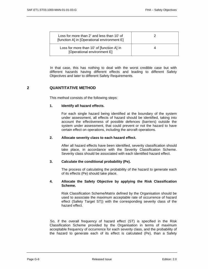
SAF.ET1.ST03.1000-MAN-01-01-03-G FHA – Safety Objectives
Page G-6 Released Issue Edition: 2.0
Loss for more than 2’ and less than 10’ of [function A] in [Operational environment E]
2
Loss for more than 10’ of [function A] in [Operational environment E]
4
In that case, this has nothing to deal with the worst credible case but with different hazards having different effects and leading to different Safety Objectives and later to different Safety Requirements.
2 QUANTITATIVE METHOD
This method consists of the following steps:
1. Identify all hazard effects.
For each single hazard being identified at the boundary of the system under assessment, all effects of hazard should be identified, taking into account the effectiveness of possible defences (barriers) outside the system under assessment, that could prevent or not the hazard to have certain effect on operations, including the aircraft operations.
2. Allocate severity class to each hazard effect.
After all hazard effects have been identified, severity classification should take place, in accordance with the Severity Classification Scheme. Severity class should be associated with each identified hazard effect.
3. Calculate the conditional probability (Pe).
The process of calculating the probability of the hazard to generate each of its effects (Pe) should take place.
4. Allocate the Safety Objective by applying the Risk Classification Scheme.
Risk Classification Scheme/Matrix defined by the Organisation should be used to associate the maximum acceptable rate of occurrence of hazard effect (Safety Target ST)) with the corresponding severity class of the hazard effect.
So, if the overall frequency of hazard effect (ST) is specified in the Risk Classification Scheme provided by the Organisation in terms of maximum acceptable frequency of occurrence for each severity class, and the probability of the hazard to generate each of its effect is calculated (Pe), than a Safety

FHA – Safety Objectives SAF.ET1.ST03.1000-MAN-01-01-03-G
Edition: 2.0 Released Issue Page G-7
Objective for the hazard itself is specified by dividing those two values for each different effect and choosing the most stringent one (the lowest figure) between the results,.
SO = min (STm / Pen ), n = (1,….x) , x = different hazard effects
m = (1,….5) 1, …5 are different severity classes
Note that when applying this method, the principle of the worst credible case is applied when setting the Safety Objective, by choosing the most stringent one, among different values calculated min (STm / Pen), taking into account not only the severity of the effects but also the probability of the effect as a consequence of the hazard.
Note: the number of hazards is to be taken into account (for example include it in Pe or divide STm / Pen by the number of hazards for that class of severity) in order to ensure that the sum of all Safety Objectives comply with Safety Targets.
The following figure illustrates the process of setting the Safety Objective using this method.
S
F
S
FS
F“FTA”
Causes “ETA” Consequences
“Pivotal” Event
S
F
S
FS
F
S
F
S
F
S
FS
F
S
F
Causes Consequences
HAZARD Effect A
Effect B Effect C
Effect D
Pe4Pe2Pe3
Pe1
Pe
Safety Target: Safety Target: Maximum acceptablefrequency of occurrence of Effectsfrequency of occurrence of Effects
SC4
SC2
SC3
SC1
ST2
ST3
ST1
ST4
RCS
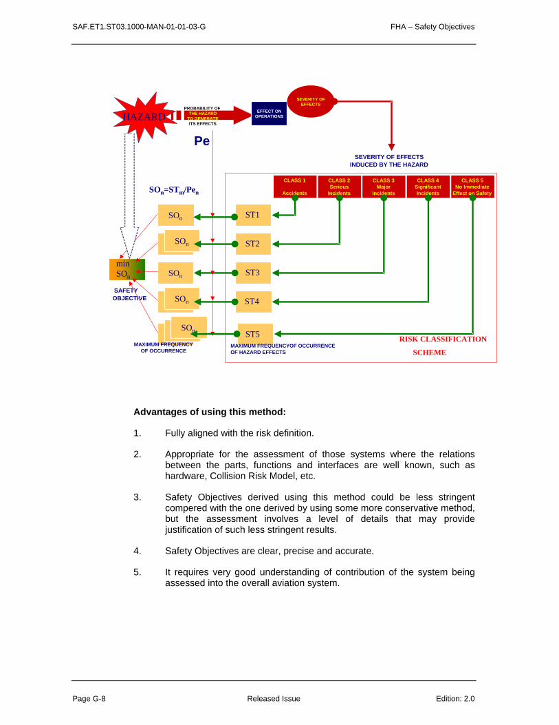
SAF.ET1.ST03.1000-MAN-01-01-03-G FHA – Safety Objectives
Page G-8 Released Issue Edition: 2.0
CLASS 1
Accidents
CLASS 2Serious
Incidents
CLASS 3Major
Incidents
CLASS 4SignificantIncidents
CLASS 5No Immediate
Effect on Safety
SEVERITY OF EFFECTSINDUCED BY THE HAZARD
PROBABILITY OFTHE HAZARD
TO GENERATE ITS EFFECTS
EFFECT ONOPERATIONS
SAFETY OBJECTIVE
SEVERITY OFEFFECTS
ST1
ST2
ST3
ST4
Pe
ST5
SOn
SOn
SOn
SO4
SO5 RISK CLASSIFICATION
SCHEME
minSOn
SOn=STm/Pen
SOn
SOn
SOn
MAXIMUM FREQUENCYOF OCCURRENCEOF HAZARD EFFECTS
MAXIMUM FREQUENCYOF OCCURRENCE
OF HAZARD
HAZARD
Advantages of using this method:
1. Fully aligned with the risk definition.
2. Appropriate for the assessment of those systems where the relations between the parts, functions and interfaces are well known, such as hardware, Collision Risk Model, etc.
3. Safety Objectives derived using this method could be less stringent compered with the one derived by using some more conservative method, but the assessment involves a level of details that may provide justification of such less stringent results.
4. Safety Objectives are clear, precise and accurate.
5. It requires very good understanding of contribution of the system being assessed into the overall aviation system.

FHA – Safety Objectives SAF.ET1.ST03.1000-MAN-01-01-03-G
Edition: 2.0 Released Issue Page G-9
Limitations of this method:
1. It is not always possible to calculate all the probabilities of hazards generating their effects, so assumptions could be needed in order to quantify them, especially when dealing with barriers relying on human or software.
2. It could be time and effort consuming to calculate all the probabilities.
3. It could be difficult to complete the list of barriers and scenarios that could lead to certain effects.
4. It could require additional effort to transform the units of measurement in order to perform certain calculations.
3 PRESCRIPTIVE METHOD
This method consists of the following steps:
1. Identify all the hazard effects.
For each single hazard being identified at the boundary of the system under assessment, all effects of hazard should be identified, taking into account the effectiveness of possible defences (barriers) outside the system under assessment, that could prevent or not the hazard to generate certain effect on operations, including the aircraft operations.
2. Allocate the severity class to each effect.
After all hazard effects have been identified, severity classification should take place, in accordance with the Severity Classification Scheme. Severity class should be associated with each identified hazard effect.
Note: In fact, this step is not always performed as very often, only step 3 is considered. However, the effectiveness of this method relies on the completeness of the identification of potential effects to make sure that the worst credible case is the correct one.
3. Apply the worst credible case scenario.
The worst credible effect in the given environment of operation should determine the severity class leading to setting of the Safety Objective, using expert judgement. It means that somehow the probability of the hazard leading to certain effect (Pe) has been taken into account when deciding the worst credible severity of the hazard effect.

SAF.ET1.ST03.1000-MAN-01-01-03-G FHA – Safety Objectives
Page G-10 Released Issue Edition: 2.0
4. Allocate the Safety Objective applying the Safety Objective Classification Scheme.
Safety Objectives are derived directly from the Safety Objective Classification Scheme (See Guidance Material F of this Chapter) that specifies the maximum acceptable frequency of occurrence of a hazard per unit (flight hour, operational hour, per sector, etc) using the severity of its worst credible effect.
The following figure illustrates the process of setting the Safety Objective using this method.
HAZARD
CLASS 1
Accidents
CLASS 2Serious
Incidents
CLASS 3Major
Incidents
CLASS 4SignificantIncidents
CLASS 5No Immediate
Effect on Safety
SEVERITY OF THE WORST CREDIBLEEFFECT LEADING TO SET THE SO
PROBABILITY OFTHE HAZARDGENERATING ITS EFFECTS
EFFECT ONOPERATIONS
SAFETYOBJECTIVE
MAXIMUM FREQUENCYOF OCCURRENCE
OF HAZARD
SEVERITY OFEFFECTS
SO
SO
SO
SO
SAFETY OBJECTIVE CLASSIFICATION SCHEMESO
WORST CREDIBLE CASE SCENARIO
Advantages of this method:
1. It’s easier to apply, requires less time, effort and resources, because it doesn’t require calculation of the probabilities of the hazard generating the effects (Pe). (It is assumed that they are somehow considered when deciding the severity class that will lead to set the Safety Objective).
2. It ensures harmonisation of the safety assessment process when applied on different system within the same Organisation.
3. It requires less elaboration of the assumptions made for the probabilities of the hazard generating its effects (Pe), since most of them are already embedded in the Safety Objective Classification Scheme.

FHA – Safety Objectives SAF.ET1.ST03.1000-MAN-01-01-03-G
Edition: 2.0 Released Issue Page G-11
(It is assumed that they are included in the Safety Objective Classification Scheme that, as a constant value that applies to all hazards having the severity allocated to their worst credible effect).
Limitations of this method:
1. The appropriateness of the Safety Objective Classification Scheme could lead to over-engineering or under-engineering of the system under assessment: As the same Safety Objective applies to whatever hazard as long as these hazards have the same worst credible effect severity. A Safety Objective Classification Scheme assumes a constant value of the probability of a hazard generating its effect (Pe) for all hazards of the same class (same worst credible effect severity). The answer whether SOCS leads to over or under engineering is known only years after its use being monitored.
2. It can be difficult to demonstrate the link of the SOCS with the organisation Risk Classification Scheme and the Regulatory minimum.
3. It focuses only on the most credibly severe effect of the hazard, without assessing in more details other less severe effects. Any risk has to be mitigated to a acceptable level including those for which the effect has a low level of severity.
4. It doesn’t require understanding the contribution of the system under assessment into ATM and overall aviation and the efficiency of the barriers outside the system under assessment (how they can, and more importantly can not, mitigate system hazards).
4 CRITICALITY METHOD
This method consists of the following steps:
1. Identify all the hazard effects.
For each single hazard being identified at the boundary of the system under assessment, all effects of hazard should be identified, taking into account the effectiveness of possible defences (barriers) outside the system under assessment, that could prevent or not the hazard to have certain effect on operations, including the aircraft operations.
2. Allocate the severity class to each effect.

SAF.ET1.ST03.1000-MAN-01-01-03-G FHA – Safety Objectives
Page G-12 Released Issue Edition: 2.0
After all hazard effects have been identified, severity classification should take place, in accordance with the Severity Classification Scheme. Severity class should be associated with each identified hazard effect.
3. Estimate the conditional probability (Pe).
The process of estimating the probability of the hazard to generate each of its effects (Pe) should take place.
4. Allocate the Safety Objective by applying Criticality Matrix.
Using the Criticality Matrix and depending on the severity class and the probability of the hazard effect, select the most stringent criticality out of all
Safety Objectives are identified for the hazard in a qualitative terms, as levels of criticality, such as A, B, C or D.
An example of the Criticality Matrix is given below.
Note that all numbers in the example are fictitious.
Example of Criticality Matrix.
Probability of the effect (Pe)
Severity of the Effect
1 2 3 4 5
1:1 .. 1:100 A A or B B or C C D
1:100 .. 1:10.000 A or B B or C C D D
1:10.000 .. 1:1.000.000 B or C C D D D
Less than 1:1.000.000 C D D D D
Levels of Criticality:
A – Very High B – High C – Medium D – Minor

FHA – Safety Objectives SAF.ET1.ST03.1000-MAN-01-01-03-G
Edition: 2.0 Released Issue Page G-13
Safety Objectives in terms of Criticality Levels (A, B, C or D) can be transformed in quantitative values, provided that the Organisation has defined its Safety Target (ST). In such case, this method becomes similar to the Quantitative method (see G.1), except that the probabilities of the hazard generating its effects (Pe) are estimated, rather than calculated.
The following figure illustrates the process of setting the Safety Objective using this method.
CLASS 1
Accidents
CLASS 2Serious
Incidents
CLASS 3Major
Incidents
CLASS 4SignificantIncidents
CLASS 5No Immediate
Effect on Safety
SEVERITY OF EFFECTSINDUCED BY THE HAZARD
EFFECT ONOPERATIONS
CRITICALITY LEVEL(SAFETY OBJECTIVE)
SEVERITY OFEFFECTS
A : VERY HIGH
B : HIGH
C : MEDIUM
D : MINOR
CRITICALITY MATRIX
HAZARDProbabilities of
a hazardgenerating its
effects
Pe
Figure: Safety Objective using Criticality matrix
Advantages of this method:
1. It’s more appropriate for assessing systems where precise quantification is difficult due to the nature of the system (software or human elements).
Limitations of this method:
1. This method is more appropriate for identification of Safety Requirements.
2. It requires more elaboration on assumption made on the probabilities of the hazard generating its effects, since they are estimated using expert judgement rather than calculated.
SAF.ET1.ST03.1000-MAN-01-01-03-G FHA – Safety Objectives
Page G-14 Released Issue Edition: 2.0
3. If the Safety Objectives expressed in terms of Criticality levels are not related to Safety Target and hence quantified, this method will have the limitations of the Qualitative method.(See G.5)
5 QUALITATIVE METHOD
This method consists of the following steps:
1. Identify all the hazard effects.
For each single hazard being identified at the boundary of the system under assessment, all effects of hazard should be identified, taking into account the effectiveness of possible defences (barriers) outside the system under assessment, that could prevent or not the hazard to generate certain effect on operations, including the aircraft operations.
2. Allocate the severity class to each effect.
After all hazard effects have been identified, severity classification should take place, in accordance with the Severity Classification Scheme. Severity class should be associated with each identified hazard effect.
Note: In fact, this step is not always performed as very often, only step 3 is considered. However, the effectiveness of this method relies on the completeness of the identification of potential effects to make sure that the worst credible case is the correct one.
3. Apply the worst credible case scenario.
The worst credible effect in the given environment of operation should determine the severity class leading to setting of the Safety Objective, using expert judgement. It means that somehow the probability of the hazard leading to certain effect (Pe) has been taken into account when deciding the worst credible severity of the hazard effect.
4. Allocate the Safety Objective applying Qualitative Safety Objective Classification Scheme.
Safety Objectives are derived directly from the Organisation Qualitative Safety Objective Classification Scheme which specifies, in qualitative terms, the maximum acceptable frequency of occurrence of a hazard using the severity of its worst credible effect.
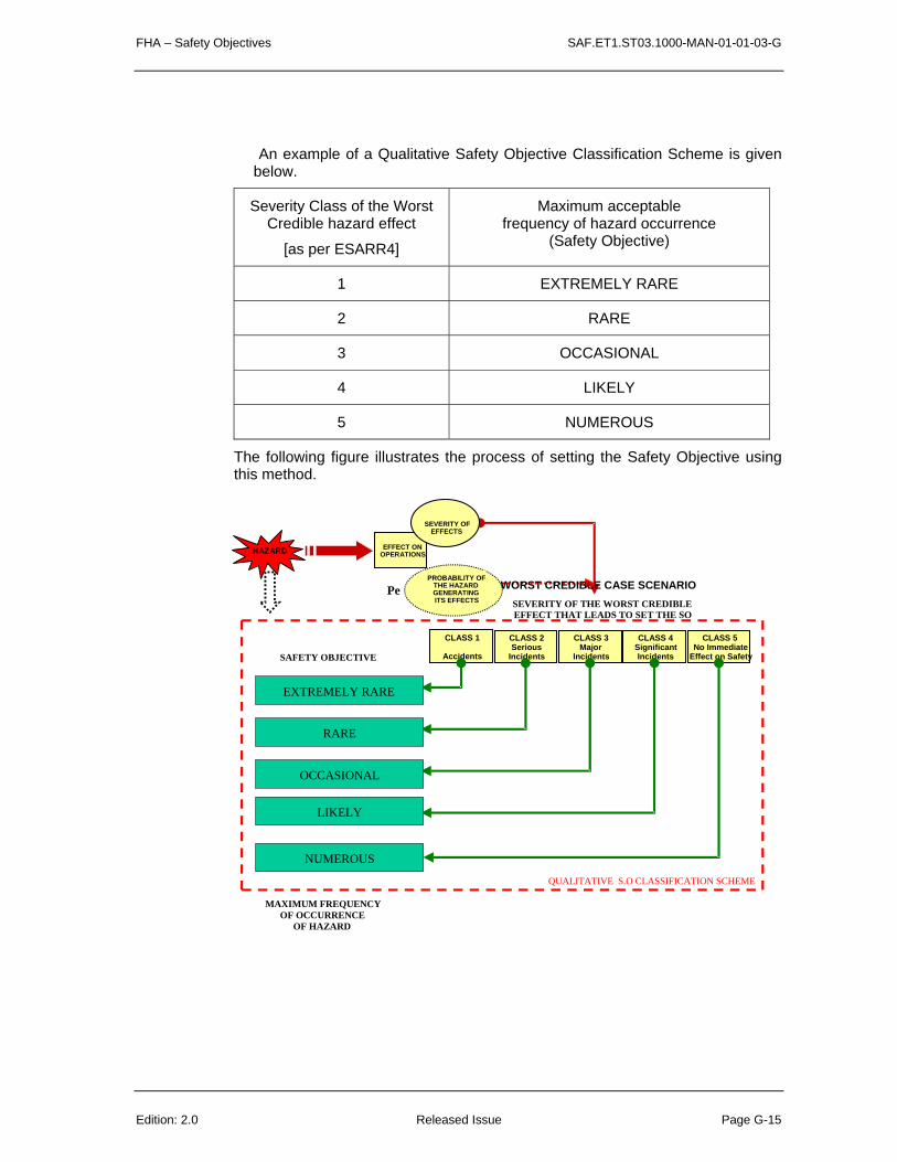
FHA – Safety Objectives SAF.ET1.ST03.1000-MAN-01-01-03-G
Edition: 2.0 Released Issue Page G-15
An example of a Qualitative Safety Objective Classification Scheme is given below.
Severity Class of the Worst Credible hazard effect
[as per ESARR4]
Maximum acceptable frequency of hazard occurrence
(Safety Objective)
1 EXTREMELY RARE
2 RARE
3 OCCASIONAL
4 LIKELY
5 NUMEROUS
The following figure illustrates the process of setting the Safety Objective using this method.
CLASS 1
Accidents
CLASS 2Serious
Incidents
CLASS 3Major
Incidents
CLASS 4SignificantIncidents
CLASS 5No Immediate
Effect on Safety
SEVERITY OF THE WORST CREDIBLEEFFECT THAT LEADS TO SET THE SO
PROBABILITY OFTHE HAZARDGENERATING ITS EFFECTS
EFFECT ONOPERATIONS
MAXIMUM FREQUENCYOF OCCURRENCE
OF HAZARD
SEVERITY OFEFFECTS
EXTREMELY RARE
RARE
OCCASIONAL
LIKELY
NUMEROUS
Pe
SAFETY OBJECTIVE
QUALITATIVE S.O CLASSIFICATION SCHEME
WORST CREDIBLE CASE SCENARIO
HAZARD

SAF.ET1.ST03.1000-MAN-01-01-03-G FHA – Safety Objectives
Page G-16 Released Issue Edition: 2.0
A definition of these qualitative categories could be: Numerous: This effect will certainly happen often throughout the system lifetime. Likely: This effect will certainly happen several times throughout the system lifetime. Occasional: This effect may happen sometimes throughout the system lifetime.
Rare: it is not expected to have such an effect more than exceptionally and in some specific circumstances throughout the system lifetime.
Extremely Rare: Such an effect is not expected to happen throughout the system lifetime.
Advantages of this method:
1. It is easy to apply.
2. It’s more appropriate for assessing systems where quantification is difficult or impracticable due to the nature of the system (software or human elements). In particular, it can be used as a first step, while waiting for being able later to quantify Safety Objectives.
3. It can be a useful intermediate step before being able to quantify Safety Objectives.
Limitations of this method:
1. As it may not be compliant with ESARR 4, it should be substantiated with the rationale explaining why quantification can not be performed.
2. When it is apportioned into Safety Requirements (especially for equipment), it doesn’t provide a clear and unambiguous target for the developers or suppliers of part(s) of the system accustomed to meeting quantified targets. Vendors of such equipment(s) tend to be familiar with quantified specifications, such as reliability/availability/integrity targets.
3. It’s not appropriate to show compliance where a quantitative Safety Target has already been specified at the organisation level (for example by the regulator and/or for the whole ANS or ATM organisation or ATC Centre).
4. It doesn’t ensure that the net effect on safety is positive in cases where it is expected that some factors of a new system may be allowed to increase the risk, in return for decreases elsewhere, and it is desired to
FHA – Safety Objectives SAF.ET1.ST03.1000-MAN-01-01-03-G
Edition: 2.0 Released Issue Page G-17
apportion the balance of benefits and disbenefits between the functions at this stage.
6 SAFETY OBJECTIVES SPECIFICATION
For each individual identified hazard, the Safety Objective specifies the maximum acceptable frequency of its occurrence.
Safety Objectives should be specified that way:
The frequency of [Hazard_Desc] in [Operational_Environment_Desc] shall be no greater than [Value].
The [Value] should be expressed accordingly to the scheme that has been chosen (see §G.2 to G.5 of this chapter)
Safety Objectives should be uniquely identified (SO-ACL-X) and traceable to hazard.
Some examples are given below.
• The frequency of delivering a corrupted, but credible, ATC clearance in the airspace under control by [RST] ATSU shall be no greater than 10-6 per clearance.
• The frequency of sending a mis-directed clearance message to one or more aircraft in the airspace under control by [DEF] ATSU shall be no greater than at least an order of magnitude better than that for voice communication.
• The frequency of a spurious alert at any Control Working Position in [ABC] ACC shall be no greater than once in a hundred operating hours.
• The frequency of a total loss of radar separation function for more than 1 minute in [XYZ] TMA sector shall be Extremely Rare.
• The frequency of losing flight level information for more than 10 seconds in sector [ZTV] shall be no greater than Occasional.
SAF.ET1.ST03.1000-MAN-01-01-03-G FHA – Safety Objectives
Page G-18 Released Issue Edition: 2.0
7 USE OF HISTORIC DATA
To define quantitative Safety Objectives, historic incident/accident data are often used to establish how much risk a particular system has faced in the past. Care is necessary when using historic data, for the following reasons:
• The more specific the system, the smaller will be the available dataset of incidents and accidents. The number of incidents and accidents specifically relevant to some systems may be too small to be relied upon. Users should take care to ensure an optimum balance between the relevance of the data and their statistical validity.
• Most incidents and accidents have more than one cause. In general, it is only for major accidents that causes are analysed and reported in detail. Hence it is notoriously difficult to apportion incident/accident causes to particular systems. The figures will also depend on whether one considers only primary causes or contributory factors as well.
Basing Safety Objectives on historic data is often the only practicable course, but users should be aware that it does not encourage optimisation of resources. High-risk parts of the operation may be allowed to continue using up a large fraction of the risk budget, when they could perhaps be made safer at reasonable cost. Conversely, expensive resources may continue to be devoted to controlling risks that are relatively small in reality. The iterative refinement of the FHA in later stages of system development should include positive consideration of where risk can most effectively be minimised.
SAF.ET1.ST03.1000-MAN-01-01-03-H FHA – Results records
Edition: 2.0 Released Issue Page H-2
H
CHAPTER 3 GUIDANCE MATERIAL:
RESULTS RECORDS

FHA – Results records SAF.ET1.ST03.1000-MAN-01-01-03-H
Edition: 2.0 Released Issue Page H - 3
1 HAZARD TABLE
The following table could be used to support the recording of the assessment of hazards. This table documents:
Hazard Identifier: Unique hazard identifier (ex: H-ACL-12)
Reference takes the form of H-[func]-[#], Where :
• H = Hazard;
• [func], if applicable, is a designator signifying a function of the system, and;
• [#] is a unique integer assigned to each hazard.
Function: name of the analysed function.
This column is not necessary if the list of hazards is presented per function of the system being assessed (instead of a table with all the hazards of all the functions of the system being assessed).
Hazard: for each function, description of hazard identified.
Effect of the hazard on operations: description of hazard effects on operations (ATCO, Flight crew, service provision, ..) including the effect on aircraft operations, considering adverse operational and environmental conditions.
Environmental Conditions: Includes list of reference designators for environmental conditions (mitigation means external to the system being assessed) applicable to substantiate hazard classification. These environmental conditions are requirements that shall be satisfied to operate tolerably safely the system being assessed. If these environmental conditions (requirements) are not satisfied, then the results of the safety assessment are no more valid and should be re-assessed.
For example: ACC or APP, voice as a primary means of communication when assessing Datalink, Radar control, OLDI availability, …
Severity Class: severity of the worst credible effect or of each hazard effect (if all separately identified) (assuming the listed environmental conditions).
This column content depends on the method chosen to specify Safety Objectives (See Guidance Material G). However, this is not the severity of the hazard itself (as a hazard has no severity).
Rationale/Remarks: rationale/remarks for its classification.

SAF.ET1.ST03.1000-MAN-01-01-03-H FHA – Results records
Edition: 2.0 Released Issue Page H-4
Abnormal event(s) reference: If some scenario of abnormal events have been elaborated in the framework of the system definition/description, then an additional column could be added as the last column with the reference to the abnormal event(s) (or these references can be put in the Rationale/Remark column) causing that hazard.(ex: AE-ACL-8) This abnormal event reference can be useful to validate the mode of operations, to consolidate safety and performance requirements and to specify Safety Requirements during PSSA.

FHA – Results Records SAF.ET1.ST03.1000-MAN-01-01-03-H
Edition: 2.0 Released Issue Page H - 5
Hazard Id
Function Hazard Effect on operations Environmental Conditions
Severity Class
Rationale/Remarks
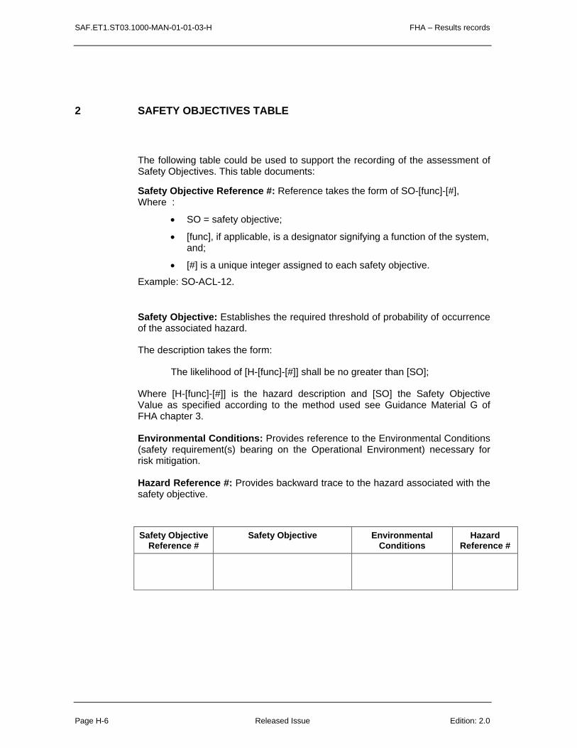
SAF.ET1.ST03.1000-MAN-01-01-03-H FHA – Results records
Page H-6 Released Issue Edition: 2.0
2 SAFETY OBJECTIVES TABLE
The following table could be used to support the recording of the assessment of Safety Objectives. This table documents:
Safety Objective Reference #: Reference takes the form of SO-[func]-[#], Where :
• SO = safety objective;
• [func], if applicable, is a designator signifying a function of the system, and;
• [#] is a unique integer assigned to each safety objective.
Example: SO-ACL-12.
Safety Objective: Establishes the required threshold of probability of occurrence of the associated hazard.
The description takes the form:
The likelihood of [H-[func]-[#]] shall be no greater than [SO];
Where [H-[func]-[#]] is the hazard description and [SO] the Safety Objective Value as specified according to the method used see Guidance Material G of FHA chapter 3.
Environmental Conditions: Provides reference to the Environmental Conditions (safety requirement(s) bearing on the Operational Environment) necessary for risk mitigation.
Hazard Reference #: Provides backward trace to the hazard associated with the safety objective.
Safety Objective Reference #
Safety Objective Environmental Conditions
Hazard Reference #
SAF.ET1.ST03.1000-MAN-01-01-03-I FHA – Barrier Analysis
Edition: 2.0 Released Issue Page I - 1
I
CHAPTER 3 GUIDANCE MATERIAL:
BARRIER ANALYSIS
This Guidance Material provides information on one possible way to perform a barrier analysis for ATM such as illustrated in the figure here after.

FHA – Barrier Analysis SAF.ET1.ST03.1000-MAN-01-01-03-II
Page I - 2 Released Issue Edition: 2.0
Potential Conflict
• Conflict trajectories • RWY incursion• Trajectory to the ground
Actual Conflict
• Separation infringement• MSA/H infringement• RWY Excursion
ATC
Aircr
aft
Reso
lution
Reso
lution
Proc
edur
al
Plan
ner
Dec
onfliction
Airsp
ace
Flow
Man
agem
ent
Man
agem
ent
Dec
onfliction
Pilot
Prov
iden
ce
ATC
Reco
very
Reco
very
Reco
very
Traffic Demand
• Traffic requiring air navigation services
PREVENTIONPREVENTION RESOLUTIONRESOLUTION RECOVERYRECOVERY
Accide
nt
In this barrier model described in the figure here above, the following terms mean:
Prevention of potential conflicts, like airspace design, flow management, procedural de-conflicting of the routes;
Resolution of potential conflicts, like ATCO instructions;
Recovery from actual conflicts, like ACAS supported avoiding action;
Traffic Volume (Demand). Risk of mid-air collision is roughly proportional to the square of the traffic, and risk of the collision with the ground or with obstacle on the ground is roughly linearly proportional to the traffic; and/or
Potential Conflict. Potential conflicts (Level Bust, Runway Incursion, Conflicting trajectories on the ground and in the air, Conflicting trajectory to the ground, Unauthorised Infringement of airspace) are adverse operational situations, which can become actual conflict (incident) if certain credible conditions are fulfilled (like presence of another aircraft in proximity); and /or
Actual Conflict: such as separation infringements, Minimum Safe Altitude Infringements, Runway Excursions etc.
This Barrier model is based on EUROCONTROL SPF (Strategic Performance Forecast) which is using a NATS study. This material does not intend to assess the safety aspects of an EATMP Programme but to help EUROCONTROL management to assess its safety importance in terms of potential for risk and benefit/improvement.
The following paragraphs provide guidance material for safety assessment based on a simple conceptual framework that shows where risk might arise in any ATM system. The model is intended to provide a relative assessment of safety (compared to an existing or baseline system) rather than a full quantification of risk. However it is possible that, with sufficient data, a quantified risk assessment using an adaptation of the basic model might be possible.
It should be stressed that the intention is not to produce a detailed and comprehensive Guidance Material for the Safety Assessment Methodology. It is rather to provide a simple, easy to apply method that is sufficiently flexible to be used to assess the high-level safety implications for any future concept.
SAF.ET1.ST03.1000-MAN-01-01-03-I FHA – Barrier Analysis
Edition: 2.0 Released Issue Page I - 3
The safety assessment framework is based on a high level conceptual model of how risk can arise in any ATM system. (For the purposes of this paper the term ATM system is taken in its widest possible sense and includes both ground and airborne elements.) The conceptual model is built around three types of safety-related events: Accidents, Incidents and Critical Events. The definitions for Accidents and Incidents are those given by ICAO and SRC, and are given in Table I-1. The safety targets for ATM systems are defined in terms of both accidents and incidents. The idea of a Critical Event has been developed specifically for use in this safety assessment framework. An example of a critical event is a pair of aircraft on conflicting paths, where failure to change the path of one or both aircraft would result in a loss of separation.
The principal assumption behind the conceptual framework is that for each type of accident there are associated incidents and, for each type of incident, associated critical events. For instance, for mid-air collisions the associated incident would be a loss of separation between a pair of aircraft and the associated critical event would be a pair of aircraft on conflicting paths. Different phases of flight have different characteristic accidents, incidents and critical events. It should be noted that the process described here does not cover one possible type of ATM related accident. In theory it would be possible for ATM to cause an accident by providing an instruction that resulted in an aircraft performing an unsafe manoeuvre not involving a conflict with another aircraft or object (for instance slowing down below stall speed). The framework does not yet take account of this type of problem.

FHA – Barrier Analysis SAF.ET1.ST03.1000-MAN-01-01-03-II
Page I - 4 Released Issue Edition: 2.0
ACCIDENT
(from ICAO)
An occurrence associated with the operation of an aircraft which takes place between the time any person boards the aircraft with the intention of flight until such time as all such persons have disembarked, in which:
a) a person is fatally or seriously injured as a result of:
• being in the aircraft, or
• direct contact with any part of the aircraft, including parts which have become detached from the aircraft, or
• direct exposure to jet blast,
except when the injuries are from natural causes, self-inflicted or inflicted by other persons, or when the injuries are to stowaways hiding outside the areas normally available to the passengers and crew; or
b) the aircraft sustains damage or structural failure which:
• adversely affect the structural strength, performance or flight characteristics of the aircraft, and
• would normally require major repair or replacement of the affected component
except for engine failure or damage, when the damage is limited to the engine, its cowlings or accessories; or for damages limited to propellers, wing tips, antennas, tires, brakes, fairings, small dents or puncture holes in the aircraft skin; or
c) the aircraft is missing or is completely inaccessible.
Note 1.-For statistical uniformity only, an injury resulting in death within thirty days of the date of the accident is classified as a fatal injury by ICAO.
Note 2.- An aircraft is considered to be missing when the official search has been terminated and the wreckage has not been located.
INCIDENT (from JAA)
An occurrence, other than an accident, associated with the operation of an aircraft, which affects or could affect the safety of operation.
CRITICAL EVENT
An occurrence in which an appropriate (ATM) action is required to avoid a loss of separation between two aircraft or between an aircraft and another object.
Table I-1: Definition of Terms

SAF.ET1.ST03.1000-MAN-01-01-03-I FHA – Barrier Analysis
Edition: 2.0 Released Issue Page I - 5
Table I-2 lists different types of ATM related accidents and their associated incidents and critical events.
PHASE OF FLIGHT
ACCIDENT INCIDENT CRITICAL EVENT
En-route Mid-air collision Loss of separation Conflicting aircraft pair
En – route, Approach or Departure
Wake Vortex Accident
Wake vortex encounter
One aircraft passes through a region where the vortex of a preceding aircraft might be
Approach or Departure
Controlled Flight Into Terrain on approach / departure
Deviation from approach / departure path leading to loss of separation with terrain or object on ground
Points on approach / departure path where deviation could lead to loss of separation.
Take-off or Landing
Runway collision
(between two aircraft or an aircraft and another vehicle)
Runway Incursion,
Uncleared Landing,
Uncleared Take-off
Conflicting:
Runway crossing, line up, landing or take-off
Taxi Taxiway collisions (between aircraft and another mobile vehicle)
Uncleared/Incorrect manoeuvre,
Incorrect clearance
Taxi conflict event
Taxi Taxi collision with static object (permanent or temporary)
Uncleared/Incorrect manoeuvre,
Incorrect clearance
Taxi past obstacle
Table I-2: ATM Accidents and Their Precursors
Within this conceptual framework the ATM system can minimise risk by controlling the number of critical events that occur, by preventing critical events developing into incidents and by stopping incidents from becoming accidents. Hence there are three safety-related functions of an ATM system:
• Critical Event Generation,
• Critical Event Resolution; and
• Incident Recovery.
Figure I-1 shows this high level framework schematically. Any of the three ATM safety functions can be affected by the introduction of an OI (Operational Improvement). The following sections of this paper describe simple models for each
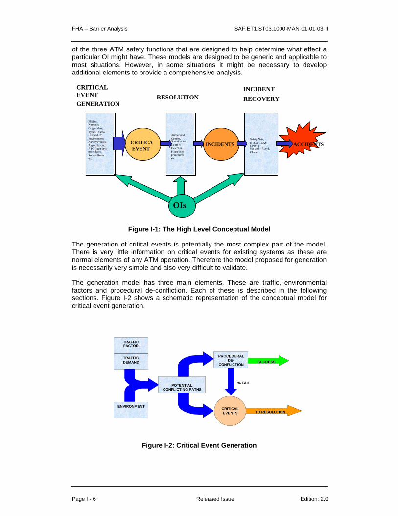
FHA – Barrier Analysis SAF.ET1.ST03.1000-MAN-01-01-03-II
Page I - 6 Released Issue Edition: 2.0
of the three ATM safety functions that are designed to help determine what effect a particular OI might have. These models are designed to be generic and applicable to most situations. However, in some situations it might be necessary to develop additional elements to provide a comprehensive analysis.
CRITICAEVENT
INCIDENTS ACCIDENTS
CRITICALEVENTGENERATION
RESOLUTIONINCIDENTRECOVERY
Flights:Numbers,Origin/ dest,Types, DiurnalDemand etcEnvironment:Airways/routes,Airport layout,ATC/flight deckprocedures,Sectors Rulesetc.
Air/GroundComms,Surveillance,ConflictDetection,Flight deckproceduresetc.
Safety Nets,(STCA, TCAS,GPWS),See and Avoid,Chance
OIs
Figure I-1: The High Level Conceptual Model
The generation of critical events is potentially the most complex part of the model. There is very little information on critical events for existing systems as these are normal elements of any ATM operation. Therefore the model proposed for generation is necessarily very simple and also very difficult to validate.
The generation model has three main elements. These are traffic, environmental factors and procedural de-confliction. Each of these is described in the following sections. Figure I-2 shows a schematic representation of the conceptual model for critical event generation.
TRAFFICFACTOR
TRAFFICDEMAND
ENVIRONMENT
POTENTIALCONFLICTING PATHS
PROCEDURALDE-
CONFLICTION
% FAIL
SUCCESS
TO RESOLUTIONCRITICALEVENTS
Figure I-2: Critical Event Generation

SAF.ET1.ST03.1000-MAN-01-01-03-I FHA – Barrier Analysis
Edition: 2.0 Released Issue Page I - 7
All critical events (by definition) involve aircraft interacting with other aircraft or objects. Therefore the most important element in generating critical events is the number of aircraft that pass through the ATM system. Most OIs will not in themselves change the traffic levels. If the traffic levels do change, the effect on the number of critical events will depend on whether they involve interactions between pairs of aircraft or between aircraft and other objects.
If the critical event of interest is conflicts between pairs of aircraft then the number of events will increase with the square of the traffic flow. If interactions between aircraft and other objects is of interest then this type of critical event can be expected to increase linearly with traffic. Within the model this difference is included using a parameter called the Traffic Factor. The traffic factor takes the value 2 for critical events involving pairs of aircraft and 1 otherwise.
There are many other factors that will also affect the generation of critical events. These include, but are not limited to:
• Separation Minima,
• Other Traffic (at airports),
• Airspace Design,
• Taxiway/Runway Design (at airports),
• Ground Obstacles.
Together all of these elements are described as environmental factors. If an OI is expected to change any of these factors then it will be necessary to estimate how this change might affect the number of critical events. It is not possible to provide a fully generic method for taking account of these environmental factors and each OI will need to be considered separately.
In order to include the effect of environmental factors it is necessary to estimate what the relative number of critical events will be after the implementation of the OI (with the same traffic).
In some OIs, systemisation might be used to reduce conflicts between aircraft. This can be achieved by providing flights with detailed de-conflicted routes, either on a flight by flight basis or by the application of general rules (the use of Standard Instrument Departure (SID) routes is a common example of this). This type of de-confliction is described in the model as procedural de-confliction.
Two parameters are required for procedural de-confliction:
• The proportion of critical events that are resolved by procedural de-confliction process; and
• The proportion of time that the process fails (either because of an error/inaccuracy in the de-confliction or due to failure of an aircraft to follow.
In order to link Critical Events to Incidents a model of the key elements in the resolution process is required. Resolution can be thought of as a four-phase process as follows:

FHA – Barrier Analysis SAF.ET1.ST03.1000-MAN-01-01-03-II
Page I - 8 Released Issue Edition: 2.0
• Detect the Critical Event
• Develop a Solution
• Deliver the Solution
• Execute the Solution
Figure I-3 shows the model for resolution schematically.
DETECT SOLVE DELIVER EXECUTE
RESOLUTION FUNCTION
FAILURES
INCIDENTS
HUMAN
MACHINE
SOFTWARE
MACHINE
HUMAN
MACHINE
SOFTWARE
HUMAN
MACHINE
SOFTWARE
HUMAN
MACHINE
SOFTWARE
OIs
SUCCESS
CRITICALEVENTS
Figure I-3: The Resolution Process
For example, in a tactical radar environment a controller would detect a pair of aircraft on conflicting paths using the radar display system, then determine how to solve the conflict and finally deliver appropriate instructions to the pilot(s) of the aircraft. The pilot(s) would then execute the solution by changing the path of the aircraft. A failure in any of these stages of resolution is assumed to lead to an incident. (This is of course not entirely true, for instance a pilot might make an error in execution that does not lead to an incident, but this factor will make little difference in most practical applications.)
Each of the resolution functions could be undertaken by a combination of human operators, equipment and software systems. In order to assess the impact of an OI on the resolution function some understanding of how this process works in the current system (or a baseline system) is required. An OI will only change the resolution function if either the type of critical event changes (for instance a change in the geometry of conflicts making them more difficult to detect) or if one or more of the resolution functions are affected.
If the OI is expected to alter resolution it will be necessary to have some understanding of how it works in the baseline system and the relative importance of each of the resolution functions. It should be possible to categorise incidents according to which element of the resolution process failed and then make some estimates of how these relative failure rates will change with the introduction of the OI.
For some OIs there may not be any data on performance available from specifications or simulations. In this case it will be necessary to use approximations. The SPF Safety Group agreed the following simple guidelines, based on their experience of safety assessments. If the task involves a human task the failure rate can be assumed to be between 10-3 and 10-4. If it involves a complex software

SAF.ET1.ST03.1000-MAN-01-01-03-I FHA – Barrier Analysis
Edition: 2.0 Released Issue Page I - 9
system a failure rate of 10-5 can be used. If it is a well proven mechanical system or a simple software system a failure rate of 10-6 can be used. If a task involves more than one element then the value for the least reliable of the elements should be used. For instance, if the detection function involves a radar system detecting an aircraft (10-6), a software system processing and displaying the information to a controller (10-5) and a controller using the radar display to detect a conflict (10-4) then the failure rate is 10-4 . These are clearly only very crude values and it should be possible to model most systems more accurately using human factors analysis, fault trees etc.
A large percentage of all ATM incidents involve human error either as a causal or contributory factor. In the resolution process, the human operator has a significant role to play in the detection of the critical event, the development of a solution, the delivery of the solution, and the execution of that solution. For this reason, it is necessary to ensure that the failure rate of the human operator is considered when attempting to evaluate the impact of an operational improvement on safety.
In order to ensure that the contribution of human error is adequately considered, it is necessary to determine the ways in which the operator can fail, and the frequency with which these failures are likely to occur.
This section describes each of these processes in turn, beginning with the determination of the ways in which human operators can fail.
A great deal of work has been undertaken in the last three years by EUROCONTROL and NATS to develop tools and methodologies for the analysis of human error in ATM incidents. The general principles involved in such methodologies are the identification of the forms of human error that occur as part of an incident, and the decomposition of these errors to determine the psychological mechanisms behind the error, and hence the reasons why the errors occur.
With regard to the development of a model of human error for the Strategic Performance Framework, such research provides a great deal of information on how human operators can fail. At a high level, errors fall into a number of categories associated with the task that is being performed (e.g. radar monitoring, strip handling, etc.). Each of these errors can have a number of underlying causes (e.g. judgement, planing or decision-making failure, perception and vigilance failures). The ultimate cause of an error is the psychological mechanism that results in the operator making an error. Such mechanisms include perceptual tunnelling (when the operator focuses on one particular situation at the expense of all others) and information processing failure (where the operator’s information processing system is unable to cope with the type or quantity of information presented).
For the purposes of considering the human operator as part of the overall assessment of safety, it is not necessary to consider the underlying psychological causes. For a reasonable estimate of how the operator can fail it is adequate to derive an approximate probability of task errors.
For the purposes of the analysis of human errors in ATM incidents, a taxonomy has been developed for task errors, which is shown in Table I-3 below, alongside the relevance of each error type to the stages of the resolution process.

FHA – Barrier Analysis SAF.ET1.ST03.1000-MAN-01-01-03-II
Page I - 10 Released Issue Edition: 2.0
Task Error Detect Solve Deliver Execute
Separation Error
Controller-Pilot Communications Error Radar Monitoring Error Aircraft Observation / Recognition Error (TWR Only)
Co-ordination Error
Flight Progress Strip Usage Error
Control Room Communications Error
Handover / Takeover Error
Aircraft Transfer Error
Operational Materials Checking Error
HMI Input & Functions Use Error Training, Supervision or Examining Error
Table I-3: Task Errors and Applicability to the Resolution Process
An analysis of one year's worth of AIRPROX data was conducted on these error categories to determine the approximate frequency of each error type. Published AIRPROX data from 1997 relating to ATC errors in civil airspace were used, over which period there were 1,179,000 civil traffic movements.
Table I-4 shows the number of errors observed in each category along with an approximate error probability per traffic movement.
Task Error Number Probability Separation Error 0 0 Controller-Pilot Communications Error 55 4.66 x 10⁻²
Radar Monitoring Error 14 1.19 x 10⁻² Aircraft Observation / Recognition Error (TWR Only) 0 0 Co-ordination Error 4 3.39 x 10⁻³ Flight Progress Strip Usage Error 8 6.79 x 10⁻³ Control Room Communications Error 2 1.70 x 10⁻³ Handover / Takeover Error 2 1.70 x 10⁻³ Aircraft Transfer Error 0 0 Operational Materials Checking Error 0 0 HMI Input & Functions Use Error 1 8.48 x 10⁻⁴ Training, Supervision or Examining Error 18 1.53 x 10⁻²
Table I-4: Number of Observed Errors in 1997, and Approximate Error Probability.
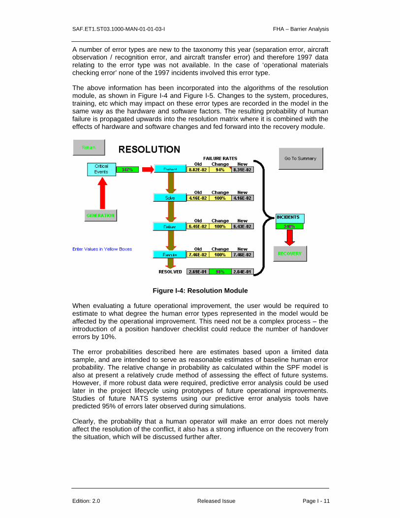
SAF.ET1.ST03.1000-MAN-01-01-03-I FHA – Barrier Analysis
Edition: 2.0 Released Issue Page I - 11
A number of error types are new to the taxonomy this year (separation error, aircraft observation / recognition error, and aircraft transfer error) and therefore 1997 data relating to the error type was not available. In the case of ‘operational materials checking error’ none of the 1997 incidents involved this error type.
The above information has been incorporated into the algorithms of the resolution module, as shown in Figure I-4 and Figure I-5. Changes to the system, procedures, training, etc which may impact on these error types are recorded in the model in the same way as the hardware and software factors. The resulting probability of human failure is propagated upwards into the resolution matrix where it is combined with the effects of hardware and software changes and fed forward into the recovery module.
Figure I-4: Resolution Module
When evaluating a future operational improvement, the user would be required to estimate to what degree the human error types represented in the model would be affected by the operational improvement. This need not be a complex process – the introduction of a position handover checklist could reduce the number of handover errors by 10%.
The error probabilities described here are estimates based upon a limited data sample, and are intended to serve as reasonable estimates of baseline human error probability. The relative change in probability as calculated within the SPF model is also at present a relatively crude method of assessing the effect of future systems. However, if more robust data were required, predictive error analysis could be used later in the project lifecycle using prototypes of future operational improvements. Studies of future NATS systems using our predictive error analysis tools have predicted 95% of errors later observed during simulations.
Clearly, the probability that a human operator will make an error does not merely affect the resolution of the conflict, it also has a strong influence on the recovery from the situation, which will be discussed further after.
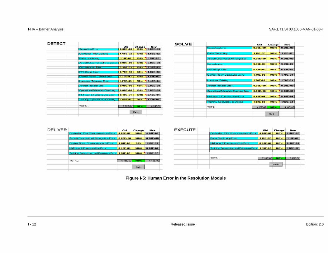
FHA – Barrier Analysis SAF.ET1.ST03.1000-MAN-01-03-II
I - 12 Released Issue Edition: 2.0
Figure I-5: Human Error in the Resolution Module

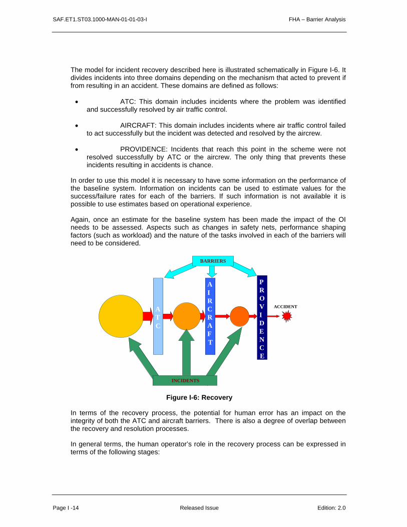
SAF.ET1.ST03.1000-MAN-01-01-03-I FHA – Barrier Analysis
Page I -14 Released Issue Edition: 2.0
The model for incident recovery described here is illustrated schematically in Figure I-6. It divides incidents into three domains depending on the mechanism that acted to prevent if from resulting in an accident. These domains are defined as follows:
• ATC: This domain includes incidents where the problem was identified and successfully resolved by air traffic control.
• AIRCRAFT: This domain includes incidents where air traffic control failed to act successfully but the incident was detected and resolved by the aircrew.
• PROVIDENCE: Incidents that reach this point in the scheme were not resolved successfully by ATC or the aircrew. The only thing that prevents these incidents resulting in accidents is chance.
In order to use this model it is necessary to have some information on the performance of the baseline system. Information on incidents can be used to estimate values for the success/failure rates for each of the barriers. If such information is not available it is possible to use estimates based on operational experience.
Again, once an estimate for the baseline system has been made the impact of the OI needs to be assessed. Aspects such as changes in safety nets, performance shaping factors (such as workload) and the nature of the tasks involved in each of the barriers will need to be considered.
ATC
AIRCRAFT
PROVIDENCE
INCIDENTS
ACCIDENT
BARRIERS
Figure I-6: Recovery
In terms of the recovery process, the potential for human error has an impact on the integrity of both the ATC and aircraft barriers. There is also a degree of overlap between the recovery and resolution processes.
In general terms, the human operator’s role in the recovery process can be expressed in terms of the following stages:

SAF.ET1.ST03.1000-MAN-01-01-03-I FHA – Barrier Analysis
Edition: 2.0 Released Issue Page I - 15
• The operator must detect the situation. The situation may be detected by the controller directly, by another controller, by an automated ATC system;
• The controller must have developed an effective solution to the situation, which must be delivered to the pilots(s) involved in a timely and effective manner;
• The pilot must react appropriately in compliance with transmitted instructions in a timely manner.
Within this process there are two broad types of barrier in operation. Firstly there is the human barrier, characterised by the detection and resolution of the incident by human operators without the need for automated systems. Examples of the human barriers include detection by the controller, timely and accurate compliance by the pilot, and further down the line successful see and avoid action by the pilot.
Secondly, there are automated barriers that serve to alert the user to impending problems. In the event that the human barrier fails at any point, the automated barrier is used to initiate the detection process. At present, ATM safety nets are only used to aid detection, not to assist in resolution.
It should be noted that by the time a safety net has drawn the attention of the operator to a problem, the time pressure to derive, deliver and execute the solution will be far greater than if the operator had detected the problem without assistance. This needs to be considered when examining the recovery process.
The estimated probability that a controller will fail to detect a potential conflict prior to STCA activation is 1.19 x 10⁻². Def Stan 00-56 (Ref. 6) suggests that the probability of an error in decision making under increased stress levels (e.g. under additional time pressure following STCA activation) tends to be between 2 x 10⁻¹ and 3 x 10⁻¹. In other words, as stress levels increase, the probability of failure increases by a factor of 16 to 25.
An analysis has not been performed to date to determine the probability of human failure following STCA activation and comparing this figure to the probability of failing to detect the conflict earlier. Therefore it is not possible to determine the validity of the Def Stan 00-56 estimate in the ATC environment. It is recommended that such an estimate be obtained for use in the evaluation of the ATC barrier.
When considering the effectiveness of the ATC barrier, the analyst should bear in mind the results of the Resolution module. In particular, care should be taken to ensure that any changes that affect human error probability are considered not only as part of resolution, but also as part of recovery.

FHA - Evaluation activities SAF.ET1.ST03.1000-MAN-01-01-04-A-B-C
Edition: 2.1 Released Issue Page A-B-C - 1
A B C
CHAPTER 4 GUIDANCE MATERIAL
FHA Evaluation Activities
1 Introduction
This chapter gives guidance on verifying and validating a Functional Hazard Assessment (FHA).
This guidance is meant to be used with the SAM and aims to avoid duplication. For the most part, the guidance gives references to specific parts of the SAM but there are occasional quotes to reduce the reader’s time spent searching for information.

FHA - Evaluation activities SAF.ET1.ST03.1000-MAN-01-01-04-A-B-C
Edition: 2.1 Released Issue Page A-B-C - 2
2 Objectives of the FHA The FHA process develops system Safety Objectives, defining the maximum frequency at which hazards can be accepted to occur.
3 How to Apply the Process Verification and validation processes are satisfied through a combination of reviews and analysis of the FHA process and results. One distinction between reviews and analysis is that analysis provides repeatable evidence of correctness whereas reviews provide a qualitative assessment of correctness. A review may consist of an inspection of an output of a SAM process guided by a checklist or similar aid. An analysis may examine in detail the performance, results and traceability of the SAM process.
The person (or persons) carrying out verification and validation will report to the project manager. Their role will be to give the project manager an objective evaluation of the outputs of the FHA and the process followed.
The accomplishment of objective evaluation is more likely to be ensured when the verification and validation processes are carried out by a person (or persons) other than those who performed the FHA process. However, such independence should only be necessary for the most critical systems – as determined during the FHA. The involvement of people with different skills (ATCO’s, Pilots & Engineers) in a SAM process (e.g. brainstorming in FHA) will by itself ensure a degree of objectivity. Verification and Validation may be carried out by the same person, something which the project manager will decide in accordance with the Safety Management System implemented within the organisation.
A number of approaches can be followed for verification & validation:
• Conduct the verification and validation at varying FHA stages, especially for a large or complex FHA. This may identify gaps or issues in the FHA at an early stage and avoid repeating any of the FHA steps.
• Start the FHA validation when all the FHA verification is completed.
4 Scope of these guidelines The activities described in this chapter are limited to the verification of FHA outputs and to the validation of Safety Objectives (and related assumptions).
5 FHA Verification 5.1 Objective
The objective of FHA Verification is to demonstrate that the set of Safety Objectives produced from the FHA meet your organisation’s Safety Target, i.e. the overall acceptable level of risk.
The output of the FHA process is a set of system Safety Objectives. These define the maximum frequency at which hazards can be accepted to occur. In this sense verification is often described as “getting the output right”. Verification can be seen as a series of steps that involve reviewing the process followed in the FHA as well as reviewing the final output. The verification process is summarised in Figure 1.

FHA - Evaluation activities SAF.ET1.ST03.1000-MAN-01-01-04-A-B-C
Edition: 2.1 Released Issue Page A-B-C - 3
Verification activity can take place in phase with the development of the FHA or be carried out at the end when the FHA is complete. The verification process is outlined below.
Figure 1: Verification goals
Note on GSN (Goal Structuring Notation) figures: The ‘goal’ of verification is symbolised as a rectangle and the verification ‘strategy’ as a parallelogram. The strategy relates to a number of facts to be verified during the verification process to establish the verification ‘goal’. The round-cornered box symbolises the ‘context’ and relates to the context within which safety is to be assessed.
5.2 FHA Verification Process
To conduct the verification you will need the following:
A description of the high level functions of the system;
The FHA results, including the information collected during the various reviews of the FHA output.

FHA - Evaluation activities SAF.ET1.ST03.1000-MAN-01-01-04-A-B-C
Edition: 2.1 Released Issue Page A-B-C - 4
It should be verified at the outset that the correct version of system description and FHA results are offered for verification. This is more likely if they have been placed under configuration management.
The following table may be used as a template for checking the availability of information and referencing it in the FHA you are verifying. The verification goals are labelled according to Figure 1.

FHA - Evaluation activities SAF.ET1.ST03.1000-MAN-01-01-04-A-B-C
Edition: 2.1 Released Issue Page A-B-C - 5
Goal Verification Item Available (yes/no)
Reference in FHA (document, page)
FHA 5.2.1
The System Description is documented [Refer to FHA Chapter 1 Guidance Material OED]
FHA 5.2.2
Any changes in the system description as a result of the FHA have been coordinated between the safety team and project management team.
FHA 5.2.2.1
Verify that assumptions are identified.
FHA 5.2.2.2
List of hazards [Refer to FHA Chapter 3 Guidance Material B1]
FHA 5.2.2.3
The hazard effects are documented. [Refer to FHA Chapter 3 Guidance Material C]
FHA 5.2.2.4
The severity of the hazard effects and their classification are documented. [Refer to FHA Chapter 3 Guidance Material D –Severity Classification Scheme, Table D2]
FHA 5.2.2.5
The FHA plan has been applied. [Refer to FHA Chapter 2 Guidance Material A]
FHA 5.2.3.1
The Organisation Risk Classification Scheme is referenced. [Ref FHA Chapter 3 GM E]
FHA 5.2.3.2
Statements of the acceptable frequency of hazard effects (Safety Objectives) are documented. [Refer to FHA Guidance Material E –Risk Classification Scheme]
FHA 5.2.3.3
Mitigations means (external to the system under assessment) that are associated to Safety Objectives are identified.
FHA 5.2.3.4
Safety Objectives are derived from Safety Targets. [Refer to FHA Chapter 3 Guidance Material F –Safety Objective Classification Scheme]
FHA 5.2.3.5
Safety Objectives are specified as a frequency. A unit should be given to specify the quantitative Safety Objective. (A Safety Objective is not a probability).
FHA 5.2.3.6
The applicable Regulatory requirements and standards are referenced.
Table 5.2A
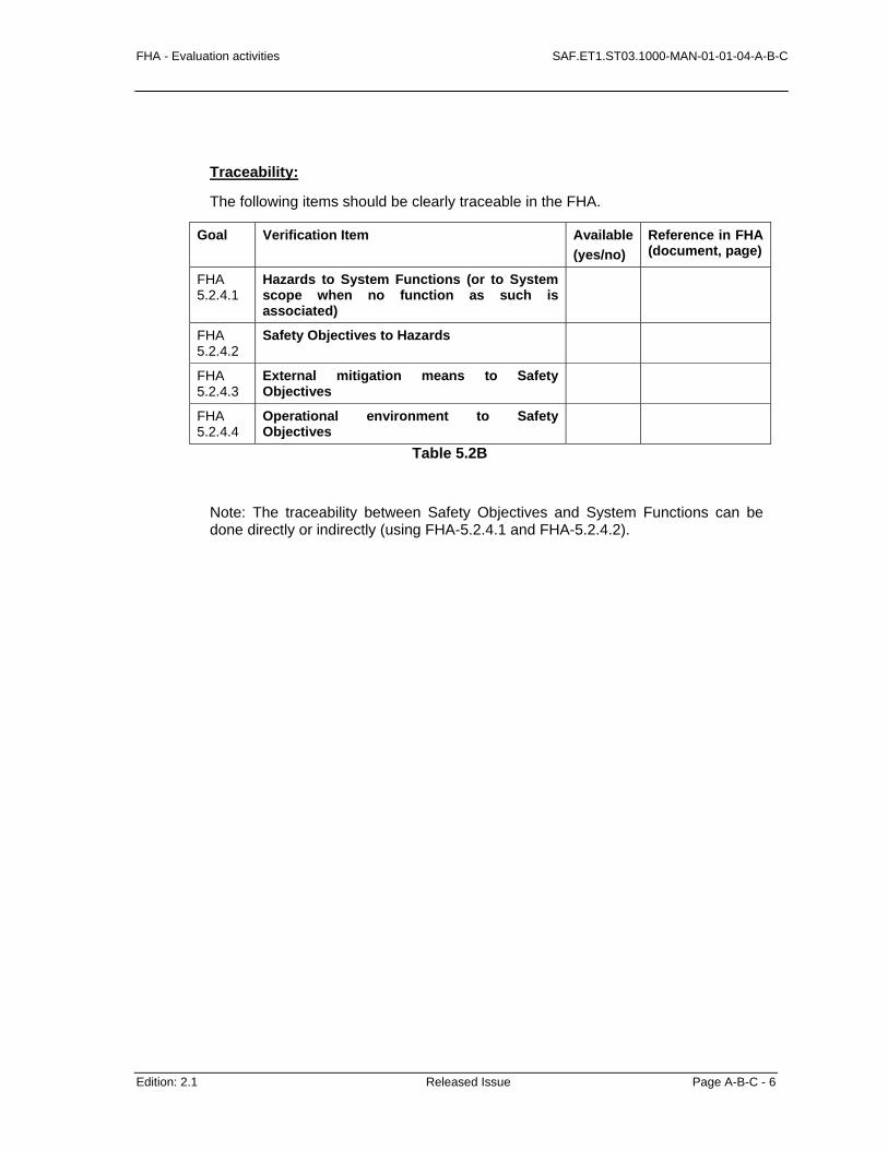
FHA - Evaluation activities SAF.ET1.ST03.1000-MAN-01-01-04-A-B-C
Edition: 2.1 Released Issue Page A-B-C - 6
Traceability:
The following items should be clearly traceable in the FHA.
Goal Verification Item Available (yes/no)
Reference in FHA (document, page)
FHA 5.2.4.1
Hazards to System Functions (or to System scope when no function as such is associated)
FHA 5.2.4.2
Safety Objectives to Hazards
FHA 5.2.4.3
External mitigation means to Safety Objectives
FHA 5.2.4.4
Operational environment to Safety Objectives
Table 5.2B
Note: The traceability between Safety Objectives and System Functions can be done directly or indirectly (using FHA-5.2.4.1 and FHA-5.2.4.2).

FHA - Evaluation activities SAF.ET1.ST03.1000-MAN-01-01-04-A-B-C
Edition: 2.1 Released Issue Page A-B-C - 7
6 FHA Validation
6.1 Objective
The FHA-SOS (Safety Objectives Specification) should demonstrate how Safety Objectives are derived.
The objective of validating the FHA is to ensure that the outputs of the FHA process are correct and complete. In other words this can be referred to as “getting the right output”, i.e. that the Safety Objectives are:
complete – this is assured through a review of the process used in the FHA;
correct - this is assured by reviewing the Safety Objectives themselves;
credible - the safety-related assumptions are appropriately justified and documented.
The validation goals are summarised in the figures below. The numbers refer to the location of guidance on each goal in the tables which follow.
Figure 2A: Output of FHA Process Validation goals

FHA - Evaluation activities SAF.ET1.ST03.1000-MAN-01-01-04-A-B-C
Edition: 2.1 Released Issue Page A-B-C - 8
Figure 2B: Hazard and Hazard Effects Validation goals

FHA - Evaluation activities SAF.ET1.ST03.1000-MAN-01-01-04-A-B-C
Edition: 2.1 Released Issue Page A-B-C - 9
Figure 2C: Safety Objectives Validation goals
6.2 Validation Process
Before conducting this task you will first need to make sure of the following:
That the verification of the FHA is complete.
That you have a description of the high level functions of the system.
That the Risk Classification Scheme is defined.
That the hazard identification is documented.
That the Safety Objectives have been documented.
The following tables list the validation items to be assessed for completeness and correctness. The validation goals are labelled according to Figures 2A, 2B & 2C above. The reviewer should signify by ticking the appropriate box whether the result is satisfactory i.e. conforming to the SAM methodology. The relevant FHA material should be referenced and qualifying comments made in the space provided, and amplified in the report as necessary.

FHA - Evaluation activities SAF.ET1.ST03.1000-MAN-01-01-04-A-B-C
Edition: 2.1 Released Issue Page A-B-C - 10
6.3 The system description
The Reviewer shall confirm the following:
Goal Validation Item: Validation Result
FHA 6.3.1
The system description provides sufficient detail to enable the reviewer to understand the functions of the system and how they interact internally and externally. The first thing to confirm is that the system description itself is complete and correct. Refer to SAM Part 1, Chapter 1 - FHA Initiation and GM A– Operational Environment Definition which lists items to be considered. Most importantly, confirm that the role and functions of the system and its interactions are described. The functions of interest are the safety-related functions necessary for the planned operation. To further aid in understanding the system a configuration diagram showing the main functional elements should be included.
Satisfactory Requires Action
Comment / action: Reference in FHA
FHA 6.3.2
The scope of the FHA matches the scope of the new system or change to the existing system correctly and completely. Review the description of the operational environment to confirm its completeness and correctness. The operational requirement and environment description is a useful tool for confirmation (assuming one is documented) otherwise make enquires to the relevant stakeholders.
Satisfactory Requires Action
Comment / action: Reference in FHA
FHA 6.3.3
Any new functions or interfaces identified in the FHA are valid. Note that the FHA may develop new functions and interfaces as a result of the definition process and these should be coordinated with the project manager.
Satisfactory Requires Action
Comment / action: Reference in FHA
Table 6.3
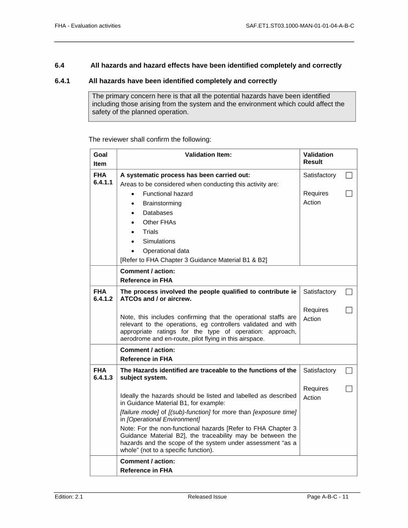
FHA - Evaluation activities SAF.ET1.ST03.1000-MAN-01-01-04-A-B-C
Edition: 2.1 Released Issue Page A-B-C - 11
6.4 All hazards and hazard effects have been identified completely and correctly
6.4.1 All hazards have been identified completely and correctly
The primary concern here is that all the potential hazards have been identified including those arising from the system and the environment which could affect the safety of the planned operation.
The reviewer shall confirm the following:
Goal Item
Validation Item: Validation Result
FHA 6.4.1.1
A systematic process has been carried out: Areas to be considered when conducting this activity are:
• Functional hazard • Brainstorming • Databases • Other FHAs • Trials • Simulations • Operational data
[Refer to FHA Chapter 3 Guidance Material B1 & B2]
Satisfactory Requires Action
Comment / action: Reference in FHA
FHA 6.4.1.2
The process involved the people qualified to contribute ie ATCOs and / or aircrew. Note, this includes confirming that the operational staffs are relevant to the operations, eg controllers validated and with appropriate ratings for the type of operation: approach, aerodrome and en-route, pilot flying in this airspace.
Satisfactory Requires Action
Comment / action: Reference in FHA
FHA 6.4.1.3
The Hazards identified are traceable to the functions of the subject system. Ideally the hazards should be listed and labelled as described in Guidance Material B1, for example: [failure mode] of [(sub)-function] for more than [exposure time] in [Operational Environment] Note: For the non-functional hazards [Refer to FHA Chapter 3 Guidance Material B2], the traceability may be between the hazards and the scope of the system under assessment “as a whole” (not to a specific function).
Satisfactory Requires Action
Comment / action: Reference in FHA
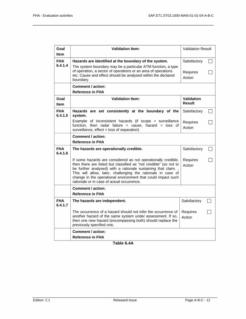
FHA - Evaluation activities SAF.ET1.ST03.1000-MAN-01-01-04-A-B-C
Edition: 2.1 Released Issue Page A-B-C - 12
Goal Item
Validation Item: Validation Result
FHA 6.4.1.4
Hazards are identified at the boundary of the system. The system boundary may be a particular ATM function, a type of operation, a sector of operations or an area of operations etc. Cause and effect should be analysed within the declared boundary.
Satisfactory Requires Action
Comment / action: Reference in FHA
Goal Item
Validation Item: Validation Result
FHA 6.4.1.5
Hazards are set consistently at the boundary of the system. Example of inconsistent hazards (if scope = surveillance function, then radar failure = cause, hazard = loss of surveillance, effect = loss of separation)
Satisfactory Requires Action
Comment / action: Reference in FHA
FHA 6.4.1.6
The hazards are operationally credible. If some hazards are considered as not operationally credible, then there are listed but classified as “not credible” (so not to be further analysed) with a rationale sustaining that claim. , This will allow, later, challenging the rationale in case of change in the operational environment that could impact such rationale or in case of actual occurrence.
Satisfactory Requires Action
Comment / action: Reference in FHA
FHA 6.4.1.7
The hazards are independent. The occurrence of a hazard should not infer the occurrence of another hazard of the same system under assessment. If so, then one new hazard (encompassing both) should replace the previously specified one.
Satisfactory Requires Action
Comment / action: Reference in FHA
Table 6.4A
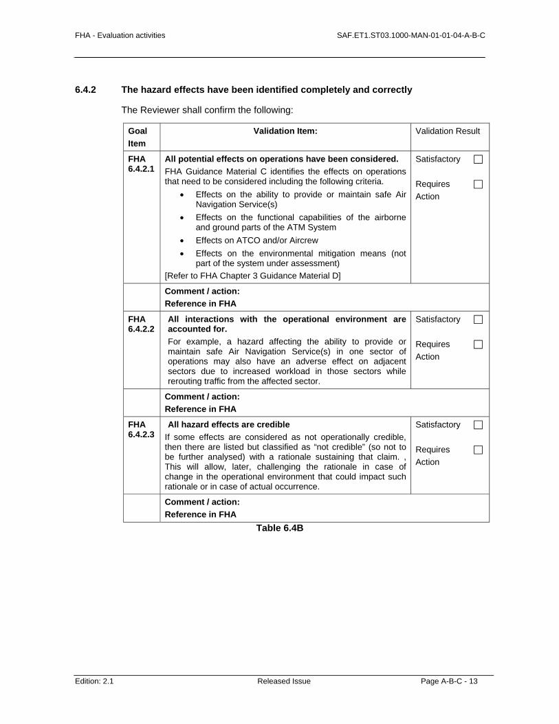
FHA - Evaluation activities SAF.ET1.ST03.1000-MAN-01-01-04-A-B-C
Edition: 2.1 Released Issue Page A-B-C - 13
6.4.2 The hazard effects have been identified completely and correctly
The Reviewer shall confirm the following:
Goal Item
Validation Item: Validation Result
FHA 6.4.2.1
All potential effects on operations have been considered. FHA Guidance Material C identifies the effects on operations that need to be considered including the following criteria.
• Effects on the ability to provide or maintain safe Air Navigation Service(s)
• Effects on the functional capabilities of the airborne and ground parts of the ATM System
• Effects on ATCO and/or Aircrew • Effects on the environmental mitigation means (not
part of the system under assessment) [Refer to FHA Chapter 3 Guidance Material D]
Satisfactory Requires Action
Comment / action: Reference in FHA
FHA 6.4.2.2
All interactions with the operational environment are accounted for. For example, a hazard affecting the ability to provide or maintain safe Air Navigation Service(s) in one sector of operations may also have an adverse effect on adjacent sectors due to increased workload in those sectors while rerouting traffic from the affected sector.
Satisfactory Requires Action
Comment / action: Reference in FHA
FHA 6.4.2.3
All hazard effects are credible If some effects are considered as not operationally credible, then there are listed but classified as “not credible” (so not to be further analysed) with a rationale sustaining that claim. , This will allow, later, challenging the rationale in case of change in the operational environment that could impact such rationale or in case of actual occurrence.
Satisfactory Requires Action
Comment / action: Reference in FHA
Table 6.4B

FHA - Evaluation activities SAF.ET1.ST03.1000-MAN-01-01-04-A-B-C
Edition: 2.1 Released Issue Page A-B-C - 14
6.5 The Safety Objectives are complete and correct
The Reviewer shall confirm the following:
Goal Validation Item: Validation Result
FHA 6.5.1
The severity classification scheme is appropriate to the type of operations envisaged for the system under assessment.
[Refer to FHA Chapter 3 Guidance Material D]
Satisfactory Requires Action
Comment / action: Reference in FHA
FHA 6.5.2
The reviewer shall confirm that the severity of the effects of hazards have been assigned completely and correctly. The different effects of hazards are described in the Severity Classification Scheme Guidance Material D. Each class of hazard effect has a defined severity indicator which can be found in Table D-2. One or more sets of severity indicators may be used. There is some degree of overlap between them and the user should have chosen those which best suit their conceptual model of the system. Not all sets of indicators, or all indicators within a set, are necessarily relevant or meaningful for every assessment.
Satisfactory Requires Action
Comment / action: Reference in FHA
FHA 6.5.3
The rationale for the severity assignment is clearly stated. A clear and complete description of the effects (especially what ATCO and/or aircrew have to do or can not do anymore) should be provided such that any reviewer that did not take part to the assessment can objectively understand and support the severity assignment.
Satisfactory Requires Action
Comment / action: Reference in FHA

FHA - Evaluation activities SAF.ET1.ST03.1000-MAN-01-01-04-A-B-C
Edition: 2.1 Released Issue Page A-B-C - 15
Goal Item
Validation Item: Validation Result
FHA 6.5.4
The Safety Objectives state what is required. [See FHA Chapter 3 GM G §6]
Satisfactory Requires Action
Comment / action: Reference in FHA
FHA 6.5.5
The Safety Objective specifies the maximum acceptable frequency of occurrence of the hazard. e.g. A or many unit(s) (flight hour, operational hour, per sector, etc.) is(are) used to specify Safety Objectives. FHA Chapter 3 Guidance Material G explains the various methods of setting Safety Objectives. One approach (mainly for “Uncertain Starters” or “Willing Developers”) consists in focusing on the Worst Credible case (not the Worst Case). ‘Worst’ means the most unfavourable conditions – e.g. extremely high levels of traffic or extreme weather disruption. ‘Credible’ implies that it is not unreasonable to expect to experience this combination of extreme conditions within the operational lifetime of the system; so that such a scenario leading to such an effect has to be considered. This approach (Worst Credible case) is not the only one acceptable and anyhow is not the most accurate and complete one (See Method 2 of FHA Chapter 3 GM G).
Satisfactory Requires Action
Comment / action: Reference in FHA
FHA 6.5.6
The Risk Classification Scheme is complied with. The Risk Classification Scheme (RCS) defined by the Organisation should be used. A RCS sets the maximum acceptable rate of occurrence of hazard effect (Safety Target ST) for a corresponding severity class of the hazard effect. [Ref: FHA Chapter 3 Guidance Material E]. Safety Objectives should be derived from the Safety Targets set in the RCS. The combination of Safety Objectives and mitigation means (external to the system under assessment) should satisfy the Safety Target per severity class.
Satisfactory Requires Action
Comment / action: Reference in FHA

FHA - Evaluation activities SAF.ET1.ST03.1000-MAN-01-01-04-A-B-C
Edition: 2.1 Released Issue Page A-B-C - 16
FHA 6.5.7
Even or uneven distribution of risk amongst Safety Objectives is justified. If the hazards having the same Worst Credible Consequence are allocated an even part of the risk associated to such effect severity, then such assumption shall be justified.
Satisfactory Requires Action
Comment / action: Reference in FHA
FHA 6.5.8
The probability that the hazard generates an effect (Pe) is justified. A Pe different from 1 shall be justified and requirements set on the external mitigation means that contribute to set such Pe.
Satisfactory Requires Action
Comment / action: Reference in FHA
Table 6.5
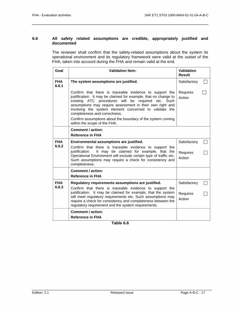
FHA - Evaluation activities SAF.ET1.ST03.1000-MAN-01-01-04-A-B-C
Edition: 2.1 Released Issue Page A-B-C - 17
6.6 All safety related assumptions are credible, appropriately justified and documented
The reviewer shall confirm that the safety-related assumptions about the system its operational environment and its regulatory framework were valid at the outset of the FHA, taken into account during the FHA and remain valid at the end.
Goal Validation Item: Validation Result
FHA 6.6.1
The system assumptions are justified. Confirm that there is traceable evidence to support the justification. It may be claimed for example, that no change to existing ATC procedures will be required etc. Such assumptions may require assessment in their own right and involving the system element concerned to validate the completeness and correctness. Confirm assumptions about the boundary of the system coming within the scope of the FHA.
Satisfactory Requires Action
Comment / action: Reference in FHA
FHA 6.6.2
Environmental assumptions are justified. Confirm that there is traceable evidence to support the justification. It may be claimed for example, that the Operational Environment will exclude certain type of traffic etc. Such assumptions may require a check for consistency and completeness.
Satisfactory Requires Action
Comment / action: Reference in FHA
FHA 6.6.3
Regulatory requirements assumptions are justified. Confirm that there is traceable evidence to support the justification. It may be claimed for example, that the system will meet regulatory requirements etc. Such assumptions may require a check for consistency and completeness between the regulatory requirement and the system requirements.
Satisfactory Requires Action
Comment / action: Reference in FHA
Table 6.6
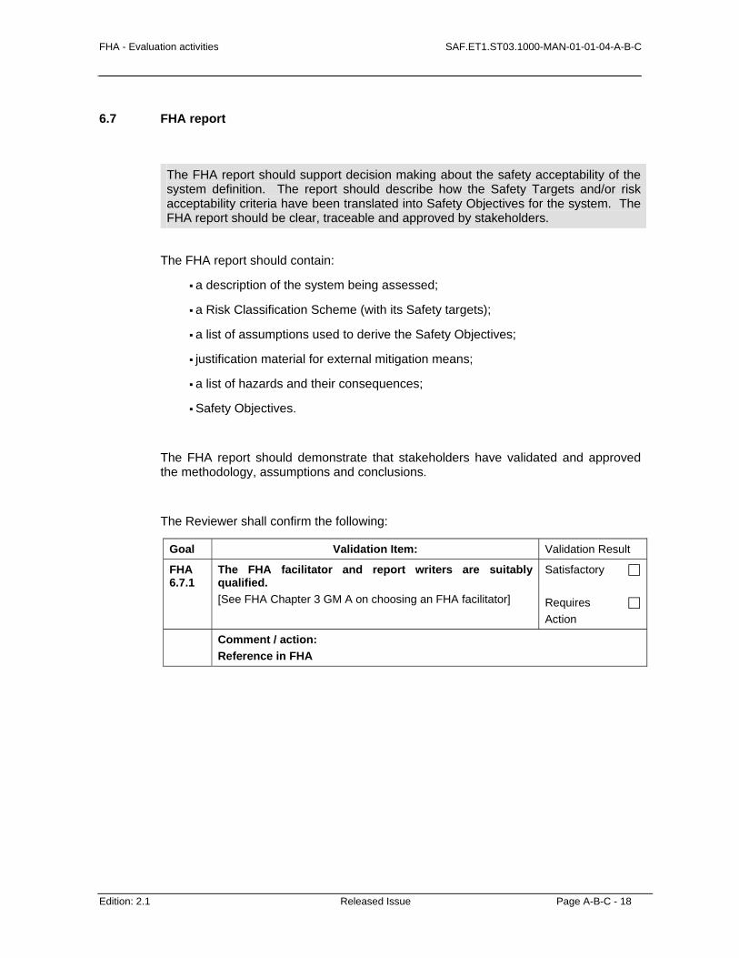
FHA - Evaluation activities SAF.ET1.ST03.1000-MAN-01-01-04-A-B-C
Edition: 2.1 Released Issue Page A-B-C - 18
6.7 FHA report
The FHA report should support decision making about the safety acceptability of the system definition. The report should describe how the Safety Targets and/or risk acceptability criteria have been translated into Safety Objectives for the system. The FHA report should be clear, traceable and approved by stakeholders.
The FHA report should contain:
a description of the system being assessed;
a Risk Classification Scheme (with its Safety targets);
a list of assumptions used to derive the Safety Objectives;
justification material for external mitigation means;
a list of hazards and their consequences;
Safety Objectives.
The FHA report should demonstrate that stakeholders have validated and approved the methodology, assumptions and conclusions.
The Reviewer shall confirm the following:
Goal Validation Item: Validation Result
FHA 6.7.1
The FHA facilitator and report writers are suitably qualified. [See FHA Chapter 3 GM A on choosing an FHA facilitator]
Satisfactory Requires Action
Comment / action: Reference in FHA
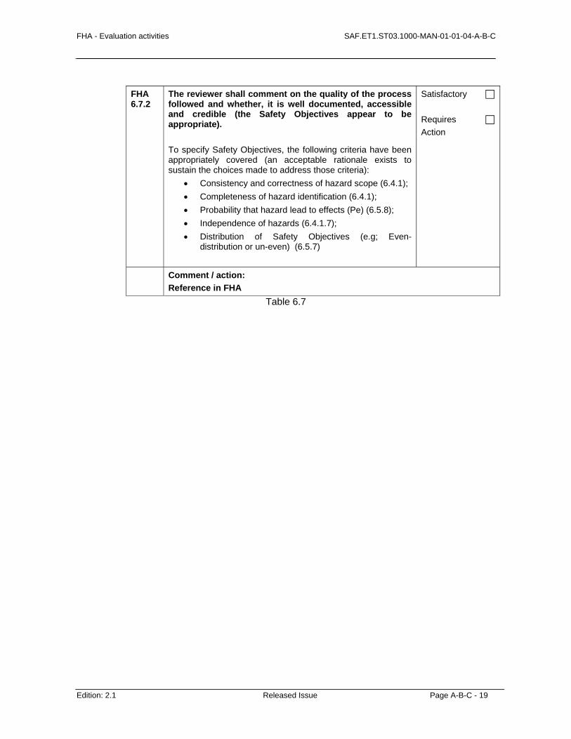
FHA - Evaluation activities SAF.ET1.ST03.1000-MAN-01-01-04-A-B-C
Edition: 2.1 Released Issue Page A-B-C - 19
FHA 6.7.2
The reviewer shall comment on the quality of the process followed and whether, it is well documented, accessible and credible (the Safety Objectives appear to be appropriate). To specify Safety Objectives, the following criteria have been appropriately covered (an acceptable rationale exists to sustain the choices made to address those criteria):
• Consistency and correctness of hazard scope (6.4.1); • Completeness of hazard identification (6.4.1); • Probability that hazard lead to effects (Pe) (6.5.8); • Independence of hazards (6.4.1.7); • Distribution of Safety Objectives (e.g; Even-
distribution or un-even) (6.5.7)
Satisfactory Requires Action
Comment / action: Reference in FHA
Table 6.7

FHA – Report SAF.ET1.ST03.1000-MAN-01-01-05-A
Edition: 2.1 Released Issue Page A-1
A
CHAPTER 5 GUIDANCE MATERIAL:
FHA REPORT
The FHA documentation records the results of the FHA assessment process. This document will be updated through the complete system life cycle.
In order to make this document readable and conveying efficiently key messages and results of FHA, recommendations are:
To keep the body of the document short (around 15 pages);
To make this document conclusive: clearly and concisely list the main findings of the FHA such as main Safety Objectives and assumptions;

SAF.ET1.ST03.1000-MAN-01-01-05-A FHA – Report
Page A-2 Released Issue Edition: 2.1
To include an executive summary;
To contain the results of detailed analyses in annexes.
A possible structure for the FHA report is provided below.
Executive Summary
It should focus on main messages delivered by FHA, such as: what are the main hazards, Safety Objectives and assumptions, recommendations and conclusions.
Introduction
This section describes:
• The objectives of the document.
• The scope of the FHA (What was addressed in the FHA process and what was not addressed).
• The structure of the document.
System Description
This section provides an overview of the system purpose and functions in order to provide an understanding of the safety issues raised.
It will cover, or reference, documentation describing:
• The purpose and boundaries of the system;
• The system operational environment (if appropriate, the assumptions made about this operational environment);
• The operational scenarios;
• System functions and their relationships;
• The external interfaces.
It will also identify whether the system is new, a replacement or a modification of an existing system.
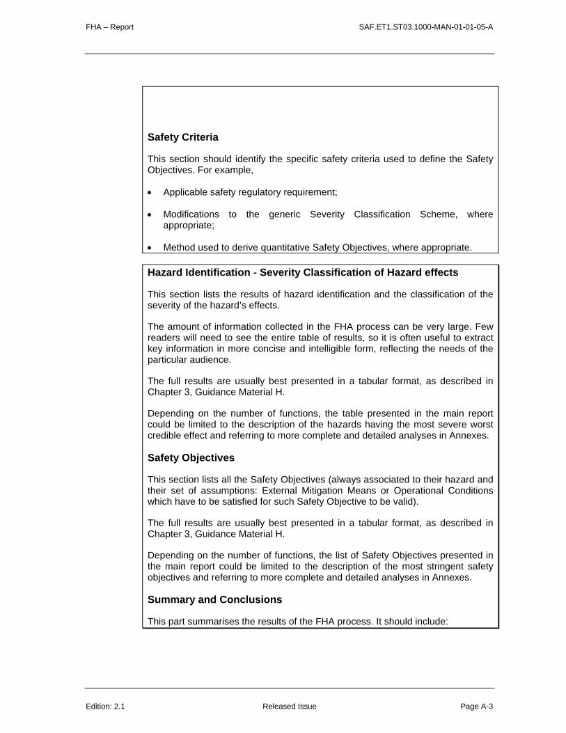
FHA – Report SAF.ET1.ST03.1000-MAN-01-01-05-A
Edition: 2.1 Released Issue Page A-3
Safety Criteria
This section should identify the specific safety criteria used to define the Safety Objectives. For example,
• Applicable safety regulatory requirement;
• Modifications to the generic Severity Classification Scheme, where appropriate;
• Method used to derive quantitative Safety Objectives, where appropriate.
Hazard Identification - Severity Classification of Hazard effects
This section lists the results of hazard identification and the classification of the severity of the hazard’s effects.
The amount of information collected in the FHA process can be very large. Few readers will need to see the entire table of results, so it is often useful to extract key information in more concise and intelligible form, reflecting the needs of the particular audience.
The full results are usually best presented in a tabular format, as described in Chapter 3, Guidance Material H.
Depending on the number of functions, the table presented in the main report could be limited to the description of the hazards having the most severe worst credible effect and referring to more complete and detailed analyses in Annexes.
Safety Objectives
This section lists all the Safety Objectives (always associated to their hazard and their set of assumptions: External Mitigation Means or Operational Conditions which have to be satisfied for such Safety Objective to be valid).
The full results are usually best presented in a tabular format, as described in Chapter 3, Guidance Material H.
Depending on the number of functions, the list of Safety Objectives presented in the main report could be limited to the description of the most stringent safety objectives and referring to more complete and detailed analyses in Annexes.
Summary and Conclusions
This part summarises the results of the FHA process. It should include:

SAF.ET1.ST03.1000-MAN-01-01-05-A FHA – Report
Page A-4 Released Issue Edition: 2.1
• The list of major hazards and their effects, i.e., those with highest severity classifications;
• The list of quantitative and/or qualitative Safety Objectives;
• The assumptions (External Mitigation Means, Operational Conditions) to be satisfied per Safety Objective;
• The main conclusions of the FHA Verification, FHA Validation and FHA Process Assurance activities;
This part also identifies any hazards requiring additional analysis, and/or other priorities for further attention in the development/ assessment cycle.
Annexes
• Detailed result tables
• Cross references to other documents produced within the FHA process, such as the FHA Plan (as described in Chapter 2) and the results of the FHA Verification, FHA Validation and FHA Process Assurance tasks (as described in SAM-FHA Chapter 4).
• References to external documents – e.g. regulatory requirements, documentation for systems interacting with the proposed system.
• Traceability Matrices:
• Traceability matrices:
Hazards <> System Functions Safety Objectives <> Hazards External Mitigation Means <> Safety Objectives Operational Environment <> Safety Objectives