Embed Size (px)
Citation preview

Rochester Institute of Technology Rochester Institute of Technology
RIT Scholar Works RIT Scholar Works
Theses
5-1-1972
Salt Glazed Clay Surfaces Salt Glazed Clay Surfaces
Brian Williams
Follow this and additional works at: https://scholarworks.rit.edu/theses
Recommended Citation Recommended Citation Williams, Brian, "Salt Glazed Clay Surfaces" (1972). Thesis. Rochester Institute of Technology. Accessed from
This Thesis is brought to you for free and open access by RIT Scholar Works. It has been accepted for inclusion in Theses by an authorized administrator of RIT Scholar Works. For more information, please contact [email protected].

oALT GLAZED CLAY SURFACES
BY
BRIAN WILLIAMS
Candidate for the Master of Fine Arts
in the College of Fine and Applied Arts
of the Rochester Institute of Technology
Advisors: Hobart Cowles
Robert Schmitz
Date of Submission: May, 1972

11
The topic of my thesis work is Salt Glazed
Clay Surfaces. I had no idea at the outset that
the study of this area of ceramics, for me, would
be such an involved experience. In addition to an
exploration of possible surface embellishments ap
propriate to salt glazed ware, much study was
given to kiln construction and firing techniques,
use of coloring agents, and clay body formulation.
Because of the many inconsistencies from one firing
to the next, it is difficult, if not impossible,
to duplicate specific results or to previsualize
certain effects in finished pieces. For this same
reason, it is almost as difficult to come to ab
solute conclusions about the methods tested or the
techniques employed. Accordingly, much of my re
search was conducted with the intent being to
understand salt glazing and not to ultimately con
trol it.
My hope is that this paper will, in addition
to being a report of my thesis work, save other
potters the time and expense of trial and error ex
perimentation and poor choices of materials.

Ill
TABLE OF CONTENTS
Page
I. List of Tables iv
II. List of Illustrations v
III. Thesis Report
Introduction 1
Kiln Design and Construction 3
Firing and Salting Procedures ..... 16
Clays and Olay Body Formulation .... 19
Coloring Oxides and Slips 31
The Salt Glazed Surface 33
Conclusion 50
IV- Appendix
Appendix A 51
Appendix B 52
Appendix C 56
V. Bibliography 60

iv
LIST OF TABLES
Page
Table 1 21
Table 2 22

LIST OF ILLUSTRATIONS
Page
Figure 1 10
Figure 2 11
Figure 3 H
Figure 4 . 12
Figure 5 12
Figure 6 13
Figure 7 13
Figure 8 14
Figure 9 15
Figure 10 39
Figure 11a 40
Figure lib 40
Figure 12 41
Figure 13 42
Figure 14 43
Figure 15 44
Figure 16 45

vi
LIST OF ILLUSTRATIONS, cont.
Page
Figure 17 46
Figure 18 47
Figure 19*
47
Figure 20 48
Figure 21 48
Figure 22 49
Figure 23 49

INTRODUCTION
Salt glazing of ceramic ware is not a new process-
Its use dates back to 12th century Germany. In
America, salt glazing predominated as the usual method
employed by most stoneware potters until the l88Q's
when the Bristol glaze was introduced. Within the
past few years, however, salt glazing has enjoyed
renewed popularity as a technique employed by many
potters.
Salt glazed ware is economical to produce. The
pieces need only be once fired and are rendered water
proof without the use of applied glazes. Industry
has made much use of the technique in the production
of chemical stoneware and building materials such as
tiles, bricks and conduits. Sewer pipes are a good
example of a salt glazed product which is durable,
waterproof, and resistant to chemical attack.
The method of salt glazing is a simple process.
the ware is heated to a temperature where vitrification
of the clay begins, at which point salt (sodium cloride)
An exception to this would be closed forms and
covered jars which are usually lined with a slip or
glaze due to the salt having no effect on enclosed
surfaces.

is introduced into the kiln. The salt volatilizes
forming fumes of sodium oxide which combine with the
free silica in the clay forming a sodium silicate.
This in turn combinea with the clay substance, thus
forming a sodium aluminum silicate glaze on the sur
face of the ware. The by-product of this process is
chlorine gas which combines with hydrogen to form
hydrochloric acid. In addition to forming a g3-aze
on the ceramic ware, the sodium fumes also attack the
shelves, kiln furniture, and the inner kiln wall.
Thia necessitates a kiln especially suited to salt
glazing.
The salt glaze is quite unique, usually having
a glossy surface interrupted, to varying degrees,
by numerous small pits or craters. The resulting
glaze texture resembles the "pigskin"
of a football
or the surface of an "orangepeel."

KILN DESIGN AND CONSTRUCTION
Before ajiy salt glazing could be initiated at
R.I.I. , a kiln dedicated to this process had to be
constructed. Soft insulation brick: could not be used
since the corrosive sodium vapors would disintegrate
the lining in the first firing. A hard fire brick
lining is much more resistant to the^ sodium vapors
and is, therefore, a necessary choice. With successive
firinga, however, the hard brick will season (take
on a salt glaze) and eventually disintegrate where
upon the kiln will, in effect, self-destruct. With
proper materials and construction techniques, a salt
kiln should last in excess of 100 firings.
The most common kiln design used for small (100
cubic feet or less) salt kilns is a down draft style.
This design insures more complete circulation of the
sodium fumes throughout all parta of the kiln.
I1l was decided to construct the kiln from materials
already on hand. A catenary arch design was chosen
since most of the available hard brieks were of the
wedge and arch variety. A castable refractory made
from crushed insulation bricks with Portland cement
and fireclay as a binder would serve as a secondoz*
insulating layer, and a weather proofing shell could
be constructed from the seemingly endless number of
common bricks leftover from the construction of the
new campus.
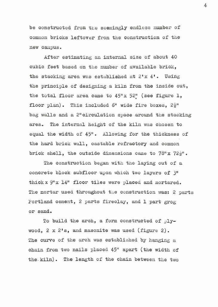
After estimating an internal size of about 40
cubic feet based on the number of available brick,
the stacking area was established at 2'x 4'. Using
the principle of designing a kiln from the inside out,
the total floor area came to 45"x
52^* (see figure 1,
floor plan) . This included 6"wide fire boxes,
2-g-"
bag walls and a2"circulation space around the stacking
area. The internal height of the kiln was chosen to
equal the width of45"
Allowing for the thickness of
the hard brick wall, castable refractory and common
brick shell, the outside dimensions came to 78"x72i-".
The construction began with the laying out of a
concrete block subfloor upon which two layers of3"
thick x 9"x14" floor tiles were placed and mortared.
The mortar used throughout tne construction was: 2 parts
Portland cement, 2 parts fireclay, and 1 part grog
or sand.
To build the arch, a form constructed of ply
wood, 2 x 2's, and masonite was used (figure 2).
The curve of the arch was established by hanging a
chain from two nails placed45"
apart (the width of
the. kiln) . The length of the chain between the two

nails was adjusted until the bottom of the curve it
defined fell 45" (the height) below the line drawn
between the two nails. The curve of the chain was
then traced onto two plywood sheets which were cut
out to become the end walls of the arch form. The
completed form was placed on the kiln floor and con
struction of the arch began, first using the wedge
bricks until their supply was exhausted and then re
sorting to arch bricks to complete the job (figure j) .
ojjace for two burner portsAP'
x4"a"
was allowed at
the base of each side of the arch. The back wJI
v/as then built up underneath the arch thus giving
it added support and serving as a partial heat lock.
An8-g-"
x8a"1*
opening was allowed in the bottom of
the back wall for the flue.
An insulating layer of a castable refractory
was now applied over the entire hard brick lining.
The recipe for the castablt used is 1 part cement,
1 part fireclay, 2 parts crushed insulation brick
and 1 part sawdust or woodchips. oinoe the cast-
able had a tendency to sag before it set, especial
ly on the vertical sections, tne outer common brick
shell was constructed at tne same time the castable
was applied, that is, a foot of castable, a foot
of common brick, a foot of castable, and so on.
(See figure 5.) As an additional insulation, as-

bestos planks were used on the crown of the kiln be
tween the castable and the common brick outer shell.
(See figure 7.) The asbestos being soft and some
what spongy, would also serve to absorb the expansion
of the inner layers of the kiln which would occur
during firing. This would hopefully eliminate ex
tensive cracking of the outer shell.
The two front wall sections were now built thus
completing the major construction of the basic kiln.
Two "saltingports"
v/ere left in the wall sections,
one on each side of the door opening, each being
located at about20"
above the kiln floor.
The stack, standing about15'
hi^h with a cross
section of18"
x 18", was constructed of common brick.
The unusually large dimensions of the stack are ex
plained by the fact that ultimately three kilns would
be tied into it, possibly all firing simultaneously.
A horizontal flue connecting the kiln to the stack
was built out of hard fire brick leaving a slot wide
enough for the damper (an old kiln shelf was used)
about midway in its length.
The door to the kiln is simply an unmortared
wall of bricks: three bricks wide (27") and two bricks
thick (9"
) . The door is made of hard fire brick on
its inner layer and insulation brick on its outer

face. Lastly the bag walls were laid in place thus
defining the fire boxes. (See figure 1, front cross
section.)
A protective wash of 65$ alumina oxide and 35$
kaolin was applied to the floor, bag walls and fire
boxes to prolong the life of these areas most subjec
ted to the sodium fumes. The inner surface of the
door was also washed so as to keep the bricks from
being glazed together.
Four forced air burners from an old Alpine up
draft were modified for use on the salt kiln. The
original blowers did not deliver sufficient air to
produce an oxidation flame and were therefore even
tually replaced with a system of air pipes connecting
the burners to a large Denver Fireclay blower (figure 8).
With this air system it was quite easy to maintain an
oxidation atmosphere in the kiln yet reduction could
be produced by simply cutting back: on the air supply
from the blower. The firing and salting procedures
will be discussed later.
It is important to mention, at this point, the
effect of a number of firings, on the kiln materials
used. Three types of hard brick were used, A. P. Green
Valentine XX bricks, Harbison-Walker Temple bricks, and
Harbison-Walker Woodland X bricks. The Valentine XX

8
and Temple bricks were given to the school by the
Syracuse China Corporation. The Temple bricks,
appearing to be less porous and harder than the
Valentine XX bricks, v/ere used around the burner
ports and in the bag walls. The Valentine XX bricks
made up all of the arch except for two rows of
Woodland X bricks.
After the first few firings the .Temple bricks
showed much deterioration in the form of sagging,
foaming and breaking apart. The Valentine XX bricks
held their shape rather well, but were very heavily
glazed and showed separation betv/een the joints.
This is partly explained, in that the mortar melted
and ran out from between the bricks. A call to the
local brick representative provided the explanation
for this rapid deterioration. The Temple bricks
are the lowest duty variety in the Harbison-Walker
product line and were not designed to withstand the
temperatures and atmosphere found in the salt kiln.
The Valentine XX is a"semi-silica"
brick which is
produced for use in blast furnaces and open hearths..
The high silica content gives the brick a substantial
refractory quality, but at the same time makes for
heavy glazing and deterioration of the exposed surface
in the salt kiln. The Woodland X bricks have held up

very well to this point (ten firings). They have
maintained their original-shape and show minimal
glaze build up.
As a hindsight consideration of the selection
of materials, I would suggest using a high duty or
super duty brick throughout the kiln cemented together
with a high alumina mortar. The salt kilns at
Alfred University are constructed with Harbison-
walker Woodland X bricks. Don Reitz. uses A. P. Green
Clipper bricks and recomends A. P. Green Satanite or
Grefco's Arco 70 as mortars. At an additional expense
high alumina bricks could also be used, especially
in the fire boxes and around the burner porta.
Appendix A contains a listing of fire bricks
tested in the salt kiln for their resistance to
salt glazing

10
6^-6Ey/7767/6^6Fi6v:/jAE4AP4E rp
:ZR.'rz likOCX
Fp.OfJT CPoss Sezriou
SSN.W>'
.w^v n>nv^v< ;^\\
,i : 4 Z4,r4EP4mEiA,4;m4^M
4 .4 .
mppf666E6^^mM66mi
i
fc^/fy, *U
/&*'
r
ra
W&m&m%% fr
{&AO Wax u O^irrcj))
i,44^.
44:^E
EPp6
':/.
Hr1'
^-..L_4ii4E/V
inm6i6p666p6
-666E6E666
FF-///'
/ 446- "4
Frr
/-lyZ'y//'
/yy
E
'pmFEEEEEz.76"
f^OOli P<-A'J
Scale:t"
=Z7"
E\ La^taqi-E /?/:/.c;or6'/?/
Figure 1. Salt kiln plan.

-*.r
Figure 2. Kiln floor v/ith arch form.
;^S3^-
&*#
Ik -Hi
figure 3 Hard oric3c arch and burner
ports.- Note the use of wedge and arch
bricks.

gmFigure 4. hard brick arch
with form removed.
r
W!!
1
Figure 5. Detail of cast-
able refractory and shell
construction.
*
f\

m**JL*'ji
i
at
jfll
M mam1
-
, y>
1 i
P*
*^^ I'm
=.
8Figure 6. nard brick arch with cast-
able refractory cap. Bricks tempor
arily stacked for door.
J? -
J ..
i.^?^J**^ Jr
l l
A
' ^
1
~
if
is
/<: 4 . '..
H
AT-V-"
-
ffl i
~'~v-_ ..
y-
~^^^^z, -^".JWlV.I
-..,4
"* 1
.
rr.1
MMP3*
Figure 7. Letail of as
bestos planks between
castable refractory and
common brick shell.

CO
M
o
d
xi
o
o
r4H
CO
CD
cD

15
HH
3ra
p
H
o
<D
EH
CTi

16
FIRING AND SALTING PROCEDURES
An oxidizing atmosphere is maintained in the kiln
fron the beginning of the firing cycle until cone 9 is-
flat. During this time the damper ia kept wide open.
At cone 9, the damper is closed until there is back
pressure producing a flame of about6"
at, the front
spy holes and salting ports. This is done to insure
a thorough saturation of the atmosphere with sodium
vapors. In addition, the reduction and fire flash
ing that occurs when the damper is closed converts
the ferric iron to the ferrous state in which con
dition the clay will take a better glaze. At. this
point the salt is introduced into the kiln, prefer
ably in small quantities. I use about ten pounds
per salting. One of the salting techniques I have
used is to toss scoops full of salt in front of the
burners through the burner ports. This system works
relatively well as long as you have a good aim and
do not spill too much salt,. Another salting method
is to fill a long section of angle iron with salt,
insert in through one of the front salting ports
and rotate it in the direction of the fire box so
that the salt falls into the flames. This system is
very efficient in that there is little spillage or

17
loss of salt, but it requires two people to complete
the salting, one to hold the angle iron and the
other to fill it with salt.
Periodically, during each salting, the damper
is rapidly pushed in and pulled out a number of
times to pull the atmosphere, in jerking movements,
to all parts of the kiln. This also insures that
the sides of the pieces facing away fsom the fire
boxes are well glazed. At the end of the salting, the
damper is opened and the kiln atmosphere is allowed
to clear (usually about five minutes) . One of the
draw rings which have been placed near a spy hole
in the door is pulled to examine the glaze buildup
after each salting. The ring should have a broad
enough surface to adequatly show the glaze buildup
and it should be made of the same clay as is used in
the majority of the pieces in the kiln, a small
ring shape is usually chosen so that it can easily
be hooked with a rod and pulled out through the spy
hole. The color of the ring is not a good indication
of the color of the finished ware. The extremely
quick cool, usually quenching it in water, gives the
ring a very light color.
The saltings continue until the ^laze on the
draw rings is of the desired thickness. After the

18
last salting, the firing is allowed to continue for
another fifteen minutes or so to allow the kiln
atmosphere to clear as much as possible. The burners
are turned off, the damper is closed and the burner
ports are bricked up to prevent cold air from being
drawn into the kiln, possibly causing dunting and
mat'
surfaces on the pieces near the fire boxea. .
I find that a rapid cool of the kiln produces brighter
colors, particularly in slip decorated ware, a shinier
surface, and a more pronounced orange peel effect.
The fast cool also keeps the clay from turning brown
which would occur through the reoxidation of the iron
on the surface from the ferrous to the ferric state.
The rapid cool is accomplished by removing the top
few courses of brick from the door which allows the
heat to escape in updraft fashion. Just prior to the
loss of red heat, the kiln door is bricked up again
to slow the cooling through the quartz inversion
temperatures .

19
CLAYo AND CLAY BODY FORMULATION
There are three main factors that effect the amoun:t
of salt glaze that will form on a clay: the amount of
salt introduced into the kiln, the amount of free silica
present in the clay, and the degree of vitrification of
the clay at the time of salting.
Throughout all of my firings, I have tried to
keep the glaze thickness, due to the amount of salt
used, constant. Less salt needed to be Ubed with each
successive firing because of increasedseasoning-^
of
the kiln. Even with this attempted control, certain
areas of the kiln would produce more heavily glazed
pieces than others. This may be due to a heavier
concentration of sodium vapors in these areas.
Free silica is necessary in. a clay for the formation
of a salt glaze. Clays do not occur naturally in the
form of oxides, as might be concluded from studying a
chemical analysis, but are made up of various mineral
constituants including clay substance or kaolinite
(A12Q. 2Si20j, feldspar (XNaOA1203 6Si02), and
quartz, or free silica (SiO^). Free silica is, therefore,.
-*With each firing, the glaze buildup on the kilnwall increases and therefore absorbs less of the sodium
vapors. Ihe effectiveness of the salt is increasedwith each firing, therefore less is needed.

20
that silica which occurs in a clay in excess of the
combined silica of the clay substance and of the
feldspar. The amount of free silica, in any given
clay can be determined from its chemical analysis
by various methods, including a conversion to "ra
tional analysis" which expresses the clay in terms
of its mineral components.
Another and much simpler way of relating the
silica content of a clay to its ability to take a
salt glaze is by determining the ratio of its alumina
molecules to its silica molecules (Al20Vsi02) . From
its chemical analysis, this is easily done by dividing
the alumina content into the silica content and redu-
ing the results to a molecular ratio. An example
follows for E.P.E. The alumina and silica content is
taken from Table 1.
(a) 45.91 (fi Si09) 1.185_ = 0r 1:1.185
38.71 (/o A1203) 1
(b) Reduce to molecular ratio.
1 4 102 (Mol.Wt. of A1203) : 1.185 -r 60 (Mol.Wt. of SiOj
.0098: .0197
1: 2 (Al203/Si02 of E.P.K. )
A simple equation quickly renders the same results.
Al203/Si02= 1: (fi Si02
4- fi A1203) x 1.7

21
Therefore E.P.K.'s Al203/Si02 could be calculated
as follows:
Al203/Si02 (E.P.K.) = 1: (45-91 -r 38.71) x 1.7
1: 1.185 x 1.7
1: 2
The following tables show the chemical analyses
and the Al203/Si02 of the clays tested.
Clay
E.P.K.
TABLE 1
CHEMICAL ANALYSIS OF CLAYS TESTED
Si02 A12(X Fe20v KNaO TiO CaO MgO L.O.I,
45.9 38.71 .4-2 .26 .34 .09 .12 14.15
A.P.G. Mo.
Fire Clay
Term. #5Ball Clay
Ky. Special
Ball Clay
XX Sagger
56.5 38.5 1.8 1.0 1.5 .5
51.79 31.31 1.01 2.31 1.41 .26 .20 11.70
49.64 29.33 .95 1.25 1.48 .29 .25 16.8
56.68 29.19 .72 1.20 1.65 .45 .32 9.9
CH. Goldart 57.32 28.50 1.23 1.18 1.98 .08 .22 9.39
Jordan 67.19 20.23 1.73 2.23 1.18 .16 .52 8.89

22
Clay
E.P.K.
TABLE 2
Al203/Si02 OF CLAYS TESTED
fi Si02 ^.A1203
45.91 38.71
Al203/Si02
1:2
A.P.G. Mo.
Fire Clay56.5 38.5 1:2.5
Tenn. #5Ball Clay
51.79 31.31 1:2.8
Ky SpecialBall Clay
49.64 29.33 1:2.9
XX Sagger 56.68 29.19 1:3.3
CH. Goldart 57 = 32 28.50 1:3.4
Jordan 67.19 20.23 1:5.6
All of the above clays were made into test bars
and fired in the salt kiln. To insure an adequate
sample for evaluation, a number of bars were made
from each clay and at least two were placed in each
of three different firings.
The results of the clay tests follows. The clays
are listed in order of increasing thickness of salt
glaze. Al203/Si02 of the clays are included.
E.P.K. -(1:2.0) Light in color with orange flashes on
most of the exposed surfaces. No glaze formation,

23
This is mostly due to no free silica present
in the clay.
A.P.G. Missouri Fire Clay-(l:2.5) Dark brown with a
rough texture, possibly due to the large partical
size of the clay. Thinly glazed surface with
much strong pitting.
Tennessee #5 Ball Clay-(1:2.8) The lightest color of
the ball clays tested. Light tan to cream color
with a finely textured surface.
Kentucky Special Ball Clay-(l:2.9) Warm tan to light
brown with a smoothly glaffied surface, smoothest
of all of the clays tested.
XX Sagger-(1: 3.3) Rich warm yellow color with orange
flashes. Delicate orange peel texture on a
fairly thick glaze.
Cedar Hights Goldart-(l: 3*4) Light brown to tan to
warm grey. Thick, textured glazed surface that
could be called the typical "orange peel"
effect.
Jordan-(l:5.6) Cool brown to light grey in color with a
fine orange peel texture. The thickest glaze of
all clays tested.

24
It is important to note the direct relationship
between the glaze thickness and the Al203/si02 of the
clays. E.P.K., with no glaze, has a ratio of 1:2
and Jordan, with the thickest glaze, has a ratio of
1:5.6.
Another factor which effects glaze build up on
a clay is its degree of vitrification at the time of
salting. At cone nine, E.P.K. is the least vitreous
of the clays tested, its absorption being 13fi.
Jordan's, absorption at cone nine is about 1.5$ making
it the most vitreous.
To confirm the above relationships, a series of
tests were developed. E.P.K. was chosen as one of the
base clays for the tests because it is not vitreous at
cone nine, has no free silica, and does not take a salt
glaze. The first series included additions of silica
to E.P.K. increasing its Al203/Si02 from 1:2 to 1:11.
A second series of tests with feldspar additions was
performed to study the effect of fluxing the clay.
A. third test series was made with additions of Plastic
Vitrox. Plastic Vitrox was chosen since, from its
empirical formula, it resembles a feldspar yet has
more than twice as much silica.
Theoretical Feldspar:
1R0^A1203 6Si02
Plastic Vitroxt
1R01.69A1203 14.67Si02

25
Similar additions were made to A.P.G. Missouri
Fire Clay (A.P.G. ), to observe the effect on the color
of the dark clay, and to a basic stoneware Test Body.
The test body was formulated to have good working
qualities, light color, and an ability to take an
"orange peel"
type salt glaze. Cedar Hights Goldart
was chosen for its general working characteristics
and orange peel glaze, A.P.G. to add tooth and to
open up the body, and Tennesee jf5 Ball Clay for its
light color and plasticity.
Test Body
CH. Goldart 50
A.P.G. 20
Tennesee #5 Ball 25
Grog 5
100
The tests were made into small bars and fired in the
salt kiln. To measure vitrification, duplicate tests
were fired in a regular stoneware kiln to cone10-11^
and their percentage of absorption was calculated.
The results of these absorption tests can be found in
^"These tests were intended to be fired to cone 9,but overfired. Regardless, the trends which can be seen
in the results of the tests are what is important.
26
Appendix B .
In every case, the additions of flint to the
clays improved their ability to take a glaze. The
E.P.K. series, with flint additions, dramatically
illustrates the effect of the increased silica on
the glaze and the color of the clay. With no flint
addition, the E.P.K. tile has a smooth but dry sur
face with no glaze formation. As flinjfc is added,
up to 20 parts to 100 parts of E.P.K., the orange
color of the exposed surfaces lightens to a creamy
tan, and some glaze formation is evident. With 25
parts flint, the Al20VSi02 is increased to 1:3.1,
the glaze buildup is good, and the tile is a creamy
white with only slight orange flashes. Increasing
additions of flint continue to whiten the clay and
improve the glaze thickness. At 200 parts flint to
100 parts E.P.K., the tile is a clean, bright white
color with a delicate orange peel type glaze.
The A.P.G. tests with flint additions produced
similar results to tne E.P.K. series. With increas
ing additions of flint to 100 parts of A.P.G-, the
Al20-,/Si02 is increased to 1:3.0 and a good glaze
formation occurs.
The Test Body, with an Al203/Si02 of 1:3.0 takes
a fairly good glaze which is improved with the addition

27
of flint, as in the above tests, the color gets
lighter with increased flint. In both the Test Body
and A.P.G. test series, the pitting or orange peel
effect becomes stronger with the flint additions
until the absorption of the test tiles exceeds Ifi.
At this point, the glaze surface begins to smooth
out and the pitting becomes delicate and less pro
nounced.
Custer Feldspar was chosen for the feldspar
additions to the test series. It has slightly more
silica than the theoretical feldspar.
Theoretical Feldspar:
1R0 *
A1203 6Si02Custer Feldspar:
lKNaO *
1.05A1Z03 7.05Si02
In each of the series, the feldspar additions
increase the vitrification of the clay and, like the
flint, lighten the color. The feldspar additions to
E.P.K. did little to affect its ability to take a
glaze. With the larger feldspar additions, a very
thin glaze forms which is probably due, in part, to
the introduction of some free silica with the feldspar,
A.P.G. shows an improvement in glaze thickness
with the initial feldspar additions. Additions in
excess of 20 parts per 100 parts of A.P.G. seem to
have no effect other than to lighten the color.

28
The Test Body is effected similarly by the feldspar.
The initial addition of 3 parts feldspar to the body
reduces the absorption by almost one half and produces
a marked improvement in the glaze thickness. Subsequent
additions of feldspar increase the vitrification only
slightly and the glaze thickness shows little improve
ment.
As a follow up to the above tests, combined additions
of feldspar and flint were made to the Test Body, with
2 parts flint and 2 parts feldspar added to 100 parts
of the Test Body, the color is much lighter and the
glaze thickness is greatly improved. This combined
addition produces a thicker glaze than either the flint
or feldspar added separately. Subsequent combined
additions continue to improve the glaze slightly.
In general, the Plastic Vitrox additions did not
produce results as satisfactory as those obtained by
using feldspar, flint, or the two in combination. As
a flux, Plastic Vitrox is not as effective, weight for
weight, as the feldspar in reducing absorption and as
a source of silica, Plastic Vitrox does not compare
to flint. A combined addition to the Test Body of 6
parts of flint and 6 parts of feldspar produces a
thicker glaze and a more vitreous clay body than does
an addition of 12 parts of elastic Vitrox.
29
Talc (3MgO 4Si02 H20) and Wollastonite (CaO Si02)
were tested for use as possible fluxes in salt bodies.
In both cases, when 10 part additions were made to the
test body, dry crystalline mat surfaces were produced.
Spodumene (Li2 A1203 45i02) , used in 10 percent
additions, produces a bright glazed surface that, is
subject to severe shivering.
Silica sand added to a clay body will increase
the orange peel character of the glaze. Whereas
finely ground (200 or 350 mesh) silica added to a clay
body increases the glass forming material and according
ly improves the glaze thickness, a concentration of
silica, like that found in the larger particle size of
silica sand, tends to repel the salt glaze. The orange
peel quality of tne salt glaze on naturally occuring
clays like CH. Goldart and A.P.G. may be due, in part,
to the presence of concentrations of silica.
In summary, to produce a clay body that will take
a salt glaze that is bright and relatively thick,
having a good orange peel texture, the following guide
lines can be applied.
1. The clay body should have an Al20,/oi02 of at.
at least 1:3 (Flint can be added to increase
the silica. )
2. The clay body should be vitreous within the

30
stoneware range at the time of salting.
(Feldspar additions can be made to increase
vitrification.)
3. Calcia and magnesia should be avoided since
they produce mat surfaces.
4. Silica sand can be added to increase the orange
peel effect.
Included in Appendix C are some formulas of clay
bodies which take a good glaze in the salt kiln.

31
COLORING OXIDES AND SLIPS
A wide variety of glaze colors can be achieved
in the salt kiln. Colors may range from reds, yel
lows and oranges to greens, blues and black. Color
responses are different from that of the high fire
reduction kiln in that an oxidation atmosphere is
usually sought in the salt firing.
Raw colorants can be dusted or rubbed onto dry
or bisqued pieces or a wash of the colorant in water
can be applied with a brush or spray gun. Additionally,
a white base slip with colorant additions can be applied
to wet, dry or bisqued ware. I use a slip based on a
variation of the classical porcelain clay body. It
consists of equal parts of Tennessee #5 ball clay,
XX Sagger clay, flint and feldspar. The slip produces
a smooth glazed surface which has less tendency to
form an orange peel texture, than does the exposed clay.
The raw colorant tends to produce colors that are
stronger and appear to be more on the surface of the
glazed piece than does the same colorant applied in the
slip. An example of this can be seen in figure 16 where
the colorant, rutile in this case, appears to be float
ing on the surface of the glaze.
Some of the most common colorants used on salt

32
glaze ware are cobalt oxide, rutile, uranium oxide
and iron oxide. Rutile will produce creamy blues
to straw tan colors often forming iridescent crystals.
Cobalt oxide will giVe blues and when used with rutile
will produce greens. Uranium oxide salts a yellow to
warm orange and iron oxide ranges from a rich rust to
brown. Varying succesa was achieved with the oxides
of manganese and chromium, both of whick produced dark
browns or brown greens. Together in combination with
iron oxide and cobalt oxide they produce a good black.
Titania used alone will produce a rather dry, irides
cent light green to creamy white. I have used it more
successfully, however, in combination with other color
ants in a slip form. The titania brightens the other
pcolorants and gives them a crystalline iridescence.
I did some limited testing of commercial glaze
stains and found that, in most cases, they lost their
color or became muddy in the salt kiln.
A more specific listing of slips and colorant
additions can be found in Appendix C

33
Tnh SALT GLaseD oURFaJj,
The salt glazed surface has a very unique character,
It can be smooth and glossy or textured and mat, but
mostly it is a bright surface broken up by many small
pits, thus creating the orange peel effect.
My first few firings in the new salt kiln were
somewhat disappointing for me. This wa^ partly due to
my using a clay body that did not lend itself to the
development of the light colored, irregular orange
peel surface that I was seeking and to the newness of
the kiln and my unfamiliarity with it. Mostly, however,
this disappointment was due to my making the same type
of pieces for the salt kiln as I had been producing for
the reduction fired stoneware kiln. I had been pleased
with this type of piece with opaque, smooth mat glazes,
but with the irregular salt glazed surface, they seemed
weak and unconvincing. I had not given enough consider
ation to the nature of the salt glaze nor explored the
possible forms and surface qualities which it could
best enhance.
The surface of the raw clay is revealed in the
salt firing. Textured surfaces are accented and every
scratch is magnified. Smooth clay surfaces take on a
stoney character. Because of the many inconsistencies
in temperature, atmosphere, and sodium vapor penetration

34
throughout the salt kiln, uniform results from a firing
can never be expected. An excellent example of this
variation can be seeni in figure 10. The clay slab was
not treated v/ith any colorants or slips. The color
variation is simply the effect of fire flashing and
fumes from oxides used on nearby pieces. It is important
that pieces destined for the salt kiln be of a character
that will be improved by the flashing, drips and uncon-
troled happenings that are bound to occur.
As part of rethinking the nature of my work produced
for the salt kiln, I spent much time studying photographs
of pottery having surface qualities that I felt might
work especially well if salt glazed.. The Japanese
pottery, particularly of the Iga, Shigaraki, and Bizen
traditions, was of interest to me because of its irreg
ular and spontaneous surface treatment. The effect of
the wood..firing
process on these pieces enhances them
in much the same v/ay that the salt firing reveals and.
accents. Both types of firing techniques have in
common the effect of inconsistancies in atmosphere,
temperature and fireflashing,'
which can blush the side
of a pot. As in the salt kiln, a glaze (in this case,
wood ash) naturally occurs on the pottery, forming
mostly on the shoulders and broad areaa of the pieces.
Often, in the wood kiln, the ash is caught by a scratch
35
or irregularity in the clay, forming a glaze, and
therefore magnifying the texture. In the salt kiln,
the glaze pulls away from sharp edges, high points, or
irregularities, and becomes thinner than usual, thus
allowing the color of the lighter body to show through.
With these thoughts in mind, I tried to incorporate
some of the surface techniques used in the Japanese
pottery into my own work. At first, I attempted to
duplicate the complete piece which I was studying.
The results ofted looked contrived and forced. By
performing this exercise however, I was able to catch
a glimpse of the spirit that was put into some of the
pieces by their creators. As I moved away from copying
the originals, I still tried to retain their spirit
in work that was more my own. I would throw a basic
form and then begin to experiment with the surface;
first by breaking up the regular throwing lines with
my fingers or a flat edge. Then, using the sharp
corner of a rib, broad horizontal lines could be
created. Often one or two vertical incisions would
finish the piece. The vase in figure 17 shows the
use of some of the above techniques.
In all this time I had not been giving any
consideration to the use of applied colorants. All
of my attentionhad been focused on surface and form.
I began to use colored slips on the pieces, usually

36
when they were still on the wheel. Working in this
manner I felt more free to experiment with the slips,
knowing that if I did not like the immediate results,
I could erase the slip with a sponge or rib and start
again. The most satisfying results ofusing-
the slips
were achieved by applying them to relatively smooth
or open areas of a piece and then working into the
surface thus revealing the clay from under the slip*
coating. In this way, the slip seems more integrated
into the clay surface.
Another technique which I use regularly is the
spraying or dusting of raw oxides onto dry or bisqued
pieces to create blushes of brown, gold or blue. The
sprayed oxide partly inhibits the formation of the
orange peel surface and causes some mattness. I feel
that the results from this method are most pleasing
when the oxides are used sparingly, thus producing
flashes in limited areas.
The sodium vapors which produce the salt glaze
are carried with the flame to the pots and as a result
have little effect inside deep bowls or cylindrical
forms since the flame does not travel to these areas.
Accordingly, it is necessary to coat these surfaces
with a glaze or slip if they are to hold liquids.
Two glazes which work well for this purpose are

37
Voulkos Plum, a saturated iron glaae which gives a
pale yellow-green to rich red-brown and Rhodes Black,
a high Albany Slip glaze yielding a rich midnight
blue to black depending on thickness. Q 10 Satin,
an opaque white glaze, makes a good liner for covered
forms. (The formulas for these glazes can be found
in Appendix C) Occasionally, I splash or drip these
glazes, in small amounts, onto the out^r surfaces of
the pots. "When used with the spraying of oxides, as
mentioned above, some very interesting results are
produced. See figure 16.
The method of stacking pieces in the kiln can
also effect their color and surface quality. Pots
stacked tightly together will not take as thick a
glaze as those stacked loosley. Pieces can be placed
lying on their side or stacked one on another, separa
ted with wads of kaolin and alumina. Interesting
glaze resist marks are produced in this manner. Pieces
can be placed in the fire boxes or on the bag walls,
thereby taking on rich brown colors from the fire
flashing. Target bricks can be used to direct the
path of the flame onto or away from a piece. Deep
blue or black blushes can be achieved by placing pots
near a brick or stilt painted with a wash of cobalt
oxide. See figure lib.

38
Other areas of surface enhancement which I was
unable to explore are the addition of colorants to the
salt and the development of lusters by fuming with
chlorides.
With all of these possible techniques to choose
from, the potter should never be at a loss for vari
ation from his salt kiln.
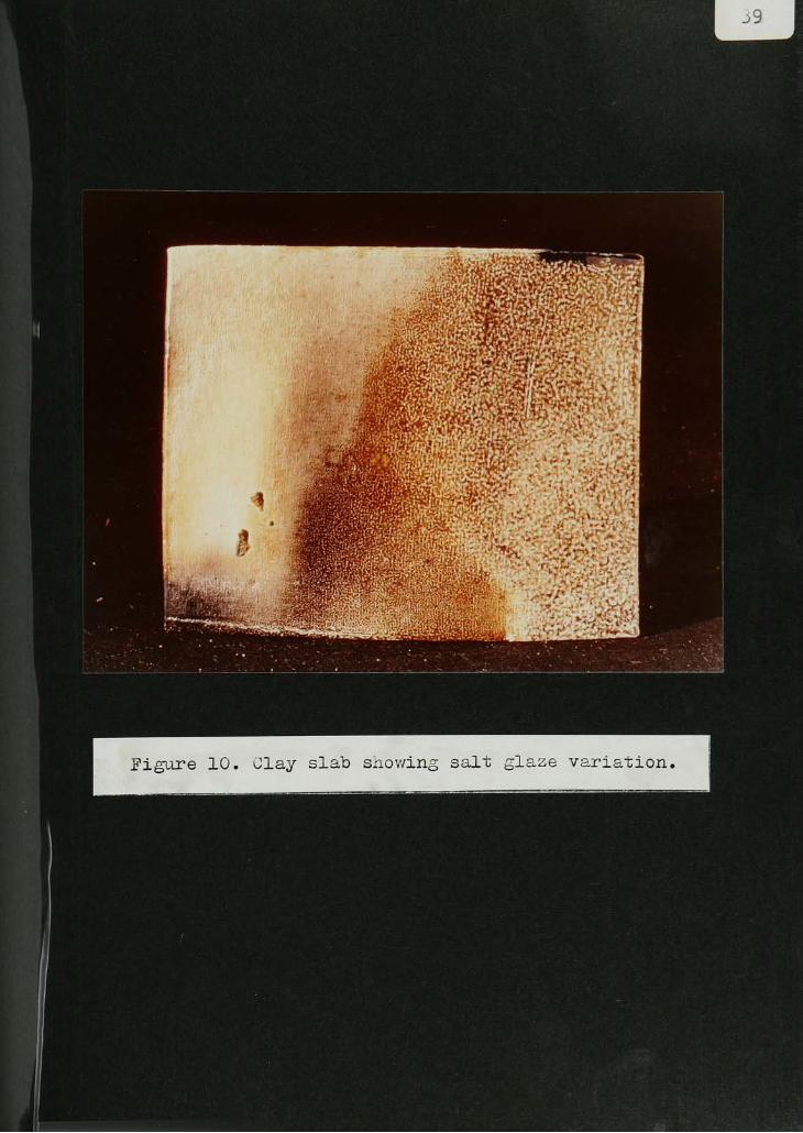
Figure 10. Clay slab siiov/ing salt glaze variation,

I
EEfH^F-/-1 *-. < C u rn- -**
, _.
^>*-> *- :J-S* ^
Figure 12. Tea bowl v/ith Voulkos jrluin glaze,

u03
<d t3 J1 H -H [
3 y. J
o o
^w -p IHd 1
^x j-P o
ain 1^ 1
> O
o ?h<h
t>
03
a<1
4i a lH 3U <h i
t3 1
Ho ;j
!S1
Oj -p 1
H H 1
^) 3 1
CQ
3 <->
3 in 1
H |Ph
, 1^H 1
-P ll
o
X 1
H -H
21
O >
>H
rH
H_P
r^M H-P Pi H
H -H -P
ar-t
<~H 1
J ^a ,q
d fn
> Gj
O
^ 1Xi 3-H 3 !cd , II
H aH^ o
1
d t3
H o
^ ,-J)
3, >H
oD H
H -q d
^4 EH 3i [

42

ll-


m
^H j


50
CONCLUSION
This paper is an accumulation of data gathered
and observations made during my, thesis work .at R.I.T.
My intent, throughout the research, was. not to develop
strict controls or rules pertaining to salt glazing;.
I feel that, considering the nature of the process,
this would be -unwise if not impossible. The character
of the salt kiln is, at times, ao strong that it seems
to have a will of its own, dripping glaze from the top
of its arch onto pots, reducing in certain areas.,
oxidizing in others, darkening pieces that were intended
to be light, and in general, producingresults"
that are
often quite different from those previsualized.
Moreover, my objective was to acquire an understanding
of the many techniques and variables found in the salt
glazing process, thereby, if nothing else, increasing
the odds of my using the medium successfully.
I feel that I have accomplished this goal.

APPENDIX A
Fire Bricks Listed in Order of
Ability to Resist Salt Glazing
51
Rating Brick Identification fi Si02 fi A1203
Excellent Spartan 85
Excellent Alusite-D 23.9 71.3
Good Walsh XX 53 41
Good Woodland X 56.8 37.0
Poor Crescent
Poor King
Poor Keystone
Poor Temple
*
The alumina and silica contents are given where
available .

APPENDIX B
52
TEST SERIES WITH ADDITIONS OF FLINT
E.P.K. Flint fi Absorb.
7.3
Al203/Si02100 1:2.0
ii
5 9.5 1:2.2
n10 10.3 1:2.4
ti
15 10.9 1:2.7
it20 11.6 1:2.9
ii
25 11.8 1:3.1
35 13.9 1:3.3
tt50 14.2 1:4.0
it90 16.0 1:5.9
n 200 16.6 1:11.0
A.P.G. Flint fi Absorb.
3.1
Al203/Si02
100 1:2.5
tt5 4.9 1:2.7
it 10 6.2 1:3.0
ti 15 6.8 1:3.2
ti 20 7.5 1:3.4
n 25 8.4 1:3.6
it 35 9.8 1:4.1
Test
Body Flint fi Absorb.
5.4
AlgO^SiOg
100 1:3.0
tt 3 5.8 1:3.2
it 6 6.2 1:3.4
tt 9 6.7 1:3.6
it 12 7.2 1:3.7
it 15 7.6 1:3.9

APPENDIX B, cont.
53
TEST SERIES WITH ADDITIONS OF FELDSPAR
E.P.K.
Custer
Feldspar fi Absorb.
100 7.3
ti
5 7.0
it10 4.9
1115 3.0
ti25 1.6
ti35 2.5
A.P.G.
Custer
Feldspar fi Absorb.
100 3.1
it 5 2.3
tt 10 1.1
it 20 0.6
it 30 0.0
it 40 0.0
Test
Body
Custer
Feldspar fi Absorb .
100 5.4
it 3 2.9
it 6 2.7
tt 9 2.4
n 12 1.4
it 15 0.9

54
APPENDIX B, cont,
TEST BODY WITH COMBINED ADDITIONS
OF FLINT AND FELDSPAR
Test
BodyFlint/Feldspar fi Absorb. Al203/Si02
100 5.4 1:3.0
2/2 5.1 1:3.2
4/4 4.3 1:3.3
6/6 3.5 1:3.4
8/8 2.7 1:3.5
10/10 2.5 1:3.6
12/12 2.5 1:3.7
*Tha Al O-j/SiOg's given are exclusive of the additions
of feldspar whichcontains little free silica.

55
APPENDIX B,cont.
TEST SERIES WITH ADDITIONS OF PLASTIC VITROX
E.P.K.
Plastic
Vitrox fi Absorb.
100 7.3
115 8.9
it 10 8.3
it15 8.2
it 20 8.1
it 25 7.0
it 30 6.7
it35 5.4
A.P.G.
Plastic
Vitrox fi Absorb.
100 3.1
it 5 4.0
it 10 4.6
tt 15 5.0
it 20 3.6
it 25 3.3
ti 30 3.2
it 35 3.2
Test
Body
Plastic
Vitrox fi Absorb .
100 5.4
ti 3 5.0
ti 6 4.2
ti 9 3.7
u 12 3.7
u 15 2.7

APPENDIX C
Salt Slip
(For application on wet, dry or bisqued ware.)
56
XX Sagger 25
Tenn. #5 Ball 25
Buckingham feldspar 25
Flint 25 j
Rust Brown
100
Red iron oxide
Orange Uranium oxide lOfi
Straw tan Rutile
Green Rutile
Cobalt oxide6fi2fi
Blue Cobalt oxide 2$
Black Chromium oxide
Cobalt oxide
Red iron oxide
Manganese dioxide
Zfi
2fi3fi
3fi
Iridescent-
Green
Titanium dioxide
Cobalt oxidelOfiIfi
Iridescent-
Rust
Titanium dioxide
Red iron oxide
lOfiAfi

57
APPENDIX C, cont.
Rhodes Black Glaze
(midnight blue to black)
Albany 85
Nepheline Syenite 15
100
Cobalt oxide 5fi
Manganese dioxide \fi
Voulkos Plum
(yellow to rich red-brown)
Buckingham feldspar 42.0
Whiting 15.8
Zinc oxide 2.1
Kaolin 9.8
Flint 21.1
Red iron oxide 9.2
100.0

58
APPENDIX C, cont.
Q 10 Satin
(opaque-white, good liner)
Bainbridge feldspar 40
Dolomite 20
Kaolin 20
Flint
100

59
APPENDIX C, cont.
Salt Body #1 Salt Body #2
CH. Goldart 50 CH. Goldart 50
Jordan 25 Tenn. tt5 Ball 25
A.P.G. 25 A.P.G. 25
Feldspar 5 Flint E5
Grog_S
Feldspar#
5
110 Grog
110
Val Cushing Body Alfred School Body
CH. Goldart 25 Jordan 50
E.P.K. 15 Tenn. #5 Ball 25
A.P.G. 15 A.P.G. 15
Tenn. #5 Ball 25 Flint 5
Flint 10 Feldspar 5
Feldspar 10
100
100
Porcelain #1
25
Porcelain #2
E.P.K. E.P.K. 25
Tenn. #5 Ball 25 Tenn. if5 Ball 25
Flint 25 XX Sagger 25
Feldspar 25 Flint 12.5
100 Feldspar 12 . 5
100.0

60
SELECTED BIBLIOGRAPHY
Barringer, L.E. The Relation Between the Constitution
of a Clav and Its Ability to take aGood Salt Glaze.
Transactions of the American Ceramic Society,Vol. IV, (1902), pp. 211-229.
Foster, H.D. "Resume of Technical Studies of SaltGlazing."
Bulletin of the American Ceramic
Society. Vol. XX, (July, 1941), pp. 233-241.
Griffiths, R., and Radford, C Calculations in Ceramics.
London: Maclaren and Sons, Ltd., 1965.
Lee, Sherman E. Tea Taste in Japanese Art. New York:
The Asia Society, inc. , 1953.
Mitsuoka, Tadanari. Shjgaraki, Iga. Bizen, Tamba. No. 20of Toki Zenshu {.Ceramic Series} , Tokyo: 1961.
Norton, F.H. Ceramics for the Artist Potter. Reading,Mass:, Addison-Wesley, 1956.
Parmelee, Cullen W. Ceramic Glazes. Chicago:. Industrial
Publications,1951.'
Rhodes, Daniel. Clay and Glazes for the Potter.
Philadelphia: Chilton, 1957.
Rhodes, Daniel. Kilns. Philadelphia: Chilton, 1968.
Schurecht, H.G. "Salt Glazing of Ceramic Ware."
Bulletin of the American Ceramic Society, Vol. XXII,(Febuary, 1943;, pp. 45-46.
Thesis Source Book:
Turabian ,Kate L . A Manual for Writers of Term Papers.Theses, and Dissertations. 3rd. ed. Chicago:.
The University of Chicago Press, 1967.