Embed Size (px)
Citation preview
Floor Standing TypeAir ConditionerSERVICE MANUALMODEL: LP-K Series
Contents
Functions 3
Product Specifications 6
Dimensions 7
Refrigeration Cycle Diagram 7
Wiring Diagram 8
Operation Details 12
Installation of Indoor, Outdoor Unit 19
Test Running 30
3-way Valve 32
Cycle Troubleshooting Guide 38
Electronic Parts Troubleshooting Guide 39
Electronic Control Device 42
Schematic Diagram 43
Exploded View and Replacement Parts List 44
–2–
–3–
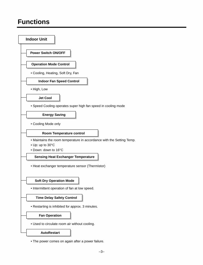
Indoor Unit
Power Switch ON/OFF
Operation Mode Control
Indoor Fan Speed Control
Jet Cool
Energy Saving
Room Temperature control
Sensing Heat Exchanger Temperature
Soft Dry Operation Mode
Time Delay Safety Control
Fan Operation
AutoRestart
• Cooling, Heating, Soft Dry, Fan
• High, Low
• Speed Cooling operates super high fan speed in cooling mode
• Cooling Mode only
• Maintains the room temperature in accordance with the Setting Temp.
• Up: up to 30°C
• Down: down to 16°C
• Heat exchanger temperature sensor (Thermistor)
• Intermittent operation of fan at low speed.
• Restarting is inhibited for approx. 3 minutes.
• Used to circulate room air without cooling.
• The power comes on again after a power failure.
Functions
–4–
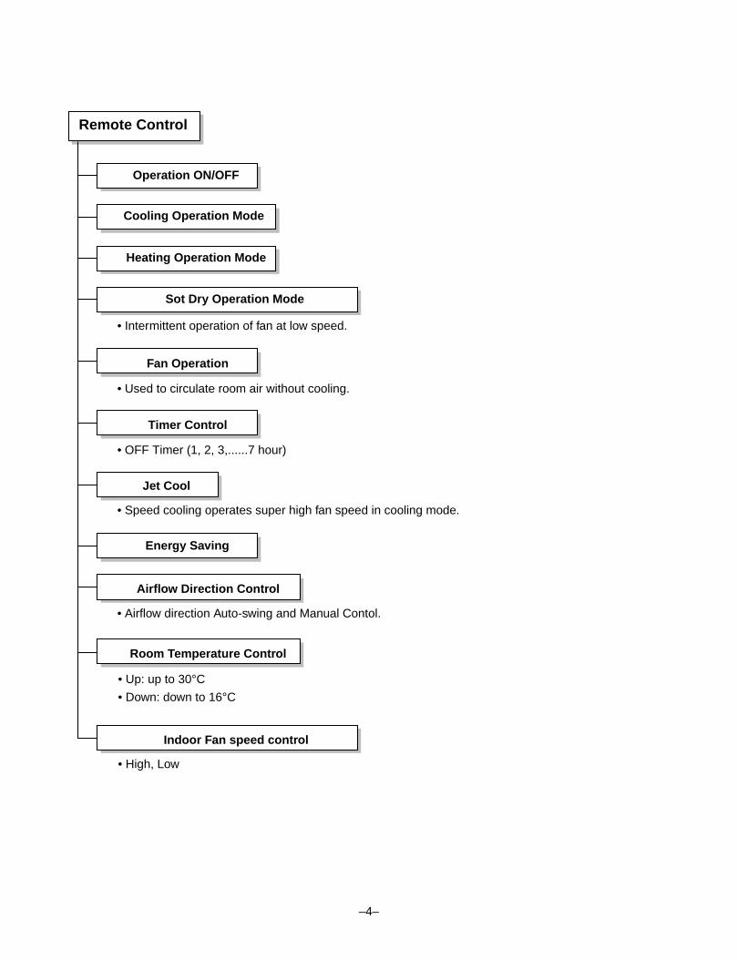
• Intermittent operation of fan at low speed.
• Used to circulate room air without cooling.
• OFF Timer (1, 2, 3,......7 hour)
• Speed cooling operates super high fan speed in cooling mode.
• Airflow direction Auto-swing and Manual Contol.
• Up: up to 30°C
• Down: down to 16°C
• High, Low
Remote Control
Operation ON/OFF
Cooling Operation Mode
Heating Operation Mode
Sot Dry Operation Mode
Fan Operation
Timer Control
Jet Cool
Energy Saving
Airflow Direction Control
Room Temperature Control
Indoor Fan speed control
–5–
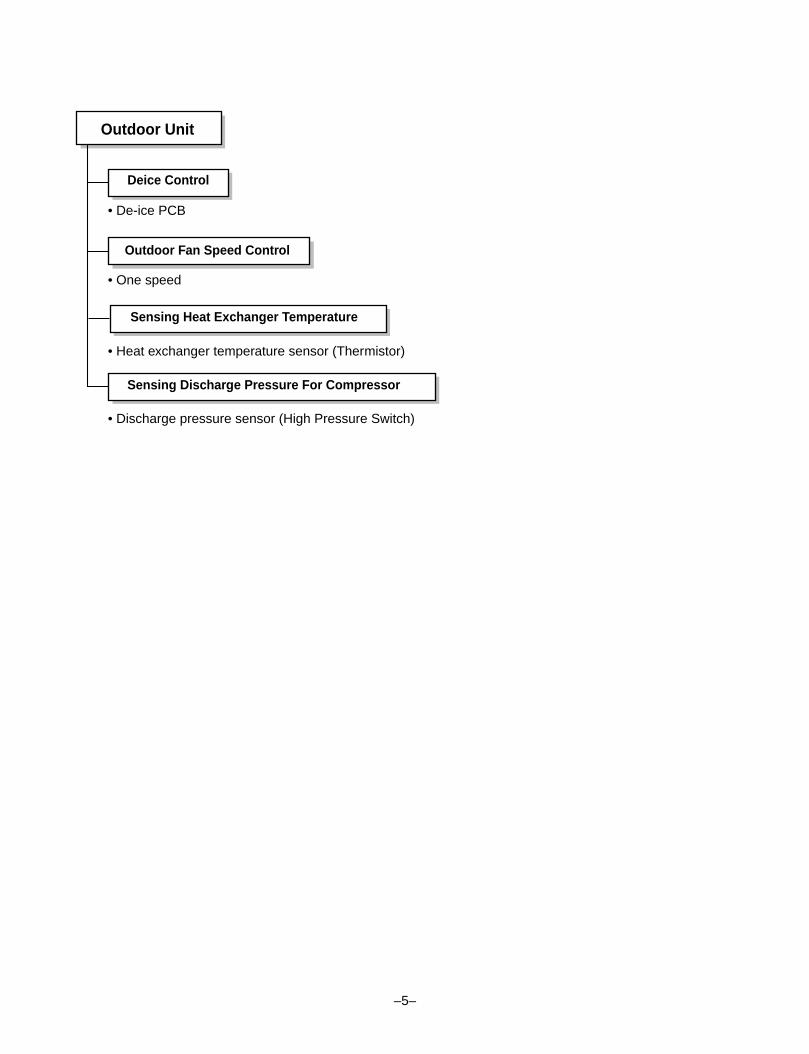
Outdoor Unit
Deice Control
Outdoor Fan Speed Control
Sensing Heat Exchanger Temperature
Sensing Discharge Pressure For Compressor
• De-ice PCB
• One speed
• Heat exchanger temperature sensor (Thermistor)
• Discharge pressure sensor (High Pressure Switch)
Product Specifications
–6–
POWER SUPPLY Ø, V, Hz
COOLING CAPACITY Btu/hr
HEATING CAPACITY Btu/hr(Incl. elec. Heater)
POWER INPUT COOLING W
HEATING W
RUNNING COOLING A
CURRENT HEATING A
MODEL
MAKER
TYPE
COMPRESSOR CAPACITY Btu/hr
INPUT (KW)
LRA A
NOISE LEVEL INDOOR dB(A)
OUTDOOR dB(A)
AIR INDOOR CFM/CMM
CIRCULATION OUTDOOR CFM/CMM
REFRIGERANT (R-22) OZ(kg)
HEAT INDOOR R/C/FPI
EXCHANGER OUTDOOR R/C/FPI
FAN INDOOR TYPE
OUTDOOR TYPE
ROOM TEMPERATURE CONTROL
WIDTH
INDOOR HEIGHT inch(mm)
DEPTH
WIDTH
OUTDOOR HEIGHT inch(mm)
DEPTH
NET WEIGHTINDOOR Ib(kg)
OUTDOOR Ib(kg)
CONNECTIONS LIQUID inch(mm)
GAS inch(mm)
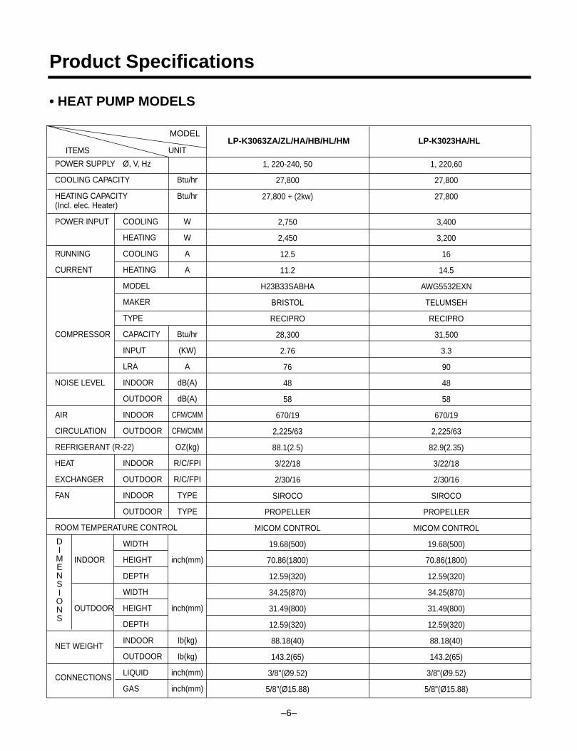
1, 220-240, 50
27,800
27,800 + (2kw)
2,750
2,450
12.5
11.2
H23B33SABHA
BRISTOL
RECIPRO
28,300
2.76
76
48
58
670/19
2,225/63
88.1(2.5)
3/22/18
2/30/16
SIROCO
PROPELLER
MICOM CONTROL
19.68(500)
70.86(1800)
12.59(320)
34.25(870)
31.49(800)
12.59(320)
88.18(40)
143.2(65)
3/8"(Ø9.52)
5/8"(Ø15.88)
1, 220,60
27,800
27,800
3,400
3,200
16
14.5
AWG5532EXN
TELUMSEH
RECIPRO
31,500
3.3
90
48
58
670/19
2,225/63
82.9(2.35)
3/22/18
2/30/16
SIROCO
PROPELLER
MICOM CONTROL
19.68(500)
70.86(1800)
12.59(320)
34.25(870)
31.49(800)
12.59(320)
88.18(40)
143.2(65)
3/8"(Ø9.52)
5/8"(Ø15.88)
ITEMS UNIT
MODELLP-K3023HA/HLLP-K3063ZA/ZL/HA/HB/HL/HM
DIMENSIONS
• HEAT PUMP MODELS
–7–
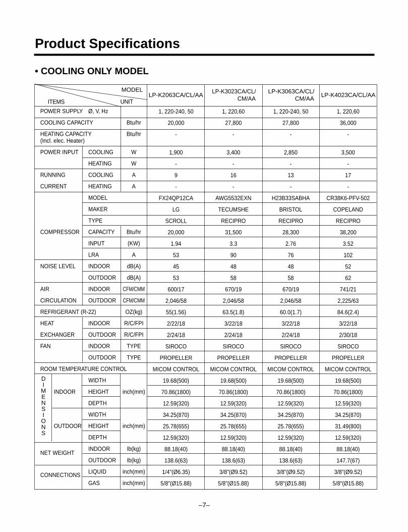
Product Specifications
• COOLING ONLY MODEL
POWER SUPPLY Ø, V, Hz
COOLING CAPACITY Btu/hr
HEATING CAPACITY Btu/hr(Incl. elec. Heater)
POWER INPUT COOLING W
HEATING W
RUNNING COOLING A
CURRENT HEATING A
MODEL
MAKER
TYPE
COMPRESSOR CAPACITY Btu/hr
INPUT (KW)
LRA A
NOISE LEVEL INDOOR dB(A)
OUTDOOR dB(A)
AIR INDOOR CFM/CMM
CIRCULATION OUTDOOR CFM/CMM
REFRIGERANT (R-22) OZ(kg)
HEAT INDOOR R/C/FPI
EXCHANGER OUTDOOR R/C/FPI
FAN INDOOR TYPE
OUTDOOR TYPE
ROOM TEMPERATURE CONTROL
WIDTH
INDOOR HEIGHT inch(mm)
DEPTH
WIDTH
OUTDOOR HEIGHT inch(mm)
DEPTH
NET WEIGHTINDOOR Ib(kg)
OUTDOOR Ib(kg)
CONNECTIONS LIQUID inch(mm)
GAS inch(mm)
1, 220-240, 50
20,000
-
1,900
-
9
-
FX24QP12CA
LG
SCROLL
20,000
1.94
53
45
53
600/17
2,046/58
55(1.56)
2/22/18
2/24/18
SIROCO
PROPELLER
MICOM CONTROL
19.68(500)
70.86(1800)
12.59(320)
34.25(870)
25.78(655)
12.59(320)
88.18(40)
138.6(63)
1/4"(Ø6.35)
5/8"(Ø15.88)
1, 220,60
27,800
-
3,400
-
16
-
AWG5532EXN
TECUMSHE
RECIPRO
31,500
3.3
90
48
58
670/19
2,046/58
63.5(1.8)
3/22/18
2/24/18
SIROCO
PROPELLER
MICOM CONTROL
19.68(500)
70.86(1800)
12.59(320)
34.25(870)
25.78(655)
12.59(320)
88.18(40)
138.6(63)
3/8"(Ø9.52)
5/8"(Ø15.88)
1, 220-240, 50
27,800
-
2,850
-
13
-
H23B33SABHA
BRISTOL
RECIPRO
28,300
2.76
76
48
58
670/19
2,046/58
60.0(1.7)
3/22/18
2/24/18
SIROCO
PROPELLER
MICOM CONTROL
19.68(500)
70.86(1800)
12.59(320)
34.25(870)
25.78(655)
12.59(320)
88.18(40)
138.6(63)
3/8"(Ø9.52)
5/8"(Ø15.88)
1, 220,60
36,000
-
3,500
-
17
-
CR38K6-PFV-502
COPELAND
RECIPRO
38,200
3.52
102
52
62
741/21
2,225/63
84.6(2.4)
3/22/18
2/30/18
SIROCO
PROPELLER
MICOM CONTROL
19.68(500)
70.86(1800)
12.59(320)
34.25(870)
31.49(800)
12.59(320)
88.18(40)
147.7(67)
3/8"(Ø9.52)
5/8"(Ø15.88)
ITEMS UNIT
MODELLP-K2063CA/CL/AA
LP-K3023CA/CL/CM/AA
LP-K3063CA/CL/CM/AA
LP-K4023CA/CL/AA
DIMENSIONS
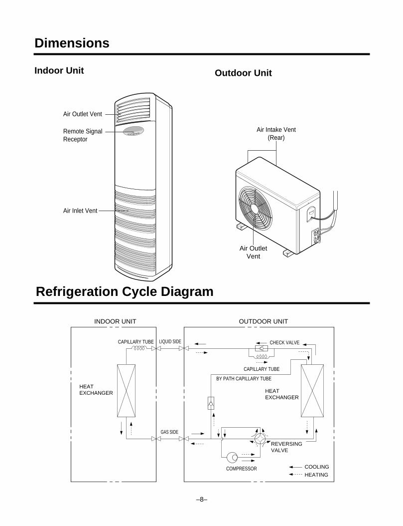
Dimensions
Indoor Unit
Air Outlet Vent
Remote Signal Receptor
Air Inlet Vent
Air Intake Vent(Rear)
Air OutletVent
INDOOR UNIT OUTDOOR UNIT
HEATEXCHANGER HEAT
EXCHANGER
COMPRESSOR
GAS SIDE
LIQUID SIDE
COOLING
HEATING
REVERSINGVALVE
CHECK VALVECAPILLARY TUBE
CAPILLARY TUBE
BY PATH CAPILLARY TUBE
–8–
Outdoor Unit
Refrigeration Cycle Diagram
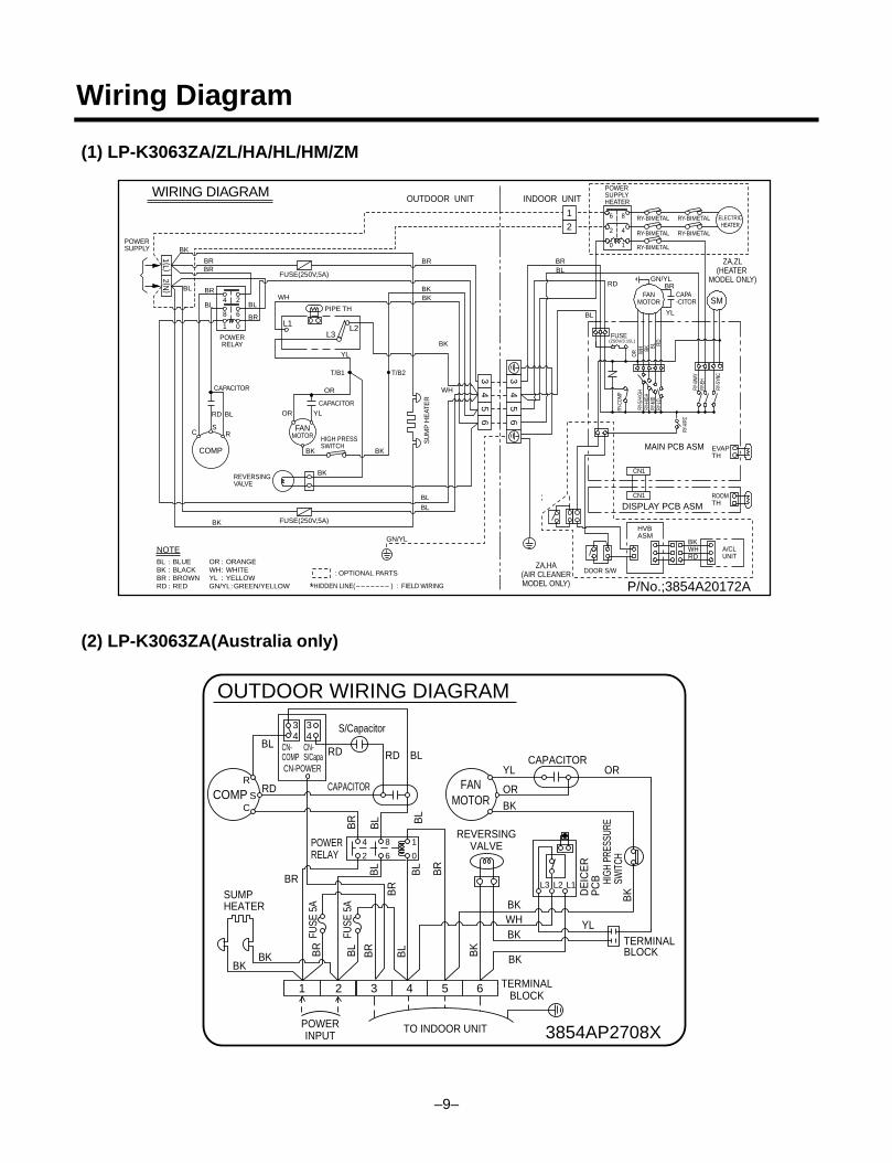
Wiring Diagram
(1) LP-K3063ZA/ZL/HA/HL/HM/ZM
(2) LP-K3063ZA(Australia only)
WIRING DIAGRAM OUTDOOR UNIT INDOOR UNIT
P/No.;3854A20172A*HIDDEN LINE( - - - - - - - ) : FIELD WIRING
: OPTIONAL PARTS
NOTEBLBKBRRD
BLUEBLACKBROWNRED
::::
ORWHYLGN/YL
ORANGEWHITEYELLOW GREEN/YELLOW
::: :
RY-C
OMP
RY-S
/HIG
HRY
-HIG
HRY
-MID
RY-L
O
OR W
H BK BL RD
RY-4
WAY
RY-A
IRC
RY-E
H
RY-S
YNC
CAPA-CITOR
ZA,ZL(HEATER
MODEL ONLY)
ZA,HA(AIR CLEANERMODEL ONLY)
FUSE(250V/3.15L)
POWERSUPPLYHEATER
SM
DISPLAY PCB ASM
MAIN PCB ASM
FANMOTOR
6 8
2 4
0 1
DOOR S/W
BKWHRD
HVBASM
CN1
EVAPTH
ROOMTH
CN1
A/CLUNIT
RY-BIMETAL
RY-BIMETAL
RY-BIMETAL ELECTRICHEATER
RY-BIMETAL
RY-BIMETALPOWERSUPPLY
POWERRELAY
T/B1 T/B2
SU
MP
HE
ATE
R
COMP
FANMOTOR
BR
BK
BR
BR
BL
BL
BL
BR
WH
OR
ORRD BL
CS
R
BK BK
BL
GN/YL
WH
BL
YL
HIGH PRESSSWITCH
REVERSINGVALVE
BK
BK
CAPACITOR
CAPACITOR
YL
BK
BKBK
BR
RD
BL
BL
GN/YL
YL
BR
BR
PIPE TH
L1L3
L2
4 2
8 6
1 0
FUSE(250V,5A)
FUSE(250V,5A)
1 (L )2 (N
)
1
2
35
46
35
46
4
3854AP2708X
OUTDOOR WIRING DIAGRAM
8 1
2 6
L3 L2 L1
0
R
CS
5 61 32 4
CAPACITOR
S/Capacitor
RD
BL
BR
BR
BK
SUMPHEATER
BK
BL
BL
BLRDRDBL
BL
BR
BK
BR
BL
BR
BK
HIGH
PRE
SSUR
ESW
ITCH
DE
ICE
RP
CB
BR
BL
POWERINPUT
TO INDOOR UNIT
TERMINALBLOCK
TERMINALBLOCK
FUSE
5A
FUSE
5A
POWERRELAY
REVERSINGVALVE
COMP
CAPACITORYL OR
OR
BK
BK
BK
BKWH YL
FANMOTOR
3
CN-COMP
CN-S/Capa
CN-POWER
434
–9–
–10–
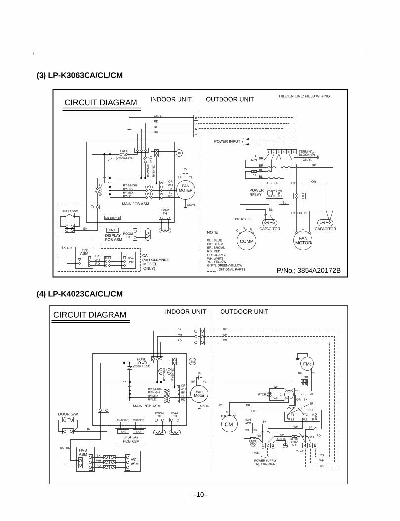
(3) LP-K3063CA/CL/CM
(4) LP-K4023CA/CL/CM
INDOOR UNIT OUTDOOR UNIT
DISPLAYPCB ASM
MAIN PCB ASM
RY-S/HIGH
RY-
AIR
C
BK
CN-DISP(1)
CN1ROOM
TH
DOOR S/W
BK RD
BKWHRD
HVBASM
A/CL
UNIT
OR
BR YL
Cr
WHBKBLRD
GN/YL
RY-
CO
MP
RY-
SY
NC
(250V/3.15L)
SM
EVAPTH
RY-HIGHRY-MIDRY-LO
RD
GN/YL
BL
BR
FUSE
P/No.; 3854A20172B
CIRCUIT DIAGRAM
FANMOTER
COMP.
POWERRELAY
POWER INPUT
HIDDEN LINE: FIELD WIRING
CAPACITOR
BR
BRBLBR OR
BRBL
BL
TERMINALBLOCK(6P)
1F1
F2
2 3 4
GN/YL
5 6
BK
BL
BL
BK
BK
BR
C RS
RD BL
OR YL
2 6
4 8
0
1
CAPACITOR
FANMOTOR
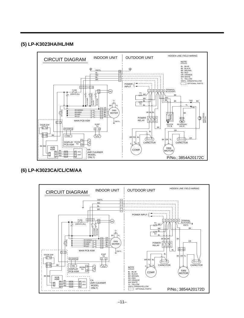
NOTE
BLBKBRRDORWHYLGN/YL:GREEN/YELLOW : OPTIONAL PARTS
BLUEBLACKBROWNREDORANGEWHITEYELLOW
:::::::
CA(AIR CLEANER MODEL ONLY)
34
56
DISPLAYPCB ASM
HVBASM
A/CLASM
RY-S/HIGHOR
BR YL
GN/YL
Ci
WHBKBLRD
RY-
CO
MP
RY-
SY
NC
(250V 3.15A)
SM
FanMotor
CM
EVAPTH
RY-HIGHRY-MIDRY-LD
CN-DISP(1)
CN1 CN2
CN-DISP(2)
ROOMTH
BK
WH
RD
BK
WH
RD
POWER SUPPLY1ø, 220V, 60Hz
Tmo1
1 2 3 4 5 6
L1
T1
L2
T2
52C
B
A
RD
WH
BR
BK
BK WH
WH
Tmo2
RD
RD
WH
BK
WH
GN/YL
RD
RD
BK
BK63H
FUSE250V5 A
WH
R
SC
WH
PTCR Cr
BK
FUSE250V5 A
FUSE
MAIN PCB ASM
BK
BK RD
BK
WH
RD
DOOR S/W
FMo
OR BKBR
YL
Co
OR
INDOOR UNIT OUTDOOR UNIT CIRCUIT DIAGRAM
–11–
(6) LP-K3023CA/CL/CM/AA
INDOOR UNIT OUTDOOR UNIT
DISPLAYPCB ASM
MAIN PCB ASM
RY-S/HIGH
RY-
AIR
C
BK
CN-DISP(1)
CN1
ROOMTH
DOOR S/W
BK RD
BKWHRD
HVBASM
A/CL
UNIT
OR
BR YL
Cr
WHBKBLRD
GN/YL
RY-
CO
MP
RY-
RE
VE
RS
ING
VA
LVE
RY-
SY
NC
(250V/3.15L)
SM
EVAPTH
RY-HIGHRY-MIDRY-LO
RDBLGN/YL
BLBR
FUSE
P/No.; 3854A20172C
CIRCUIT DIAGRAM
FANMOTER
COMP.
POWERRELAY
POWERINPUT
HIDDEN LINE: FIELD WIRING
CAPACITOR
BR
BLBLBR
BRBL
BL
TERMINALBLOCK(6P) 1
F1
F2
2 3 4 5 6
BR
BL
BK
WHBK BKBK
YL
BKBR
C RS
RD BLOR
OR
YL
2 6
4 8
0
1
CAPACITOR
FANMOTOR
NOTE
BLBKBRRDORWHYLGN/YL: GREEN/YELLOW : OPTIONAL PARTS
BLUEBLACKBROWNREDORANGEWHITEYELLOW
:::::::
L1 L2 L3
HIG
H P
RE
SS
SW
ITC
H
T/B2
REVERSINGVALVE
DEICERP.C.B
OR
BK
HA(AIR CLEANER MODEL ONLY)
34
56
T/B1
INDOOR UNIT OUTDOOR UNIT
DISPLAYPCB ASM
MAIN PCB ASM
RY-S/HIGH
RY-
AIR
C
BK
CN-DISP(1)
CN1ROOM
TH
DOOR S/W
BK RD
BKWHRD
HVBASM
A/CL
UNIT
OR
BR YL
Cr
WHBKBLRD
GN/YL
RY-
CO
MP
RY-
SY
NC
(250V/3.15L)
SM
EVAPTH
RY-HIGHRY-MIDRY-LO
RD
GN/YL
BL
BR
FUSE
P/No.; 3854A20172D
CIRCUIT DIAGRAM
FANMOTER
COMP.
POWERRELAY
POWER INPUT
HIDDEN LINE: FIELD WIRING
CAPACITOR
BR
BRBLBROR
BRBL
BL
TERMINALBLOCK(6P)
1F1
F2
2 3 4
GN/YL
5 6
BK
BL
BL
BK
BK
BR
C RS
RD BL
OR YL
2 6
4 8
0
1
CAPACITOR
FANMOTOR
NOTE
CA(AIR CLEANER MODEL ONLY)
BLBKBRRDORWHYLGN/YL:GREEN/YELLOW : OPTIONAL PARTS
BLUEBLACKBROWNREDORANGEWHITEYELLOW
:::::::
34
56
(5) LP-K3023HA/HL/HM
–12–
(1) The function of main control
1. Time Delay Safety Control3min The compressor is ceased for 3 minutes to balance the pressure in the refrigeration cycle.
(Protection of compressor)
3sec The indoor fan is ceased for 3 seconds to prevent relay noise.
(Protection of fan relay and micro chip)
30sec The 4-way valve is ceased for 30 sec. to prevent the refrigerant-gas abnormal noise when the Heatingoperation is OFF or switched to the other operation mode.
2. Airflow Direction ControlThis function is to swing the louver left and right automatically and to set it at the desired position.
The procedure is as the following.
1st : Press the ON/OFF Button to operate the product.
2nd : Press the Airflow Direction Control Button to swing the louver left and right automatically.(Remote controller)
3rd : Repress the Airflow Direction Control Button to set the louver as the desired position.(Remote controller)
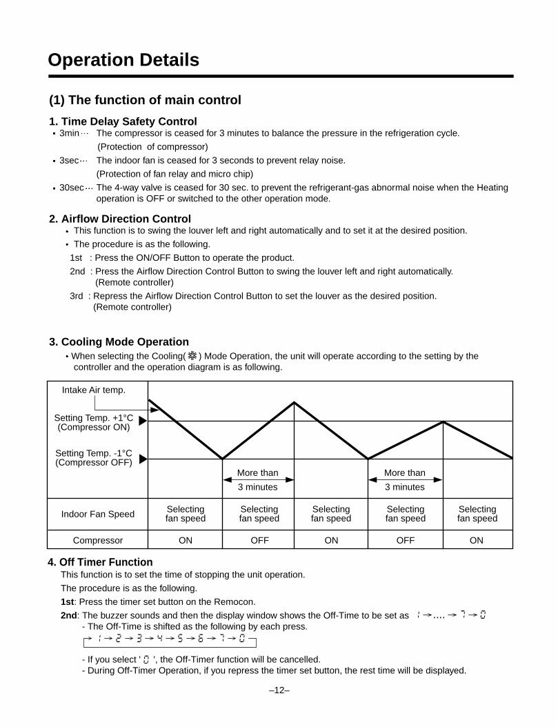
3. Cooling Mode OperationWhen selecting the Cooling( ) Mode Operation, the unit will operate according to the setting by thecontroller and the operation diagram is as following.
Intake Air temp.
Setting Temp. +1°C(Compressor ON)
Setting Temp. -1°C(Compressor OFF)
Indoor Fan Speed Selectingfan speed
Selectingfan speed
Selectingfan speed
Selectingfan speed
Selectingfan speed
3 minutes
More than
3 minutes
More than
Compressor ON OFF ON OFF ON
Operation Details
4. Off Timer FunctionThis function is to set the time of stopping the unit operation.
The procedure is as the following.
1st: Press the timer set button on the Remocon.
2nd: The buzzer sounds and then the display window shows the Off-Time to be set as- The Off-Time is shifted as the following by each press.
- If you select ' ', the Off-Timer function will be cancelled.- During Off-Timer Operation, if you repress the timer set button, the rest time will be displayed.
....
–13–
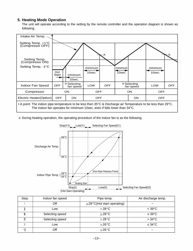
5. Heating Mode OperationThe unit will operate according to the setting by the remote controller and the operation diagram is shown asfollowing.
Intake Air Temp.
Setting Temp.(Compressor ON)
Setting Temp. -1°C
Indoor Fan Speed
Compressor
Electric Heater(Option)
ON
ON
OFF ON OFF
OFFOFF ON OFF
OFF
HotStart
minimum
10sec.minimum
10sec.
minimum
10sec.
minimum
10sec.
OFF
A A
OFFLOW LOW
Setting Temp. +1°C(Compressor OFF)
Selecting fan speed
Selecting fan speed
• A point: The indoor pipe temperature to be less then 35°C & Discharge air Temperature to be less than 29°C.The indoor fan operates for minimum 10sec. even if falls lower than 34°C.
Low(V)Stop(VI)
39˚C
Discharge Air Temp.
Indoor Pipe Temp.
34˚C
28˚C26˚C
Selecting Fan Speed(IV)
Low(II)Stop(I)(Hot-Start Operating)
Heating Start
(Hot-Start Release Point)
Selecting Fan Speed(III)
During heating operation, the operating procedure of the indoor fan is as the following.
Step Indoor fan speed Pipe temp. Air discharge temp.
Off 28 C(Hot start operating)
Low 28 C < 39°C
Selecting speed 28 C ≥ 39°C
Selecting speed 28 C > 34°C
Low 26 C ≤ 34°C
Off 26 C
–14–
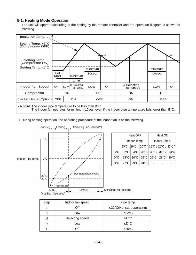
5-1. Heating Mode OperationThe unit will operate according to the setting by the remote controller and the operation diagram is shown asfollowing.
Intake Air Temp.
Setting Temp.(Compressor ON)
Setting Temp. -1°C
Indoor Fan Speed
Compressor
Electric Heater(Option)
ON
ON
OFF ON OFF
OFFOFF ON OFF
OFF
HotStart
minimum
10sec.minimum
1min
minimum
10sec.
OFF
A A
OFFLOWLOW LOW
Setting Temp. +1°C(Compressor OFF)
Selecting fan speed
Selectingfan speed
• A point: The indoor pipe temperature to be less than B°C.The indoor fan operates for minimum 10sec. even if the indoor pipe temperature falls lower than B°C.
Low(V)Stop(VI)
C˚C
Indoor Pipe Temp. D˚C
22˚C20˚C
Selecting Fan Speed(IV)
Low(II)Stop(I)(Hot-Start Operating)
Heating Start
(Hot-Start Release Point)
Selecting Fan Speed(III)
During heating operation, the operating procedure of the indoor fan is as the following.
Step Indoor fan speed Pipe temp.
Off ≤22°C(Hot start operating)
Low ≥22°C
Selecting speed ≥C°C
Low ≤D°C
Off ≤20°C
Heat OFF Heat ON
Indoor Temp. Indoor Temp.
15°C 20°C 20°C 15°C 20°C 20°C
C°C 32°C 34°C 36°C 30°C 31°C 33°C
D°C 28°C 30°C 32°C 26°C 28°C 30°C
B°C 27°C 29°C 31°C - - -
–15–
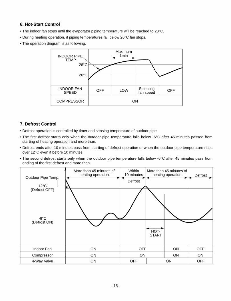
6. Hot-Start Control• The indoor fan stops until the evaporator piping temperature will be reached to 28°C.
• During heating operation, if piping temperatures fall below 26°C fan stops.
• The operation diagram is as following.
7. Defrost Control• Defrost operation is controlled by timer and sensing temperature of outdoor pipe.
• The first defrost starts only when the outdoor pipe temperature falls below -6°C after 45 minutes passed fromstarting of heating operation and more than.
• Defrost ends after 10 minutes pass from starting of defrost operation or when the outdoor pipe temperature risesover 12°C even if before 10 minutes.
• The second defrost starts only when the outdoor pipe temperature falls below -6°C after 45 minutes pass fromending of the first defrost and more than.
INDOOR PIPETEMP.
INDOOR FANSPEED
Selectingfan speedOFF OFFLOW
1minMaximum
COMPRESSOR ON
28°C
26°C
More than 45 minutes ofheating operation
Outdoor Pipe Temp.
Indoor Fan
Compressor
4-Way Valve
ON
ON
ON
ON
OFF
ON
OFF
HOT-START
ON
ON OFF OFFON
12°C(Defrost OFF)
-6°C(Defrost ON)
Within 10 minutes
Defrost
DefrostMore than 45 minutes of
heating operation
–16–
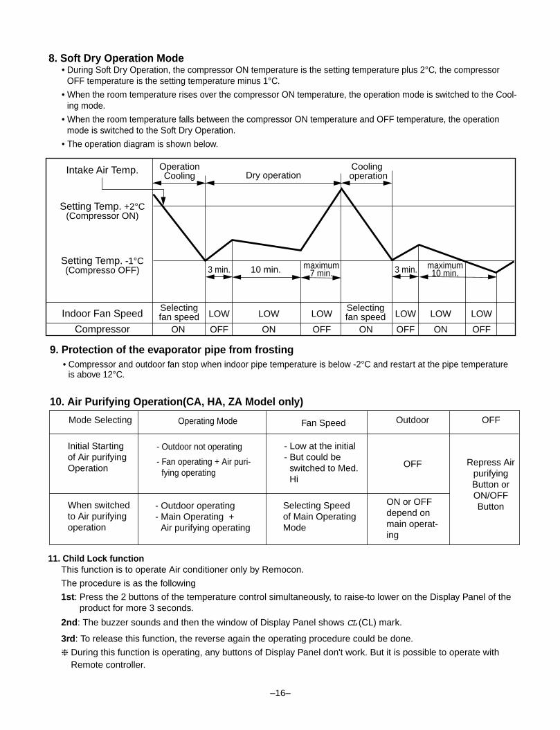
11. Child Lock functionThis function is to operate Air conditioner only by Remocon.
The procedure is as the following
1st: Press the 2 buttons of the temperature control simultaneously, to raise-to lower on the Display Panel of theproduct for more 3 seconds.
2nd: The buzzer sounds and then the window of Display Panel shows CCLL (CL) mark.
3rd: To release this function, the reverse again the operating procedure could be done.
❈ During this function is operating, any buttons of Display Panel don't work. But it is possible to operate withRemote controller.
9. Protection of the evaporator pipe from frosting• Compressor and outdoor fan stop when indoor pipe temperature is below -2°C and restart at the pipe temperature
is above 12°C.
10. Air Purifying Operation(CA, HA, ZA Model only)
8. Soft Dry Operation Mode• During Soft Dry Operation, the compressor ON temperature is the setting temperature plus 2°C, the compressor
OFF temperature is the setting temperature minus 1°C.
• When the room temperature rises over the compressor ON temperature, the operation mode is switched to the Cool-ing mode.
• When the room temperature falls between the compressor ON temperature and OFF temperature, the operationmode is switched to the Soft Dry Operation.
• The operation diagram is shown below.
Intake Air Temp.
Indoor Fan Speed LOWSelectingfan speed
Selectingfan speedLOW LOW LOW LOW
Compressor OFFON ONON OFF OFF ON
LOW
OFF
Setting Temp. +2°C(Compressor ON)
Setting Temp. -1°C(Compresso OFF)
OperationCooling
CoolingoperationDry operation
3 min. 3 min.10 min. maximum7 min.
maximum10 min.
Mode Selecting Operating Mode Fan Speed Outdoor OFF
Initial Startingof Air purifyingOperation
- Low at the initial- But could be
switched to Med.Hi
OFF
- Outdoor not operating
- Fan operating + Air puri-fying operating
Repress AirpurifyingButton orON/OFFButtonWhen switched
to Air purifyingoperation
Selecting Speedof Main OperatingMode
ON or OFFdepend onmain operat-ing
- Outdoor operating- Main Operating +
Air purifying operating
12. Alarm mode display / only displayed while operating.
CCOO : The sensor for sensing room temperature is open or short.
CC11: The sensor for sensing piping temperature is open or short.
13. Jet Cool❏ During the JET COOL function at any moment, the A/C starts to blow the cool air at extremely high speed
setting the room temp. automatically to 18°C. It is especially used to cool the room temp. in the shortest timein a hot summer.In heat pump mode or neuro fuzzy mode however, the JET COOL function is not available.
❏ You can select this function during the operation of Cooling/ Soft Dry/ Auto/ Fan.
❏ When it is selected, JET COOL lamp is on immediately and fan speed graphic(red) is on 3 times off.
❏ Possible to select or cancel using JET COOL key.
❏ To cancel the JET COOL Mode, press the JET COOL button again or the Fan Speed button or the RoomTemperature Setting button and the unit will operate in high Fan speed on Cooling mode(set up to 18°C).
❏ During the operation when it stops and runs again setting up is high fan speed on cooling mode(set up to18°C).
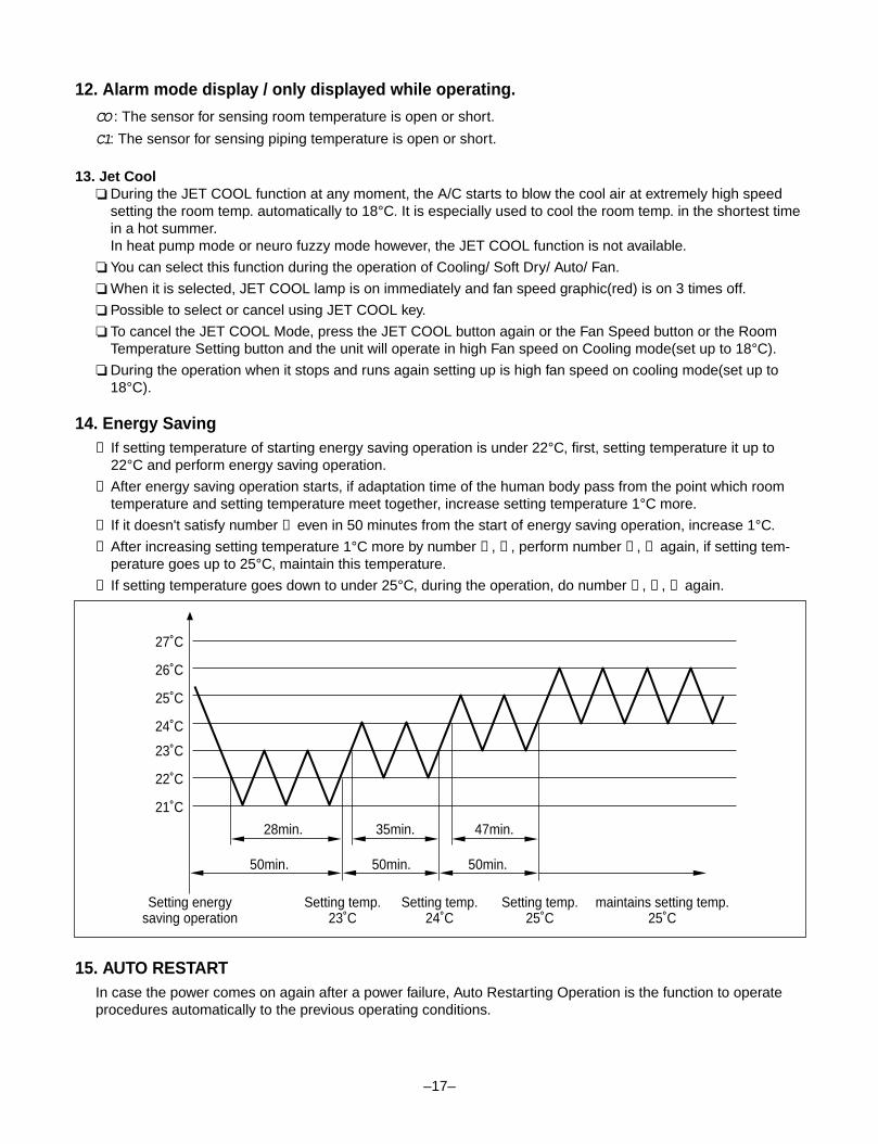
14. Energy Saving➀ If setting temperature of starting energy saving operation is under 22°C, first, setting temperature it up to
22°C and perform energy saving operation.
➁ After energy saving operation starts, if adaptation time of the human body pass from the point which roomtemperature and setting temperature meet together, increase setting temperature 1°C more.
➂ If it doesn't satisfy number ➀ even in 50 minutes from the start of energy saving operation, increase 1°C.
➃ After increasing setting temperature 1°C more by number ➀ , ➁ , perform number ➁ , ➂ again, if setting tem-perature goes up to 25°C, maintain this temperature.
➄ If setting temperature goes down to under 25°C, during the operation, do number ➁ , ➂ , ➃ again.
15. AUTO RESTARTIn case the power comes on again after a power failure, Auto Restarting Operation is the function to operateprocedures automatically to the previous operating conditions.
–17–
Setting energysaving operation
Setting temp.23˚C
21˚C
22˚C
23˚C
24˚C
25˚C
26˚C
27˚C
Setting temp.24˚C
Setting temp.25˚C
maintains setting temp.25˚C
28min.
50min. 50min. 50min.
35min. 47min.
16. Function of changing set temperature when re-operation after stop.Operation is set the following condition when re-operation with start/stop button.
1.Operation mode.Cooling/soft dry mode Cooling modeHeating mode Heating mode
2. Setting the set temperature when cooling operation.Room temperature > Set temperature: to be set to the previous set temperature.Room temperature ≤ Set temperaturea) Room temperature ≥ 26°C: to be set to 24°Cb) 22°C ≤ Room temperature ≤ 25°C: to be set to 21°Cc) 19°C ≤ Room temperature ≤ 21°C: to be set to -1°C less than room temperature.d) Room temperature ≤ 18°C: to be set to 18°C
3. Setting the set temperature when heating operation.Room temperature < Set temperature: to be set to the previous set temperature.Room temperature ≥ Set temperaturea) Room temperature ≤ 20°C: to be set to 23°Cb) 21°C ≤ Room temperature ≤ 25°C: to be set to 26°Cc) 26°C ≤ Room temperature ≤ 28°C: to be set to +1°C more than room temperature.d) 29°C ≤ Room temperature : to be set to 30°C
17. Function for test operation1) Outline of Operation- This is for checking the condition of installation during the installation, and it is operated by cooling, Fan speed
is high, comp. on, and Auto air flow operations without setting temperature.
2) Operation or Cancel- Do test operation, if you push ON/OFF button and the down room temperature checking button over 3 sec-
onds at the same time.
- During the operation, if you push the stop button or push ON/OFF button and the down room temperaturechecking button over 3 seconds at the same time, the test operation will be cancelled and unit come to rest.
- During the operation, if you input remocon key or key on Display panel, it performs its duties.
3) Function- It operates cooling, fan speed is high, auto air flow operation, comp. on for 18 ± 1 minutes, regardless of room
temperature.
- After 18 ± 1 minutes of operation, it becomes off itself.
- During the operation, signal 8888stands for "LLoo"
–18–
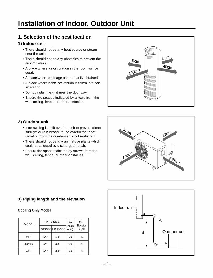
1. Selection of the best location1) Indoor unit
• There should not be any heat source or steamnear the unit.
• There should not be any obstacles to prevent theair circulation.
• A place where air circulation in the room will begood.
• A place where drainage can be easily obtained.
• A place where noise prevention is taken into con-sideration.
• Do not install the unit near the door way.
• Ensure the spaces indicated by arrows from thewall, ceiling, fence, or other obstacles.
2) Outdoor unit• If an awning is built over the unit to prevent direct
sunlight or rain exposure, be careful that heatradiation from the condenser is not restricted.
• There should not be any animals or plants whichcould be affected by discharged hot air.
• Ensure the space indicated by arrows from thewall, ceiling, fence, or other obstacles.
–19–
Installation of Indoor, Outdoor Unit
50cm
50cm
50cm
100cm
5cm5cm
40cm
100cm
A
B
Indoor unit
Outdoor unit
3) Piping length and the elevation
Cooling Only Model
5/8" 1/4" 30 20
5/8" 3/8" 30 20
5/8" 3/8" 30 20
20K
28K/30K
40K
PIPE SIZEMODEL
GAS SIDE LIQUID SIDE
Max.LengthA (m)
Max.Elevation
B (m)
–20–
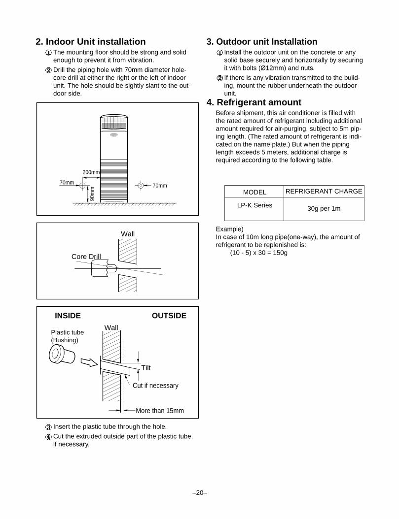
2. Indoor Unit installationThe mounting floor should be strong and solidenough to prevent it from vibration.
Drill the piping hole with 70mm diameter hole-core drill at either the right or the left of indoorunit. The hole should be sightly slant to the out-door side.
Insert the plastic tube through the hole.
Cut the extruded outside part of the plastic tube,if necessary.
3. Outdoor unit InstallationInstall the outdoor unit on the concrete or anysolid base securely and horizontally by securingit with bolts (Ø12mm) and nuts.
If there is any vibration transmitted to the build-ing, mount the rubber underneath the outdoorunit.
4. Refrigerant amountBefore shipment, this air conditioner is filled withthe rated amount of refrigerant including additionalamount required for air-purging, subject to 5m pip-ing length. (The rated amount of refrigerant is indi-cated on the name plate.) But when the pipinglength exceeds 5 meters, additional charge isrequired according to the following table.
Example)In case of 10m long pipe(one-way), the amount ofrefrigerant to be replenished is:
(10 - 5) x 30 = 150g
Wall
Core Drill
Tilt
Cut if necessary
More than 15mm
WallPlastic tube(Bushing)
INSIDE OUTSIDE
200mm
70mm 70mm
90m
m MODEL
LP-K Series
REFRIGERANT CHARGE
30g per 1m
–21–
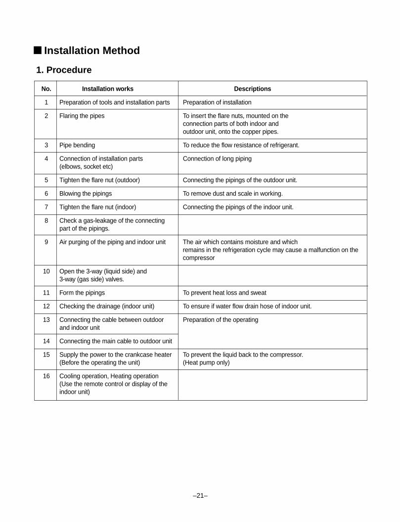
■ Installation Method
No. Installation works Descriptions
1 Preparation of tools and installation parts Preparation of installation
2 Flaring the pipes To insert the flare nuts, mounted on theconnection parts of both indoor andoutdoor unit, onto the copper pipes.
3 Pipe bending To reduce the flow resistance of refrigerant.
4 Connection of installation parts Connection of long piping(elbows, socket etc)
5 Tighten the flare nut (outdoor) Connecting the pipings of the outdoor unit.
6 Blowing the pipings To remove dust and scale in working.
7 Tighten the flare nut (indoor) Connecting the pipings of the indoor unit.
8 Check a gas-leakage of the connectingpart of the pipings.
9 Air purging of the piping and indoor unit The air which contains moisture and whichremains in the refrigeration cycle may cause a malfunction on thecompressor
10 Open the 3-way (liquid side) and3-way (gas side) valves.
11 Form the pipings To prevent heat loss and sweat
12 Checking the drainage (indoor unit) To ensure if water flow drain hose of indoor unit.
13 Connecting the cable between outdoor Preparation of the operatingand indoor unit
14 Connecting the main cable to outdoor unit
15 Supply the power to the crankcase heater To prevent the liquid back to the compressor.(Before the operating the unit) (Heat pump only)
16 Cooling operation, Heating operation(Use the remote control or display of theindoor unit)
1. Procedure
–22–
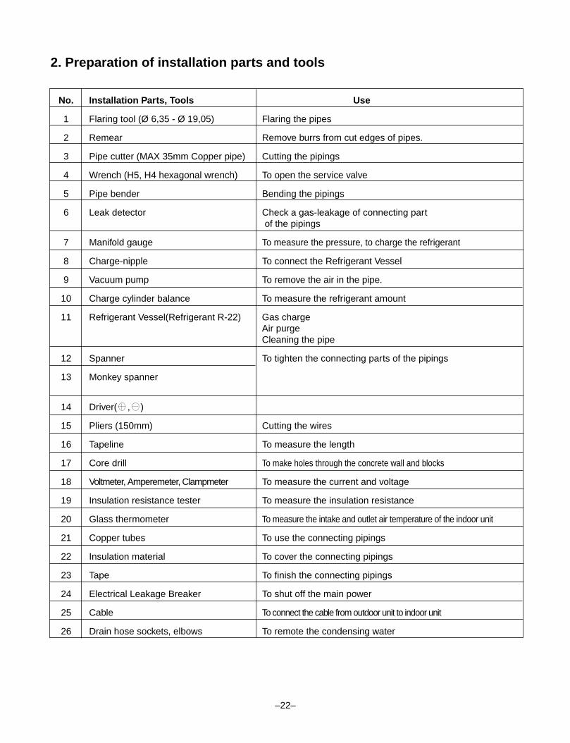
2. Preparation of installation parts and tools
No. Installation Parts, Tools Use
1 Flaring tool (Ø 6,35 - Ø 19,05) Flaring the pipes
2 Remear Remove burrs from cut edges of pipes.
3 Pipe cutter (MAX 35mm Copper pipe) Cutting the pipings
4 Wrench (H5, H4 hexagonal wrench) To open the service valve
5 Pipe bender Bending the pipings
6 Leak detector Check a gas-leakage of connecting partof the pipings
7 Manifold gauge To measure the pressure, to charge the refrigerant
8 Charge-nipple To connect the Refrigerant Vessel
9 Vacuum pump To remove the air in the pipe.
10 Charge cylinder balance To measure the refrigerant amount
11 Refrigerant Vessel(Refrigerant R-22) Gas chargeAir purgeCleaning the pipe
12 Spanner To tighten the connecting parts of the pipings
13 Monkey spanner
14 Driver( , )
15 Pliers (150mm) Cutting the wires
16 Tapeline To measure the length
17 Core drill To make holes through the concrete wall and blocks
18 Voltmeter, Amperemeter, Clampmeter To measure the current and voltage
19 Insulation resistance tester To measure the insulation resistance
20 Glass thermometer To measure the intake and outlet air temperature of the indoor unit
21 Copper tubes To use the connecting pipings
22 Insulation material To cover the connecting pipings
23 Tape To finish the connecting pipings
24 Electrical Leakage Breaker To shut off the main power
25 Cable To connect the cable from outdoor unit to indoor unit
26 Drain hose sockets, elbows To remote the condensing water
–23–
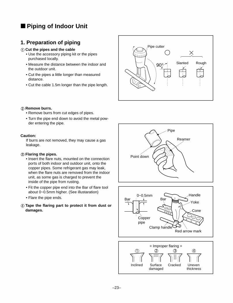
1. Preparation of pipingCut the pipes and the cable• Use the accessory piping kit or the pipes
purchased locally.
• Measure the distance between the indoor andthe outdoor unit.
• Cut the pipes a little longer than measureddistance.
• Cut the cable 1.5m longer than the pipe length.
Remove burrs.• Remove burrs from cut edges of pipes.
• Turn the pipe end down to avoid the metal pow-der entering the pipe.
Caution:If burrs are not removed, they may cause a gasleakage.
Flaring the pipes.• Insert the flare nuts, mounted on the connection
ports of both indoor and outdoor unit, onto thecopper pipes. Some refrigerant gas may leak,when the flare nuts are removed from the indoorunit, as some gas is charged to prevent theinside of the pipe from rusting.
• Fit the copper pipe end into the Bar of flare toolabout 0~0.5mm higher. (See illustaration)
• Flare the pipe ends.
Tape the flaring part to protect it from dust ordamages.
90°
Pipe cutter
Slanted Rough
Pipe
Point down
Reamer
Bar0~0.5mm
Copperpipe
Clamp handle
BarHandle
Yoke
Cone
Red arrow mark
4321= Improper flaring =
Inclined Cracked Surfacedamaged
Uneventhickness
■ Piping of Indoor Unit
–24–
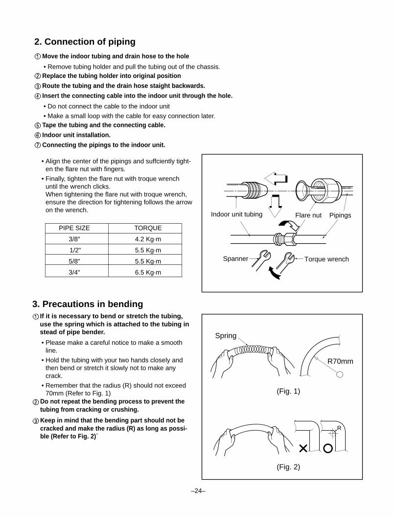
• Align the center of the pipings and suffciently tight-en the flare nut with fingers.
• Finally, tighten the flare nut with troque wrenchuntil the wrench clicks.When tightening the flare nut with troque wrench,ensure the direction for tightening follows the arrowon the wrench.
3. Precautions in bendingIf it is necessary to bend or stretch the tubing,use the spring which is attached to the tubing instead of pipe bender.
• Please make a careful notice to make a smoothline.
• Hold the tubing with your two hands closely andthen bend or stretch it slowly not to make anycrack.
• Remember that the radius (R) should not exceed70mm (Refer to Fig. 1)
Do not repeat the bending process to prevent thetubing from cracking or crushing.
Keep in mind that the bending part should not becracked and make the radius (R) as long as possi-ble (Refer to Fig. 2)`
PIPE SIZE TORQUE
3/8" 4.2 Kg.m
1/2" 5.5 Kg.m
5/8" 5.5 Kg.m
3/4" 6.5 Kg.m
Indoor unit tubing Flare nut Pipings
Torque wrenchSpanner
Spring
R70mm
(Fig. 1)
(Fig. 2)
R
2. Connection of piping
Move the indoor tubing and drain hose to the hole
• Remove tubing holder and pull the tubing out of the chassis.Replace the tubing holder into original position
Route the tubing and the drain hose staight backwards.
Insert the connecting cable into the indoor unit through the hole.
• Do not connect the cable to the indoor unit
• Make a small loop with the cable for easy connection later.Tape the tubing and the connecting cable.
Indoor unit installation.
Connecting the pipings to the indoor unit.
–25–
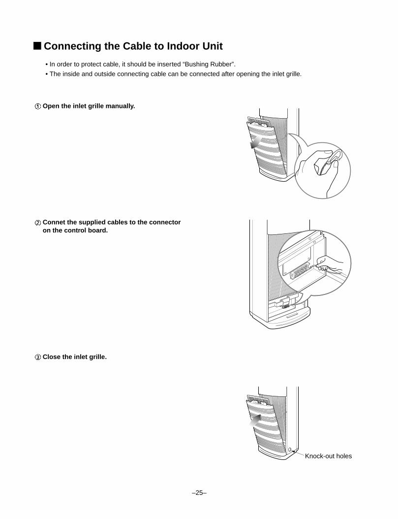
■ Connecting the Cable to Indoor Unit
• In order to protect cable, it should be inserted “Bushing Rubber”.
• The inside and outside connecting cable can be connected after opening the inlet grille.
Knock-out holes
Open the inlet grille manually.
Connet the supplied cables to the connectoron the control board.
Close the inlet grille.
28K/30K/40K
Gas side piping
Liquid side piping
Torque wrench
Outdoor unit
1 2 43 5 6
CLAMP(Ø10.7)
TO INDOOR UNIT CONNECTORPOWER SUPPLY
–26–
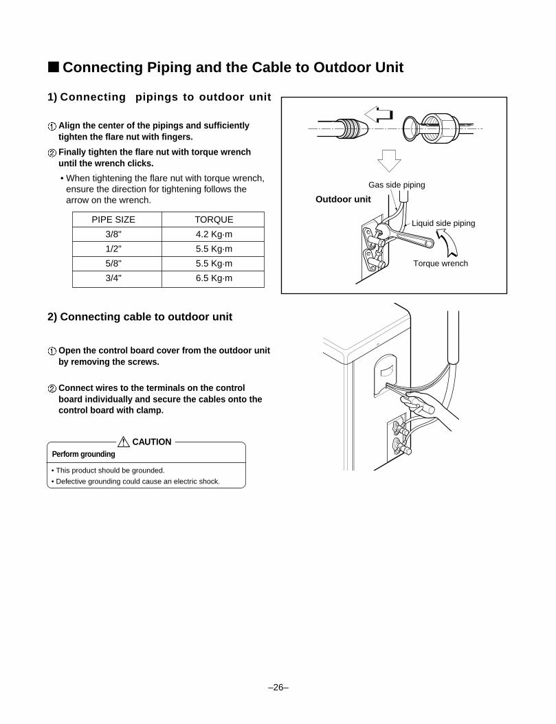
1) Connecting pipings to outdoor unit
Align the center of the pipings and sufficientlytighten the flare nut with fingers.
Finally tighten the flare nut with torque wrenchuntil the wrench clicks.
• When tightening the flare nut with torque wrench,ensure the direction for tightening follows thearrow on the wrench.
2) Connecting cable to outdoor unit
Open the control board cover from the outdoor unitby removing the screws.
Connect wires to the terminals on the controlboard individually and secure the cables onto thecontrol board with clamp.
■ Connecting Piping and the Cable to Outdoor Unit
PIPE SIZE TORQUE
3/8" 4.2 Kg.m
1/2" 5.5 Kg.m
5/8" 5.5 Kg.m
3/4" 6.5 Kg.m
Perform grounding
• This product should be grounded.
• Defective grounding could cause an electric shock.
CAUTION
–27–
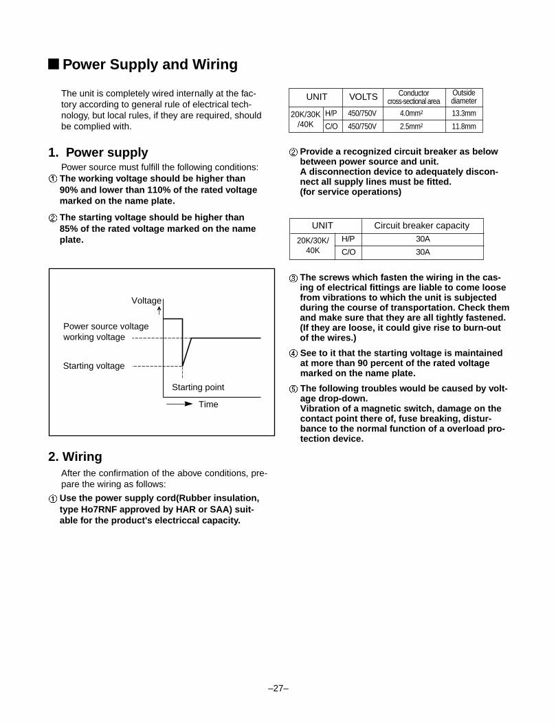
H/P 450/750V 4.0mm2 13.3mm
C/O 450/750V 2.5mm2 11.8mm
UNIT Circuit breaker capacity
Voltage
Time
Starting point
Power source voltageworking voltage
Starting voltage
The unit is completely wired internally at the fac-tory according to general rule of electrical tech-nology, but local rules, if they are required, shouldbe complied with.
1. Power supplyPower source must fulfill the following conditions:The working voltage should be higher than90% and lower than 110% of the rated voltagemarked on the name plate.
The starting voltage should be higher than85% of the rated voltage marked on the nameplate.
Provide a recognized circuit breaker as belowbetween power source and unit.A disconnection device to adequately discon-nect all supply lines must be fitted.(for service operations)
The screws which fasten the wiring in the cas-ing of electrical fittings are liable to come loosefrom vibrations to which the unit is subjectedduring the course of transportation. Check themand make sure that they are all tightly fastened.(If they are loose, it could give rise to burn-outof the wires.)
See to it that the starting voltage is maintainedat more than 90 percent of the rated voltagemarked on the name plate.
The following troubles would be caused by volt-age drop-down.Vibration of a magnetic switch, damage on thecontact point there of, fuse breaking, distur-bance to the normal function of a overload pro-tection device.
2. WiringAfter the confirmation of the above conditions, pre-pare the wiring as follows:
Use the power supply cord(Rubber insulation,type Ho7RNF approved by HAR or SAA) suit-able for the product's electriccal capacity.
■ Power Supply and Wiring
UNIT VOLTS Conductorcross-sectional area
Outsidediameter
H/P 30A
C/O 30A20K/30K/
40K
20K/30K/40K
–28–
■ Checking the Drainage and Form the Piping
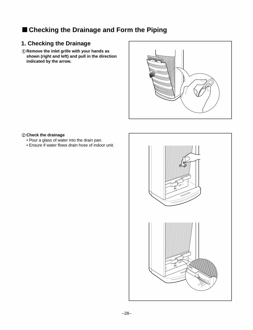
1. Checking the DrainageRemove the inlet grille with your hands asshown (right and left) and pull in the directionindicated by the arrow.
Check the drainage• Pour a glass of water into the drain pan.• Ensure if water flows drain hose of indoor unit.
–29–
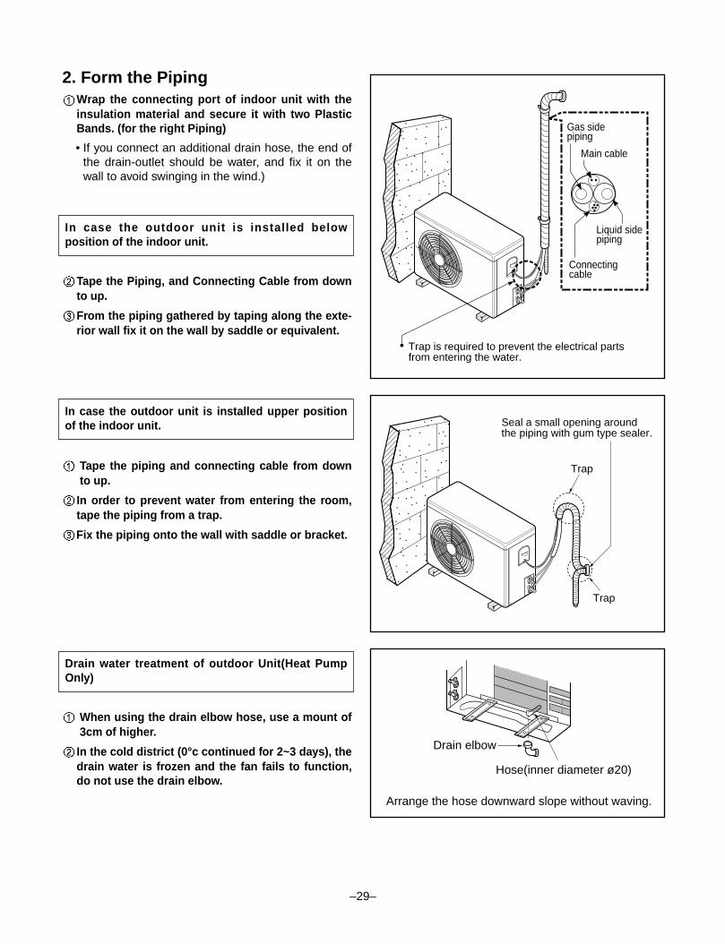
2. Form the PipingWrap the connecting port of indoor unit with theinsulation material and secure it with two PlasticBands. (for the right Piping)
• If you connect an additional drain hose, the end ofthe drain-outlet should be water, and fix it on thewall to avoid swinging in the wind.)
Tape the Piping, and Connecting Cable from downto up.
From the piping gathered by taping along the exte-rior wall fix it on the wall by saddle or equivalent.
Tape the piping and connecting cable from downto up.
In order to prevent water from entering the room,tape the piping from a trap.
Fix the piping onto the wall with saddle or bracket.
When using the drain elbow hose, use a mount of3cm of higher.
In the cold district (0°c continued for 2~3 days), thedrain water is frozen and the fan fails to function,do not use the drain elbow.
In case the outdoor unit is installed belowposition of the indoor unit.
In case the outdoor unit is installed upper positionof the indoor unit.
Drain water treatment of outdoor Unit(Heat PumpOnly)
������������
Trap
Trap
Seal a small opening aroundthe piping with gum type sealer.
Gas sidepiping
Main cable
Liquid sidepiping
Connectingcable
Trap is required to prevent the electrical partsfrom entering the water.
Drain elbow
Hose(inner diameter ø20)
Arrange the hose downward slope without waving.
–30–
1. PRECAUTIONS IN TEST RUN
• The initial power supply must provide at least 90% of the rated voltage.Otherwise, the air conditioner should not be operated.
Carry out the test run more than 5 minutes without fail.(Test run will be cancelled 18 minutes later automatically)
• The test run is started by pressing the down room temperature checking button and ON/OFF button for 3 sec-onds at the same time.
• To cancel the test run, press ON/OFF button.
• After completing work, be sure to measure and record trial run properties, and store measured data, etc.
• Measuring items are room temperature, outside temperature, suction temperature, blow out temperature, windvelocity, wind volume, voltage, current, presence of abnormal vibration and noise, operating pressure, pipingtemperature, compressive pressure.
• As to the structure and appearance, check following items.
2. Connection of power supply1. Connect the power supply cord to the independent power supply.
• Circuit breaker is required.
2. Operate the unit for fifteen minutes or more.
3. Evaluation of the performance1. Measure the temperature of the intake and discharge air.
2. Ensure the difference between the intake temperature and the discharge one is more than 8°C (Cooling) orreversely (Heating).
CHECK THE FOLLOWING ITEMS WHEN INSTALLATION IS COMPLETE
Caution
Is the circulation of air adequate?
Is the draining smooth?
Is the heat insulation complete(refrigerant and drain piping)?
Is there any leakage of refrigerant?
Is the remote controller switch operated?
Is there any faulty wiring?
Are not terminal screws loosened?
M4...118N.cm{12kgf.cm} M5...196N.cm{20kgf.cm}
M6...245N.cm{25kgf.cm} M8...588N.cm{60kgf.cm}
Test running
–31–
CAUTION
After the confirmation of the above conditions, prepare the wiring as follows:
1) Never fail to have an individual power specialized for the air conditioner. As for the method of wiring,be guided by the circuit diagram pasted on the inside of control box cover.
2) Provide a circuit breaker switch between power source and the unit.
3) The screw which fasten the wiring in the casing of electrical fittings are liable to come loose fromvibrations to which the unit is subjected during the course of transportation. Check them andmake sure that they are all tightly fastened. (If they are loose, it could give rise to burn-out of thewires.)
4) Specification of power source
5) Confirm that electrical capacity is sufficient.
6) Be sure that the starting voltage is maintained at more than 90 percent of the rated voltage markedon the name plate.
7) Confirm that the cable thickness is as specified in the power sources specification.(Particularly note the relation between cable length and thickness.)
8) Never fail to equip a leakage breaker where it is wet or moist.
9) The following troubles would be caused by voltage drop-down.
• Vibration of a magnetic switch, damage on the contact point there of, fuse breaking, disturbance to thenormal function of a overload protection device.
• Proper starting power is not given to the compressor.
Teach the customer the operation and maintenance procedures, using the operation manual (air filter cleaning,temperature control, etc.).
HAND OVER
3-way Valve
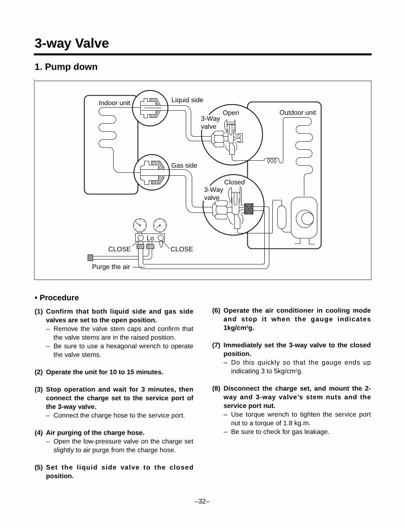
1. Pump down
• Procedure
(1) Confirm that both liquid side and gas sidevalves are set to the open position.– Remove the valve stem caps and confirm that
the valve stems are in the raised position.– Be sure to use a hexagonal wrench to operate
the valve stems.
(2) Operate the unit for 10 to 15 minutes.
(3) Stop operation and wait for 3 minutes, thenconnect the charge set to the service port ofthe 3-way valve.– Connect the charge hose to the service port.
(4) Air purging of the charge hose.– Open the low-pressure valve on the charge set
slightly to air purge from the charge hose.
(5) Set the liquid side valve to the closedposition.
(6) Operate the air conditioner in cooling modeand stop it when the gauge indicates1kg/cm2g.
(7) Immediately set the 3-way valve to the closedposition.– Do this quickly so that the gauge ends up
indicating 3 to 5kg/cm2g.
(8) Disconnect the charge set, and mount the 2-way and 3-way valve’s stem nuts and theservice port nut.– Use torque wrench to tighten the service port
nut to a torque of 1.8 kg.m.– Be sure to check for gas leakage.
Lo
Closed
Purge the air
Outdoor unit
Indoor unit Liquid side
Gas side
CLOSE
Open3-Wayvalve
3-Wayvalve
CLOSE
–32–
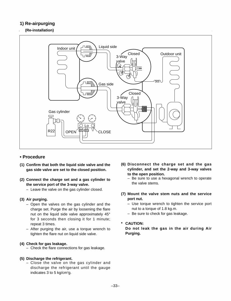
1) Re-airpurging(Re-installation)
• Procedure
(1) Confirm that both the liquid side valve and thegas side valve are set to the closed position.
(2) Connect the charge set and a gas cylinder tothe service port of the 3-way valve.– Leave the valve on the gas cylinder closed.
(3) Air purging.– Open the valves on the gas cylinder and the
charge set. Purge the air by loosening the flarenut on the liquid side valve approximately 45°for 3 seconds then closing it for 1 minute;repeat 3 times.
– After purging the air, use a torque wrench totighten the flare nut on liquid side valve.
(4) Check for gas leakage.– Check the flare connections for gas leakage.
(5) Discharge the refrigerant.– Close the valve on the gas cylinder and
discharge the refr igerant until the gaugeindicates 3 to 5 kg/cm2g.
(6) Disconnect the charge set and the gascylinder, and set the 2-way and 3-way valvesto the open position.– Be sure to use a hexagonal wrench to operate
the valve stems.
(7) Mount the valve stem nuts and the serviceport nut.– Use torque wrench to tighten the service port
nut to a torque of 1.8 kg.m.– Be sure to check for gas leakage.
* CAUTION:Do not leak the gas in the air during AirPurging.
Lo
Closed
OPEN
Closed
Gas cylinder
R22
Outdoor unit
Indoor unit Liquid side
Gas side
CLOSE
3-Wayvalve
3-Wayvalve
–33–
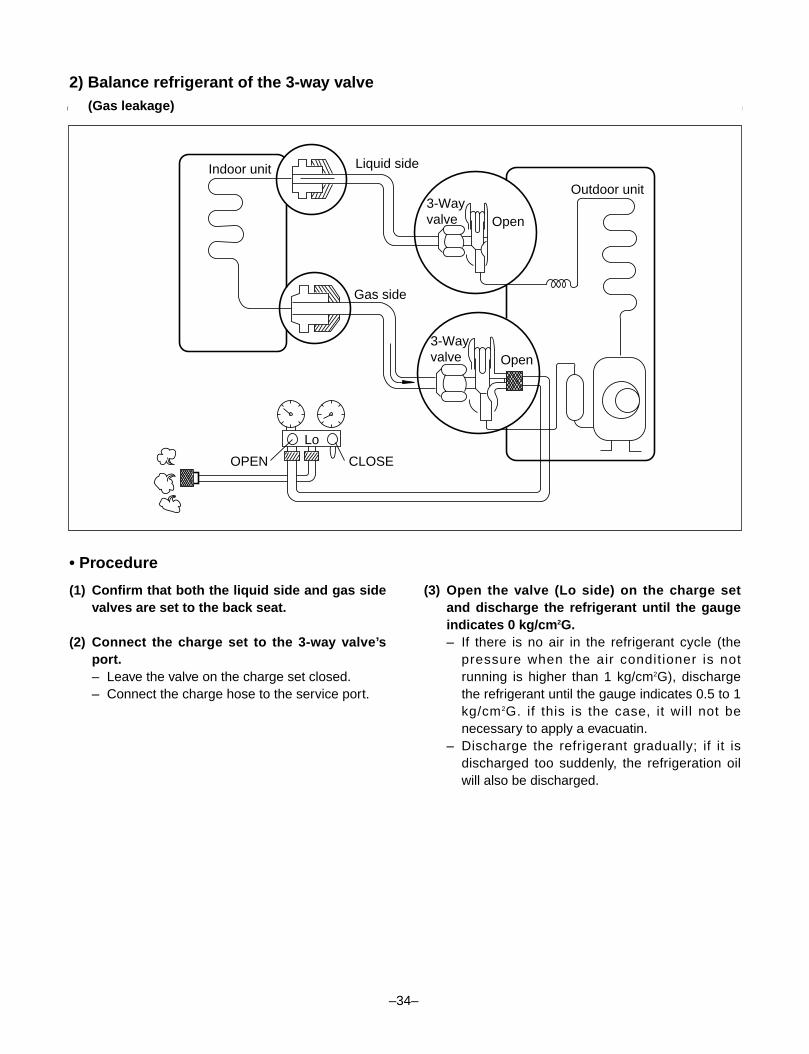
2) Balance refrigerant of the 3-way valve(Gas leakage)
• Procedure
(1) Confirm that both the liquid side and gas sidevalves are set to the back seat.
(2) Connect the charge set to the 3-way valve’sport.– Leave the valve on the charge set closed.– Connect the charge hose to the service port.
(3) Open the valve (Lo side) on the charge setand discharge the refrigerant until the gaugeindicates 0 kg/cm2G.– If there is no air in the refrigerant cycle (the
pressure when the air conditioner is notrunning is higher than 1 kg/cm2G), dischargethe refrigerant until the gauge indicates 0.5 to 1kg/cm2G. if this is the case, it will not benecessary to apply a evacuatin.
– Discharge the refrigerant gradually; if it isdischarged too suddenly, the refrigeration oilwill also be discharged.
Lo
Open
Open3-Wayvalve
3-Wayvalve
Gas side
CLOSEOPEN
Outdoor unit
Liquid sideIndoor unit
–34–
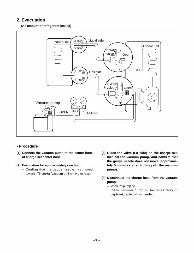
2. Evacuation(All amount of refrigerant leaked)
• Procedure
(1) Connect the vacuum pump to the center hoseof charge set center hose
(2) Evacuation for approximately one hour.– Confirm that the gauge needle has moved
toward -76 cmHg (vacuum of 4 mmHg or less).
(3) Close the valve (Lo side) on the charge set,turn off the vacuum pump, and confirm thatthe gauge needle does not move (approxima-tely 5 minutes after turning off the vacuumpump).
(4) Disconnect the charge hose from the vacuumpump.– Vacuum pump oil.
If the vacuum pump oil becomes dir ty ordepleted, replenish as needed.
Lo
Open
Open
Vacuum pump
3-Wayvalve
Outdoor unit
Liquid sideIndoor unit
Gas side
3-Wayvalve
CLOSEOPEN
–35–
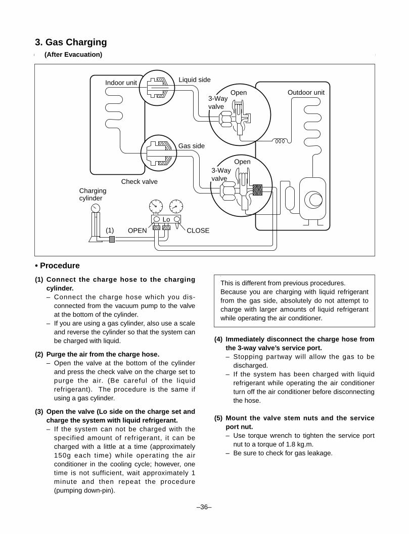
3. Gas Charging(After Evacuation)
• Procedure
(1) Connect the charge hose to the chargingcylinder.– Connect the charge hose which you dis-
connected from the vacuum pump to the valveat the bottom of the cylinder.
– If you are using a gas cylinder, also use a scaleand reverse the cylinder so that the system canbe charged with liquid.
(2) Purge the air from the charge hose.– Open the valve at the bottom of the cylinder
and press the check valve on the charge set topurge the air. (Be careful of the liquidrefrigerant). The procedure is the same ifusing a gas cylinder.
(3) Open the valve (Lo side on the charge set andcharge the system with liquid refrigerant.– If the system can not be charged with the
specified amount of refrigerant, it can becharged with a little at a time (approximately150g each time) while operating the airconditioner in the cooling cycle; however, onetime is not sufficient, wait approximately 1minute and then repeat the procedure(pumping down-pin).
(4) Immediately disconnect the charge hose fromthe 3-way valve’s service port.– Stopping partway will allow the gas to be
discharged.– If the system has been charged with liquid
refrigerant while operating the air conditionerturn off the air conditioner before disconnectingthe hose.
(5) Mount the valve stem nuts and the serviceport nut.– Use torque wrench to tighten the service port
nut to a torque of 1.8 kg.m.– Be sure to check for gas leakage.
\
This is different from previous procedures.Because you are charging with liquid refrigerantfrom the gas side, absolutely do not attempt tocharge with larger amounts of liquid refrigerantwhile operating the air conditioner.
Lo
Chargingcylinder
Outdoor unit
Indoor unit Liquid side
Gas side
CLOSE
Open3-Wayvalve
3-Wayvalve
OPEN
Open
Check valve
(1)
–36–
–37–
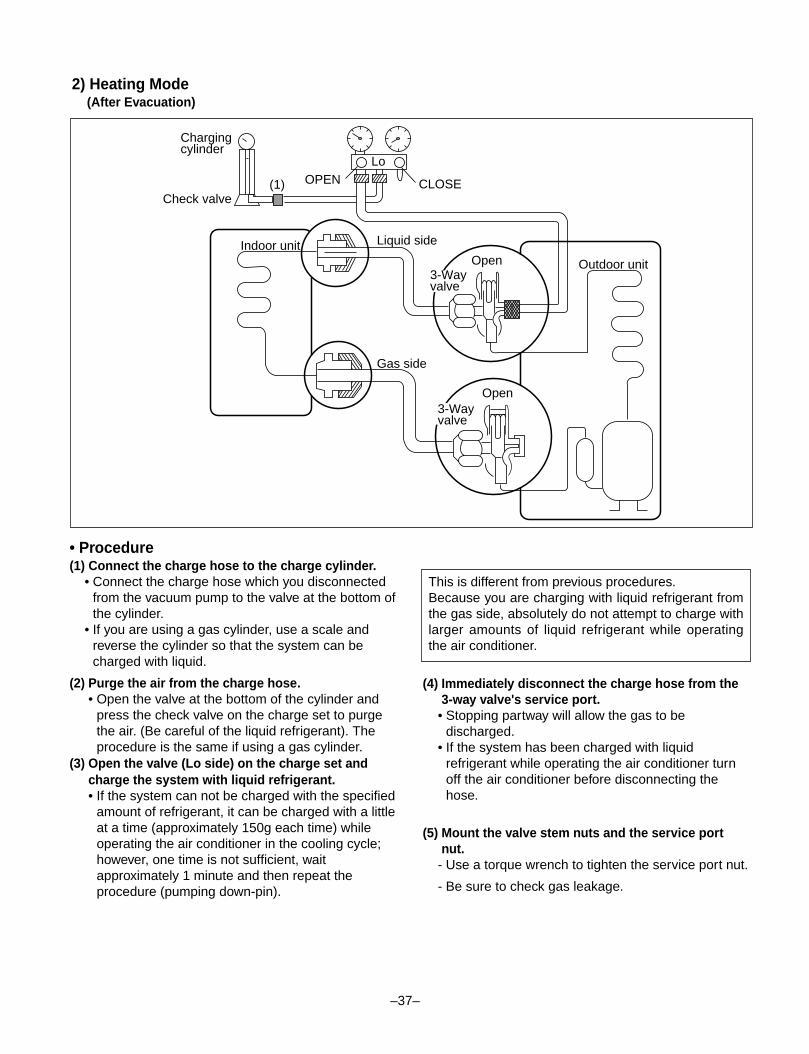
2) Heating Mode(After Evacuation)
CLOSE
LoOPEN(1)
Gas side
Liquid sideIndoor unit
Check valve
Chargingcylinder
Outdoor unitOpen
Open3-Wayvalve
3-Wayvalve
• Procedure(1) Connect the charge hose to the charge cylinder.
• Connect the charge hose which you disconnectedfrom the vacuum pump to the valve at the bottom ofthe cylinder.
• If you are using a gas cylinder, use a scale andreverse the cylinder so that the system can becharged with liquid.
(2) Purge the air from the charge hose.• Open the valve at the bottom of the cylinder and
press the check valve on the charge set to purgethe air. (Be careful of the liquid refrigerant). Theprocedure is the same if using a gas cylinder.
(3) Open the valve (Lo side) on the charge set andcharge the system with liquid refrigerant.• If the system can not be charged with the specified
amount of refrigerant, it can be charged with a littleat a time (approximately 150g each time) whileoperating the air conditioner in the cooling cycle;however, one time is not sufficient, waitapproximately 1 minute and then repeat theprocedure (pumping down-pin).
(4) Immediately disconnect the charge hose from the3-way valve's service port.
• Stopping partway will allow the gas to bedischarged.
• If the system has been charged with liquidrefrigerant while operating the air conditioner turnoff the air conditioner before disconnecting thehose.
(5) Mount the valve stem nuts and the service portnut.
- Use a torque wrench to tighten the service port nut.
- Be sure to check gas leakage.
This is different from previous procedures.Because you are charging with liquid refrigerant fromthe gas side, absolutely do not attempt to charge withlarger amounts of liquid refrigerant while operatingthe air conditioner.
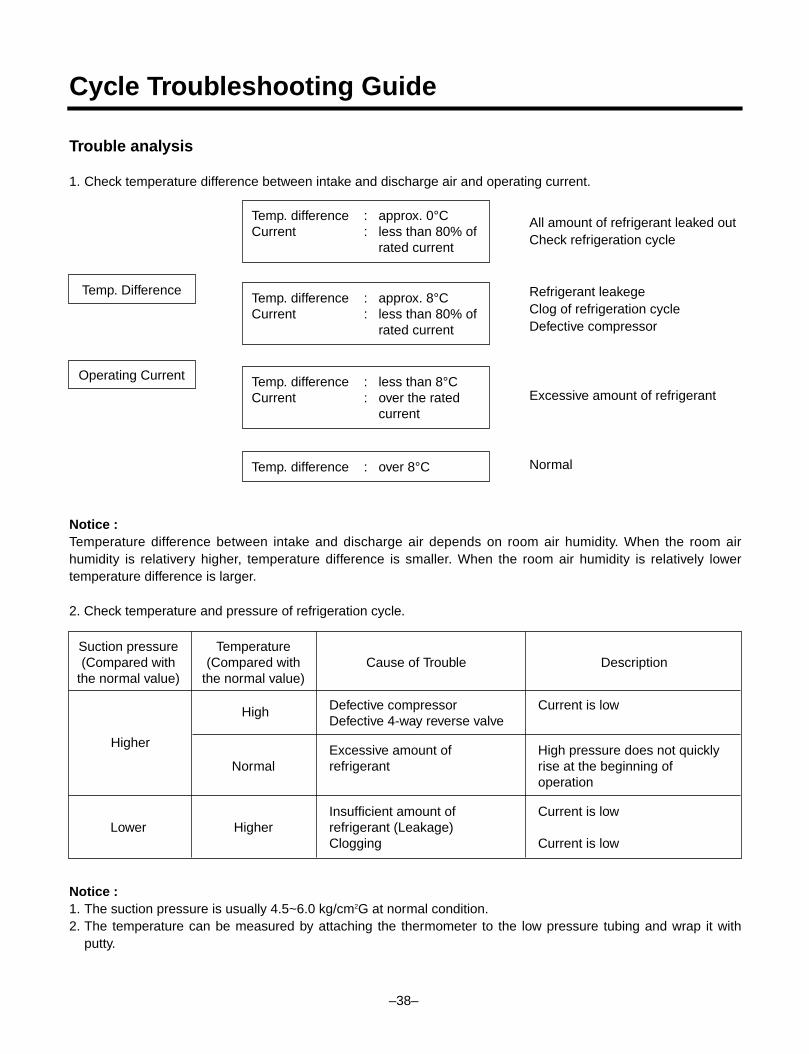
Cycle Troubleshooting Guide
Trouble analysis
1. Check temperature difference between intake and discharge air and operating current.
Temp. Difference
Temp. difference : approx. 0°CCurrent : less than 80% of
rated current
Temp. difference : approx. 8°CCurrent : less than 80% of
rated current
Temp. difference : less than 8°CCurrent : over the rated
current
Temp. difference : over 8°C
Operating Current
All amount of refrigerant leaked outCheck refrigeration cycle
Refrigerant leakegeClog of refrigeration cycleDefective compressor
Excessive amount of refrigerant
Normal
Notice :Temperature difference between intake and discharge air depends on room air humidity. When the room airhumidity is relativery higher, temperature difference is smaller. When the room air humidity is relatively lowertemperature difference is larger.
2. Check temperature and pressure of refrigeration cycle.
Notice :1. The suction pressure is usually 4.5~6.0 kg/cm2G at normal condition.2. The temperature can be measured by attaching the thermometer to the low pressure tubing and wrap it with
putty.
Suction pressure Temperature(Compared with (Compared with Cause of Trouble Description
the normal value) the normal value)
Defective compressor Current is lowDefective 4-way reverse valve
Excessive amount of High pressure does not quicklyNormal refrigerant rise at the beginning of
operation
Insufficient amount of Current is lowLower Higher refrigerant (Leakage)
Clogging Current is low
High
Higher
–38–
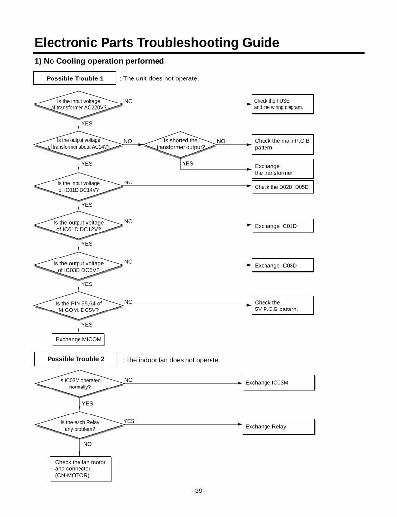
Electronic Parts Troubleshooting Guide1) No Cooling operation performed
: The unit does not operate.Possible Trouble 1
–39–
YES
YES
YES
NO
YES
Is the input voltageof transformer AC220V?
Is the input voltageof IC01D DC14V?
Check the FUSEand the wiring diagram.
Is the output voltage of IC01D DC12V?
Is the PIN 55,64 ofMICOM. DC5V?
Exchange MICOM
YES
NO Check the main P.C.Bpattern
NO
NO
Check the D02D~D05D
NO
YES Exchange the transformer
Is shorted thetransformer output?
NO
YES
Is the output voltage of IC03D DC5V?
NO
Exchange IC01D
Exchange IC03D
Is the output voltageof transformer about AC14V?
Check the 5V P.C.B pattern.
Possible Trouble 2 : The indoor fan does not operate.
NO
Is IC03M operatednormally?
Check the fan motorand connector.(CN-MOTOR)
YES
Is the each Relayany problem?
NO
YES
Exchange IC03M
Exchange Relay
–40–
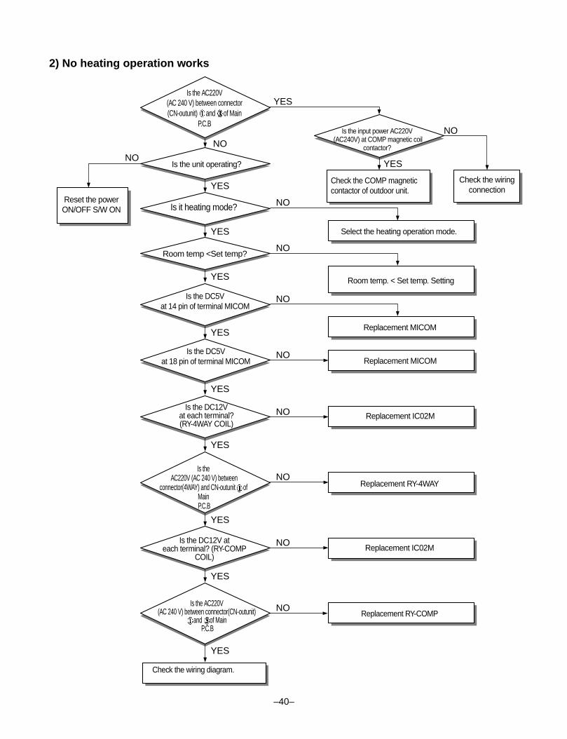
2) No heating operation works
YES
YES
NO
NO
NO
NO
NO
NO
NO
NO
NONO
NO
YES
YES
YES
YES
YES
YES
YES
YES
YES
Reset the powerON/OFF S/W ON
Is the AC220V(AC 240 V) between connector(CN-outunit) and of Main
P.C.BIs the input power AC220V
(AC240V) at COMP magnetic coilcontactor?
Is it heating mode?
Room temp <Set temp?
Is the DC5Vat 14 pin of terminal MICOM
Is the DC5Vat 18 pin of terminal MICOM
Is the DC12Vat each terminal?(RY-4WAY COIL)
Is theAC220V (AC 240 V) between
connector(4WAY) and CN-outunit ofMainP.C.B
Is the DC12V ateach terminal? (RY-COMP
COIL)
Replacement RY-4WAY
Replacement IC02M
Replacement RY-COMPIs the AC220V
(AC 240 V) between connector(CN-outunit)and of Main
P.C.B
Check the wiring diagram.
Replacement MICOM
Replacement IC02M
Room temp. < Set temp. Setting
Replacement MICOM
Select the heating operation mode.
Check the COMP magneticcontactor of outdoor unit.
Check the wiringconnection
Is the unit operating?
–41–
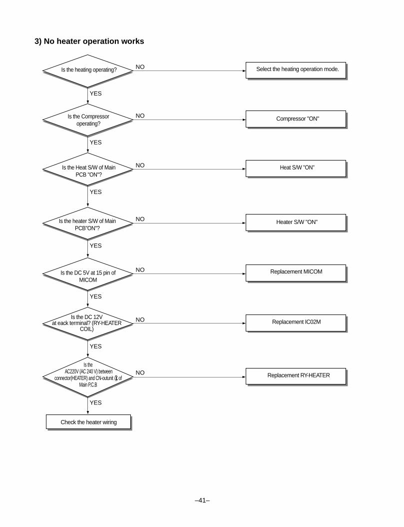
3) No heater operation works
YES
NO
YES
NO
YES
NO
YES
NO
YES
NO
YES
NO
YES
NO
Is the heating operating?
Is the Compressoroperating?
Is the Heat S/W of MainPCB "ON"?
Heat S/W "ON"
Heater S/W "ON"
Replacement MICOM
Replacement IC02M
Replacement RY-HEATER
Is the heater S/W of MainPCB"ON"?
Is the DC 5V at 15 pin ofMICOM
Is the DC 12Vat eack terminal? (RY-HEATER
COIL)
Is theAC220V (AC 240 V) between
connector(HEATER) and CN-outunit ofMain P.C.B
Check the heater wiring
Select the heating operation mode.
Compressor "ON"
–42–
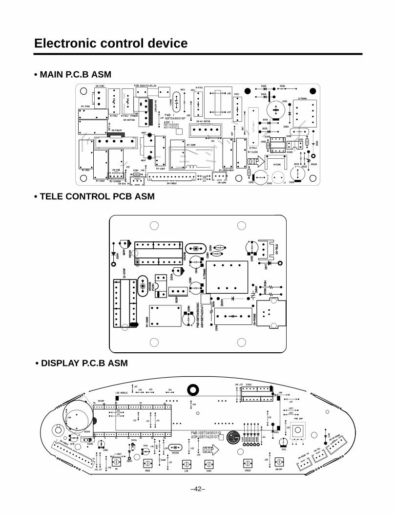
Electronic control device
• MAIN P.C.B ASM
• TELE CONTROL PCB ASM
• DISPLAY P.C.B ASM
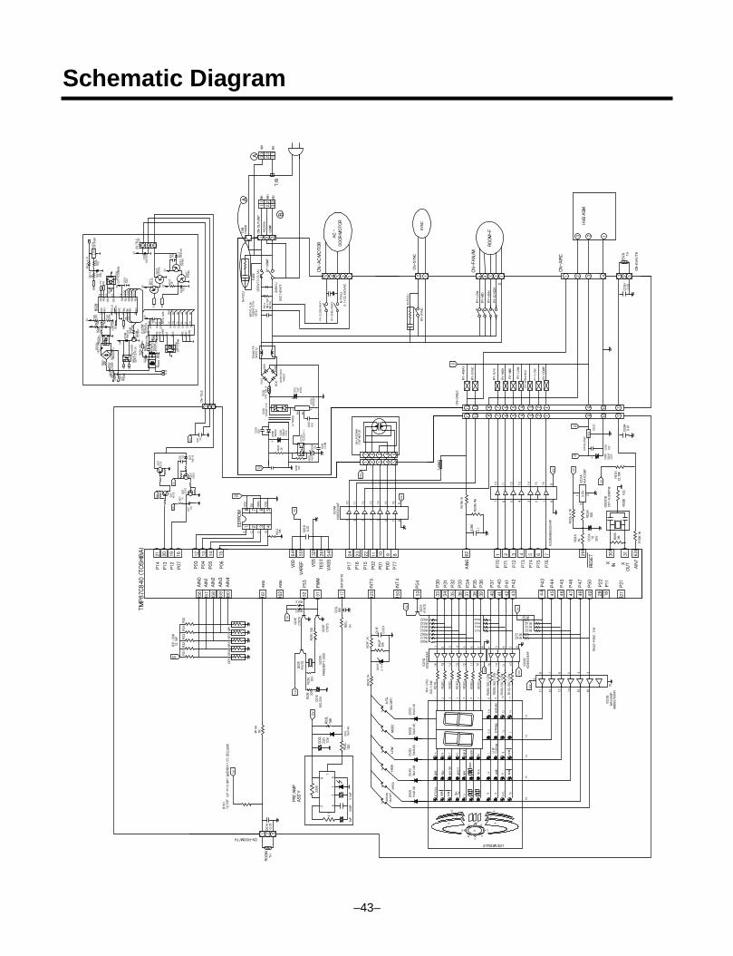
Schematic Diagram
–43–
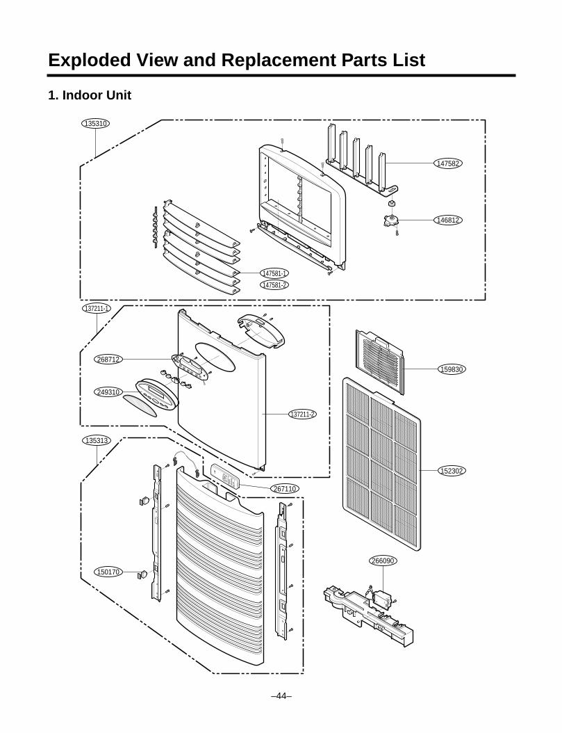
Exploded View and Replacement Parts List
1. Indoor Unit
–44–
135310
147581-1
147581-2
147582
146812
137211-1
135313
137211-2
266090
152302
159830
267110
249310
150170
268712
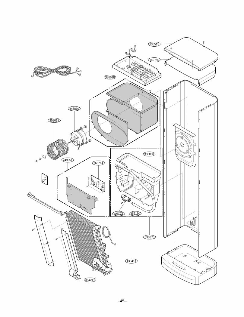
–45–
149750
135515
336610
359011
346810
249951268714
354211
130411
330870
W0CZZ 352150
330860
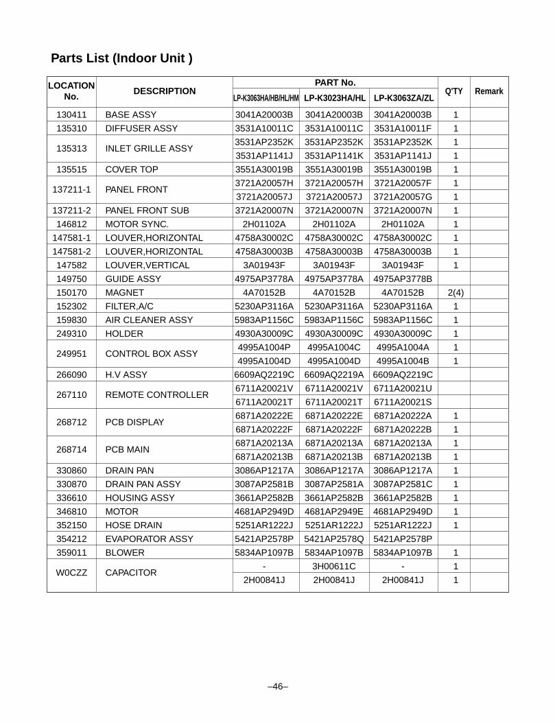
PART No.Q'TY Remark
130411 BASE ASSY 3041A20003B 3041A20003B 3041A20003B 1
135310 DIFFUSER ASSY 3531A10011C 3531A10011C 3531A10011F 1
135313 INLET GRILLE ASSY3531AP2352K 3531AP2352K 3531AP2352K 1
3531AP1141J 3531AP1141K 3531AP1141J 1
135515 COVER TOP 3551A30019B 3551A30019B 3551A30019B 1
137211-1 PANEL FRONT3721A20057H 3721A20057H 3721A20057F 1
3721A20057J 3721A20057J 3721A20057G 1
137211-2 PANEL FRONT SUB 3721A20007N 3721A20007N 3721A20007N 1
146812 MOTOR SYNC. 2H01102A 2H01102A 2H01102A 1
147581-1 LOUVER,HORIZONTAL 4758A30002C 4758A30002C 4758A30002C 1
147581-2 LOUVER,HORIZONTAL 4758A30003B 4758A30003B 4758A30003B 1
147582 LOUVER,VERTICAL 3A01943F 3A01943F 3A01943F 1
149750 GUIDE ASSY 4975AP3778A 4975AP3778A 4975AP3778B
150170 MAGNET 4A70152B 4A70152B 4A70152B 2(4)
152302 FILTER,A/C 5230AP3116A 5230AP3116A 5230AP3116A 1
159830 AIR CLEANER ASSY 5983AP1156C 5983AP1156C 5983AP1156C 1
249310 HOLDER 4930A30009C 4930A30009C 4930A30009C 1
249951 CONTROL BOX ASSY4995A1004P 4995A1004C 4995A1004A 1
4995A1004D 4995A1004D 4995A1004B 1
266090 H.V ASSY 6609AQ2219C 6609AQ2219A 6609AQ2219C
267110 REMOTE CONTROLLER6711A20021V 6711A20021V 6711A20021U
6711A20021T 6711A20021T 6711A20021S
268712 PCB DISPLAY6871A20222E 6871A20222E 6871A20222A 1
6871A20222F 6871A20222F 6871A20222B 1
268714 PCB MAIN6871A20213A 6871A20213A 6871A20213A 1
6871A20213B 6871A20213B 6871A20213B 1
330860 DRAIN PAN 3086AP1217A 3086AP1217A 3086AP1217A 1
330870 DRAIN PAN ASSY 3087AP2581B 3087AP2581A 3087AP2581C 1
336610 HOUSING ASSY 3661AP2582B 3661AP2582B 3661AP2582B 1
346810 MOTOR 4681AP2949D 4681AP2949E 4681AP2949D 1
352150 HOSE DRAIN 5251AR1222J 5251AR1222J 5251AR1222J 1
354212 EVAPORATOR ASSY 5421AP2578P 5421AP2578Q 5421AP2578P
359011 BLOWER 5834AP1097B 5834AP1097B 5834AP1097B 1
W0CZZ CAPACITOR- 3H00611C - 1
2H00841J 2H00841J 2H00841J 1
Parts List (Indoor Unit )
–46–
LP-K3063HA/HB/HL/HM LP-K3023HA/HL LP-K3063ZA/ZLLOCATION
No.DESCRIPTION
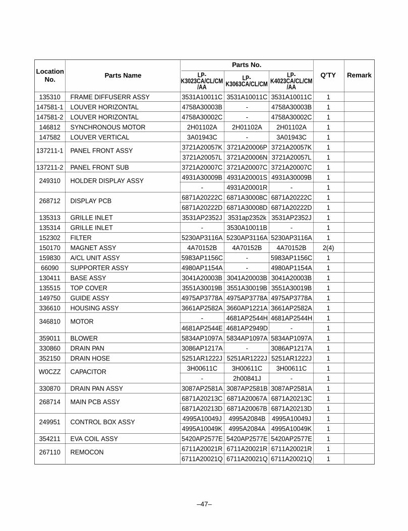
–47–
135310 FRAME DIFFUSERR ASSY 3531A10011C 3531A10011C 3531A10011C 1
147581-1 LOUVER HORIZONTAL 4758A30003B - 4758A30003B 1
147581-2 LOUVER HORIZONTAL 4758A30002C - 4758A30002C 1
146812 SYNCHRONOUS MOTOR 2H01102A 2H01102A 2H01102A 1
147582 LOUVER VERTICAL 3A01943C - 3A01943C 1
137211-1 PANEL FRONT ASSY 3721A20057K 3721A20006P 3721A20057K 1
3721A20057L 3721A20006N 3721A20057L 1
137211-2 PANEL FRONT SUB 3721A20007C 3721A20007C 3721A20007C 1
249310 HOLDER DISPLAY ASSY 4931A30009B 4931A20001S 4931A30009B 1
- 4931A20001R - 1
268712 DISPLAY PCB 6871A20222C 6871A30008C 6871A20222C 1
6871A20222D 6871A30008D 6871A20222D 1
135313 GRILLE INLET 3531AP2352J 3531ap2352k 3531AP2352J 1
135314 GRILLE INLET - 3530A10011B - 1
152302 FILTER 5230AP3116A 5230AP3116A 5230AP3116A 1
150170 MAGNET ASSY 4A70152B 4A70152B 4A70152B 2(4)
159830 A/CL UNIT ASSY 5983AP1156C - 5983AP1156C 1
66090 SUPPORTER ASSY 4980AP1154A - 4980AP1154A 1
130411 BASE ASSY 3041A20003B 3041A20003B 3041A20003B 1
135515 TOP COVER 3551A30019B 3551A30019B 3551A30019B 1
149750 GUIDE ASSY 4975AP3778A 4975AP3778A 4975AP3778A 1
336610 HOUSING ASSY 3661AP2582A 3660AP1221A 3661AP2582A 1
346810 MOTOR - 4681AP2544H 4681AP2544H 1
4681AP2544E 4681AP2949D - 1
359011 BLOWER 5834AP1097A 5834AP1097A 5834AP1097A 1
330860 DRAIN PAN 3086AP1217A - 3086AP1217A 1
352150 DRAIN HOSE 5251AR1222J 5251AR1222J 5251AR1222J 1
W0CZZ CAPACITOR 3H00611C 3H00611C 3H00611C 1
- 2h00841J - 1
330870 DRAIN PAN ASSY 3087AP2581A 3087AP2581B 3087AP2581A 1
268714 MAIN PCB ASSY 6871A20213C 6871A20067A 6871A20213C 1
6871A20213D 6871A20067B 6871A20213D 1
249951 CONTROL BOX ASSY 4995A10049J 4995A2084B 4995A10049J 1
4995A10049K 4995A2084A 4995A10049K 1
354211 EVA COIL ASSY 5420AP2577E 5420AP2577E 5420AP2577E 1
267110 REMOCON 6711A20021R 6711A20021R 6711A20021R 1
6711A20021Q 6711A20021Q 6711A20021Q 1
LocationNo.
Parts Name
Parts No.
LP-K3023CA/CL/CM
/AALP-
K3063CA/CL/CMLP-
K4023CA/CL/CM/AA
Q'TY Remark
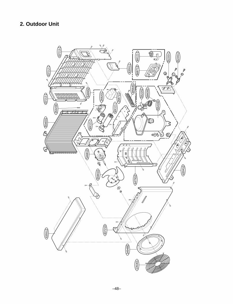
2. Outdoor Unit
–48–
CS R
4355
12
4372
10
3494
80
4479
105590
10
5468
10W
0CZZ
-2
W0C
ZZ-1
2687
11
W66
40
2692
01
6499
50
5540
3143
7213
-1
2632
30
4372
12-1
4372
13-2
4355
11
6687
13W
0CZZ
-3
5522
03-1
5522
03-2
5522
02
5660
00
5541
60
4304
10
1353
01
–49–
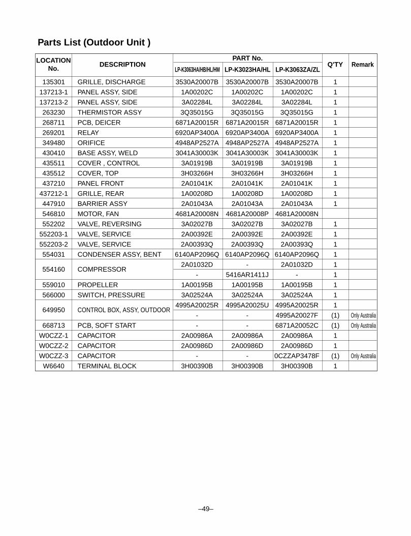
Parts List (Outdoor Unit )
PART No.Q'TY Remark
135301 GRILLE, DISCHARGE 3530A20007B 3530A20007B 3530A20007B 1
137213-1 PANEL ASSY, SIDE 1A00202C 1A00202C 1A00202C 1
137213-2 PANEL ASSY, SIDE 3A02284L 3A02284L 3A02284L 1
263230 THERMISTOR ASSY 3Q35015G 3Q35015G 3Q35015G 1
268711 PCB, DEICER 6871A20015R 6871A20015R 6871A20015R 1
269201 RELAY 6920AP3400A 6920AP3400A 6920AP3400A 1
349480 ORIFICE 4948AP2527A 4948AP2527A 4948AP2527A 1
430410 BASE ASSY, WELD 3041A30003K 3041A30003K 3041A30003K 1
435511 COVER , CONTROL 3A01919B 3A01919B 3A01919B 1
435512 COVER, TOP 3H03266H 3H03266H 3H03266H 1
437210 PANEL FRONT 2A01041K 2A01041K 2A01041K 1
437212-1 GRILLE, REAR 1A00208D 1A00208D 1A00208D 1
447910 BARRIER ASSY 2A01043A 2A01043A 2A01043A 1
546810 MOTOR, FAN 4681A20008N 4681A20008P 4681A20008N
552202 VALVE, REVERSING 3A02027B 3A02027B 3A02027B 1
552203-1 VALVE, SERVICE 2A00392E 2A00392E 2A00392E 1
552203-2 VALVE, SERVICE 2A00393Q 2A00393Q 2A00393Q 1
554031 CONDENSER ASSY, BENT 6140AP2096Q 6140AP2096Q 6140AP2096Q 1
554160 COMPRESSOR2A01032D - 2A01032D 1
- 5416AR1411J - 1
559010 PROPELLER 1A00195B 1A00195B 1A00195B 1
566000 SWITCH, PRESSURE 3A02524A 3A02524A 3A02524A 1
649950 CONTROL BOX, ASSY, OUTDOOR4995A20025R 4995A20025U 4995A20025R 1
- - 4995A20027F (1) Only Australia
668713 PCB, SOFT START - - 6871A20052C (1) Only Australia
W0CZZ-1 CAPACITOR 2A00986A 2A00986A 2A00986A 1
W0CZZ-2 CAPACITOR 2A00986D 2A00986D 2A00986D 1
W0CZZ-3 CAPACITOR - - 0CZZAP3478F (1) Only Australia
W6640 TERMINAL BLOCK 3H00390B 3H00390B 3H00390B 1
LP-K3063HA/HB/HL/HM LP-K3023HA/HL LP-K3063ZA/ZLLOCATION
No.DESCRIPTION
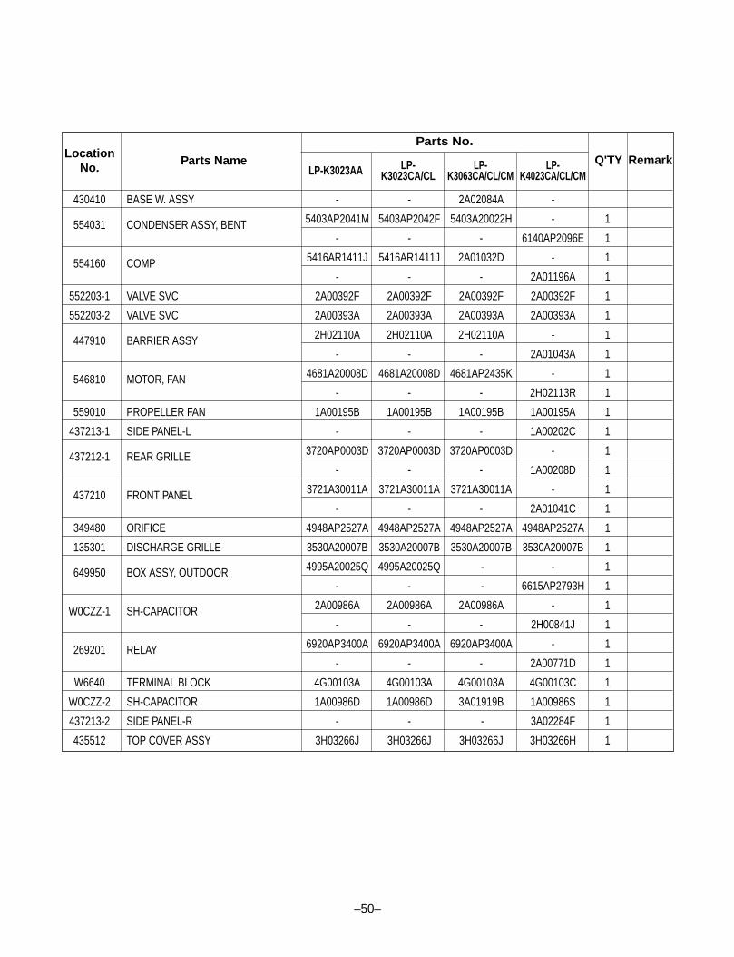
–50–
430410 BASE W. ASSY - - 2A02084A -
554031 CONDENSER ASSY, BENT 5403AP2041M 5403AP2042F 5403A20022H - 1
- - - 6140AP2096E 1
554160 COMP 5416AR1411J 5416AR1411J 2A01032D - 1
- - - 2A01196A 1
552203-1 VALVE SVC 2A00392F 2A00392F 2A00392F 2A00392F 1
552203-2 VALVE SVC 2A00393A 2A00393A 2A00393A 2A00393A 1
447910 BARRIER ASSY 2H02110A 2H02110A 2H02110A - 1
- - - 2A01043A 1
546810 MOTOR, FAN 4681A20008D 4681A20008D 4681AP2435K - 1
- - - 2H02113R 1
559010 PROPELLER FAN 1A00195B 1A00195B 1A00195B 1A00195A 1
437213-1 SIDE PANEL-L - - - 1A00202C 1
437212-1 REAR GRILLE 3720AP0003D 3720AP0003D 3720AP0003D - 1
- - - 1A00208D 1
437210 FRONT PANEL 3721A30011A 3721A30011A 3721A30011A - 1
- - - 2A01041C 1
349480 ORIFICE 4948AP2527A 4948AP2527A 4948AP2527A 4948AP2527A 1
135301 DISCHARGE GRILLE 3530A20007B 3530A20007B 3530A20007B 3530A20007B 1
649950 BOX ASSY, OUTDOOR 4995A20025Q 4995A20025Q - - 1
- - - 6615AP2793H 1
W0CZZ-1 SH-CAPACITOR 2A00986A 2A00986A 2A00986A - 1
- - - 2H00841J 1
269201 RELAY 6920AP3400A 6920AP3400A 6920AP3400A - 1
- - - 2A00771D 1
W6640 TERMINAL BLOCK 4G00103A 4G00103A 4G00103A 4G00103C 1
W0CZZ-2 SH-CAPACITOR 1A00986D 1A00986D 3A01919B 1A00986S 1
437213-2 SIDE PANEL-R - - - 3A02284F 1
435512 TOP COVER ASSY 3H03266J 3H03266J 3H03266J 3H03266H 1
LocationNo.
Parts Name
Parts No.
LP-K3023AA LP-K3023CA/CL
LP-K3063CA/CL/CM
LP-K4023CA/CL/CM
Q'TY Remark

P/No.: 3828A20156A
November, 2001
Printed in Korea