Embed Size (px)
Citation preview

SALEEN SPEEDLAB SERIES VI
STANDARD SC UPGRADE KIT
INSTALLATION MANUAL: 2005 MUSTANG 4.6 3V MANUAL P/N: 10-8002-C14338C
SUPERCHARGER KIT P/N: 10-1607-B14083*
Saleen Performance, Inc. 1225 East Maple Rd. , MI 48083 248-743-4800 www.saleen.com

1

2
DO NOT INSTALL ANY AFTERMARKET CHIPS OR PROGRAMMERS, OR HAVE YOUR PCM REPROGRAMMED ANYWHERE BUT AT SALEEN FOR THIS SUPERCHARGER KIT. THE 2005 MUSTANG USES AN ELECTRONIC THROTTLE CONTROL (ETC), WHICH IS CONTROLLED BY THE POWERTRAIN CONTROL MODULE (PCM) AND THE CALIBRATION INSIDE. AFTERMARKET CHIPS DO NOT PROPERLY RECALIBRATE THE ENGINE MANAGEMENT SYSTEM; THIS CREATES A DANGEROUS SITUATION THAT COULD RESULT IN A STUCK THROTTLE AND CAN LEAD TO INJURY OR DEATH. SALEEN FULLY REPROGRAMS THE PCM TO FORD STANDARDS, AND ENSURES THAT ALL ENGINE SAFETY CONTROLS ARE FULLY FUNCTIONAL.

3
THE SALEEN SERIES VI SUPERCHARGER AND ACCOMPANYING PROGRAMMING ARE DESIGNED
AROUND THE USE OF 91 OCTANE FUEL OR HIGHER ONLY. BEFORE YOU RUN YOUR
MUSTANG WITH THE SERIES VI KIT INSTALLED EVEN ONCE, YOU MUST EITHER DRAIN THE
FUEL TANK COMPLETELY AND FILL IT UP WITH 91 OCTANE, OR BEGIN USING 91 OCTANE IN YOUR
MUSTANG TWO COMPLETE FILLUPS BEFORE INSTALLATION.

4
IF YOU ARE NOT EXPERIENCED IN THE AREA OF AUTOMOTIVE MECHANICS, WE STRONGLY URGE THAT YOU REFER THIS INSTALLATION TO A CERTIFIED INSTALLER OR TECHNICIAN

5
Saleen Speedlab Series VI Supercharger Upgrade Kit Installation Guide for 2005-07 Mustang 4.6 3V
WELCOME! Thank you for buying the Upgrade Kit for Saleen’s Series VI Supercharger for the 2005-07 Mustang with the 4.6-liter, 3-valve motor. We appreciate your business, and we hope you enjoy your product. For your benefit, please read the following instructions completely and thoroughly before attempting to install the supercharger upgrade kit. Many questions we have received from customers about the installation of our products could have been easily solved by information listed in the accompanying installation guide. We want you to enjoy the product in its fully functional state, and reading this tutorial is a great first step to transforming the ferocious supercharged Mustang or S281 into an even more formidable road car. PLEASE NOTE THAT IF YOU HAVE ANY AFTERMARKET PARTS ALREADY INSTALLED ON YOUR MUSTANG, YOU MUST RETURN THE CAR TO STOCK S281 SUPERCHARGED STATUS – THIS INCLUDES PULLEYS, CHIPS, PROGRAMMERS, ETC. THE CAR WILL NOT FUNCTION AND PARTS MAY NOT FIT PROPERLY IF OTHER AFTERMARKET PARTS ARE INSTALLED. SALEEN RECOMMENDS OBTAINING HTO SPARK PLUGS FOR THE SUPERCHARGER KITS WITH OUTPUTS OF 475HP AND HIGHER. THEY CAN BE OBTAINED FROM SALEEN: THE PART NUMBER IS 00-1601-C13394*. With at least one read of this installation guide under your belt before you begin your installation, you should be well on your way to one hot Mustang! FINALLY, BE SURE THAT YOU FILL OUT THE PROCESSOR QUESTIONAIRE AND RETURN IT TO SALEEN WITH YOUR PCM! WE CANNOT FLASH THE PCM WITHOUT THAT QUESTIONAIRE! Again, thank you for choosing Saleen!

6
Obtain the following parts:
Part Number Description Qty. 00-1701-C12076* Fuel Injector, S281E 8 06-1602-C13093A Air Box Cover S281E 1 06-1607-C12395A 475 HP pulley 1 10-1602-B14619* AIR INLET DUCT ASSY, SER VI HIGH HP KITS,
2005-07 MUSTANG 1
00-9001-C13829* MACHINE SCREW M4x0.7x6 Zn 2
OBTAIN THE FOLLOWING TOOLS: • ½ ” DRIVE BREAKER BAR • FUEL LINE DISCONNECT TOOL • 3/8” DRIVE, 15MM SOCKET • DUCT TAPE • PANEL PULLER • ½ " DRIVE IMPACT GUN • ½ " DRIVE 24MM IMPACT
SOCKET • ½ ” DRIVE BREAKER BAR • 3/8” DRIVE RATCHET • 3/8” DRIVE 13MM DEEP SOCKET • 3/8” DRIVE FT.-LB. TORQUE
WRENCH • ¼ ” DRIVE RATCHET • ¼ ” DRIVE 10MM DEEP SOCKET • ¼ ” DRIVE INCH-POUND
TORQUE WRENCH • RED LOCTITE • HOSE CLAMP PLIERS

7
Figure 1
Figure 2
Figure 3
Figure 4
Bolt
Grey tabs
i Removing the Processor
1. You must remove the processor and send it to Saleen so that the processor can be reprogrammed. Your car will run poorly with the supercharger installed if the processor is not properly reprogrammed.
2. With an 8mm wrench, disconnect the battery ground terminal. (FIGURE 1)
3. Disconnect the battery positive terminal. (FIGURE 2)
4. Find the PCM; it is located adjacent to the black fuse box, and just a few inches from the rear outboard corner of the front shroud on the passenger side.
5. Grab the grey tabs that hold the multi-pin connectors onto the PCM. Lift the grey tabs toward the front of the car until the wire connectors pop out of place (FIGURE 3).
6. Using a 10mm socket with 1/4” drive ratchet, remove the two processor mounting bolts (one at the top of the bracket, one at the bottom).
7. Pull the processor towards the front of the car and wiggle it out of the bracket. (FIGURE 4).
8. Fill out the questionnaire on the following page, and send the questionnaire in with the processor to Saleen, attention PCM Programming. Our address is on the cover page of this manual.


9
ORDER OF OPERATIONS: (NOTE: REMOVE ALL ENGINE-RELATED AFTERMARKET PARTS FROM CAR, INCLUDING CHIPS AND PULLEYS, AS THEY WILL INTERFERE WITH FIT AND OPERATION OF THIS KIT).
1 Remove the mass airflow sensor connector from the air cleaner cover, as shown in FIGURE 1.
2 Remove air cleaner cover from filter box by pulling the two rear clips towards the front of the car. (FIGURE 2)
3 Remove the crankcase vent tube from the air cleaner outlet pipe. (FIGURE 3)
Figure 3
Figure 1
Figure 2

10
Figure 4
4 Loosen clamp connecting the air cleaner outlet pipe to the throttle body and remove the air cleaner outlet pipe. This will be replaced by the Saleen air inlet tube. (FIGURE 4)
5 Detach the 2 wiring harness retainers from the passenger side fuel rail stud bolts and position the harness aside. (FIGURE 5)
6 Using a panel puller, remove the vacuum tube retainer from the driver side rear fuel rail stud.
7 Disconnect the fuel rail pressure and temperature sensor electrical connector and vacuum hose. (FIGURE 6)
Figure 5
Figure 6

11
Figure 7
Figure 9
Figure 8
8 Disconnect the 8 fuel injector electrical connectors. (FIGURE 7)
9 Remove the fuel line safety clip from the fuel line.
10 Place a rag over the fuel line connection.
11 AT THIS TIME YOU MUST NOT SMOKE OR HAVE ANY OPEN FLAMES WITHIN 40 FEET OF THE ENGINE, BECAUSE THERE WILL BE HIGHLY FLAMMABLE FUEL VAPORS PRESENT.
12 Place the fuel line disconnect tool as shown in FIGURE 8. Slide towards the rear of the car until the tool locks in place, as indicated by the arrow, and disconnect fuel line.
13 Remove the four fuel rail stud bolts – they will all be reused. The bolts are not all the same size, so be sure to note the particular location of each bolt for reinstallation. (FIGURE 9)
14 Lift out fuel injectors and fuel rail assembly. (FIGURE 10)
Figure 10

12
Figure 12
15. Install the fuel injector clips onto the new injectors (00-1701-C12076*) as shown in FIGURE 11.
16. Install the new fuel injectors by placing a small dab of motor oil or silicone grease on each provided fuel injector O-ring, and gently pressing them into place in the fuel rail. (NOTE: SALEEN RECOMMENDS USING HTO SPARK PLUGS IN SUPERCHARGER KITS WITH OUTPUTS OF 475HP AND HIGHER. THESE SPARK PLUGS MAY BE OBTAINED FROM SALEEN: PART NUMBER 00-1601-C13394*)(FIGURE 12)
17. Press the fuel rails (with injectors installed) into the manifold, using a small dab of motor oil or silicone grease on each O-ring. (FIGURE 13)
Figure 11
Figure 13

13
Figure 15
18. Fasten the fuel rail to the manifold using the same 4 bolts (in the same locations where they were installed originally, as per step 13 the bolts are not all the same) used on the supercharged car. TIGHTEN TO 91 IN-LBS using a ¼” drive torque wrench, with a 10mm deep socket. (FIGURE 14)
19. Insert the fuel input line into the fuel rail fitting on the driver’s side of the manifold. Press until you hear a click, and then secure with the safety clip that is attached to the line. (FIGURE 15).
20. Plug the eight fuel injector electrical connectors into the eight new fuel injectors.
21. Remove the two hose clamps from the ends of the stock air inlet tube (one shown in FIGURE 16).
Figure 16
Figure 14
Unique bolt
Passenger
Driver

14
Figure 17
Figure 19
Figure 18
22. Place the hose clamps on the ends of the air inlet duct (10-1602-B14619*) and slip the inlet duct over the throttle body as shown in FIGURES 17 & 18. Tighten the hose clamp using an 8mm socket & ratchet.
23. Attach the PCV vacuum line onto the air inlet duct as indicated by the arrow in FIGURE 19.

15
Figure 20
24. Install the inlet duct over the air box top (06-1602-C13093A) as shown in FIGURE 20. Tighten the hose clamp using an 8mm socket and ratchet.
25. Take the lower portion of the stock Mustang air box out of the car, and cut out the bottom of the box as shown in FIGURES 21 & 22.
26. After making the cut shown (FIGURE 22), use a file to deburr roughness and remove loose material left after cut.
27. Replace the airbox bottom into the car, ensuring the air filter is inside, and secure the airbox top onto the base.
Figure 22
Figure 21
16
28. Remove mass air sensor from stock air box top, using a T20 Torx driver (FIGURES 23 & 24)
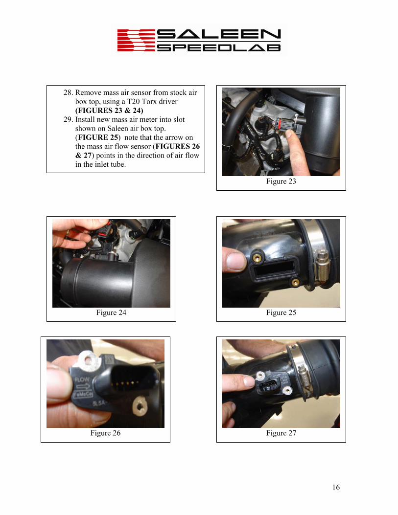
29. Install new mass air meter into slot shown on Saleen air box top. (FIGURE 25) note that the arrow on the mass air flow sensor (FIGURES 26 & 27) points in the direction of air flow in the inlet tube.
Figure 23
Figure 25 Figure 24
Figure 26 Figure 27
17
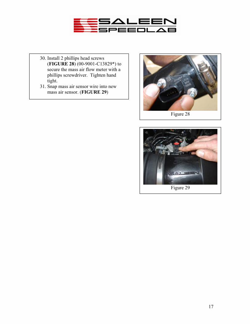
30. Install 2 phillips head screws (FIGURE 28) (00-9001-C13829*) to secure the mass air flow meter with a phillips screwdriver. Tighten hand tight.
31. Snap mass air sensor wire into new mass air sensor. (FIGURE 29)
Figure 28
Figure 29

18
32. Pull off the tamper-proof seal from the front of the supercharger drive pulley.
33. Relieve tension in the belt by using the ½” drive breaker bar to push on the tensioner, and pull the belt off the supercharger drive pulley.
34. Remove the four M6 capscrews from around the center of the pulley, and keep them for the new pulley (FIGURE 30).
35. Put the new pulley (06-1607-C12395A) in place over the drive hub. Put a drop of red Loctite #242 on each M6 capscrew and thread the capscrews in by hand. Torque the 4 capscrews to 90IN-LBS (FIGURE 30).
36. Re-install the belt as shown in the belt routing decal. (FIGURE 31) Use a ½” drive breaker bar to reapply tension after the pulley is installed.
Figure 31
Figure 30


![Sharp 14b Sc,20b Sc,14d Sc [ET]](https://img.pdfslide.us/doc/110x75/545e287eaf795937758b46c4/sharp-14b-sc20b-sc14d-sc-et.jpg)