Embed Size (px)
Citation preview
SERVICE NOTE
SPECIFICATIONS
REPAIR PARTS LIST
DISASSEMBLY ADJUSTMENTS
SERVICE MANUAL
LinkLink
Revision HistoryRevision History
How to useAcrobat Reader
How to useAcrobat Reader
Sony EMCS Co.SAL1870 (3.5-5.6/18-70) (DT 18-70mm F3.5-5.6)
Ver. 1.5 2008.04
LENS FOR DSLR CAMERA
2008D0800-1 © 2008.04
Published by Kohda TEC9-876-947-13
US ModelCanadian Model
AEP ModelChinese Model
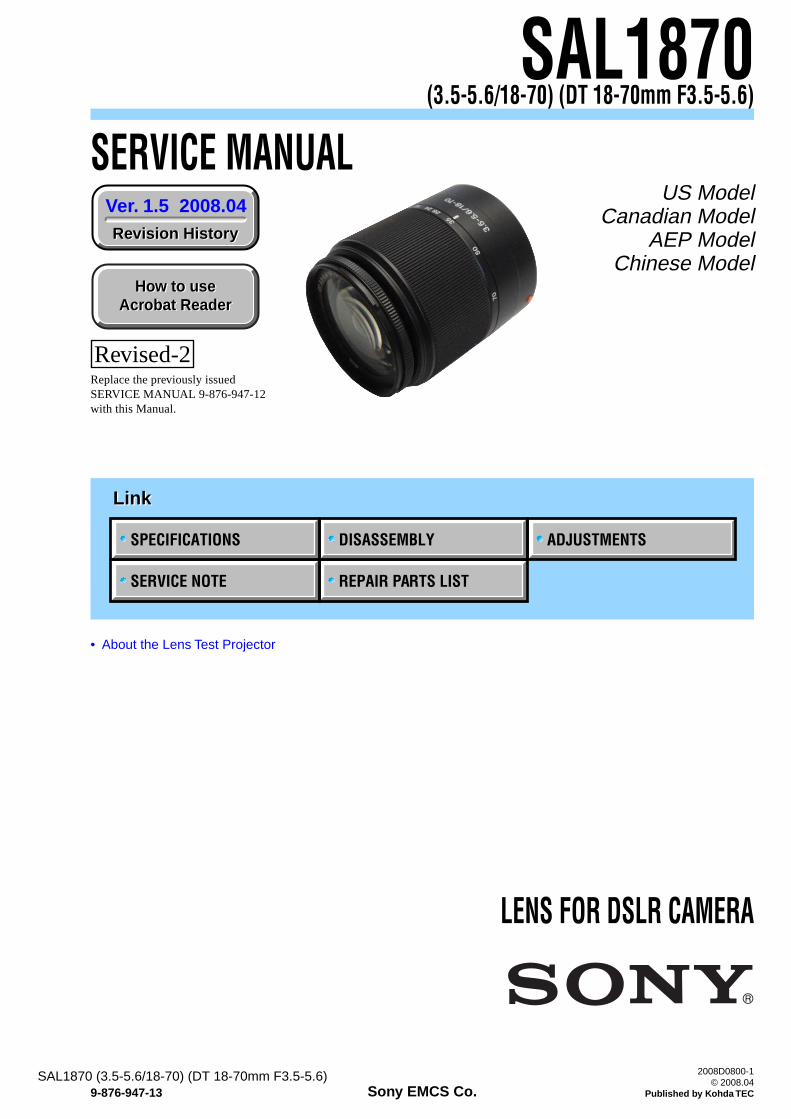
SAL1870(3.5-5.6/18-70) (DT 18-70mm F3.5-5.6)
• About the Lens Test Projector
Revised-2Replace the previously issuedSERVICE MANUAL 9-876-947-12with this Manual.
— 2 —SAL1870 (3.5-5.6/18-70) (DT 18-70mm F3.5-5.6)
SPECIFICATIONS
• This lens is equipped with a distance encoder. The distance encoder allows more accurate measurement (ADI) by using a flash for ADI.• Depending on the lens mechanism, the focal length may change with any change of the shooting distance. The focal length assumes the lens is focused
at infinity.
Equivalent 35mm-format focal length *1 (mm)27-105
Lens groups elements9-11
Angle of view *1
76°-23°*1 The values for equivalent 35mm-format focal length and angle of view are based on Digital Single Lens Reflex Cameras equipped with an APS-
C sized image sensor.Minimum focus *2 (m (feet))
0.38 (1.2)*2 Minimum focus is the shortest distance from the image sensor to the subject.
Maximum magnification (X)0.25
Minimum f-stopf/22-36
Filter diameter (mm)55
Dimensions (maximum diameter ××××× height) (mm (in.))Approx. 66 × 77 (2 5/8 × 3 1/8)
Mass (g (oz.))Approx. 235 (8 5/16)
Included itemsLens (1), Front lens cap (1), Rear lens cap (1), Lens hood (1), Set of printed documentation
Designs and specifications are subject to change without notice.
— 3 —SAL1870 (3.5-5.6/18-70) (DT 18-70mm F3.5-5.6)
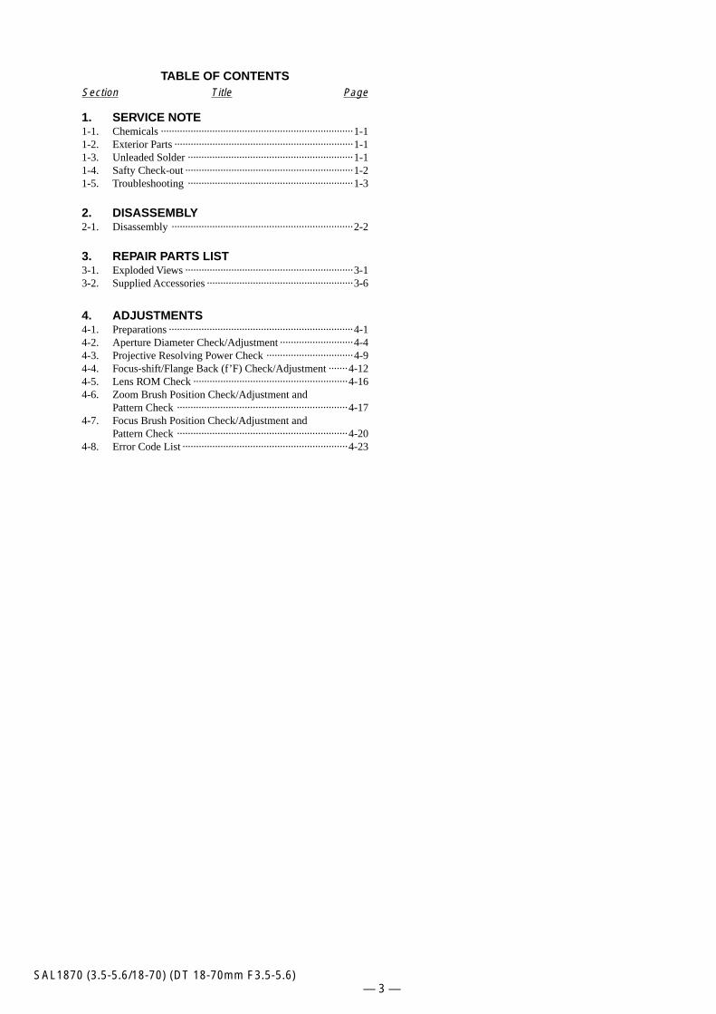
TABLE OF CONTENTSSection Title Page
1. SERVICE NOTE1-1. Chemicals ······································································· 1-11-2. Exterior Parts ·································································· 1-11-3. Unleaded Solder ····························································· 1-11-4. Safty Check-out ······························································ 1-21-5. Troubleshooting ····························································· 1-3
2. DISASSEMBLY2-1. Disassembly ··································································· 2-2
3. REPAIR PARTS LIST3-1. Exploded Views ······························································ 3-13-2. Supplied Accessories ······················································ 3-6
4. ADJUSTMENTS4-1. Preparations ···································································· 4-14-2. Aperture Diameter Check/Adjustment ··························· 4-44-3. Projective Resolving Power Check ································ 4-94-4. Focus-shift/Flange Back (f’F) Check/Adjustment ······· 4-124-5. Lens ROM Check ························································· 4-164-6. Zoom Brush Position Check/Adjustment and
Pattern Check ······························································· 4-174-7. Focus Brush Position Check/Adjustment and
Pattern Check ······························································· 4-204-8. Error Code List ····························································· 4-23
1-1SAL1870 (3.5-5.6/18-70) (DT 18-70mm F3.5-5.6)
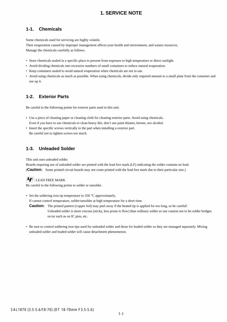
1. SERVICE NOTE
1-1. Chemicals
Some chemicals used for servicing are highly volatile.
Their evaporation caused by improper management affects your health and environment, and wastes resources.
Manage the chemicals carefully as follows.
• Store chemicals sealed in a specific place to prevent from exposure to high temperature or direct sunlight.
• Avoid dividing chemicals into excessive numbers of small containers to reduce natural evaporation.
• Keep containers sealed to avoid natural evaporation when chemicals are not in use.
• Avoid using chemicals as much as possible. When using chemicals, divide only required amount to a small plate from the container and
use up it.
1-2. Exterior Parts
Be careful to the following points for exterior parts used in this unit.
• Use a piece of cleaning paper or cleaning cloth for cleaning exterior parts. Avoid using chemicals.
Even if you have to use chemicals to clean heavy dirt, don’t use paint thinner, ketone, nor alcohol.
• Insert the specific screws vertically to the part when installing a exterior part.
Be careful not to tighten screws too much.
1-3. Unleaded Solder
This unit uses unleaded solder.
Boards requiring use of unleaded solder are printed with the lead free mark (LF) indicating the solder contains no lead.
(Caution: Some printed circuit boards may not come printed with the lead free mark due to their particular size.)
: LEAD FREE MARK
Be careful to the following points to solder or unsolder.
• Set the soldering iron tip temperature to 350 °C approximately.
If cannot control temperature, solder/unsolder at high temperature for a short time.
Caution: The printed pattern (copper foil) may peel away if the heated tip is applied for too long, so be careful!
Unleaded solder is more viscous (sticky, less prone to flow) than ordinary solder so use caution not to let solder bridges
occur such as on IC pins, etc.
• Be sure to control soldering iron tips used for unleaded solder and those for leaded solder so they are managed separately. Mixing
unleaded solder and leaded solder will cause detachment phenomenon.
1-2SAL1870 (3.5-5.6/18-70) (DT 18-70mm F3.5-5.6)
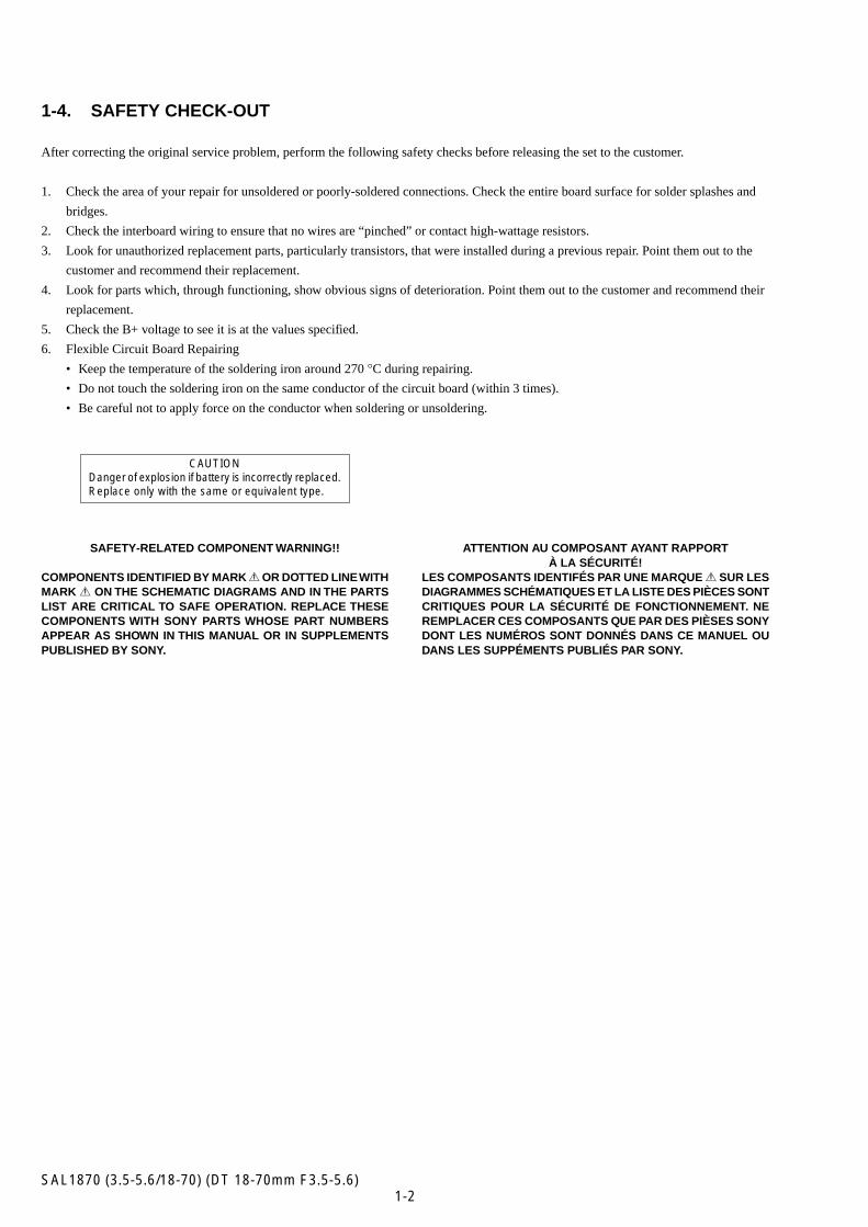
1-4. SAFETY CHECK-OUT
After correcting the original service problem, perform the following safety checks before releasing the set to the customer.
1. Check the area of your repair for unsoldered or poorly-soldered connections. Check the entire board surface for solder splashes and
bridges.
2. Check the interboard wiring to ensure that no wires are “pinched” or contact high-wattage resistors.
3. Look for unauthorized replacement parts, particularly transistors, that were installed during a previous repair. Point them out to the
customer and recommend their replacement.
4. Look for parts which, through functioning, show obvious signs of deterioration. Point them out to the customer and recommend their
replacement.
5. Check the B+ voltage to see it is at the values specified.
6. Flexible Circuit Board Repairing
• Keep the temperature of the soldering iron around 270 °C during repairing.
• Do not touch the soldering iron on the same conductor of the circuit board (within 3 times).
• Be careful not to apply force on the conductor when soldering or unsoldering.
SAFETY-RELATED COMPONENT WARNING!!
COMPONENTS IDENTIFIED BY MARK 0 OR DOTTED LINE WITHMARK 0 ON THE SCHEMATIC DIAGRAMS AND IN THE PARTSLIST ARE CRITICAL TO SAFE OPERATION. REPLACE THESECOMPONENTS WITH SONY PARTS WHOSE PART NUMBERSAPPEAR AS SHOWN IN THIS MANUAL OR IN SUPPLEMENTSPUBLISHED BY SONY.
ATTENTION AU COMPOSANT AYANT RAPPORTÀ LA SÉCURITÉ!
LES COMPOSANTS IDENTIFÉS PAR UNE MARQUE 0 SUR LESDIAGRAMMES SCHÉMATIQUES ET LA LISTE DES PIÈCES SONTCRITIQUES POUR LA SÉCURITÉ DE FONCTIONNEMENT. NEREMPLACER CES COMPOSANTS QUE PAR DES PIÈSES SONYDONT LES NUMÉROS SONT DONNÉS DANS CE MANUEL OUDANS LES SUPPÉMENTS PUBLIÉS PAR SONY.
CAUTIONDanger of explosion if battery is incorrectly replaced.Replace only with the same or equivalent type.
1-3SAL1870 (3.5-5.6/18-70) (DT 18-70mm F3.5-5.6)
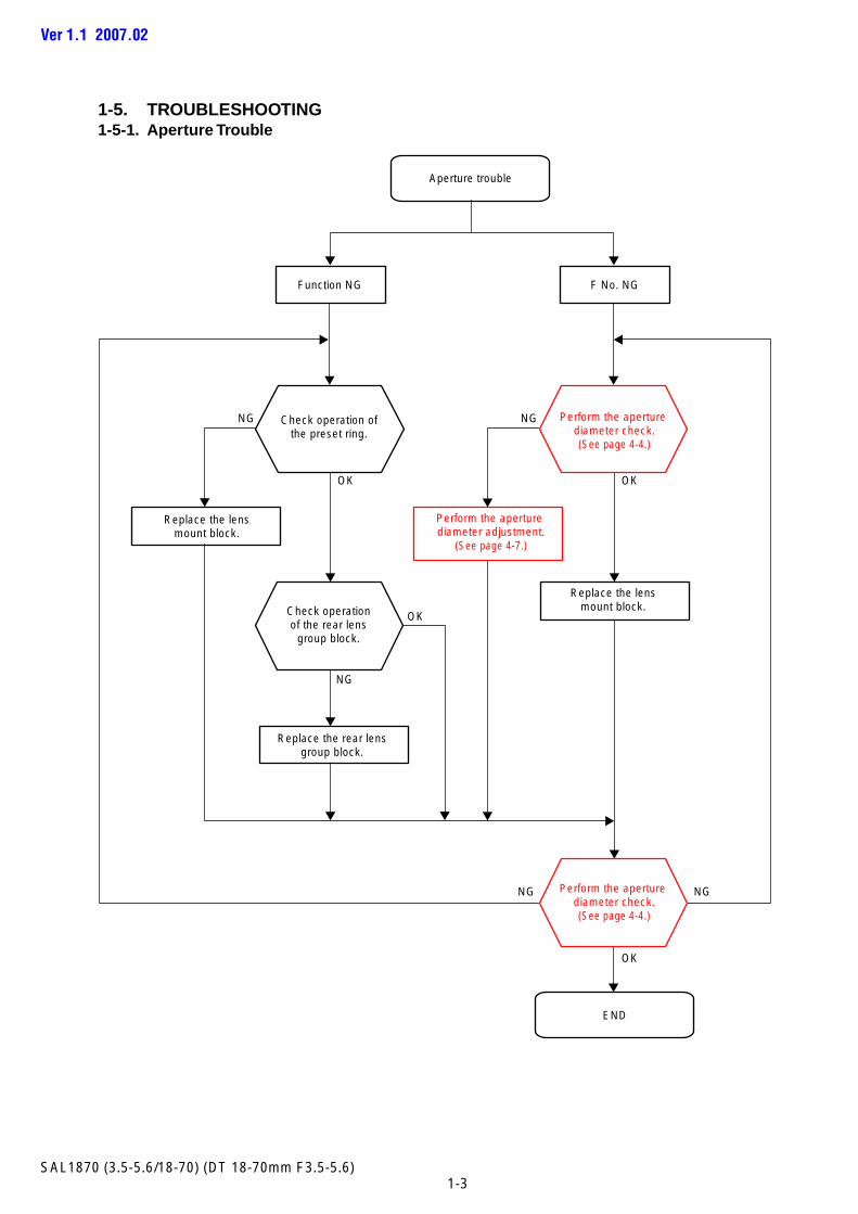
1-5. TROUBLESHOOTING1-5-1. Aperture Trouble
Ver 1.1 2007.02
NG
Check operation ofthe preset ring.
Replace the lensmount block.
Replace the lensmount block.
Perform the aperture diameter adjustment.
(See page 4-7.)
Perform the aperture diameter check.(See page 4-4.)
NG
Check operationof the rear lens
group block.
OK OK
OK
Function NG F No. NG
Aperture trouble
Replace the rear lensgroup block.
NG
NGNG
END
OK
Perform the aperture diameter check.(See page 4-4.)
1-4SAL1870 (3.5-5.6/18-70) (DT 18-70mm F3.5-5.6)
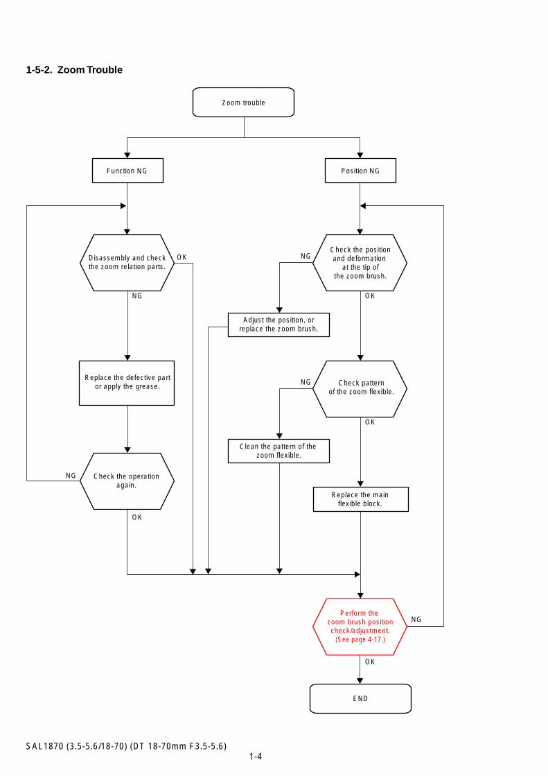
1-5-2. Zoom Trouble
NG
OK
OK
OK
OK
Function NG Position NG
Check the positionand deformation
at the tip ofthe zoom brush.
Adjust the position, orreplace the zoom brush.
Check patternof the zoom flexible.
Clean the pattern of the zoom flexible.
Zoom trouble
Replace the mainflexible block.
Perform the zoom brush positioncheck/adjustment.
(See page 4-17.)
NG
NG
NG
NG
END
OKDisassembly and checkthe zoom relation parts.
Replace the defective partor apply the grease.
Check the operationagain.
1-5SAL1870 (3.5-5.6/18-70) (DT 18-70mm F3.5-5.6)
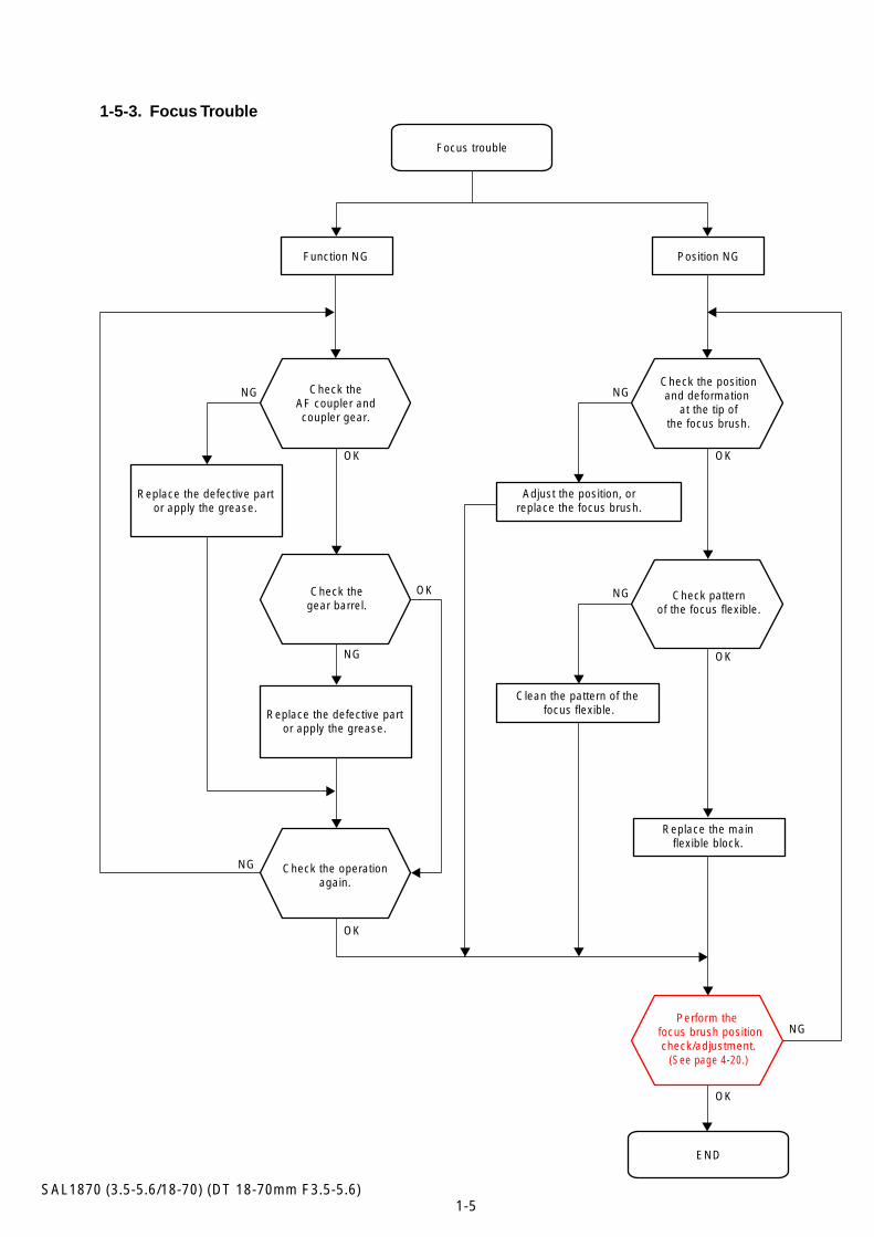
Check the operationagain.
Replace the defective partor apply the grease.
OK
NG
OK
OK
OK
OK
Function NG Position NG
Focus trouble
Replace the defective partor apply the grease.
Check theAF coupler andcoupler gear.
Check thegear barrel.
NGNG
NG
NG
NG
END
OK
Check the positionand deformation
at the tip ofthe focus brush.
Adjust the position, orreplace the focus brush.
Check patternof the focus flexible.
Clean the pattern of the focus flexible.
Replace the mainflexible block.
Perform the focus brush positioncheck/adjustment.
(See page 4-20.)
1-5-3. Focus Trouble
2-1SAL1870 (3.5-5.6/18-70) (DT 18-70mm F3.5-5.6)
Cut and remove the part of gilt which comes off at the point.(Be careful or some pieces of gilt may be left inside)
2. DISASSEMBLY
NOTE FOR REPAIR
• Make sure that the flat cable and flexible board are not cracked of bent at the terminal.Do not insert the cable insufficiently nor crookedly.
• When remove a connector, dont’ pull at wire of connector. It is possible that a wire is snapped.
• When installing a connector, dont’ press down at wire of connector.It is possible that a wire is snapped.
• Do not apply excessive load to the gilded flexible board.
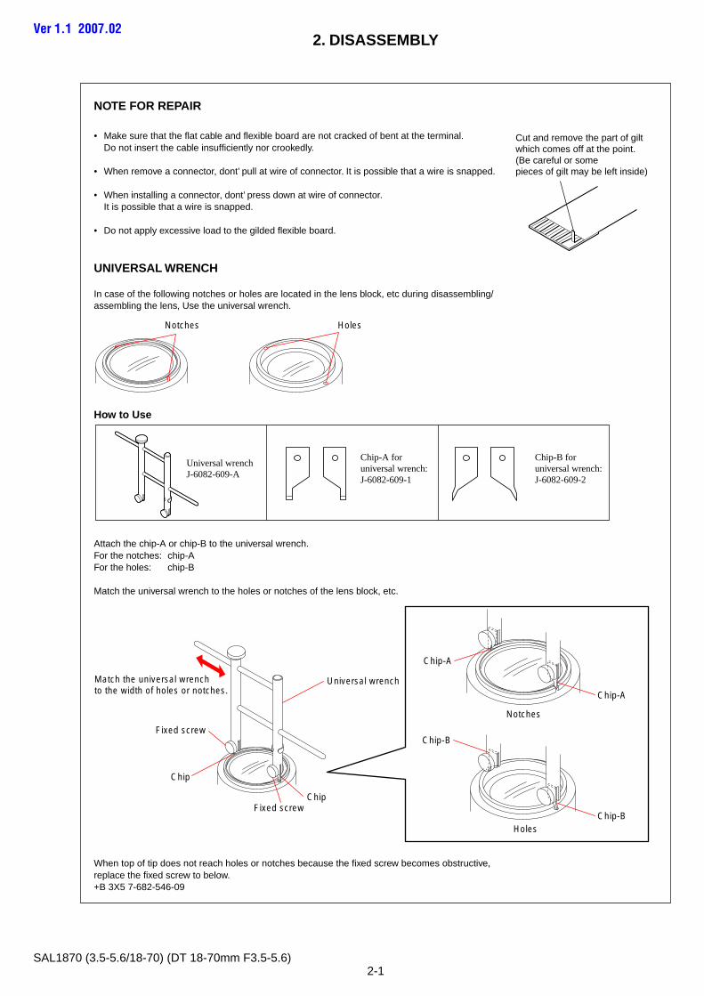
UNIVERSAL WRENCH
In case of the following notches or holes are located in the lens block, etc during disassembling/assembling the lens, Use the universal wrench.
How to Use
Attach the chip-A or chip-B to the universal wrench.For the notches: chip-AFor the holes: chip-B
Match the universal wrench to the holes or notches of the lens block, etc.
When top of tip does not reach holes or notches because the fixed screw becomes obstructive,replace the fixed screw to below.+B 3X5 7-682-546-09
Notches Holes
Universal wrenchJ-6082-609-A
Chip-A for universal wrench:J-6082-609-1
Chip-B for universal wrench:J-6082-609-2
Ver 1.1 2007.02
Notches
Chip-A
Chip-A
Chip-B
Chip-B
ChipFixed screw
Fixed screw
Chip
Match the universal wrench to the width of holes or notches.
Universal wrench
Holes
2-2SAL1870 (3.5-5.6/18-70) (DT 18-70mm F3.5-5.6)
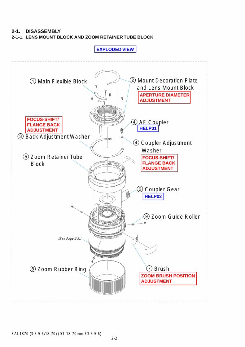
2-1. DISASSEMBLY2-1-1. LENS MOUNT BLOCK AND ZOOM RETAINER TUBE BLOCK
(See Page 2-3.)
2 Mount Decoration Plate1 Main Flexible Block
4 AF Coupler
5 Zoom Retainer Tube Block
6 Coupler Gear
9 Zoom Guide Roller
7 Brush8 Zoom Rubber Ring
3 Back Adjustment Washer 4 Coupler Adjustment
HELP01
HELP02
EXPLODED VIEW
ZOOM BRUSH POSITIONADJUSTMENT
FOCUS-SHIFT/FLANGE BACKADJUSTMENT
FOCUS-SHIFT/FLANGE BACKADJUSTMENT
APERTURE DIAMETERADJUSTMENT
and Lens Mount Block
Washer
2-3SAL1870 (3.5-5.6/18-70) (DT 18-70mm F3.5-5.6)
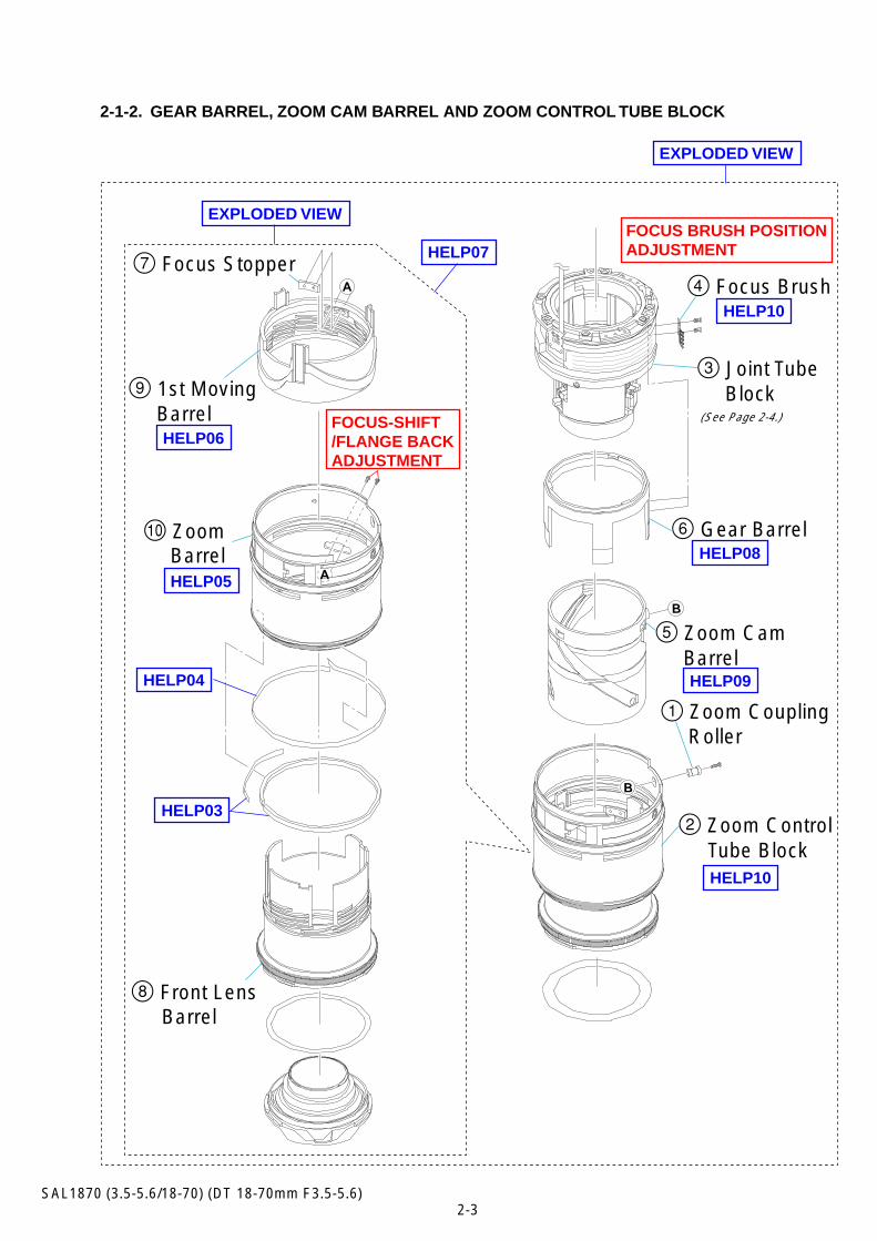
2-1-2. GEAR BARREL, ZOOM CAM BARREL AND ZOOM CONTROL TUBE BLOCK
HELP03
HELP04
HELP05
HELP07
HELP08
HELP09
HELP10
HELP10
HELP06
FOCUS BRUSH POSITIONADJUSTMENT
EXPLODED VIEW
EXPLODED VIEW
(See Page 2-4.)
4 Focus Brush
5 Zoom Cam Barrel
2 Zoom Control
3 Joint Tube Block
1 Zoom Coupling
6 Gear Barrel
7 Focus Stopper
8 Front Lens
9 1st Moving Barrel
0 Zoom
Roller
Tube Block
Barrel
Barrel
FOCUS-SHIFT/FLANGE BACKADJUSTMENT
2-4SAL1870 (3.5-5.6/18-70) (DT 18-70mm F3.5-5.6)
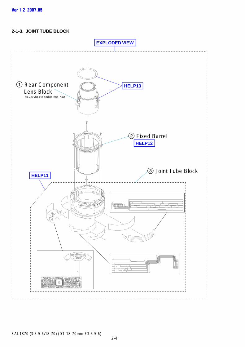
2-1-3. JOINT TUBE BLOCK
2 Fixed Barrel
3 Joint Tube Block
1 Rear Component Lens Block
HELP11
HELP13
HELP12
EXPLODED VIEW
Never disassemble this part.
Ver 1.2 2007.05
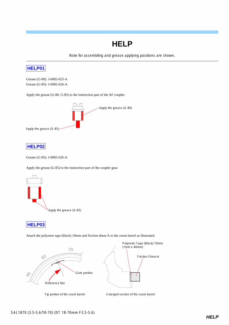
HELPSAL1870 (3.5-5.6/18-70) (DT 18-70mm F3.5-5.6)
Note for assembling and grease applying positions are shown.
HELP01
Grease (G-80): J-6082-625-A
Grease (G-85): J-6082-626-A
Apply the grease (G-80, G-85) to the instruction part of the AF coupler.
HELP02
Grease (G-85): J-6082-626-A
Apply the grease (G-85) to the instruction part of the coupler gear.
HELP03
Attach the polyester tape (black) 10mm and friction sheet-A to the zoom barrel as illustrated.
Apply the grease (G-85)
HELP
Apply the grease (G-85)
Apply the grease (G-80)
Gate portion
Polyester Tape (Black) 10mm(1mm x 40mm)
Friction Sheet-A
Reference line
Tip portion of the zoom barrel Enlarged section of the zoom barrel
HELPSAL1870 (3.5-5.6/18-70) (DT 18-70mm F3.5-5.6)
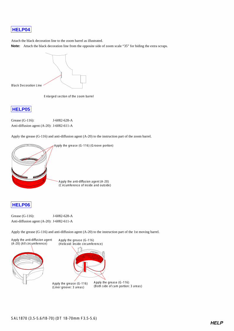
HELP04
Attach the black decoration line to the zoom barrel as illustrated.
Note: Attach the black decoration line from the opposite side of zoom scale “35” for hiding the extra scraps.
HELP05
Grease (G-116): J-6082-628-A
Anti-diffusion agent (A-20): J-6082-611-A
Apply the grease (G-116) and anti-diffusion agent (A-20) to the instruction part of the zoom barrel.
HELP06
Grease (G-116): J-6082-628-A
Anti-diffusion agent (A-20): J-6082-611-A
Apply the grease (G-116) and anti-diffusion agent (A-20) to the instruction part of the 1st moving barrel.
Black Decoration Line
Enlarged section of the zoom barrel
Apply the grease (G-116) (Groove portion)
Apply the anti-diffusion agent (A-20)(Circumference of inside and outside)
Apply the grease (G-116)(Helicoid: Inside circumference)
Apply the anti-diffusion agent(A-20) (All circumference)
Apply the grease (G-116)(Liner groove: 3 areas)
Apply the grease (G-116)(Both side of cam portion: 3 areas)
HELPSAL1870 (3.5-5.6/18-70) (DT 18-70mm F3.5-5.6)
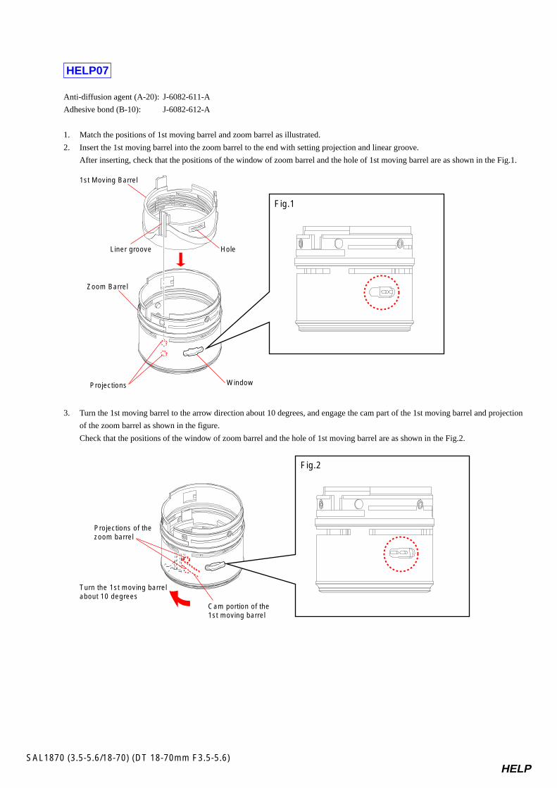
HELP07
Anti-diffusion agent (A-20): J-6082-611-A
Adhesive bond (B-10): J-6082-612-A
1. Match the positions of 1st moving barrel and zoom barrel as illustrated.
2. Insert the 1st moving barrel into the zoom barrel to the end with setting projection and linear groove.
After inserting, check that the positions of the window of zoom barrel and the hole of 1st moving barrel are as shown in the Fig.1.
3. Turn the 1st moving barrel to the arrow direction about 10 degrees, and engage the cam part of the 1st moving barrel and projection
of the zoom barrel as shown in the figure.
Check that the positions of the window of zoom barrel and the hole of 1st moving barrel are as shown in the Fig.2.
1st Moving Barrel
Liner groove
Zoom Barrel
Projections
Hole
Window
Fig.1
Cam portion of the 1st moving barrel
Turn the 1st moving barrelabout 10 degrees
Projections of the zoom barrel
Fig.2
HELPSAL1870 (3.5-5.6/18-70) (DT 18-70mm F3.5-5.6)
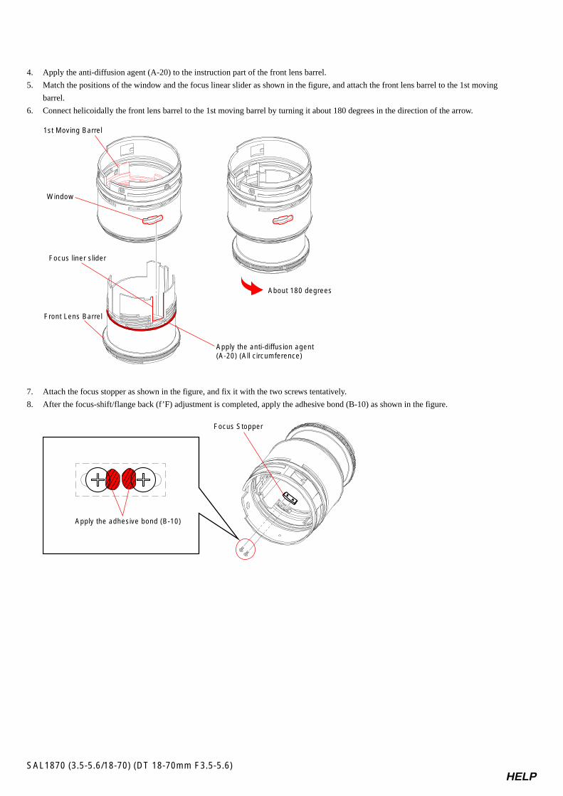
4. Apply the anti-diffusion agent (A-20) to the instruction part of the front lens barrel.
5. Match the positions of the window and the focus linear slider as shown in the figure, and attach the front lens barrel to the 1st moving
barrel.
6. Connect helicoidally the front lens barrel to the 1st moving barrel by turning it about 180 degrees in the direction of the arrow.
7. Attach the focus stopper as shown in the figure, and fix it with the two screws tentatively.
8. After the focus-shift/flange back (f’F) adjustment is completed, apply the adhesive bond (B-10) as shown in the figure.
About 180 degrees
Window
Front Lens Barrel
Focus liner slider
Apply the anti-diffusion agent(A-20) (All circumference)
1st Moving Barrel
Focus Stopper
Apply the adhesive bond (B-10)
HELPSAL1870 (3.5-5.6/18-70) (DT 18-70mm F3.5-5.6)
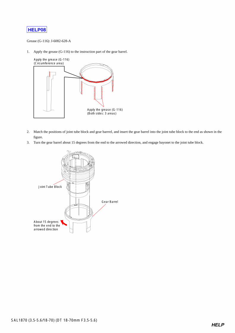
HELP08
Grease (G-116): J-6082-628-A
1. Apply the grease (G-116) to the instruction part of the gear barrel.
2. Match the positions of joint tube block and gear barrrel, and insert the gear barrel into the joint tube block to the end as shown in the
figure.
3. Turn the gear barrel about 15 degrees from the end to the arrowed direction, and engage bayonet to the joint tube block.
Apply the grease (G-116)(Circumference area)
Apply the grease (G-116)(Both sides: 3 areas)
About 15 degrees from the end to the arrowed direction
Gear Barrel
Joint Tube Block
HELPSAL1870 (3.5-5.6/18-70) (DT 18-70mm F3.5-5.6)
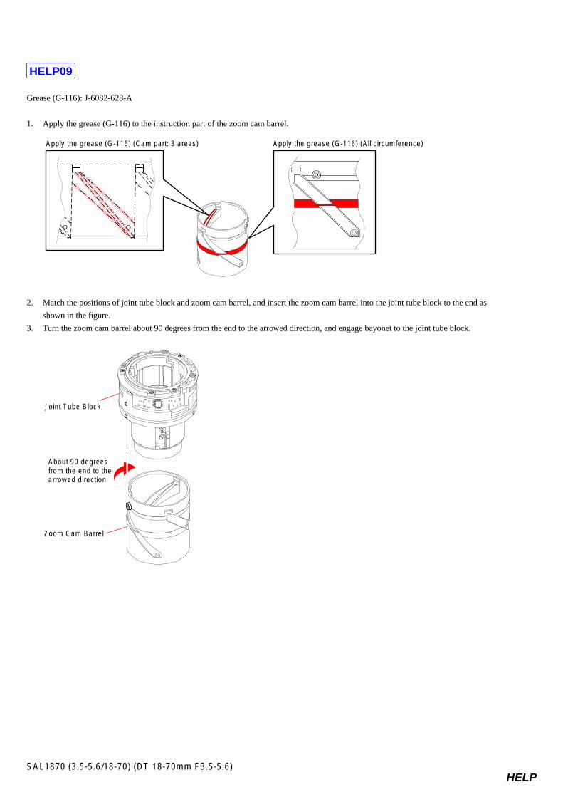
HELP09
Grease (G-116): J-6082-628-A
1. Apply the grease (G-116) to the instruction part of the zoom cam barrel.
2. Match the positions of joint tube block and zoom cam barrel, and insert the zoom cam barrel into the joint tube block to the end as
shown in the figure.
3. Turn the zoom cam barrel about 90 degrees from the end to the arrowed direction, and engage bayonet to the joint tube block.
Apply the grease (G-116) (Cam part: 3 areas) Apply the grease (G-116) (All circumference)
About 90 degrees from the end to the arrowed direction
Joint Tube Block
Zoom Cam Barrel
HELPSAL1870 (3.5-5.6/18-70) (DT 18-70mm F3.5-5.6)
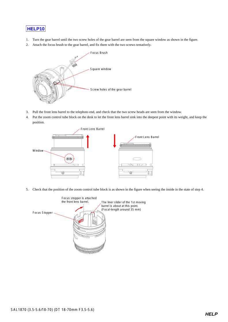
HELP10
1. Turn the gear barrel until the two screw holes of the gear barrel are seen from the square window as shown in the figure.
2. Attach the focus brush to the gear barrel, and fix them with the two screws tentatively.
3. Pull the front lens barrel to the telephoto end, and check that the two screw heads are seen from the window.
4. Put the zoom control tube block on the desk to let the front lens barrel sink into the deepest point with its weight, and keep the
position.
5. Check that the position of the zoom control tube block is as shown in the figure when seeing the inside in the state of step 4.
Square window
Screw holes of the gear barrel
Focus Brush
Window
Front Lens Barrel
Front Lens Barrel
The liner slider of the 1st movingbarrel is about at this point.(Focal-length around 35 mm)
Focus Stopper
Focus stopper is attached the front lens barrel.
HELPSAL1870 (3.5-5.6/18-70) (DT 18-70mm F3.5-5.6)
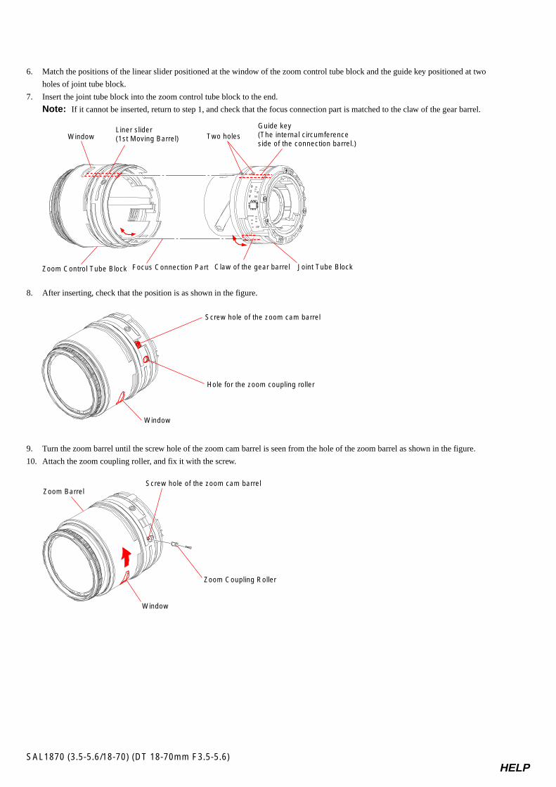
6. Match the positions of the linear slider positioned at the window of the zoom control tube block and the guide key positioned at two
holes of joint tube block.
7. Insert the joint tube block into the zoom control tube block to the end.
Note: If it cannot be inserted, return to step 1, and check that the focus connection part is matched to the claw of the gear barrel.
8. After inserting, check that the position is as shown in the figure.
9. Turn the zoom barrel until the screw hole of the zoom cam barrel is seen from the hole of the zoom barrel as shown in the figure.
10. Attach the zoom coupling roller, and fix it with the screw.
Window
Screw hole of the zoom cam barrel
Hole for the zoom coupling roller
Window
Screw hole of the zoom cam barrel
Zoom Coupling Roller
Zoom Barrel
Window Two holes
Focus Connection Part
Liner slider (1st Moving Barrel)
Guide key(The internal circumference side of the connection barrel.)
Joint Tube BlockZoom Control Tube Block Claw of the gear barrel
HELPSAL1870 (3.5-5.6/18-70) (DT 18-70mm F3.5-5.6)
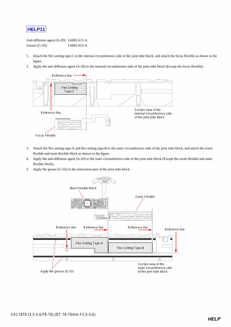
HELP11
Anti-diffusion agent (A-20): J-6082-611-A
Grease (G-55): J-6082-623-A
1. Attach the flex setting tape-C to the internal circumference side of the joint tube block, and attach the focus flexible as shown in the
figure.
2. Apply the anti-diffusion agent (A-20) to the internal circumference side of the joint tube block (Except the focus flexible).
3. Attach the flex setting tape-A and flex setting tape-B to the outer circumference side of the joint tube block, and attach the zoom
flexible and main flexible block as shown in the figure.
4. Apply the anti-diffusion agent (A-20) to the outer circumference side of the joint tube block (Except the zoom flexible and main
flexible block).
5. Apply the grease (G-55) to the instruction part of the joint tube block.
Reference line Reference line Reference lineReference line
Section view of the outer circumference side of the joint tube block
Flex Setting Tape-A
Flex Setting Tape-B
Zoom Flexible
Main Flexible Block
Apply the grease (G-55)
Reference line
Reference lineSection view of the internal circumference side of the joint tube block
Flex SettingTape-C
Focus Flexible
HELPSAL1870 (3.5-5.6/18-70) (DT 18-70mm F3.5-5.6)
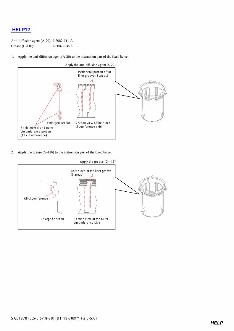
HELP12
Anti-diffusion agent (A-20): J-6082-611-A
Grease (G-116): J-6082-628-A
1. Apply the anti-diffusion agent (A-20) to the instruction part of the fixed barrel.
2. Apply the grease (G-116) to the instruction part of the fixed barrel.
Each internal and outer circumference portion(All circumference)
Peripheral portion of the liner groove (3 areas)
Enlarged section Section view of the outer circumference side
Apply the anti-diffusion agent (A-20)
All circumference
Enlarged section Section view of the outer circumference side
Apply the grease (G-116)
Both sides of the liner groove(3 areas)
HELPSAL1870 (3.5-5.6/18-70) (DT 18-70mm F3.5-5.6)
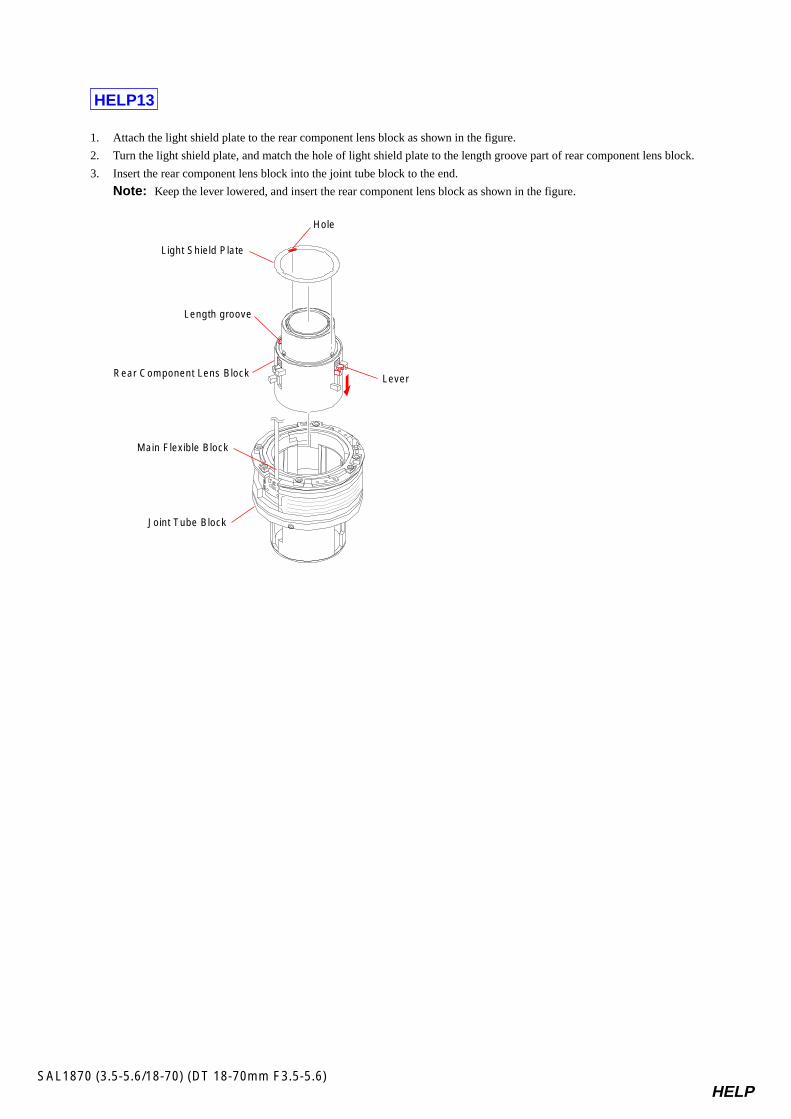
HELP13
1. Attach the light shield plate to the rear component lens block as shown in the figure.
2. Turn the light shield plate, and match the hole of light shield plate to the length groove part of rear component lens block.
3. Insert the rear component lens block into the joint tube block to the end.
Note: Keep the lever lowered, and insert the rear component lens block as shown in the figure.
Hole
Lever
Length groove
Light Shield Plate
Rear Component Lens Block
Main Flexible Block
Joint Tube Block
3-1SAL1870 (3.5-5.6/18-70) (DT 18-70mm F3.5-5.6)
(See Page 3-4.)
(See Page 3-2.)
5(Note 1) 7
(Note 1)
12
1213
11
9
4
3
3
8
10
1516
1312
14(8 x 35 mm)(Note 2)
21
6
13
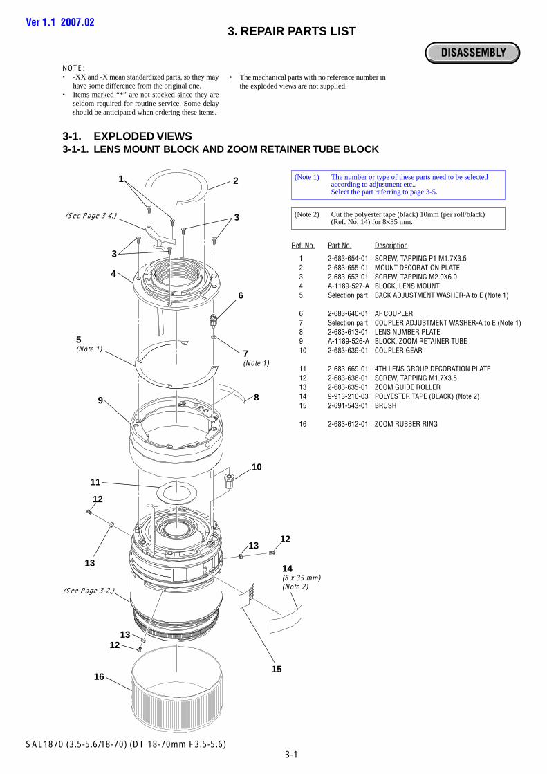
3. REPAIR PARTS LIST
3-1. EXPLODED VIEWS3-1-1. LENS MOUNT BLOCK AND ZOOM RETAINER TUBE BLOCK
DISASSEMBLY
Ref. No. Part No. Description
1 2-683-654-01 SCREW, TAPPING P1 M1.7X3.52 2-683-655-01 MOUNT DECORATION PLATE3 2-683-653-01 SCREW, TAPPING M2.0X6.04 A-1189-527-A BLOCK, LENS MOUNT5 Selection part BACK ADJUSTMENT WASHER-A to E (Note 1)
6 2-683-640-01 AF COUPLER7 Selection part COUPLER ADJUSTMENT WASHER-A to E (Note 1)8 2-683-613-01 LENS NUMBER PLATE9 A-1189-526-A BLOCK, ZOOM RETAINER TUBE10 2-683-639-01 COUPLER GEAR
11 2-683-669-01 4TH LENS GROUP DECORATION PLATE12 2-683-636-01 SCREW, TAPPING M1.7X3.513 2-683-635-01 ZOOM GUIDE ROLLER14 9-913-210-03 POLYESTER TAPE (BLACK) (Note 2)15 2-691-543-01 BRUSH
16 2-683-612-01 ZOOM RUBBER RING
(Note 1) The number or type of these parts need to be selectedaccording to adjustment etc..Select the part referring to page 3-5.
NOTE:• -XX and -X mean standardized parts, so they may
have some difference from the original one.• Items marked “*” are not stocked since they are
seldom required for routine service. Some delayshould be anticipated when ordering these items.
• The mechanical parts with no reference number inthe exploded views are not supplied.
(Note 2) Cut the polyester tape (black) 10mm (per roll/black)(Ref. No. 14) for 8×35 mm.
Ver 1.1 2007.02
3-2SAL1870 (3.5-5.6/18-70) (DT 18-70mm F3.5-5.6)
(See Page 3-4.)
(See Page 3-3.)
52
53
54
55
56
57
51
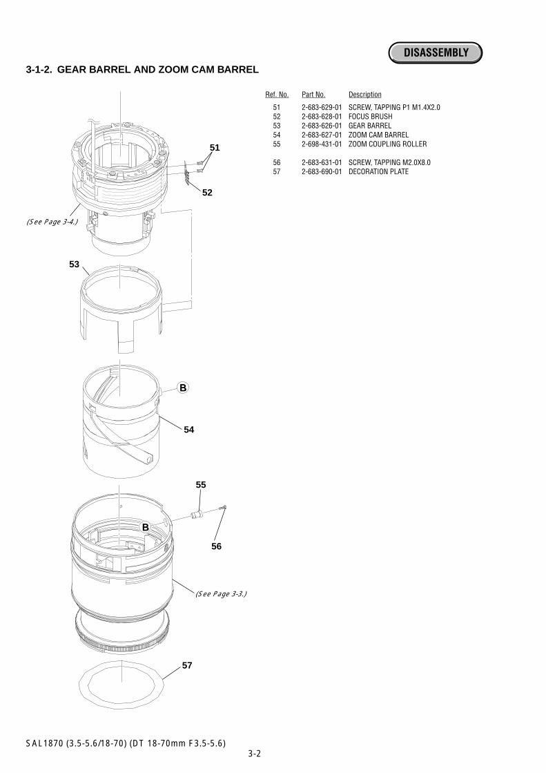
Ref. No. Part No. Description
51 2-683-629-01 SCREW, TAPPING P1 M1.4X2.052 2-683-628-01 FOCUS BRUSH53 2-683-626-01 GEAR BARREL54 2-683-627-01 ZOOM CAM BARREL55 2-698-431-01 ZOOM COUPLING ROLLER
56 2-683-631-01 SCREW, TAPPING M2.0X8.057 2-683-690-01 DECORATION PLATE
3-1-2. GEAR BARREL AND ZOOM CAM BARREL
DISASSEMBLY
3-3SAL1870 (3.5-5.6/18-70) (DT 18-70mm F3.5-5.6)
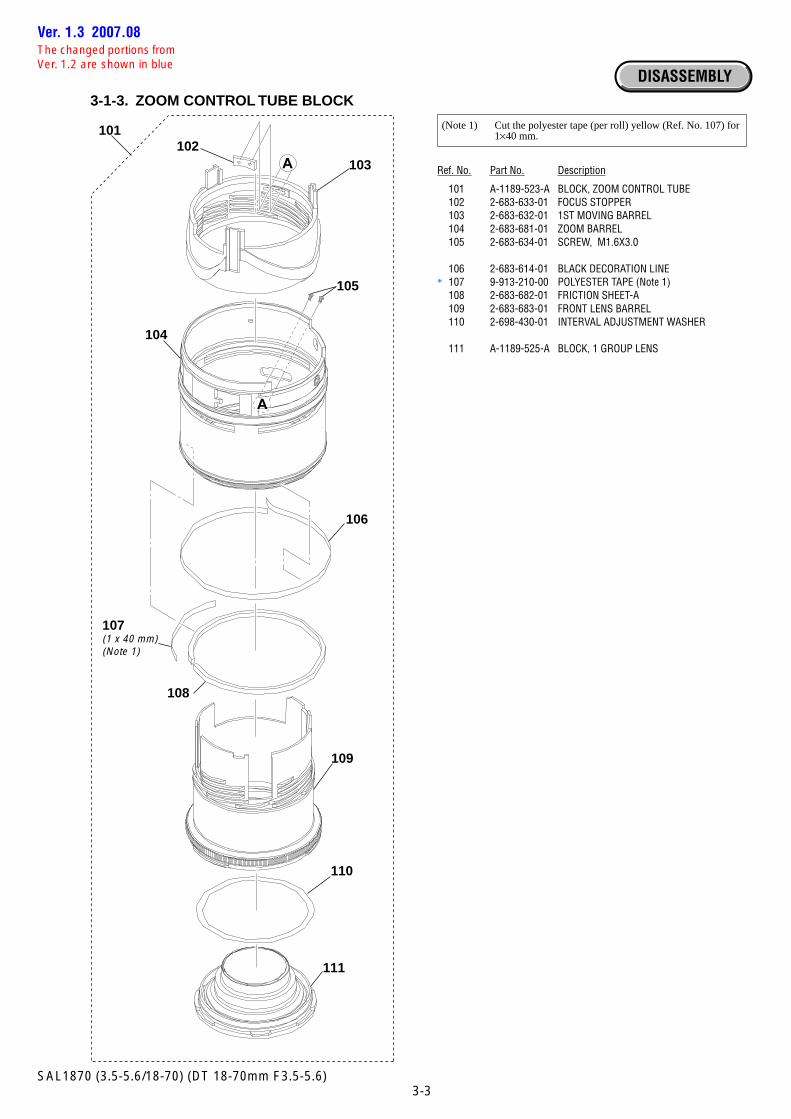
Ref. No. Part No. Description
101 A-1189-523-A BLOCK, ZOOM CONTROL TUBE102 2-683-633-01 FOCUS STOPPER103 2-683-632-01 1ST MOVING BARREL104 2-683-681-01 ZOOM BARREL105 2-683-634-01 SCREW, M1.6X3.0
106 2-683-614-01 BLACK DECORATION LINE* 107 9-913-210-00 POLYESTER TAPE (Note 1)
108 2-683-682-01 FRICTION SHEET-A109 2-683-683-01 FRONT LENS BARREL110 2-698-430-01 INTERVAL ADJUSTMENT WASHER
111 A-1189-525-A BLOCK, 1 GROUP LENS
3-1-3. ZOOM CONTROL TUBE BLOCK
DISASSEMBLY
(Note 1) Cut the polyester tape (per roll) yellow (Ref. No. 107) for1×40 mm.
105
106
101
107(1 x 40 mm)(Note 1)
108
109
110
111
104
103102
Ver. 1.3 2007.08The changed portions fromVer. 1.2 are shown in blue
3-4SAL1870 (3.5-5.6/18-70) (DT 18-70mm F3.5-5.6)
154
160
162
159157
155158
161156
153
151
152(Note 1)
163
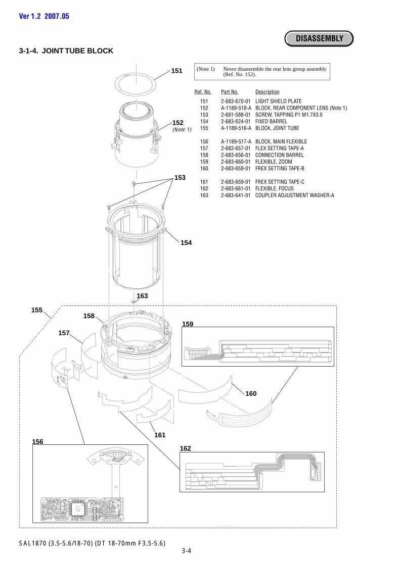
Ref. No. Part No. Description
151 2-683-670-01 LIGHT SHIELD PLATE152 A-1189-518-A BLOCK, REAR COMPONENT LENS (Note 1)153 2-691-588-01 SCREW, TAPPING P1 M1.7X3.5154 2-683-624-01 FIXED BARREL155 A-1189-516-A BLOCK, JOINT TUBE
156 A-1189-517-A BLOCK, MAIN FLEXIBLE157 2-683-657-01 FLEX SETTING TAPE-A158 2-683-656-01 CONNECTION BARREL159 2-683-660-01 FLEXIBLE, ZOOM160 2-683-658-01 FREX SETTING TAPE-B
161 2-683-659-01 FREX SETTING TAPE-C162 2-683-661-01 FLEXIBLE, FOCUS163 2-683-641-01 COUPLER ADJUSTMENT WASHER-A
3-1-4. JOINT TUBE BLOCK
(Note 1) Never disassemble the rear lens group assembly(Ref. No. 152).
DISASSEMBLY
Ver 1.2 2007.05
3-5SAL1870 (3.5-5.6/18-70) (DT 18-70mm F3.5-5.6)
3-1-5. SELECTION PARTS
Ref. No.5These washers are provided for flange back adjustment.Change the thickness (t) according to result of adjustment.
Part No. Description
2-683-648-01 BACK ADJUSTMENT WASHER-A (T=0.05 mm)2-683-649-01 BACK ADJUSTMENT WASHER-B (T=0.07 mm)2-683-650-01 BACK ADJUSTMENT WASHER-C (T=0.1 mm)2-683-651-01 BACK ADJUSTMENT WASHER-D (T=0.2 mm)2-683-652-01 BACK ADJUSTMENT WASHER-E (T=0.5 mm)
Ref. No.7These washers are provided for flange back adjustment.Change the thickness (t) according to result of adjustment.
Part No. Description
2-683-641-01 COUPLER ADJUSTMENT WASHER-A (T=0.05 mm)2-683-642-01 COUPLER ADJUSTMENT WASHER-B (T=0.07 mm)2-683-643-01 COUPLER ADJUSTMENT WASHER-C (T=0.1 mm)2-683-644-01 COUPLER ADJUSTMENT WASHER-D (T=0.2 mm)2-683-645-01 COUPLER ADJUSTMENT WASHER-E (T=0.5 mm)
3-6SAL1870 (3.5-5.6/18-70) (DT 18-70mm F3.5-5.6)
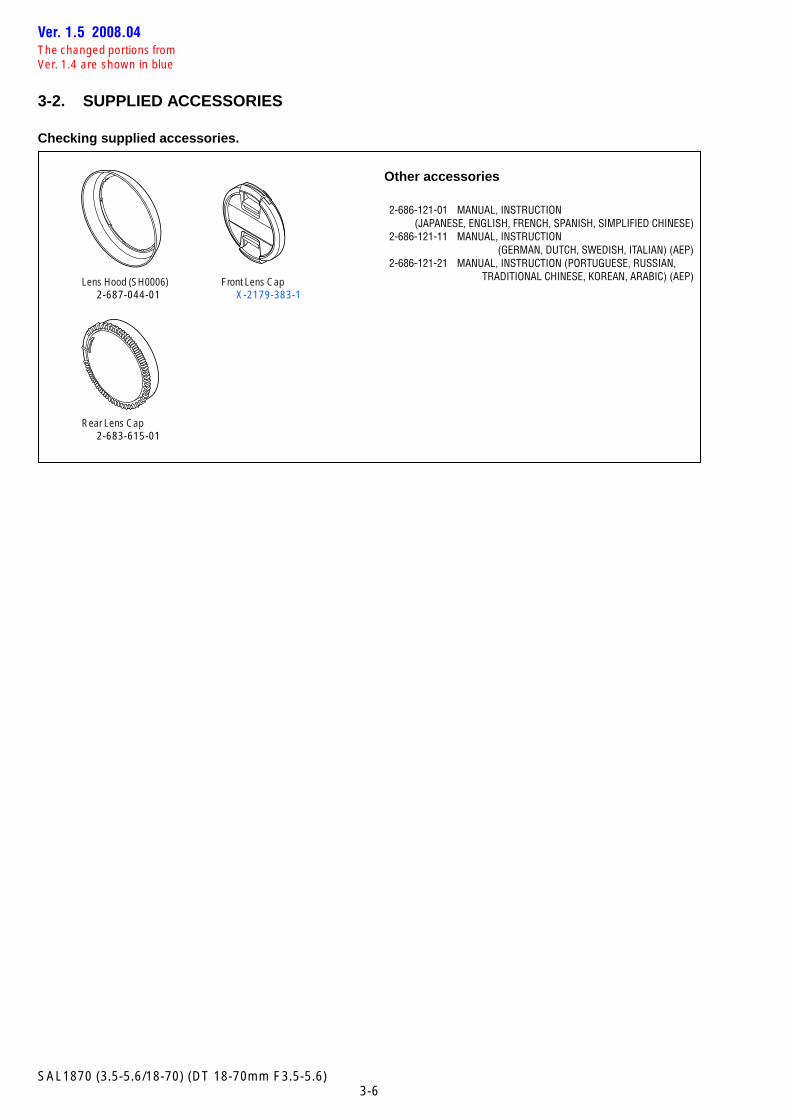
3-2. SUPPLIED ACCESSORIES
Checking supplied accessories.
Other accessories
2-686-121-01 MANUAL, INSTRUCTION(JAPANESE, ENGLISH, FRENCH, SPANISH, SIMPLIFIED CHINESE)
2-686-121-11 MANUAL, INSTRUCTION(GERMAN, DUTCH, SWEDISH, ITALIAN) (AEP)
2-686-121-21 MANUAL, INSTRUCTION (PORTUGUESE, RUSSIAN,TRADITIONAL CHINESE, KOREAN, ARABIC) (AEP)Lens Hood (SH0006)
2-687-044-01Front Lens Cap
X-2179-383-1
Rear Lens Cap2-683-615-01
Ver. 1.5 2008.04The changed portions fromVer. 1.4 are shown in blue
4-1SAL1870 (3.5-5.6/18-70) (DT 18-70mm F3.5-5.6)
4. ADJUSTMENTS
Note: After the service repair, perform the adjustments referring to this section.
4-1. PREPARATIONS
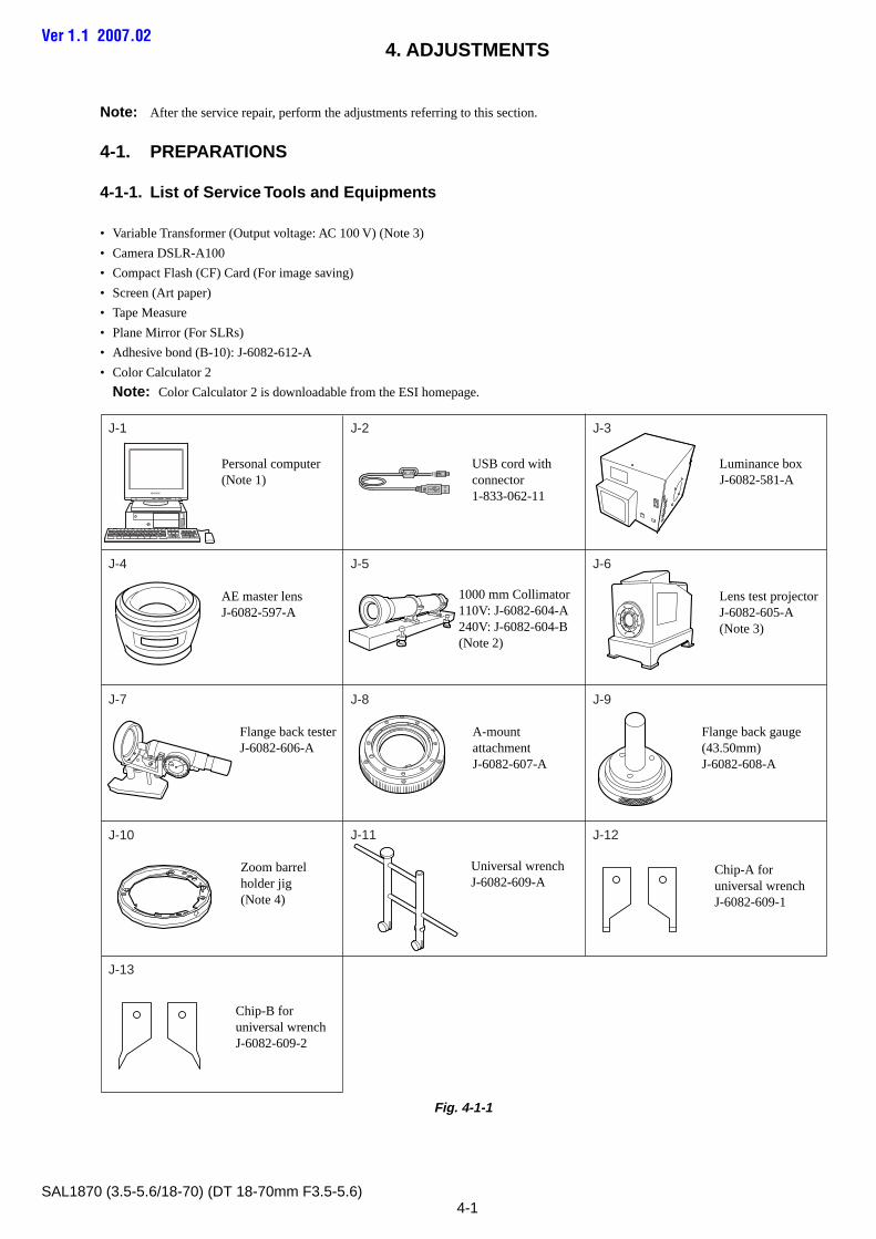
4-1-1. List of Service Tools and Equipments
• Variable Transformer (Output voltage: AC 100 V) (Note 3)
• Camera DSLR-A100
• Compact Flash (CF) Card (For image saving)
• Screen (Art paper)
• Tape Measure
• Plane Mirror (For SLRs)
• Adhesive bond (B-10): J-6082-612-A
• Color Calculator 2
Note: Color Calculator 2 is downloadable from the ESI homepage.
Fig. 4-1-1
Ver 1.1 2007.02
Personal computer(Note 1)
AE master lensJ-6082-597-A
Flange back gauge(43.50mm)J-6082-608-A
Zoom barrelholder jig(Note 4)
Flange back testerJ-6082-606-A
A-mount attachmentJ-6082-607-A
Lens test projectorJ-6082-605-A(Note 3)
1000 mm Collimator110V: J-6082-604-A240V: J-6082-604-B(Note 2)
USB cord withconnector1-833-062-11
Luminance boxJ-6082-581-A
J-1
J-10
J-13
J-9J-7
J-2
J-4 J-6J-5
J-8
J-12J-11
J-3
20
30
4050
60
70 80
900
10
Universal wrenchJ-6082-609-A
Chip-A foruniversal wrenchJ-6082-609-1
Chip-B foruniversal wrenchJ-6082-609-2
4-2SAL1870 (3.5-5.6/18-70) (DT 18-70mm F3.5-5.6)
Note 1: Personal Computer (PC)
(Color Calculator 2 installed)
OS: Windows2000 Professional/XP
MEMORY: 40 M Byte or more recommended
Hard disk free area: 15 M Byte or more recommended
USB terminal: Standard equipment
Graphics: 32,000 colors or more recommended VGA monitor
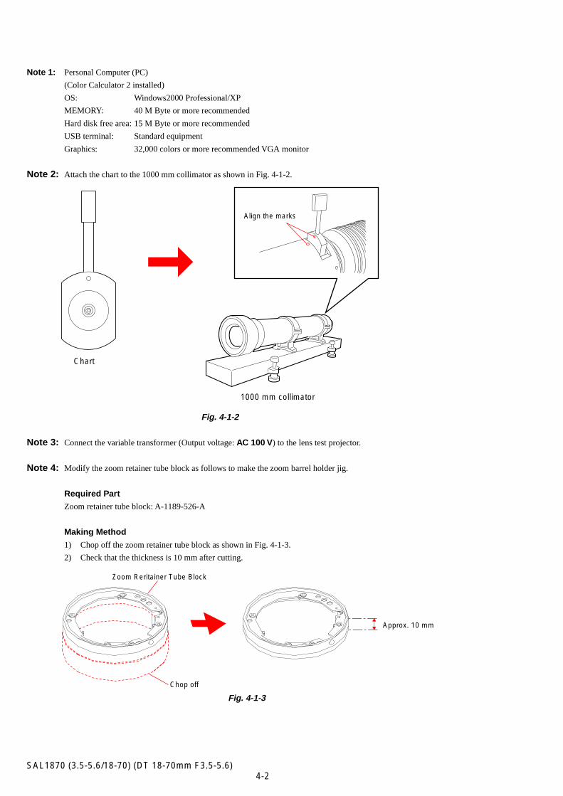
Note 2: Attach the chart to the 1000 mm collimator as shown in Fig. 4-1-2.
Fig. 4-1-2
Note 3: Connect the variable transformer (Output voltage: AC 100 V) to the lens test projector.
Note 4: Modify the zoom retainer tube block as follows to make the zoom barrel holder jig.
Required Part
Zoom retainer tube block: A-1189-526-A
Making Method
1) Chop off the zoom retainer tube block as shown in Fig. 4-1-3.
2) Check that the thickness is 10 mm after cutting.
Fig. 4-1-3
Align the marks
1000 mm collimator
Chart
Approx. 10 mm
Zoom Reritainer Tube Block
Chop off
4-3SAL1870 (3.5-5.6/18-70) (DT 18-70mm F3.5-5.6)
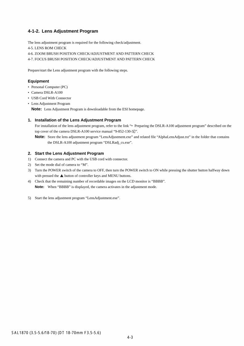
4-1-2. Lens Adjustment Program
The lens adjustment program is required for the following check/adjustment.
4-5. LENS ROM CHECK
4-6. ZOOM BRUSH POSITION CHECK/ADJUSTMENT AND PATTERN CHECK
4-7. FOCUS BRUSH POSITION CHECK/ADJUSTMENT AND PATTERN CHECK
Prepare/start the Lens adjustment program with the following steps.
Equipment• Personal Computer (PC)
• Camera DSLR-A100
• USB Cord With Connector
• Lens Adjustment Program
Note: Lens Adjustment Program is downloadable from the ESI homepage.
1. Installation of the Lens Adjustment ProgramFor installation of the lens adjustment program, refer to the link “• Preparing the DSLR-A100 adjustment program” described on the
top cover of the camera DSLR-A100 service manual “9-852-130-5 ”.
Note: Store the lens adjustment program “LensAdjustment.exe” and related file “AlphaLensAdjust.txt” in the folder that contains
the DSLR-A100 adjustment program “DSLRadj_cs.exe”.
2. Start the Lens Adjustment Program1) Connect the camera and PC with the USB cord with connector.
2) Set the mode dial of camera to “M”.
3) Turn the POWER switch of the camera to OFF, then turn the POWER switch to ON while pressing the shutter button halfway down
with pressed the button of controller keys and MENU buttons.
4) Check that the remaining number of recordable images on the LCD monitor is “BBBB”.
Note: When “BBBB” is displayed, the camera activates in the adjustment mode.
5) Start the lens adjustment program “LensAdjustment.exe”.
4-4SAL1870 (3.5-5.6/18-70) (DT 18-70mm F3.5-5.6)
4-2. APERTURE DIAMETER CHECK/ADJUSTMENT
4-2-1. Aperture Diameter Check
Equipment• Luminance Box
• Camera DSLR-A100
• AE Master Lens
• Compact Flash (CF) Card (For image saving)
• Personal Computer (PC)
(Color Calculator 2 installed)
1. Preparations
Note: Confirm the checking lens by complete. (The adjustment of focus brush and zoom brush is completed.)
1) Install the CF card to the camera.
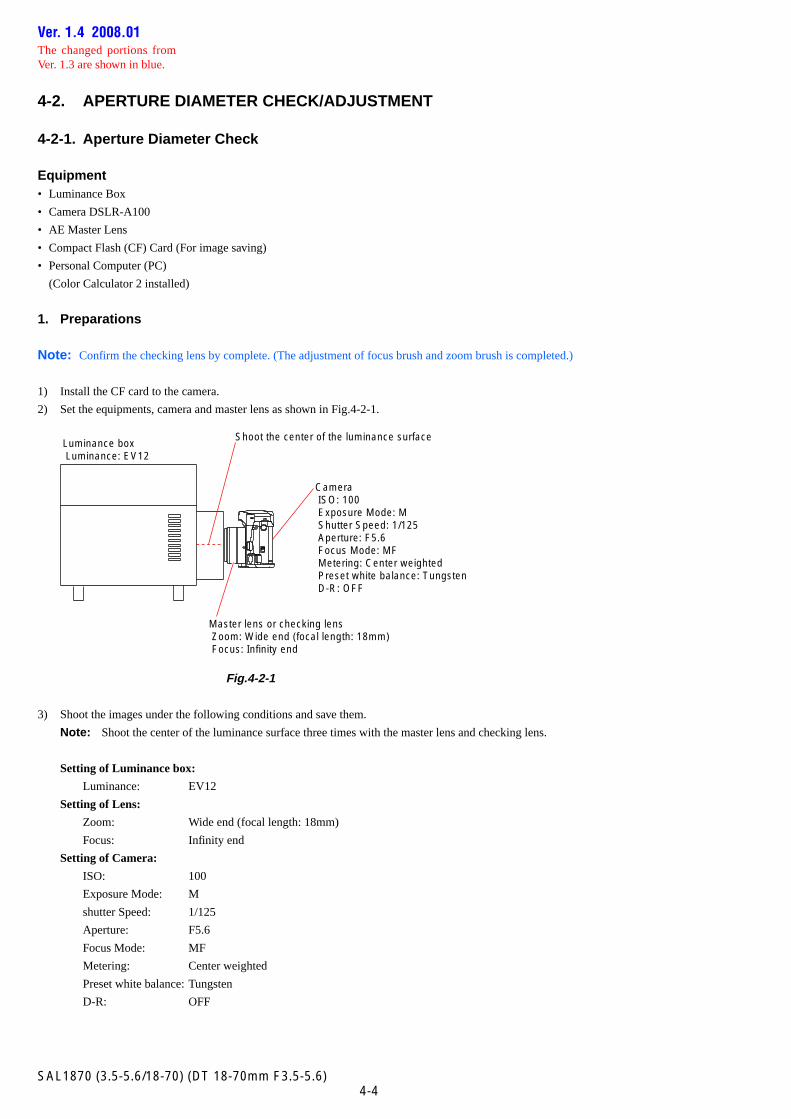
2) Set the equipments, camera and master lens as shown in Fig.4-2-1.
Fig.4-2-1
3) Shoot the images under the following conditions and save them.
Note: Shoot the center of the luminance surface three times with the master lens and checking lens.
Setting of Luminance box:
Luminance: EV12
Setting of Lens:
Zoom: Wide end (focal length: 18mm)
Focus: Infinity end
Setting of Camera:
ISO: 100
Exposure Mode: M
shutter Speed: 1/125
Aperture: F5.6
Focus Mode: MF
Metering: Center weighted
Preset white balance: Tungsten
D-R: OFF
Luminance box Luminance: EV12
Camera ISO: 100 Exposure Mode: M Shutter Speed: 1/125 Aperture: F5.6 Focus Mode: MF Metering: Center weighted Preset white balance: Tungsten D-R: OFF
Master lens or checking lens Zoom: Wide end (focal length: 18mm) Focus: Infinity end
Shoot the center of the luminance surface
Ver. 1.4 2008.01The changed portions fromVer. 1.3 are shown in blue.
4-5SAL1870 (3.5-5.6/18-70) (DT 18-70mm F3.5-5.6)
kkkkk
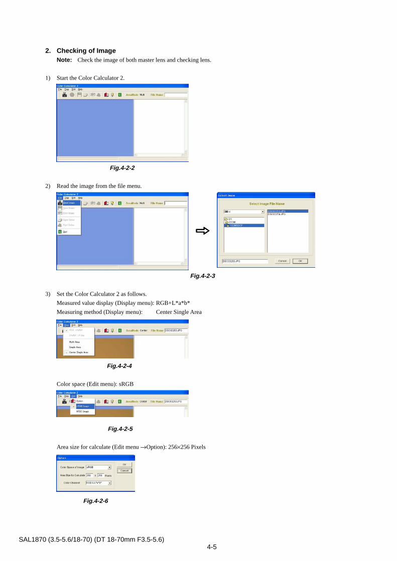
2. Checking of ImageNote: Check the image of both master lens and checking lens.
1) Start the Color Calculator 2.
Fig.4-2-2
2) Read the image from the file menu.
Fig.4-2-3
3) Set the Color Calculator 2 as follows.
Measured value display (Display menu): RGB+L*a*b*
Measuring method (Display menu): Center Single Area
Fig.4-2-4
Color space (Edit menu): sRGB
Fig.4-2-5
Area size for calculate (Edit menu →Option): 256×256 Pixels
Fig.4-2-6
4-6SAL1870 (3.5-5.6/18-70) (DT 18-70mm F3.5-5.6)
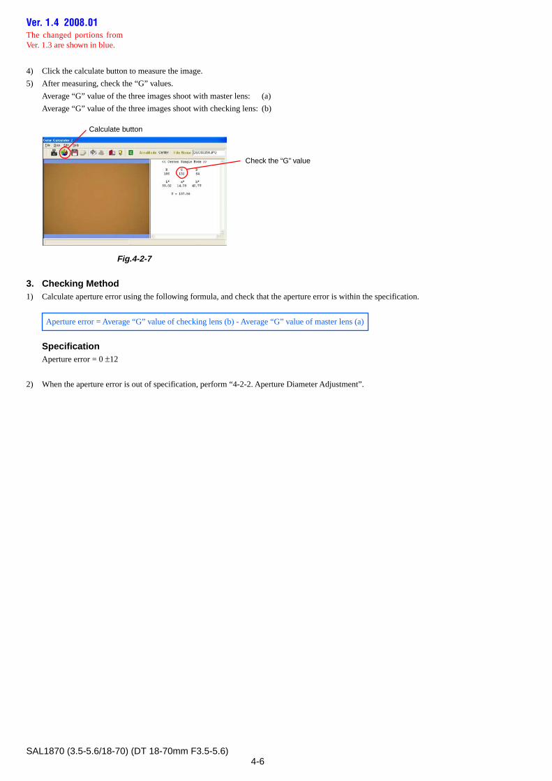
4) Click the calculate button to measure the image.
5) After measuring, check the “G” values.
Average “G” value of the three images shoot with master lens: (a)
Average “G” value of the three images shoot with checking lens: (b)
Fig.4-2-7
3. Checking Method1) Calculate aperture error using the following formula, and check that the aperture error is within the specification.
Aperture error = Average “G” value of checking lens (b) - Average “G” value of master lens (a)
SpecificationAperture error = 0 ±12
2) When the aperture error is out of specification, perform “4-2-2. Aperture Diameter Adjustment”.
Calculate button
Check the “G” value
Ver. 1.4 2008.01The changed portions fromVer. 1.3 are shown in blue.
4-7SAL1870 (3.5-5.6/18-70) (DT 18-70mm F3.5-5.6)
4-2-2. Aperture Diameter Adjustment
Equipment
Equipment• Luminance Box
• Camera DSLR-A100
• AE Master Lens
• Compact Flash (CF) Card (For image saving)
• Personal Computer (PC)
(Color Calculator 2 installed)
• Adhesive bond (B-10)
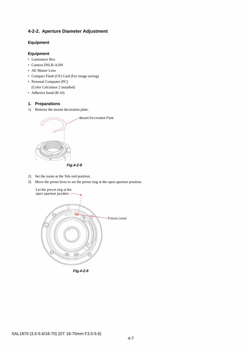
1. Preparations1) Remove the mount decoration plate.
Fig.4-2-8
2) Set the zoom at the Tele end position.
3) Move the preset lever to set the preset ring at the open aperture position.
Fig.4-2-9
Mount Decoration Plate
Set the preset ring at theopen aperture position.
Preset Lever
4-8SAL1870 (3.5-5.6/18-70) (DT 18-70mm F3.5-5.6)
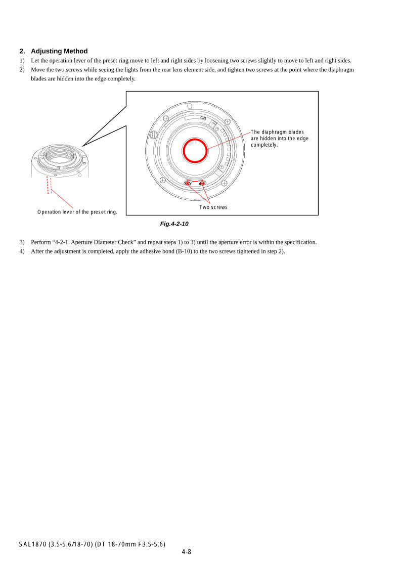
2. Adjusting Method1) Let the operation lever of the preset ring move to left and right sides by loosening two screws slightly to move to left and right sides.
2) Move the two screws while seeing the lights from the rear lens element side, and tighten two screws at the point where the diaphragm
blades are hidden into the edge completely.
Fig.4-2-10
3) Perform “4-2-1. Aperture Diameter Check” and repeat steps 1) to 3) until the aperture error is within the specification.
4) After the adjustment is completed, apply the adhesive bond (B-10) to the two screws tightened in step 2).
Operation lever of the preset ring.
The diaphragm bladesare hidden into the edgecompletely.
Two screws
4-9SAL1870 (3.5-5.6/18-70) (DT 18-70mm F3.5-5.6)
4-3. PROJECTIVE RESOLVING POWER CHECK
Equipment• Lens Test Projector and Variable Transformer (Output voltage: AC 100 V)
Note: Connect the variable transformer (Output voltage: AC 100 V) to the lens test projector.
• A-mount Attachment
• Screen (Art paper)
• Tape Measure
• Plane Mirror (For SLRs)
1. PreparationsNote: Check the projective resolving power of the checking lens at the following focal-length and distance.
Focal-length f (mm) distance (m)
18 0.84
35 1.49
70 2.82
Table 4-3-1
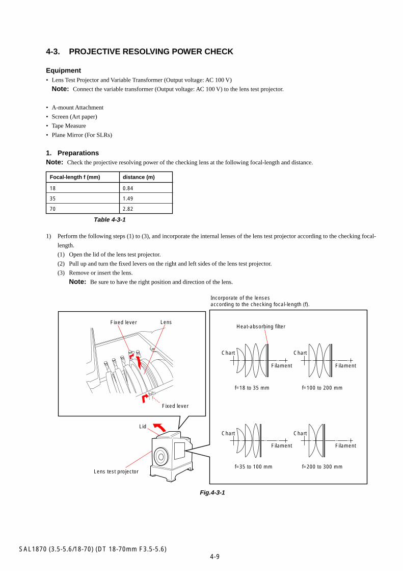
1) Perform the following steps (1) to (3), and incorporate the internal lenses of the lens test projector according to the checking focal-
length.
(1) Open the lid of the lens test projector.
(2) Pull up and turn the fixed levers on the right and left sides of the lens test projector.
(3) Remove or insert the lens.
Note: Be sure to have the right position and direction of the lens.
Fig.4-3-1
Lens test projector
Incorporate of the lensesaccording to the checking focal-length (f).
Lens
Fixed lever
Fixed lever
Lid
f=18 to 35 mm
f=35 to 100 mm
f=100 to 200 mm
f=200 to 300 mm
Heat-absorbing filter
ChartChart
ChartChart
Filament Filament
Filament Filament
4-10SAL1870 (3.5-5.6/18-70) (DT 18-70mm F3.5-5.6)
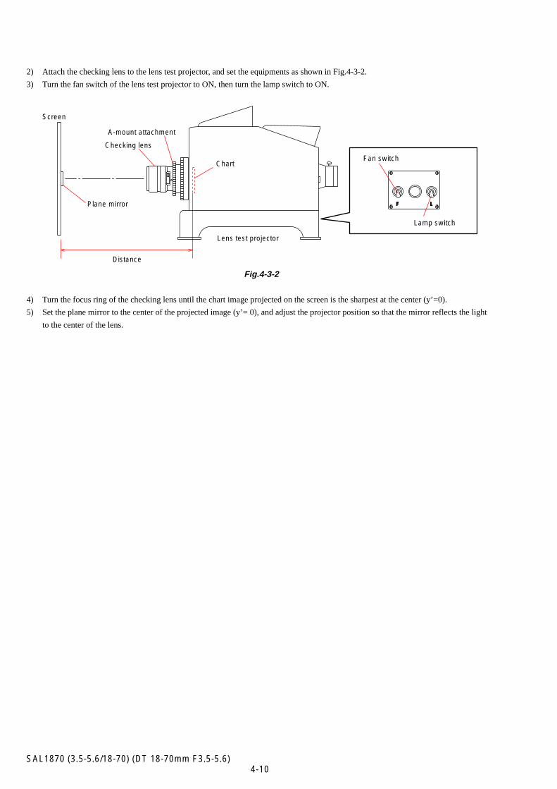
2) Attach the checking lens to the lens test projector, and set the equipments as shown in Fig.4-3-2.
3) Turn the fan switch of the lens test projector to ON, then turn the lamp switch to ON.
Fig.4-3-2
4) Turn the focus ring of the checking lens until the chart image projected on the screen is the sharpest at the center (y’=0).
5) Set the plane mirror to the center of the projected image (y’= 0), and adjust the projector position so that the mirror reflects the light
to the center of the lens.
Distance
Lens test projector
ChartFan switch
Lamp switch
Plane mirror
Screen
A-mount attachment
Checking lens
F L
4-11SAL1870 (3.5-5.6/18-70) (DT 18-70mm F3.5-5.6)
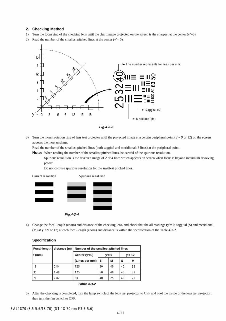
2. Checking Method1) Turn the focus ring of the checking lens until the chart image projected on the screen is the sharpest at the center (y’=0).
2) Read the number of the smallest pitched lines at the center (y’= 0).
Fig.4-3-3
3) Turn the mount rotation ring of lens test projector until the projected image at a certain peripheral point (y’= 9 or 12) on the screen
appears the most unsharp.
Read the number of the smallest pitched lines (both saggital and meridional: 3 lines) at the peripheral point.
Note: When reading the number of the smallest pitched lines, be careful of the spurious resolution.
Spurious resolution is the reversed image of 2 or 4 lines which appears on screen when focus is beyond maximum revolving
power.
Do not confuse spurious resolution for the smallest pitched lines.
Fig.4-3-4
4) Change the focal-length (zoom) and distance of the checking lens, and check that the all readings (y’= 0, saggital (S) and meridional
(M) at y’= 9 or 12) at each focal-length (zoom) and distance is within the specification of the Table 4-3-2.
Specification
Focal-length distance (m) Number of the smallest pitched lines
f (mm) Center (y’=0) y’= 9 y’= 12
(Lines per mm) S M S M
18 0.84 125 50 40 40 32
35 1.49 125 50 40 40 32
70 2.82 80 40 25 40 20
Table 4-3-2
5) After the checking is completed, turn the lamp switch of the lens test projector to OFF and cool the inside of the lens test projector,
then turn the fan switch to OFF.
The number represents for lines per mm.
Saggital (S)
Meridional (M)
Correct resolution Spurious resolution
4-12SAL1870 (3.5-5.6/18-70) (DT 18-70mm F3.5-5.6)
4-4. FOCUS-SHIFT/FLANGE BACK (f’F) CHECK/ADJUSTMENT
4-4-1. Focus-shift/Flange Back (f’F) Check
Equipment• 1000 mm Collimator
• Flange Back Tester
• A-mount Attachment
• Flange Back Gauge (43.50mm)
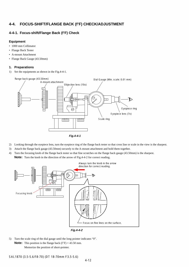
1. Preparations1) Set the equipments as shown in the Fig.4-4-1.
Fig.4-4-1
2) Looking through the eyepiece lens, turn the eyepiece ring of the flange back tester so that cross line or scale in the view is the sharpest.
3) Attach the flange back gauge (43.50mm) securely to the A-mount attachment and hold them together.
4) Turn the focusing knob of the flange back tester so that fine scratches on the flange back gauge (43.50mm) is the sharpest.
Note: Turn the knob in the direction of the arrow of Fig.4-4-2 for correct reading.
Fig.4-4-2
5) Turn the scale ring of the dial gauge until the long pointer indicates “0”.
Note: This position is the flange back (f’F) = 43.50 mm.
Memorize the position of short-pointer.
flange back gauge (43.50mm)A-mount attachment
Objective lens (10x)
Dial Gauge (Min. scale: 0.01 mm)
Scale ring
Eyepiece lens (7x)
Eyepiece ring
Focusing knob
Focus on fine lines on the surface.
Always turn the knob in the arrowdirection for correct reading.
4-13SAL1870 (3.5-5.6/18-70) (DT 18-70mm F3.5-5.6)
Optical AlignmentBest alignment
Incorrect alignede.g. As the focusing knob is turned, the chart may appear blurry as illustrated.The cause depends on individual lens.
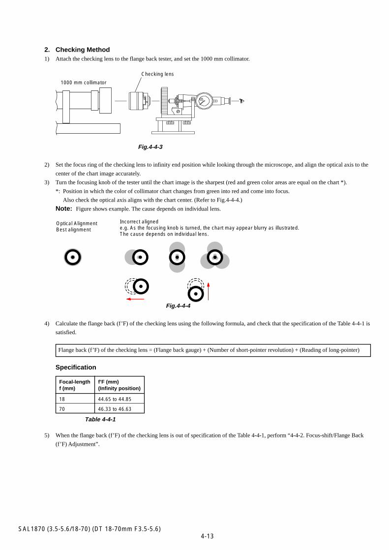
2. Checking Method1) Attach the checking lens to the flange back tester, and set the 1000 mm collimator.
Fig.4-4-3
2) Set the focus ring of the checking lens to infinity end position while looking through the microscope, and align the optical axis to the
center of the chart image accurately.
3) Turn the focusing knob of the tester until the chart image is the sharpest (red and green color areas are equal on the chart *).
*: Position in which the color of collimator chart changes from green into red and come into focus.
Also check the optical axis aligns with the chart center. (Refer to Fig.4-4-4.)
Note: Figure shows example. The cause depends on individual lens.
Fig.4-4-4
4) Calculate the flange back (f’F) of the checking lens using the following formula, and check that the specification of the Table 4-4-1 is
satisfied.
Flange back (f’F) of the checking lens = (Flange back gauge) + (Number of short-pointer revolution) + (Reading of long-pointer)
Specification
Focal-length f’F (mm)f (mm) (Infinity position)
18 44.65 to 44.85
70 46.33 to 46.63
Table 4-4-1
5) When the flange back (f’F) of the checking lens is out of specification of the Table 4-4-1, perform “4-4-2. Focus-shift/Flange Back
(f’F) Adjustment”.
1000 mm collimator
Checking lens
4-14SAL1870 (3.5-5.6/18-70) (DT 18-70mm F3.5-5.6)
4-4-2. Focus-shift/Flange Back (f’F) Adjustment
Equipment• 1000 mm Collimator
• Flange Back Tester
• A-mount Attachment
• Flange Back Gauge (43.50mm)
• Adhesive bond (B-10)
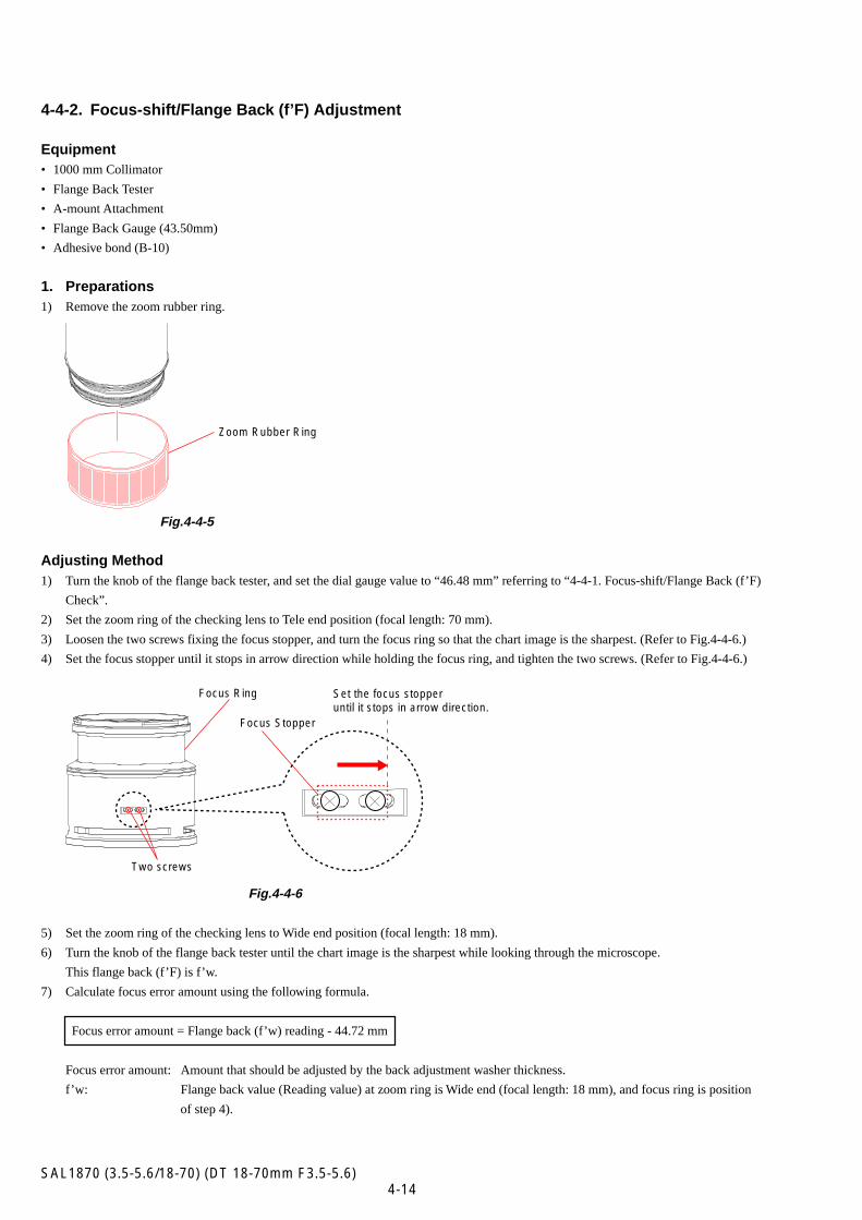
1. Preparations1) Remove the zoom rubber ring.
Fig.4-4-5
Adjusting Method1) Turn the knob of the flange back tester, and set the dial gauge value to “46.48 mm” referring to “4-4-1. Focus-shift/Flange Back (f’F)
Check”.
2) Set the zoom ring of the checking lens to Tele end position (focal length: 70 mm).
3) Loosen the two screws fixing the focus stopper, and turn the focus ring so that the chart image is the sharpest. (Refer to Fig.4-4-6.)
4) Set the focus stopper until it stops in arrow direction while holding the focus ring, and tighten the two screws. (Refer to Fig.4-4-6.)
Fig.4-4-6
5) Set the zoom ring of the checking lens to Wide end position (focal length: 18 mm).
6) Turn the knob of the flange back tester until the chart image is the sharpest while looking through the microscope.
This flange back (f’F) is f’w.
7) Calculate focus error amount using the following formula.
Focus error amount = Flange back (f’w) reading - 44.72 mm
Focus error amount: Amount that should be adjusted by the back adjustment washer thickness.
f’w: Flange back value (Reading value) at zoom ring is Wide end (focal length: 18 mm), and focus ring is position
of step 4).
Two screws
Focus Ring
Focus Stopper
Set the focus stopper until it stops in arrow direction.
Zoom Rubber Ring
4-15SAL1870 (3.5-5.6/18-70) (DT 18-70mm F3.5-5.6)
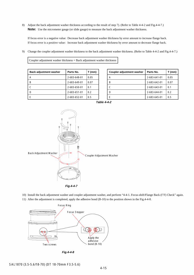
Table 4-4-2
Fig.4-4-7
10) Install the back adjustment washer and coupler adjustment washer, and perform “4-4-1. Focus-shift/Flange Back (f’F) Check” again.
11) After the adjustment is completed, apply the adhesive bond (B-10) to the position shown in the Fig.4-4-8.
Fig.4-4-8
Back adjustment washer Parts No. T (mm)
A 2-683-648-01 0.05
B 2-683-649-01 0.07
C 2-683-650-01 0.1
D 2-683-651-01 0.2
E 2-683-652-01 0.5
8) Adjust the back adjustment washer thickness according to the result of step 7). (Refer to Table 4-4-2 and Fig.4-4-7.)
Note: Use the micrometer gauge (or slide gauge) to measure the back adjustment washer thickness.
If focus error is a negative value: Decrease back adjustment washer thickness by error amount to increase flange back.
If focus error is a positive value: Increase back adjustment washer thickness by error amount to decrease flange back.
9) Change the coupler adjustment washer thickness to the back adjustment washer thickness. (Refer to Table 4-4-2 and Fig.4-4-7.)
Coupler adjustment washer thickness = Back adjustment washer thickness
Coupler adjustment washer Parts No. T (mm)
A 2-683-641-01 0.05
B 2-683-642-01 0.07
C 2-683-643-01 0.1
D 2-683-644-01 0.2
E 2-683-645-01 0.5
Back Adjustment WasherCoupler Adjustment Washer
Apply the adhesive bond (B-10)Two screws
Focus Ring
Focus Stopper
4-16SAL1870 (3.5-5.6/18-70) (DT 18-70mm F3.5-5.6)
4-5. LENS ROM CHECK
Note: If dialog box of error code appears during the checking, check the reason of error referring to page 4-23.
Equipment• Personal Computer (PC)
• Camera DSLR-A100
• USB Cord With Connector
• Lens Adjustment Program
Note: Lens Adjustment Program is downloadable from the ESI homepage.
1. Preparations1) Connect the checking lens to the camera.
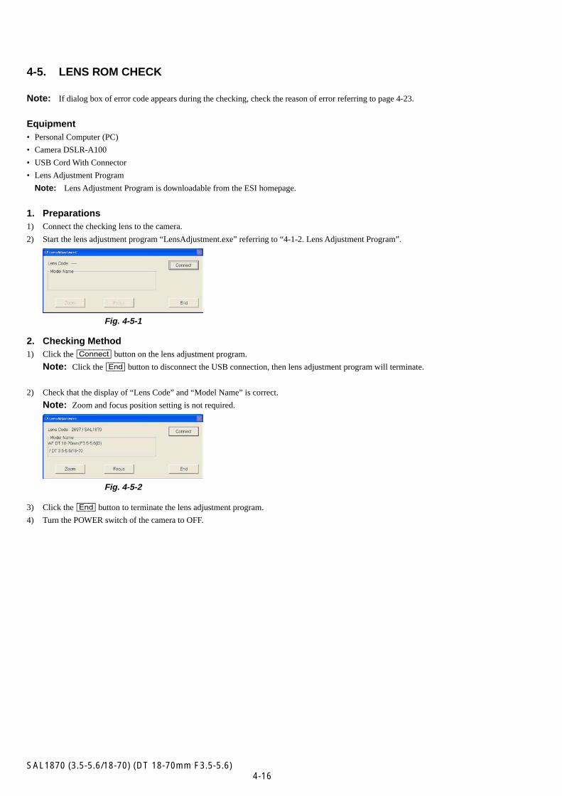
2) Start the lens adjustment program “LensAdjustment.exe” referring to “4-1-2. Lens Adjustment Program”.
Fig. 4-5-1
2. Checking Method1) Click the [Connect] button on the lens adjustment program.
Note: Click the [End] button to disconnect the USB connection, then lens adjustment program will terminate.
2) Check that the display of “Lens Code” and “Model Name” is correct.
Note: Zoom and focus position setting is not required.
Fig. 4-5-2
3) Click the [End] button to terminate the lens adjustment program.
4) Turn the POWER switch of the camera to OFF.
4-17SAL1870 (3.5-5.6/18-70) (DT 18-70mm F3.5-5.6)
4-6. ZOOM BRUSH POSITION CHECK/ADJUSTMENT AND PATTERN CHECK
Note: If dialog box of error code appears during the checking or adjustment, check the reason of error referring to page 4-23.
4-6-1. Zoom Brush Position Check
Equipment• Personal Computer (PC)
• Camera DSLR-A100
• USB Cord With Connector
• Lens Adjustment Program
Note: Lens Adjustment Program is downloadable from the ESI homepage.
1. Preparations1) Connect the checking lens to the camera.
2) Start the lens adjustment program “LensAdjustment.exe” referring to “4-1-2. Lens Adjustment Program”.
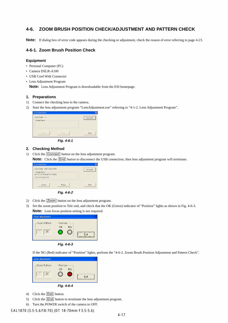
Fig. 4-6-1
2. Checking Method1) Click the [Connect] button on the lens adjustment program.
Note: Click the [End] button to disconnect the USB connection, then lens adjustment program will terminate.
Fig. 4-6-2
2) Click the [Zoom] button on the lens adjustment program.
3) Set the zoom position to Tele end, and check that the OK (Green) indicator of “Position” lights as shown in Fig. 4-6-3.
Note: Lens focus position setting is not required.
Fig. 4-6-3
If the NG (Red) indicator of “Position” lights, perform the “4-6-2. Zoom Brush Position Adjustment and Pattern Check”.
Fig. 4-6-4
4) Click the [Exit] button.
5) Click the [End] button to terminate the lens adjustment program.
6) Turn the POWER switch of the camera to OFF.
4-18SAL1870 (3.5-5.6/18-70) (DT 18-70mm F3.5-5.6)
4-6-2. Zoom Brush Position Adjustment and Pattern Check
Equipment• Personal Computer (PC)
• Camera DSLR-A100
• USB Cord With Connector
• Lens Adjustment Program
Note: Lens Adjustment Program is downloadable from the ESI homepage.
• Zoom Barrel Holder Jig
Note: For details of the jig making method, refer to “4-1-1. List of Service Tools and Equipments”.
1. Preparations1) Attach the zoom barrel holder jig to the checking lens and assemble the lens.
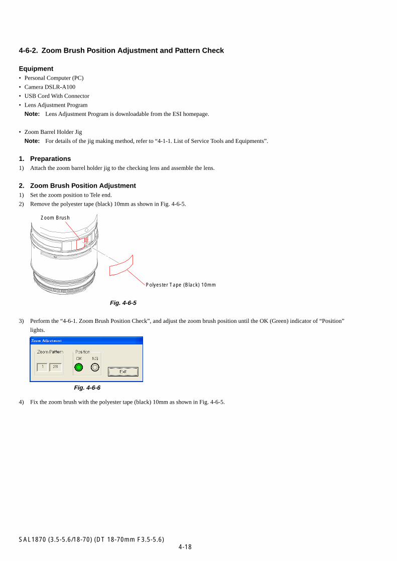
2. Zoom Brush Position Adjustment1) Set the zoom position to Tele end.
2) Remove the polyester tape (black) 10mm as shown in Fig. 4-6-5.
Fig. 4-6-5
3) Perform the “4-6-1. Zoom Brush Position Check”, and adjust the zoom brush position until the OK (Green) indicator of “Position”
lights.
Fig. 4-6-6
4) Fix the zoom brush with the polyester tape (black) 10mm as shown in Fig. 4-6-5.
Zoom Brush
Polyester Tape (Black) 10mm
4-19SAL1870 (3.5-5.6/18-70) (DT 18-70mm F3.5-5.6)
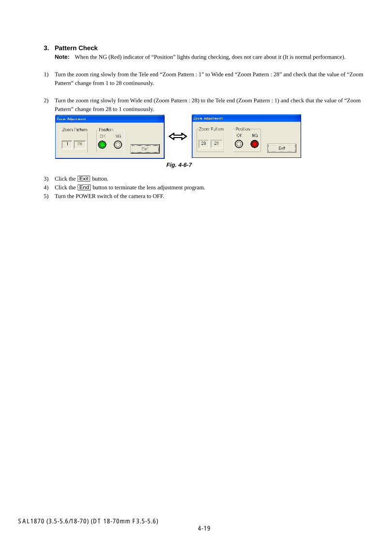
3. Pattern CheckNote: When the NG (Red) indicator of “Position” lights during checking, does not care about it (It is normal performance).
1) Turn the zoom ring slowly from the Tele end “Zoom Pattern : 1” to Wide end “Zoom Pattern : 28” and check that the value of “Zoom
Pattern” change from 1 to 28 continuously.
2) Turn the zoom ring slowly from Wide end (Zoom Pattern : 28) to the Tele end (Zoom Pattern : 1) and check that the value of “Zoom
Pattern” change from 28 to 1 continuously.
Fig. 4-6-7
3) Click the [Exit] button.
4) Click the [End] button to terminate the lens adjustment program.
5) Turn the POWER switch of the camera to OFF.
hhhhh
4-20SAL1870 (3.5-5.6/18-70) (DT 18-70mm F3.5-5.6)
4-7. FOCUS BRUSH POSITION CHECK/ADJUSTMENT AND PATTERN CHECK
Note: If dialog box of error code appears during the checking or adjustment, check the reason of error referring to page 4-23.
4-7-1. Focus Brush Position Check
Equipment• Personal Computer (PC)
• Camera DSLR-A100
• USB Cord With Connector
• Lens Adjustment Program
Note: Lens Adjustment Program is downloadable from the ESI homepage.
1. Preparations1) Connect the checking lens to the camera.
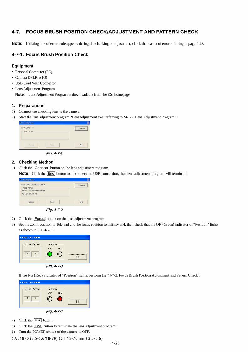
2) Start the lens adjustment program “LensAdjustment.exe” referring to “4-1-2. Lens Adjustment Program”.
Fig. 4-7-1
2. Checking Method1) Click the [Connect] button on the lens adjustment program.
Note: Click the [End] button to disconnect the USB connection, then lens adjustment program will terminate.
Fig. 4-7-2
2) Click the [Focus] button on the lens adjustment program.
3) Set the zoom position to Tele end and the focus position to infinity end, then check that the OK (Green) indicator of “Position” lights
as shown in Fig. 4-7-3.
Fig. 4-7-3
If the NG (Red) indicator of “Position” lights, perform the “4-7-2. Focus Brush Position Adjustment and Pattern Check”.
Fig. 4-7-4
4) Click the [Exit] button.
5) Click the [End] button to terminate the lens adjustment program.
6) Turn the POWER switch of the camera to OFF.

4-21SAL1870 (3.5-5.6/18-70) (DT 18-70mm F3.5-5.6)
4-7-2. Focus Brush Position Adjustment and Pattern Check
Equipment• Personal Computer (PC)
• Camera DSLR-A100
• USB Cord With Connector
• Adhesive bond (B-10)
• Lens Adjustment Program
Note: Lens Adjustment Program is downloadable from the ESI homepage.
• Zoom Barrel Holder Jig
Note: For details of the jig making method, refer to “4-1-1. List of Service Tools and Equipments”.
1. Preparations1) Attach the zoom barrel holder jig to the checking lens and assemble the lens.
2. Focus Brush Position Adjustment1) Set the focus position to infinity end.
2) Loosen the two screws fixing the focus brush.
Fig. 4-7-5
3) Perform the “4-7-1. Focus Brush Position Check”, and adjust the focus brush position until the OK (Green) indicator of “Position”
lights.
Fig. 4-7-6
4) Tighten the two screws loosened in step 2).
Two screws
Focus Brush
4-22SAL1870 (3.5-5.6/18-70) (DT 18-70mm F3.5-5.6)
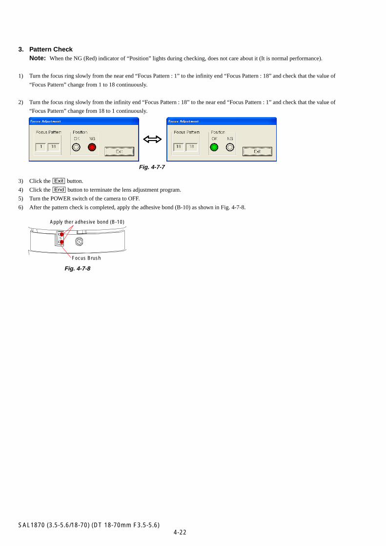
3. Pattern CheckNote: When the NG (Red) indicator of “Position” lights during checking, does not care about it (It is normal performance).
1) Turn the focus ring slowly from the near end “Focus Pattern : 1” to the infinity end “Focus Pattern : 18” and check that the value of
“Focus Pattern” change from 1 to 18 continuously.
2) Turn the focus ring slowly from the infinity end “Focus Pattern : 18” to the near end “Focus Pattern : 1” and check that the value of
“Focus Pattern” change from 18 to 1 continuously.
Fig. 4-7-7
3) Click the [Exit] button.
4) Click the [End] button to terminate the lens adjustment program.
5) Turn the POWER switch of the camera to OFF.
6) After the pattern check is completed, apply the adhesive bond (B-10) as shown in Fig. 4-7-8.
Fig. 4-7-8
hhhhh
Focus Brush
Apply ther adhesive bond (B-10)
4-23SAL1870 (3.5-5.6/18-70) (DT 18-70mm F3.5-5.6)
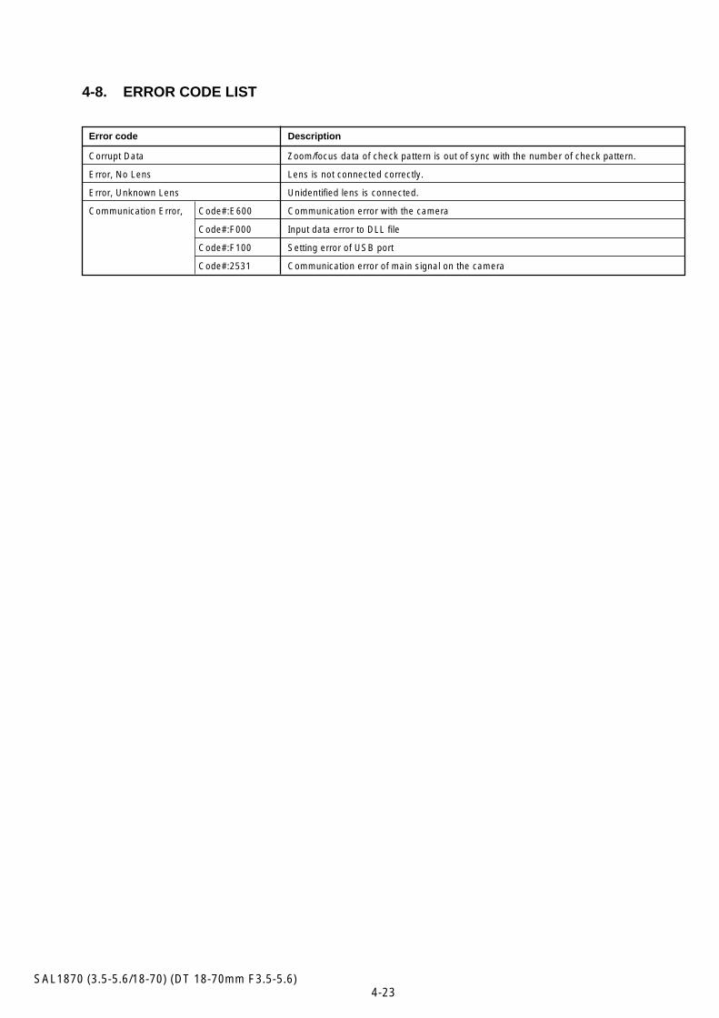
4-8. ERROR CODE LIST
Error code Description
Corrupt Data Zoom/focus data of check pattern is out of sync with the number of check pattern.
Error, No Lens Lens is not connected correctly.
Error, Unknown Lens Unidentified lens is connected.
Communication Error, Code#:E600 Communication error with the camera
Code#:F000 Input data error to DLL file
Code#:F100 Setting error of USB port
Code#:2531 Communication error of main signal on the camera
SERVICE MANUAL
SAL1870 (3.5-5.6/18-70) (DT 18-70mm F3.5-5.6)
Ver. 1.3 2007.08
Sony EMCS Co.2007H0800-1
© 2007. 08Published by Kohda TEC
US ModelCanadian Model
AEP ModelChinese Model
SUPPLEMENT-1File this supplement with the service manual.
(DI07-053)
• Addition of Repair Parts• Correction of error in writing
9-876-947-82
SAL1870(3.5-5.6/18-70) (DT 18-70mm F3.5-5.6)
Page
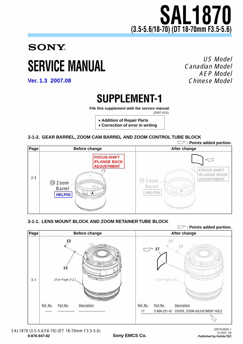
2-1-2. GEAR BARREL, ZOOM CAM BARREL AND ZOOM CONTROL TUBE BLOCK
Before change After change
2-3
& : Points added portion.
HELP05
0 ZoomBarrel
FOCUS-SHIFT/FLANGE BACKADJUSTMENT
HELP05
0 ZoomBarrel
FOCUS-SHIFT/FLANGE BACKADJUSTMENT
3-1-1. LENS MOUNT BLOCK AND ZOOM RETAINER TUBE BLOCK& : Points added portion.
Page Before change After change
3-1 (See Page 3-2.)
12
13
(See Page 3-2.)
12
1713
Ref. No. Part No. Description
—— ————— ————————
Ref. No. Part No. Description
17 2-898-231-01 COVER, ZOOM ADJUSTMENT HOLE
)
— 2 —SAL1870 (3.5-5.6/18-70) (DT 18-70mm F3.5-5.6)
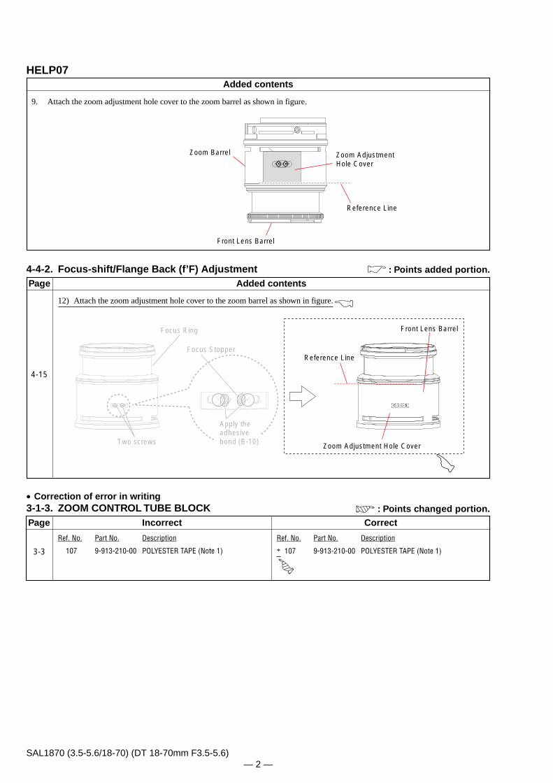
HELP07
4-4-2. Focus-shift/Flange Back (f’F) Adjustment
Zoom Barrel Zoom AdjustmentHole Cover
Reference Line
Front Lens Barrel
Zoom Adjustment Hole Cover
Reference Line
Front Lens Barrel
Apply the adhesive bond (B-10)Two screws
Focus Ring
Focus Stopper
9. Attach the zoom adjustment hole cover to the zoom barrel as shown in figure.
12) Attach the zoom adjustment hole cover to the zoom barrel as shown in figure.*
Page
• Correction of error in writing3-1-3. ZOOM CONTROL TUBE BLOCK
Ref. No. Part No. Description
107 9-913-210-00 POLYESTER TAPE (Note 1)
Ref. No. Part No. Description
* 107 9-913-210-00 POLYESTER TAPE (Note 1)
Incorrect Correct
3-3
: Points changed portion.
Added contents
Added contents
& : Points added portion.
Page
4-15
SERVICE MANUAL
SAL1870 (3.5-5.6/18-70) (DT 18-70mm F3.5-5.6)
Ver. 1.5 2008.04
Sony EMCS Co.2008D0800-1
© 2008. 04Published by Kohda TEC
US ModelCanadian Model
AEP ModelChinese Model
SUPPLEMENT-2File this supplement with the service manual.
(DI08-032)
9-876-947-84
SAL1870(3.5-5.6/18-70) (DT 18-70mm F3.5-5.6)
Page
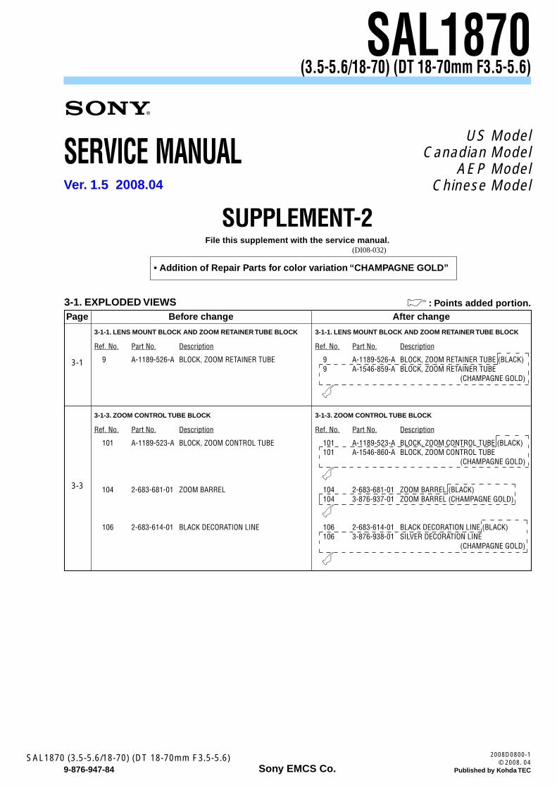
3-1. EXPLODED VIEWSBefore change After change
3-1
& : Points added portion.
• Addition of Repair Parts for color variation “CHAMPAGNE GOLD”
3-1-1. LENS MOUNT BLOCK AND ZOOM RETAINER TUBE BLOCK 3-1-1. LENS MOUNT BLOCK AND ZOOM RETAINER TUBE BLOCK
Ref. No. Part No. Description Ref. No. Part No. Description
9 A-1189-526-A BLOCK, ZOOM RETAINER TUBE 9 A-1189-526-A BLOCK, ZOOM RETAINER TUBE (BLACK)9 A-1546-859-A BLOCK, ZOOM RETAINER TUBE
(CHAMPAGNE GOLD)
(
3-3
3-1-3. ZOOM CONTROL TUBE BLOCK 3-1-3. ZOOM CONTROL TUBE BLOCK
Ref. No. Part No. Description Ref. No. Part No. Description
101 A-1189-523-A BLOCK, ZOOM CONTROL TUBE
104 2-683-681-01 ZOOM BARREL
106 2-683-614-01 BLACK DECORATION LINE
101 A-1189-523-A BLOCK, ZOOM CONTROL TUBE (BLACK)101 A-1546-860-A BLOCK, ZOOM CONTROL TUBE
(CHAMPAGNE GOLD)
104 2-683-681-01 ZOOM BARREL (BLACK)104 3-876-937-01 ZOOM BARREL (CHAMPAGNE GOLD)
106 2-683-614-01 BLACK DECORATION LINE (BLACK)106 3-876-938-01 SILVER DECORATION LINE
(CHAMPAGNE GOLD)
(
(
(
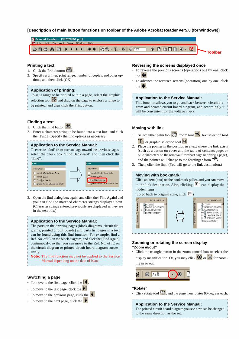
[Description of main button functions on toolbar of the Adobe Acrobat Reader Ver5.0 (for Windows)]
Printing a text1. Click the Print button .2. Specify a printer, print range, number of copies, and other op-
tions, and then click [OK].
Application of printing:To set a range to be printed within a page, select the graphic
selection tool and drag on the page to enclose a range tobe printed, and then click the Print button.
Finding a text1. Click the Find button .2. Enter a character string to be found into a text box, and click
the [Find]. (Specify the find options as necessary)
Application to the Service Manual:To execute “find” from current page toward the previous pages,select the check box “Find Backward” and then click the“Find”.
3. Open the find dialog box again, and click the [Find Again] andyou can find the matched character strings displayed next.(Character strings entered previously are displayed as they arein the text box.)
Application to the Service Manual:The parts on the drawing pages (block diagrams, circuit dia-grams, printed circuit boards) and parts list pages in a textcan be found using this find function. For example, find aRef. No. of IC on the block diagram, and click the [Find Again]continuously, so that you can move to the Ref. No. of IC onthe circuit diagram or printed circuit board diagram succes-sively.Note: The find function may not be applied to the Service
Manual depending on the date of issue.
Switching a page• To move to the first page, click the .
• To move to the last page, click the .
• To move to the previous page, click the .
• To move to the next page, click the .
Reversing the screens displayed once• To reverse the previous screens (operation) one by one, click
the .
• To advance the reversed screens (operation) one by one, click
the .
Application to the Service Manual:This function allows you to go and back between circuit dia-gram and printed circuit board diagram, and accordingly itwill be convenient for the voltage check.
Moving with link
1. Select either palm tool , zoom tool , text selection tool
, or graphic selection tool .2. Place the pointer in the position in a text where the link exists
(such as a button on cover and the table of contents page, orblue characters on the removal flowchart page or drawing page),and the pointer will change to the forefinger form .
3. Then, click the link. (You will go to the link destination.)
Moving with bookmark:Click an item (text) on the bookmark pallet, and you can moveto the link destination. Also, clicking can display thehidden items.(To go back to original state, click )
Zooming or rotating the screen display“Zoom in/out”• Click the triangle button in the zoom control box to select the
display magnification. Or, you may click or for zoom-
ing in or out.
“Rotate”• Click rotate tool , and the page then rotates 90 degrees each.
Application to the Service Manual:The printed circuit board diagram you see now can be changedto the same direction as the set.
Toolbar
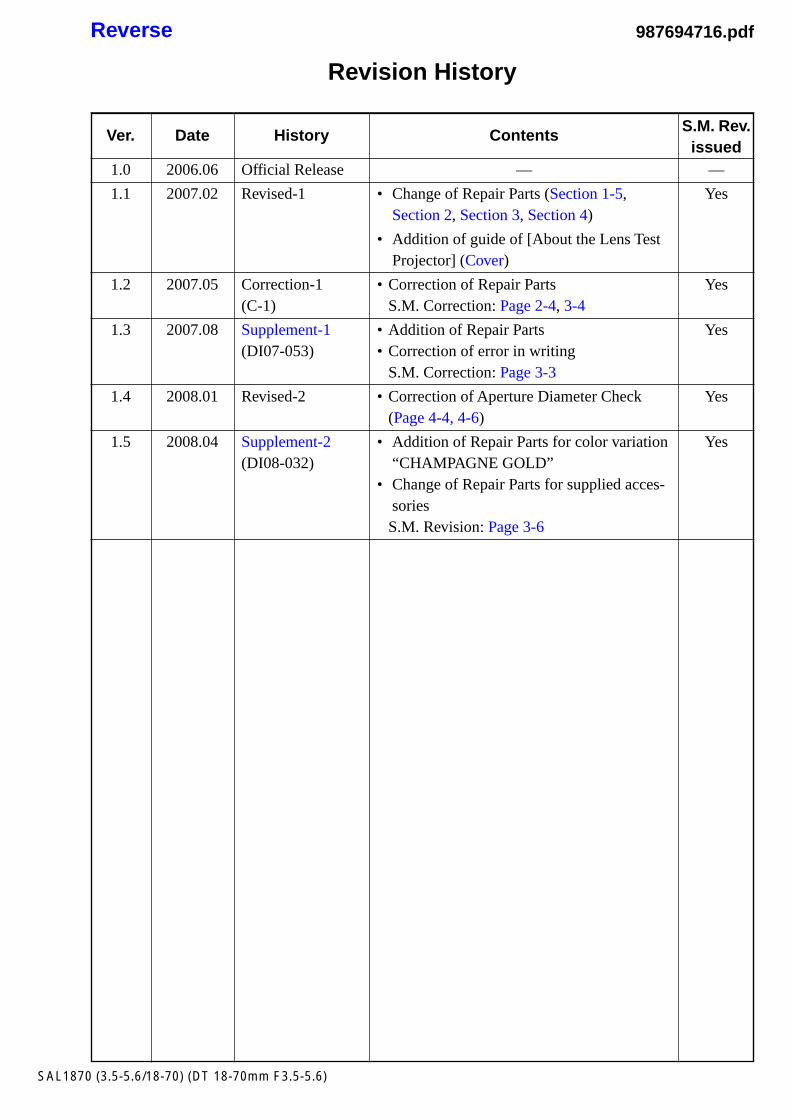
Revision History
Reverse
SAL1870 (3.5-5.6/18-70) (DT 18-70mm F3.5-5.6)
Ver.
1.0
1.1
1.2
1.3
1.4
1.5
Date
2006.06
2007.02
2007.05
2007.08
2008.01
2008.04
History
Official Release
Revised-1
Correction-1(C-1)
Supplement-1(DI07-053)
Revised-2
Supplement-2(DI08-032)
Contents
—
• Change of Repair Parts (Section 1-5,Section 2, Section 3, Section 4)
• Addition of guide of [About the Lens TestProjector] (Cover)
• Correction of Repair PartsS.M. Correction: Page 2-4, 3-4
• Addition of Repair Parts• Correction of error in writing
S.M. Correction: Page 3-3
• Correction of Aperture Diameter Check(Page 4-4, 4-6)
• Addition of Repair Parts for color variation“CHAMPAGNE GOLD”
• Change of Repair Parts for supplied acces-soriesS.M. Revision: Page 3-6
S.M. Rev.issued
—
Yes
Yes
Yes
Yes
Yes
987694716.pdf