Embed Size (px)
Citation preview

Saitel DP
M57800000y / SM_CPU866e
User Manual This manual provides information for the assembly, wiring, configuration and maintenance of the SM_CPU866e module.
SE-USR-M578
Publication Date (10/2019)
Read carefully the information contained in this manual before assembly, installation and use of the equipment.
www.schneider-electric.com

09/10/2019 User Manual – SM_CPU866e
Pag 2 R&D Digital Seville
Change Control
Rev Date Description
01 09-10-2019 Initial edition
General Information The Saitel platform and all its components have been developed in accordance to the requirements for a quality management system, complying with the ISO 9001:2015 Norm.
Document nº: SE-USR-M578
Revision/Date: 01 / 09-10-2019
File: SM_CPU866e – User Manual_EN_01.pdf
Retention period: Permanent throughout its validation period + 3 years after its cancellation.
Reference Documents
User Manual Document Code
Easergy Builder User Manual FTE-MSS-S856
webApp User Manual FTE-WPP-S856
EOL Instructions FTE-EOLI-M578
Application note AN010 (Mounting a Saitel DP module in a backplane)
FTE-AN010-F700
Software Version in this Manual The information in this manual is valid for the software versions listed below. This information is also valid for later versions, although some parameters may change slightly:
Module RTU Software Easergy Builder (Plugin)
Module Version Plugin Version
Baseline 11.06.12
Linux Lnx 19.06.24.12.22.30
Easergy Builder Tool 1.4.7
Local Acquisition laqBinC 10.00.02 LAQ 01.02.00
Synchronization thm 06.00.00
coreDb coreDb 10.01.10
Channels chan 03.00.19
Cybersecurity Brick CSBrick 02.03.00.05
BLMon BLMon 01.01.04
Formula formBinC 10.00.13

User Manual – SM_CPU866e 09/10/2019
R&D Digital Seville Pag 3
Web Server (webApp) webServer 03.03.02
Supervision sup 10.01.19

09/10/2019 User Manual – SM_CPU866e
Pag 4 R&D Digital Seville
Content
1 SAFETY & HEALTH .................................................................................................. 5
2 GENERAL DESCRIPTION ...................................................................................... 16
3 PHYSICAL MOUNTING & INSTALLING ................................................................ 28
4 CONFIGURATION & MAINTENANCE .................................................................... 46
5 EASERGY BUILDER ............................................................................................... 63
6 ADVANCED OPERATIONS .................................................................................... 86
7 TECHNICAL SPECIFICATIONS TABLE .............................................................. 101

User Manual – SM_CPU866e 09/10/2019
R&D Digital Seville Pag 5
1 Safety & Health
09/10/2019 User Manual – SM_CPU866e
Pag 6 R&D Digital Seville
Content
1 SAFETY & HEALTH .................................................................................................. 5
1.1 INTRODUCTION ........................................................................................................ 7 1.1.1 INFORMATION OF SECURITY .............................................................................. 7 1.1.2 PRESENTATION ................................................................................................ 7
1.2 INTRODUCTION TO SAFETY ....................................................................................... 8 1.3 SYMBOLS AND LABELS ON THE EQUIPMENT ............................................................. 9 1.4 INSTALLATION, SETUP AND OPERATION ................................................................... 9 1.5 EARTHING ............................................................................................................. 11
1.5.1 ELECTRICAL SAFETY ...................................................................................... 11 1.5.2 FUNCTIONAL EARTH (EMC) ............................................................................ 12
1.6 HANDLING ELECTRONIC COMPONENTS .................................................................. 12 1.7 TECHNICAL SPECIFICATIONS FOR SAFETY .............................................................. 13
1.7.1 PROTECTIVE ELEMENTS ................................................................................. 13 1.7.2 ENVIRONMENTAL CONDITIONS ........................................................................ 13 1.7.3 STORAGE CONDITIONS ................................................................................... 13
1.8 TECHNICAL LABEL ................................................................................................. 14 1.9 PACKING AND UNPACKING ..................................................................................... 14 1.10 DECOMMISSIONING AND DISPOSAL ....................................................................... 14 1.11 NORMS AND STANDARDS / CE MARK ................................................................... 15

User Manual – SM_CPU866e 09/10/2019
R&D Digital Seville Pag 7
1.1 Introduction 1.1.1 Information of Security
Important information Read these instructions carefully and look at the equipment to become familiar with the device before trying to install, operate, service or maintain it. In this manual you can find different types of messages associated with situations that have different level of risk for people and / or for the equipment.
This symbol indicates "DANGER" or "WARNING". This symbol informs of an electrical risk that will cause personal injuries if the instructions are not followed.
This symbol is associated to a safety alert. It is used to warn of possible personal injury hazards. The user must follow all instructions or messages associated to this symbol to avoid possible injuries.
DANGER DANGER indicates a hazardous situation which, if not avoided, will result in death or serious injury.
WARNING WARNING indicates a hazardous situation which, if not avoided, could result in death or serious injury.
NOTICE NOTICE is used to address practices not related to physical injury. The safety alert symbol shall not be used with this signal word.
To Keep in Mind Electrical equipment should be installed, operated, serviced, and maintained only by qualified personnel. No responsibility is assumed by Schneider Electric for any consequences arising out of the use of this material.
A qualified person is who fulfil with requirements in paragraph 1.2 1.2 .
1.1.2 Presentation This manual provides information for a safe handling, commissioning and testing. This Safety chapter also includes descriptions of the labels on the equipment.
Documentation for equipment ordered from Schneider Electric is dispatched separately from manufactured goods and may not be received at the same time. Therefore, this guide is provided to ensure that printed information which may be present on the equipment is fully understood by the recipient.

09/10/2019 User Manual – SM_CPU866e
Pag 8 R&D Digital Seville
The technical data in this safety guide is typical only, see the technical data section of the user manual for specific details of a particular equipment.
Before carrying out any work on the equipment the user should be familiar with the contents of this Safety chapter and the ratings on the equipment’s rating label.
THE SAFETY SECTION MUST BE READ BEFORE STARTING ANY WORK ON THE EQUIPMENT.
1.2 Introduction to Safety The information in the Safety Section of the equipment documentation is intended to ensure that equipment is properly installed and handled in order to maintain it in a safe condition. It is assumed that everyone who will be associated with the equipment will be familiar with the contents of that Safety Section, or this manual.
When electrical equipment is in operation, dangerous voltages will be present in certain parts of the equipment. Failure to observe warning notices, incorrect use, or improper use may endanger personnel and equipment and also cause personal injury or physical damage.
WARNING Before working with the terminal of connection, the device must be turned off and disconnected of the feeding.
Proper and safe operation of the equipment depends on appropriate shipping and handling, proper storage, installation and commissioning, and on careful operation, maintenance and servicing. For this reason, only qualified personnel may work on or operate the equipment.
Qualified personnel are individuals who:
• Are familiar with the installation, commissioning, and operation of the equipment and of the system to which it is being connected.
• Are able to safely perform switching operations in accordance with accepted safety engineering practices and are authorized to energize and de-energize equipment and to isolate, ground, and label it.
• Are trained in the care and use of safety apparatus in accordance with safety engineering practices.
• Are trained in emergency procedures (first aid).
It is necessary to consider that the documentation of the device collects the instructions for its installation, set up and operation. However, the manuals could not cover all the possible circumstances neither include specific information on all the details.
In case of questions or specific problems, contact with his sales office of Schneider Electric or with the customer care center and request the necessary information.

User Manual – SM_CPU866e 09/10/2019
R&D Digital Seville Pag 9
1.3 Symbols and Labels on the Equipment Before the equipment is installed or commissioned, the user must understand the following symbols, which may be used on the equipment or referred to in the user documentation.
Table 1 – Symbols
Symbol Associated Text Description
Possibility of electric chock IEC symbol associated to a DANGER or WARNING message indicating that there is an electrical risk. Failure to follow these instructions could cause damage to people or death.
Caution, read the manual. Symbol associated with a risk alert. The user must read the manual before handling the equipment.
Possibility of electric chock
ANSY symbol associated to a DANGER or WARNING message indicating that there is an electrical risk. Failure to follow these instructions could cause damage to people or death.
Protective earth connection
Associated symbol to the protective ground connection. See paragraph 1.5.1 in this manual.
CE Mark This symbol indicates that the equipment has been developed in compliance with all applicable European Directives.
Electronic device. Special instructions must be follow for discard it.
This symbol indicates that, at the end of its life, this module must be discarded according to the WEEE Directive (Waste Electrical and Electronic Equipment).
Compliant with RoHS.
The equipment has been designed and manufactured according to RoHS Directive (Restriction of Hazardous Substances).
Direct Voltage Symbol of direct voltage (VDC).
Alternate Voltage Symbol of alternate voltage (VAC).
1.4 Installation, Setup and Operation There are several acquisition blocks in Saitel DP that use dangerous tensions (> 50 V). The user is responsible to check that the characteristics of each device are adapted and convenient for his installation. The user should read the instructions of installation before proceeding to the use or maintenance of the devices. Not following these instructions can be dangerous for the people and the devices.
Not following these instructions can be dangerous for the people and the devices.
DANGER Devices that handle dangerous tensions are marked with a sticker on the front label (size: 12,5 mm). This label must be visible all the time while the module is installed on the backplane.

09/10/2019 User Manual – SM_CPU866e
Pag 10 R&D Digital Seville
The following products handle dangerous tensions:
• SM_DI32: Digital inputs module (P/N: M583x0000x).
• SM_PS40: Power supply module (P/N M5084x000x and M5085x000x).
• SM_PS: Power supply module (P/N M5155x000x).
• SM_DO16R and SM_DO32T: These modules do not handle high voltages, they will not be marked at the factory. These modules must be marked to inform about the risk when some equipment that manage voltage higher than 50 V are connected to digital outputs.
It is recommended to install the RTU inside a cabinet with a key. This cabinet only should be opened by a qualified person.
WARNING If this type of cabinet isn't available, a barrier must be installed in order to avoid an accidental contact with these dangerous elements. This barrier only should can be removed using a special tool.
If the barrier has to be removed in order to access to equipment, personnel responsible for the task must be sure that the barrier is installed again when the task is finished.
While the RTU is accessible for a user, all people must follow all instructions to prevent electrical risk or discharges.
Not following these instructions can give like result that the device do not work properly or even can damage to the people or devices.
An electrical risk symbol with enough size must be included on the cabinet’s door or on the barrier.
The following image shows an example:
Figure 1 - Barrier of protection for elements with dangerous voltages.
NOTICE Terminals will not be accessible to the user directly once it has made the installation of the device. The cabinet will have to remain closed with key or the screen of installed protection.
The cabinet or installation must have a general switch placed just in the cable entry of the installation (see paragraph 1.7.1 )
For the cleaning of the equipment, it is recommended to remove the power and to use only a dry cloth by the surface when it detects excessive presence of dust or any element deposited on the surface.

User Manual – SM_CPU866e 09/10/2019
R&D Digital Seville Pag 11
WARNING Don’t use liquid products of cleanliness due to the presence of active parts.
Because of the variety of uses of the product, the managers of the application and use of this device of control will have to take the measures to ensure the fulfilment of all the requests of security and provision of each application. The requests do reference to the applicable laws, regulations, codes and standard.
1.5 Earthing WARNING
Before energizer the device, it has to be placed to earth properly such as it indicates in sections 1.5.1 and 1.5.2 . When installing the device, ground is the first thing that should be connected and the last one that should be disconnected.
Saitel can need put to earth for two distinct needs:
• For purposes of electrical safety (Protective Earth, PE).
• Improve the behaviour in Electromagnetic Compatibility (EMC) and derive perturbations to earth (functional Earth).
1.5.1 Electrical Safety Only qualified personnel, with knowledge about hazards associate with electrical equipment is allowed to install Saitel DP. In general, the installation will be following IEC 61010-1 recommendations in order to be compliant with this norm.
When Saitel DP is mounted on back-panel, the backplane on is metallic enclosure must be installed on a metallic surface. This surface must be connected to the ground of the cabinet or installation according to the norm IEC 61010-1. When Saitel DP is mounted on a chassis, this chassis must be connected to the ground of the installation.
Saitel DP modules have a plastic enclosure offering protection for isolation faults. Earthing
WARNING All devices with high voltage must be disconnected before dismount a module.
A dedicated connection with green/yellow wire should be used to assure electric continuity to the installation protective earth. Section of these wires must be enough in order to support 25 A (ground bonding test).
Figure 2 - Yellow and Green cable for earthing.

09/10/2019 User Manual – SM_CPU866e
Pag 12 R&D Digital Seville
The design and installation of the cabinet is responsible for compliance with all the existing international and national electrical codes concerning protective grounding of any device.
WARNING According to Electrical Safety:
• The screw for ground must be exclusive for this use. • The power voltage must be supplied by a power supply that offers double or reinforced
insulation against dangerous voltages.
1.5.2 Functional Earth (EMC) The available rear connector on each module allows the bus connection and it offers protection in case of electric derive. The EMC grounding is implemented via three pins of this connector.
WARNING Never connect modules on the backplanes if the power supply hasn’t been disconnected of all circuits with high voltages.
The only modules with a ground connection are the power supplies (SM_PS and SM_PS40). Both must be connected to the ground of the cabinet.
1.6 Handling Electronic Components Like any electronic device, Saitel is susceptible to receive electrostatic discharges during the handling. It is necessary to take the usual measures to minimize this risk, since serious damage to the equipment can be caused, which may not be detected immediately but which may affect the reliability of the product.
WARNING The enclosure ONLY should be removed when is strictly necessary, because this action has a risk for the equipment:
• Before removing the enclosure, the operator must be equipotential with the equipment.
• Avoid touching the electronic. The board must be always manipulated for the edges.
• If the equipment has to be passed between two persons, both must be equipotential.
• Put the module always on an antistatic surface or on a surface equipotential with you.
• During the storage and transport, the module will remain in the packaging.
Not following these instructions can give like result that the device do not work properly or even can damage to the people or devices.

User Manual – SM_CPU866e 09/10/2019
R&D Digital Seville Pag 13
1.7 Technical Specifications for Safety 1.7.1 Protective Elements
The cabinet's engineering and installation must include a general automatic switch next to the cables' input in the cabinet; once the door is opened, high voltages must be interrupted inside. This switch must be located at a place which is not accessible by a third person while the operator is using the boards in the cabinet.
Moreover, the installation will incorporate a circuit breaker of 5A next to the cabinet protecting it from possible overcurrent in the power supply.
Both switches will be labelled with the symbol O as "Off" and I as “On”.
WARNING The connection / disconnection switch must be installed in a fixed element (for example the wall of the cabinet) and it mustn’t break any earthing wire.
1.7.2 Environmental Conditions The protection degree of the device is IP20. It is designed only for his use in interiors. If it is necessary for his use in some external surroundings, it has to mount in a cabinet or specific accommodation that contributes a degree of protection IP54, protected against the dust and water.
The electronic cards of the modules will be able to be tropicalized or no according to the option of setting chosen. The tropicalized used is the AVR80, of the company ABchimie. It can consult all the technical information of this type of finishing in http://www.abchimie.com/.
Other data to consider about the environmental are:
• Altitude until 2000 m.
• Operation temperature range: Between -40 ºC and 70 ºC. (IEC 60068-2-1 and IEC 60068-2-2).
• Maximum relative humidity of 95%. (IEC 60068-2-30)
• Degree of pollution II. (IEC 60255-5)
• Overvoltage transitory until levels of Category III. (IEC 60255-5)
1.7.3 Storage Conditions The continuous exhibition to some high levels of humidity during the storage can cause damages to the electronic components and reduce the useful life of the device.
We recommend that, in the enclosure of storage, the relative humidity do not exceed 50%.
Before the installation of an electrical equipment, it is recommended to leave the necessary time for the acclimatization of the environmental temperature.

09/10/2019 User Manual – SM_CPU866e
Pag 14 R&D Digital Seville
1.8 Technical Label Each Saitel product includes a technical label with the following information:
Figure 3 - Technical label.
NOTICE On the “Technical data” zone, you can see relevant information about the input and output voltage in the module. Any voltage greater than 50 V must be consider as a high voltage.
1.9 Packing and Unpacking All Saitel modules are packaged separately in their own carton box and shipped inside outer packaging. Use special care when unpacking the device. Don’t use force.
The design revision and manufacturing options can be determined using the P/N included in the packaging label on packaging.
After unpacking the device, inspect it visually to be sure it is in proper mechanical condition.
If the product needs to be shipped, the original packaging must be used, including foams and the carton box. If the original packaging is no longer available, make sure that the packaging used is according to ISO 2248 specifications for a drop height 1 m.
1.10 Decommissioning and Disposal
SM_CPU866e is marked with this symbol, it means that, at the end of its life cycle, you mustn't dispose the product together with habitual residues. To avoid possible damage to the environment or to the human health that represents the uncontrolled elimination of residues, please follow the instructions in EOLI document for SM_CPU866e.
SM_CPU866e includes a Lithium battery NOT rechargeable. Please, take special care recycling this element.
WARNING Only a qualified person should change the battery when is necessary, and the same model of battery must be used. More information in the technical specifications table at the end of this manual.

User Manual – SM_CPU866e 09/10/2019
R&D Digital Seville Pag 15
1.11 Norms and Standards / CE Mark Saitel has been designed and manufactured in compliant with the following Directives:
• LVD: Low voltage directive (2014/35/UE).
• EMC: Electromagnetic Compatibility (2014/30/UE).
• RoHS 2: Restriction of Hazardous Substances (2011/65/EU).
• WEEE: Waste Electrical and Electronic Equipment directive (2012/19/UE)

09/10/2019 User Manual – SM_CPU866e
Pag 16 R&D Digital Seville
2 General Description

User Manual – SM_CPU866e 09/10/2019
R&D Digital Seville Pag 17
Content
2 GENERAL DESCRIPTION ...................................................................................... 16
2.1 GENERAL DESCRIPTION OF SAITEL DP ................................................................... 18 2.2 SAITEL DP MODULES ............................................................................................ 19
2.2.1 AVAILABLE MODULE TYPES ............................................................................ 19 2.3 INTERNAL ARCHITECTURE USING BACKPLANE ........................................................ 19 2.4 BASELINE SOFTWARE PLATFORM .......................................................................... 20
2.4.1 MAIN ELEMENTS ............................................................................................. 22 2.5 SM_CPU866E MODULE ........................................................................................ 23
2.5.1 OPERATION CONTROL .................................................................................... 23 2.5.2 RTU CONFIGURATION .................................................................................... 24 2.5.3 SYNCHRONIZATION ......................................................................................... 24 2.5.4 COMMUNICATIONS .......................................................................................... 24 2.5.5 I/O ACQUISITION ............................................................................................ 24 2.5.6 REAL TIME DATA BASE (COREDB) .................................................................... 25 2.5.7 CYBERSECURITY ............................................................................................ 25
2.6 LED INDICATORS ................................................................................................... 26

09/10/2019 User Manual – SM_CPU866e
Pag 18 R&D Digital Seville
2.1 General Description of Saitel DP The Saitel DP platform is a complete set of devices provided by Schneider Electric for real-time control applications and power line automation. It is a high-technology platform which gives a solution to the business areas of Schneider Electric.
The following figures show a Saitel DP in chassis (left) and in backplane (right).
Saitel DP’s design has been optimized to meet the most demanding requirements of multiple sectors:
• Cost-efficiency, minimum downtime, and compliance with electrical safety, electromagnetic compatibility and environmental standards.
• Safety and reliability requirements for power, gas, water, residual water supply, etc.
• Centralized monitoring and control of geographically-distributed systems which support hierarchical data acquisition and redundant networks.
• Local monitoring and control with data sharing capabilities of plant-distributed devices.
• Quick troubleshooting by means of programmable automation execution.
• One of the most remarkable features of Saitel DP is its modular design. All I/O, CPU, power supply and communication modules have an identical format, sharing the same enclosure.
Figure 4 - Saitel DP architecture
User Manual – SM_CPU866e 09/10/2019
R&D Digital Seville Pag 19
2.2 Saitel DP Modules The Saitel DP electronic modules have been designed to operate in aggressive industrial environments, complying with the highest standards, such as Electromagnetic compatibility (EMC). The low-consumption design allows modules to operate without a forced ventilation system, which creates a wide range of possible applications.
2.2.1 Available Module Types The set of modules making up the platform are:
• Control Units. The modules SM_CPU866 (using VxWorks OS) and SM_CPU866e (using Linux OS) are powerful CPU modules with abundant memory processing capabilities, Fast-Ethernet and fiber optic connections.
• Serial Communication Modules. SM_SER allows extend the communication capability of the CPU.
• Power Supply. There are two options:
o One or two SM_PS or SM_PS40 modules
o One or two external power supplies.
• I/O Modules. There is a wide range of I/O modules, for analog and digital signals: SM_DI32, SM_DO32T, SM_DO16R, SM_AI16 and SM_AI8AO4.
• Backplanes. This type of module is completely different from the modules described above, as its main purpose is to support the rest of the modules, by providing additional functions. There are two backplane models available: SM_BPX and SM_CHX, both available with 4 or 9 slots.
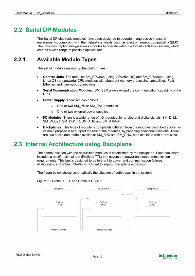
2.3 Internal Architecture using Backplane The communication with the acquisition modules is established by the backplane. Each backplane includes a multifunctional bus (Profibus TTL) that covers the power and intercommunication requirements. This bus is designed to be tolerant to power and communication failures. Additionally, a Profibus RS-485 is included to support backplane expansion.
The figure below shows schematically the situation of both buses in the system:
Figure 5 - Profibus TTL and Profibus RS-485

09/10/2019 User Manual – SM_CPU866e
Pag 20 R&D Digital Seville
These buses integrate the following bus lines:
• Profibus TTL: o PE - Protection ground. o PW1/2 – Power bus (primary and redundant). o PF1/2 (TTL) - Primary and redundant Profibus TTL buses. o MUX - Serial data bus for communications with the SM_SER module. o SYN (TTL) - Bus for synchronization for the modules. (Pulse Per Second or PPS). o SER - Serial bus for synchronization between redundant CPU modules.
• Profibus RS-485: o PF1/2 (485) - Primary and redundant Profibus RS-485 buses. o SYN (485) - Bus RS-485 for synchronization for the modules. (PPS).
The figure below shows the buses available in the backplane:
Figure 6 - Buses in a backplane
2.4 BaseLine Software Platform The BaseLine Software Platform of Schneider Electric consists of:
• Real-time operating system (RTOS): VxWorks (SM_CPU866) or Linux (SM_CPU866e).
• Real-time applications and configuration files (XML format).
• Software tools: Configuration, local and remote maintenance, supervision and monitorization.
The following figure shows the different applications included in the software platform, as well as additional applications (Devices) implementing new Devices or protocols to upgrade Easergy Builder:

User Manual – SM_CPU866e 09/10/2019
R&D Digital Seville Pag 21
Figure 7 - BaseLine Software Platform
The operating system abstracts the hardware from the software applications and manages the applications in real time. It integrates the basic protocols to access the remote unit (SFTP, SSH, etc.) and manage multiple users.
The real-time database, named coreDb, is probably the most important element. All the other elements are developed around coreDb.
Figure 8 - Relation between coreDb and other applications
coreDb performs the real-time management of RTU points. This real-time database is associated with data producing and consuming by device controllers.
The following concepts are related to coreDb:
• Device Controller (also referred to as Controller): Real-time application that accesses coreDb. Each Controller acts as a producer and/or consumer of information managed by coreDb.
• Point: Each register of coreDb is a point. A point can be included in the table Status, Analog, Command or Setpoint
• Device: A set of I/O points that share a common source/destination. A typical example of a Device is an IED that communicates with the RTU, or the representation of a SCADA

09/10/2019 User Manual – SM_CPU866e
Pag 22 R&D Digital Seville
exchanging information acquired or generated by the RTU. A Device is always associated to a type of Controller.
• Source: Origin of the value of a coreDb data point. Any coreDb data point can have several different sources (in one or several Devices). This means that a value of a database point can be configured to be updated by several different entities.
NOTICE It should be noted that any coreDb signal can be associated to more than one source; this is only applicable to Command and SetPoint tables. Allocating more than source to one point is not recommended in Status and Analog tables.
• Destination: Target of the value of a coreDb data point. coreDb data points can be configured to have several different destinations (in one or several Devices).
• Coordinate: Point identification within a Device. It is unique for each point and has a different structure for each Controller. It is described in detail in the appropriate manual of each Controller.
• Configuration Plugin: Specific Configuration plugins extend the Easergy Builder application to configure Device Controllers. Additional details about these plugins are provided further in this manual.
The user can modify the configuration of each Controller and Device using the appropriate Plugin. Once the database is completely configured, the files with the new information can be generated and transferred to the RTU, where they will be processed by the software on startup.
NOTICE The information exchange, that is, the exchange of configuration data between the RTU and Easergy Builder is not continuous but performed through XML files under user’s request. When the configuration is modified in Easergy Builder and the XML files are sent to the RTU, it is necessary to reboot the RTU.
2.4.1 Main Elements For the user’s point of view, the BaseLine Software Platform main elements are:
coreDb – Real Time DataBase (RTDB)
coreDb is the real-time database backend on which BaseLine Software Platform is built. All the information controlled and managed by the system is stored in this database.
Thanks to this architecture, the system’s functionalities can be easily expanded to manage new protocols, customized controllers, etc. To accomplish this, trained developers only need to implement the required Device Controller and the associated Configuration plugin for Easergy Builder, allowing end users to configure the extended functionality.
coreDb registers also are called data points or, simply points (this term will be used onwards to avoid confusing these with Device points). coreDb points are organized in four tables: Status, Analog, SetPoint and Command to group the different types of point. These internal tables present the following differences:
• Depending on the point type: Status, Command, and SetPoint points support integer values, whereas Analog signals manage floating values.
• Depending on the treatment of the point: Status and SetPoint points can be locked, reset to initial values, whereas the other two signal types cannot. All types can retain the value in a non-volatile memory.

User Manual – SM_CPU866e 09/10/2019
R&D Digital Seville Pag 23
Devices
Each type of device keeps a list of its associated points, identified by unique labels. These labels allow the identification of each device point unequivocally as source or destination of a coreDb data point.
Each point is a piece of information produced (or consumed) by a Device. Within a single Device, point identifiers (coordinates) are unique and cannot be used by two different points.
Software Tools
The user can use the following tools in order to access to the RTU information:
• Easergy Builder: Engineering tool for the RTU OFFLINE configuration. It allows to include and adapt the different functions of the RTU to the system where it is being integrated. It is a software tool that needs to be installed on a PC.
• CAE: Engineering tool for defining the security policy and assigning roles to users. It allows defining a series of rights and responsibilities in the system for authorized users. It defines WHO, WHAT, WHEN and HOW can the user do it, according to the RBAC model. It is a software tool that needs to be installed on a PC.
• webApp: Web tool for online maintenance and monitoring of the RTU. Using the configuration defined in Easergy Builder and loaded in the HUe, the user can consult and/or change some parameters through the WEB server. Unlike Easergy Builder, webApp does NOT allow adding new features. Only the parameters included in the configuration can be changed.
• Console: This tool should only be used by advanced users with a wide knowledge of the system. The connection can be made through a serial channel (PC’s COMx port) or using SSH through the maintenance Ethernet port (MNT). The console is a commands tool, which the user could execute or not depending on the level of privileges assigned to him.
2.5 SM_CPU866e Module The SM_CPU866e performs control functions for the complete equipment, by centralizing the information acquired by other system modules, and executing logical control programs, communication protocols and user-specific applications. The master CPU polls the slave modules in the chassis through two internal asynchronous serial communication channels at a speed of 1.5 Mbps. Every 2 ms the CPU polls the next slave module.
Following paragraphs explain the main features of the module SM_CPU866e.
2.5.1 Operation Control Controls the operation of itself, redundant CPU (if exits) and I/O modules connected to the CPU through the backplane.
These functions include:
• Operation mode monitoring. It performs functions as hardware and software Watchdog control, the state control of the I/O modules and the CPU and the provision of diagnostic information about the status through LED indicators and log files, which is accessible from the webApp or SFTP.
• Interface with the operator through the console and/or webApp Tool and Easergy Builder.
• Firmware upgrade via SFTP, webApp, USB or Ethernet port.

09/10/2019 User Manual – SM_CPU866e
Pag 24 R&D Digital Seville
2.5.2 RTU Configuration Generates information to create the real-time database in which I/O signals from the acquisition modules are associated to the communication protocols signals. The Easergy Builder Tool generates the configuration files (XML files) and are sent using a SFTP connection.
2.5.3 Synchronization Up to two different synchronization sources can be configured. In this configuration is included the priority level for each source, so there will be a primary and a secondary source. If both sources are active, only the primary source will synchronize the system.
NOTICE The primary source is used to synchronize the modules in the backplane, if available. Otherwise, the secondary source is used.
The available synchronization sources are:
• GPS: A GPS connected to the COM1 port. The time received from the GPS is used to set the system’s clock and the RTC.
• SNTP: An SNTP source through Ethernet. The SM_CPU866e module can operate as an SNTP client or as an SNTP server.
• Protocol: Most telecontrol protocols allow synchronizing to slave devices.
• PTP: IEEE® 1588 PTP support for synchronization by Ethernet.
• Console: The user can set the system's time manually from the console terminal.
• IRIG-B: Terminal for IRIG-B signal (standard 200-04, 002, 003, 006 and 007 codes).
If the synchronization source is not configured, the console device will always be created by default. The console operates as the lowest priority when another source is configured.
2.5.4 Communications The communication parameters are managed in this module, that supports the following protocols:
• IEC101 and IEC104, master and slave.
• DNP 3.0 master and slave.
• IEC103 master.
• Modbus master and slave.
• IEC61850 client, Edition 1 and 2.
• IEC61850 server, Edition 2.
2.5.5 I/O Acquisition This module manages the information exchange with the I/O modules. Its main functions include:
• Processing I/O information, which offers an added value to the information exchanged with the I/O modules.
• Accessing the internal bus (Profibus) to exchange information with the I/O modules.

User Manual – SM_CPU866e 09/10/2019
R&D Digital Seville Pag 25
2.5.6 Real time data base (coreDb) The RTDB is the real-time database which stores not only the information acquired from field devices, but also the information about the CPU and I/O modules connected with the backplane. The SM_CPU866e module uses the BaseLine Software Platform and therefore the real-time database is coreDb.
The RTDB also relates the acquisition signals to the communication protocol signals. This database is generated in the SM_CPU866e by using the configuration information.
The information which is received from field in real time is processed, stored in the RTDB and then related to the communication protocols signals of the backplane, which function is to transfer that information to the master device.
Figure 9 - coreDb operation example
coreDb can also have as a source of information the result of a logic, which can be implemented by a third-party software such as ISaGRAF® or within the database itself with an internal device of the type "Formula".
Consult more information about this functionality in the Easergy Builder user manual
2.5.7 Cybersecurity The SM_CPU866e module is supplied with a standard security policy, complemented with the definition of an RBAC model (Role-Based Access Control). This model is defined and managed through a special tool, CAE (EcoStruxure™ Cybersecurity Admin Expert).

09/10/2019 User Manual – SM_CPU866e
Pag 26 R&D Digital Seville
2.6 LED Indicators
The following led indicators are available in a SM_CPU866e module:
Figure 10 - LED indicators
• Power and application status (PWR and RUN).
• Malfunction detected in the RTU (FAIL).
• There is at least one module out of order (DIO).
• Battery status (BAT) depending on the status of switch 5 (more information in paragraph 0.
• CPU status, online/offline (ONL). It is off in systems without redundant CPU.
• Synchronization status (SYN).
• 4 general purpose indicators (GPx). For current revision of the module, these indicators haven't a function.
Furthermore, next to each communication channel two LEDs are available for each on. For serial channels, these LEDs indicate transmission/reception. For Ethernet channels, they indicate link/activity.
SM_CPU866e provide the following information to the operator:
Table 2 – Led indicators meaning
PWR FAIL RUN DIO BAT ONL SYN Description
Normal state of the CPU. In a system with redundant CPU the led ONL is On for the CPU ONLINE. In a system with external synchronization, the led SYN is On if the CPU is synchronized and is off in other case. Recommended action: N/A.

User Manual – SM_CPU866e 09/10/2019
R&D Digital Seville Pag 27
PWR FAIL RUN DIO BAT ONL SYN Description
No power supply.
Malfunction detected in the RTU. This led is associated to the supervision signal FAIL_RTU. DOING_WELL signal must be defined in STATUS table as destination for supervision. Important: The field INIT VALUE for this signal must be 1.
No running application or DOING_WELL has not been configured for supervision.
Malfunction detected in at least one I/O module. The led DIA of the affected I/O module should be On too (except for previous revision to DA of the module SM_DO32T). Is possible that the module isn’t inserted on the bus. If the module remains out of the bus, the led DIO is off. If the module is inserted on the bus, the led DIO blinks.
An I/O module is missing on the bus. When you re-install the module, the led DIO blinks for about 40 seconds and if all is fine, will remain on.
Low battery or not installed. See the instructions in this manual for replacement and battery recycling.

09/10/2019 User Manual – SM_CPU866e
Pag 28 R&D Digital Seville
3 Physical Mounting & Installing

User Manual – SM_CPU866e 09/10/2019
R&D Digital Seville Pag 29
Content 3 PHYSICAL MOUNTING & INSTALLING ................................................................ 28
3.1 INSTALLATION ....................................................................................................... 30 3.1.1 HANDLING MODULES ...................................................................................... 30 3.1.2 MODULE LOCATION WITHIN THE CABINET ........................................................ 30 3.1.3 SM_CPU866E LOCATION .............................................................................. 30 3.1.4 POWER REQUIREMENTS ................................................................................. 31 3.1.5 MOUNT AND DISMOUNT PROCEDURE .............................................................. 31
3.2 SM_CPU866E GENERAL DESCRIPTION ................................................................. 32 3.2.1 INTERFACES AND FUNCTIONS ......................................................................... 32
3.3 SAITEL DP REDUNDANCY ARCHITECTURES ............................................................ 33 3.3.1 PHYSICAL SITE ............................................................................................... 33 3.3.2 SWITCHING MECHANISMS ............................................................................... 35 3.3.3 SWITCHING MODE .......................................................................................... 36 3.3.4 SYSTEM’S DUALITY ......................................................................................... 37
3.4 WIRING .................................................................................................................. 38 3.4.1 POWER AND RESET ........................................................................................ 38 3.4.2 SERIAL COMMUNICATIONS .............................................................................. 39 3.4.3 ETHERNET COMMUNICATIONS ......................................................................... 41 3.4.4 IRIG-B & WATCHDOG .................................................................................... 43 3.4.5 USB (HOST) .................................................................................................. 44
3.5 CONFIGURATION SWITCHES ................................................................................... 44

09/10/2019 User Manual – SM_CPU866e
Pag 30 R&D Digital Seville
3.1 Installation 3.1.1 Handling Modules
Please note the following precautions to avoid electrostatic damages:
• You should handle the module from the front side, as far as possible from the backplane connectors.
• You should never touch the pins of the backplane connector.
• You should keep the module in its packaging box, when unused.
WARNING Electrostatic discharges may damage semi-conducive devices within the module, if the connector pins are in contact with the backplane.
3.1.2 Module Location within the Cabinet All modules must be installed always in vertical position.
When using a power supply such as the SM_PS or SM_PS40 module, it must be in the position 1 (slot1 left-hand side). In redundant-power supply configurations, there must be two reserved positions for the two power supply modules. These positions must be 1 and 2.
Remaining modules can be in any position (slot) within the chassis.
Figure 11 - Backplane`s positions
3.1.3 SM_CPU866e Location Modules must be grouped to minimize the adverse effects caused by noise and heat, therefore, modules, and more specifically the CPU modules, must be placed as far as possible from the modules which operate at alternating currents or high currents.
Recommend position for SM_CPU866e: Slot 9 (Slot 4 if a 4-slot backplane is used).
If the system has redundant CPUs, both control modules must be put together in the backplane (slots 8 and 9 or slots 3 and 4 for 4-slot backplanes).

User Manual – SM_CPU866e 09/10/2019
R&D Digital Seville Pag 31
3.1.4 Power Requirements
WARNING The voltage input for the backplane is 5.4 ±0.2 VDC. The external voltage input isn't protected against overvoltage nor polarity inversion, so an incorrect wiring or an incorrect adjustment of the supply voltage could damage electronic.
Both SM_PS and SM_PS40 modules (power-supplies) are scalable to supply power to the modules connected to the backplane, as required.
When using auxiliary power supplies, it is necessary to scale them depending on the installed Saitel DP modules.
The consumption of all modules will be added plus a safety margin (between 20% and 50% of the full power). The power supply performance should also be considered (typically, 70-90%), in order to protect the power supply and other modules from overloading.
3.1.5 Mount and Dismount Procedure Saitel DP modules can be installed in a 19-inch chassis (SM_CHX) or a backplane (SM_BPX).
When SM_BPX module is used, some problems with the installation of the modules are detected. On the other hand, there are some configurations working correctly but the modules haven´t been mounted correctly. This situation produces a mechanical instability and might cause serious problems.
Following picture shows three modules inserted on the backplane. One of them has been inserted incorrectly in spite of it is functional totally.
Figure 12 - Saitel DP module inserted incorrectly
Consult application note FTE-AN010-F700 for more information about:
• How the user should mount a Saitel DP module on a panel-mounted backplane.
• How the user should verify the installation.
• Actions that the user should do when an incorrect mounting is detected.
To mount the module in the chassis or backplane, please follow the following instructions:
• Switch off the power supply.
• Mount the module at the desired position, and if you are using a backplane mounting, verify that the rear rails are properly mounted using the pre-drilled holes on the backplane.
• Firmly press the module to assure the connector fits in the connector properly. Check whether the module is correctly mounted to the backplane base.
• Fix the module using the screw located at the top.
• Insert the terminal (mounting option A1) or flat ribbon (mounting option A2) connectors.

09/10/2019 User Manual – SM_CPU866e
Pag 32 R&D Digital Seville
3.2 SM_CPU866e General Description 3.2.1 Interfaces and Functions
The module SM_CPU866e is an advanced control unit that includes the BaseLine Software Platform with Linux and cybersecurity functions.
Figure 13 - SM_CPU866e. Front view. Figure 14 - SM_CPU866e – Faceplate
The main features are:
• Fully backwards compatible with all Saitel DP elements, including backplanes, acquisition modules and other CPUs.
• Double-precision floating-point support.
• USB 2.0 connectivity (Host).
• SD, MMC and SDHC devices up to 32 GB are allowed.
• 10/100/1000 Mbps Gigabit-Ethernet ports.
• Reset button.
• Watchdog output.
• Synchronization:
o By GPS, using COM1
o Terminal for IRIG-B signal (standard 200-04, 002, 003, 006 and 007 codes).
o IEEE® 1588 PTP support for synchronization by Ethernet.
• Security Engine (SEC 3.3.2) integrated that is capable of performing single-pass security cryptographic processing.
• Supported TLS, SSH, DNP Secure Authentication (SaV2 & SaV5), IEC-60870-5-104/101 Secure Authentication.

User Manual – SM_CPU866e 09/10/2019
R&D Digital Seville Pag 33
3.3 Saitel DP Redundancy Architectures The SM_CPU866e module, together with the backplanes (SM_BPX and SM_CHX), supports the definition of different redundant architectures.
The redundancy types are defined by:
• Physical site: The two CPU are installed consecutively in the same backplane or in different backplanes.
• Switching mechanism: The switching can be arbitrated by the MSAC module or managed by the CPU modules themselves.
• Switching mode: Both "cold" and "hot" switching are possible. In the first case, the database of the STANDBY device is not updated with the ONLINE device’s database, but it only updates when switching is triggered. In the second case, the STANDBY device is constantly updating the database with the ONLINE device.
BaseLine Software Platform allows configuring a number of IP addresses associated to the ONLINE CPU. These addresses are assigned dynamically to allow CPU modules in redundant systems to inter-communicate and use the same IP address after switching.
• System`s duality: all system's elements are doubled in this architecture.
3.3.1 Physical Site For a redundant system, there are two possible configurations for a physical site:
• Two CPU’s in the same backplane.
• Two CPU’s in different backplanes.
Two CPU Modules in the Same Backplane
This is the simplest redundant configuration as it makes the best use as possible of the features of the backplanes (SM_BPX and SM_CHX).
It is the only configuration which allows the two CPU modules to share the SM_SER communication modules. It also allows (alike in other configurations) acquisition modules to be shared.
NOTICE The two CPU modules must be installed in consecutive slots in the backplane.
If there are two CPU modules in the same backplane, the switching mechanism can be controlled by the MSAC module or be managed by the two CPU. In this case, Both CPU can intercommunicate through a dedicated high-speed channel included in the backplanes or through a serial or Ethernet link.
Its main disadvantage is that a malfunction in the CPUs’ backplane, caused by any of the modules, affects the two CPU similarly. Therefore, there are simple faults which might make the two CPU fail.

09/10/2019 User Manual – SM_CPU866e
Pag 34 R&D Digital Seville
Figure 15 - Two CPU modules in the same backplane
Two CPU Modules in Different Backplanes
This configuration requires an additional backplane; moreover, the number of SM_SER communication modules, which are doubled, cannot communicate with the CPU if they are nor in the same backplane.
The switching mechanism is controlled by the MSAC module or managed directly by the two CPU modules. In this case, both CPU can intercommunicate through a serial or Ethernet link.
This configuration prevents a simple failure in the backplane from affecting the system completely.
NOTICE No other acquisition module can be installed in the backplanes in which the CPU modules are located, since the CPU will not be able to access the acquisition data of the modules located in the backplane of the other CPU.
Figure 16 - Two CPUs in different backplanes

User Manual – SM_CPU866e 09/10/2019
R&D Digital Seville Pag 35
3.3.2 Switching Mechanisms MSAC Module
MSAC (Signalling, Arbitration and Switching Module) can, in redundant CPU configurations, perform the following functions:
• Using a powerful "hardware" protocol, it detects if a CPU is operational or not. It arbitrates which of the two CPU is ONLINE or STANDBY.
• If a GPS is used for synchronization, the synchronization signal is broadcasted to the two CPU.
• It links each CPU to a relay output, which is activated if the device is operational (ONLINE or STANDBY) and deactivated if a FAIL status is detected. This relay output can interrupt the output polarization, signalling, etc.
The MSAC module includes a set of LEDs to indicate the state of each CPU.
Figure 17 - Switching using the MSAC module
The CPU (A or B) reports its status to the MSAC. If it is ONLINE, it generates a pulse train, which is not generated if it is FAIL. The MSAC reports the other CPU whether it should switch to ONLINE or not, and if the other CPU is in a FAIL status.
RCAP Protocol
If there is no MSAC module installed, the switching van be performed through the RCAP (Redundancy Control Asymmetric Protocol) protocol.
In this case, there is a communication channel, which can also be redundant, between the CPU modules. Using this channel, the CPU modules manage the switching through a Schneider Electric proprietary protocol (RCAP). The communication channels include:
• Ethernet. Communications are established using an IP address through an Ethernet port.
• Serial. The CPU modules communicate using a serial port in the SM_CPU866 module.
• Communication through the backplane (only available when the two CPU are installed in the same backplane). The backplane incorporates a dedicated serial channel so that the CPU modules can communicate.
This switching mechanism is specially recommended when the two control modules are installed in the same backplane or when they are installed at a short distance.

09/10/2019 User Manual – SM_CPU866e
Pag 36 R&D Digital Seville
3.3.3 Switching Mode There are two types of switching: “Cold Data” and “Hot Data”.
Cold Data
Under this mode, there is no communication between the two CPU, and when the switching is performed, the new ONLINE CPU initializes with a database with default values.
Figure 18 - Switching status under Cold Data mode
There are three possible status defined for each CPU:
• STANDBY: Under this status, the CPU is operational, the defined software modules (coreDb, synchronization, webserver...) in AutoLoad.cfg, the supervision module and ISaGRAF are loaded. The other Controllers are not executed. The CPU does not access to the acquisition bus, the SM_SER communication bus or generate the PPS. The database is not updated.
• ONLINE: Under this mode, the CPU is operational and all applications are executing. The protocol Controllers are executed. The communication is activated through the acquisition bus and SM_SER communication bus; the PPS is generated.
After the switching, communications and acquisition are resumed, and all parameters use default values.
• FAIL: Under this status, the CPU is not operational.
By adding a second CPU to a control system, this configuration has the advantage of improving availability considerably so that maintenance, database modifications and testing tasks can be carried out over the STANDBY CPU, not comprising the system’s performance.
Hot Data
Under Hot Data mode, there is a high-speed communication channel (Ethernet or backplane) between the two CPU, which is used to update the STANDBY CPU’s database with the ONLINE CPU’s database. When a switching is performed, the new ONLINE CPU starts with updated values. In this operation mode, database IDs must be the identical.
The update is performed by exception; it only sends the values of the points which have changed, except for the first time when the entire database is updated.
The information which is shared by the two CPU is exclusively related to coreDb points; internal information about the Controllers is not shared. This is the reason, why some information may be lost after a switching. Examples of this type of information are events and commands.

User Manual – SM_CPU866e 09/10/2019
R&D Digital Seville Pag 37
The use of a Controller of the laq type which uses a Profibus protocol sending the status of the outputs constantly achieves that the values sent as outputs will match the values corresponding to the actuations performed on the points associated in coreDb.
For Controllers using other protocols (101,104, DNP) which send commands by exception, no command is sent after a switching.
ISaGRAF and supervision Controllers are executed in the STANDBY CPU. The points with sources in the supervision Controller are not shared by the two CPU.
Both CPU can initialize in different moments, so there is no guarantee that ISaGRAF sequential program is under the same status in both CPU. If status synchronization between both programs is required, it must be implemented in the program itself using ISaGRAF variables mapped to coreDb signals.
Figure 19 - Switching status under Hot Data mode
There are three status defined for each CPU:
• STANDBY: Under this status, the CPU is operational, the defined software modules in AutoLoad.cfg (coreDb, synchronization, webserver...), the supervision module and ISaGRAF are executed. Other Controllers are not executed. The CPU does not access to the acquisition bus, the SM_SER communication bus; the PPS is not generated and dbNET is disabled. Data related to the point status are received from the other CPU and updated in coreDb.
• ONLINE: Under this mode, the CPU is operational and all applications and protocol Controllers are executing. The communication is activated through the acquisition bus and communication bus; the PPS is generated.
• FAIL: Under this status, the CPU is not operational.
NOTICE Hot Data switching has several peculiarities. We recommend you contact Saitel Support Service to analyses each particular case.
3.3.4 System’s Duality The system’s duality is the last option in order to maximize the system’s availability. Duplicity means that all system's elements are doubled. This is the typical configuration of data hubs and communication front-ends.
In terms of redundancy, there are two CPU in different backplanes with a specific number of communication modules associated. Both hot and cold switching, which is arbitrated by the MSAC

09/10/2019 User Manual – SM_CPU866e
Pag 38 R&D Digital Seville
module, are possible. Even though generally there is no acquisition, it is possible to have acquisition modules installed in the CPU's backplanes in this case.
Communication channels are multiplexed by using a logic device.
Figure 20 - Dual system
3.4 Wiring The following section describes each HUe interface, including functionality and wiring when it is required.
3.4.1 Power and Reset The SM_CPU866e is powered by the backplane (5.4 VDC) through the connector on the rear side.
Also, the module includes a reset button located at the upper part allowing the user to reboot the application that is running in the CPU.
Figure 21 - Reset button

User Manual – SM_CPU866e 09/10/2019
R&D Digital Seville Pag 39
3.4.2 Serial Communications Figure 22 - Serial communications
• CON. Console port for monitoring and diagnostics.
• COM1. Asynchronous isolated RS-232 communication port with modem control. This channel allows integrating an additional signal for synchronization (PPS) through the DCD signal.
• COM2. Asynchronous isolated RS-232 communication port with modem control (only CTS and RTS signals).
• COM3-COM4. Asynchronous RS-232 communication port with modem control.
RS-232 Communications Wiring (COM1, COM2, COM3 & COM4)
All modem signals are available in COM1, COM3 and COM4 ports.
In COM2, only CTS and RTS modem signals are available.
Following tables show the pinout for both connectors:
Table 3 – Pinout of COM1, COM3 and COM4 ports.
Pin Description I/O
1 CTS (Clear to Send) I
2 DTR (Data Terminal Ready) O
3 Tx (Data Transmission) O
4 GND (Ground)
-
5 -
6 Rx (Data Reception) I
7 DCD (Data Carrier Detect) or DSR (Data Set Ready)
I
8 RTS (Request to Send) O

09/10/2019 User Manual – SM_CPU866e
Pag 40 R&D Digital Seville
Table 4 – Pinout of COM2 port
Pin Description I/O
1 CTS (Clear to Send) I
2 No connected -
3 Tx (Data Transmission) O
4 GND (Ground)
-
5 -
6 Rx (Data Reception) I
7 Reserved (don’t connect) -
8 RTS (Request to Send) O
WARNING The installer should check that the cable connected to each COMx port is correct. It is also recommended to use identification tags on the cables to avoid errors.
GPS Connection
COM1 can receive a pulse per second signal (PPS) through pin 7, so it must be used as the GPS input, if required. The input PPS signal must be valid for RS-232 levels.The validated GPS devices to be connected to the COM1 port are GPS35 (Garmin) and GPS16 (Garmin).
Some GPS devices don’t allow to use PPS signal.This operation mode implies that the synchronization accuracy will be lower. It can produce a desviation of up to 10 ms in the generation of the signal.
NOTICE When using a GPS synchronization device, it is always advisable to wire the PPS signal to achieve the highest accuracy in the synchronization.
Redundancy Wiring (Serial ports)
In redundant systems, you can interconnect both CPU modules using serial ports (except the console port) using a cable as the following (other pins are not connected):
Figure 23 - Cable description for redundancy

User Manual – SM_CPU866e 09/10/2019
R&D Digital Seville Pag 41
Console Port (CON)
The console port is a 3-wire RS-232 serial channel with galvanic isolation. The console channel gives access to the OS command console.
Table 5 – CPU - Pinout of the port CON.
Pin Description I/O
1 No connected -
2 No connected -
3 Data transmission O
4 GND
-
5
6 Data reception I
7 No connected -
8 No connected -
If you use a DB-9 connector in the PC, you must use a cable as follows:
Figure 24 - PC connection (DB-9 connector).
The port speed can be changed using switch 9 on the rear side of the module (see paragraph 3.5 ). When the CPU boot, the console window will show a message informing the user about the selected speed: "Dip-Switch 9 OFF: Set to 38400 CONSOLE TTY."
3.4.3 Ethernet Communications Figure 25 - Ethernet Ports.

09/10/2019 User Manual – SM_CPU866e
Pag 42 R&D Digital Seville
• ETH1 and ETH2: Gigabit-Ethernet communication ports using copper. They allow 10BaseT(Ethernet), 100BaseTX(Fast-Ethernet) and 1000BaseT(Gigabit-Ethernet) communications.
• ETH3/ETH3_FX and ETH4/ETH4_FX: Gigabit-Ethernet communication ports using copper (RJ-45) or fiber optic (SFP type).
o Copper ports (ETH2 and ETH3) allow 10BaseT(Ethernet), 100BaseTX(Fast-Ethernet) and 1000BaseT(Gigabit-Ethernet) communications.
o Fiber optic ports (ETH2_FX and ETH3_FX): SFP-based (Small Form-Factor Pluggable). They allow communications 100FX(Fast-Ethernet), 1000baseLX(Gigabit-Ethernet) and 1000base-SX(Gigabit-Ethernet) communications
WARNING The Ethernet ports 3 and 4 can be used with fiber optic or copper, but never at the same time. You can use: ETH3 and ETH4 / ETH3_FX and ETH4 / ETH3 and ETH4_FX / ETH3_FX and ETH4_FX.
ETH1 and ETH2 Ports (Copper)
The SM_CPU866e module has no mounting options for Ethernet ports, so there are always 4 ports available. The ports ETH1 and ETH2 are 10/100/1000BaseT with self-management capabilities.
The pinout for RJ-45 connector is the following:
Table 6 – SM_CPU866e - Pinout of the copper ports ETHx.
Pin Name Description TIA/EIA 568A TIA/EIA 568B
1 BI_DA+ Bi-directional pair A+ (TX) White/Green White/Orange
2 BI_DA- Bi-directional pair A- (TX) Green Orange
3 BI_DB+ Bi-directional pair B+ (RX) White/Orange White/Green
4 BI_DC+ Bi-directional pair C+ Blue Blue
5 BI_DC- Bi-directional pair C- White/Blue White/Blue
6 BI_DB- Bi-directional pair B- (RX) Orange Green
7 BI_DD+ Bi-directional pair D+ White/Brown White/Brown
8 BI_DD- Bi-directional pair D- Brown Brown
TIA/EIA 568A and TIA/EIA 568B are the two-colour codes used for wiring eight-position RJ45 modular plugs. Both are allowed under the ANSI/TIA/EIA wiring standards. The only difference between the two-colour codes is that the orange and green pairs are interchanged.
WARNING Each network segment cable length could be 100 m maximum.

User Manual – SM_CPU866e 09/10/2019
R&D Digital Seville Pag 43
ETH3/ETH3_FX and ETH4/ETH4_FX. Copper/Fiber Optic Gigabits-Ethernet Ports
The ports ETH3 and ETH4 can be wired using copper or fiber optic:
• Connectors ETH3 and ETH4: Copper connection (10/100/1000BaseT). The pinout is shown in the previous section. (In this case, the connectors ETH2-FX and ETH3-FX mustn’t be used).
• Connectors ETH3-FX and ETH4-FX. Fiber optic connection (1000BASE-LX, 1000BASE-SX, 100BASE-FX) using SFP module with LC connector. The type of fiber to be installed must be according to the standard used and it will depend on the internal connector installed. (In this case, the connectors ETH3 and/or ETH4 mustn’t be used)
Into the ports ETH3-FX and ETH4-FX a SFP modules could be mounted:
Figure 26 - SFP modules to install in the ports ETH3-FX and ETH4-FX of SM_CPU866e
These connectors are mounted into the available hole at the bottom of the module. Both connectors must be installed with the ejector inwards.
The Technical Specifications Table at the end of this manual includes all transceivers which were validated with SM_CPU866e.
NOTICE The fiber optic used must be compliant with the modal bandwidth required for the standards.
3.4.4 IRIG-B & Watchdog Figure 27 - IRIG-B and Watchdog ports.
IRIG-B Input
SM_CPU866e includes an input terminal for IRIG-B signal that can be used for the synchronization of the I/O modules. This terminal, must be wired as follow:
Figure 28 - IRIG-B input pinout.
The module can be configured as IRIG-B client or server. The supported standards are: 200-04, 002, 003, 006 and 007 codes

09/10/2019 User Manual – SM_CPU866e
Pag 44 R&D Digital Seville
Watchdog - WD Output
This module integrates a watchdog mechanism to detect hardware malfunctions.
The output terminal, identified as WD, implements a ‘Normally Closed’ relay (250V max and 200mA) that is opened based on a supervision signal defined in coreDb (FAIL_RTU).
3.4.5 USB (Host) This module has available an USB 2.0 port type A (female) for massive storage devices allowing download information to external devices:
Table 7 – SM_CPU866e – USB port
Pin Name Cable colour I/O
1 VBUS Red O
2 D- White O
3 D+ Green I
4 GND Black -
3.5 Configuration Switches Using configuration switch on the rear side of the module, the user can configure the following parameters:
Figure 29 - Profibus switches for module configuration
Switches 1-4, 6-8, 11 and 12 must be OFF for SM_CPU866e.
Switch 5 is used for connection / disconnection of the battery.
The console communication rate is set using switch 9 as follow:
• ON: 19.200 bps
• OFF: 38.400 bps.
When the CPU is booting, a message with the selected configuration will be shown: “Dip-Switch 9 OFF: CONSOLE_TTY Set to 38400”.

User Manual – SM_CPU866e 09/10/2019
R&D Digital Seville Pag 45
NOTICE For optimal system performance is recommended to set the Profibus rate to 1.5 Mbaud.
Switch 10 can be used to reset users and IP addresses. When SM_CPU866e is booted with switch 10 in ON position, the existing netConfig.xml file is renamed to old_netConfig.xml and then, users and IP addresses are restored to its default values.
More information about default users and IP addresses in paragraph 4.1 of this manual.

09/10/2019 User Manual – SM_CPU866e
Pag 46 R&D Digital Seville
4 Configuration & Maintenance

User Manual – SM_CPU866e 09/10/2019
R&D Digital Seville Pag 47
Content 4 CONFIGURATION & MAINTENANCE .................................................................... 46
4.1 GETTING STARTED ................................................................................................ 48 4.1.1 USING THE CONSOLE ..................................................................................... 49 4.1.2 FILE SYSTEM .................................................................................................. 50 4.1.3 NETWORK CONFIGURATION (IP / ROUTER / FIREWALL) .................................... 50 4.1.4 ENVIRONMENT VARIABLES .............................................................................. 54
4.2 CYBERSECURITY .................................................................................................... 54 4.2.1 CAE & RBAC ................................................................................................ 54 4.2.2 DEFAULT USERS ............................................................................................ 55 4.2.3 ROLES ........................................................................................................... 56 4.2.4 SECURITY EVENT LOG .................................................................................... 58
4.3 BACKPLANE CONFIGURATION ................................................................................ 59 4.3.1 INTRODUCTION ............................................................................................... 59 4.3.2 BACKPLANE CONFIGURATION WITH EASERGY BUILDER .................................... 59
4.4 LOCAL ACQUISITION .............................................................................................. 60 4.4.1 DIGITAL INPUTS .............................................................................................. 60 4.4.2 DIGITAL OUTPUTS .......................................................................................... 61 4.4.3 ANALOG INPUTS ............................................................................................. 61 4.4.4 ANALOG OUTPUTS.......................................................................................... 62

09/10/2019 User Manual – SM_CPU866e
Pag 48 R&D Digital Seville
4.1 Getting Started SM_CPU866e is provided with a basic configuration, that will help to get started with the system. The required information to access to the CPU is the following one:
Factory default IP addresses
If a "BaseLine" has not been installed yet on the CPU or "/mnt/flash/netConfig.xml" file is not present, the device ETH2 is assigned a default IP address (10.1.1.1) and netmask (255.0.0.0). The default user is “admin” and password “12345678”.
If a previous configuration was loaded but you don’t know a valid user, for Linux version Lnx_15.12.15.13.53.26 or later you can use switch 10 to reset users and IP addresses to the default values.
Table 8 – Default IP addresses
Port IP Address Mask
ETH1 192.168.1.1 255.255.255.0
ETH2 10.1.1.1 255.0.0.0
ETH3 192.168.3.1 255.255.255.0
ETH4 192.168.2.1 255.255.255.0
Table 9 – Default users
User Password Description
SecurityAdmin Security1! This user can define and modify the security policy and user roles.
Engineer Engineer1! This user can access to the system except to the security policy. Also, it can access to the shell but it cannot execute the Saitel commands.
Operator Operator1! This user can access to the database, syslog, events and configuration. It can write in coreDb but it cannot access to the security information.
Installer Installer1! This user can access to the system except to the security policy. Also, it
can access to the shell (BLMon application) and execute Saitel commands.
Viewer Viewer1! This user can read the configuration and data in coreDb (but not change). Also, it can use the webApp Tool.
SecAud Secaud1! Reserved to advanced users.
RbacMnt Rbacmnt1! Reserved to advanced users.
When working with the SM_CPU866e module, the user will need to prepare the working environment, in terms of installing the adequate tools, making the software files available, in case the CPU needs to be upgraded, and so on.
There are certain tasks that the user must be familiar with before using Saitel DP, such as:
• Installing and using Easergy Builder: This manual describes specific operations to be performed with this tool (see Chapter “Easergy Builder” in this manual). For detailed information about the use of Easergy Builder, please refer to “Easergy Builder User Manual”.
• Using webApp: For detailed information about the use of the web server, please refer to “webApp User Manual”.

User Manual – SM_CPU866e 09/10/2019
R&D Digital Seville Pag 49
• Operating Saitel DP modules: For further information about the wiring, configuration, and use of other Saitel DP modules, please refer the specific user manual for each module.
4.1.1 Using the Console The RTOS provides a high-priority command interface to perform advanced monitoring and diagnostic operations.
NOTICE The use of the console interface must be restricted to personnel with a deep knowledge of the system. The console tool is only available for “Engineer” and “Installer” or other users with the same role.
The console must be connected to the port labelled as CON in the CPU. Using a serial 3-wire crossover cable, we will connect this port to the serial port (COMx) in the PC. (For further details about this cable, please see paragraph 3.4.2 ).
Once you know which COMx port you need to connect in the PC. Open a console session with the following parameters:
Figure 30 - Profibus switches for module configuration
NOTICE The value to indicate in the field Speed is depending on position of switch 10 (ON 19200, OFF 38400).
When the connection is established, you will be prompted to enter a valid user by the operating system’s console. If the user “Installer” is indicated, BLMon menu will be shown:
Figure 31 - BLMon menu

09/10/2019 User Manual – SM_CPU866e
Pag 50 R&D Digital Seville
The commands that can be executed in the console will depend on the logged-in user permissions. In order to execute the usual actions with this tool, we recommend using the Installer user and Installer1! password.
For a complete list of all BLMon commands and its actions, please refer to section 6.4.1 in this manual.
4.1.2 File System You can access the file system in the HUe module by using a secure connection, such as SFTP (SSH – File Transfer Protocol). In the following examples, Filezilla software was used.
You can also browse several directories using the Linux commands available in the console.
The files constituting the Baseline Software Platform are installed in a non-volatile memory which is accessible by the user. The file system is structured as follows:
• /mnt/bf – Flash memory. It is a general purpose drive where files ISaGRAF, web server and other applications are stored.
• /mnt/flash – Main memory. User applications in BaseLine. Device controllers and its configuration files are stored in this drive.
• /mnt/nflash – Auxiliary memory. It’s mounted on a NAND flash device.
• /nvRam – Non-volatile SRAM. This memory is used for data storage and its content is supported by a lithium battery.
• /mnt/sd1 – SD memory (Secure Digital). Memory for mass data storage in a SD memory card. The board needs to be inserted in the slot on the module’s side panel. The /mnt/sd1 folder is listed in the file system when the card is inserted in this slot. If the card is not inserted, then the folder will not be displayed in the file system.
• /mnt/usb1 – Memory for mass data storage in a pen drive. When the device is connected to a USB port, the /mnt/usb1 folder is listed in the file system, and we can access to its contents. If there is no pen drive connected to this port, the folder is not displayed in the file system.
NOTICE The host USB port can be used to update Baseline. You need to connect a pen drive containing new Baseline file to be installed (for example, “Baseline_11.06.02.tar.gz”) and, then, click Reset on the equipment.
IMPORTANT: For the update to be successful, there should only be one file Baseline_XX.XX.XX.tar.gz on the pen drive.
4.1.3 Network Configuration (IP / Router / Firewall) Network configuration should be done through Easergy Builder. This section will cover the basics of the network configuration for this module. Further details about how to use Easergy Builder can be found in the “Easergy Builder User Manual”.
If the RTU is not redundant, you can only see the following tabs: “Network” and “Environment Variables”. If the RTU is redundant, you will see the corresponding configuration tabs for each CPU, that is “Network – CPU A”, “Network - CPU B”, “Environment Variables A”, and “Environment Variables B”, where A is the main CPU and B is the secondary CPU.

User Manual – SM_CPU866e 09/10/2019
R&D Digital Seville Pag 51
Network Interfaces
Figure 32 - Network interfaces setting
You can view the existing network settings in the CPU (by clicking ) or modify the interfaces
and, then, applying the changes (by clicking ) so that they are effective in the next initialization.
If you need to add new network interfaces, remove one of the existing interfaces or change their respective parameters, use the , , and buttons respectively.
All the network interfaces integrated in the HUe can be set as DHCP client, so “IP Address” and “Subnet Mask” fields are ignored. These data are automatically assigned by a DHCP server through the network.
NOTICE SM_CPU866e can’t be configured as a DHCP server.
It could be possible to configure a PRP (Parallel Redundancy Protocol) logical interface. This interface would allow to use two physical ports as a single logical port, with the same MAC and IP addresses.
NOTICE If PRP interface is defined, it won’t be possible to define ETH ports.
Implementation of PRP protocol in this CPU only allows the configuration of two Ethernet ports with same IP and MAC addresses, and the TCP protocol would be the one in charge of discarding duplicate frames. For other communication protocols, when used with current CPU having PRP enabled, it could be possible that duplicated frames were generated.
Routers
If interfaces need to be defined in different networks, it’s necessary to define the corresponding router, that will allow the access to those networks. Each of those devices have to be defined in the “Routers” tab, indicating for each one its IP address. Next figure shows a possible situation with two external subnetworks.

09/10/2019 User Manual – SM_CPU866e
Pag 52 R&D Digital Seville
Figure 33 - Using routers to configure subnets
Define the following settings in Easergy Builder:
“Subnet IP” and “Subnet Mask” correspond to the set of IP addresses that need to be accessed from the router. “Router IP” is the address of the device within the main network.
It would be possible to include a single register with the default IP and Mask (0.0.0.0 and 0.0.0.0), to Access to any external network. With this setup, it would be possible to reach from the CPU any device connected to the router.
It could be possible to use the buttons on the right to add, delete or edit a router.
Firewall
Using the tab “Firewall”, for each ETHx interface the following rules can be defined:
• Defining a white list: A pool of IP addresses which will access the CPU through this port.

User Manual – SM_CPU866e 09/10/2019
R&D Digital Seville Pag 53
• Defining a black list: A pool of IP addresses which CANNOT access the CPU through this port.
• Blocking a TCP or UDP port in the interface. In this case, no device can connect to this network interface using the specified port.
To manage the firewall rules for each port, you need to select it from the list and click .
Figure 34 - Firewall configuration
The configuration of the Firewalls in the system is not required. If the network interface does not have Firewall settings, then no restrictions or capabilities are associated to use this feature.
To define a “White list:” or “Black List”, you need to select the Type and indicate the pool of addresses to be included (IP Address / Subnet Mask).
To block a port, you need to select “Blocked port” in Type field and then indicate the port number and type (TCP or UDP).
The firewall rules are defined in the order below:
• Firstly, indicate the Forwarding state.
• Secondly, close the ports
• Thirdly, block the “Black list” addresses
• Fourthly, allow the “White list” addresses
With this configuration, make sure that the information received from one port or one address will be accepted or rejected in accordance to this rule ordering. When a rule matches, the information is accepted or rejected. If no rule matches, then communication is enabled
It is also possible to forward a packet received through an Ethernet port with the IP Address belonging to another port's subnet. This is known as Packet Forwarding between Ethernet ports. To use this feature, you need to check the “Forwarding” box.
This feature is disabled by default for all ports.

09/10/2019 User Manual – SM_CPU866e
Pag 54 R&D Digital Seville
4.1.4 Environment Variables There are some environment variables which can change using Easergy Builder:
Figure 35 - Environment variables
• CONFIG_DIR: (Default value: /mnt/flash/cfgFiles/) Folder where configuration files are stored. Several configuration folders could be available corresponding to several projects, then the system could boot the application with one or other depending on the project that you need. The available space in the compact-flash folder could be used for this purpose. It is possible to use an external device for the configuration (USB or SD card)
• BIN_DIR: (Default value: /mnt/bf/). Alternative path for application or binary files. The default directory in which application files are stored is /mnt/flash. If these files are not in this folder, the system will search in an alternative file path, as indicated in BIN_DIR.
• SLOT: (Default value: A). In a redundant system, it is necessary to define the type of CPU you are configuring. It will have the value A in the main CPU, the one that is initialized HOT by default, and B for the secondary CPU.
• WEB_IS_REMOTE: (Default value: N). When this variable is set to N, it doesn’t have effect in the system. If it is set to S, when the RTU is in LOCAL mode, commands through the web server can’t be executed.
4.2 Cybersecurity The module SM_CPU866e V1 is provided with a standard security policy and a default RBAC (Role-Based Access Control) model based on IEC 62351-8. This model is defined and managed by a special tool - CAE (EcoStruxure™ Cybersecurity Admin Expert). Based in this model, authorized users can create and manage other users in the system. Also, the CPU includes a firewall.
The RBAC model implemented in SM_CPU866e is compliant with the IEC 62351-8 standard.
4.2.1 CAE & RBAC CAE is the security administration tool for managing the security policy and defining the restrictions for accessing the system or the communication interfaces.
The SM_CPU866e V1 security policy consists in structuring the rights and responsibilities within the system and defining who is authorized to do what, when, and how, based on an RBAC (role-based access control) model.
A key aspect of the RBAC model is that any access is controlled via roles. A role is essentially a set of permissions, and all users receive these permissions via the role to which they are assigned, or via roles that they inherit through the hierarchy of roles.

User Manual – SM_CPU866e 09/10/2019
R&D Digital Seville Pag 55
This RBAC model allows the SM_CPU866e V1 to:
• Secure connections for local and remote maintenance: HTTPS and SSH.
• Secure file transfer protocol: SFTP.
• Firewall capability.
Default RBAC model is detailed in further sections in this manual, including:
• List of objects.
• List of roles (users)
• Allocation of each role to each object's permission.
It is not strictly necessary, therefore, to modify this default RBAC model if it is suitable. The CAE will therefore not be used for general use of the SM_CPU866e V1. CAE can, however, be used to create its own user database along with definition of its own roles, as well as to manage the RBAC models for each device centrally.
4.2.2 Default Users CAE can be used during the engineering phase to redefine or change the system access restrictions, including the access rights and responsibilities (via an RBAC model).
Since the roles and access levels are already predefined in the RBAC model, webApp is used to add or delete users, modify passwords, and assign or modify one or more predefined roles to users. (See webApp manual)
In the default user database, the SecurityAdmin user is the only user with sufficient rights (SECADM role) to administer Saitel cybersecurity actions (see table below). Consequently, this is the only user who can manage/modify user passwords and rights (roles).
Consult paragraph 4.1 to know all default users in SM_CPU866e.
NOTICE For security reasons, passwords must be changed during the commissioning.
Once access levels are defined in the RBAC model, you can use webApp in order to add or remove users, modify passwords and assign one or several predefined functions to the users or modify them.
WARNING When users are modified, if new RBAC configuration is uploaded from CAE, all changes here will be overwritten.
In webApp, use Maintenance tab in order to manage the users:

09/10/2019 User Manual – SM_CPU866e
Pag 56 R&D Digital Seville
Figure 36 - Managing users in HUe.
For further information, please refer to webApp User Manual.
NOTICE For security reasons, these users’ password must be changed when the system is initialized.
4.2.3 Roles Role-based-access-control (RBAC) is a control mechanism that defines roles which have certain privileges. These privileges are defined by objects and the action that user can do with them.
Following tables shows actions allowed for each object type. Depending on the role of the user logged, an action is allowed or not.
Table 10 – Rights
Object Description Actions Right
CONF_DB CoreDB configuration files object. Read CONFDB_READ
Write CONFDB_WRITE
CONF_SYS System configuration files object. Read CONFSYS_READ
Write CONFSYS_WRITE
FIRMWARE
Paths where Baseline’s executables and libraries are placed. The smAutoLoad is excluded of this object.
Read FIRMWARE_READ
Write FIRMWARE_WRITE
View FIRMWARE_VIEW

User Manual – SM_CPU866e 09/10/2019
R&D Digital Seville Pag 57
Object Description Actions Right
WEBSERVICE Web server access permission. Access WEBSERVICES_ACCESS
SSH Operating system’s ssh and sftp. Access controlled by PAM modules. Access SSH_ACCESS
OSSHELL Operating system’s shell. Controlled by PAM modules & passwd. Access OSSHELL_ACCESS
BLMON Baseline’s shell. Controlled by PAM modules & passwd. Access BLSHELL_ACCESS
SYSLOG Baseline’s system log. Includes BL sysLog and soeLog. Excluded CS logs.
Read SYSLOG_READ
Write SYSLOG_WRITE
RBAC CS brick configuration files Read RBAC_READ
Write RBAC_WRITE
RBAC_LOG CS brick logs
Read RBACLOG_READ
RESET It allows the local and remote reset (BLApp reload and system reboot). Access RESET_ACCESS
DATA Access to coreDB data points. Read DATA_READ
Write DATA_WRITE
You need to connect to the RTU as a SecurityAdmin user to be able to perform the user and role administration operations described in table below:
The table below illustrates the privileges associated each role defined in the RBAC model for the SM_CPU866e. In order to manage users and roles, you will need to log into webApp with SecurityAdmin user.
Table 11 – User’s privileges.
Privilege
Roles
VIEW
ER
OPE
RA
TOR
ENG
INEE
R
INST
ALL
ER
SEC
AD
M
SEC
AU
D
RB
AC
MN
T
CONF_DB √ √ √ √
CONFDB_WRITE √ √
CONFSYS_READ √ √ √
CONFSYS_WRITE √ √
FIRMWARE_VIEW √ √ √
FIRMWARE_READ √ √
FIRMWARE_WRITE √ √
WEBSERVICES_ACCESS √ √ √ √ √
SSH_ACCESS √ √
OSSHELL_ACCESS √

09/10/2019 User Manual – SM_CPU866e
Pag 58 R&D Digital Seville
Privilege
Roles
VIEW
ER
OPE
RA
TOR
ENG
INEE
R
INST
ALL
ER
SEC
AD
M
SEC
AU
D
RB
AC
MN
T
BLSHELL_ACCESS √
SYSLOG_READ √ √ √
SYSLOG_WRITE √ √ √ √
RBAC_READ √ √
RBAC_WRITE √ √
RBACLOG_READ √ √ √
RESET_ACCESS √ √ √ √
DATA_READ √ √ √
DATA_WRITE √ √
4.2.4 Security Event Log The SM_CPU866e module contains an event log which is exclusively used for cybersecurity. This file registers the following data:
• Events associated with the connections to the CPU.
• Modifications made to the cybersecurity policy.
This file is only accessible by a user with the adequate rights to cybersecurity options. It can be viewed and downloaded from webApp, by clicking Diagnostics Cybersecurity menu.
Figure 37 - Cybersecurity Log.

User Manual – SM_CPU866e 09/10/2019
R&D Digital Seville Pag 59
4.3 Backplane Configuration 4.3.1 Introduction
At this moment, you must have:
• The operating system is updated and running properly in the CPU.
• The software files are stored in the CPU and the application initializes properly.
• Each module in the backplane is correctly mounted and its configuration switches are in the correct position according its Profibus address. More information in the user manual for each type of module.
Now you can configure the complete backplane using Easergy Builder, that is, the communication between the CPU and the I/O modules.
NOTICE The CPU needs to know the address and the types of I/O modules installed in the bus in order to initialize and switch to data acquisition mode properly.
4.3.2 Backplane Configuration with Easergy Builder NOTICE
From here onward, the user is supposed to be familiar with the general use of Easergy Builder. For additional information about this tool, please refer to the Easergy Builder manual.
Once the CPU is powered and correctly initialized, run Easergy Builder in the PC and create a Saitel DP RTU.
When the RTU is created, a window is shown allowing set all I/O modules installed in the backplane:
Figure 38 - Configuring backplane
This window allows:
• Add or remove module in the backplane. Use button to add new modules and to remove a module.
• The address for each module is displayed under its picture and it can be changed using . The address for each module must be the same that is indicated with its rear switches.
NOTICE A maximum of 96 Saitel DP modules can be added to a backplane.
• Use button and to save and load templates with standards configuration of backplanes. This template is stored in XLB files.
• Use button to configure the time parameters of the polling and digital filtering:

09/10/2019 User Manual – SM_CPU866e
Pag 60 R&D Digital Seville
Figure 39 - Acquisition strategy window
The acquisition strategy configuration includes to set the following parameters:
• Profibus Rate: This value is depending on position of switches 9, 10 and 11 in the modules installed on the backplane.
• Analog and Digital period: Interval of time for the acquisition of analog and digital input signals when they are configured to be updated periodically (ChgEvt of the signal is set to “N”). Default value for digital signals is 1000 ms (10 ds) and for analog signals is 300 ms (3 ds). Both values have to be changed in intervals of 100 ms.
• Integrity period: When a digital signal is set to be updated by event (ChgEvt of the signal is set to “Y”), this value indicates that if during this time no event occurred, the signal is updated anyway. This assures the integrity of the signal. Default value is 300 s (3000 ds) and it has to be changed in intervals of 100 ms.
• Filter DI: This mark allows you to configure the filtering parameters for digital inputs.
o Rebound changes: Number of changes necessaries in order to activate the anti-rebound filter (default value = 5).
o Detection period: Time window when the number of rebound will be counted in order to activate the anti-rebound filter blocking the signal. This time is expressed in seconds (default value = 1 s).
o Unlock period: Time without changes in a blocked signal in order that this signal is unblocked. This time is expressed in seconds (default value = 1 s).
4.4 Local Acquisition How the information is treated by each I/O module or by the CPU depends on the type of signal. The processing of each type of data is shown below.
4.4.1 Digital Inputs The field digital inputs can be managed with or without timestamp. In both cases, the values are 0 and 1. The I/O module transmits the signal’s value to the SM_CPU866e whenever it changes; it also attaches a timestamp if using this type of signals.
The quality values associated to the signal’s values are:
• Invalid value due to a problem with a polarization fault.
• Locked signal.
• Invalid time; the module is not synchronized (only for signals with timestamp).

User Manual – SM_CPU866e 09/10/2019
R&D Digital Seville Pag 61
The types of points managed by coreDb and that are defined in function of these digital inputs are:
• Single digital.
• Double digital.
• Slow counter.
The digital inputs processing received from the field devices includes the functions explained below. Each processing will be applied or not depending on the type of point generated.
The processing of digital inputs in Saitel DP includes:
• Filtering: The changes that take less than the user-specified time are. The aim of this filtering is to prevent changes caused by transients.
• Change memory: It applies to the signals set to "event". After an event, the signal's value is retained for a brief period of time before another event occurs. It must assure the correct detection by the logic.
• Settling Time: Only for signals configured as double. They are controlled by the CPU, not by the I/O module. In digital signals defined as double signals, the stand-by time intends to create a time frame in which the deactivation of the active input is not detected until the other input is activated.
• Chronological record: This feature is applicable to the inputs configured as indications or numeric values. The inputs configured with chronological record generate an input with time marking when a status change is made to the inputs.
4.4.2 Digital Outputs Saitel DP can manage standard digital signal controlled by a direct execution command. They can operate as latched signals or pulsing variable pulse time. These signals can be associated to simple or double points in coreDb:
• Latched or pulsed single output.
• Latched or pulsed double output.
When a signal is configured as pulsed, the user must indicate the pulse time
4.4.3 Analog Inputs The processing of analog inputs in Saitel DP includes:
• Input range: The input range (in field and engineering units) for each analog signal.
• Range limit detection: If after converting to engineering units, the system detects that the value exceeds the lower or upper limit range, the quality bit associated to the corresponding signal is flagged. Analog points allow up to four alarms to be set which are triggered when they cross a defined threshold.
• Digital filtering: It applies a digital filtering to minimize the noise effects.
• Scaling at Engineering Units: Conversion of analog measuring value expressed in field units into engineering units (UI) according to the values specified in input ranges. Based on these values, the system defines the scaling formula which will be used to convert the field values to its matching engineering units within a valid range.
• Cancellation of values close to zero: Filter that eliminates the undesired changes to the signal. The user defines a lower limit range for field values, and any input value within this range is interpreted as zero. The lower limit range is defined as a percentage of the total input range.

09/10/2019 User Manual – SM_CPU866e
Pag 62 R&D Digital Seville
4.4.4 Analog Outputs The processing of analog outputs in Saitel DP includes:
• Output range: The output range (in field and engineering) for each analog signal.
• Scaling at Engineering Units: Conversion of engineering units (UI) into analog measuring value expressed in field units according to the values specified in output ranges. Based on these values, the system defines the scaling formula which will be used to convert the engineering unit to its measuring value within a valid range.
• Keeping signal: This feature allows keeping the output when the link with the module is broken.

User Manual – SM_CPU866e 09/10/2019
R&D Digital Seville Pag 63
5 Easergy Builder

09/10/2019 User Manual – SM_CPU866e
Pag 64 R&D Digital Seville
Content 5 EASERGY BUILDER ............................................................................................... 63
5.1 WORKING WITH SM_CPU866E IN EASERGY BUILDER ............................................ 65 5.1.1 ADDING AN RTU ............................................................................................. 65 5.1.2 READING THE CONFIGURATION FROM SM_CPU866E ...................................... 65 5.1.3 CREATING A NEW CONFIGURATION ................................................................. 67 5.1.4 TRANSFERRING THE CONFIGURATION ............................................................. 69
5.2 CHANNEL AND LINK CONFIGURATION ..................................................................... 69 5.3 SYNCHRONIZATION ................................................................................................ 71 5.4 SEQUENCE OF EVENTS (SOE) ................................................................................ 71 5.5 FORMULAS ............................................................................................................ 72 5.6 PLC CONFIGURATION ............................................................................................ 73 5.7 SUPERVISION ......................................................................................................... 73 5.8 CONFIGURATION OF REDUNDANCY ......................................................................... 75 5.9 LOCAL ACQUISITION CONFIGURATION .................................................................... 78
5.9.1 INTRODUCTION ............................................................................................... 78 5.9.2 CONFIGURING THE ACQUISITION STRATEGY .................................................... 80 5.9.3 ADDING NEW MODULES .................................................................................. 81 5.9.4 PLC CONFIGURATION ..................................................................................... 82 5.9.5 DELETING A MODULE ...................................................................................... 83 5.9.6 GENERATING POINT IN COREDB ...................................................................... 83 5.9.7 SIGNAL IDENTIFICATION - COORDINATES ......................................................... 84

User Manual – SM_CPU866e 09/10/2019
R&D Digital Seville Pag 65
5.1 Working with SM_CPU866e in Easergy Builder NOTICE
To perform the operations described in this chapter, the user must be familiar with the Easergy Builder tool. Otherwise, please, refer to the tool's user manual.
5.1.1 Adding an RTU
Press button or right-click on the RTU tree to add a new RTU by entering the required information in following fields:
Figure 40 - New RTU
• Name: RTU name. The length can’t exceed 64 characters and can’t contain the characters \, /, :, *, ?, “, <, > or |). In the RTU tree, a new RTU will be identified with this name.
• Description: RTU description, 128 characters maximum (optional).
• Type: Saitel DP-SM_CPU866e and v0 or v1.
• SM_SER: Number of communication modules available in the RTU. These modules won’t be shown in Easergy Builder but their ports will be available to be used as additional communication channels.
• Redundancy: Check this field if the RTU is CPU-redundant.
• Define default acquisition: When the CPU is created, you will be prompted to select the acquisition modules installed in the RTU. These modules will be added by default when you create a configuration for this RTU.
All these values will be used by default when you create a new configuration for this RTU.
5.1.2 Reading the Configuration from SM_CPU866e If the SM_CPU866e module was not built-in from the factory, you might want to read the loaded configuration. Once this configuration is read and loaded in Easergy Builder, you can edit it to make the necessary modifications which will be resent to the CPU with the modifications.
NOTICE It is very recommended backing up the original configuration in the RTU in order to restore the CPU to its original state at any time. To back up the security configuration, select the RTU from
the tree and generate an EBR file by clicking the button. This file will include all the settings for that RTU. If you only want to save a copy of the configuration, select the specific configuration from the tree and click the same button. In this case, an EBC file is generated, which only includes the selected configuration.

09/10/2019 User Manual – SM_CPU866e
Pag 66 R&D Digital Seville
You need to know the IP address of the CPU. If you don't know this data, you can use the following console commands:
• In BLMon (for Installer user or similar), use the command i.
• In the SO prompt (for Engineer user or similar), use the command ifconfig.
More information about the console in section 6.4 .
To read the existing configuration in the CPU, you need to follow the following sequence in Easergy Builder environment:
• From the RTU tree, select the SM_CPU866e RTU to which you will associate the new configuration being read. If this RTU doesn’t exist, it must be created previously. The selected RTU must be configured with the correct IP address.
• Click “Read Configuration” button, as shown below:
• Indicate the user and password.
• Select type of data to be read: Network, Environment Variables and/or Configuration.
• If “Configuration” is selected, you have to choose a name for it (for example, ReadConfiguration); it will be listed in the RTU tree under the SM_CPU866e previously selected.
• The configuration in the CPU is loaded and it will be available in the tree. If you checked the “Environment Variables” and “Network” boxes, the RTU will obtain the values from the CPU being read.
.

User Manual – SM_CPU866e 09/10/2019
R&D Digital Seville Pag 67
5.1.3 Creating a New Configuration To create a new configuration for the HUe, select the RTU from the tree and right-click it, or click
the button.
Figure 41 - New configuration
Type the name of the new configuration.
If the RTU was created with an acquisition configuration by default, for a new configuration you can select the field “Create defined RTU acquisition points” in order to include all points of the pre-defined I/O modules in coreDb.
For example, for the RTU created in the previous paragraph, this configuration will include a module SM_DI32, one module SM_DO16R and three modules SM_AI16. If “Create defined RTU acquisition point” is checked, following registers will be included in coreDb:
• 32 digital inputs in status table.
• 16 digital outputs in status table.
• 48 analog inputs in analog table.
• Other points associated to each I/O module will be included too (diagnostic points).
The new configuration is available for the RTU.
Figure 42 - New configuration in the RTU tree
Double clicking on it, Easergy Builder goes to the Configuration mode where the new configuration can be edited.

09/10/2019 User Manual – SM_CPU866e
Pag 68 R&D Digital Seville
Figure 43 - Configuration mode
NOTICE To perform the operations described in this chapter, the user must be familiar with the Easergy Builder tool. Otherwise, please, refer to the tool's user manual.
Right-clicking on the configuration name, a contextual menu is displayed:
Figure 44 - Contextual menu for Configuration
This menu allows:
• Add, remove or modify a configuration.
• Create a template with the information associated to this configuration.
• Change the name or description of the Device (description field allows 128 characters maximum. The description is shown when you locate the mouse over the Device name as follow:
Figure 45 - Description of the device

User Manual – SM_CPU866e 09/10/2019
R&D Digital Seville Pag 69
5.1.4 Transferring the Configuration To transfer the configuration from Easergy Builder (in the PC) to the CPU, there are two ways:
• If WorkSpace mode is active select button .
• In configuration mode, select button .
Anyway, you are prompted to confirm the project save operation. Press “Yes” and the log window will display the information about the operation progress.
Finally, reboot the RTU and, if no problem occurs, the console will display the information about the initialization progress of operating system and then the application.
If all is correct, the message “CONF OK” should be shown on the console.
5.2 Channel and Link Configuration Communication Channels
Each port used to communicate with field devices are configured as communication channels.
In the Easergy Builder Manual you can find the general operations that we should know to create and edit the communication channels available in the CPU and communications modules.
In Configuration mode, select tab Channels in order to access channel management window.
Figure 46 - Module management window
If you need to configure a channel, use button next to the channels tree.
Figure 47 - Channel configuration window.

09/10/2019 User Manual – SM_CPU866e
Pag 70 R&D Digital Seville
You can consult all information about configuring communication channels in the Easergy Builder user manual.
The following channels must be defined in SM_CPU866e if you need to use it:
Table 12 – SM_CPU866e - Channels to be defined
Port Description Type Protocol
COM1 GPS or RS-232 communications. ASYNC RS-232
COM2 RS-232 communications. ASYNC RS-232
COM3 RS-232 communications. ASYNC RS-232
COM4 RS-232 communications. ASYNC RS-232
NOTICE
It you set the RTS control to AUTO for a specific channel:
• In COM1 and COM2, the hardware will control RTS and CTS signals. CAUTION! If the CTS signal is not received, then there is no transmission.
• For RS-485, the control for the RTS signal and the changes between the transmission and reception modes would be controlled by the hardware IT IS HIGHLY RECOMMENDED!!
Other channels could be available for configuration depending on the number of SM_SER modules installed on the backplane.
NOTICE The CON port cannot be used for communications, and that is the reason why we do not have to include it in the channel list.
Communication Links
Some Devices support double channel management. This functionality can be different depending on the protocol in use. A link is the association of two channels; you can also understand it as a double channel.
To configure a channel, in the window displayed above, select “Link” and indicate the two channels that will be associated to create the link; you will also define the operation mode and the link test time:
Figure 48 - Link configuration window.

User Manual – SM_CPU866e 09/10/2019
R&D Digital Seville Pag 71
5.3 Synchronization The factory configuration does not include a defined Synchronization Device. The configuration source is defined in Easergy Builder. webApp only allows changing the configuration once it has been previously defined with Easergy Builder.
For SM_CPU866e, you can define two synchronization channels: a primary channel and a secondary channel, which will be used when the primary channel is not available
The synchronization sources to be used with SM_CPU866e are:
• Protocol: Time is received through a user-specific protocol. Most telecontrol protocols enable slave devices to be synchronized.
• SNTP: The remote unit will operate as a SNTP client; therefore you will need to indicate the SNTP server's IP address and the synchronization period through that server.
• IRIG-B The time received from the IRIG device is used to set the system’s clock and RTC. The configurable formats are: IRIG-B002, IRIG-B003, IRIG-B006, and IRIG-B007.
• GPS: Saitel DP allows direct connection to a GPS for time synchronization. The following devices have been validated as GPS: GPS35, GPS16, and TKR2 with protocol PTAREE.
• PTP: As indicated in the IEEE-1588 standard, a PTP master can synchronize other PTP devices (slaves) through one or several Ethernet interfaces.
The synchronization module allows the time zone and summer/winter (day light saving) calendars to be configured.
More information in the Easergy Builder user manual.
5.4 Sequence of Events (SOE) The SM_CPU866e includes a Sequence of Events file that registers the events produced in the RTU. This functionality must be configured by the user, with the Easergy Builder Tool.
The point coordinates for the SOE device have the following format:
NAME:ID
Where:
• NAME: signal name which will be shown in the SOE’s output. It allows filtering the changes produced per each point.
• ID: Represents an identifier to a list of strings that are used for formatting the output data values.
Two types of strings can be used according to the signal type being represented:
• STATUS type list: list of strings that will be used to replace its numeric value in order to make it more descriptive. For example, we can assign “OFF” to the value “0” and “ON” to the value “1”. This way, whenever the point changes its value to 0 or 1, the event will show “OFF” or “ON”.
• ANALOG type list: represents the unit assigned to an analogue value. For example, we could add “Volts”, so if the value registered is 5.2, then the output data will be “5.2 Volts”.

09/10/2019 User Manual – SM_CPU866e
Pag 72 R&D Digital Seville
Figure 49 - SOE configuration
For additional information about how to configure SOE, please refer to the Easergy Builder manual.
5.5 Formulas The baseline software platform includes software capable of do calculation of expression depending on the value of its input variables.
An expression can be any of the defined functions (NOT, SPSTODPS, DPSTOSPS, TEMPO, OR, AND, SCALE, MIN, MAX, IF), an operator expression (+, -, * , /, <, >, ==), a coreDb point name, an own variable name (FORM_PERIOD, FORM_CYCLETIME), a constant value or any combination of them. For example, a function with operator expressions as parameters, an operator expression with functions as parameter, a function or operator expression with coreDb point names or constant as parameters, ...
These expressions are introduced to coreDb as source coordinate of a point. When an expression is calculated, its value in database (value, quality flag and timestamp) is written at the coreDb point which this coordinate belongs to (as value, quality flag and timestamp, respectively, of this coreDb point).
Following picture shows some examples of formula expressions you can use in Easergy Builder.
Figure 50 - Using formulas in coreDb
Formula Device also accepts destination coordinates of a point. They are used as triggers to execute source coordinates formula in a coreDb point designed by this destination coordinate name.
In order to be easier building formulas, you can use a wizard in the coreDb tab of Easergy Builder.
For additional information about how to configure formulas, please refer to the Easergy Builder manual.

User Manual – SM_CPU866e 09/10/2019
R&D Digital Seville Pag 73
5.6 PLC Configuration The SM_CPU866e integrates the IsaGRAF® package to execute the logic control sequences, following the IEC-61131-3 standard. The user can program the PLC application through IsaGRAF® Workbench.
This application supports 5 programming languages:
• Ladder diagram (LD).
• Flow diagram (FC).
• Function block diagram (FDB).
• Sequential function diagram (SFC).
• Structured text (ST).
• Instruction list (IL).
For additional information about how to configure IsaGRAF, please refer to the Easergy Builder manual and IsaGRAF user manual.
5.7 Supervision The Supervision Device is a default Device in Easergy Builder. The Device is used to monitor the status of CPU's components and generates information about other components in the RTU.
WARNING
Depending on the RTU type, available points are different. The user should not map the points which are not available for the CPU model under installation.
You can double click the “Supervision” Device in the tree to see a complete list of all the concepts you can monitor in this type of CPU:
Figure 51 - Supervision points for SM_CPU866e
In this window you can check or uncheck the available supervision points to be used for that RTU.
NOTICE We highly recommend configuring the Supervision; besides, it is essential in redundant configurations. The CPU itself cannot be arbitrated autonomously with the other CPU in redundant systems, so there must be some supervision in charge of this Device.

09/10/2019 User Manual – SM_CPU866e
Pag 74 R&D Digital Seville
For redundant configurations, most of the supervision points are also available with “_A” and “_B” suffixes in order to provide CPU-related information. For example, the points PS1_V, PS1_V_A, and PS1_V_B are available for power supply voltage. Regardless which CPU is in online mode, you can know the information about both CPU’s.
If points are not available with _A and _B suffixes in a redundant configuration, it means that you only have information about the its value in the online CPU, for example, DOING_WELL.
The information generated by the supervision device is complemented with the control and diagnostic information generated in each Device.
The following supervision points are available for SM_CPU866e:
Table 13 – Saitel DP supervision points
Point Table Type Description
Power Supply
FAIL_PS1 Status Source Active (1) indicates if there’s a failure in the main power supply (SLOT 1 in the backplane).
FAIL_PS2 Status Source Active (1) indicates if there’s a failure in the secondary power supply (SLOT 2 in the backplane).
WARN_PS1 Status Source Line PS1 voltage is below the warning level (5.3 V). PS1 is the main power line in the bus. It’s associated to the PS in SLOT1
WARN_PS2 Status Source Line PS2 voltage is below the warning level (5.3 V). PS2 is the secondary power line in the bus. It’s associated to the PS in SLOT2.
PS1_V Analog Source Voltage of PS1. If this point in included in coreDb, the same points
for redundant systems must not be included (PS1_V_A or PS1_V_B). If not, an error is indicated when coreDb is checked.
PS2_V Analog Source Voltage of PS2. If this point in included in coreDb, the same points
for redundant systems must not be included (PS1_V_A or PS1_V_B). If not, an error is indicated when coreDb is checked.
Configuration and PLC
FAIL_PLC Status Source If ISaGRAF is used, it will indicate that there’s no PLC program or that the program is stopped if FAIL_PLC is 1.
PLC_WARNING Status Source If ISaGRAF is used, it will indicate that there are unmapped ISaGRAF signals in coreDb if PLC_WARNING is 1.
RTU Status
DOING_WELL Status Destination This point indicates to the RTU that something external is running ok. If no source is defined for it, the initial value 1 should be assigned. Usually, this signal has ISaGRAF as origin, and indicates that system is working properly when PLC is working.
RESET_RTU Command Destination Command to reboot the RTU if the value is greater than 0.
MEM_USAGE Analog Source Use of the RAM memory in %. Only available for SM_CPU866e.
Redundancy (Only available in redundant configurations)
RED_VIA1_FAIL Status Source Active (1) indicates failure in the main communication line of the RCAP protocol.
RED_VIA2_FAIL Status Source Active (1) indicates failure in the secondary communication line of the RCAP protocol.
RED_I_STATE Status Source Indicates redundancy state of the RTU where the supervision controller is installed. If RED_I_STATE is 1, the local node is ONLINE or STANDBY. If RED_I_STATE is 0, the local node state is FAIL.

User Manual – SM_CPU866e 09/10/2019
R&D Digital Seville Pag 75
Point Table Type Description
RED_IT_FAIL Status Source Indicates redundancy state of the other RTU (dual). If the other RTU is in FAIL state, this signal will be 1. If this signal is 0, then the other RTU is ONLINE or STANDBY.
COM_CTS Status Source Indicates the state of the CTS pin of the serial port that communicates with MSAC. COM_CTS will be 0 and 1 if MSAC is sending 0 or 1. If COM_CTS is 2, the signal is being received by DTR.
DB_UPDATE Status Source Active (1) indicates that a redundant system configured as “Hot data”, the database has been successfully updated.
NODE_A Status Source Active (1) indicates that the current system is configured as node type A.
NODE_B Status Source Active (1) indicates that the current system is configured as node type B.
ONLINE Status Source Active (1) indicates that the current CPU is ONLINE in the redundant system.
Local Acquisition
LOCAL Status Destination If set to 1 and good quality (IV_LQF, IV_LQF, NT_LQF, NT_LQF are 0) coreDb will be in "Local state". If set to 0 and good quality (IV_LQF, IV_LQF, NT_LQF, NT_LQF are 0), coreDb will be in "Remote state". In other cases, coreDb will be in "Unknown state".
Link
LINK:MOTFEC0 Status Source Link in ETH1.
LINK:LNC0 Status Source Link in ETH2 for SM_CPU866 and SM_CPU866e.
LINK:LNC1 Status Source Link in ETH3.
LINK:LNC2 Status Source Link in ETH4.
For redundant configurations, all supervision points are available with the suffix “_A” and “_B”, offering information about CPU A and CPU B respectively. For example, for information about power supply voltage, the points PS1_V_A and PS1_V_B are available.
5.8 Configuration of Redundancy Saitel DP allows defining redundant configurations with great flexibility, meeting the requirements of any system.
From a functional point of view, the CPUs provide several configuration options depending on the redundancy level:
• Control of the switching mechanism.
• Redundant operation mode.
It is also possible to define floating IP addresses, which are assigned dynamically to the CPU that is ONLINE.
When a RTU is created in Easergy Builder, you can check the field “RTU Redundancy” in order to all configurations for this RTU are redundant. By default, all configurations for this RTU will be redundant.
When a new configuration is created for a RTU, you can select if this configuration is redundant or not.
In Configuration mode of Easergy Builder, select “coreDb dbRED" to configure the redundancy. This tab is available only for redundant Configurations.

09/10/2019 User Manual – SM_CPU866e
Pag 76 R&D Digital Seville
Figure 52 - Redundancy configuration
In the configuration screen there are four zones; Control, Mode, Bus and Additional IPs.
Control
The fields to configure are:
• None: Default value. Without redundancy.
• MSAC: Switching is performed by the MSAC module. This module manages the switching between two RTUs by hardware, and other functions as well.
• Protocol: Switching by RCP (Redundancy Control Asynchronous Protocol). In this case, there is a redundant switching channel between both CPUs, which is used to manage the switching operation using a Schneider Electric-proprietary protocol. “Via #1” and “Via #2” will be available when “Protocol” is selected:
o Backplane. Only available when both CPUs are installed on the same backplane. o Net (by Ethernet). IP addresses must be set for CPU A and B. o Serial. A port must be set.
Mode
Set the communication mode between both CPUs (online and backup):
• Cold: There is no communication between both CPUs, and when the switching is performed, the new ONLINE CPU starts with a database with default values.
• Hot: There is a high-speed communication channel (Ethernet o backplane) between both CPUs, which is used to update the BACKUP CPU’s database with the ONLINE CPU’s database. When a switching is performed, the new ONLINE CPU starts with updated values.
WARNING In this operation mode, database IDs must be identical, i.e., it is very important to use the SAME configuration project to configure both CPUs.
In this case “Via” allows selecting the replication mechanism:
o Backplane
o Net (by Ethernet): the IP addresses must be set for CPU A and B.
The update is done by exception (only the variables that have changed), except the first time that the complete database is updated. The supervision signal DB_UPDATE monitors the process.

User Manual – SM_CPU866e 09/10/2019
R&D Digital Seville Pag 77
Bus
It indicates if the CPUs share the same Profibus or not (SHARED or DIFFERENT, respectively), regardless of whether they are in the same backplane or use RS-485 expansion. This is useful to detect failures in dual redundant systems.
• SHARED: In this case, the bus of the STANDBY CPU is disabled.
• DIFFERENT: If checked, the bus is enabled even if the CPU is in STANDBY mode, so it can receive diagnostics from the modules.
• NO_ACCESS
Additional IPs
It allows configuring a number of IP addresses associated to the CPU that is in ONLINE. These directions are associated in a dynamic way, so that in a redundant system they allow to communicate always with the CPU that is active.
Regarding virtual addresses, it is even possible to assign multiple IP addresses to each port:
Figure 53 - Using several IPs to a port.
NOTICE If a static IP address and a virtual address are defined for the same device in the same subnet, a warning console message will be displayed to notify this abnormal situation (sup_redAddIPs: dev xxx ip x.x.x.x subnetMask xxxxxxxx).
This message is a warning from the operating system; nevertheless, it will not cause a system malfunction, since the configuration will operate properly.
The allocation of A or B to a determined CPU is performed via an Environment variable named SLOT. The valued assigned to this variable must be A in the main CPU and B in the secondary.

09/10/2019 User Manual – SM_CPU866e
Pag 78 R&D Digital Seville
5.9 Local Acquisition Configuration 5.9.1 Introduction
The local acquisition Device for Saitel DP is named “laq” and it is created by default for each Saitel DP configuration.
NOTICE This manual includes a brief introduction about local acquisition and coreDb. For more details about how to configure each I/O module, please refer the user manual for each one. Regarding coreDb, please refer the Easergy Builder user manual for more information.
Figure 54 - Configuring local acquisition for Saitel DP
The laq Device supports communication between inputs and the outputs managed by the acquisition blocks and coreDb points. The first step to configure the acquisition settings is including all I/O modules in the backplane.
In Configuration mode, select coreDb tab in order to access to coreDb information:
Figure 55 - coreDb Menu
The information stored into each table is available selecting the corresponding tab: Status, Command, Analog and Setpoint. For example:

User Manual – SM_CPU866e 09/10/2019
R&D Digital Seville Pag 79
Figure 56 - Status signals defined in coreDb
This window shows all status signals existing in coreDb. It specifies the name, the signal description, the producer (source) from which information will be sent and the consumer (destination) which will receive the information.
The local acquisition software is intended to exchange the information with the I/O modules installed in Saitel DP.
In relation to the acquisition strategy of the local acquisition, the communication is established using Profibus. It is a master/slave protocol based on polling operations, that is, all modules are polled sequentially one after the other.
Any information related to the Profibus DP protocol is configured through the profibusdp.xml file, being generated by Easergy Builder.
A profiXXX.xml file is generated for each configured module, which allows setting the attributes of each managed signal. The XXX string represents the module’s Profibus address.
NOTICE
The valid range for Profibus address in Saitel DP is between 1 and 96. 0 is reserved for CPUs and addresses greater than 96 are not valid.
The following types of modules can be configured:
Figure 57 - Available Saitel DP modules in Easergy Builder
Each acquisition signal is associated to a coreDb point as source. This point can be used as a source or destination for others coreDb points.

09/10/2019 User Manual – SM_CPU866e
Pag 80 R&D Digital Seville
To access to the local acquisition configuration interface, double-click on the laq Device:
Figure 58 - Configuring local acquisition
Where the following buttons are available:
5.9.2 Configuring the Acquisition Strategy There is a menu in Easergy Builder for configuring the acquisition strategy:
Figure 59 - Configuring the acquisition strategy
Acquisition strategy
Set the refresh and integration periods for the different types of signals.
Add a new module
Add a new module.
Remove a module
Remove a module.
Change address of the selected module
Change the address for a module.
Create module points on coreDb
Create in coreDb acquisition and diagnostics points for all included modules.
Save LAQ configuration
Save the current Device’s settings in a XLB file.
Load LAQ Configuration
Load the Device’s settings previously saved in a XLB file.
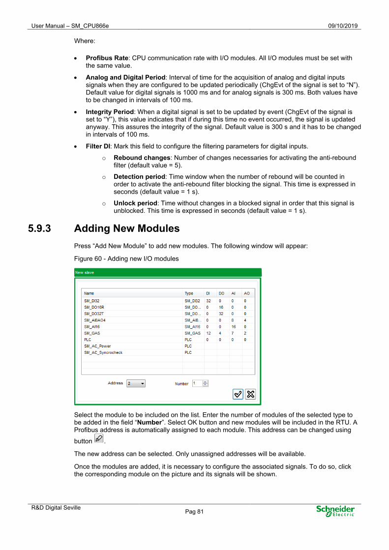
User Manual – SM_CPU866e 09/10/2019
R&D Digital Seville Pag 81
Where:
• Profibus Rate: CPU communication rate with I/O modules. All I/O modules must be set with the same value.
• Analog and Digital Period: Interval of time for the acquisition of analog and digital inputs signals when they are configured to be updated periodically (ChgEvt of the signal is set to “N”). Default value for digital signals is 1000 ms and for analog signals is 300 ms. Both values have to be changed in intervals of 100 ms.
• Integrity Period: When a digital signal is set to be updated by event (ChgEvt of the signal is set to “Y”), this value indicates that if during this time no event occurred, the signal is updated anyway. This assures the integrity of the signal. Default value is 300 s and it has to be changed in intervals of 100 ms.
• Filter DI: Mark this field to configure the filtering parameters for digital inputs.
o Rebound changes: Number of changes necessaries for activating the anti-rebound filter (default value = 5).
o Detection period: Time window when the number of rebound will be counted in order to activate the anti-rebound filter blocking the signal. This time is expressed in seconds (default value = 1 s).
o Unlock period: Time without changes in a blocked signal in order that this signal is unblocked. This time is expressed in seconds (default value = 1 s).
5.9.3 Adding New Modules Press “Add New Module” to add new modules. The following window will appear:
Figure 60 - Adding new I/O modules
Select the module to be included on the list. Enter the number of modules of the selected type to be added in the field “Number”. Select OK button and new modules will be included in the RTU. A Profibus address is automatically assigned to each module. This address can be changed using
button .
The new address can be selected. Only unassigned addresses will be available.
Once the modules are added, it is necessary to configure the associated signals. To do so, click the corresponding module on the picture and its signals will be shown.

09/10/2019 User Manual – SM_CPU866e
Pag 82 R&D Digital Seville
Figure 61 - Configuring acquisition signals for a I/O module
The configuration for each type of module which can be added is explained in further sections.
5.9.4 PLC Configuration By selecting a PLC module on the picture, the following configuration window will be displayed:
Figure 62 - PLC module configuration
There are three tabs; Configuration of the PLC, Inputs configuration and Outputs configuration.
The information entered in “Device ID”, “Param Data” and “Config Data” fields must be consistent with the information contained in the GSD file provided by the PLC’s manufacturer which is being configured.
• Name: Device or PLC's name
• PFB ID: PLC Identifier; a 4-digit hexadecimal number provided by the manufacturer. Enter the string labelled as Ident_Number in the “General Parameters” tab included in GSD file. For example, if “Ident_Number = 0x05FC”, the user should indicate “05FC” as PFB ID.
• Param Data: These are the data to be sent by the master Profibus when “Send Parameter Data” is enabled. In the GSD file, there is a section named “UserPrmData: Length and Preset:” which includes a string labelled as User_Prm_Data. This string will be entered in this field. For example, “User_Prm_Data=0x00,0x00,0x00”.

User Manual – SM_CPU866e 09/10/2019
R&D Digital Seville Pag 83
• Config Data: Sequence of bytes in hexadecimal that describes the map size for inputs and outputs for the Profibus slave. The documentation of the slave (device master file) must specify the map size of inputs and outputs. The format of these bytes is described in the standard EN 50170-8-2: 1996 page 832. A partial length is detailed simultaneously in each byte for inputs, outputs or inputs and outputs. The length of the complete map is the addition of the length indicated in all bytes. Below is an excerpt from the standard explaining the bytes format in hexadecimal:
Figure 63 - Example of a PLC Configuration
A GSD file is the configuration file supplied for the provider for the PLC
When the content of the messages to be exchanged with the PLC is completely defined, the user can configure the input and output signals which will store the information contained in these messages.
Use “Add” and “Remove” buttons to add and remove inputs from the list, respectively. After pressing “Add”, an input will be added with default settings, which can be modified, (except NUMBER) by clicking the selected item.
Select an input and press the “Remove” button to delete it from the list.
Press “Add” on the tab “Inputs” and a new Input will be created. The information associated for each signal is:
• Point number.
• Point’s name
• Type of point (size in bits within the message). The size can be 1, 2, 8, 16, 32 bits or 1 bit event.
• Address of the information related to the signal within the message.
5.9.5 Deleting a Module
To delete a module, select it on the picture and use button . The module will be removed from the tree after confirming the operation.
5.9.6 Generating Point in coreDb When all modules have been configured in the acquisition local panel, all acquisition and supervision signals associated to these modules have to be included in coreDB by pressing button
.
For example, for the module SM_AI16, the following signals are included into the analog table:

09/10/2019 User Manual – SM_CPU866e
Pag 84 R&D Digital Seville
Figure 64 - Analog signals included in coreDb
5.9.7 Signal Identification - Coordinates The coordinate is a unique identifier of a signal within a Bin. Its definition is different for each Device and the local acquisition is defined with ten digits with the following format:
2 BBB CC DDDD
• 2: The first number of its coordinate for all Saitel DP local acquisition signals will be 2.
• BBB: Three digits to indicate the point address according to the previous communication protocol. In the case of Profibus-DP, the address range is from 000 to 125.
• CC: Type of signal, which includes:
o 00: Diagnostic signals of the acquisition modules.
o 01: Analog input (16-bit).
o 02: Simple digital input (1 bit).
o 03: Counter (32 bits).
o 04: Analog output (16 bits).
o 05: Simple digital output (1 bit).
o 07: Double digital input (2 bits).
o 08: Frequency meter (32 bits).
o 09: Quick counter (32 bits).
o 10: Digital input (1 bit) (Inputs table of Profibus).
o 11: Digital input (2 bits) (Inputs table of Profibus).
o 12: Analog input (8 bits) (Inputs table of Profibus).
o 13: Analog input (16 bits) (Inputs table of Profibus).
o 14: Analog input (32 bits) (Inputs table of Profibus).
o 15: Double digital output (2 bits).
o 16: Digital output (1 bit) (Inputs table of Profibus).
o 17: Digital output (2 bits) (Inputs table of Profibus).
o 18: Analog output (8 bits) (Inputs table of Profibus).
o 19: Analog output (16 bits) (Inputs table of Profibus).
o 20: Analog output (32 bits) (Inputs table of Profibus).

User Manual – SM_CPU866e 09/10/2019
R&D Digital Seville Pag 85
• DDDD: Number of the signal within each type, that is, it does not need to match the physical position. The first signal of a type will be 0000, the second will be 0001 ..., with all the types of the previous point.
For example, if a coreDb point has associated the signal 2003020002 as source, then it means that this point of coreDb takes it’s the same value that the signal (0002) of the DI_ISIM (02) type, in the module with address 003, according to Profibus-DP (2) protocol.
NOTICE
More information about how to configure the local acquisition in the Easergy Builder user manual and the user manual for each Saitel DP module.

09/10/2019 User Manual – SM_CPU866e
Pag 86 R&D Digital Seville
6 Advanced Operations

User Manual – SM_CPU866e 09/10/2019
R&D Digital Seville Pag 87
Content 6 ADVANCED OPERATIONS .................................................................................... 86
6.1 LOADING/UPDATING BASELINE .............................................................................. 88 6.1.1 UPDATING USING SFTP .................................................................................. 88 6.1.2 UPDATING USING USB PORT ........................................................................... 89 6.1.3 UPDATING USING WEBAPP .............................................................................. 90
6.2 UPGRADING FIRMWARE - I/O AND COMMUNICATION MODULES ................................ 92 6.3 OPERATIVE SYSTEM UPDATE (LINUX) ..................................................................... 93 6.4 USING THE CONSOLE ............................................................................................. 95
6.4.1 BLMON COMMANDS ....................................................................................... 96 6.4.2 SAITEL COMMANDS ........................................................................................ 98

09/10/2019 User Manual – SM_CPU866e
Pag 88 R&D Digital Seville
6.1 Loading/Updating BaseLine You have several options to update the Baseline and/or OS in a SM_CPU866e module: using a SFTP client (for example, Filezilla), using webApp (SM_CPU866e web-based tool), or using a USB pen drive connected to the USB Host port.
You need the following:
• An Ethernet cable connected to the SM_CPU866e (ETH2 for example) and a PC's Ethernet port (both in the same network). This wired connection is only necessary when transferring the update file through SFTP or webApp. If using a pen drive, it would not be necessary.
• A file with the new Baseline to be installed. It will be a compressed file with a name like “Baseline_11.06.02.tar.gz”.
The file's name containing the image must have a specific syntax:
• It must start with "Baseline_", (no case sensitivity).
• It must finish with the ".tar.gz" extension
The following names are valid, for example: BaseLine_11.04.00.tar.gz, Baseline_10.tar.gz, and BASELINE_9.3.0.tar.gz.
6.1.1 Updating using SFTP An SFTP client must be available in the PC. Connect the SN_CPU866e and the PC in the same network. You can check if this connection is working fine by executing a ping command in a Microsoft command window:
Once the connection is verified, you open the FTP client software and establish connection with the CPU using the SFTP protocol and Installer (user) and Installer1! (password).
When connection is established, you can see the /home folder. You need to change to “/mnt/flash” or “/mnt/bf” folder and transfer the Baseline file from our PC.

User Manual – SM_CPU866e 09/10/2019
R&D Digital Seville Pag 89
Figure 65 - SFTP connection.
When loading is completed, press the Reset button on the CPU. If the console is available you can see that when browsing to the Baseline file, the installation is executed directly.
Once installed, the compressed file including the Baseline image is deleted.
Finally, reboot the system and Baseline is updated.
6.1.2 Updating using USB port You can use an USB device to upgrade the system. You only need to copy the file to the USB pen drive's root folder, connect the drive to the port and reboot the HUe.
During Linux initialization, the USB drive is installed in /mnt/usb1 and, if a file with a Baseline image is detected, the implementation is executed automatically.
There is a slight difference after the installation with respect to the previous section:
• The target image is not deleted from the /mnt/usb1 device. Therefore, you could use the pen drive to restore the same image in different CPU’s.
• Since the /mnt/usb1 image is not deleted, the system does not reboot. Thus, any "auto-installation" of the same image is prevented. We recommend that, after the file's automatic installation from the /mnt/usb1 device, you remove the pen drive and reboot the system manually.
The priority order for the update procedure is:
• File in USB drive
• File in /mnt/bf
• File in /mnt/flash

09/10/2019 User Manual – SM_CPU866e
Pag 90 R&D Digital Seville
NOTICE The filesystem used in SD card or pen drive must be FAT32.
6.1.3 Updating using webApp If you use a web browser, such as Chrome, you can connect to the web server using for example ETH2 port and indicating its IP address.
NOTICE Considering that the connection must be secure, you will type https://10.1.1.1 in the address bar (or the IP address associated to the ETHx port).
Figure 66 - webApp.
Log in with the “Installer” or “Engineer” user and the webApp main screen appears.
NOTICE Only users Engineer and Installer can update the new firmware to the SM_CPU866e
The current versions of the firmware installed in the SM_CPU866e module is displayed in the webApp main page:
Figure 67 - Information about Baseline version in the CPU

User Manual – SM_CPU866e 09/10/2019
R&D Digital Seville Pag 91
You can access to Maintenance Software for more detailed about the software versions in the CPU:
Figure 68 - Information about Device versions in the CPU
Use “Install new firmware” button to upgrade the firmware in the CPU. A wizard will help you during the upgrading process.
Figure 69 - Firmware upgrade
• You can drag and drop the file in the designated area or you can search for it using the “Select file” button (Step 1).
• Click the “Load” button (Step 2).
• Next, you need to confirm that the software file is correct (Step 3).
• Click the “Install new firmware”, and the software file will be sent to the CPU to install the new firmware (Step 4).
• Then, reboot the CPU (Step 5).
• Finally, the user will need to log in again and the CPU will be ready with the new software version.

09/10/2019 User Manual – SM_CPU866e
Pag 92 R&D Digital Seville
6.2 Upgrading Firmware - I/O and Communication Modules You can upgrade the I/O and communication modules using a console command.
NOTICE Only the following P/N of Saitel DP modules can be upgrade using a console command:
• SM_AI16 and SM_AI8AO4: C0 and later • SM_DO32T: Any version of the P/N M580x0000y. • SM_SER: Any version of the P/N M58100000y. • SM_DI32: Any version of the P/N M583x0000y. • SM_DO16R: Any version of P/N M586x0000y.
Other modules and previous versions of these modules only can be updated by authorized personal. For SM_CPU866e, only revision 01.00.13 and later of BLMon allow this functionality.
Once the RTU is configured, the CPU already knows the type of I/O and or communication modules installed on the backplane and their respective IP address.
According to the table below, copy the files associated to each type of module into the “flash” directory of RTU and execute the indicated command:
Table 14 – Files required for software update and commands
Module Binary files Console Command
SM_AI16 ST_AI16_C0.bin dpUpgrade <nº of slave> <software file>
SM_AI8AO4 ST_AI8AO4_C0.bin
SM_DO32T ST_DO32T_C0.bin
SM_DI32 ST_DO32T_C0.bin
SM_DO16R ST_DO32T_C0.bin
SM_SER ST_SER_C0.bin MUX_upgrade <Module nº>
• <nº of slave> could be a specific number or 0. If 0 is indicated, all installed modules of this type (depending on the software file) will be updated.
• <Module nº>: Between 1 and 8. SM_SER module’s address to be updated.
• <Software file>: File to be used for the upgrade. If the path is omitted in <software file> the file must be stored in the folder /mnt/flash/cfgFiles.
NOTICE It is recommended to use the user Installer to login into the console tool.
For example, executing the command dpUpgrade 0 ST_DO32T_C0.bin, all SM_DO32T modules on the backplane will be upgraded using the file ST_DO32T_C0.bin in “/mnt/flash/cfgFiles”.

User Manual – SM_CPU866e 09/10/2019
R&D Digital Seville Pag 93
After executing the command, the console will display messages to report the process progress. Finally, if the process is correct, the acquisition blocks will be updated to the adequate firmware.
There are two useful console commands:
• dpSniffUpgradeOn and dpSniffUpgradeOff: Show or not in the console window all messages interchanges between the CPU and the I/O modules to be updated.
• dpVersion < nº of slave>: Show the version of the specified module.
NOTICE It’s necessary to have correctly configured the backplane in the CPU before to execute these commands. The CPU has to know previously the types of slaves and its addresses. Please, see following chapters in this manual.
6.3 Operative System Update (Linux)
DANGER All operation indicated in this paragraph only can be done by advanced users. An error doing any of the following command could
When you update the baseline, the Linux is updated to the correct version too.
The following procedure, only must be executed when you need to remove all information in the CPU, OS, software and configuration files.
The following files as required:
• File uImage-sm_cpu_dct.bin (OS kernel).
• File uImage-sm_cpu_dct.dtb (hardware profile)
• File u-boot.bin (Boot console for Linux)
• TFTP server (for example CISCO TFTP server v1.1 is used in this manual)
All following steps must be executed from the u-Boot console. In order to access this tool, reboot the CPU and press any key when the message “Hit any key to stop autoboot: “ as is shown:
Figure 70 - u-Boot console.
Now, the u-Boot console is available with the prompt “=>”.

09/10/2019 User Manual – SM_CPU866e
Pag 94 R&D Digital Seville
It’s recommendable to remove the content of /flash and /bf folder in order to "clean" the CPU. Please, execute following commands in the u-Boot prompt:
• => erase f0000000 +4000000
• => erase ec000000 +2000000
DANGER Take special care with these commands, an error in the indicated addresses could cause the equipment to become inoperative and need to be sent to the factory for repair.
This operation could take some time depending on the amount of data to be removed.
First, from the u-Boot console, set up the environment variables netmask, ipaddr and serverip.
See the next example:
• => setenv netmask 255.255.0.0
• => setenv ipaddr 172.19.131.10 (Temporary IP for ETH2)
• => setenv serverip 172.19.131.2 (PC where the TFTP is running) If you want to save these values run the “saveenv” command.
Figure 71 - Setting the environment variables
Start the TFTP server on your PC (this is supposed to have the IP address specified on the serverip environment variable). Copy the file “uImage-sm_cpu_dct.bin” file into the TFTP folder. For example, using CISCO server, select View Options and this directory is set on the field “TFTP server root directory”.
From the u-Boot console run the command “=> run update_kernel”.
Figure 72 - Message on the console while the file Is uploaded from TFTP server

User Manual – SM_CPU866e 09/10/2019
R&D Digital Seville Pag 95
Figure 73 - TFTP Server
At the end, the Linux BSP should have been flashed successfully on the SM_CPU866e board.
In addition, the hardware has to be updated using the file “uImage-sm_cpu_dct.dtb”.
Copy this file on the TFTP server root directory and execute the command “=> run update_dtb” in the uBoot console.
Now, the hardware is updated and finally, the uBoot has to be updated too.
Copy the file “u-boot.bin” on the TFTP server root directory and execute the command “=> run update_uboot”.
When the process is finished, reboot the CPU using the command “=>boot”.
Now, Linux OS is updated.
NOTICE In this moment, only the user “admin” with password “12345678” is available and the IP for ETH2 is 10.1.1.1 with netmask 255.0.0.0.
6.4 Using the Console The SM_CPU866e operating system offers a high-priority command console to help with certain monitoring and diagnostic tasks.
The connection to this console from the PC is established through the CON port. Section 4.1.1 in this manual describes how you can access the command console.
You need to take the following factors into account:
• The use of the command console must be restricted only to expert operators in the system.
• The command execution in the console must return a “0” character when outputted. If it returns other values, then there has been a problem in the execution. It is usually caused by parameters with the wrong format.
• When executing a command for any controller, it must be saved into the memory to solve this problem, that is, the controller must be included in the configuration loaded in the CPU from Easergy Builder.

09/10/2019 User Manual – SM_CPU866e
Pag 96 R&D Digital Seville
NOTICE
Only the Device controllers included in the current configuration will be loaded into the memory.
Then, the commands available in the console for the Installer user are displayed below. To find out the arguments that a command requires, you have used the following convention:
• (No parameters): The command must be executed directly, with no additional parameter.
• <XX>: Required parameter. It must be replaced with the XX value. The symbols <>MUST NOT be included.
• [YY]: Optional argument. If using the argument, it must be replaced with the YY value. The characters [] MUST NOT be included.
6.4.1 BLMon Commands When accessing the console with the Installer user (recommended), the BLMon menu is directly shown. The commands in this menu are executed on the operating system's prompt. Most commands shown below are NOT available for the rest of the users.
The BLMon menu includes the following commands:
Table 15 – BLMon commands
Command Description
m Print the BLMon menu. Selecting “m”, the BLMon main menu is shown
s Show coreDb state. Show the general state of the coreDb. This command is similar to “coreDbState”.

User Manual – SM_CPU866e 09/10/2019
R&D Digital Seville Pag 97
Command Description
t Show thm information. Show the sinchronization state. This command is similar to “thmShow”.
e Start events monitoring.
If command “e” is executed, the monitorization event is started. This command is similar to “coreDbShowEvents”.
u Stop events monitoring. If command “u” is executed, the monitorization event is stoped. This command is similar to “coreDbUnShowEvents”.
c Start channel monitoring.
Start the monitorization for a communication channel. This command shows all configured channels and asks user to select one of them. You coud press “enter” in order to cancel this command. This command is similar to “chanSniffOn”.
o Stop channel monitoring. If command “o” is executed, the monitorization of all channels is stoped. This command is similar to “chanSniffOff”.
l Start link monitoring.
Start the monitorization for a communication link. This command shows all configured links and asks user to select one of them. You coud press “enter” in order to cancel this command. This command is similar to “chlnSniffOn”.
p Show processes. Information about all process that are running in the CPU. This command shows the output of the system command “ps –eTcl”.

09/10/2019 User Manual – SM_CPU866e
Pag 98 R&D Digital Seville
Command Description
v Show OS version. Pressing “v” the Linux version is shown. It is similar to the system command “version”.
h Help.
Pressing “h” you can see a detailed help about any available command in the system. In addition to commands included in the menu, the user has additional commands that can be executed using the prompt BLMon. Press "h", write the desired command in FUNCTION_HELP and a detailed help will be shown with the correct sintax. If you write "a" when FUNCTION_HELP is required, a list with all available commands is shown.
f Stop link monitoring. If command “f” is executed, the monitorization of all links is stoped. This command is similar to “chlnSniffOff”.
b Show baseline version. Pressing “b” the Baseline version is shown. It is similar to the command “baselineShowVer”.
6.4.2 Saitel Commands This paragraph shows the more used commands available for SM_CPU866e:
Table 16 – Saitel commands
Command Parameters / Description
baselineShowVer (Without parameters) Show versions of all loaded modules. For example:
chanShowVer (Without parameters)
Show information about the channels management module.
chanSniffOn “<Channel name>” Enable the transparent mode for the specific channel. The channel’s name matches with the name defined in the channel module. It is can be disabled with chanSniffOff.
chanSniffOff “<Link name>” Disable the transparent mode for the specific channel. It was enabled with chanSniffOn.

User Manual – SM_CPU866e 09/10/2019
R&D Digital Seville Pag 99
Command Parameters / Description
chlnSniffOn “<Link name>” Enable the transparent mode for the specific link. It is can be disabled with chlnSniffOff.
chlnSniffOff Disable the transparent mode for the specific link. It was enabled with chlnSniffOn.
dnpeShowVer (Without parameters) Show information about the slave dnp module.
dnpmShowVer (Without parameters) Show information about the master dnp module.
laqShowVer (Without parameters) Show information about the version of the local acquisition Device Controller.
laqPfbMShowVer (Without parameters) Show information about the version of the Profibus module.
laqShowEvents (Without parameters) Start local acquisition events monitoring.
laqShowMod (Without parameters) Start local acquisition events monitoring.
laqUnShowEvents (Without parameters)
Stop local acquisition events monitoring.
logbaselineShowVer (Without parameters) Write in sysLog the versions of all loaded modules.
pfbSniffOff (Without parameters) Stop Profibus monitoring.
pfbSniffOn (Without parameters) Start Profibus monitoring.
supCpuUsage (Without parameters) Show CPU usage.
supShowVer (Without parameters) Show information about the supervision module.
sup_wdShowTaskList (Without parameters) Show tasks that have been subscribed to watchdog.

09/10/2019 User Manual – SM_CPU866e
Pag 100 R&D Digital Seville
Command Parameters / Description
thmConsoleSetTime “<YY>:<MM>:<DD>:<HH>:<MM>:<SS>” Allow changing the synchronization time of the RTU using the console. For example:
thmShow (Without parameters)
Show information about the synchronization status of the RTU.
thmShowVer (without parameters) Show information about the synchronization module.
x_blockPoint “<Point type>”, “<Point name>”, <Flag> If <Flag> is 1, block the point <Point name>. If <Flag> is 0, unlock the point <Point name> NOTE: The <Flag> must be writing without quotation marks.
x_krunchData “<Point type>”, “<Point name>”, “<Value>” Write a point. For example: x_krunchData “setPoint”, “M006_AO_000”, “20”. You can view the new value of this point with Saitel Webtool or using the command x_readData. NOTE: All parameters must be writing within quotation marks.
x_overridePoint “<Point type>”, “<Point name>”, <Flag> If <Flag> is 1, set override value for the <Point name>. If <Flag> is 0, clear override value for the <Point name> NOTE: The <Flag> must be writing without quotation marks.
x_readData “<Point type>”, “<Point name>” Read information from coreDb and print it on the console window. For example:

User Manual – SM_CPU866e 09/10/2019
R&D Digital Seville Pag 101
7 Technical Specifications Table

09/10/2019 User Manual – SM_CPU866e
Pag 102 R&D Digital Seville
Hardware Specifications Processing unit Freescale QorlQ Dual™ P1021E
Power Architecture® e500v2
Data bus: 32-bits
Clock frequency: 800 MHz
RTC accuracy High accuracy, < 5 ppm / ºC derivation
FLASH memory (NOR) 128 MB
FLASH memory (NAND) 128 MB
Static RAM memory 4 MB
Assurance for static RAM Internal lithium battery
Battery CR2450N (3 V, Renata)
Dynamic RAM memory (DDR3) 512 MB
Autonomy in power down Up to 6 months for static RAM and RTC
Consumption 10 W Maximum
Weight 700 g
Dimensions 245 mm x 170 mm x 45 mm
Coating AVR80 (Depending on P/N)
Protection degree IP20
Range of temperature Operation: From -40º C to +80º C
Storage: From -40º C to +125º C
Interfaces Console port (CON) Isolated RS-232 communications
38.400-8-N-1
Serial ports
(COM1, COM2, COM3 & COM4)
Asynchronous RS-232 communications
Isolated (COM1 & COM2) / Non-isolated (COM3 & COM4)
RJ-45 connector
Category 5 cable or better must be used (Max: 100 m)
Max. 38,400 bps
GPS port (Only COM1)
USB port 2.0 (Host)
SD card SD, MMC and SDHC devices.
Up to 32 GB.
Communication between modules Profibus DP (through the backplane)
Max number of SM_SER modules 8 (all of them in the first backplane)
IRIG-B 2-pole terminal block with isolation
1.5 mm² (15 AWG)
External watchdog (WD) Maximum capacity of current: 100 mA
2-pole terminal block with isolation
1.5 mm² (15 AWG)
Ethernet ports (Copper)
(ETH1, ETH2, ETH3 and ETH4)
10/100/1000BaseT with auto-negotiation
Connector RJ-45
Category 5 cable or better must be used (Max: 100 m).
Ethernet ports (Fiber Optic)
(ETH3 and ETH4)
100BaseFX (MMF, distance < 2 km in full-duplex)
1000BaseSX (MMF 62.5 µm, distance < 220 m / MMF 50 µm, distance < 500 m)
1000BaseLX (SMF 50 µm, distance < 5 km)

User Manual – SM_CPU866e 09/10/2019
R&D Digital Seville Pag 103
Interfaces Recommended transceivers LC-Duplex connector for SFP module (not provided)
HFBR 57E0PZ / HFBR 57E5APZ
AFBR-5705ALZ / FTLF8519P3BTL
AFCT-5715ALZ / FTLF1323P1BTR
FTLF8519P3BTL-HM / FTLF1323P1BTR-HM / FTLF1317P2BTL-HM
GP-8524-S5CD / GP-1303-02CD / GP-3103-L2CD / GP-3124-L2CD
Software Operating System Linux
Discrimination time for events 1 ms
Watchdog software Internal
External synchronization
GPS
IRIG-B
Protocol
Console
PTP
IRIG-B TTL input signal
Protocols: IRIG-B002, IRIG-B003, IRIG-B006 and IRIG-B007
Security control
Cybersecurity brick included
Embedded firewall
Secured interfaces
User management based on a RBAC model
Cybersecurity Based on IEC62351
IEC62443
Security Engine SEC 3.3.2 (XOR acceleration)
Supported cryptographic algorithms 3DES, AES, MD5/SHA, RSA/ECC, & FIPS (determinist generator)
Processing Single pass encryption and authentication
Security protocols TLS, SSH, DNP Secure Authentication (SaV2 & SaV5), IEC-60870-5-104/101 Secure Authentication.
Ordering Options

09/10/2019 User Manual – SM_CPU866e
Pag 104 R&D Digital Seville
CE Mark Standards, Directives and harmonized norms.
LVD – Low Voltage Directive Directive 2014/35/UE
EMC – Electromagnetic Compatibility Directive 2014/30/UE
RoHS 2 Directive 2011/65/EU, according to royal legislative decree (RD) 219/2013
WEEE – Waste Electrical and Electronic Equipment
Directive 2012/19/UE according to RD 110/2015
EMC tests according to EN 60870-2-1:1996
IEC/TS 61000-6-5:2015
Emission EMC tests Radiated emissions
EN 55022:2010 + AC:2011
From 30 to 1000 MHz (Class A)
Conducted emissions
EN 55022: 2010 + AC:2011 From 0.15 to 30 MHz (Class A)
Immunity EMC tests Electrostatic discharges (ESD)
EN 61000-4-2:2010 Air ±8 kV / Direct and indirect contact ±6 kV
Radiated, radio-frequency, electromagnetic field
EN 61000-4-3:2006 From 80 to 2700 MHz (Level: 10 V/m).
Electrical fast transient/burst
EN61000-4-4:2004 / A1 + Corr (2010)
Power and communications: ±4 kV, 5kHz.
Surge
EN 61000-4-5:2006 + Corr (2010)
±4 kV symmetric and asymmetric
Conducted disturbances, radio-frequency fields
EN 61000-4-6:2007 0.15 – 80 MHz 80% AM (Level: 10 and 3 VRMS).
Magnetic field
EN 61000-4-8:2010. 100 A/m, 1000 A/m (59 Hz).
Immunity to conducted disturbances, induced by radio-frequency fields
EN 61000-4-16:1998 Power: 30 V (50 Hz), 300 V (50 Hz)
Damped oscillatory wave
EN 61000-4-18:2007 + A1:2010
Power: ±1 kV (symmetrical), ±2.5 kV (asymmetrical)
Electric Safety Insulation coordination for measuring relays and protection equipment. Requirements and tests
IEC 60255-5:2000 / EN 60255-5:2001 / UNE EN 60255-5:2002 (Paragraph 6)
RoHS Directive 2011/65/UE Verification of Lead, Cadmium, Mercury, Chrome and Bromine
Environmental tests Cold - EN 60068-2-1:2007 -40 ºC during 16 h (100 h)
Dry heat - EN 60068-2-2:2007 +85 ºC during 16 h (100 h)
Damp heat - EN 60068-2-30:2005 +25 ºC a +55 ºC with 95% RH (2 cycles of 24h each)

User Manual – SM_CPU866e 09/10/2019
R&D Digital Seville Pag 105
Index of Figures
Figure 1 - Barrier of protection for elements with dangerous voltages. ..................................................................... 10
Figure 2 - Yellow and Green cable for earthing. ......................................................................................................... 11
Figure 3 - Technical label. .......................................................................................................................................... 14
Figure 4 - Saitel DP architecture ................................................................................................................................. 18
Figure 5 - Profibus TTL and Profibus RS-485 ............................................................................................................ 19
Figure 6 - Buses in a backplane ................................................................................................................................. 20
Figure 7 - BaseLine Software Platform ....................................................................................................................... 21
Figure 8 - Relation between coreDb and other applications ...................................................................................... 21
Figure 9 - coreDb operation example ......................................................................................................................... 25
Figure 10 - LED indicators .......................................................................................................................................... 26
Figure 11 - Backplane`s positions .............................................................................................................................. 30
Figure 12 - Saitel DP module inserted incorrectly ...................................................................................................... 31
Figure 13 - SM_CPU866e. Front view. ....................................................................................................................... 32
Figure 14 - SM_CPU866e – Faceplate ...................................................................................................................... 32
Figure 15 - Two CPU modules in the same backplane .............................................................................................. 34
Figure 16 - Two CPUs in different backplanes ........................................................................................................... 34
Figure 17 - Switching using the MSAC module .......................................................................................................... 35
Figure 18 - Switching status under Cold Data mode .................................................................................................. 36
Figure 19 - Switching status under Hot Data mode .................................................................................................... 37
Figure 20 - Dual system .............................................................................................................................................. 38
Figure 21 - Reset button ............................................................................................................................................. 38
Figure 22 - Serial communications ............................................................................................................................. 39
Figure 23 - Cable description for redundancy ............................................................................................................ 40
Figure 24 - PC connection (DB-9 connector). ............................................................................................................ 41
Figure 25 - Ethernet Ports. ......................................................................................................................................... 41
Figure 26 - SFP modules to install in the ports ETH3-FX and ETH4-FX of SM_CPU866e ....................................... 43
Figure 27 - IRIG-B and Watchdog ports. .................................................................................................................... 43
Figure 28 - IRIG-B input pinout. .................................................................................................................................. 43
Figure 29 - Profibus switches for module configuration ............................................................................................. 44
Figure 30 - Profibus switches for module configuration ............................................................................................. 49
Figure 31 - BLMon menu ............................................................................................................................................ 49
Figure 32 - Network interfaces setting ........................................................................................................................ 51
Figure 33 - Using routers to configure subnets .......................................................................................................... 52

09/10/2019 User Manual – SM_CPU866e
Pag 106 R&D Digital Seville
Figure 34 - Firewall configuration ............................................................................................................................... 53
Figure 35 - Environment variables .............................................................................................................................. 54
Figure 36 - Managing users in HUe. ........................................................................................................................... 56
Figure 37 - Cybersecurity Log. ................................................................................................................................... 58
Figure 38 - Configuring backplane.............................................................................................................................. 59
Figure 39 - Acquisition strategy window ..................................................................................................................... 60
Figure 40 - New RTU .................................................................................................................................................. 65
Figure 41 - New configuration ..................................................................................................................................... 67
Figure 42 - New configuration in the RTU tree ........................................................................................................... 67
Figure 43 - Configuration mode .................................................................................................................................. 68
Figure 44 - Contextual menu for Configuration .......................................................................................................... 68
Figure 45 - Description of the device .......................................................................................................................... 68
Figure 46 - Module management window .................................................................................................................. 69
Figure 47 - Channel configuration window. ................................................................................................................ 69
Figure 48 - Link configuration window. ....................................................................................................................... 70
Figure 49 - SOE configuration .................................................................................................................................... 72
Figure 50 - Using formulas in coreDb ......................................................................................................................... 72
Figure 51 - Supervision points for SM_CPU866e ....................................................................................................... 73
Figure 52 - Redundancy configuration ....................................................................................................................... 76
Figure 53 - Using several IPs to a port. ...................................................................................................................... 77
Figure 54 - Configuring local acquisition for Saitel DP ............................................................................................... 78
Figure 55 - coreDb Menu ............................................................................................................................................ 78
Figure 56 - Status signals defined in coreDb .............................................................................................................. 79
Figure 57 - Available Saitel DP modules in Easergy Builder ...................................................................................... 79
Figure 58 - Configuring local acquisition .................................................................................................................... 80
Figure 59 - Configuring the acquisition strategy ......................................................................................................... 80
Figure 60 - Adding new I/O modules .......................................................................................................................... 81
Figure 61 - Configuring acquisition signals for a I/O module ...................................................................................... 82
Figure 62 - PLC module configuration ........................................................................................................................ 82
Figure 63 - Example of a PLC Configuration .............................................................................................................. 83
Figure 64 - Analog signals included in coreDb ........................................................................................................... 84
Figure 65 - SFTP connection. ..................................................................................................................................... 89
Figure 66 - webApp. ................................................................................................................................................... 90
Figure 67 - Information about Baseline version in the CPU ....................................................................................... 90
Figure 68 - Information about Device versions in the CPU ........................................................................................ 91

User Manual – SM_CPU866e 09/10/2019
R&D Digital Seville Pag 107
Figure 69 - Firmware upgrade ................................................................................................................................... 91
Figure 70 - u-Boot console. ........................................................................................................................................ 93
Figure 71 - Setting the environment variables ............................................................................................................ 94
Figure 72 - Message on the console while the file Is uploaded from TFTP server .................................................... 94
Figure 73 - TFTP Server ............................................................................................................................................. 95

09/10/2019 User Manual – SM_CPU866e
Pag 108 R&D Digital Seville
Index of Tables
Table 1 – Symbols ........................................................................................................................................................ 9
Table 2 – Led indicators meaning ............................................................................................................................... 26
Table 3 – Pinout of COM1, COM3 and COM4 ports. ................................................................................................. 39
Table 4 – Pinout of COM2 port ................................................................................................................................... 40
Table 5 – CPU - Pinout of the port CON. ................................................................................................................... 41
Table 6 – SM_CPU866e - Pinout of the copper ports ETHx. ..................................................................................... 42
Table 7 – SM_CPU866e – USB port .......................................................................................................................... 44
Table 8 – Default IP addresses .................................................................................................................................. 48
Table 9 – Default users ............................................................................................................................................... 48
Table 10 – Rights ........................................................................................................................................................ 56
Table 11 – User’s privileges. ...................................................................................................................................... 57
Table 12 – SM_CPU866e - Channels to be defined .................................................................................................. 70
Table 13 – Saitel DP supervision points ..................................................................................................................... 74
Table 14 – Files required for software update and commands .................................................................................. 92
Table 15 – BLMon commands .................................................................................................................................... 96
Table 16 – Saitel commands ...................................................................................................................................... 98

User Manual – SM_CPU866e 09/10/2019
R&D Digital Seville Pag 109
Glossary A A: Ampere.
AC: Alternate Current.
AI: Analog Input.
AO: Analog Output.
AWG: American Wire Gauge.
B Bps: Bits per second.
C ºC: Celsius degree.
COM: Communication Port.
CPU: Central Processing Unit.
CTS: Clear to Send.
D DC: Direct Current.
DI: Digital Input.
DO: Digital Output.
DRAM: Dynamic Random-Access Memory.
E EMC: Electromagnetic Compatibility.
EPROM: Erasable Programmable Read Only Memory
F FTP: File Transfer Protocol.
G g: Gram.

09/10/2019 User Manual – SM_CPU866e
Pag 110 R&D Digital Seville
GPS: Global Positioning System.
H Hz: Hertz.
I IED: Intelligent Electronic Device.
I/O: Input / Output.
IRIG: Inter Range Instrumentation Group.
IRIG-B: Mode B of the standard IRIG.
ISO 9001: International standard for Quality Systems.
K KB: Kilobyte.
kHz: Kilohertz.
L LAN: Local Area Network.
LED: Light Emitting Diode.
M mA: Milliampere.
MHz: Megahertz.
MB: Megabyte.
Mbps: Megabits per second.
m: Meter.
mm: Millimeter.
ms: Millisecond.
N N/A: Non-Application.
P

User Manual – SM_CPU866e 09/10/2019
R&D Digital Seville Pag 111
PC: Personal Computer.
PPS: Pulses per Second.
PS: Power Supply.
PWR: Power.
R RAM: Random Access Memory.
RS-232: Communication standard.
RS-485: Multipoint differential Bus.
RTDB: Real Time DataBase.
RTS: Request To Send.
RTU: Remote Terminal Unit.
Rx: Reception
S s: Second.
SCADA: Supervisory Control And Data Acquisition.
SM_AI16: Analog Inputs module.
SM_AI8AO4: Analog Inputs and Outputs module.
SM_DI32: Digital Inputs module.
SM_DO16R: Digital Outputs to Relay module.
SM_DO32T: Digital Outputs to Transistor.
SM_PS: Power supply module.
SM_PS40: Power supply module.
SM_SER: Communication module for expansion.
SNTP: Simple Network Time Protocol.
SRAM: Static Random-Access Memory.
T TCP/IP: Transmission Control Protocol/Internet Protocol.

09/10/2019 User Manual – SM_CPU866e
Pag 112 R&D Digital Seville
TFTP: Trivial File Transfer Protocol.
Tx: Transmission.
V VAC: Volt of Alternate Current.
VDC: Volt of Direct Current.
W W: Watt.
.

User Manual – SM_CPU866e 09/10/2019
R&D Digital Seville Pag 113
Printed in:
Tuesday, October 15, 2019
Schneider Electric
C/ Charles Darwin s/n Parque Científico y Tecnológico de la Cartuja Seville, Spain
©2019 All rights reserved. The information contained in this document is confidential and is owned by Schneider Electric. It cannot be copied or distributed in any way, unless there is express written authorization by Schneider Electric. Although this information was verified at the time of publication, may be subject to change without notice.
SE-M578-USR-01 10/2019